

Page 1

Local Control Panel Kit Install Guide:
Intel® Entry Server Chassis SC5275-E
UP/DP/WS/BRP
Intel® Entry Server Chassis SC5299-E
DP/WS/BRP
Intel® Server Chassis SC5300
Intel® Server Chassis SC5400
A Guide for Technically Qualified Assemblers of Intel® Identified Subassemblies/Products
Intel Order Number: C77420-002
Page 2

Disclaimer
Information in this document is provided in connection with Intel® products. No license, express or implied, by
estoppel or otherwise, to any intellectual property rights is granted by this document. Except as provided in Intel's
Terms and Conditions of Sale for such products, Intel assumes no liability whatsoever, and Intel disclaims any
express or implied warranty, relating to sale and/or use of Intel® products including liability or warranties relating to
fitness for a particular purpose, merchantability, or infringement of any patent, copyright or other intellectual property
right. Intel products are not designed, intended or authorized for use in any medical, life saving, or life sustaining
applications or for any other application in which the failure of the Intel product could create a situation where
personal injury or death may occur. Intel may make changes to specifications and product descriptions at any time,
without notice.
Intel® server boards contain a number of high-density VLSI and power delivery components that need adequate
airflow for cooling. Intel's own chassis are designed and tested to meet the intended thermal requirements of these
components when the fully integrated system is used together. It is the responsibility of the system integrator that
chooses not to use Intel developed server building blocks to consult vendor datasheets and operating parameters to
determine the amount of airflow required for their specific application and environmental conditions. Intel
Corporation can not be held responsible if components fail or the server board does not operate correctly when used
outside any of their published operating or non-operating limits.
Intel, Intel Pentium, and Intel Xeon are trademarks or registered trademarks of Intel Corporation or its subsidiaries in
the United States and other countries.
* Other names and brands may be claimed as the property of others.
Copyright © 2005-2006, Intel Corporation. All Rights Reserved
ii Local Control Panel Kit Install Guide
Page 3

Safety Information
r
Important Safety Instructions
Read all caution and safety statements in this document before performing any of the
instructions. See also Intel Server Boards and Server Chassis Safety Information on the
®
Server Deployment Toolkit CD and/or at http://support.intel.com/support/
Intel
motherboards/server/sb/cs-010770.htm.
Wichtige Sicherheitshinweise
Lesen Sie zunächst sämtliche Warnund Sicherheitshinweise in diesem Dokument, bevor
Sie eine der Anweisungen ausführen. Beachten Sie hierzu auch die Sicherheitshinweise zu
Intel-Serverplatinen und Servergehäusen auf der Intel
oder unter http://support.intel.com/support/motherboards/server/sb/cs-010770.htm.
Consignes de sécurité
®
Server Deployment Toolkit CD
Lisez attention toutes les consignes de sécurité et les mises en garde indiquées dans ce
document avant de suivre toute instruction. Consultez Intel Server Boards and Server
Chassis Safety Information sur le Intel
vous sur le site http://support.intel.com/support/motherboards/server/sb/cs-010770.htm.
®
Server Deployment Toolkit CD ou bien rendez-
Instrucciones de seguridad importantes
Lea todas las declaraciones de seguridad y precaución de este documento antes de realizar
重要安全指导
cualquiera de las instrucciones. Vea Intel Server Boards and Server Chassis Safety
Information en el Intel
support/motherboards/server/sb/cs-010770.htm.
在执行任何指令之前,请阅读本文档中的所有注意事项及安全声明。 和/或
http://support.intel.com/support/motherboards/server/safecert.htm
Boards and Server Chassis Safety Information(《Intel
服务器主板与服务器机箱安全信息》)。
®
Server Deployment Toolkit CD y/o en http://support.intel.com/
上的 Intel Serve
Local Control Panel Kit Install Guide iii
Page 4

Safety Information
Warnings
Heed safety instructions: Before working with your server product, whether you are
using this guide or any other resource as a reference, pay close attention to the safety
instructions. You must adhere to the assembly instructions in this guide to ensure and
maintain compliance with existing product certifications and approvals. Use only the
described, regulated components specified in this guide. Use of other products /
components will void the UL listing and other regulatory approvals of the product and
will most likely result in noncompliance with product regulations in the region(s) in which
the product is sold.
System power on/off: The power button DOES NOT turn off the system AC power. To
remove power from system, you must unplug the AC power cord from the wall outlet.
Make sure the AC power cord is unplugged before you open the chassis, add, or remove
any components.
Hazardous conditions, devices and cables: Hazardous electrical conditions may be
present on power, telephone, and communication cables. Turn off the server and
disconnect the power cord, telecommunications systems, networks, and modems attached
to the server before opening it. Otherwise, personal injury or equipment damage can
result.
Electrostatic discharge (ESD) and ESD protection: ESD can damage disk drives,
boards, and other parts. We recommend that you perform all procedures in this chapter
only at an ESD workstation. If one is not available, provide some ESD protection by
wearing an antistatic wrist strap attached to chassis ground any unpainted metal surface on
your server when handling parts.
ESD and handling boards: Always handle boards carefully. They can be extremely
sensitive to ESD. Hold boards only by their edges. After removing a board from its
protective wrapper or from the server, place the board component side up on a grounded,
static free surface. Use a conductive foam pad if available but not the board wrapper. Do
not slide board over any surface.
Installing or removing jumpers: A jumper is a small plastic encased conductor that slips
over two jumper pins. Some jumpers have a small tab on top that you can grip with your
fingertips or with a pair of fine needle nosed pliers. If your jumpers do not have such a
tab, take care when using needle nosed pliers to remove or install a jumper; grip the
narrow sides of the jumper with the pliers, never the wide sides. Gripping the wide sides
can damage the contacts inside the jumper, causing intermittent problems with the
function controlled by that jumper. Take care to grip with, but not squeeze, the pliers or
other tool you use to remove a jumper, or you may bend or break the pins on the board.
iv Local Control Panel Kit Install Guide
Page 5

Contents
Contents
Safety Information ..................................................................................................... iii
Important Safety Instructions ................................................................................................ iii
Wichtige Sicherheitshinweise ............................................................................................... iii
Consignes de sécurité .......................................................................................................... iii
Instrucciones de seguridad importantes ............................................................................... iii
Local Control Panel Kit Installation Instructions .................................................... 1
Before You Begin ...................................................................................................................1
Kit Content List ........................................................................................................................... 1
Tools and Supplies Needed ........................................................................................................ 2
System References .................................................................................................................... 2
Installation Instructions for Intel® Server Chassis SC5300/SC5400 .....................................2
Remove Access Cover ............................................................................................................... 2
Remove Bezel Assembly ............................................................................................................ 3
Remove Outer Bezel Door from Bezel Assembly ....................................................................... 4
Remove Upper Third of Bezel Grill ............................................................................................. 5
Install LCP Grill ........................................................................................................................... 5
Remove Lowest CD-ROM/DVD Drive Filler Panel ..................................................................... 6
Install EMI Shield onto LCP Carrier ............................................................................................7
Inserting LCP Carrier into Drive Bay of Server Chassis ............................................................. 7
Route LCP Cable ........................................................................................................................ 8
Connect LCP Cable to LCP Header of Server Board ................................................................. 9
Replace Bezel Assembly .......................................................................................................... 10
Replace Access Cover ............................................................................................................. 11
Installation Instructions for Intel® Entry Server Chassis SC5275-E .................................... 12
Remove Access Cover ............................................................................................................ 12
Remove Bezel .......................................................................................................................... 13
Remove Lowest CD-ROM/DVD Drive Filler Panel ................................................................... 13
Install EMI Shield onto LCP Carrier .......................................................................................... 14
Inserting LCP Carrier into Drive Bay of Server Chassis ........................................................... 14
Connect LCP Cable to LCP Header on Server Board .............................................................. 16
Replace Bezel ........................................................................................................................... 17
Replace Access Cover ............................................................................................................. 18
Installation Instructions for Intel® Entry Server Chassis SC5299-E .................................... 19
Remove Access Cover ............................................................................................................ 19
Remove Bezel .......................................................................................................................... 19
Remove Lowest CD-ROM/DVD Drive Filler Panel ................................................................... 20
Install EMI Shield onto LCP Carrier .......................................................................................... 21
Inserting LCP Carrier into Drive Bay of Server Chassis ........................................................... 22
Route LCP Cable ...................................................................................................................... 22
Connect LCP Cable to LCP Header on Server Board .............................................................. 23
Local Control Panel Kit Install Guide v
Page 6

Contents
Replace Bezel .......................................................................................................................... 24
Replace Access Cover ............................................................................................................. 25
vi Local Control Panel Kit Install Guide
Page 7

List of Figures
List of Figures
Figure 1. Removing Access Cover............................................................................................. 2
Figure 2. Removing Bezel Assembly ......................................................................................... 3
Figure 3. Removing Outer Bezel Door from Bezel Assembly ................................................... 4
Figure 4. Removing Upper One-third of Bezel Grill ................................................................... 5
Figure 5. Installing LCP Grill....................................................................................................... 5
Figure 6. Removing Lowest Floppy/CD-ROM/DVD Drives or Filler Panel................................. 6
Figure 7. Installing EMI Shield on LCP Carrier........................................................................... 7
Figure 8. Attaching Drive Rails to LCP Carrier........................................................................... 7
Figure 9. Installing LCP Carrier .................................................................................................. 8
Figure 10. Routing the LCP Cable ............................................................................................ 8
Figure 11. Attaching LCP Cable to Header on Intel® Server Board SE7520AF2 ..................... 9
Figure 12. Attaching LCP Cable to Header on Intel® Server Board SE7520BD2 ..................10
Figure 13. Installing Inner Bezel Door...................................................................................... 11
Figure 14. Replacing Access Cover ......................................................................................... 11
Figure 15. Removing Access Cover......................................................................................... 12
Figure 16. Removing Bezel...................................................................................................... 13
Figure 17. Removing Lowest Floppy/CD-ROM/DVD Drives or Filler Panel............................. 13
Figure 18. Installing EMI Shield on LCP Carrier....................................................................... 14
Figure 19. Installing Drive Rails to LCP Carrier........................................................................ 14
Figure 20. Inserting LCP Carrier into Drive Bay....................................................................... 15
Figure 21. Routing LCP Cable in Intel® Entry Server Chassis SC5275-E............................... 15
Figure 22. Attaching LCP Cable to Header on Intel® Server Board SE7520AF2 ................... 16
Figure 23. Attaching LCP Cable to Header on Intel® Server Board SE7520BD2 ...................17
Figure 24. Installing Bezel........................................................................................................ 18
Figure 25. Replacing Access Cover ......................................................................................... 18
Figure 26. Removing Access Cover......................................................................................... 19
Figure 27. Removing Bezel...................................................................................................... 20
Figure 28. Removing Lowest Floppy/CD-ROM/DVD Drives or Filler Panel............................. 20
Figure 29. Installing EMI Shield on LCP Carrier....................................................................... 21
Figure 30. Inserting LCP Carrier into Drive Bay....................................................................... 22
Figure 31. Routing LCP Cable ................................................................................................. 22
Figure 32. Attaching LCP Cable to Header on Intel® Server Board S5000VSA ..................... 23
Figure 33. Attaching LCP Cable to Header on Intel® Server Board S5000PSL or Intel® Server
Board XVN ......................................................................................................................... 23
Figure 34. Installing Bezel........................................................................................................ 24
Figure 35. Replacing Access Cover ......................................................................................... 25
Local Control Panel Kit Install Guide vii
Page 8

List of Figures
viii Local Control Panel Kit Install Guide
Page 9

1 Local Control Panel Kit Installation
Instructions
Use the instructions in this installation guide to install a Local Control Panel display on an
Intel® Server Chassis SC5300, Intel® Server Chassis SC5400, Intel® Entry Server Board
SC5275-E or Intel® Entry Server Chassis SC5299-E.
Note: For the Local Control Panel to function pr operly on an Intel® server board, you will need
to install an Intel® Management Module on the server board.
Note: The Local Control Panel is designed for use with a pedestal-configured chassis. It is not
intended for use on chassis in a rack-mount configuration.
Before You Begin
Before converting your system to a rack mount configuration, observe these safety
guidelines:
1. Turn off all peripheral devices connected to the server.
2. Turn off the server by pressing the power button on the front of the chassis. Then
unplug the AC power cord from the chassis or wall outlet.
3. Label and disconnect all peripheral cables and all telecommunications lines connected
to I/O connectors or ports on the back of the chassis.
4. Provide electrostatic discharge (ESD) protection by wearing an anti-static wrist strap
attached to a chassis ground - any unpainted metal surface - when handling
components.
Kit Content List
Each Local Control Panel Kit contains the following:
• Local Control Panel (LCP)
• LCP cable, pre-installed on LCP board
• EMI shield
• Grill work for Intel® Server Chassis SC5300/SC5400
• Screws:
—Fastener “A”
—Fastener “CD”
— Fastener “FDU”
Local Control Panel Kit Install Guide 1
Page 10
Local Control Panel Kit Installation Instructions
Tools and Supplies Needed
• Phillips* (cross head) screwdriver (#1 bit and #2 bit)
• Anti-static wrist strap and conductive foam pad (recommended)
System References
All references to left, right, front, top, and bottom assume the reader is facing the front of
the chassis as it would be positioned for rack-mount operation.
Installation Instructions for Intel® Server Chassis SC5300/
SC5400
Note: This section only applies to Local Control Panel kit installations for the Intel® Server
Chassis SC5300/SC5400. If you are installing a Local Control Panel kit into an Intel®
Entry Server Chassis SC5275-E, follow the instructions under “Installation Instructions
for Intel® Entry Server Chassis SC5275-E” on page 12. If you are installing a Local
Control Panel kit into an Intel® Entry Server Chassis SC5299-E, follow the instructions
under “Installation Instructions for Intel® Entry Server Chassis SC5299-E” on page 19.
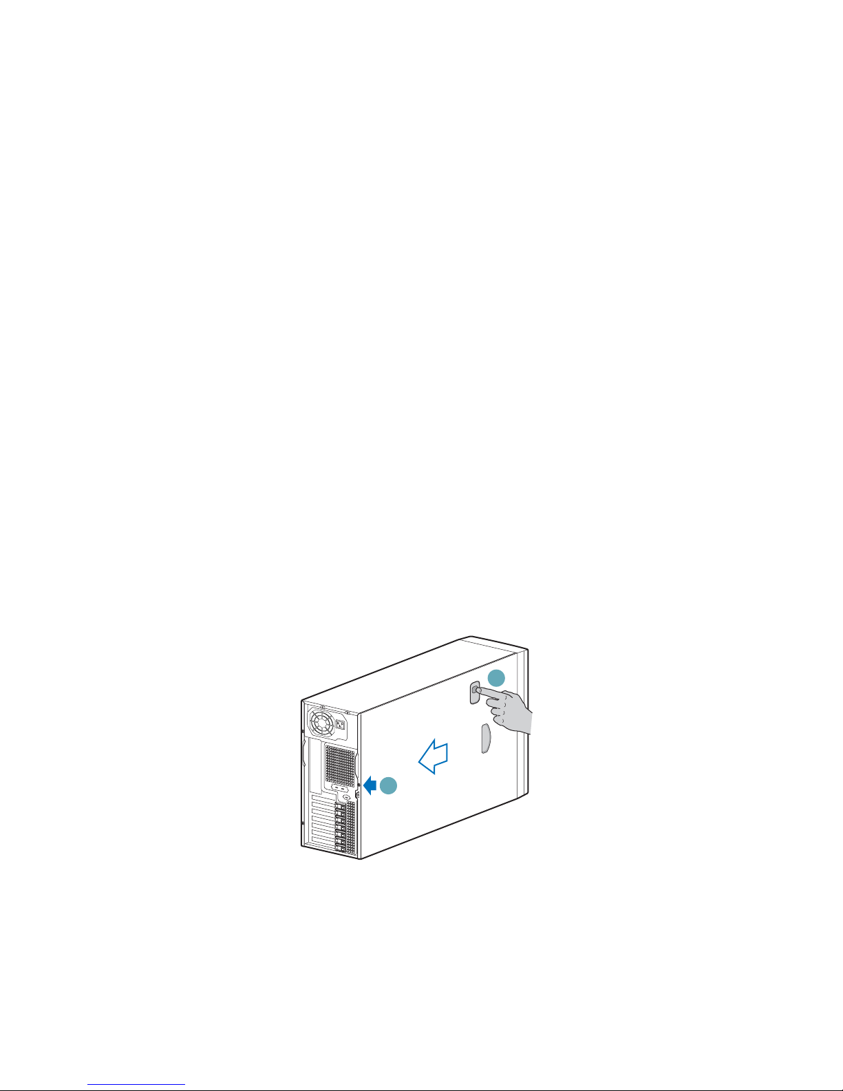
Remove Access Cover
1. Unplug all power and peripheral cables from the chassis.
2. If necessary , remove shipping screw from the back of the chassis cover (see letter “A”
in the following figure). Release latch (see letter “B”) and remove access cover.
Figure 1. Removing Access Cover
B
A
TP00527
2 Local Control Panel Kit Install Guide
Page 11
Local Control Panel Kit Installation Instructions
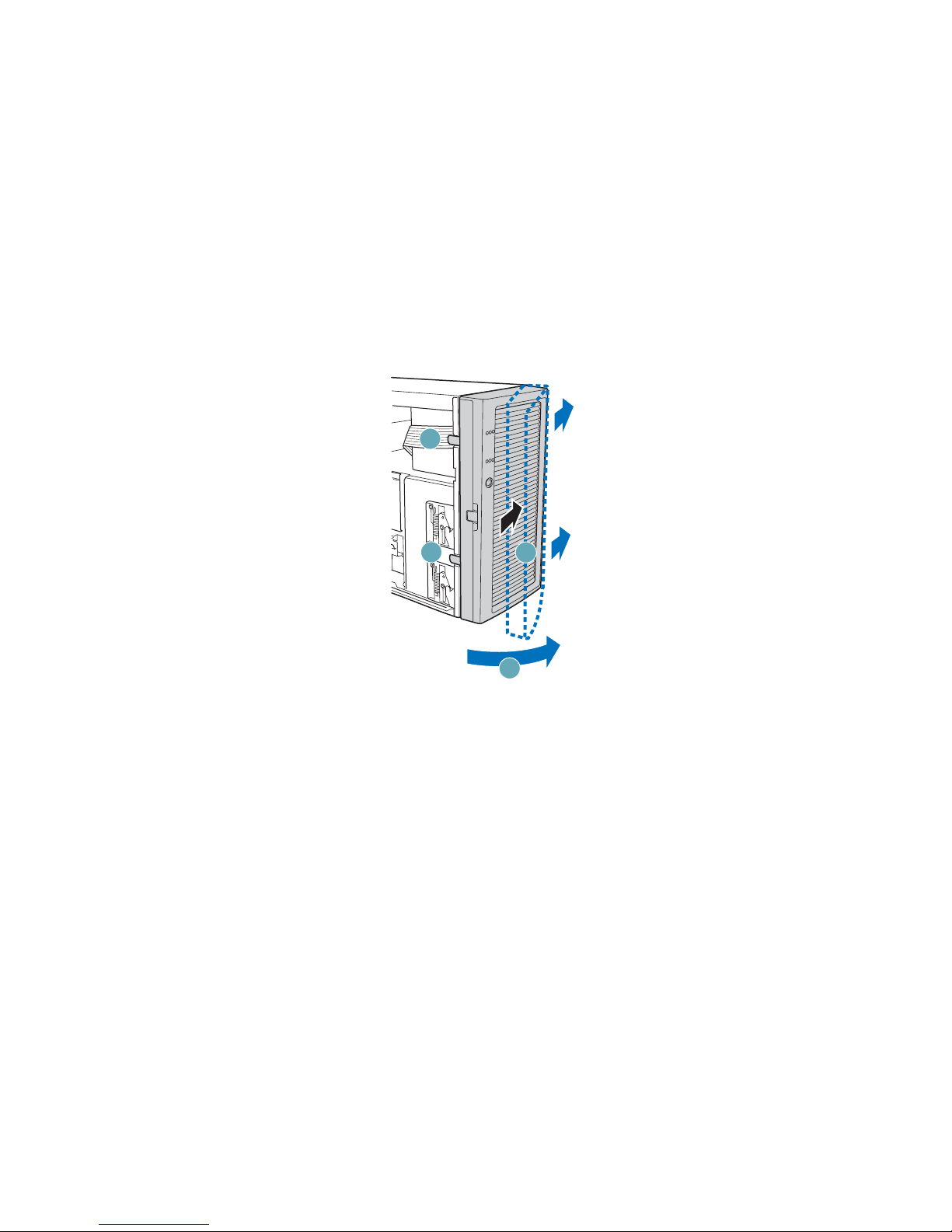
Remove Bezel Assembly
Release the two plastic tabs (see letter “A” in the following figure) on the left side of the
bezel assembly to disengage the tabs. Rotate the bezel assembly (see letter “B”) no more
than 40 degrees outward. At a 40-degree angle, push the bezel assembly away from the
chassis (see letter “C”). If the bezel assembly does not immediately disconnect from the
chassis then tap the left-hand side of the bezel assembly to disengage the bezel hooks on
the right-hand side of the chassis.
Caution: Do not rotate the bezel assembly mor e than 40 degr ees or you can damage the bezel hooks
on the right-hand side of the bezel assembly.
A
A
C
B
TP01042
Figure 2. Removing Bezel Assembly
Local Control Panel Kit Install Guide 3
Page 12

Local Control Panel Kit Installation Instructions
Remove Outer Bezel Door from Bezel Assembly
Note: The bezel assembly consists of two parts, an inner bezel door and an outer bezel door.
With one hand supporting the inner bezel door, use your other hand to push the outer bezel
door away from the inner bezel door. The outer bezel door will disengage from the inner
bezel door at the four hinges (see letter “A” in the following figure).
Caution: Only open the outer bezel door sligh tly (ab out 20 degrees) before removing it. Opening
the outer bezel door all the way before removing may break the hinges.
A
A
A
A
TP01055
Figure 3. Removing Outer Bezel Door from Bezel Assembly
4 Local Control Panel Kit Install Guide
Page 13

Remove Upper Third of Bezel Grill
Remove the upper one-third of the bezel grill by pushing grill forward.
Local Control Panel Kit Installation Instructions
TP00636
Install LCP Grill
Install new LCP grill into outer bezel door by pressing grill in from the front.
Figure 4. Removing Upper One-third of Bezel Grill
TP00637
Local Control Panel Kit Install Guide 5
Figure 5. Installing LCP Grill
Page 14

Local Control Panel Kit Installation Instructions
Remove Lowest CD-ROM/DVD Drive Filler Panel
Remove the lowest CD-ROM/DVD/Floppy drive or filler panel from chassis.
TP00638
Note:Removal of CD-ROM drive shown.
Figure 6. Removing Lowest Floppy/CD-ROM/DVD Drives or Filler Panel
6 Local Control Panel Kit Install Guide
Page 15

Install EMI Shield onto LCP Carrier
Your backplane board shipped with an EMI shield that has to be installed. Install the EMI
shield by aligning the middle tooth (see letter “A” in the following figure) with the
indentation in the side of the LCP carrier.
Local Control Panel Kit Installation Instructions
A
TP00635
Figure 7. Installing EMI Shield on LCP Carrier
Inserting LCP Carrier into Drive Bay of Server Chassis
1. Attach drive rails to LCP carrier using the top set of holes.
Figure 8. Attaching Drive Rails to LCP Carrier
TP00634
Local Control Panel Kit Install Guide 7
Page 16

Local Control Panel Kit Installation Instructions
2. Feed the LCP cable through the drive bay opening. Slide LCP carrier into server
chassis. Make sure that the drive rails are using the correct slots in the chassis.
Route LCP Cable
Route the LCP cable under the chassis fan area (along side the floppy and IDE cables) to
the corner of the server board where the LCP header is located on your Intel® server
board.
TP00639
Figure 9. Installing LCP Carrier
TP00640
Note:Intel® Server Board SE7520BD2 is shown.
8 Local Control Panel Kit Install Guide
Figure 10. Routing the LCP Cable
Page 17

Local Control Panel Kit Installation Instructions
Connect LCP Cable to LCP Header of Server Board
1. Connect the LCP cable to the LCP header on the server board.
2. For an Intel Server Board SE7520AF2, use header J1J1 on the server board.
TP00642
Figure 11. Attaching LCP Cable to Header on Intel® Server Board SE7520AF2
Local Control Panel Kit Install Guide 9
Page 18

Local Control Panel Kit Installation Instructions
3. For an Intel Server Board SE7520BD2, use header J2K8 on the server board.
TP00641
Figure 12. Attaching LCP Cable to Header on Intel® Server Board SE7520BD2
Replace Bezel Assembly
Fit the right-hand side of the inner bezel door against the right-hand side of chassis and
engage plastic bezel hooks (see letter “A” in the following figure) into raised metal slots at
chassis edge. Rotate inner bezel door inward (see letter “B”) and latch the two plastic tabs
(see letter “C”) to left-hand side of chassis. Attach outer bezel door by aligning hinges
with the right-hand side of inner bezel door and snapping into place.
10 Local Control Panel Kit Install Guide
Page 19

Local Control Panel Kit Installation Instructions
Caution: Do not attach inner bezel door to chassis at more than a 40-degree angle or you may
damage the bezel hooks at the right-hand side of the door.
C
Figure 13. Installing Inner Bezel Door
Replace Access Cover
Replace access cover and slide forward to secure cover to chassis. Replace shipping screw
(see letter “A” in the following figure) if desired.
C
A
B
TP01130
Local Control Panel Kit Install Guide 11
A
TP01000
Figure 14. Replacing Access Cover
Page 20

Local Control Panel Kit Installation Instructions
Installation Instructions for Intel® Entry Server Chassis
SC5275-E
Note: This section only applies to Local Control Panel kit installations for the Intel® Entry
Server Chassis SC5275-E. If you are installing a Local Control Panel kit into an Intel®
Server Chassis SC5300/SC5400, follow the instructions under “Installation Instructions
for Intel® Server Chassis SC5300/SC5400” on page 2. If you are installing a Local
Control Panel kit into an Intel® Entry Server Chassis SC5299-E, follow the instructions
under “Installation Instructions for Intel® Entry Server Chassis SC5299-E” on page 19.
Remove Access Cover
When your chassis is upright (in a tower/pedestal position), and you are facing the front of
it, the access cover is on the left side.
To remove the Access Cover:
1. Power the system off and disconnect the power cord.
2. If the shipping screws are installed, remove both shipping screws (see letter “A” in the
following figure).
3. Slide the two thumb latches (see letter “B”) to the OPEN position.
4. Slide the access cover rearward and lift to remove (letter “C”).
A
B
C
B
A
TP00931
Figure 15. Removing Access Cover
12 Local Control Panel Kit Install Guide
Page 21

Remove Bezel
To remove the bezel:
1. Disengage the two bezel tabs (see letter “A” in the following figure) from the chassis.
2. Rotate the left side of bezel outward slightly (see letter “B”).
3. Disengage the latches that attach the right side of the bezel to the chassis and remove
(see letter “C”).
Local Control Panel Kit Installation Instructions
Figure 16. Removing Bezel
Remove Lowest CD-ROM/DVD Drive Filler Panel
Remove the lowest CD-ROM/DVD/floppy drive or filler panel from chassis.
Note:Removal of CD-ROM drive shown.
Figure 17. Removing Lowest Floppy/CD-ROM/DVD Drives or Filler Panel
Local Control Panel Kit Install Guide 13
Page 22

Local Control Panel Kit Installation Instructions
Install EMI Shield onto LCP Carrier
Your backplane board shipped with an EMI shield that has to be installed. Install the EMI
shield by aligning the middle tooth (see letter “A” in the following figure) with the
indentation in the side of the LCP carrier.
A
TP00635
Figure 18. Installing EMI Shield on LCP Carrier
Inserting LCP Carrier into Drive Bay of Server Chassis
1. Install the drive rails by attaching each rail with two screws to the two lower holes on
each side of the LCP carrier. Use the F holes on the drive rails.
A
TP00644
Figure 19. Installing Drive Rails to LCP Carrier
14 Local Control Panel Kit Install Guide
Page 23

2. Feed the cable in first. Slide the LCP carrier into desired 5.25-in drive bay and secure
with two screws to the front of chassis.
Route LCP Cable
Local Control Panel Kit Installation Instructions
Figure 20. Inserting LCP Carrier into Drive Bay
Route the LCP cable to the corner of the server board where the LCP header is located on
your Intel® Server Board SE7520AF2 or Intel® Server Board SE7520BD2.
TP00646
Figure 21. Routing LCP Cable in Intel® Entry Server Chassis SC5275-E
Local Control Panel Kit Install Guide 15
Page 24

Local Control Panel Kit Installation Instructions
Connect LCP Cable to LCP Header on Server Board
1. Connect the LCP cable to the LCP header on the server board.
2. For an Intel® Server Board SE7520AF2, use header J1J1 on the server board.
TP00648
Figure 22. Attaching LCP Cable to Header on Intel® Server Board SE7520AF2
16 Local Control Panel Kit Install Guide
Page 25

Local Control Panel Kit Installation Instructions
3. For an Intel® Server Board SE7520BD2, use header J2K8 on the server board.
TP00647
Figure 23. Attaching LCP Cable to Header on Intel® Server Board SE7520BD2
Replace Bezel
1. If necessary, remove filler panel from bezel that corresponds to the position of the
LCP carrier.
2. Engage the three clips (see letter “A” in the following figure) at the right edge of the
bezel with the corresponding latches on the right side of the chassis.
3. Rotate the left side of bezel towards the chassis (see letter “B”).
Local Control Panel Kit Install Guide 17
Page 26

Local Control Panel Kit Installation Instructions
4. Snap the two bezel tabs (see letter “C”) into their corresponding recesses at left edge
of chassis.
Figure 24. Installing Bezel
Replace Access Cover
To replace the access cover:
1. Position access cover on chassis (see letter “A” in the following figure).
2. Slide the two thumb latches (see letter “B”) to the CLOSED position.
3. (optional) Replace shipping screws (see letter “C”).
Caution: This chassis must be operated with the access cover installed to ensure proper cooling.
C
B
A
B
C
TP00935
Figure 25. Replacing Access Cover
18 Local Control Panel Kit Install Guide
Page 27

Local Control Panel Kit Installation Instructions
Installation Instructions for Intel® Entry Server Chassis
SC5299-E
Note: This section only applies to Local Control Panel kit installations for the Intel® Entry
Server Chassis SC5299-E. If you are installing a Local Control Panel kit into an Intel®
Server Chassis SC5300/SC5400, follow the instructions in “Installation Instructions for
Intel® Server Chassis SC5300/SC5400” on page 2. If you are installing a Local Control
Panel kit into an Intel® Entry Server Board SC5275-E, follow the instructions in
“Installation Instructions for Intel® Entry Server Chassis SC5275-E” on page 12.
Remove Access Cover
When your chassis is upright (in a tower/pedestal position), and you are facing the front of
it, the access cover is on the left side.
To remove the Access Cover:
1. Power the system off and disconnect the power cord.
2. If the shipping screws are installed, remove both shipping screws (see letter “A” in the
following figure).
3. Slide the two thumb latches (see letter “B”) to the OPEN position.
4. Slide the access cover rearward and lift to remove (letter “C”).
Remove Bezel
A
B
C
A
Figure 26. Removing Access Cover
TP00559
To remove the bezel:
1. Disengage the two bezel tabs (see letter “A” in the following figure) from the chassis.
Local Control Panel Kit Install Guide 19
Page 28

Local Control Panel Kit Installation Instructions
2. Rotate the left side of bezel outward slightly (see letter “B”).
3. Disengage the latches that attach the right side of the bezel to the chassis and remove
(see letter “C”).
A
A
C
C
C
B
TP02034
Figure 27. Removing Bezel
Remove Lowest CD-ROM/DVD Drive Filler Panel
Remove the lowest CD-ROM/DVD/floppy drive or filler panel from chassis.
AF00566
Note:Removal of CD-ROM drive shown.
Figure 28. Removing Lowest Floppy/CD-ROM/DVD Drives or Filler Panel
20 Local Control Panel Kit Install Guide
Page 29

Install EMI Shield onto LCP Carrier
Your backplane board shipped with an EMI shield that has to be installed. Install the EMI
shield by aligning the middle tooth (see letter “A” in the following figure) with the
indentation in the side of the LCP carrier.
Local Control Panel Kit Installation Instructions
A
TP00635
Figure 29. Installing EMI Shield on LCP Carrier
Local Control Panel Kit Install Guide 21
Page 30

Local Control Panel Kit Installation Instructions
Inserting LCP Carrier into Drive Bay of Server Chassis
Slide the LCP carrier into the desired 5.25-in drive bay. Feed the cable in first.
AF00567
Route LCP Cable
Route the LCP cable to the corner of the server board where the LCP header is located on
your Intel® Server Board S5000VSA, Intel® Server Board S5000PSL or Intel® Server
Board S5000XVN.
Figure 30. Inserting LCP Carrier into Drive Bay
AF00568
22 Local Control Panel Kit Install Guide
Figure 31. Routing LCP Cable
Page 31

Local Control Panel Kit Installation Instructions
Connect LCP Cable to LCP Header on Server Board
1. Connect the LCP cable to the LCP header on the server board.
2. For an Intel® Server Board S5000VSA, use header J1J6 on the server board.
AF00569
Figure 32. Attaching LCP Cable to Header on Intel® Server Board S5000VSA
3. For an Intel® Server Board S5000PSL or Intel® Server Board S5000XVN, use
header J2J1 on the server board.
AF00570
Figure 33. Attaching LCP Cable to Header on Intel® Server Board S5000PSL or Intel®
Server Board XVN
Local Control Panel Kit Install Guide 23
Page 32

Local Control Panel Kit Installation Instructions
Replace Bezel
1. If necessary, remove filler panel from bezel that corresponds to the position of the
LCP carrier.
2. Line up the three clips (see letter “A” in the following figure) at the right edge of the
bezel with the corresponding latches on the right side of the chassis.
3. Engage the clips with the slots (see letter “B”).
4. Rotate the left side of bezel towards the chassis (see letter “C”).
5. Snap the two bezel tabs (see letter “D”) into their corresponding recesses at the left
edge of chassis front panel.
D
A
D
C
Figure 34. Installing Bezel
A
A
A
B
TP02035
24 Local Control Panel Kit Install Guide
Page 33

Local Control Panel Kit Installation Instructions
Replace Access Cover
To replace the access cover:
1. Slide the access cover on the chassis and latch securely (see letter “A” in the
following figure).
2. (optional) Replace shipping screws (see letter “B”).
Caution: This chassis must be operated with the access cover installed to ensure proper cooling.
B
A
B
TP00831
Figure 35. Replacing Access Cover
Local Control Panel Kit Install Guide 25
Page 34

Local Control Panel Kit Installation Instructions
26 Local Control Panel Kit Install Guide
 Loading...