

Intel SC5100 - Server Chassis Rack Optimized Hot Swap Redundant Pwr, SC2100, SC5200 Installation Manual
Page 1

®
Intel
SC5100 and SC5200 Rack Kit
Installation Guide
Order Number: A58842-005
Page 2

Disclaimer:
Information in this document is provided in connection with Intel
estoppel or otherwise, to any intellectual property rights is granted by this document. Except as provided in
Intel’s Terms and Conditions of Sale for such products, Intel assumes no liability whatsoever, and Intel
disclaims any express or implied warranty, relating to sale and/or use of Intel products including liability or
warranties relating to fitness for a particular purpose, merchantability, or infringement of any patent, copyright
or other intellectual property right. Intel products are not designed, intended or authorized for use in any
medical, life saving, or life sustaining applications or for any other application in which the failure of the Intel
product could create a situation where personal injury or death may occur. Intel may make changes to
specifications and product descriptions at any time, without notice.
Intel is a registered trademark of Intel Corporation or its subsidiaries in the United States and other countries.
†
Other names and brands may be claimed as the property of others.
Copyright Intel Corporation 2001, 2002. All rights reserved.
®
products. No license, express or implied, by
Page 3

Contents
Safety Guidelines
Server Precautions............................................................................................................... 5
Equipment Rack Precautions ............................................................................................... 6
Rack Installation Procedures
Kit Contents.......................................................................................................................... 9
Remove Feet...................................................................................................................... 10
Remove Top Cover ............................................................................................................ 11
Remove 5 ¼-Inch Devices.................................................................................................. 12
Remove Door.....................................................................................................................14
Remove Bezel....................................................................................................................16
Remove EMI Covers .......................................................................................................... 17
Remove Side Covers.......................................................................................................... 18
Remove the Right Side Cover.................................................................................... 18
Remove the Plastic or Epac System Fan Holder........................................................ 19
Remove the Right Side Cover.................................................................................... 19
Install Side Covers.............................................................................................................. 20
Install the Right Side Cover........................................................................................ 20
Install the Left Side Cover.......................................................................................... 21
Install the Epac or Plastic Fan Holder ........................................................................ 21
Remove the Bottom Cover ................................................................................................. 21
Install the Bottom Cover ..................................................................................................... 21
Install 5 ¼-Inch Devices into the Reorientation Bracket...................................................... 22
Install the 5 ¼-Inch Reorientation Bracket .......................................................................... 23
Install Bezel........................................................................................................................ 24
Install Screw Plate.............................................................................................................. 27
Install Front Cover .............................................................................................................. 28
Install Top Cover ................................................................................................................ 29
Install Handles and Rails .................................................................................................... 30
Figures
1. Removing the Feet .................................................................................................... 10
2. Removing the Cover.................................................................................................. 11
3. Removing a 5 ¼-Inch Device..................................................................................... 12
4. Removing Slide Rails................................................................................................. 13
5. Removing the Hinge Pins .......................................................................................... 14
6. Removing the Hinge Plate ......................................................................................... 15
7. Removing the Bezel................................................................................................... 16
8. Removing the EMI Covers ......................................................................................... 17
9. Removing the Right Side Cover................................................................................. 18
10. Installing the Right Side Cover................................................................................... 20
11. Installing 5 ¼-Inch Devices........................................................................................ 22
12. Installing the 5 ¼-Inch Reorientation Bracket............................................................. 23
13. Installing the Chassis Intrusion Lock.......................................................................... 24
14. Moving the Serial Port Cable ..................................................................................... 25
iii
Page 4

15. Installing the Bezel..................................................................................................... 26
16. Installing the Screw Plate........................................................................................... 27
17. Installing the Front Cover........................................................................................... 28
18. Installing the Top Cover............................................................................................. 29
19. Installing the Handles ................................................................................................ 30
20. Removing the Smallest Rail....................................................................................... 30
21. Attaching the Rail to the Chassis ............................................................................... 31
22. Rails Installed in a Rack............................................................................................. 31
23. Installing the Server into a Rack ................................................................................ 32
iv Intel SC5100 and SC5200 Rack Kit Installation Guide
Page 5

Safety Guidelines
Before you remove a server cover, observe these safety guidelines:
• Only technically qualified personnel should integrate the server.
• Turn off all peripheral devices connected to the server.
• Turn off the server using the push-button on/off power switch on the front panel of the server,
and unplug the AC power cord from the power supply or wall outlet.
• Label and disconnect all peripheral cables attached to the I/O panel on the back of the server.
• Provide some electrostatic discharge (ESD) protection by wearing an antistatic wrist strap
attached to chassis ground of the server—any unpainted metal surface—when handling
components.
Server Precautions
WARNINGS
SERVER POWER ON/OFF: The push-button on/off power switch on the
front panel of the server does not
power from the server, you must unplug the AC power cord from either
the power supply or wall outlet.
turn off the AC power. To remove AC
H
AZARDOUS CONDITIONS—POWER SUPPLY: Hazardous voltage,
current, and energy levels are present inside the power supply enclosure.
There are no user-serviceable parts inside it; servicing should only be
done by technically qualified personnel.
AZARDOUS CONDITIONS—DEVICES AND CABLES: Hazardous electrical
H
conditions may be present on power, telephone, and communication
cables. Turn off the server and disconnect telecommunications systems,
networks, modems, and the power cord attached to the server before
opening it. Otherwise, personal injury or equipment damage can result.
A
VOID INJURY: To avoid personal injury when unpacking the server,
use only a mechanical assist unit to lift it off the shipping pallet.
Use only a hand-truck or other mechanical assist unit to move the server
from one location to another.
5
Page 6

CAUTIONS
ELECTROSTATIC DISCHARGE (ESD) AND ESD PROTECTION: ESD can
damage disk drives, add-in boards, and other components. This server can
withstand normal levels of environmental ESD while hot-swapping SCSI
hard disk drives. However, we recommend doing all procedures in this
manual only at an ESD-protected workstation. If one is not available, you
can provide some ESD protection by wearing an antistatic wrist strap
attached to chassis ground of the server—any unpainted metal
surface—when handling components.
ANDLING BOARDS AND MODULES: Boards and modules can be extremely
H
sensitive to ESD and always require careful handling. After removing a
board or module from its protective wrapper or from the server, place it
component-side up on a nonconductive, static-free surface. If you place the
baseboard on a conductive surface, the battery leads can short out. If they
do, this will result in a loss of CMOS data and will drain the battery. Do not
slide a board or module over any surface.
ERVER COOLING AND AIRFLOW: Operating the server with the covers
S
removed can damage the server components. For proper cooling and airflow,
always replace the covers before turning on the server.
Equipment Rack Precautions
WARNINGS
ANCHOR THE EQUIPMENT RACK: The equipment rack must be anchored
to an unmovable support to prevent it from falling over when one or
more servers are extended in front of it on slide assemblies. The anchors
must be able to withstand a force of up to 113 kg (250 lbs.). You must
also consider the weight of any other device installed in the rack.
AIN AC POWER DISCONNECT: You are responsible for installing an
M
AC power disconnect for the entire rack unit. This main disconnect
must be readily accessible, and it must be labeled as controlling power to
the entire unit, not just to the server(s).
G
ROUNDING THE RACK INSTALLATION: To avoid the potential for an
electrical shock hazard, you must include a third wire safety grounding
conductor with the rack installation. If server power cords are plugged
into AC outlets that are part of the rack, then you must provide proper
grounding for the rack itself. If server power cords are plugged into
wall AC outlets, the safety grounding conductor in each power cord
provides proper grounding only for the server. You must provide
additional, proper grounding for the rack and other devices installed
in it.
6 Intel SC5100 and SC5200 Rack Kit Installation Guide
Page 7

OVERCURRENT PROTECTION: The server is designed for an AC line
voltage source with up to 20 amperes of overcurrent protection. If the
power system for the equipment rack is installed on a branch circuit
with more than 20 amperes of protection, you must provide
supplemental protection for the server.
CAUTIONS
Temperature: The operating temperature of the server, when installed in an
equipment rack, must not go below 5 °C (41 °F) or rise above 35 °C (95 °F).
Extreme fluctuations in temperature can cause a variety of problems in your
server.
Ventilation: The equipment rack must provide sufficient airflow to the front
of the server to maintain proper cooling. Depending on the configuration of
the server, it must also include ventilation sufficient to exhaust between
1750 BTU's and 3000 BTU’s per hour. The rack selected and the ventilation
provided must be suitable to the environment in which the server will be
used.
Safety Guidelines 7
Page 8

8 Intel SC5100 and SC5200 Rack Kit Installation Guide
Page 9

Rack Installation Procedures
This manual describes the procedure to convert an Intel® SC5100 or SC5200 server chassis from
the pedestal configuration to the rack configuration.
In the following procedures, chassis directions (top, bottom, left, right) refer to a chassis in rack
orientation when you are facing the front of the chassis. Observe the safety and ESD precautions at
the beginning of this manual.
Kit Contents
• Two unpainted access covers (SC5100 and SC5200 Base use the access cover without a fan
access door; SC5200 HSRP uses the access cover with a fan access door)
• One unpainted left side cover with rack mounting holes and one right side cover with rack
mounting holes
• One unpainted bottom cover
• Rack bezel assembly
• Bag of mounting hardware
• This manual
• Rail kit
• Rack handles
• 5 ¼ bay reorientation bracket
✏
NOTE
Your chassis is designed to be compatible with the EIA-310-d rack standard.
Be sure to select a rack cabinet enclosure that is EIA-310-d compliant. For
additional compatibility and rack cabinet selection information, see
http://support.intel.com/support/motherboards/server/chassis/sc5100
or
http://support.intel.com/support/motherboards/server/chassis/sc5200
9
Page 10
Remove Feet
1. Place the chassis on a workbench so the feet hang over the side.
2. Remove the four screws that attach the rear foot to the chassis and remove the foot.
3. Remove the four screws that hold the front foot to the chassis and remove the foot.
C
A
A. Workbench
B. Feet
C. Screw
* Some chassis details shown may different in your chassis.
Figure 1. Removing the Feet
B
OM12024
10 Intel SC5100 and SC5200 Rack Kit Installation Guide
Page 11

Remove Top Cover
1. Loosen the two thumbscrews that attach the top cover to the chassis.
2. Slide the cover backward a short distance, until it stops.
3. Pull the entire cover outward, straight away from the chassis, to disengage the rows of tabs
from the notches in the top and bottom edges of the chassis. Set the cover aside.
OM11929
* Some chassis details shown may different in your chassis.
Figure 2. Removing the Cover
Rack Installation Procedures 11
Page 12

Remove 5 ¼-Inch Devices
1. Disconnect the data and power cables from the device.
2. Remove and save the two screws that hold the slide rails to the chassis.
C
D
B
A
OM13721
A. 5 ¼-inch device
B. Screw
C. Data cable
D. Power cable
Figure 3. Removing a 5 ¼-Inch Device
12 Intel SC5100 and SC5200 Rack Kit Installation Guide
Page 13

3. Remove and save the screws that attach the slide rails to the device.
Figure 4. Removing Slide Rails
OM12026
Rack Installation Procedures 13
Page 14

Remove Door
1. Move the chassis so the door hangs over the edge of your workbench.
2. Open the door.
3. Press the plastic clip in towards the chassis.
4. Pull the hinge pin out with one hand while supporting the door with the other.
5. Slide the door to the left to remove it from the other hinge pin.
6. Remove the hinge pins and save for future use.
A
B
14 Intel SC5100 and SC5200 Rack Kit Installation Guide
A. Plastic clip
B. Hinge pin
Figure 5. Removing the Hinge Pins
OM13729
Page 15

7. Remove and save the four screws attaching the hinge plate to the chassis.
8. Remove the hinge plate.
OM13722
Figure 6. Removing the Hinge Plate
Rack Installation Procedures 15
Page 16

Remove Bezel
1. Press the tab up.
2. Slide the bezel to the right.
3. Remove the bezel from the chassis.
A
A. Tab
Figure 7. Removing the Bezel
OM13724
16 Intel SC5100 and SC5200 Rack Kit Installation Guide
Page 17

Remove EMI Covers
1. Remove and save the two screws that attach the EMI covers to the chassis.
2. Remove all of the EMI covers. There will be one thin cover and up to three wider covers. Do
not remove any of the hard drive carriers.
A
OM13723
A. EMI covers
Figure 8. Removing the EMI Covers
Rack Installation Procedures 17
Page 18

Remove Side Covers
Remove the Right Side Cover
1. Remove and save the screw at the rear of the chassis.
2. Pull up on the black clip.
3. Remove and save the black clip.
4. Slide the cover backwards and remove it.
B
C
A
D
A. Screw
B. Pull the clip up
C. Remove the clip
D. Slide the cover off
Figure 9. Removing the Right Side Cover
OM13725
18 Intel SC5100 and SC5200 Rack Kit Installation Guide
Page 19

Remove the Plastic or Epac System Fan Holder
• For the SC5100 Chassis and the SC5200 Base Chassis: Remove the epac holding the
system fans.
• For the SC5200 HSRP Chassis:
1. Remove the plastic fan holder by removing the 3 retention screws that connect it to the
baseplate.
Remove the Right Side Cover
1. Remove and save the screw at the rear of the chassis.
2. Pull up on the black clip.
3. Remove and save the black clip.
4. Slide the cover backwards and remove it.
Rack Installation Procedures 19
Page 20

Install Side Covers
Install the Right Side Cover
1. Slide the new cover into position.
2. Insert the black clip.
3. Press the clip down.
4. Insert and tighten the screw you removed earlier.
B
C
A
A
A. Slide the cover on
B. Install the clip
C. Push the clip down
Figure 10. Installing the Right Side Cover
OM13726
20 Intel SC5100 and SC5200 Rack Kit Installation Guide
Page 21

Install the Left Side Cover
1. Slide the new cover into position.
2. Insert the black clip.
3. Press the clip down.
4. Insert and tighten the screw you removed earlier.
Install the Epac or Plastic Fan Holder
• For the SC5100 Chassis and the SC5200 Base Chassis: Re-install the epac holding the
system fans.
• For the SC5200 HSRP Chassis: Re-install the plastic fan holder by re-installing it in the system
and tightening the 3 retention screws that connect it to the baseplate.
Remove the Bottom Cover
1. Remove and save the two screws that attach the top cover to the chassis.
2. Slide the cover backward a short distance, until it stops.
3. Pull the entire cover outward, straight away from the chassis, to disengage the rows of tabs
from the notches in the top and bottom edges of the chassis. Set the cover aside.
Install the Bottom Cover
1. Place the new cover so the tabs go into the slots on the server. The cover should be flush
against the chassis.
2. Slid the cover forward until it stops.
3. Tighten the two screws into the rear of the chassis.
Rack Installation Procedures 21
Page 22

Install 5 ¼-Inch Devices into the Reorientation Bracket
1. Remove the two screws that hold the EMI shield in place.
2. Remove the EMI shield.
3. Slide the device into the bracket.
4. Insert and tighten the four screws removed when you removed the slide rails.
B
A
C
A. 5 ¼-inch device
B. Screws that hold the device
C. EMI shields
D. Screws that hold the EMI shields
Figure 11. Installing 5 ¼-Inch Devices
D
OM12029
22 Intel SC5100 and SC5200 Rack Kit Installation Guide
Page 23

Install the 5 ¼-Inch Reorientation Bracket
1. Slide the bracket into the chassis.
2. Insert and tighten five screws.
3. Connect data and power cables to the devices.
C
B
A. Screw
B. Data cable
C. Power cable
Figure 12. Installing the 5 ¼-Inch Reorientation Bracket
Rack Installation Procedures 23
A
OM13720
Page 24

Install Bezel
1. Position the chassis intrusion switch lock.
2. Using a Philips
†
screwdriver, rotate the switch lock ½ turn clockwise.
A
B
D
A. Philips screwdriver
B. Chassis intrusion switch lock
C. Direction of rotation
D. Chassis intrusion switch
C
OM13730
Figure 13. Installing the Chassis Intrusion Lock
24 Intel SC5100 and SC5200 Rack Kit Installation Guide
Page 25

3. If desired, move the serial port cable to the front and remove the serial port filler panel (B).
C
E
D
A
B
OM13732
A. Bezel
B. Serial port filler panel
C. Rear panel serial port
D. Front panel serial port
E. Serial port cable
Figure 14. Moving the Serial Port Cable
Rack Installation Procedures 25
Page 26

4. Position the bezel. Make sure all of the plastic tabs are aligned with their holes.
5. Slide it to the left until the tab locks in place.
A
A. Tab
Figure 15. Installing the Bezel
OM13724
26 Intel SC5100 and SC5200 Rack Kit Installation Guide
Page 27

Install Screw Plate
1. Position the Screw Plate.
2. Insert and tighten the four screws you removed when you removed the door hinge plate.
Figure 16. Installing the Screw Plate
OM13728
Rack Installation Procedures 27
Page 28

Install Front Cover
1. For each 5 ¼-inch peripheral, remove the corresponding plastic cover.
2. If you have a hot swap bay installed, remove that plastic cover.
3. Position the bezel by sliding the tabs on the top under the bezel.
4. Tighten the thumbscrews.
Figure 17. Installing the Front Cover
OM13731
28 Intel SC5100 and SC5200 Rack Kit Installation Guide
Page 29

Install Top Cover
The Rack Kit contains two unpainted top covers. The SC5100 server chassis and the SC5200 Base
server chassis use the top cover without a fan access door. The SC5200 HSRP server chassis uses
the top cover with a fan access door.
1. Place the cover so the tabs go into the slots on the server. The cover should be flush against the
chassis.
2. Slid the cover forward until it stops.
3. Tighten the two captive screws into the rear of the chassis.
Figure 18. Installing the Top Cover
OM11928
Rack Installation Procedures 29
Page 30

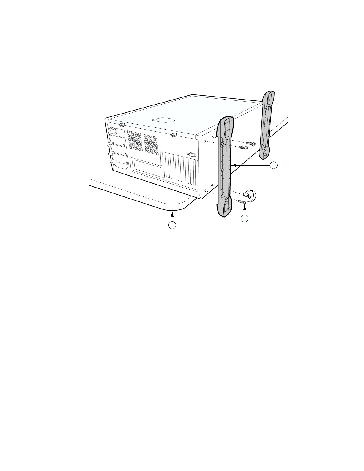
Install Handles and Rails
1. Using two screws for each handle, attach the handles to the chassis.
A. Handle
B. Screw
Figure 19. Installing the Handles
B
A
OM13733
2. Fully extend the rails.
3. Remove the smallest, inner-most rail.
Figure 20. Removing the Smallest Rail
OM12541
30 Intel SC5100 and SC5200 Rack Kit Installation Guide
Page 31

4. Position the rail.
5. Insert and tighten four screws.
6. Install the outer rail into the rack.
a. If your rack has square holes, mount the rail brackets on the inside of the rack pillar. Put
the square hook through the desired hole and secure the bracket with an M4 x 8mm screw
included with your chassis.
b. If your rack has round holes, mount the rail brackets on the outside of the rack pillar. Use
mounting hardware appropriate for your rack. Refer to your rack documentation for
mounting information.
7. Do the same for the other rail.
Figure 21. Attaching the Rail to the Chassis
OM13734
A
C
A. Rack with square holes
B. Rack with round holes
C. Anti-rotation tab
Figure 22. Rails Installed in a Rack
B
OM13735
Rack Installation Procedures 31
Page 32

NOTE
✏
Your rack may vary from the illustration. Refer to your rack documentation
for information specific to your rack.
8. Check to ensure that the slide rail assemblies are mounted perpendicular to the rack monting
flange and that the assemblies are parallel to each other.
9. Hold the chassis so the rails on the chassis engage the rails in your rack. You will need
someone to help you at this point.
10. Disengage the locking tab on each rail and slide the server into the rack.
CAUTION
If you encouter resistance while sliding the server into the rack, remove the
server from the rack and re-align the rails.
OM13736
Figure 23. Installing the Server into a Rack
11. Secure the server to the rack. See your rack documentation for more information.
32 Intel SC5100 and SC5200 Rack Kit Installation Guide
 Loading...