

Page 1

SC450NX MP
Server System
Product Guide
Order Number: 700059-002
Page 2

Disclaimer
Intel Corporation (Intel) makes no warranty of any kind with regard to this material, including, but not limited to, the implied
warranties of merchantability and fitness for a particular purpose. Intel assumes no responsibility for any errors that may
appear in this document. Intel makes no commitment to update nor to keep current the information contained in this
document. No part of this document may be copied or reproduced in any form or by any means without prior written
consent of Intel.
An Intel product, when used in accordance with its associated documentation, is "Year 2000 Capable" when, upon
installation, it accurately stores, displays, processes, provides, and/or receives date data from, into, and between the
twentieth and twenty-first centuries, including leap year calculations, provided that all other technology used in combination
with said product properly exchanges date data with it.
†
Third party brands and names are the property of their respective owners.
Copyright © 1998, Intel Corporation.
Page 3

Contents
Part I: User’s Guide
........................................................................................................... 9
1 Chassis Description
Chassis Feature Summary..................................................................................................12
Chassis Front Controls and Indicators........................................................................13
Chassis Back Controls and Features..........................................................................14
Chassis Side View......................................................................................................15
Peripherals..........................................................................................................................16
3.5-inch Diskette Drive................................................................................................16
3.5-inch Hard Drive Bays............................................................................................16
5.25-inch Removable Media Device Bays...................................................................16
Power Supplies ...................................................................................................................17
System Cooling...................................................................................................................17
Chassis Security..................................................................................................................17
2 Baseboard Description
Baseboard Features............................................................................................................19
Baseboard Connector and Component Locations.......................................................20
Processor...................................................................................................................21
Memory .....................................................................................................................22
Peripherals..........................................................................................................................24
Super I/O Chip............................................................................................................24
Add-in Board Slots ..............................................................................................................24
Video...................................................................................................................................25
SCSI Controller ...................................................................................................................25
IDE Controller......................................................................................................................26
Keyboard and Mouse..........................................................................................................26
Server Management............................................................................................................27
Baseboard Management Controller (BMC).................................................................27
System Security..................................................................................................................28
Mechanical Locks and Monitoring...............................................................................28
Software Locks via the SSU or BIOS Setup ...............................................................28
3 Configuration Software and Utilities
Hot Keys .............................................................................................................................31
Power-on Self Test (POST).................................................................................................32
Using BIOS Setup...............................................................................................................33
Record Your Setup Settings .......................................................................................33
If You Cannot Access Setup.......................................................................................33
Starting Setup.............................................................................................................33
Setup Menus ..............................................................................................................34
Main Menu..................................................................................................................35
Advanced Menu..........................................................................................................37
Security Menu.............................................................................................................41
iii
Page 4

Server Menu...............................................................................................................42
Boot Menu..................................................................................................................43
Exit Menu ...................................................................................................................45
Using the System Setup Utility (SSU)..................................................................................46
When to Run the SSU ................................................................................................46
What You Need to Do.................................................................................................47
Running the SSU........................................................................................................47
Customizing the SSU..................................................................................................49
Launching a Task .......................................................................................................49
Resource Configuration Add-in (RCA) Window...........................................................50
Multiboot Options Add-in ............................................................................................51
Security Add-in...........................................................................................................52
System Event Log (SEL) Viewer Add-in .....................................................................52
Sensor Data Record (SDR) Manager Add-In..............................................................54
Field Replaceable Unit (FRU) Manager Add-In...........................................................55
Exiting the SSU ..........................................................................................................57
Emergency Management Port (EMP) Console....................................................................57
How the EMP Console Works.....................................................................................58
EMP Console Requirements.......................................................................................60
Setting Up the Server for the EMP..............................................................................60
Main EMP Console Window .......................................................................................61
Server Control Operations..........................................................................................63
Phonebook .................................................................................................................65
Management Plug-ins.................................................................................................66
FRU and SDR Load Utility...................................................................................................69
When to Run the FRUSDR Load Utility ......................................................................69
What You Need to Do.................................................................................................69
How You Use the FRUSDR Load Utility......................................................................69
Cleaning Up and Exiting .............................................................................................73
Upgrading the BIOS............................................................................................................74
Preparing for the Upgrade..........................................................................................74
Upgrading the BIOS....................................................................................................75
Recovering the BIOS..................................................................................................76
Changing the BIOS Language....................................................................................76
Using the Firmware Update Utility.......................................................................................76
Running the Firmware Update Utility ..........................................................................77
Installing Video Drivers........................................................................................................77
Using the Symbios SCSI Utility............................................................................................77
Running the SCSI Utility .............................................................................................77
4 Exchanging SCSI Hard Drives and Power Supplies
SCSI Hard Disk Drives........................................................................................................79
Mounting a SCSI Hard Disk Drive in a Plastic Carrier.................................................79
Hot-swapping a SCSI Hard Disk Drive........................................................................80
Installing Heatsinks on High-Power Drives .................................................................82
Power Supply......................................................................................................................83
Removing a Power Supply..........................................................................................83
Installing a Power Supply............................................................................................84
iv
Page 5

Part II: Service Technician’s Guide
............................................................................85
5 Working Inside the System
Tools and Supplies Needed ................................................................................................87
Safety: Before You Remove the Access Cover..................................................................87
Warnings and Cautions.......................................................................................................88
Access Cover......................................................................................................................89
Removing the Access Cover.......................................................................................89
Installing the Access cover .........................................................................................90
Subchassis and Electronics Bay..........................................................................................90
Opening the Subchassis and Electronics Bay.............................................................90
Add-in Boards .....................................................................................................................92
Installing an Add-in Board...........................................................................................92
Removing an Add-in Board.........................................................................................93
Front Panel Board...............................................................................................................94
Removing the Front Panel Board................................................................................94
Installing the Front Panel Board..................................................................................94
Diskette Drive......................................................................................................................95
Removing the Diskette Drive ......................................................................................95
Installing the Diskette Drive ........................................................................................96
Peripheral Drives.................................................................................................................97
Drive Cabling Considerations .....................................................................................97
Installing a 5.25-inch Peripheral in the Front Bay........................................................98
Removing a 5.25-inch Peripheral from the Front Bay ...............................................101
Fans .................................................................................................................................102
Removing the System Fan Assembly.......................................................................102
Installing the System Fan Assembly.........................................................................103
Removing an Individual System Fan.........................................................................103
Installing an Individual System Fan...........................................................................105
Installing Fans for High-Power Drives.......................................................................106
6 Upgrading Baseboard Components
Tools and Supplies Needed ..............................................................................................109
Warnings and Cautions.....................................................................................................109
Baseboard.........................................................................................................................110
Removing the Baseboard .........................................................................................110
Installing the Baseboard...........................................................................................111
Memory.............................................................................................................................112
Removing the Memory Module.................................................................................112
Installing the Memory Module...................................................................................113
Removing DIMMs.....................................................................................................113
Installing DIMMs.......................................................................................................114
Processors........................................................................................................................116
Removing a Processor .............................................................................................116
Installing a Processor ...............................................................................................118
Installing Processor Tabs .........................................................................................119
Replacing the Backup Battery...........................................................................................120
v
Page 6

7 Solving Problems
Resetting the System........................................................................................................123
Initial System Startup ........................................................................................................123
Checklist...................................................................................................................123
Running New Application Software ...................................................................................124
Checklist...................................................................................................................124
After the System Has Been Running Correctly..................................................................124
Checklist...................................................................................................................124
More Problem-solving Procedures ....................................................................................125
Preparing the System for Diagnostic Testing............................................................125
Using PCDiagnostics................................................................................................125
Monitoring POST......................................................................................................126
Verifying Proper Operation of Key System Lights.....................................................126
Confirming Loading of the Operating System ...........................................................126
Specific Problems and Corrective Actions.........................................................................126
Power Light Does Not Light......................................................................................127
No Beep Codes........................................................................................................127
No Characters Appear on Screen.............................................................................127
Characters Are Distorted or Incorrect.......................................................................128
System Cooling Fans Do Not Rotate Properly..........................................................128
Diskette Drive Activity Light Does Not Light..............................................................128
Hard Disk Drive Activity Light Does Not Light...........................................................129
CD-ROM Drive Activity Light Does Not Light............................................................129
Network Problems ....................................................................................................129
PCI Installation Tips..................................................................................................129
Problems with Application Software ..................................................................................130
Bootable CD-ROM Is Not Detected...................................................................................130
Error and Informational Messages ....................................................................................130
POST Codes and Countdown Codes .......................................................................130
POST Error Codes and Messages....................................................................................134
8 Technical Reference
Connectors ........................................................................................................................138
Main Power Connector.............................................................................................139
Auxiliary Power.........................................................................................................139
Diskette Drive...........................................................................................................140
Front Panel Connector..............................................................................................141
SMM Connector........................................................................................................142
IPMB.........................................................................................................................143
VGA Video Port........................................................................................................143
Keyboard and Mouse................................................................................................144
Parallel Port..............................................................................................................144
Serial Ports A and B .................................................................................................145
Universal Serial Bus .................................................................................................145
Narrow SCSI.............................................................................................................146
Wide SCSI................................................................................................................147
IDE...........................................................................................................................148
vi
Page 7

Hard Drive LED ........................................................................................................148
ISA ...........................................................................................................................149
PCI...........................................................................................................................150
Baseboard Jumpers..........................................................................................................151
General Procedure to Change Jumper Setting.........................................................152
CMOS Clear Jumper ................................................................................................152
Password Clear Jumper ...........................................................................................153
Recovery Boot Jumper.............................................................................................153
System I/O Addresses.......................................................................................................154
Memory Map.....................................................................................................................156
Interrupts...........................................................................................................................157
Video Modes.....................................................................................................................158
A Equipment Log and Configuration Worksheets
Equipment Log .........................................................................................................163
Configuration Worksheets ........................................................................................165
Current Usage..........................................................................................................165
SSU Worksheets......................................................................................................166
B Regulatory Specifications
Regulatory and Environmental Specifications....................................................................177
Environmental Specifications....................................................................................177
Declaration of the Manufacturer or Importer.............................................................177
Safety Compliance....................................................................................................177
Electromagnetic Compatibility (EMC) .......................................................................178
C Warnings
WARNING: English (US)..................................................................................................182
AVERTISSEMENT: Français............................................................................................184
WARNUNG: Deutsch.......................................................................................................186
AVVERTENZA: Italiano....................................................................................................188
ADVERTENCIAS: Español...............................................................................................190
Index
.....................................................................................................................................193
vii
Page 8

viii
Page 9

Part I: User’s Guide
1 Chassis Description
2 Baseboard Description
3 Configuration Software and Utilities
4 Exchanging SCSI Hard Drives and Power Supplies
9
Page 10

blank page
10
Page 11
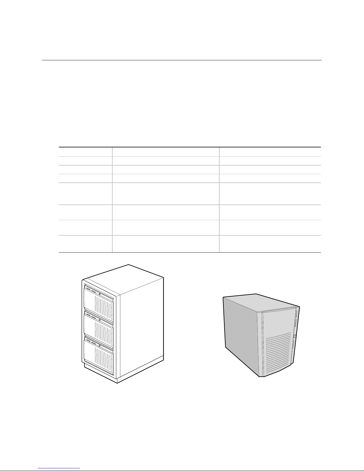
1 Chassis Description
The SC450NX MP server is designed to either stand upright (pedestal mode) or be mounted in a
rack (rack mode). Figures 1 and 2 show examples of these configurations. Before operation, you
must purchase an adapter kit to configure the server for one of the two modes. If you have already
created a pedestal server but now want to install it in a rack, you will also need an adapter kit.
If you have not already purchased a kit for your particular task, contact your customer service
representative for details. For instructions on mounting your server, see the printed
SC450NX MP Server System Rack/Pedestal Kit Installation Guide accompanying your kit.
Table 1. SC450NX MP Server Physical Specifications
Specification Pedestal Mode Rack Mode
Height 48.26 cm (19 inches) 7u
Width 31.12 cm (12.25 inches) 19 inch rack
Depth 63.5 cm (25 inches) 25 inches
Weight 38.25 kg (85 lbs) minimum configuration
45 kg (100 lbs) maximum configuration
Required front
clearance
Required rear
clearance
Required side
clearance
10 inches (inlet airflow <35 °C / 95 °F) 10 inches (inlet airflow <35 °C / 95 °F)
8 inches (no airflow restriction) 8 inches (no airflow restriction)
0.0 inches (additional side clearance
required for service)
38.25 kg (85 lbs) minimum
configuration
45 kg (100 lbs) maximum configuration
N/A
Figure 1. Equipment Rack with Three Servers Figure 2. Single Server in Pedestal Mode
OM08045
OM08000
11
Page 12

Chassis Feature Summary
The system’s galvanized metal chassis minimizes EMI and radio frequency interference (RFI).
The removable access cover is attached to the chassis with two screws. A front subchassis and an
electronics bay (at the rear of the main chassis) both rotate outward and can be removed entirely to
provide easy access to internal components. The removable front panel provides access to the
3.5- and 5.25-inch peripheral bays in the front of the chassis.
Table 2. Chassis Feature Summary
Feature Description
Drives Installed:
1.44 MB, 3.5-inch diskette drive, accessible from front subchassis.
Expansion capacity:
Three 5.25-inch-wide bays that are externally accessible, designed to hold
half-height standard removable media devices; the bays can be converted
into a single full-height bay.
Also, one externally accessible bay can hold up to six one-inch drives with an
optional SCSI backplane, or up to two drives without the backplane.
Expansion slot covers Up to eight slot covers can be used; every slot opening that does not have an
add-in board installed must have a slot cover installed.
Baseboard Form-factor, 16 × 13 inches, ATX I/O.
Power supply Up to three 400-watt power supplies with integrated cooling fans and
detachable AC power cords.
Cooling Up to 11 fans provide cooling and airflow: three system fans inside the
chassis (and three more needed only for redundant cooling), one fan for each
power supply (up to three), and two fans for cooling hard drives.
12
Page 13
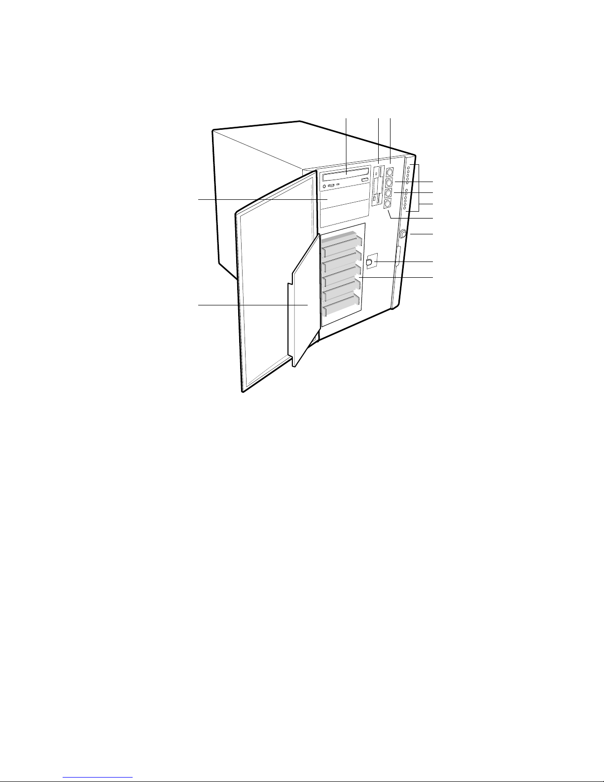
Chassis Front Controls and Indicators
L
K
ABC
D
E
F
G
H
I
J
OM08001
Figure 3. Front Controls and Indicators
A. External drive bay (5¼”); CD-ROM drive shown installed (not included)
B. Diskette drive
C. Power On/Off button (holding down this button for more than four seconds causes a
power-button override to the PIIX4E when you release the button)
D. Sleep/Service button (holding down this button for LESS THAN four seconds enters sleep
mode, which requires an ACPI-compliant OS; holding it down for MORE THAN four seconds
enters service mode, which powers down the electronics bay but leaves hot-swap and
peripheral bays running)
E. Reset button
F. Front panel LEDs (Top to bottom: top five are power on, disk bay power on, HDU activity, fan
failure, power supply failure; bottom six are hard-drive activity LEDs, labeled 0-5)
G. NMI button
H. System security lock
I. EMI shield lock
J. Internal drive bays (3½”). Five are shown installed, but maximum capacity is six.
K. Metal EMI shield
L. Expansion drive bay (5¼”)
13
Page 14
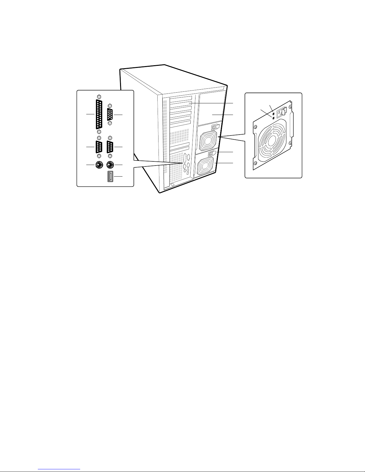
Chassis Back Controls and Features
H
A
C
B
D
I
J
E
F
K
G
Figure 4. Back Controls and Indicators
A. Parallel port
B. VGA† monitor connector
C. Serial port A, COM1
D. Serial port B, COM2
E. Mouse connector
F. Keyboard connector
G. Universal serial bus connector
H. Expansion slot covers (six slot connectors provided on baseboard)
I. Power supply bay
J. AC input power connector
K. Power supply fan
L. Power supply LED
M. Power supply failure LED (LED not lit means failure)
M
L
OM08002
14
Page 15
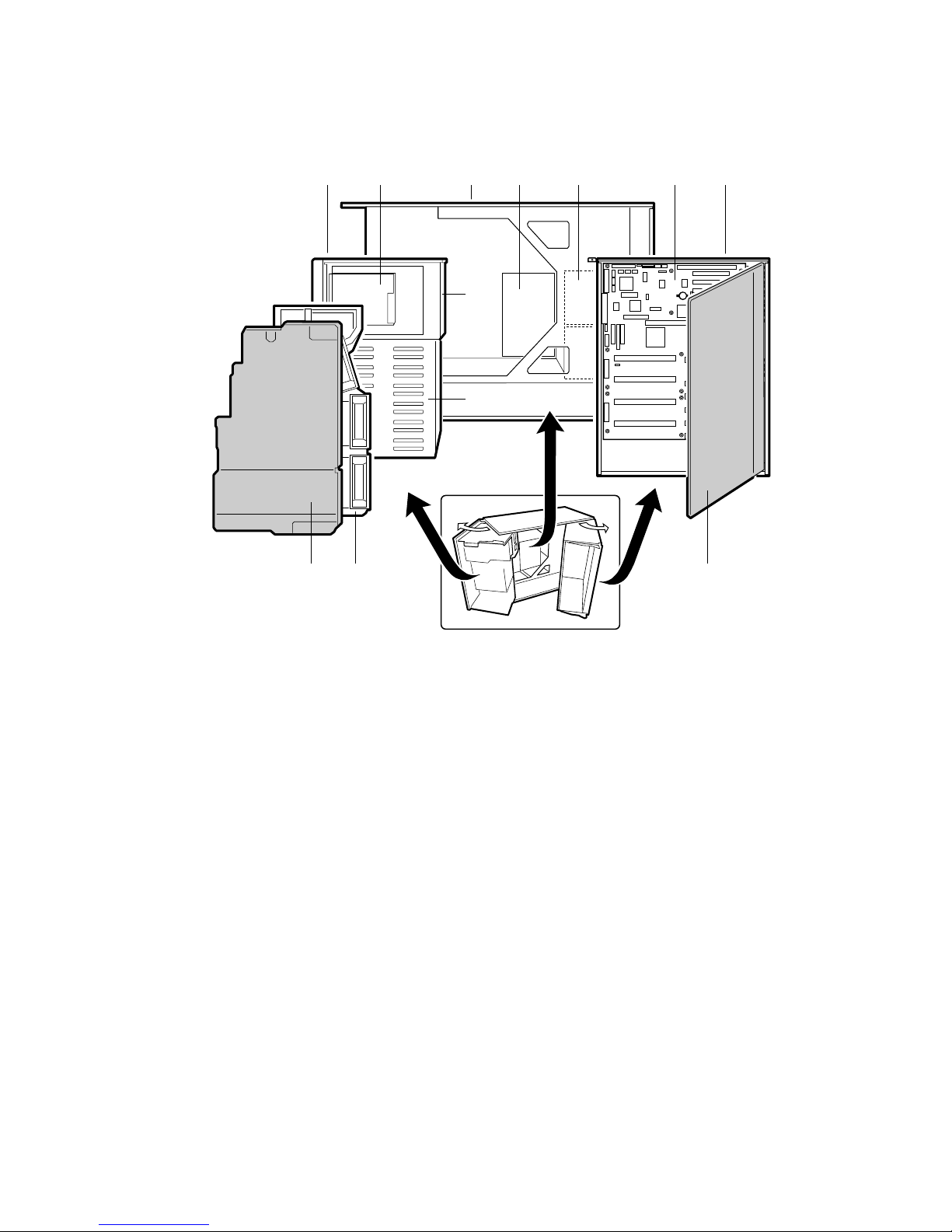
Chassis Side View
A
B
C
D
E F
G
H
I
JL K
Figure 5. Chassis Side View
A. Front swing-out subchassis
B. Diskette drive
C. Main chassis
D. Power backplane
E. Power supply(s)
F. Baseboard
G. Lift-out electronics bay
H. 5.25” device bay
I. SCSI hard drive bay
J. Foam cover
K. Foam fan housing
L. Foam fan housing cover
OM08017
15
Page 16

Peripherals
3.5-inch Diskette Drive
The 3.5-inch diskette drive in the 3.5-inch peripheral bay supports 720 KB, and 1.44 MB media.
The drive is externally accessible from the front of the system.
3.5-inch Hard Drive Bays
The chassis contains one bay for two 3.5-inch-wide (1" high or 1-5/8" high) LVDS SCSI hard
drives with internal cabling. An optional hot-swap-capable backplane can accommodate six
3.5-inch-wide (1" high) or three 3.5-inch (1-7/8" high) hard drives, which are accessed externally
from the front of the system. To upgrade to a backplane, or to upgrade your existing backplane,
you must buy a kit.
As part of the hot-swap implementation, a drive carrier is required. The drives are mounted in the
carrier with four fasteners and the carrier snaps into the chassis. Drives whose power exceeds 15
watts require heatsinks and system fans for extra cooling. These parts are available in an optional
kit.
• For information on how and when to install heatsinks, see “Installing Heatsinks on High-
Power Drives” on page 82.
• For information on how and when to install extra fans, see “Installing Fans for High-Power
Drives” on page 106.
A single metal EMI shield and plastic door cover the drive bays. A hot-docking bay is provided
for drives that are 3.5 inches wide and 1 inch high. Drives can consume up to 22 watts of power
and must be specified to run at a maximum ambient temperature of 55 °C.
The system was designed to allow the user to install a Redundant Array of Independent Disks
(RAID). A software implementation with onboard SCSI or an add-in board can be used to set up
RAID applications.
5.25-inch Removable Media Device Bays
The chassis has three 5.25-inch half-height bays that are accessible from the front of the system.
These bays are intended to provide space for tape backup or other removable devices.
You can convert the 5.25-inch bays to a single full-height bay. We recommend that you do not use
these bays for hard disk drives, because they generate EMI (increasing ESD susceptibility), and
because of inadequate cooling.
16
Page 17

Power Supplies
The chassis can be configured with one, two, or three 400-watt power supplies, each designed to
minimize EMI and RFI. Each supply operates within the following voltage ranges and is rated as
follows:
• 100-120 V∼ at 50/60 Hertz (Hz); 7.6 A maximum
• 200-240 V∼ at 50/60 Hz; 3.8 A maximum
The DC output voltages of each power supply are:
• +3.3 V at 36 A max
• +5 V at 24 A max (total combined output of +3.3 V and +5.5 V not to exceed 195 W)
• +12 V at 18.0 A with 19.0 A <10ms peak
• +24 V at 50mA
• -12 V at 0.5 A
• +5 V standby 1.5 A
Power is sourced through the power cable to the 20-pin main connectors on the baseboard.
Remote sensing signals are provided through the cable to the 14-pin auxiliary connector on the
baseboard.
System Cooling
The minimum chassis configuration includes three fans for cooling and airflow (and can accept up
to five more). The number of additional fans depends on your configuration: one fan for each
power supply (up to three) and two fans for cooling hard drives.
NOTE
✏
The access cover must be on the system for proper cooling.
Chassis Security
For information on security features on the SC450NX MP server, see “System Security” on
page 28.
17
Page 18

Blank page
18
Page 19

2 Baseboard Description
Baseboard Features
Table 3. Baseboard Features
Feature Description
Processor Installed: Up to four Pentium® II Xeon™ processors, packaged in single edge
contact (S.E.C.) cartridges and installed in 330-pin Slot 2 processor
connectors, operating at 1.8 V to 3.5 V. The baseboard's voltage regulator is
automatically programmed by the processor's VID pins to provide the required
voltage.
Includes connectors for six VRM 8.3-compliant plug-in voltage-regulator
modules.
Memory, dynamic
random access (DRAM)
Video memory (DRAM) Installed: 2 MB of video memory.
PCI Segment A bus
PCI Segment B bus
ISA bus One expansion slot for add-in boards (shared with a PCI-B slot). Embedded
Server Management Thermal/voltage monitoring and error handling.
Graphics Integrated onboard Cirrus Logic GD5480 super video graphics array
SCSI Two embedded SCSI controllers:
System I/O PS/2†-compatible keyboard and mouse ports, 6-pin DIN.
Form Factor Form-factor, 13 × 16 inches, ATX I/O.
Single plug-in module containing 64/72-bit four-way-interleaved pathway to
main memory supporting EDO DRAM.
Installed: 128 MB to 4 GB of error correcting code (ECC) memory.
PCI-A—
PCI-B—
and one embedded device:
PC-compatible support (serial, parallel, mouse, keyboard, diskette).
Front panel controls and indicators (LEDs).
(SVGA) controller.
Symbios SYM53C810AE—
support for the legacy 8-bit SCSI devices in the 5.25-inch drive bays.
Symbios SYM53C896—
SCSI controller on PCI-B bus driving one SCSI backplane in the system and
providing support for external expansion.
Advanced parallel port, supporting Enhanced Parallel Port (EPP) levels 1.7
and 1.9, ECP, compatible 25-pin.
VGA video port,15-pin.
Two serial ports, 9-pin (serial port A is the top connector).
Three expansion connectors and four embedded devices:
• Programmable interrupt device (PID)
• PCI/ISA/IDE Accelerator (PIIX4E) for PCI-to-ISA bridge, PCI IDE
interface, and Universal Serial Bus (USB) controller
• PCI video controller (Cirrus Logic GD5480)
• PCI narrow SCSI controller (Symbios
Four expansion connectors (one physically shared with the ISA slot)
• Wide Ultra/Ultra II SCSI controller (Symbios SYM53C896)
†
SYM53C810AE)
narrow SCSI controller on PCI-A bus providing
dual-channel wide LVD/SE (Ultra2/Ultra)
19
Page 20
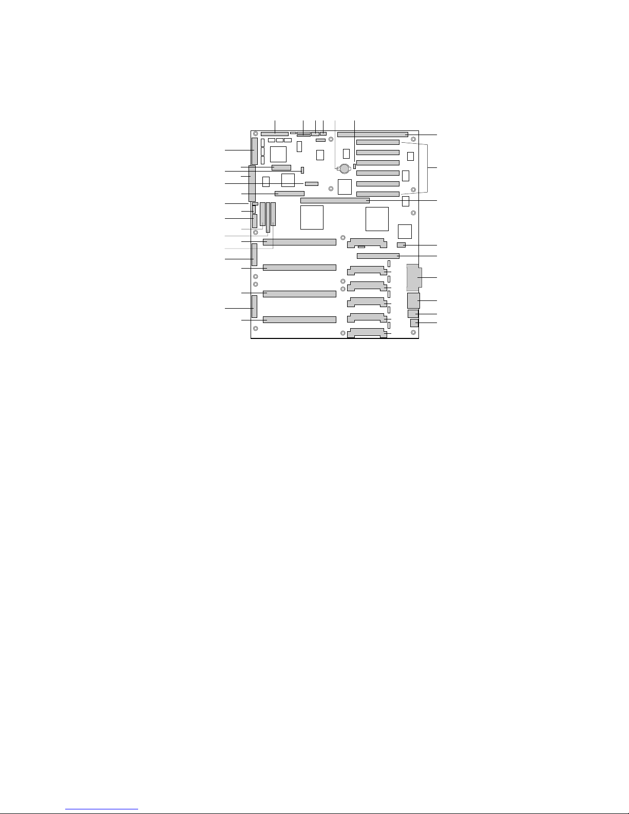
Baseboard Connector and Component Locations
C DA E FB
MM
LL
KK
JJ
II
HH
GG
FF
EE
DD
CC
BB
AA
Z
Y
X
W
V
Figure 6. Baseboard Connector and Component Locations
A. Wide SCSI B connector (J9J1) U. VRM connector for processor 1 (J4A1)
B. System jumpers (J6J1) V. Processor 1 Slot 2 connector (J9A1)
C. Hard drive input LED connector (J6J3) W. Main power connector, primary (J9B1)
D. System speaker connector (J6J2) X. Processor 2 Slot 2 connector (J9B2)
E. Lithium battery (B4H1) Y. Processor 3 Slot 2 connector (J9D1)
F. Wake on LAN† technology connector (J4H1) Z. Main power connector, secondary (J9D2)
G. ISA slot (J1J1) AA. Front panel connector (J8E1)
H. PCI slots B4 (closest to ISA), B3, B2, B1, A3,
and A2 (farthest from ISA)
I. Memory module connector (J3G1) CC. IDE connector (J9E2)
J. ICMB connector (J1E1) DD. Diskette drive connector (J9E3)
K. PCI slot A1 (J2D1) EE. Auxiliary power connector (J9E4)
L. Video and parallel port connectors (J1C1) FF. USB internal header (JC9F14)
M. Serial port connector (J1B2) GG. SMBus connector (J9F2)
N. Keyboard and mouse connectors (J1B1) HH. F16 expansion connector (J7G1)
O. USB external connector (J1A1) II. ITP connector (J6G1)
P. VRM connector for processor 4 (J4E1) JJ. Narrow SCSI connector (J9H1)
Q. VRM connector for processors 4 and 3 (J4C2) KK. External IPMB connector (J7H1)
R. VRM connector for processor 3 (J4C1) LL. SMM connector (J8H1)
S. VRM connector for processor 2 (J4B1) MM. Wide SCSI A connector (J9H2)
T. VRM connector for processors 2 and 1 (J4A2)
BB. Processor 4 Slot 2 connector (J9E1)
P
Q
R
S
T
U
G
H
I
J
K
L
M
N
O
OM08022
20
Page 21

Processor
Each Pentium II Xeon processor is packaged in a single edge contact (S.E.C.) cartridge. The
cartridge includes the processor core with an integrated 16 KB primary (L1) cache; the secondary
(L2) cache; a thermal plate; and a back cover.
™
The processor implements the MMX
™
the 8086, 80286, Intel386
, Intel486™, Pentium, and Pentium Pro processors. The processor's
numeric coprocessor significantly increases the speed of floating-point operations and complies
with ANSI/IEEE standard 754-1985.
Each S.E.C. cartridge connects to the baseboard through a 330-pin Slot 2 edge connector. The
cartridge is secured by a retention module attached to the baseboard. Depending on configuration,
your system has one to four processors.
The processor external interface is MP-ready and operates at 100 MHz. The processor contains a
local APIC unit for interrupt handling in multiprocessor (MP) and uniprocessor
(UP) environments.
The L2 cache is located on the substrate of the S.E.C. cartridge. The cache:
• Includes burst pipelined synchronous static RAM (BSRAM)
• Is offered in 512 KB, 1 MB, and 2 MB configurations
• Has ECC
• Operates at the full core clock rate
technology and maintains full backward compatibility with
21
Page 22
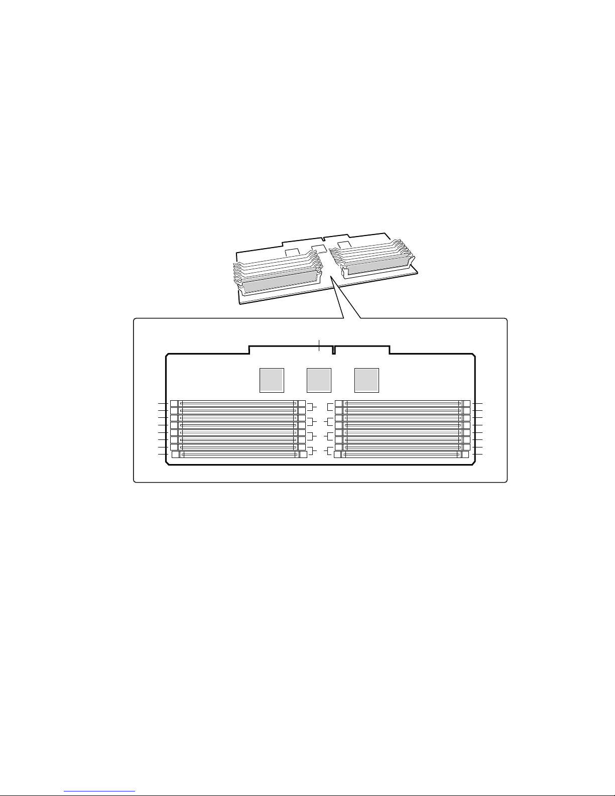
Memory
Main memory resides on an add-in board, called a memory module, designed specifically for the
SC450NX MP server. The memory module contains slots for 16 DIMMs, each of which must be
at least 32 MB, and is attached to the baseboard through a 242-pin connector. Memory amounts
from 128 MB to 4 GB of DIMM are supported, with a 64/72-bit four-way-interleaved pathway to
main memory, which is also located on the module. The 16 slots are divided into four banks of
four slots each, labeled A through D. These banks support 4:1 interleaving. The memory
controller supports EDO DRAMs. The ECC used for the memory module is capable of correcting
single-bit errors (SBEs) and detecting 100 percent of double-bit errors over one code word. Nibble
error detection is also provided.
E
J16
J15
J12
J11
D
C
J8
J7
J4
J3
B
A
J14
J13
J10
J9
J6
J5
J2
J1
OM08009
Figure 7. Memory Module DIMM Installation Sequence
A. Memory bank A (install first)
B. Memory bank B (install second)
C. Memory bank C (install third)
D. Memory bank D (install last)
E. Memory module connector
22
Page 23

System memory begins at address 0 and is continuous (flat addressing) up to the maximum amount
of DRAM installed (exception: system memory is noncontiguous in the ranges defined as memory
holes using configuration registers). The system supports both base (conventional) and extended
memory.
• Base memory is located at addresses 00000h to 9FFFFh (the first 1 MB).
• Extended memory begins at address 0100000h (1 MB) and extends to FFFFFFFFh (4 GB),
which is the limit of supported addressable memory. The top of physical memory is a
maximum of 4 GB (to FFFFFFFFh).
NOTE
✏
Addressable memory can be extended to 64 GB under certain
configurations, but this server is configured to support 4 GB.
Some OSs and application programs use base memory while others use both conventional and
extended memory. Examples:
• Base memory: MS-DOS
†
, OS/2†, Windows NT†, and UNIX
†
• Conventional and extended memory: OS/2, Windows NT, and UNIX
MS-DOS does not use extended memory; however, some MS-DOS utility programs like RAM
disks, disk caches, print spoolers, and windowing environments use extended memory for better
performance.
BIOS automatically detects, sizes, and initializes the memory array, depending on the type, size,
and speed of the installed DIMMs, and reports memory size and allocation to the system via
configuration registers.
In a 4 GB configuration, a small part of memory (typically 32 MB) is not remapped above 4 GB.
If your OS does not support more than 4 GB of physical memory, this small part of the memory is
effectively lost.
NOTE
✏
DIMM sizes and compatibility: use DIMMs that have been tested for
compatibility with the baseboard. Contact your sales representative or
dealer for a list of approved DIMMs. The table below lists some sample size
combinations.
Table 4. Sample DIMM Component Combinations
Bank C
Bank A (slots J1 - 4) Bank B (slots J5 - 8)
4x32 128 MB
4x32 4x32 256 MB
4x32 4x32 4x32 4x32 512 MB
4x64 4x64 4x64 4x64 1024 MB
4x128 4x128 4x128 4x128 2048 MB
(slots J9 - 12)
Bank D
(slots J13 - 16) Total Memory
23
Page 24

Peripherals
Super I/O Chip
The 87309 device supports two serial ports, one parallel port, diskette drive, and PS/2-compatible
keyboard and mouse. The system provides the connector interface for each port.
Serial Ports
Both serial ports are relocatable. By default, port A is physically the top connector, port B on the
bottom. Each serial port can be set to one of four different COMx ports, and each can be enabled
separately. When enabled, each port can be programmed to generate edge- or level-sensitive
interrupts. When disabled, serial port interrupts are available to add-in boards.
Parallel Port
The 25/15-pin connector stacks the parallel port over the VGA. The 87309 provides one
IEEE 1284-compatible 25-pin bidirectional EPP (supporting levels 1.7 and 1.9). BIOS
programming of the 87309 registers enables the parallel port and determines the port address and
interrupt. When disabled, the interrupt is available to add-in boards.
Add-in Board Slots
The baseboard has one ISA slot that is full-length if the wide SCSI-B slot is not used (and halflength if the wide SCSI-B slot is used); the ISA slot supports slave-only boards and is shared with
PCI-B slot 4. The ISA has three embedded devices: the Super I/O chip, Baseboard Management
Controller (BMC), and flash memory for system BIOS. ISA features:
• Bus speed up to 8.33 MHz
• 16-bit memory addressing
• Type A transfers at 5.33 MB/sec
• Type B transfers at 8 MB/sec
• 8- or 16-bit data transfers
• Plug and Play ready
The baseboard has two 32-bit PCI bus segments: PCI-A and PCI-B. These provide seven slots for
PCI add-in boards: three on PCI-A and four on PCI-B. PCI-B4 is shared with the ISA slot.
PCI-A1 supports half-length boards only. The other slots support full-length boards. PCI features:
• 33 MHz bus speed
• 32-bit memory addressing
• 5 V signaling environment
• Burst transfers of up to 133 MB/sec
• 8-, 16-, or 32-bit data transfers
• Plug and Play ready
• Parity enabled
24
Page 25

Video
The onboard, integrated Cirrus Logic CL-GD5480 64-bit VGA chip contains an SVGA controller
†
that is fully compatible with these video standards: CGA
VGA. The standard system configuration comes with 2 MB of 10 ns onboard video memory. The
video controller supports pixel resolutions of up to 1600 x 1200 and up to 16.7 M colors.
The SVGA controller supports analog VGA monitors (single and multiple frequency, interlaced
and noninterlaced) with a maximum vertical retrace noninterlaced frequency of 100 Hz.
You can not add video memory to this system. Depending on the environment, the controller
displays up to 16.7 M colors in some video resolutions. It also provides hardware-accelerated bit
block transfers (BITBLT) of data.
, EGA†, Hercules† Graphics, MDA†, and
SCSI Controller
The baseboard includes two SCSI controllers. A narrow SCSI controller (SYM53C810AE) is on
the PCI-A bus, and a dual-channel wide LVD/SE (Ultra2/Ultra) SCSI controller (SYM53C896) is
on the PCI-B bus. The narrow provides support for the legacy 8-bit SCSI devices in the 5.25-inch
drive bays. The wide drives one SCSI backplane and provides support for external expansion.
Internally, each wide channel is identical, capable of operations using either 8- or 16-bit SCSI
providing 10 MB/sec (Fast-10) or 20 MB/sec (Fast-20) throughput, or 20 MB/sec (Ultra),
40 MB/sec (Ultra-wide) or 80 MB/sec (40 Mhz) (Ultra-2).
The SYM53C810AE (narrow) contains a high-performance SCSI core capable of Fast 8-bit SCSI
transfers in single-ended mode. It provides programmable active negation, PCI zero wait-state
bursts of faster than 110 MB/sec at 33 MHz, and SCSI transfer rates from 5 to 10 MB/sec. The
narrow SCSI comes in a 100-pin rectangular plastic quad flat pack (PQFP) and provides an “AND
tree” structure for testing component connectivity.
The Sym53C896 (wide) contains a high-performance SCSI bus interface. It supports SE mode
with 8-bit (10 or 20 MB/sec) or 16-bit (20 or 40 MB/sec) transfers and LVD mode with
8-bit (40 MB/sec) or 16-bit (80 MB/sec) transfers in a 329-pin ball grid array (BGA) package.
Each controller has its own set of PCI configuration registers and SCSI I/O registers. As a
PCI 2.1 bus master, the SYM53C896 supports burst data transfers on PCI up to the maximum rate
of 132 MB/sec using on-chip buffers.
In the internal bay, the system supports up to six one-inch SCSI hard disk drives, plus, in the
5.25-inch removable media bays, three SCSI or IDE devices (the controller itself supports more
devices, but the 5.25-inch bay can contain a maximum of three devices). A wide SCSI cable
provides two connectors for Ultra SCSI devices (one of these connectors is for the optional SCSI
backplane, if your system has that). However, SCSI devices do not need to operate at the ultra
transfer rate. All drives on the bus must be Ultra-2 (LVD) to run at 80MB/sec (40Mhz). The 5,
10, and 20Mhz operations can coexist on the bus and each device will interact at its appropriate
speed.
No logic, termination, or resistor loads are required to connect devices to the SCSI controller other
than termination in the device at the end of the cable. The SCSI bus is terminated on the baseboard
with active terminators that can be disabled.
25
Page 26

IDE Controller
IDE is a 16-bit interface for intelligent disk drives with AT† disk controller electronics onboard.
The PCI/ISA/IDE Accelerator, called PIIX4E, is a multifunction device on the baseboard that acts
as a PCI-based Fast IDE controller. The device controls:
• PIO and IDE DMA/bus master operations
• Mode 4 timings
• Transfer rates up to 22 MB/sec
• Buffering for PCI/IDE burst transfers
• Master/slave IDE mode
• Up to two drives for one IDE channel
NOTE
✏
18-inch maximum length of IDE cable on each channel: you can connect
an IDE signal cable, up to a maximum of 18 inches, to the IDE connector on
the baseboard. The cable can support two devices, one at the end of the
cable and one six inches from the end.
Keyboard and Mouse
The PS/2-compatible keyboard and mouse connectors are mounted in a single-stacked housing
with the mouse connector over the keyboard. External to the system, they appear as two
connectors.
The user can plug in the keyboard and mouse to either connector before powering up the system.
BIOS detects these and configures the keyboard controller accordingly.
The keyboard controller is functionally compatible with the 8042A microcontroller. The system
can be locked automatically if no keyboard or mouse activity occurs for a predefined length of
time, if specified through the SSU. Once the inactivity (lockout) timer has expired, the keyboard
and mouse do not respond until the previously stored password is entered.
26
Page 27

Server Management
Server Management features are implemented using one microcontroller, the Baseboard
Management Controller (BMC).
Baseboard Management Controller (BMC)
The BMC and associated circuitry are powered from 5V_Standby, which remains active when
system power is switched off.
The primary function of the BMC is to autonomously monitor system platform management events
and log their occurrence in the nonvolatile System Event Log (SEL). These events include
overtemperature and overvoltage conditions, fan failure, or chassis intrusion. While monitoring,
the BMC maintains the nonvolatile sensor data record repository (SDRR), from which run-time
information can be retrieved. The BMC provides an ISA host interface to SDRR information, so
software running on the server can poll and retrieve the current status of the platform. A shared
register interface is defined for this purpose.
SEL contents can be retrieved after system failure for analysis by field service personnel using
®
system management tools like Intel
by 5V_Standby, SEL (and SDRR) information is also available via the interperipheral
management bus (IPMB). An emergency management board like the Intel LANDesk SMM board
can obtain the SEL and make it remotely accessible using a LAN or telephone line connection.
During monitoring, the BMC performs the following functions:
• Baseboard temperature and voltage monitoring
• Processor presence monitoring and FRB control
• Baseboard fan failure detection and indicator control
• SEL interface management
• Sensor Data Record Repository (SDRR) interface management
• SDR/SEL timestamp clock
• Baseboard Field Replaceable Unit (FRU) information interface
• System management watchdog timer
• Periodic SMI timer
• Front panel NMI handling
• Event receiver
• ISA host and IPMB interface management
• Secure mode control, front panel lock/unlock initiation, and video blank and diskette write
protect monitoring and control
• Sensor event initialization agent
• Wake on LAN via Magic Packet
• ACPI Support
• Emergency Management Port (EMP) support
LANDesk® Server Manager. Because the BMC is powered
†
support
27
Page 28

System Security
To help prevent unauthorized entry or use of the system, the system includes a three-position key
lock/switch to permit selected access to drive bays (position is communicated to BMC). The
system also includes server management software that monitors the chassis intrusion switch.
Mechanical Locks and Monitoring
The system includes a chassis intrusion switch. When the access cover is opened, the switch
transmits an alarm signal to the baseboard, where server management software processes the
signal. The system can be programmed to respond to an intrusion by powering down or by locking
the keyboard, for example.
Software Locks via the SSU or BIOS Setup
The SSU provides a number of security features to prevent unauthorized or accidental access to the
system. Once the security measures are enabled, access to the system is allowed only after the user
enters the correct password(s). For example, the SSU allows you to:
• Enable the keyboard lockout timer so the server requires a password to reactivate the keyboard
and mouse after a specified time-out period of 1 to 120 minutes
• Set and enable administrator and user passwords
• Set secure mode to prevent keyboard or mouse input and to prevent use of the front panel reset
and power switches
• Activate a hot-key combination to enter secure mode quickly
• Disable writing to the diskette drive when secure mode is set
Using Passwords
If you set and enable a user password but not an administrator password, enter the user password to
boot the system and run the SSU.
If you set and enable both a user and an administrator password:
• Enter either one to boot the server and enable the keyboard and mouse
• Enter the administrator password to access the SSU or BIOS Setup to change the system
configuration
Secure Mode
Configure and enable the secure boot mode by using the SSU. When secure mode is in effect, you:
• Can boot the system and the OS will run, but you must enter the user password to use the
keyboard or mouse
• Cannot turn off system power or reset the system from the front panel switches
Secure mode has no effect on functions enabled via the Server Manager Module or power control
via the real-time clock (RTC).
Taking the system out of secure mode does not change the state of system power. That is, if you
press and release the power switch while secure mode is in effect, the system will not power off
when secure mode is later removed. However, if the front panel power switch remains depressed
when secure mode is removed, the system will power off.
28
Page 29

Summary of Software Security Features
Table 5 lists the software security features and describes what protection each offers. In general,
to enable or set the features listed here, you must run the SSU and go to the Security Menu
(described in this manual on page 41). The table also refers to other SSU menus and to the Setup
utility. For greater detail, see Chapter 3, beginning on page 31.
Table 5. Software Security Features
Feature Description
Put the system into
secure boot mode
Disable writing to diskette In secure mode, the system will not boot from or write to a diskette unless a
Disable the power and
reset buttons
Set a time-out period so
that keyboard and mouse
input are not accepted
Also, screen can be
blanked and writes to
diskette can be inhibited
How to enter secure mode:
Setting and enabling passwords automatically puts the system into secure
mode.
If you set a hot-key combination (through the SSU or Setup), you can secure
the system simply by pressing the key combination. This means you do not
have to wait for the inactivity time-out period. See “Security Menu” on
page 41.
When the system is in secure mode:
The system can boot and run the OS, but mouse and keyboard input is not
accepted until the user password is entered.
At boot time, if a CD is detected in the CD-ROM drive or a diskette in drive A,
the system prompts for a password. When the password is entered, the
system boots from CD or diskette and disables the secure mode.
If you have not yet installed a CD-ROM drive, if there is no CD in the drive or
diskette in drive A, the system boots from drive C and automatically goes into
secure mode. All enabled secure mode features go into effect at boot time.
To leave secure mode:
Enter the correct password(s).
password is entered. To set these features, see “Secure Mode Boot” and
“Floppy Write Protect” in “Security Menu,” page 41.
If this protection feature is enabled by the SSU, the power and reset buttons
are disabled when in secure mode.
You can specify and enable an inactivity time-out period of from 1 to
120 minutes. If no keyboard or mouse action occurs for the specified period,
attempted keyboard and mouse input will not be accepted. To set this
feature, see “Secure Mode Timer” in “Security Menu,” page 41.
If video blanking is enabled, the monitor display will go blank until the correct
password(s) is entered. To set this feature, see “Video Blanking” in “Security
Menu,” page 41.
continued
29
Page 30

Table 5. Software Security Features
Feature Description
Control access to using
the SSU: set
administrator password
To control access to setting or changing the system configuration, set an
administrator password and enable it through Setup or the SSU.
If both the administrator and user passwords are enabled, either can be used
to boot the system or enable the keyboard and/or mouse, but only the
administrator password allows changes to Setup and the SSU.
Once set, passwords can be disabled by setting the password to a null string
or by changing the Clear Password jumper. See “Security Menu,” page 41;
or, to change a jumper, see “Baseboard Jumpers,” page 151.
(continued)
Control access to the
system other than SSU:
set user password
Boot without keyboard The system can boot with or without a keyboard. Before the system boots
Specify the boot
sequence
To control access to using the system, set a user password and enable
Password on Boot through Setup or the SSU.
Once set, passwords can be disabled by setting the password to a null string
or by changing the Clear Password jumper. See “Security Menu,” page 41;
or, to change a jumper, see “Baseboard Jumpers,” page 151.
during POST, BIOS automatically detects and tests the keyboard, if present,
and displays a message. No entry exists in the SSU for enabling or disabling
a keyboard. Do not plug in a keyboard while power is applied to the system.
The sequence you specify in the Boot Device Priority Submenu (see page 44)
of the SSU’s Boot Menu determines the boot order. If secure mode is
enabled (user password is set), you will be prompted for a password before
the system boots fully. If secure mode is enabled and the “Secure Mode
Boot” option is also enabled, the system boots fully but requires a password
before accepting any keyboard or mouse input.
30
Page 31

3 Configuration Software and Utilities
This chapter describes the Power-on Self Test (POST) and system configuration utilities. The
table below briefly describes the utilities.
Table 6. Configuration Utilities
Utility Description and brief procedure Page
BIOS Setup If the system does not have a diskette drive, or the drive is
disabled or misconfigured, use Setup to enable it.
Or, you can move the CMOS jumper on the system board from the
default setting (Protect CMOS memory) to the Clear setting; this
will allow most system configurations to boot. For the procedure to
do this, see “CMOS Clear Jumper” on page 152. Then run the
SSU to configure the system.
Server Setup Utility (SSU) Use for extended system configuration of onboard resources and
add-in boards, viewing the system event log (SEL), setting boot
device priority, or setting system security options.
The SSU can be run from either the configuration software CD or
from a set DOS-bootable diskettes. See the printed
to make a set of SSU diskettes.
Guide
Information entered via the SSU overrides information entered via
Setup.
Emergency Management
Port (EMP) Console
FRUSDR Load Utility Use to update the Field Replacement Unit (FRU), Sensor Data
BIOS Update Utility Use to update the BIOS or recover from a corrupted BIOS update. 74
Firmware Update Utility Use to update BMC flash ROM. 76
Symbios SCSI Utility Use to configure or view the settings of the SCSI host adapters
Use to access and monitor the server remotely. 57
Record (SDR), and Desktop Management Interface (DMI) flash
components.
and onboard SCSI devices in the system.
Quick Start
33
46
69
77
Hot Keys
Use the keyboard’s numeric pad to enter numbers and symbols.
Table 7. Hot Keys
To do this: Press these keys
Clear memory and reload the operating
systemthis is a system reset.
Secure your system immediately. <Ctrl+Alt>+hotkey (Set your hot-key combination with the
Enter BIOS Setup during POST BIOS. F2
Abort memory test during BIOS POST. ESC (press while BIOS is updating memory size on screen)
<Ctrl+Alt+Del>
SSU or Setup.)
31
Page 32

Power-on Self Test (POST)
Each time you turn on the system, POST starts running. POST checks the baseboard, processors,
memory, keyboard, and most installed peripheral devices. During the memory test, POST displays
the amount of memory it is able to access and test. The length of time needed to test memory
depends on the amount of memory installed. POST is stored in flash memory.
1. Turn on your video monitor and system. After a few seconds, POST begins to run.
2. After the memory test, these screen prompts and messages appear:
Keyboard Detected
Mouse Initialized
Press <F2> to enter Setup
3. If you do not press <F2> and do NOT have a device with an OS loaded, the above message
remains for a few seconds while the boot process continues, and the system beeps once. Then
this message appears:
Operating System not found
(To create software installation diskettes, see the printed Quick Start Guide.)
If you do not press <F2>, the boot process continues and this message appears:
Press <Ctrl><C> to enter SCSI Utility
4. Press <Ctrl+C> if SCSI devices are installed. When the utility opens, follow the displayed
instructions to configure the onboard SCSI host adapter settings and to run the SCSI utilities.
Also see “Using the Symbios SCSI Utility” on page 77. If you do not enter the SCSI utility,
the boot process continues.
5. Press <Esc> during POST to access a boot menu when POST finishes. From this menu, you
can choose the boot device or enter BIOS Setup.
After POST completes, the system beeps once.
What appears on the screen after this depends on if you have an OS loaded and if so, which one.
If the system halts before POST completes running, it emits a beep code indicating a critical
system error that requires immediate attention. If POST can display a message on the video
display screen, the speaker beeps twice as the message appears.
Note the screen display and write down the beep code you hear; this information is useful for your
service representative. For a listing of beep codes and error messages that POST can generate, see
Chapter 7, “Solving Problems,” beginning on page 123.
32
Page 33

Using BIOS Setup
This section describes the BIOS Setup options. Use Setup to change the system configuration
defaults. You can run Setup with or without an OS being present. Setup stores most of the
configuration values in battery-backed CMOS; the rest of the values are stored in flash memory.
The values take effect when you boot the system. POST uses these values to configure the
hardware; if the values and the actual hardware do not agree, POST generates an error message.
You must then run Setup to specify the correct configuration.
†
Run Setup: you can run Setup to modify any standard PC-AT
• Select diskette drive
• Select parallel port
• Select serial port
• Set time/date (to be stored in RTC)
• Configure IDE hard drive
• Specify boot device sequence
• Enable SCSI BIOS
Run SSU, not Setup: you must run the SSU instead of Setup to do the following:
• Enter or change information about a board
• Alter system resources (e.g., interrupts, memory addresses, I/O assignments) to user-selected
choices instead of choices selected by the BIOS resource manager
baseboard feature such as:
Record Your Setup Settings
If the default values ever need to be restored (after a CMOS clear, for example), you must run
Setup again. Referring to the worksheets could make your task easier.
If You Cannot Access Setup
If the diskette drive is misconfigured so that you cannot access it to run a utility from a diskette,
you might need to clear CMOS memory. You must open the system, change a jumper setting, use
Setup to check and set diskette drive options, and change the jumper back. For a step-by-step
procedure, see “CMOS Clear Jumper” on page 152.
Starting Setup
You can enter and start Setup under several conditions:
• When you turn on the system, after POST completes the memory test
• When you reboot the system by pressing <Ctrl+Alt+Del> while at the DOS operating system
prompt
• When you have moved the CMOS jumper on the baseboard to the “Clear CMOS” position
(enabled); for a step-by-step procedure, see “CMOS Clear Jumper” on page 152.
33
Page 34

In the three conditions listed above, after rebooting, you will see this prompt:
Press <F2> to enter SETUP
In a fourth condition, when CMOS/NVRAM has been corrupted, you will see other prompts but
not the <F2> prompt:
Warning: cmos checksum invalid
Warning: cmos time and date not set
In this condition, the BIOS will load default values for CMOS and attempt to boot.
Setup Menus
Setup has six major menus and several submenus:
1. Main Menu
• Primary IDE Master and Slave
• Keyboard Features
2. Advanced Menu
• PCI Configuration
PCI Device, Embedded SCSI
PCI Devices
• I/O Device Configuration
• Advanced Chipset Control
3. Security Menu
4. Server Menu
• System Management
• Console Redirection
5. Boot Menu
• Boot Device Priority
• Hard Drive
6. Exit Menu
To: Press:
Get general help <F1> or <Alt+H>
Move between menus
Go to the previous item
Go to the next Item
Change the value of an item + or Select an item or display a submenu <Enter>
Leave a submenu or exit Setup <Esc>
Reset to Setup defaults <F9>
Save and exit Setup <F10>
34
← →
↑
↓
Page 35

When you see this: What it means:
On screen, an option is shown but you cannot
select it or move to that field.
On screen, the phrase Press Enter appears next to
the option.
You cannot change or configure the option in that
menu screen. Either the option is autoconfigured or
autodetected, or you must use a different Setup
screen, or you must use the SSU.
Press <Enter> to display a submenu that is either a
separate full-screen menu or a pop-up menu with
one or more choices.
The rest of this section lists the features that display onscreen after you press <F2> to enter Setup.
Not all of the option choices are described, because (1) a few are not user-selectable but are
displayed for your information, and (2) many of the choices are relatively self-explanatory.
Main Menu
Table 8 lists the selections you can make on the Main Menu itself. Use the submenus for other
selections. Default values are in bold.
Table 8. Main Menu
Feature Choices Description
System Time HH:MM:SS Sets the system time.
System Date MM/DD/YYYY Sets the system date.
Legacy Diskette A: Disabled
360 KB
720 KB
1.44 MB
2.88 MB
Legacy Diskette B: Disabled
360 KB
720 KB
1.44 MB
2.88 MB
Hard Disk Pre-delay Disabled
3, 6, 9, 12, 15, 21,
or 30 seconds
Primary Master N/A Enters submenu.
Primary Slave N/A Enters submenu.
Keyboard Features N/A Enters submenu.
Language English (US)
Spanish
Italian
French
German
Japanese (Kanji)
Selects the diskette type.
Selects the diskette type.
Adds a delay before the first BIOS access of a hard disk
drive. Some hard disk drives hang if accessed before they
initialize themselves. This delay ensures the hard disk
drive has initialized after powerup, before being accessed.
Selects which language BIOS displays.
NOTE
✏
Serial redirection does
not work with Kanji.
35
Page 36

Primary Master and Slave Submenu
In the following table, the features other than “Type” appear only for Type Auto if a drive is
detected.
Table 9. Primary IDE Master and Slave Submenu
Feature Choices Description
Type
Cylinders 1 to 2048 Number of Cylinders on Drive.
Heads 1 to 16 Number of read/write heads on drive.
Sectors 1 to 64 Number of sectors per track.
Maximum Capacity
Multi-Sector Transfers
LBA Mode Control
32 Bit I/O
Transfer Mode
Auto
None
CD-ROM
IDE Removable
ATAPI Removable
User
N/A
Disabled
2, 4, 8, or 16
sectors
Disabled
Enabled
Disabled
Enabled
Standard
Fast PIO 1
Fast PIO 2
Fast PIO 3
Fast PIO 4
Auto allows the system to attempt autodetection of the
drive type.
None informs the system to ignore this drive.
CD-ROM allows the manual entry of fields described
below.
User allows the manual entry of all fields described below.
This field is changeable only for Type User.
This field is informational only for Type Auto.
This field is available only for Type User.
This field is informational only for Type Auto.
This field is available only for Type User.
This field is informational only for Type Auto.
Computed size of drive from cylinders, heads, and sectors
entered.
This field is available only for Type User.
This field is informational only for Type Auto.
Determines the number of sectors per block for multisector
transfers.
This field is informational only for Type Auto.
Enabling LBA causes logical block addressing to be used
in place of cylinders, heads, and sectors.
This field is informational only for Type Auto.
Enabling allows 32-bit IDE data transfers.
This field is informational only for Type Auto.
Selects the method for moving data to and from the drive.
This field is informational only for Type Auto.
Ultra DMA
36
Disabled
Enabled
For use with Ultra DMA drives.
This field is information only for Type Auto.
Page 37

Keyboard Features Submenu
Table 10. Keyboard Features Submenu
Feature Choices Description
Num Lock
Key Click
Keyboard auto-repeat rate
Keyboard auto-repeat delay 1/4 sec
Auto
On
Off
Disabled
Enabled
, 26.7, 21.8, 18.5, 13.3,
30
10, 6, or 2 per second
1/2 sec
3/4 sec
1 sec
Selects poweron state for Num Lock.
Enables or disables key click.
Selects key repeat rate.
Selects delay before key repeat.
Advanced Menu
You can make the following selections on the Advanced Menu itself. Use the submenus for the
three other selections that appear on the Advanced Menu.
Table 11. Advanced Menu
Feature Choices Description
Plug and Play OS
Reset Configuration Data
PCI Configuration N/A Enters submenu.
I/O Device Configuration N/A Enters submenu.
Use Multiprocessor
Specification
Large Disk Access Mode
Pause Before Boot
No
Yes
No
Yes
1.1
1.4
LBA
CHS
Enabled
Disabled
Select Yes if you are booting a Plug and Play-capable
OS.
Select Yes if you want to clear the system configuration
data during next boot. System automatically resets to No
in next boot.
Selects the version of multiprocessor specification to use.
Some operating systems require version 1.1 for
compatibility reasons.
Applies to IDE drives only; refers to the method used to
access the drive.
Most OSs use logical block addressing (LBA); some use
cylinder head sector (CHS). To verify correct method,
consult OS documentation.
Enables five-second pause before booting OS.
Advanced Chipset Control N/A Enters submenu.
37
Page 38

PCI Configuration Submenu
The PCI Configuration Menu contains selections that access other submenus.
PCI Device, Embedded SCSI Submenu
Table 12. PCI Device, Embedded SCSI Submenu
Feature Choices Description
Option ROM Scan
Enable Master
Latency Timer Default
PCI Devices Submenu
Table 13. PCI Devices Submenu
Feature Choices Description
Option ROM Scan
Enable Master
Latency Timer Default
Enabled
Disabled
Disabled
Enabled
0020h
0040h
0060h
0080h
00A0h
00C0h
00E0h
Enabled
Disabled
Enabled
Disabled
020h
040h
060h
080h
0A0h
0C0h
0E0h
Enables option ROM scan of the selected device.
Enables selected device as a PCI bus master.
Minimum guaranteed time, in units of PCI bus clocks, that a
device can be master on a PCI bus. Typically, option ROM
code overwrites the value set by the BIOS.
Enables option ROM scan of all devices other than the
onboard SCSI controllers.
Enables all devices, other than the onboard SCSI
controllers, as a PCI bus master.
Minimum guaranteed time, in units of PCI bus clocks, that a
device can be master on a PCI bus. Typically, option ROM
code overwrites the value set by the BIOS.
38
Page 39

I/O Device Configuration Submenu
Table 14. I/O Device Configuration Submenu
Feature Choices Description
Serial Port A Disabled
Enabled
Auto
OS Controlled
Base I/O Address
Interrupt
Serial Port B Disabled
Mode
Base I/O Address 3F8
Interrupt IRQ 4
Parallel Port Disabled
Mode
Base I/O Address
Interrupt IRQ 5
DMA channel
Floppy disk controller Disabled
Base I/O Address
3F8
2F8
3E8
2E8
IRQ 4
IRQ 3
Enabled
Auto
OS Controlled
Normal
†
IrDA
ASK-IR
2F8
3E8
2E8
IRQ 3
Enabled
Auto
OS Controlled
ECP
Output only
Bidirectional
EPP
378
278
IRQ 7
DMA 1
DMA 3
Enabled
Primary
Secondary
Auto forces BIOS to configure the port.
OS Controlled displays when OS controls the port.
Selects the base I/O address for COM port A.
Selects the IRQ for COM port A.
Auto forces BIOS to configure the port.
OS Controlled displays when OS controls the port.
Selects mode for COM port B.
Selects the base I/O address for COM port B.
Selects the interrupt for COM port B.
Auto forces BIOS to configure the port.
OS Controlled displays when OS controls the port.
Selects mode for parallel port.
Selects the base I/O address for parallel port.
Selects the interrupt for parallel port.
Selects the DMA channel for parallel port.
Enables onboard diskette controller.
Sets the base I/O address for the diskette controller.
PS/2 Mouse
Auto
Disabled
Enabled
Enables or disables onboard mouse. Disabling the mouse
frees up IRQ 12. If this feature is enabled, the OS can
determine whether to enable or disable the mouse.
39
Page 40

Advanced Chipset Control Submenu
Table 15. Advanced Chipset Control Submenu
Feature Option Description
Address Bit Permuting
Disabled
Enabled
To be enabled, there must be a power of 2 number of
rows, all rows must be the same size, and all
populated rows must be adjacent and start at row 0.
Two-way or four-way permuting is set automatically
based on memory configuration.
Base RAM Step
Extended RAM Step
L2 Cache
ISA Expansion Aliasing
Memory Scrubbing
Restreaming Buffer
Read Prefetch for PXB0A N/A Information field only. Configures the number of
1 MB
1 KB
Every location
1 MB
1 KB
Every location
Enabled
Disabled
Enabled
Disabled
Disabled
Enabled
Enabled
Disabled
Tests base memory once per MB, once per KB, or
every location.
Tests extended memory once per MB, once per KB, or
every location.
When enabled, the secondary cache is sized and
enabled. For Core Clock Frequency-to-System Bus
ratios equal to two, BIOS automatically disables the
L2 cache.
When enabled, every I/O access with an address in
the range x100-x3FFh, x500-x7FFh, x900-xBFF, and
xD00-xFFFh is internally aliased to the range 010003FFh before any other address range checking is
performed.
When enabled, BIOS automatically detects and
corrects SBEs.
When enabled, the data returned and buffered for a
Delayed Inbound Read can be reaccessed following a
disconnect.
Dwords that are prefetched on Memory Read Multiple
commands.
Read Prefetch for PBX0B N/A Information field only. Configures the number of
40
Dwords that are prefetched on Memory Read Multiple
commands.
Page 41

Security Menu
You can make the following selections on the Security Menu. Enabling the Supervisor Password
field requires a password for entering Setup. The passwords are not case sensitive.
Table 16. Security Menu
Feature Choices Description
Administrator Password is Clear
Set
User Password is Clear
Set
Set Administrative Password Press Enter When the <Enter> key is pressed, the user is prompted for a
Set User Password Press Enter When the <Enter> key is pressed, the user is prompted for a
Password on Boot Disabled
Enabled
Fixed Disk Boot Sector Normal
Write
Protect
System Backup Reminder Disabled
Daily
Weekly
Monthly
Virus Check Reminder Disabled
Daily
Weekly
Monthly
Secure Mode Timer Disabled
1, 2, 5, 10,
or 20 min
1 or 2 hr
Secure Mode Hot Key
(Ctrl-Alt- )
Secure Mode Boot Disabled
Video Blanking Disabled
Floppy Write Protect Disabled
[ ]
[A, B, ..., Z]
[0-9]
Enabled
Enabled
Enabled
Status only; user cannot modify. Once set, this can be
disabled by setting it to a null string or by clearing password
jumper on baseboard (see “Baseboard Jumpers,”
page 151).
Status only; user cannot modify. Once set, this can be
disabled by setting it to a null string or by clearing password
jumper on baseboard (see “Baseboard Jumpers,” page 151).
password; press ESC key to abort. Once set, this can be
disabled by setting it to a null string or by clearing password
jumper on baseboard (see “Baseboard Jumpers,” page 151).
password; press ESC key to abort. Once set, this can be
disabled by setting it to a null string or by clearing password
jumper on baseboard (see “Baseboard Jumpers,” page 151).
If enabled and the user password is set, the system prompts
the user for a password before the system boots.
Write-protects boot sector on hard disk to protect against
viruses.
Displays system-backup reminder message at boot.
Displays virus-check reminder message at boot.
Period of keyboard or PS/2 mouse inactivity specified for
secure mode to activate. A password is required for secure
mode to function. Cannot be enabled unless at least one
password is enabled.
Key assigned to invoke the secure mode feature. Cannot
be enabled unless at least one password is enabled. Can
be disabled by entering a new key followed by a backspace
or by entering <Delete>.
System boots in secure mode. The user must enter a
password to unlock the system. Cannot be enabled unless
at least one password is enabled.
Blank video when secure mode is activated. The user must
enter a password to unlock the system. Cannot be enabled
unless at least one password is enabled.
When secure mode is activated, the diskette drive is write
protected. The user must enter a password to reenable
diskette writes. Cannot be enabled unless at least one
password is enabled.
41
Page 42

Server Menu
Table 17. Server Menu
Feature Choices Description
System Management N/A Enters submenu.
Console Redirection N/A Enters submenu.
Processor Retest No
Yes
System Management Submenu
Table 18. System Management Submenu
Feature Choices Description
Server Management Mode Disabled
Enabled
System Event Logging Disabled
Enabled
Clear Event Log Disabled
Enabled
Assert NMI on AERR Disabled
Enabled
Assert NMI on BERR Disabled
Enabled
Assert NMI on PERR Disabled
Enabled
Assert NMI on SERR Disabled
Enabled
Enabled Host Bus Error Disabled
Enabled
Instructs BIOS to clear historical processor status and to
retest all processors on next boot.
Enabled loads Server Management Interrupt handler,
which handles system errors.
Enabled forces BIOS and BMC to log system events.
Enabled clears the system event log.
Enabled generates a nonmaskable interrupt (NMI) on an
address parity error (AERR).
Enabled generates an NMI on a bus error (BERR).
Enabled generates an NMI on a parity error (PERR). To
activate this feature, the system error (SERR) option
must be enabled.
Enabled generates an NMI on SERR.
Enables host single-bit errors (SBEs) and multiple-bit
errors (MBEs).
42
Page 43

Console Redirection Submenu
Table 19. Console Redirection Submenu
Feature Choices Description
COM Port Address
IRQ # None, 3, or 4 When console redirection is enabled, this displays the IRQ
Baud Rate 9600
Flow Control No flow control
Disabled
3F8
2F8
3E8
19.2k
38.4k
115.2k
CTS/RTS
XON/XOFF
CTS/RTS + CD
When enabled, console redirection uses the I/O port specified.
When disabled, console redirection is completely disabled.
assigned per the address chosen in the COM Port Address
field.
When console redirection is enabled, use the baud rate
specified.
When the Emergency Management Port (EMP) shares the COM
port as console redirection, the baud rate must be set to 19.2k
to match EMP baud rate, unless the autobaud feature is used.
None disallows flow control.
CTS/RTS is hardware flow control.
XON/XOFF is software flow control.
CTS/RTS +CD is hardware plus carrier-detect flow control.
Boot Menu
You can make the following selections on the Boot Menu itself.
Table 20. Boot Menu
Feature Choices Description
Floppy Check
Multi-boot Support
Boot Device Priority N/A Enters submenu.
Hard Drive N/A Enters submenu.
Removable Devices N/A Enters submenu.
Maximum Number of I2O Drives
Message Timeout Multiplier
Disabled
Enabled
Disabled
Enabled
1
4
, 2, 8, 10,
1
50, 100, 1000
If Enabled, system verifies diskette type on boot.
Disabled results in a faster boot.
Enable this option only if the total number of hard
drives is less than eight.
Selects the maximum number of I2O drives assigned
a DOS drive letter.
All timeout values are multiplied by this number.
43
Page 44

Boot Device Priority Submenu
Use the up- or down-arrow keys to select a device. Press the <+> or <-> keys to move the device
higher or lower in the boot priority list.
Table 21. Boot Device Priority Submenu
Boot Priority Device Description
1. Diskette Drive Attempts to boot from drive A.
2. Removable Devices Attempts to boot from a removable media device.
3. Hard Drive Attempts to boot from a hard drive device.
4. ATAPI CD-ROM Drive Attempts to boot from an ATAPI CD-ROM drive.
Hard Drive Submenu
For options on this menu, use the up or down arrow keys to select a device. Press the <+> or <->
keys to move the device higher or lower in the boot priority list.
Table 22. Hard Drive Submenu
Option Description
1. Drive #1 (or actual drive string) N/A
2. Other bootable cards
(additional entries for each drive that
has a PnP header)
Covers all the boot devices that are not reported to the system
BIOS through the BIOS boot specification mechanism.
44
Page 45

Exit Menu
You can make the following selections on the Exit Menu. Select an option using the up or down
arrow keys. Press <Enter> to run the option. Pressing <Esc> does not exit this menu. You must
select one of the items from the menu or menu bar to exit.
Table 23. Exit Menu
Choices Description
Exit Saving Changes Exits after writing all modified Setup item values to NVRAM.
Exit Discarding Changes Exits leaving NVRAM unmodified and continues POST. User is
prompted if any of the Setup fields were modified.
Load Setup Defaults Loads default values for all Setup items.
Load Custom Defaults Loads settings from custom defaults.
Save Custom Defaults Saves present Setup values to custom defaults. These settings
override the standard BIOS defaults; BIOS loads these values when
CMOS is corrupted or when the Clear CMOS jumper is in the clear
position.
CAUTION
Verify that custom defaults are
saved before saving. Failure to
do so can result in system
malfunction.
Discard Changes Reads previous values of all Setup items from NVRAM.
Save Changes Writes all Setup item values to NVRAM.
45
Page 46

Using the System Setup Utility (SSU)
The SSU is on the configuration software CD shipped with the server. The SSU provides a
graphical user interface (GUI) over an extensible framework for server configuration. The
SSU framework supports the following functions and capabilities:
• Assigns resources to baseboard devices and add-in boards before loading the OS
• Lets you specify boot device order and system security options
• Permits viewing and clearing of the system event log (SEL)
• Permits viewing of the system FRU and SDRs
• Allows troubleshooting of the server when the OS is not operational
• Provides a system-level view of the server’s I/O devices
When to Run the SSU
The SSU is a DOS-based utility that supports extended system configuration operations for
onboard resources and add-in boards. Use the SSU when you need to:
• Add and remove boards affecting the assignment of resources (ports, memory, IRQs, DMA)
• Modify the server’s boot device order or security settings
• Change the server configuration settings
• Save the server configuration
• View or clear the SEL
• View FRU information
• View the SDR table
If you install or remove an ISA add-in board, you must run the SSU to reconfigure the server.
Running the SSU is optional for PCI and Plug and Play ISA add-in boards.
The SSU is PCI-aware and complies with the ISA Plug and Play specifications; it works with any
compliant configuration (.CFG) files supplied by the peripheral device manufacturer.
The baseboard comes with a .CFG file describing the characteristics of the board and the system
resources it requires. The configuration registers on PCI and ISA Plug and Play add-in boards
contain the same type of information in a .CFG file. Some ISA boards also come with a .CFG file.
The SSU uses the information provided by .CFG files, configuration registers, flash memory, and
the information that you enter, to specify a system configuration. The SSU then writes the
configuration information to flash memory.
The SSU stores configuration values in flash memory. These values take effect when you boot the
server. POST checks the values against the actual hardware configuration; if the values do not
agree, POST generates an error message. You must then run the SSU to specify the correct
configuration before the server boots.
The SSU always includes a checksum with the configuration data so the BIOS can detect any
potential data corruption before the actual hardware configuration takes place.
46
Page 47

What You Need to Do
You can run the SSU directly from the configuration software CD after you have installed a
CD-ROM drive, or from a set of DOS diskettes.
If you choose to run the SSU from DOS diskettes, you must copy the SSU from the CD to the
diskettes and follow the instructions in the included README.TXT file to prepare the diskettes.
If your diskette drive is disabled or improperly configured, you must use the flash-resident Setup
utility to enable it so you can use the SSU. If necessary, you can disable the drive after exiting the
SSU. Information entered using the SSU overrides any entered using Setup.
Running the SSU
Running the SSU Locally
Running the ssu.bat file provided on the SSU media starts the SSU. If the server boots directly
from the SSU media, the ssu.bat file runs automatically. If the server boots from different media,
the SSU can be started manually or by another application. When the utility starts in the local
execution mode (the default mode), the SSU accepts input from the keyboard and/or mouse. The
SSU presents a VGA-based GUI on the primary monitor.
The SSU runs from writable, nonwritable, removable, and nonremovable media. If the SSU is run
from nonwritable media, user preference settings (like screen colors) cannot be saved.
The SSU supports the ROM-DOS V6.22 OS. It can run on other ROM-DOS compatible OSs, but
they are not supported. The SSU will not operate from a “DOS window” running under an OS like
Windows.
Running the SSU Remotely
To run the SSU remotely, you must invoke the SSU.BAT file with the /t switch and redirect the
text-mode output via BIOS console redirect.
Starting the SSU
The SSU is a collection of task-oriented modules plugged into a common framework called the
Application Framework (AF). The AF provides a launching point for individual tasks and a
location for setting customization information.
1. Turn on your video monitor and your system.
2. Start the SSU through one of two ways:
• After creating a set of SSU diskettes from the CD: Insert the first SSU diskette in drive
A. Press the reset button or <Ctrl+Alt+Del> to reboot your server from the diskette.
• Directly from the Server Configuration Software CD: Insert the configuration software
CD into your CD-ROM drive. Press the reset button or <Ctrl-Alt-Del> to reboot. When
prompted to do so, press <F2> to enter BIOS Setup. From the Boot Menu, select the
Boot Device Priority option. Select CD-ROM as your primary boot device. Save those
settings and exit BIOS Setup. The server will boot from the CD-ROM and display a menu
of options. Follow the instructions in the menu to start the SSU.
47
Page 48

3. When the SSU title appears on the screen, press <Enter> to continue.
4. The mouse driver loads if it is available; press <Enter> to continue.
This message appears:
Please wait while the Application Framework loads....
When the main window of the SSU appears, you can customize the UI before continuing. See
“Customizing the SSU” on page 49.
48
Figure 8. SSU Main Window
Page 49

Customizing the SSU
You can customize the UI according to your preferences. The AF sets these preferences and saves
them in the AF.INI file so that they take effect the next time you start the SSU. Use these four
user-customizable settings:
• Color—lets you change the default colors associated with different items on the screen to
predefined color combinations. The changes are instantaneous.
• Mode—lets you set the desired expertise level.
Novice
Intermediate
Expert
The expertise level determines which tasks are visible in the Available Tasks section and what
actions each task performs. For a new mode setting to take effect, you must exit the SSU and
restart it. In the current implementation, there is no distinction between these three different
modes.
• Language—lets you change the text displayed in the SSU to the appropriate language. For a
new language setting to take effect, you must exit the SSU and restart it.
• Other—lets you change other miscellaneous options in the SSU. The changes are immediate.
To change the interface default values:
• Use the mouse to click on the proper button in the Preferences section of the SSU Main
window.
OR
• Use the tab and arrow keys to highlight the desired button, and press the spacebar or <Enter>.
OR
• Access the menu bar with the mouse or hot keys (Alt + underlined letter).
NOTE
✏
If you run the SSU from nonwritable media (like a CD-ROM), these
preferences will be lost when you exit the SSU.
Launching a Task
It is possible to have many tasks open at the same time, although some tasks might require
complete control to avoid possible conflicts. The tasks achieve complete control by commanding
the center of operation until you close the task window.
To launch a task:
• In the SSU Main window, double-click on the task name under Available Tasks to display the
main window for that task.
OR
• Highlight the task name, and click <OK>.
OR
• Use the tab and arrow keys to highlight the desired button, and press the spacebar or <Enter>.
49
Page 50

Resource Configuration Add-in (RCA) Window
The RCA provides three major functions:
• Creates representations of devices that cannot be discovered by the system (ISA boards)
• Modifies the contents of the system by adding and removing devices
• Modifies the resources used by devices
You can use the RCA window to define or add an ISA board by clicking on the appropriate button.
To remove an ISA board, highlight the board in the Devices section of the screen before clicking
on the button. You can add only as many ISA boards as ISA slots available.
1. From the SSU main window, launch the RCA by selecting the “Resources” task under the
RCA heading in the task box.
2. When the RCA window appears, it displays messages similar to the following:
Baseboard: System Board
PCI Card: Bus 00 dev 00 -– Host Processor Bridge
PCI Card: Bus 00 dev 0D –- Multifunction Controller
PCI Card: Bus 00 dev 0F –- Ethernet Controller
PCI Card: Bus 00 dev 12 –- Multifunction Controller
PCI Card: Bus 00 dev 14 –- VGA Controller
3. To configure a device, click on it or select its name in the Devices section of the RCA window
and press the spacebar or <Enter>.
4. You can close the RCA window and return to the AF by clicking on the Close button. Any
changes made will be kept in memory for use by the RCA when it is rerun.
5. Save all changes by clicking <Save>. Saving writes your current configuration to nonvolatile
storage where it will be available to the system after every reboot.
6. Closing the window by clicking on the system menu (the dash in the upper-left corner)
discards all changes.
Defining an ISA Board
An ISA board usually comes with a vendor-created .CFG file that specifies the resources the card
requires to function properly. If the .CFG file is unavailable, you must manually create it or define
the board through the SSU. Defining an ISA board consists of specifying the name of the board
and the resources it consumes. This allows the RCA to consider the ISA board resource
requirements when the RCA tries to resolve conflicts. BIOS also uses this information to
configure hardware when the system is booted.
1. To add or remove ISA board resources, click on the appropriate resource buttons, select the
desired value, and click <Add> or <Remove>.
2. After you complete the necessary information, click <Save>.
3. To edit a board, click <Load> to retrieve the board information. After making changes, click
<Save>.
4. To create a board, click <New>.
5. To remove a current definition of a board, click <Delete>.
50
Page 51

Adding and Removing ISA Boards
Adding and removing boards through the RCA provides a way for the RCA to run its conflict
detection algorithms on the resources requested by the boards. This alerts you to any possible
problems with that particular board in the current configuration.
To add an ISA board:
1. Click <Add ISA Board> in the RCA window.
2. Specify the directory for the .CFG file.
3. Select the file and click <OK>.
To remove an ISA board:
1. Select a valid ISA board in the Devices section of the RCA window.
2. Click <Remove ISA Board>.
Modifying Resources
Modifying the resources of a device may be necessary to accommodate certain OSs, applications,
and drivers. It may also be necessary to modify resources to resolve a conflict.
To modify the resources associated with a device:
1. Highlight the device in the Devices section of the RCA window.
2. Press the spacebar or <Enter>, or double-click on the entry.
This displays the functions of the selected device along with possible choices and the resources
associated with those choices.
To make a modification:
1. Highlight the function in the Configuration window.
2. Press the spacebar or <Enter>, or double-click on the entry (this updates the choice and
resource lists).
3. Press the tab key to get to the choice list, and press <Enter>.
4. Use the arrow keys to select a proper choice, and press <Enter> again.
5. If the choice allows multiple possible values for a particular resource, use the hot key to
select a resource and press the spacebar or double-click on the resource.
6. Select the desired resource, and click <OK>.
System Resource Usage
Click <Resource Use> in the Configuration window to display the System Resource Usage
window, which shows the resources each device consumes. This information is useful if a conflict
occurs. Devices can be organized according to the resources you want to examine using the
options in the Resource section of the screen. The resource information can also be written to a
plain text file through this window.
Multiboot Options Add-in
In this window, you can change the boot priority of a device.
1. Select a device
2. Press <+> to move the device up in the list (higher priority). Press <-> to move it down.
51
Page 52

Security Add-in
In this window, you can set the User and Administrator passwords and security options.
To Set the User Password
1. Click <User Password>.
2. Enter the password in the first field.
3. Confirm the password by entering it again in the second field.
To Change or Clear the User Password
1. Click <User Password>.
2. Enter the old password in the first field.
3. Enter the new password in the second field (or leave blank to clear).
4. Confirm the password by entering it again in the second field (or leave blank to clear).
To Set the Administrator Password
1. Click <Administrator Password>.
2. Enter the password in the first field.
3. Confirm the password by entering it again in the second field.
To Change or Clear the Administrator Password
1. Click <Administrator Password>.
2. Enter the old password in the first field.
3. Enter the new password in the second field (or leave blank to clear).
4. Confirm the password by entering it again in the second field (or leave blank to clear).
Security Options
In this window, you can set the other security options:
• Hot Key—sets a key sequence that puts the server into secure mode when the key is pressed.
• Lock-Out Timer—sets an interval that puts the server into secure mode when no activity
occurs during the interval.
• Secure Boot Mode—forces the server to boot directly into secure mode.
• Video Blanking—turns off the video when the server is in secure mode.
• Floppy Write—controls access to the diskette drive when the server is in secure mode.
• Reset/Power Switch Locking—controls the power and reset buttons when the server is in
secure mode.
System Event Log (SEL) Viewer Add-in
Clicking on the SEL add-in task brings up the SEL viewer add-in, which allows users to:
• Examine SEL records via the BMC in hex or verbose mode
• Examine SEL records by sensor or event type in hex or verbose mode
• Examine SEL records from a previously stored binary file in hex or verbose mode
• Save SEL records to a file in either text or binary form
• Clear SEL entries from the non-volatile storage area
52
Page 53

The SEL viewer’s main window provides access to features of the add-in. Each option included on
the main menu supports an accelerator key. Accelerator keys are indicated by an underlined letter
in the text listing the option. The main window includes support to display the following
information for each SEL entry: record identifier, event type, time stamp information, generator
identifier, emv revision, sensor type, sensor number, and event description.
Figure 9 shows the SEL viewer main window. Table 24 lists the window’s menus and options.
Table 24. SEL Viewer Menus
Menu Options
File
View
Settings
Help
Open SEL
Save SEL
Clear SEL
Exit
SEL Info
All Events
By Sensor
By Event
Display Hex/Verbose
Output Text/Binary
Save) in binary format or verbose format
About
: Views data from previously saved SEL file
: Saves the currently loaded SEL data to a file
: Clears the SEL data from the BMC
: Quits the SEL Viewer
: Displays information about the SEL (display only)
: Displays the current SEL data from the BMC
: Displays a pop-up menu allowing you to view the data from a certain sensor type
: Displays a pop-up menu allowing you to view the data from a certain event type
: Displays the SEL Viewer version information
Figure 9. SEL Viewer Add-in Main Window
: Toggles between Hex/interpreted mode of displaying the SEL records
: Determines whether SEL data will be saved to the file (and under File -
53
Page 54

Sensor Data Record (SDR) Manager Add-In
In this window, you can:
• Examine all SDR records through the BMC (in either Hex or Verbose mode)
• Examine SDR records by Record type (in either Hex or Verbose mode)
• Examine SDR records from a previously stored binary file (in either Hex or Verbose mode)
• Save the SDR records to a file (in either text or binary form)
The SDR Manager can display SDR records in either raw form (hexadecimal) or in an interpreted,
easy-to-understand textual form (verbose).
The SDR Manager’s main window provides access to features of the add-in through menus. Each
option included on the main menu supports an accelerator key. Accelerator keys are indicated by
an underlined letter in the text listing the option.
Figure 10 shows the SDR Manager main window. Table 25 lists the window’s menus and options.
54
Figure 10. SDR Manager Main Window
Page 55

Table 25. SDR Manager Menus
Menu Options
File
View
Settings
Help
Open FRU
Save SDR
Exit
SDR Info
All Records
By Record
Display HEX
Display Verbose
Output Text
Output Binary
About
: Opens FRU data from a previously saved file
: Saves SDR data to a file in binary raw or verbose text format
: Quits the SDR Manager
: Displays SDR information as returned by the GetSDRInfo interface of the BMC
: Displays all records in the SDR repository
: Displays all records in the SDR repository, sorted by record type
: Displays SDR records in Hex format
: Displays SDR records in verbose format
: Saves SDR data in verbose format
: Saves SDR data in binary format
: Displays SDR Manager version information
Field Replaceable Unit (FRU) Manager Add-In
In this window you can:
• Examine all FRU Inventory areas on the server (in either Hex or Verbose mode)
• Examine individual FRU Inventory areas (in either Hex or Verbose mode)
• Examine FRU Inventory areas from a previously stored binary file (in either Hex or Verbose
mode)
• Save the FRU Inventory areas to a file (in either text or binary form)
The FRU Manager can display the FRU Inventory areas in either raw form (hexadecimal) or in an
interpreted, easy-to-understand textual form (verbose). The FRU manager’s main window
provides access to features of the add-in through menus. Each option included on the main menu
supports an accelerator key. Accelerator keys are indicated by an underlined letter in the text
listing the option.
55
Page 56

Figure 11 shows the FRU Manager main window. Table 26 lists the window’s menus and options.
Figure 11. FRU Manager Main Window
56
Page 57

Table 26. FRU Manager Menus
Menu Options
File
View
Settings
Help
Open FRU
Save FRU
Exit
FRU Info
All FRU Areas
By Device Type
Display HEX
Display Verbose
Output Text
Output Binary
About
: Opens FRU data from a previously saved file
: Saves FRU data to a file in binary raw or verbose text format
: Quits the FRU Manager
: Displays FRU information of the selected device
: Displays FRU areas of all devices
: Displays FRU areas sorted by device type
: Displays FRU areas in Hex format
: Displays FRU areas in verbose format
: Saves FRU data in verbose format
: Saves FRU data in binary format
: Displays FRU Manager version information
Exiting the SSU
Exiting the SSU causes all windows to close.
1. Exit the SSU by opening the menu bar item F
2. Click <Exit>
or
Highlight Exit, and press <Enter>.
ile in the SSU Main window.
Emergency Management Port (EMP) Console
The EMP console provides an interface, called the console manager, to the EMP. This interface
allows remote server management via a modem or direct connection.
The following server control operations are available with the console manager:
• Connecting to remote servers
• Powering the server on or off
• Resetting the server
• Switching the server console between EMP active and BIOS re-direct modes
The console manager uses three management plug-ins to monitor the server: the SEL, SDR, and
FRU viewers.
The console manager also has a support plug-in phonebook, which you can use to create and
maintain a list of servers and their phone numbers. You can launch the Connect dialog directly
from the Phonebook dialog to connect to a selected server.
57
Page 58

How the EMP Console Works
The EMP shares the COM2 port with the system. When the EMP has control of the port, the port
operates in command state. When the system has control of it, the port operates in redirect state.
When connecting to a server, the EMP console checks to determine the current COM2 port state.
• Command state—the default COM2 state. In this state, the EMP console communicates with
the server's firmware, allowing the client to remotely reset or power the server up or down.
The client can also view the server's SEL, FRU information, or SDR table.
• Redirect state—the EMP console serves as a PC ANSI terminal window for BIOS console
redirection. Commands typed in this terminal window are transmitted through BIOS to the
server's console, and text displayed on the server console is displayed on the EMP console's
terminal window. With the EMP in this state, you can remotely view boot messages, access
BIOS setup, and run DOS text mode applications through the EMP console's terminal window.
58
Figure 12. EMP Console in Command State
Page 59

Figure 13. EMP Console in Redirect State
Figure 13 shows the EMP console window in redirect state with the terminal window. The text
that appears on the server monitor displays in the redirect window.
Availability of the various EMP console features is determined by two things: the EMP access
mode selected during configuration in the System Management Submenu of the BIOS Server
Menu, and whether the server's COM2 port is configured for console redirect in BIOS. The three
EMP access modes are disabled, pre-boot, and always active.
Table 27. EMP Console Access Modes (Server Configured for Console Redirect)
Mode Server is powered off During POST After OS boots
Disabled Redirect window appears, but is blank Redirect window Redirect window
Pre-boot EMP commands available Redirect window* Redirect window
Always Active EMP commands available Redirect window* EMP commands available
* You can modify the operation mode by selections in the POST reset and POST power-up dialogs. These are server
control dialogs available with the EMP Console.
Table 28. EMP Console Access Modes (Server NOT configured for console redirect)
Mode Server is powered off During POST After OS boots
Disabled Redirect window appears,
but is blank
Pre-boot EMP commands available EMP commands available Redirect window appears,
Always Active EMP commands available EMP commands available EMP commands available
Redirect window appears,
but is blank
Redirect window appears,
but is blank
but is blank
59
Page 60

EMP Console Requirements
This section outlines the requirements and configurations necessary for using the EMP console.
Operating Systems:
†
• Windows
16 MB of RAM, 32 MB recommended
20 MB disk space
• Windows NT
Windows NT 4.0 or later
24 MB of RAM, 32 MB recommended
20 MB disk space
Client Configuration: The EMP console will support all COM ports on the client system, along
with any Windows NT/95 compatible modem.
Server Configuration: The EMP console requires that the server's COM2 port be connected to an
external modem or directly connected to a serial cable.
Direct Connect Configuration: A null modem serial cable is needed. Connect one end of the
cable into the COM2 port of the server and the other into a port on the client machine.
Modem Configuration: On the client, the EMP console uses the Windows application program
interface (API) to determine if a modem is connected and available. The EMP Console does not
configure the modem; it should be preconfigured through Windows.
95
For modem support, the server must use a Hayes-compatible 14400 bps modem. The modem must
be on the NT hardware compatibility list provided by Microsoft. The server modem must be set in
autoanswer mode for the EMP console to be able to connect to it.
Setting Up the Server for the EMP
To use the EMP, you must configure BIOS with specific settings. Enter these settings in two
submenus of the BIOS Server Menu: the System Management Submenu and the Console Redirect
Submenu. The section above on BIOS settings shows all available options. The sections below
focus on the settings that must be configured to use the EMP.
60
Page 61

System Management Submenu
All EMP-related settings occur from the System Management Submenu of the server Main Menu.
Change only the items below; all other default settings should remain the same.
EMP Password: Any time you attempt to initiate a connection, a prompt for the user password
appears. If you never set up the EMP password, anyone can access the EMP by clicking <OK>
through the password prompt.
In the EMP password area of the System Management Submenu, type in a password of up to eight
alphanumeric characters. If the system beeps, the password was not accepted; you must enter a
different password.
EMP Access Modes: Choose either disabled, pre-boot, or always active, depending on the type of
EMP access needed. Tables 27 (page 59) and 28 (page 59) list what is available with a given
setting.
EMP Restricted Mode Access: Set restricted mode to either enabled or disabled. In enabled
mode, the EMP console's server control options, Power On/Off and Reset, are NOT available. In
disabled mode, these options ARE available.
EMP Direct Connect/Modem Mode: Select Direct Connect if a null modem serial cable directly
connects the server's COM2 port to the EMP console client machine. If they are connected via a
modem, select Modem Mode.
Console Redirection Submenu
To use the EMP, you must set the following options exactly as noted.
COM Port Address: Select 2F8. This is the COM2 port that the EMP must use. The
IRQ# setting is automatically assigned with the correct number based on the COM port address
choice.
Baud Rate: Select 19.2k.
Console Type: Choose PC ANSI.
Flow Control: Choose CTS/RTS + CD.
Main EMP Console Window
The main EMP console window provides a graphical user interface (GUI) to access server control
operations and to launch the management plug-ins. A menu and tool bar at the top of the GUI
provide options to initiate plug-ins and other support features. A status bar at the bottom displays
connection information like server name, line status, and mode.
61
Page 62

Toolbar
The tool bar buttons combine server control and management plug-in options available from the
Connect and Action Menus.
Connects to a selected server.
Disconnects from the currently connected server.
Powers the selected server on or off.
Resets the selected server.
Opens the SEL viewer.
Opens the SDR viewer.
Opens the FRU viewer.
Opens the phonebook.
Opens online help.
Status Bar
The status bar displays at the bottom of the current window. It contains the following status
information:
• Server Name: The name of the connected server.
• Line: The type of line connection (direct or modem).
• Mode: Either redirect or EMP, depending on whether the EMP has control of the COM2 port.
• Line Status: Gives status information on the server connection. For example, if a server is
connected, the status bar says “Connected.” Otherwise, the line is blank.
EMP Console Main Menu
• File
Exit: Exits the EMP console
• Connect
Disconnect: Disconnects the server connection.
[Re]Connect: Raises the connect dialog.
(A list of the five most recent connections): Initiates connection to selected server.
• Action
Power On/Off: Powers the server on or off with POST power-up options.
Reset: Resets the server with POST reset options.
SEL Viewer: Opens the SEL viewer.
SDR Viewer: Opens the SDR viewer.
FRU Viewer: Opens the FRU viewer.
Phonebook: Opens the phonebook dialog.
• Help: Provides version information and help topics for the EMP console.
62
Page 63

Server Control Operations
Three server control operations are available from the menu or toolbar of the main EMP console
window, remote server connection, powering the server on and off, and resetting the server. The
server console mode can also be switched between EMP active and BIOS redirect modes through
POST power-up and reset options.
Connect to Remote Server
Select [Re]Connect from the Connect Menu and follow the Connect dialog shown in Figure 14
allows you to connect to a selected server. If the client machine is already connected to a server,
initiating connection generates a warning message. The message states that the existing
connection will be terminated if you continue trying to initiate the new connection. You are
prompted to enter the EMP password whenever a connection is attempted.
Figure 14. Connect Dialog
Options available in the dialog are:
• Line Selection: Allows distinction between direct or dial-up modem connection to the server.
Dial-up: Connects to a selected server with a modem.
Direct connect (Serial Line): Connects to the selected server directly using a null modem
serial cable.
• Server: Displays a list of available servers in a dropdown edit list box. You can select or
enter a server name; a server must be selected wen the line selection is dial-up.
• Serial Line: Must be filled out when the line selection is set to direct connect (serial line).
Baud Rate: Specifies baud rate; must be 19200 for EMP to connect properly.
COM Port No.: Sets the COM port number to which the null modem serial cable is
connected.
• Connect: Initiates connection to the server. When you click this button, you are prompted for
the EMP password.
• Config: Displays the Phonebook dialog.
• Cancel: Exit the Connect dialog with no action taken.
• Help: Display dialog-level help information.
63
Page 64

Power On/Off the Server Remotely
Selecting Power On/Off from the Action Menu allows you to power the server on or off, with
POST power-up options. It generates the Power on/off dialog.
Figure 15. Power On/Off Dialog
Options available in the dialog are:
• Power ON: Powers on the server.
• Power OFF: Powers off the server. This option is not allowed if the server is configured in
restricted mode for EMP operations.
• Post-power-up option: Sets the server mode EMP active or BIOS redirection. The setting is
effective at the next power-up. The default selection is EMP active.
• Cancel: Exits the dialog with no action taken.
• Help: Displays dialog-level help information.
64
Page 65

Reset the Server Remotely
Selecting Reset from the Action Menu generates the Reset dialog so that you can remotely reset
the server with POST reset options.
Figure 16. Reset Dialog
Options available in the dialog are:
• System Reset: Resets the server with the selected POST reset options. This operation is not
allowed if the server is configured in restricted mode for EMP operations.
• Option Group: Sets the POST reset option that will be effective after reset. The options are
EMP active or BIOS redirection. The default selection is EMP active.
• Cancel: Exits the dialog with no action taken.
• Help: Displays dialog-level help information.
Phonebook
The EMP console provides a phonebook, a support plug-in that stores names and numbers of
servers in a list that can be updated by adding, modifying, or deleting entries. You can open the
phonebook from the Main Menu and tool bars, or launch it by clicking the Config button.
Figure 17. Phonebook Dialog
65
Page 66

Options available in the dialog are:
• • Server: Displays a dropdown list of server names previously stored in the phonebook. If the
New radio button is selected in the Operation area, the server area is cleared.
• • Phone No.: Displays the number of the selected server. If the New radio button is selected in
the Operation area, this area is cleared.
• • Operation
New: Makes a new entry in the phonebook. Selecting this option clears the Server and
Phone No. fields. You must click <Save> to add the entry to the phonebook.
Modify: Edits an existing entry. Before selecting this option, you must first select an
existing entry from the Server dropdown edit box and modify the existing phone number.
Click <Save> to store this entry in the phonebook.
Delete: Deletes an entry from the phonebook. You must first select an existing server
from the Server dropdown edit box before selecting this option. Click <Save> to delete
the entry.
• Save: Saves a new or modified phonebook entry or deletes an entry if you have already
selected the Delete radio button.
• Connect: Raises the Connect dialog with the server from the phonebook's Server dropdown
edit box already populating the Connect dialog's Server dropdown edit box.
• Cancel: Exits the dialog with no action taken.
• Help: Displays dialog-level help information.
Management Plug-ins
System Event Log (SEL) Viewer
The SEL viewer can display records in either hexadecimal or text (verbose) form. These options
are available through the SEL viewer:
• View the SEL from a file
• Save the SEL to a file
• View SEL summary information
• View all SEL entries
• View SEL info by event type
• View SEL info by sensor type
• Set SEL display mode to either Hex or verbose mode
• Set the SEL output file format to either text or binary format
• Close the SEL viewer
• • Exit the EMP console
66
Page 67

SEL Viewer Menu Options
The following menu options are available on the SEL viewer menu bar:
• File
Open: Allows you to view SEL data from a previously saved file if it was stored in binary
format. Selecting the Open Menu item lets you specify a filename under which the data
are found. The default filename is “SELLOG.DAT.” If the file cannot be opened, the
program displays an error message.
Close: Closes the SEL viewer.
Save As: Dumps the SEL data to a file in either binary raw or verbose text format. The
binary file can be retrieved later. Selecting this option lets you specify a filename to which
the data can be saved. The default filename is “SELLOG.DAT.” If no data exist, an error
message displays.
Exit: Exits the EMP console.
• Connect
• View
SEL Information: Displays SEL summary information.
All Events: Displays all events in the SEL.
By Sensor Type: Displays all events in the SEL generated by a specific sensor type,
e.g., voltage, temperature, etc.
By Event: Displays all events in the SEL of a particular type, e.g., by memory or
threshold. A pop-up menu lets you select the event type to display. This menu displays all
event types that can be generated by the particular hardware.
• Settings: Lets you change several operating parameters for the SEL viewer. This menu
displays the following suboptions:
Display HEX/Verbose: Toggles between HEX mode and interpreted mode of displaying
SEL records.
Output Text/Binary: Specifies whether SEL data will be saved to the file in binary
format or verbose format.
• Window: Gives options for displaying currently open windows.
• Help: Provides version information for the SEL viewer and provides help topics on the
EMP console.
Sensor Data Record (SDR) Viewer
The SDR viewer lets you view the records retrieved from the SDR repository. Options available
through the SDR viewer are:
• View all SDR records
• View SDR entries by SDR type
• View SDR summary information
• Set SDR display mode to either Hex or verbose mode
• Close the SDR viewer
• Exit the EMP console
67
Page 68

SDR Viewer Menu Options
The SDR viewer menu bar contains the following:
• File
Close: Closes the SDR viewer.
Exit: Exits the EMP console.
• View
Display all Records: Displays all records from the SDR repository.
SDR Type: Displays the records of a particular SDR type. You select an SDR type from
a pop-up menu that displays all the SDR types available for the given hardware.
SDR Info: Displays the SDR summary information.
• Settings: Lets you change operating parameters for the SDR viewer. This menu displays the
following suboption:
Display HEX/Verbose: Toggles between HEX mode and interpreted mode of displaying
SDR records.
• Window: Gives options for displaying currently open windows.
• Help: Provides version information for the SDR viewer and provides help topics on the EMP
console.
Field Replaceable Unit (FRU) Viewer
The FRU viewer lets you view data from the server's baseboard FRU information area. Options
available with the FRU viewer are:
• View all FRU records
• View FRU summary information
• Set FRU display mode to either Hex or verbose mode
• Close the FRU viewer
• Exit the EMP console
FRU Viewer Menu Options
The following menu options are on the FRU viewer menu bar:
• File
Close: Closes the FRU viewer.
Exit: Exits the EMP console.
• View
Display all Records: Displays all FRU data, which consist of chassis, board, and product
information.
FRU Info: Displays the FRU summary information.
• Settings: Lets you change operating parameters for the FRU viewer. This menu displays the
following suboption:
Display HEX/Verbose: Toggles between HEX mode and interpreted mode of displaying
FRU records.
• Window: Gives options for displaying currently open windows.
• Help: Provides version information for the FRU viewer and provides help topics on the
EMP console.
68
Page 69

FRU and SDR Load Utility
The Field Replacement Unit (FRU) and Sensor Data Record (SDR) load utility is a DOS-based
program used to update the server management subsystem’s product level FRU, SDR, and the
Desktop Management Interface (DMI) nonvolatile storage components (EEPROMs). The utility:
• Discovers the product configuration based on instructions in a master configuration file
• Displays the FRU information
• Updates the EEPROM associated with the Baseboard Management Controller (BMC) that
holds the SDR and FRU area
• Updates the DMI FRU area located in the BIOS nonvolatile storage device
• Generically handles FRU devices that might not be associated with the BMC
When to Run the FRUSDR Load Utility
You should run the FRUSDR load utility each time you upgrade or replace the hardware in your
server, excluding add-in boards, hard drives, and RAM. For example, if you replace an array of
fans, you need to run the utility. It programs the sensors that need to be monitored for server
management.
Because the utility must be reloaded to properly initialize the sensors after programming, turn the
server off and remove the AC power cords from the server. Wait approximately 30 seconds, then
reconnect the power cords and turn on the server.
What You Need to Do
You can run the utility directly from the configuration software CD or from diskettes you create
from the CD.
If you choose to run the FRUSDR Load Utility from a diskette, you must copy the utility from the
CD and follow the instructions in the included README.TXT file.
If your diskette drive is disabled, or improperly configured, you must use BIOS Setup to enable it.
If necessary, you can disable the drive after you are done with the FRUSDR utility.
How You Use the FRUSDR Load Utility
The utility:
• Is compatible with ROM-DOS Ver. 6.22, MS-DOS Ver. 6.22, and later versions
• Accepts CFG, SDR, and FRU load files (the executable file for the utility is frusdr.exe)
• Requires the following supporting files
one or more .fru files describing the system’s field replaceable units
a .cfg file describing the system configuration
an .sdr file describing the sensors in the system
69
Page 70

Command Line Format
The basic command line format is
frusdr [-?] [-h] [-d {dmi, fru, sdr}] [-cfg filename.cfg] [-fru filename.fru]
Table 29. Command Line Format
Command Description
frusdr Is the name of the utility
-? or -h Displays usage information
-d {dmi, fru, sdr} Displays requested area only
-cfg filename.cfg Uses custom CFG file
-p Pause between blocks of data
-v Verbose, display any additional details
Parsing the Command Line
The FRUSDR load utility allows only one command line function at a time. A command line
function can consist of two parameters. Example: -cfg filename.cfg. Invalid parameters cause an
error message and exit the program. You can use either a slash (/) or a minus sign (-) to specify
command line options. The -p and -v flags can be used in conjunction with any of the other
options.
Displaying Usage Information
When the utility is run with the -? or -h command line flags, the following message is displayed
when the verbose flag -v is added to the help command:
FRU & SDR Load Utility Version 2.1 Revision R.1.1
Usage: frusdr
-? or -h Displays usage information
-d {dmi,fru,sdr} Only displays requested area.
-cfg filename.cfg Uses custom CFG file.
-p Pause between blocks of data.
-v Verbose, display any additional details.
Copyright (c) 1998, Intel Corporation, All Rights Reserved
This utility must be run from a system executing DOS. Running in a Window's DOS box is
insufficient and will provide incorrect results. Programming the BMC FRU area clears the SDR
table; therefore the SDR table must be reprogrammed. Upon completing the programming of the
FRU and SDR areas, the server should be rebooted.
Note: DOS users may alternatively use a '/' instead of the '-'.
70
Page 71

The following information displays if the -v option is included in the command line.
The /D FRU command may be followed with up to 16 device addresses. These device addresses
are used to view up to 16 different FRU areas, instead of the default of displaying the BMC FRU.
The arguments following the "-d FRU" are in the same order and value as the NVS_TYPE,
NVS_LUN, DEV_BUS and DEV_ADDRESS which are found in the FRU file header in each FRU
file. The LUN address is optional. If the LUN address is used, it must start with an 'L'.
Usage: FRUSDR -d fru (device) [lun] (bus) (addr) (addr2) (etc)
Example: FRUSDR /D FRU IMBDEVICE L00 00 C0 C2
The configuration file may be used to load multiple FRU and SDR files. In the configuration file,
you may define which FRU and SDR areas are to be programmed. Additionally, you may request
information from the user or ask the user to choose which areas to program.
Displaying a Given Area
When the utility is run with the -d DMI, -d FRU, or -d SDR command line flag, the indicated area
is displayed. Each area represents one sensor for each instrumented device in the server. If the
given display function fails because of an inability to parse the data present or a hardware failure,
the utility displays an error message and exits.
Displaying DMI Area
Each DMI area displayed is headed with the DMI area designated name. In each area, each field
has a field name header followed by the field in ASCII or as a number.
Example:
To display the DMI area, type frusdr -d dmi and press <Enter>.
Displaying FRU Area
The FRU area is displayed in ASCII format when the field is ASCII or as a number when the field
is a number. Each FRU area displayed is headed with the FRU area designated name. Each field
has a field name header followed by the field in ASCII or as a number. The board, chassis, and
product FRU areas end with an END OF FIELDS CODE that indicates there are no more data in
the area. The internal use area is displayed in hex format, 16 bytes per line.
Example:
To display the FRU area, type frusdr -d fru and press <Enter>.
71
Page 72

Displaying SDR Area
The SDR nonvolatile storage area is displayed in the following hex format. The data are separated
by a sensor record number X header, where X is the number of that sensor record in the SDR area.
The next line after the header is the sensor record data in hex format delineated by spaces. Each
line holds up to 16 bytes. The data on each line are followed by the same data in ASCII format;
nonprintable characters (ch < 32 || ch > 126) are substituted by a period (.).
Example:
To display the SDR area, type frusdr -d sdr and press <Enter>.
Using Specified CFG File
The utility can be run with the command line parameter of -cfg filename.cfg. The filename can be
any DOS-accepted, eight-character filename string. The utility loads the specified CFG file and
uses the entries in that file to probe the hardware and to select the proper SDRs to load into
nonvolatile storage.
Displaying Utility Title and Version
The utility displays its title
:
FRU & SDR Load Utility, Version 2.0, Revision X.XX where X.XX is the revision number for
the utility.
Configuration File
The configuration file is in ASCII text. The utility executes commands formed by the strings
present in the configuration file. These commands cause the utility to run tasks needed to load the
proper SDRs into the nonvolatile storage of the BMC and possibly generic FRU devices. Some of
the commands may be interactive and require you to make a choice.
Prompting for Product Level FRU Information
Through the use of a configuration file, the utility might prompt you for FRU information.
Filtering Records From the SDR File
The MASTER.SDR file has all the possible SDRs for the system. These records might need to be
filtered based on the current product configuration. The configuration file directs the filtering of
the SDRs.
Updating the SDR Nonvolatile Storage Area
After the utility validates the header area of the supplied SDR file, it updates the SDR repository
area. Before programming, the utility clears the SDR repository area. The utility filters all tagged
SDRs depending on the product configuration set in the configuration file. Nontagged SDRs are
automatically programmed. The utility also copies all written SDRs to the SDR.TMP file; it
contains an image of what was loaded. The TMP file is also useful for debugging the server.
72
Page 73

Updating FRU Nonvolatile Storage Area
After the configuration is determined, the utility updates the FRU nonvolatile storage area. First it
verifies the common header area and checksum from the specified FRU file. The internal use area
is read out of the specified .FRU file and is programmed into the nonvolatile storage. The chassis
area is read out of the specified .FRU file. Finally, it reads the product area out of the specified
FRU file, then the area is programmed into the FRU nonvolatile storage. All areas are also written
to the FRU.TMP file.
Updating DMI FRU Nonvolatile Storage Area
After programming the BMC FRU area, the utility programs chassis, board, and product
FRU information to the DMI fields, if the DMI flag follows each FRUAREA command in the
configuration file.
Cleaning Up and Exiting
If an update was successfully performed, the utility displays a single message and then exits.
If the utility fails, it immediately exits with an error message and exit code.
73
Page 74

Upgrading the BIOS
Preparing for the Upgrade
Before you upgrade the BIOS, prepare for the upgrade by recording the current BIOS settings,
obtaining the upgrade utility, and making a copy of the current BIOS.
Recording the Current BIOS Settings
1. Boot the computer and press <F2> when you see the message:
Press <F2> Key if you want to run SETUP
2. Write down the current settings in the BIOS Setup program.
NOTE
✏
Do not skip step 2. You will need these settings to configure your computer
at the end of the procedure.
Obtaining the Upgrade Utility
You can upgrade to a new version of the BIOS using the new BIOS files and the
BIOS upgrade utility, iFLASH.EXE. You can obtain the BIOS upgrade file and the
iFLASH.EXE utility through your computer supplier or from the Intel World Wide Web site:
http://www.intel.com
NOTE
✏
Please review the instructions distributed with the upgrade utility before
attempting a BIOS upgrade.
This upgrade utility lets you:
• Upgrade the BIOS in flash memory.
• Update the language section of the BIOS.
The following steps explain how to upgrade the BIOS.
Creating a Bootable Diskette
1. Use a DOS or Windows 95 system to create the diskette.
2. Insert a diskette in drive A.
3. At the C:\ prompt, for an unformatted diskette, type:
format a:/s
or, for a formatted diskette, type:
sys a:
4. Press <Enter>
74
Page 75

Creating the BIOS Upgrade Diskette
The BIOS upgrade file is a compressed self-extracting archive that contains the files you need to
upgrade the BIOS.
1. Copy the BIOS upgrade file to a temporary directory on your hard disk.
2. From the C:\ prompt, change to the temporary directory.
3. To extract the file, type the name of the BIOS upgrade file, for example:
10006BI1.EXE
4. Press <Enter>. The extracted file contains the following files:
LICENSE.TXT
README.TXT
BIOS.EXE
5. Read the LICENSE.TXT file, which contains the software license agreement, and the
README.TXT file, which contains the instructions for the BIOS upgrade.
6. Insert the bootable diskette into drive A.
7. To extract the BIOS.EXE file to the diskette, change to the temporary directory that holds the
BIOS.EXE file and type:
BIOS A:
8. Press <Enter>.
9. The diskette now holds the BIOS upgrade and recovery files.
Upgrading the BIOS
1. Boot the computer with the diskette in drive A. The BIOS upgrade utility screen appears.
2. Select Update Flash Memory From a File.
3. Select Update System BIOS. Press <Enter>.
4. Use the arrow keys to select the correct .bio file. Press <Enter>.
5. When the utility asks for confirmation that you want to flash the new BIOS into memory,
select Continue with Programming. Press <Enter>.
6. When the utility displays the message upgrade is complete, remove the diskette. Press
<Enter>.
7. As the computer boots, check the BIOS identifier (version number) to make sure the upgrade
was successful.
8. To enter the Setup program, press <F2> when you see the message:
Press <F2> Key if you want to run SETUP
9. For proper operation, load the Setup program defaults. To load the defaults, press <F9>.
10. To accept the defaults, press <Enter>.
11. Set the options in the Setup program to the settings you wrote down before the BIOS upgrade.
12. To save the settings, press <F10>.
13. To accept the settings, press <Enter>.
14. Turn off the computer and reboot.
75
Page 76

Recovering the BIOS
It is unlikely that anything will interrupt the BIOS upgrade; however, if an interruption occurs, the
BIOS could be damaged. In that case, you must recover the BIOS.
NOTE
✏
Because of the small amount of code available in the nonerasable boot block
area, there is no video support. You will not see anything on the screen
during the procedure. Monitor the procedure by listening to the speaker and
looking at the diskette drive LED.
The procedure for recovering the BIOS is detailed in “Recovery Boot Jumper” on page 153. After
doing the procedure, leave the upgrade disk in drive A and turn on the server, then continue with
the BIOS upgrade (see page 75).
Changing the BIOS Language
You can use the BIOS upgrade utility to change the language BIOS displays. Use a bootable
diskette containing the Intel flash utility and language files (see page 75).
1. Boot the computer with the bootable diskette in drive A. The BIOS upgrade utility screen
appears.
2. Select Update Flash Memory From a File.
3. Select Update Language Set. Press <Enter>.
4. Select drive A and use the arrow keys to select the correct .lng file. Press <Enter>.
5. When the utility asks for confirmation that you want to flash the new language into memory,
select Continue with Programming. Press <Enter>.
6. When the utility displays the message upgrade is complete, remove the diskette. Press
<Enter>.
7. The computer will reboot and the changes will take effect.
Using the Firmware Update Utility
The Firmware Update Utility is a DOS-based program used to update the BMC’s firmware code.
You need to run the utility only if new firmware code is necessary.
76
Page 77

Running the Firmware Update Utility
1. Create a DOS-bootable diskette. The version of DOS must be 6.0 or higher.
2. Place the firmware update utility (FWUPDATE.EXE) and the *.hex file on the diskette. Make
a note of the *.hex file name, because you will need it later.
3. Insert the diskette into the drive and boot to it.
4. At the DOS prompt, run the executable file (FWUPDATE.EXE).
5. The utility will display a menu screen. Select “Upload Flash.”
6. The utility will ask for a file name. Enter the name of the *.hex file.
7. The program will load the file and then ask if it should upload boot block. Press “N” to
continue.
8. The program will next ask if it should upload operational code. Press “Y” to continue.
9. Once the operational code has been updated and verified, press any key to continue. Then
press <ESC> to exit the program.
10. Shut the system down and remove any diskettes in the system.
11. Disconnect all AC power cords from the system and wait 60 seconds.
12. Reconnect the AC power cords and power up the system.
Installing Video Drivers
After configuring the system, you need to install video drivers to take full advantage of the features
of the onboard CL-GD5480 super VGA video controller.
• The configuration software CD includes video drivers for use with DOS and Windows
Check the README.TXT file on the CD for information on installing these drivers.
• For other operating systems, see your OS instructions for installing device drivers.
NT.
Using the Symbios SCSI Utility
The Symbios SCSI utility detects the SCSI host adapters on the system board. Use the utility to:
• Change default values
• Check and/or change SCSI device settings that may conflict with those of other devices in the
server
Running the SCSI Utility
When this message appears on the video monitor:
Press Ctrl-C to run SCSI Utility...
1. Press <Ctrl+C> to run the utility. When it appears, choose the host adapter that you want to
configure.
77
Page 78

BLANK PAGE
78
Page 79

4 Exchanging SCSI Hard Drives and Power
Supplies
SCSI Hard Disk Drives
The system supports a variety of LVD and single-ended SCSI devices. As shipped from the
supplier, the system might contain no hard disk drives. Contact your sales representative or dealer
for a list of approved SCSI devices.
CAUTION
Electrostatic discharge (ESD) and ESD protection: ESD can damage disk
drives, add-in boards, and other components. This server can withstand
normal levels of environmental ESD while you are hot-swapping SCSI hard
disk drives. However, we recommend doing all procedures in this manual
only at an ESD-protected workstation. If one is not available, you can
provide some ESD protection by wearing an antistatic wrist strap attached to
chassis ground of the server—any unpainted metal surface—when handling
components.
Mounting a SCSI Hard Disk Drive in a Plastic Carrier
1. Remove the 3.5-inch hard drive from its wrapper and place it on an antistatic surface.
2. Record the drive model and serial number in your equipment log (page 163).
3. Orient the drive so the connector is near the top surface of the drive, then place the plastic
carrier on top of the drive.
4. Using four screws of the correct size and length (not supplied), attach the carrier to the drive.
OM08043
Figure 18. Hard Disk Drive and Plastic Carrier
79
Page 80

Hot-swapping a SCSI Hard Disk Drive
A bank of six yellow LEDs on the front panel monitors the drive status of each drive in the
hot-docking bay. Each LED corresponds directly to a drive, so that the upper-most LED reflects
activity in the upper-most drive. The six LEDs and corresponding drives are numbered (top to
bottom) zero through five. When a yellow LED is on continuously, it is okay to hot-swap
(replace) a bad drive with a good one. You DO NOT need to shut the system down to hot-swap a
drive.
1. Open the front bezel by rotating its right side out and to the left.
2. If you installed a padlock on the metal door to the bays, unlock the padlock and remove it.
3. Loosen the plastic latch securing the metal door to the chassis, and open the door.
4. Check the bank of yellow LEDs on the front panel to determine which drive is bad.
5. Press the rounded tab on the right of the carrier to the left (toward the center of the drive—B in
Figure 19) while gently pulling straight down on the carrier handle (A in Figure 19). This
disengages the latch that secures the carrier to the chassis.
6. Grasp the plastic carrier handle and pull it toward you to disengage the drive connector from
the backplane connector.
A
B
OM08041
Figure 19. Disengaging Drive Carrier from Chassis
A. Carrier handle (pull straight down to disengage carrier and bay from backplane connector)
B. Tab on carrier handle (push left to unlock carrier)
7. Carefully slide the bad drive forward out of the bay. Place the drive on an antistatic surface.
8. Position the new plastic carrier and drive assembly so that it engages the bay guide rails.
80
Page 81

9. Gently push the drive into the bay. To engage the latch, the carrier handle should be
approximately at a 45° angle from the vertical front of the chassis. As you push the drive into
the bay, the two rounded notches in the carrier handle (B in Figure 20) slide onto the two
round pegs inside the drive bay (A in Figure 20). When they engage, push the handle straight
up (C in Figure 20) to lock the notches onto the pegs and press the rounded tab on the right of
the carrier to the left until it clears the edge of the bay and snaps into place.
10. Close the metal door, and secure it to the chassis with the plastic latch.
11. For security and to prevent unauthorized access to the bays, insert a padlock through the
metal loop protruding through the door.
12. Close the front bezel.
A
C
Figure 20. Installing a New Drive
A. Round peg inside drive bay
B. Round notches on carrier handle (must fit over pegs in drive bay)
C. Carrier handle
B
OM08042
81
Page 82

Installing Heatsinks on High-Power Drives
If you plan to use SCSI drives whose power exceeds 15 watts, you must install heatsinks on those
drives.
CAUTION
If you install high-power drives, you must also install additional system
fans. This requires that you work inside the chassis and that you are a
technically qualified service technician. See “Installing Fans for HighPower Drives” (page 106) in part two of this document, “Service
Technician’s Guide.”
1. Position each heatsink (B in Figure 21) so that the three screw holes in the heatsink align with
their corresponding holes in the hard drive. The holes are spaced apart so that you can position
the heatsink in only one way: with the fins extending along the side and the top of the hard
drive. The “top” of the drive has the label (C in Figure 21); the “bottom” has the exposed
circuit board (A).
2. Use three screws (D) to attach each heatsink to the drive.
3. To insert the drive into the hot-docking bay, you must attach a carrier to the drive. See
“Mounting a SCSI Hard Disk Drive in a Plastic Carrier” on page 79.
C
B
A
D
B
Figure 21. Installing Two Heatsinks
OM07168
82
Page 83

Power Supply
WARNINGS
Hazardous conditions, power supply
: Hazardous voltage, current,
and energy levels are present inside the power supply. There are no
user-serviceable parts inside it; servicing should be done by technically
qualified personnel.
Removing a Power Supply
1. Disconnect the AC power cable from the system.
2. Remove the four screws (B in Figure 22) holding the power supply to the back of the chassis.
3. Using the flared, vertical edges as handles, slide the supply straight back from its bay (C in
Figure 22).
CAUTION
You might feel initial resistance in sliding the power supply from its bay.
Do not tilt or twist the supply; this can damage components. Resistance is
caused by the supply disengaging from its 40-pin connector. Use even,
steady force to remove the supply.
A
C
Figure 22. Removing a Power Supply
B
OM08020
83
Page 84

Installing a Power Supply
1. Slide the power supply into its bay.
2. With even force on the flared, vertical edges, push toward the front of the system until the
edges rest against the rear of the chassis and the supply engages its connector.
3. Install and tighten the four screws holding the supply to the back of the chassis.
4. Install the access cover.
5. Connect the AC power cable. You must slide the cover on the AC connector to access the
connector itself (A in Figure 22).
6. Run the FRUSDR load utility to properly configure the system after adding new components.
See “FRU and SDR Load Utility” on page 69.
84
Page 85

Part II: Service Technician’s Guide
5 Working Inside the System
6 Upgrading Baseboard Components
7 Solving Problems
8 Technical Reference
A Equipment Log and Configuration Worksheets
B Regulatory Specifications
C Warnings
85
Page 86

86
Page 87

5 Working Inside the System
Tools and Supplies Needed
• Phillips (cross-head) screwdriver (#1 and #2 bit).
• Small flat-bladed screwdriver.
• Jumper removal tool or needle-nosed pliers.
• Antistatic wrist strap and conductive foam pad (recommended).
• Pen or pencil.
• Equipment log: as you integrate new parts into the system, add information about them to
your equipment log (page 163). Record the model and serial number of the system, all
installed options, and any other pertinent information specific to the system. You will need
this information when running the SSU.
Safety: Before You Remove the Access Cover
Before removing the access cover at any time to work inside the system, observe these safety
guidelines.
1. Turn off all peripheral devices connected to the system.
2. Turn off the system by using the push-button on/off power switch on the front of the system.
3. Unplug the AC power cords from the system or wall outlet.
4. Label and disconnect all peripheral cables and all telecommunication lines connected to I/O
connectors or ports on the back of the system.
5. Provide some electrostatic discharge (ESD) protection by wearing an antistatic wrist strap
attached to chassis ground of the system—any unpainted metal surface—when handling
components.
87
Page 88

Warnings and Cautions
These warnings and cautions apply whenever you remove the access cover of the system. Only a
technically qualified person should integrate and configure the system.
WARNINGS
System power on/off
front panel DOES NOT turn off the system AC power. To remove
power from system, you must unplug the AC power cords from the wall
outlet or the system.
Hazardous conditions, power supply
and energy levels are present inside the power supply. There are no
user-serviceable parts inside it; servicing should be done by technically
qualified personnel.
Hazardous conditions, devices, and cables
conditions may be present on power, telephone, and communication
cables. Turn off the system and disconnect the power cords,
telecommunications systems, networks, and modems attached to the
system before opening it. Otherwise, personal injury or equipment
damage can result.
: The on/off button (a convex button) on the
: Hazardous voltage, current,
: Hazardous electrical
CAUTIONS
Electrostatic discharge (ESD) and ESD protection:
damage disk drives, boards, and other parts. We recommend that you do all
procedures in this chapter only at an ESD-protected workstation. If one is
not available, provide some ESD protection by wearing an antistatic wrist
strap attached to chassis groundany unpainted metal surfaceon your
system when handling parts.
ESD can
88
ESD and handling boards:
be extremely sensitive to ESD. Hold boards only by their edges. After
removing a board from its protective wrapper or from the system, place it
component-side UP on a grounded, static-free surface. If you place the
baseboard on a conductive surface, the battery leads may short out. If they
do, this will result in a loss of CMOS data and will drain the battery. Use a
conductive foam pad if available but NOT the board wrapper. Do not slide
board over any surface.
Cooling and airflow:
chassis access cover before turning on the system. Operating the system
without the cover in place can damage system parts.
For proper cooling and airflow, always install the
Always handle boards carefully. They can
Page 89

Access Cover
Removing the Access Cover
You need to remove the system access cover, and in some cases the front bezel, to reach
components inside the system. Facing the front of the system, the access cover is on the right side
for pedestal-mounted (tower) servers, and on the top for rack-mounted servers.
1. Observe the safety and ESD precautions at the beginning of this chapter.
2. Turn off all peripheral devices connected to the system.
3. Turn off the system by using the power on/off switch on the front panel AND unplug all AC
power cords.
4. Label and disconnect all peripheral cables attached to the I/O panel on the back of the system.
5. Remove and save the two screws from the back of the access cover; you will need them later to
reattach the cover.
6. Place the fingertips of your right hand under the built-in handle on the back of the cover. A
rounded, rectangular depression in the front middle of the access cover serves as another
handle.
7. Using an even pull, slide the cover backward, about an inch, until it stops.
8. Pull the entire cover outward, straight away from the chassis, to disengage the rows of tabs
from the notches in the top and bottom edges of the chassis. Set the cover aside.
OM08018
Figure 23. Removing the Access cover
89
Page 90

Installing the Access cover
1. Before replacing the access cover, check that you have not left loose tools or parts inside the
system.
2. Check that cables, add-in boards, and other components are properly installed.
3. Position the cover over the chassis so that the rows of tabs align with slots in the chassis. Slide
the cover toward the front of the system until the tabs on the cover firmly engage in the
chassis.
4. Attach the cover to the chassis with the two screws you removed earlier, and tighten them
firmly (6.0 inch-pounds).
5. Connect all external cables and the power cords to the system.
Subchassis and Electronics Bay
Opening the Subchassis and Electronics Bay
The chassis is comprised of three parts: the main chassis, a swing-out subchassis at the front, and
a swing-out subchassis, called the electronics bay, at the rear. To access components in some
instances, you must swing away and/or completely remove the subchassis and electronics bay.
1. Observe the safety and ESD precautions at the beginning of this chapter.
2. Turn off all peripheral devices connected to the system.
3. Turn off the system power by using the power on/off switch on the front panel AND unplug all
AC power cords.
4. Label and disconnect all peripheral cables attached to the I/O panel on the back of the system.
5. Remove and save the two screws from the back of the access cover; you will need them later to
reattach the cover.
6. Remove the access cover.
7. Remove the two screws on the top and bottom edges of the chassis (A in Figure 24). These
screws attach the front subchassis and the electronics bay to the main chassis.
CAUTION
You must disconnect all cabling to the electronics bay before
rotating/removing the bay. Failure to do so can result in serious damage to
system components. The location of the main connectors in the electronics
bay is marked as D in Figure 24.
90
Page 91

8. Rotate the front subchassis left, away from the main chassis, until it stops (B in Figure 24).
9. Disconnect all cabling to the electronics bay (D in Figure 24).
10. Using the vertical edge of the electronics bay as a handle, rotate the bay right, away from the
main chassis, until it stops (C in Figure 24).
11. If necessary, completely remove the subchassis and electronics bay: rotate the bays outward
until the two pins that function as hinges for the bays slide out of their slots. Set the bays
aside.
A
B
C
D
OM08024a
Figure 24. Opening the Subchassis and Electronics Bay
91
Page 92

Add-in Boards
Installing an Add-in Board
CAUTIONS
Do not overload baseboard: Do not overload the baseboard by installing
add-in boards that draw excessive current.
ESD and handling boards: Add-in boards can be extremely sensitive to
ESD and always require careful handling. After removing the board from its
protective wrapper or from the baseboard, place it component-side up on a
grounded, static-free surface or conductive foam pad—if available. Do not
slide the board over any surface.
1. Remove access cover.
2. Remove add-in board from its protective wrapper. Be careful not to touch the components or
gold edge connectors. Place board component-side up on an antistatic surface.
3. Record the serial number of the add-in board in your equipment log.
4. Set jumpers or switches according to the manufacturer’s instructions.
5. Remove and save the screw that attaches the existing board or expansion slot cover to the
chassis.
6. Remove and save the expansion slot cover.
7. Hold the add-in board by its top edge or upper corners. Firmly press it into an expansion slot
on the baseboard. The tapered foot of the board retaining bracket must fit into the mating slot
in the expansion slot frame.
• Install an ISA board component-side UP.
• Install a PCI board component-side DOWN.
8. Use the screw removed earlier to fasten the new board retaining bracket to the chassis.
Tighten the screw firmly (6.0 inch-pounds). Attach cables if necessary.
9. Reinstall the access cover using the original screws.
92
Page 93

A
B
C
OM08019a
Figure 25. Installing an Add-in Board
A. ISA slot (USE HALF-LENGTH BOARD ONLY)
B. Six PCI slots (top to bottom in figure = PCI B3, B2, B1, B0, A3, and A2)
C. PCI slot A1
Removing an Add-in Board
CAUTION
Slot covers must be installed on all vacant expansion slots. This maintains
the electromagnetic emissions characteristics of the system and ensures
proper cooling of system components.
1. Observe the safety and ESD precautions at the beginning of this chapter.
2. Disconnect any cables attached to the board you are removing.
3. Remove and save the screw that attaches the existing board retaining bracket to the chassis.
4. Holding the board by its top edge or upper corners, carefully pull it out. Do not scrape the
board against other components.
5. Store board in an antistatic protective wrapper.
6. If you are not reinstalling a board in the same slot, install a slot cover over the vacant slot. The
tapered foot of the cover must fit into the mating slot in the expansion slot frame.
7. Use the screw removed earlier to fasten the new board to the chassis. Tighten the screw firmly
(6.0 inch-pounds).
8. Running the SSU is optional after you remove a PCI or ISA board.
93
Page 94

Front Panel Board
Removing the Front Panel Board
The front panel board contains the system controls and indicators. It is mounted on a snap-on
standoff and a threaded standoff inside the chassis.
1. Observe the safety and ESD precautions at the beginning of this chapter.
2. Remove the access cover.
3. Disconnect the fan cables. Remove the fan housing assembly (see page 102).
4. Disconnect the 3.5-inch diskette drive cables. Remove the diskette drive carrier from the
chassis (see page 95). Save the screw to use later.
5. On the front panel board, remove and save the screw from the threaded standoff to use later.
6. Grasp the front panel board. Carefully pull it toward the back of the system until it pops off
the snap-on standoff.
7. Disconnect the front panel board signal cable from the front panel board.
8. Remove the front panel board from the system. Place it on an antistatic foam pad or a
grounded workstation.
A
B
C
Figure 26. Removing the Front Panel Board
A. Chassis slot C. Ribbon cable connector
B. Snap-on standoff D. Wire connector
D
OM08004a
Installing the Front Panel Board
1. Reconnect the front panel board signal cable to the front panel board.
2. Position the front panel board over the snap-on standoff and the threaded standoff inside the
chassis.
3. Carefully press the board onto the snap-on standoff until it snaps in place.
4. Reinstall and firmly tighten (6.0 inch-pounds) the screw that secures the board to the chassis.
5. Reinstall the 3.5-inch diskette drive carrier. Connect the drive cables.
6. Reinstall the access cover using the original screws.
94
Page 95

Diskette Drive
Removing the Diskette Drive
1. Observe the safety and ESD precautions at the beginning of this chapter.
2. Remove the access cover (see page 89).
3. Disconnect the power and signal cables from the diskette drive. The connectors are keyed for
ease in reconnecting them to the drive.
4. Remove and save the screw that secures the diskette drive carrier to the 5.25-inch drive bay.
B
A
OM08011a
Figure 27. Removing the Diskette Drive from the Chassis
A Power cable
B Signal cable
5. Slide the carrier toward the back of the chassis to disengage the tabs from the slots in the
bottom of the 5.25-inch drive bay.
6. Remove the carrier/drive from the chassis, and place it component-side up on an antistatic
surface.
7. Remove the three screws that hold the carrier to the drive, and set them and the carrier aside.
8. Place the drive in an antistatic protective wrapper if you are not reinstalling the same drive.
9. Reinstall the access cover using the original screws.
95
Page 96

OM08044
Figure 28. Removing the Diskette Drive from the Carrier
Installing the Diskette Drive
1. Remove the new 3.5-inch diskette drive from its protective wrapper, and place it
component-side up on an antistatic surface. Record the drive model and serial numbers in
your equipment log (see page 163).
2. Set any jumpers or switches according to the drive manufacturer's instructions.
3. Place the drive carrier on the component-side of the drive, and align the three mounting holes.
4. Attach the carrier to the drive with three screws of the appropriate size and length (reuse the
screws you removed before). Tighten the screws firmly (between 4.0 and 6.0 inch-pounds).
5. Position the carrier so that the two protruding notches fit into the corresponding slits in the
frame. Slide the assembly toward the front of the system to engage the notches. Make sure
the front of the drive fits correctly in the front opening of the system.
When properly positioned, the carrier notches extend slightly into the interior of the
5.25-inch drive bays and the threaded hole in the carrier aligns with the threaded hole in the
frame.
6. Secure the assembly to the 5.25-inch bay with the screw you removed earlier; tighten the
screw firmly (6.0 inch-pounds).
7. Connect the signal and power cables to the drive. The red stripe on the signal cable must face
toward the center of the drive.
8. Reinstall the access cover using the original screws.
9. Run the SSU to specify that the diskette drive is installed in the system.
96
Page 97

Peripheral Drives
Drive Cabling Considerations
This section summarizes device cabling requirements and constraints. The number of devices you
can install depends on:
• The number supported by the bus
• The number of physical drive bays available
• The height of drives in the internal bays (1-inch or 1.6-inch high)
• The combination of SCSI and IDE devices
IDE Requirements
An 18-inch long IDE cable that supports two drives is standard in the system. If you install an
IDE hard drive, we recommend placing it in the lowest internal drive bay to make cabling easier,
particularly if you also have an IDE device in the externally accessible bay.
For proper IDE operation, note the cable length specified in Figure 29. If no drives are present on
an IDE channel, the cable must be removed. If only one drive is installed, it must be connected at
the end of the cable.
12" 6"
Baseboard Drive 1 Drive 0
18"
Figure 29. IDE Cable Dimensions
NOTE
✏
To disable the IDE controller: If you plan to disable the IDE controller to
reuse the interrupt for that controller, you must physically unplug the IDE
cable from the board connector if a cable is present. Simply disabling the
drive by configuring the SSU option does not make the interrupt available.
SCSI Requirements
One narrow and two wide SCSI cables are standard in the system.
All SCSI devices must be unterminated except the peripheral at the end of the SCSI cable.
Hard drives usually provide an active termination, while CD-ROM drives do not. Because we
recommend putting hard drives only in the internal bays, this means that you should route the
SCSI cable so that the last device on the cable is a hard drive in the internal bay.
OM05093
97
Page 98

Installing a 5.25-inch Peripheral in the Front Bay
Three 5.25-inch half-height bays provide space for tape backup, CD-ROM, or other removable
media drives.
CAUTIONS
Only single-ended SCSI devices supported: The internal SCSI interface in
this system supports only single-ended SCSI devices on the narrow SCSI
channel. Connecting differential SCSI drive types to this interface can result
in electrical damage to the baseboard and peripherals.
Do not install hard drives in 5.25-inch bays: We recommend that you do
NOT install hard drives in the 5.25-inch bays: the drives cannot be properly
cooled in this location; also, a hard drive generates EMI and is therefore
more susceptible to ESD in this location.
NOTES
✏
Save the filler panels and EMI shields: System EMI integrity and cooling
are both protected by having drives installed in the bays or filler panels and
EMI shields covering the bays. When you install a drive, save the panel and
shield to reinstall in case you should later remove the drive and not reinstall
one in the same bay.
Bus termination when installing SCSI devices: It is important that your
cabling and connections meet the SCSI bus specification. Otherwise, the
bus could be unreliable and data corruption could occur or devices might not
work at all. The SCSI bus needs to be terminated at the end of the cable;
this is usually provided by the last SCSI device on the cable. For more
information on connecting the signal drive to a cable, see step 10 on
page 100.
98
Page 99

1. Observe the safety and ESD precautions at the beginning of this chapter. Also see the cabling
considerations on page 97.
2. Open the front bezel by rotating its right side out and to the left.
3. Push the tab (A in Figure 30) on the left side of the EMI metal shield to the right to disengage
it from the chassis. Save the shield.
A
OM08016
Figure 30. Removing EMI Shields
4. Remove the drive from its protective wrapper, and place it on an antistatic surface.
5. Record the drive model and serial numbers in your equipment log (page 163).
6. Set any jumpers or switches on the drive according to the drive manufacturer’s instructions.
7. Using two screws of the appropriate size and length (not supplied), attach each plastic slide rail
with its metal grounding plate to the drive.
99
Page 100

D
B
A
C
OM08013
Figure 31. Snap-in Plastic Slide Rails
A. Tape drive or other removable media device
B. Tab on slide rail
C. Screws (4)
D. Slide rails (2)
8. Position the drive so the plastic slide rails engage in the bay guide rails. Push the drive into the
bay until the slide rails lock in place.
9. Connect a power cable to the drive. The connectors are keyed and can be inserted in only one
way.
10. Connect a signal cable to the drive. The connectors are keyed and can be inserted in only one
way.
• SCSI drive: Attach connectors on the cable to the SCSI device or devices you are
installing.
• IDE drive: The baseboard has one IDE connector. It can support an IDE signal cable up
to 18 inches long. See Figure 29 on page 97 for the cable dimensions.
11. Close the front bezel.
100
 Loading...