

Page 1

Intel® Server Compute Blade SBXL52:
Hardware Maintenance Manual and
Troub leshooting Guide
A Guide for Technically Qualifie d A s se mblers of Intel® Identified Subassemblies &
Products
Order Number: C39684-003
Page 2

Disclaimer
Information in this document is provided in connection with Intel. products. No license, express or implied, by estoppel or otherwise, to
any intellectual property rights is granted by this document. Except as provided in Intel's Terms and Conditions of Sale for such
products.
Intel assumes no liability whatsoever, and Intel disclaims any express or implied warranty, relating to sale and/or use of Intel products
including liability or warranties relating to fitness for a particular purpose, merchantability, or infringement of any patent, copyright or
other intellectual property right.
Intel products are not designed, intended or authorized for use in any medical, life saving, or life sustaining applications or for any
other application in which the failure of the Intel product could create a situation where personal injury or death may occur. Intel may
make changes to specifications and product descriptions at any time, without notice.
Intel, Pentium, Itanium and Intel Xeon are trademarks or registered trademarks of Intel Corporation or its subsidiaries in the United
States and other countries.
* Other names and brands may be claimed as the property of others.
© Copyright Intel Corporation, 2003. All Rights Reserved.
ii SBXL52: Hardware Mai ntenance Manual a nd Trouble shooting Guide
Page 3

1 SBXL52 safety and regula to ry information
✏ NOTE
The service procedures are designed to help you isolate problems. They are written with the
assumption that you have model-specific training on all computers, or that you are familiar
with the computers, functions, terminology, and service information provided in this manual.
Important SafetyInstructions
Read all cautionand safety statements in this document before performingany of the
instructions. See Intel Server Boards and S erver Chassis Safety Information on t he
Resource CD and/or at http:\\support.intel.com
Wichtige Sicherheitshinweise
Lesen Sie zunächst sämtliche Warn- und Sicherheitshinweise in diesem Dokument, bevor
Sie eine der Anweisungen ausführen. Beachten Sie hierzu auch die Sicherheitshinweise
zu Intel-Serverplatinen und -Servergehäusenauf der Ressourcen-CD oder unter
http:\\support.intel.com
重要安全指导
.
在执行任何指令之前,请阅读本文档中的所有注意事项及安全声明。参见 Resource
CD(资源光盘) 和/或 http:\\support.intel.com
ChassisSafety Information(《Intel 服务器主板与服务器机箱安全信息》)。
.
上的 Intel Server Boards and Server
Consignes de sécurité
Lisez attention toutes les consignes d e sécurité et les mises en garde indiquées dans ce
document avant de suivre toute instruction. Consultez Intel Server Boards and Server
ChassisSafety Information sur le CD Resource CD ou bien rendez-vous sur le site
http:\\support.intel.com
Instrucciones de seguridad importantes
.
Lea todas las declaracionesde seguridad y precaución de este documento antes de
realizar cualquiera de las instrucciones. Vea Intel Server Boards and Server Chassis
Safety Information en el CD Resource y/o en http:\\support.intel.com
.
iii
Page 4

General Safety
Follow these rules to ensure gen eral safety:
• Observe good housekeeping in the area of the machines during and after maintenance.
• Do not perform any action that causes hazards to the customer, or that makes the equipment
unsafe.
• Place removed covers and other parts in a safe place, away from all personnel, while you are
servicing the machine.
• Keep your tool case away from walk areas so that other people will not trip over it.
• Do not wear loose clothing that can be trapped in the moving parts of a machine. Ensure that
your sleeves are fastened or rolled up above your elbows. If your hair is long, fasten it.
Insert the ends of your necktie or scarf inside clothing or fasten it with a nonconductive clip,
approximately 8 centimeters (3 inches) from the end.
• Do not wear jewelry, chains, metal-frame eyeglasses, or metal fasteners for your clothing.
Remember: Metal objects are good electrical conductors.
• Wear safety glasses when you are: hammering, drilling soldering, cutting wire, attaching
springs, using solvent s, or worki ng in an y other condi tions that might be haza rdous to your eye s.
• After service, reinstall all safety shields, guards, labels, and ground wires. Replace any safety
device that is worn or defective.
• Reinstall all covers correctly before returning the machine to the customer.
Electrical Safety
xxCAUTION:
Electrical current from power, telephone, and communication cables can be hazardous. To
avoid personal injury or equipment damage, disconnect the server system power cords,
telecommunication systems, networks, and modems before you open the server covers.
✏ Important: Observe the following rules when working on electrical
equipment.
• Disconnect all power before performing a mechanical inspection.
• Before you start to work on the machine, unplug the power cord. or power-off the wall box that
supplies p ower to the machine and to lock the wall box in the o ff position.
• Regularly inspect and maintain your electrical hand tools for safe operational condition.
• Do not use worn or broken tools and testers.
• Never assume that power has been disconnected from a circuit. First, check that it has been
powered-off.
• Always look carefully for possible hazards in your work area. Examples of these hazards are
moist floors, nongrounded power extension cables, power surges, and missing safety grounds.
• Do not touch live electrical circuits with the reflective surface of an inspection mirror. The
surface is conductive; such touching can cause personal injury and machine damage.
iv SBXL52: Hardware Mai ntenance Manual a nd Trouble shooting Guide
Page 5

Handling electrostatic discharge-sensitive devices
Any computer part cont aining transis tors or inte gr ated circ uits (IC) sho uld be co nsidered s ensiti v e to
electrostatic discharge (ESD). END damage can occur when there is a difference in charge between
objects. Protect against ESD damage by equalizing the charge so that the server, the part, the work
mat, and the person handling the part are all at the s ame charge.
NOTE
✏
Use product-specific ESD procedures when they exceed the requirements noted here.
Make sure that the ESD-protective devices you use have been certified (ISO 9000) as fully
effective.
When handling ESD-sensitive parts:
• Keep the parts in protective packages until they are inserted into the product.
• Avoid contact with other people.
• Wear a grounded wrist strap against your skin to eliminate static on your body.
• Prevent the part from touching your clothing. Most clothing is insulative and retains a charge
even when you are wearing a wrist strap.
• Use the black side of a grounded work mat to provide a static-free work surface. The mat is
especially useful when handling ESD-sensitive devices.
• Select a grounding system, such as those in the following list, to provide protection that meets
the specific service requirement.
NOTE
✏
The use of a grounding system is desirable but not required to protect against ESD damage.
Attach the ESD ground clip to any frame ground, ground braid, or green-wire ground.
Use an ESD common ground or reference point when working on a double-insulated or
battery-operated system. You can use coax or connector-outside shells on these systems.
Use the round ground-prong of the AC plug on AC-operated computers.
xxCAUTION:
If your system has a module containin g a lithium ba ttery, replace it only with the same module
type made by the same manufacturer. The battery contains lithium and can explode if not
properly used, handled, or disposed of. Do not:
• Throw or immerse into water
• Heat to more than 100×C (212×F)
• Repair or disassemble
• Dispose of the battery as required by local ordinances or regulations.
xxCAUTION:
When laser products (such as CD-ROMs, DVD-ROM drives, fiber optic devices, or
transmitters) are installed, note the following:
SBXL52 safety and regulatory information v
Page 6
• Do not remove the covers. Removing the covers of the laser product could result in
• Use of controls or adjustments or performance of procedures other than those specified
DANGER
xxCAUTION:
Hazardous energ y is presen t when the blad e is conn ected to the po wer sou rce . Alw ays repl ace
the blade cover before installing the blade.
exposure to hazardous laser radiation. There are no serviceable parts inside the device.
herein might result in hazardous radiation exposure.
Some laser products contain an embedded Class 3A or Class 3B laser diode. Note
the following:
Laser radiation when open. Do not stare into the beam, do not view directly with
optical instruments, and avoid direct exposure to the beam.
Regulatory specifications and disclaimers
Safety compliance
USA: UL 60950 - 3rd Edition/CSA 22.2. No. 60950
Canada: cUL certified - 3rd Edition/CSA 22.2. No. 60950- for Canada (product bears the single
cUL mark for U.S. and Canada)
Europe: Low Voltage Directive, 73/23/EEC
UL/CB to EN60950 3rd Edition
International: UL/CB to IEC 60950 3rd Edition
UL/CB - EN60 950 3rd Edition
UL/CB - EMKO-TSE (74-SEC) 207/94
Australia/New
Zealand:
CB Report to IEC 60950, 3rd Edition plus international deviations
vi SBXL52: Hardware Mainte nance Ma nual and Troublesh ooting Gu ide
Page 7
Electromagnetic compatibility (EMC)
USA: FCC CFR 47 Part 2 and 15, Verified Class A Limit
Canada: IC ICES-003 Class A Limit
Europe: EMC Directive, 89/336/EEC
EN55022, Class A Limit, Radiated & Conducted Emissions
EN55024 ITE Specific Immunity Standard
EN61000-4-2 ESD Immunity (Level 2 Contact Discharge, Level 3 Air Discharge)
EN61000-4-3 Radiated Immunity (Level 2)
EN61000-4-4 Electrical Fast Transient (Level 2)
EN61000-4-5 AC Surge
EN61000-4-6 Conducted RF
EN61000-4-8 Power Frequency Magnetic Fields
EN61000-4-11 Voltage Dips and Interrupts
Japan: VCCI Class A ITE (CISPR 22, Class A Limit)
Australia/New
Zealand:
AS/NZS 3548, Class A Limit
Taiwan: BSMI Approval
Korea: RRL Approval
Russia: GOST Approved
International: CISPR 22, Class A Limit
Electromagnetic compatibility notices (International)
Europe (CE Declaration of Conformity): This product has been tested in accordance too, and
complies with the Low Voltage Directive (73/23/EEC) and EMC Directive (89/336/EEC). The
product has been marked with the CE Mark to illustrate its compliance.
Japan EMC Co mpatibility :
SBXL52 safety and regulatory information vii
Page 8

English translation of the notice above: This is a Class A product based on the standard of the
Voluntary Control Council for Interference by Information Technology Equipment (VCCI). If this
equipment is used in a domestic environment, radio disturbance may arise. When such trouble
occurs, the user may be re quired to take corrective actions.
ICES-003 (Canada): Cet appareil numérique respecte les limites bruits radioélectriques
applicables aux appa reils numériques de Classe A prescrites dans la norme sur l e matériel brouill eur:
"Appareils Numériques", NMB-003 édictée par le Ministre Canadian des Communications.
English translation of the notice above: This digital apparatus does not exceed the Class A limits
for radio noise emissions from digital apparatus set out in the interference-causing equipment
standard entitled "Digital Apparatus," ICES-003 of the Canadian Department of Communications.
BSMI (Taiwan): The BSMI Certification number and the following warning is located on the
product safety label which is located visibly on the external chassis.
RRL Korea:
viii SBXL52: Hardware Mai ntenance Manual a nd Trouble shooting Guide
Page 9
English translation of the notice above:
Device User’s Information
Class A device This device complies with RRL EMC and is operated
in commercial environment so that distributors or
users pay attention to this point.
If the product is sol d o r purc ha se d i mpr ope rly, please
exchange this product to what can be used at home.
Class B device This device complies with RRL EMC and is operated
in a residential area s o that it can be used at all o the r
location as well as reside nti al area .
note: Class A device: operated in a commercial area. Class B device: operated in a residential area.
SBXL52 safety and regulatory information ix
Page 10

<This page intentionally left blank>
x SBXL52: Hardware Maintenan ce Manu al and Trou bleshoot ing Guid e
Page 11

Contents
1 SBXL52 safety a n d r eg u latory informati o n . . . . . . . . . . . . . . . . . . . . . . . . . . . . . . . . . . . . .iii
General Safety. . . . . . . . . . . . . . . . . . . . . . . . . . . . . . . . . . . . . . . . . . . . . . . . . . . . . . . . . . . iv
Electrical Safety . . . . . . . . . . . . . . . . . . . . . . . . . . . . . . . . . . . . . . . . . . . . . . . . . . . . . . . . . . iv
Handling electrostati c discharge-sensitive devices . . . . . . . . . . . . . . . . . . . . . . . . . . . . . . . . v
Regulatory specifications and disclaimers . . . . . . . . . . . . . . . . . . . . . . . . . . . . . . . . . vi
Safety compliance . . . . . . . . . . . . . . . . . . . . . . . . . . . . . . . . . . . . . . . . . . . . . . . vi
Electromagnetic compatibility (EMC) . . . . . . . . . . . . . . . . . . . . . . . . . . . . . . . . . vii
Electromagnetic compatibility notices (International). . . . . . . . . . . . . . . . . . . . . vii
2 Introduction. . . . . . . . . . . . . . . . . . . . . . . . . . . . . . . . . . . . . . . . . . . . . . . . . . . . . . . . . . . . . . . 1
Related publications. . . . . . . . . . . . . . . . . . . . . . . . . . . . . . . . . . . . . . . . . . . . . . . . . . . . . . . . 2
Important shipping notices. . . . . . . . . . . . . . . . . . . . . . . . . . . . . . . . . . . . . . . . . . . . . . . . . . . 2
Features and specifications . . . . . . . . . . . . . . . . . . . . . . . . . . . . . . . . . . . . . . . . . . . . . . . . . . 2
Notices and statements used in this book . . . . . . . . . . . . . . . . . . . . . . . . . . . . . . . . . . . . . . . 4
3 Blade server power, controls, and indicators . . . . . . . . . . . . . . . . . . . . . . . . . . . . . . . . . . . 5
Turning on the blade server. . . . . . . . . . . . . . . . . . . . . . . . . . . . . . . . . . . . . . . . . . . . . . 5
Turning off the bl ade serv er. . . . . . . . . . . . . . . . . . . . . . . . . . . . . . . . . . . . . . . . . . . . . . 5
Blade server controls and LEDs . . . . . . . . . . . . . . . . . . . . . . . . . . . . . . . . . . . . . . . . . . 6
4 Configuration . . . . . . . . . . . . . . . . . . . . . . . . . . . . . . . . . . . . . . . . . . . . . . . . . . . . . . . . . . . . 11
Using the Configuration/Setu p U ti lity program. . . . . . . . . . . . . . . . . . . . . . . . . . . . . . . . . . . 11
Starting the Configuration/Setup Utility program. . . . . . . . . . . . . . . . . . . . . . . . . . . . . 11
Configuration / S e tu p U til ity menu choices . . . . . . . . . . . . . . . . . . . . . . . . . . . . . . . . . . 11
Using passwords. . . . . . . . . . . . . . . . . . . . . . . . . . . . . . . . . . . . . . . . . . . . . . . . . . . . . 14
Power-on password . . . . . . . . . . . . . . . . . . . . . . . . . . . . . . . . . . . . . . . . . . . . . . 14
Using the PXE boot agent utility progr a m . . . . . . . . . . . . . . . . . . . . . . . . . . . . . . . . . . . . . . 14
Starting the PXE boot agent utility program . . . . . . . . . . . . . . . . . . . . . . . . . . . . . . . . 14
Firmware updates . . . . . . . . . . . . . . . . . . . . . . . . . . . . . . . . . . . . . . . . . . . . . . . . . . . . . . . . 15
Updating the service processor firmware . . . . . . . . . . . . . . . . . . . . . . . . . . . . . . . . . . 16
Configuring the Gigabit Ethernet controllers . . . . . . . . . . . . . . . . . . . . . . . . . . . . . . . . . . . . 16
Blade server Ethernet controller enumeration. . . . . . . . . . . . . . . . . . . . . . . . . . . . . . . 17
5 Diagnostics . . . . . . . . . . . . . . . . . . . . . . . . . . . . . . . . . . . . . . . . . . . . . . . . . . . . . . . . . . . . . . 19
General checkout. . . . . . . . . . . . . . . . . . . . . . . . . . . . . . . . . . . . . . . . . . . . . . . . . . . . . . . . . 19
Diagnostic tools overview. . . . . . . . . . . . . . . . . . . . . . . . . . . . . . . . . . . . . . . . . . . . . . . . . . . 20
POST error logs. . . . . . . . . . . . . . . . . . . . . . . . . . . . . . . . . . . . . . . . . . . . . . . . . . . . . . . . . . 2 1
Viewing error logs from the Confi guration/Setup Utility program . . . . . . . . . . . . . . . . 21
Diagnostic programs and error messages. . . . . . . . . . . . . . . . . . . . . . . . . . . . . . . . . . . . . . 21
Text messages . . . . . . . . . . . . . . . . . . . . . . . . . . . . . . . . . . . . . . . . . . . . . . . . . . . . . . 22
Starting the diagnostic programs . . . . . . . . . . . . . . . . . . . . . . . . . . . . . . . . . . . . . . . . 22
Viewing the test log . . . . . . . . . . . . . . . . . . . . . . . . . . . . . . . . . . . . . . . . . . . . . . 23
Diagnostic error message tables. . . . . . . . . . . . . . . . . . . . . . . . . . . . . . . . . . . . . . . . . 23
Error symptoms . . . . . . . . . . . . . . . . . . . . . . . . . . . . . . . . . . . . . . . . . . . . . . . . . . . . . . . . . . 24
Error symptom charts . . . . . . . . . . . . . . . . . . . . . . . . . . . . . . . . . . . . . . . . . . . . . . . . . 24
Small computer system interface messages. . . . . . . . . . . . . . . . . . . . . . . . . . . . . . . . 24
Light path diagnostics* feature ov erview . . . . . . . . . . . . . . . . . . . . . . . . . . . . . . . . . . . . . . . 24
Identifying problems using the light path diagnostics . . . . . . . . . . . . . . . . . . . . . . . . . 24
Memory errors . . . . . . . . . . . . . . . . . . . . . . . . . . . . . . . . . . . . . . . . . . . . . . . . . . . . . . . . . . . 25
Recovering the BIOS code. . . . . . . . . . . . . . . . . . . . . . . . . . . . . . . . . . . . . . . . . . . . . . . . . . 25
xi
Page 12

6 Installing options . . . . . . . . . . . . . . . . . . . . . . . . . . . . . . . . . . . . . . . . . . . . . . . . . . . . . . . . . 27
Installation guidelines. . . . . . . . . . . . . . . . . . . . . . . . . . . . . . . . . . . . . . . . . . . . . . . . . . . . . . 27
System reliability considerations. . . . . . . . . . . . . . . . . . . . . . . . . . . . . . . . . . . . . . . . . 27
Handling static-sensitive devices . . . . . . . . . . . . . . . . . . . . . . . . . . . . . . . . . . . . . . . . 27
Major components of the SBXL52 blade server. . . . . . . . . . . . . . . . . . . . . . . . . . . . . . . . . . 28
System board illustrat ion . . . . . . . . . . . . . . . . . . . . . . . . . . . . . . . . . . . . . . . . . . . . . . . . . . . 29
System board LED locations. . . . . . . . . . . . . . . . . . . . . . . . . . . . . . . . . . . . . . . . . . . . 30
Switches and jumpers. . . . . . . . . . . . . . . . . . . . . . . . . . . . . . . . . . . . . . . . . . . . . . . . . 31
Switches. . . . . . . . . . . . . . . . . . . . . . . . . . . . . . . . . . . . . . . . . . . . . . . . . . . . . . . 31
Jumpers . . . . . . . . . . . . . . . . . . . . . . . . . . . . . . . . . . . . . . . . . . . . . . . . . . . . . . . 32
Removing the blade server from the SBCE unit . . . . . . . . . . . . . . . . . . . . . . . . . . . . . . . . . 33
Opening the blade server cover. . . . . . . . . . . . . . . . . . . . . . . . . . . . . . . . . . . . . . . . . . . . . . 33
Removing the blade server bezel assembly . . . . . . . . . . . . . . . . . . . . . . . . . . . . . . . . . . . . 35
Installing IDE hard disk drives . . . . . . . . . . . . . . . . . . . . . . . . . . . . . . . . . . . . . . . . . . . . . . . 35
Installing memory modules . . . . . . . . . . . . . . . . . . . . . . . . . . . . . . . . . . . . . . . . . . . . . . . . . 37
Installing an additional microprocessor . . . . . . . . . . . . . . . . . . . . . . . . . . . . . . . . . . . . . . . . 38
Installing an I/O expansion card. . . . . . . . . . . . . . . . . . . . . . . . . . . . . . . . . . . . . . . . . . . . . . 41
Installing a SCSI storage expansion unit . . . . . . . . . . . . . . . . . . . . . . . . . . . . . . . . . . . . . . 43
Installing a S CS I hot-swap hard disk drive. . . . . . . . . . . . . . . . . . . . . . . . . . . . . . . . . . . . . . 45
Replacing a SC S I h o t-swap hard disk drive . . . . . . . . . . . . . . . . . . . . . . . . . . . . . . . . . . . . 48
Replacing the battery. . . . . . . . . . . . . . . . . . . . . . . . . . . . . . . . . . . . . . . . . . . . . . . . . . . . . . 49
Completing the installation. . . . . . . . . . . . . . . . . . . . . . . . . . . . . . . . . . . . . . . . . . . . . . . . . . 51
Installing the blade server bezel assembly . . . . . . . . . . . . . . . . . . . . . . . . . . . . . . . . . 51
Closing the blade server cover . . . . . . . . . . . . . . . . . . . . . . . . . . . . . . . . . . . . . . . . . . 52
Installing the blade server in the SBCE unit . . . . . . . . . . . . . . . . . . . . . . . . . . . . . . . . 54
Updating your blade server configuration . . . . . . . . . . . . . . . . . . . . . . . . . . . . . . . . . . 56
Input/output connectors and devices . . . . . . . . . . . . . . . . . . . . . . . . . . . . . . . . . . . . . . . . . . 56
7 Installing the operating system. . . . . . . . . . . . . . . . . . . . . . . . . . . . . . . . . . . . . . . . . . . . . . 57
Microsoft* Windows* Server 2003 Enterprise Edition installation instructions. . . . . . . . . . . 57
Red Hat* Linux * 9 .0 Server installati o n in s tructions . . . . . . . . . . . . . . . . . . . . . . . . . . 60
8 Service replaceable units. . . . . . . . . . . . . . . . . . . . . . . . . . . . . . . . . . . . . . . . . . . . . . . . . . . 63
Microprocessor removal. . . . . . . . . . . . . . . . . . . . . . . . . . . . . . . . . . . . . . . . . . . . . . . . . . . . 63
Thermal grease . . . . . . . . . . . . . . . . . . . . . . . . . . . . . . . . . . . . . . . . . . . . . . . . . . . . . . . . . . 6 4
System board. . . . . . . . . . . . . . . . . . . . . . . . . . . . . . . . . . . . . . . . . . . . . . . . . . . . . . . . . . . . 65
9 Symptom-to-FRU index . . . . . . . . . . . . . . . . . . . . . . . . . . . . . . . . . . . . . . . . . . . . . . . . . . . . 69
Beep symptoms. . . . . . . . . . . . . . . . . . . . . . . . . . . . . . . . . . . . . . . . . . . . . . . . . . . . . . . . . . 69
No-beep symptoms . . . . . . . . . . . . . . . . . . . . . . . . . . . . . . . . . . . . . . . . . . . . . . . . . . . . . . . 73
Diagnostic error codes. . . . . . . . . . . . . . . . . . . . . . . . . . . . . . . . . . . . . . . . . . . . . . . . . . . . . 73
POST error codes . . . . . . . . . . . . . . . . . . . . . . . . . . . . . . . . . . . . . . . . . . . . . . . . . . . . . . . . 76
Light path diagnostics . . . . . . . . . . . . . . . . . . . . . . . . . . . . . . . . . . . . . . . . . . . . . . . . . . . . . 81
IDE RAID . . . . . . . . . . . . . . . . . . . . . . . . . . . . . . . . . . . . . . . . . . . . . . . . . . . . . . . . . . . . . . . 83
Error symptoms . . . . . . . . . . . . . . . . . . . . . . . . . . . . . . . . . . . . . . . . . . . . . . . . . . . . . . . . . . 83
Service processor error codes. . . . . . . . . . . . . . . . . . . . . . . . . . . . . . . . . . . . . . . . . . . . . . . 95
SCSI error codes . . . . . . . . . . . . . . . . . . . . . . . . . . . . . . . . . . . . . . . . . . . . . . . . . . . . . . . . . 95
Temperature error messages. . . . . . . . . . . . . . . . . . . . . . . . . . . . . . . . . . . . . . . . . . . . . . . . 96
Power error messages. . . . . . . . . . . . . . . . . . . . . . . . . . . . . . . . . . . . . . . . . . . . . . . . . . . . . 96
System shutdown. . . . . . . . . . . . . . . . . . . . . . . . . . . . . . . . . . . . . . . . . . . . . . . . . . . . . . . . . 98
System errors . . . . . . . . . . . . . . . . . . . . . . . . . . . . . . . . . . . . . . . . . . . . . . . . . . . . . . . 98
Temperature-related s ys tem shutdown . . . . . . . . . . . . . . . . . . . . . . . . . . . . . . . . . . . . 99
DASD checkout . . . . . . . . . . . . . . . . . . . . . . . . . . . . . . . . . . . . . . . . . . . . . . . . . . . . . . . . . . 99
xii SBXL52: Hardware Mai ntenance Manual a nd Trouble shooting Guide
Page 13

Undetermined problems. . . . . . . . . . . . . . . . . . . . . . . . . . . . . . . . . . . . . . . . . . . . . . . . . . . 100
Problem determination tips . . . . . . . . . . . . . . . . . . . . . . . . . . . . . . . . . . . . . . . . . . . . . . . . 101
10 Parts listing . . . . . . . . . . . . . . . . . . . . . . . . . . . . . . . . . . . . . . . . . . . . . . . . . . . . . . . . . . . . 103
System. . . . . . . . . . . . . . . . . . . . . . . . . . . . . . . . . . . . . . . . . . . . . . . . . . . . . . . . . . . . . . . . 104
A Getting help and technical assistance. . . . . . . . . . . . . . . . . . . . . . . . . . . . . . . . . . . . . . . 107
Before you call . . . . . . . . . . . . . . . . . . . . . . . . . . . . . . . . . . . . . . . . . . . . . . . . . . . . . . . . . . 107
Using the documentation. . . . . . . . . . . . . . . . . . . . . . . . . . . . . . . . . . . . . . . . . . . . . . . . . . 107
Hardware/Software service and support . . . . . . . . . . . . . . . . . . . . . . . . . . . . . . . . . . . . . . 107
. . . . . . . . . . . . . . . . . . . . . . . . . . . . . . . . . . . . . . . . . . . . . . . . . . . . . . . . . . . . . . . . . . . . . . 107
Index . . . . . . . . . . . . . . . . . . . . . . . . . . . . . . . . . . . . . . . . . . . . . . . . . . . . . . . . . . . . . . . . . . . . 109
Contents xiii
Page 14

<This page intentionally left blank>
xiv SBXL52: H ardware Mai ntenance Manual a nd Trouble shooting Guide
Page 15
2 Introduction
Your server is a blade-model server that is one of up to 14 blades that can be installed in the SBCE
unit, This high-performance blade server is ideally suited for networking environments that require
superior microprocessor performance, efficient memory management, flexibility, and reliable data
storage.
This Har dwar e Maintenance Manual and Troubleshooting Guide and other publications that provide
detailed information about your blade server are provided in Portable Document Format (PDF) on
the Resource CD.
A set of user labels comes with the blade server . Wh en you install the blad e serv er in the SBCE unit,
write whatever identifying information you want on a label and place it on the SBCE bezel just
below the blade server, as shown in the following illustration.
1
Page 16

Important: Do not place the label on the blade server itself or in any wa y block the ventilation holes
on the blade server.
Related publications
In addition to this Hardware Maintenance Manual and Troubleshooting Guide, the following
documentation is provided in PDF on the Resource CD that comes with your SBCE unit:
• Intel Server Boards and Server Chassis Safety Information: This publication contains translated
Safety information. To reduce the risk of bodily injury, electrical shock, fire and equipment
damage, read this document and observe all warnings and precautions in this guide before
installing or maintaining your Intel server product.
• Intel Server Compute Blade SBXL52 Installation and User’s Guide: This publication provides
general information about the blade server, including information about features, how to
configure the server, and how to get help.
Additional publications might be included on the Resource CD.
Important shipping notices
Do not ship the SBXL52 server in the SBCE chassis. It must be shipped separately, in the original
packaging to avoid damage.
Features and specifications
The following table provides a summary of the features and specifications of your SBXL52 blade
server.
You can use the Conf iguration/Setup Utility program in your serv er to determine the specif ic type of
microprocessor that is in the blade server.
✏
NOTE
Power, cooling, removable-media drives, external po rts, and advanced system management
are provided by the Intel Server Chassis SBCE.
2 SBXL52: Hardware Maintenance Manual and Troubleshooting Guide
Page 17

Microprocessor:
Supports up to 2 microprocessors
• Intel
• 512 KB ECC L2 cache
• 533 MHz front-side bus (FSB)
Memory:
• Fo ur double data rate (DDR)
• Minimum: 512MB
• Maximum: 4GB
• Type: 2-way interleaved, DDR,
• Supports 256MB, 512MB,
Drives:
• Support for up to two internal
• Support for up to two Ultra320
®
Xeon™ Processor
PC1600 sockets
PC2100, ECC SDRAM
registered x4 (Chipkill) DIMMs
only
✏
NOTE
PC2100 DIMMs are
backward-compatible
and can function in the
PC1600 sockets
and 1GB dual inline memory
modules (DIMMs)
IDE 2.5-inch hard disk drives
SCSI hot-swap hard disk
drives available in an optional
SCSI storage expansion unit
Size:
• Height: 24.5 cm (9.7 inches)
• Depth: 44.6 cm (17.6 inches)
• Width: 2.9 cm (1.14 inches)
• Maximum weight: 5.4 kg (12
lb)
Integrated functions:
• Two Gigabit Ethernet
controllers
• ATI* Rage* XL video
controller
• Light path diagnostics
• Local service processor
• IDE hard disk drive controller
• RS-485 interface for
communication with SBCE
management module
• USB buses for
communication with
keyboard, mouse, diskette
drive, and CD-ROM drive
Predictive Failure Analysis
(PFA) alerts:
• Microprocessor
• Memory
• Hard disk drives
Environment:
• Air temperature:
— Blade server on: 10° to
35°C (50° to 95°F).
Altitude: 0 to 914 m
(2998.69 ft)
— Blade server on: 10° to
32°C (50° to 95°F).
Altitude: 914 m to 2134 m
(2998.69 ft to 7000 ft)
— Blade server off: -40° to
60°C (-40° to 140° F)
• Humidity:
— Blade server on: 8% to
80%
— Blade server off: 5% to
80%
Electrical input:
• Input voltage: 12 V dc
NOTE
✏
The operating system in the blade server must provide USB support for the blade server to
recognize and use the keyboard, mouse, CD-ROM drive, and diskette drive. The SBCE unit
uses USB for internal communications with these devices.
Introduction 3
Page 18

Notices and statements used in this book
The following notices and statements are used in the documentation:
• Note: These notices provide important tips, guidance, or advice.
• Important: These notices provide information or advice that might help you a vo id incon v enient
or problem situations.
• Attention: These notices indicate possible damage to programs, devices, or data. An attention
notice is placed just before the instruction or situation in which damage could occur.
• Caution: These statements indicate situations that can be potentially hazardous to you. A
caution statement is placed just before the description of a potentially hazardous procedure step
or situation.
• Danger: These statements indicate situations that can be potentially lethal or extremely
hazardous to you. A danger statement is placed just before the description of a potentially lethal
or extremely hazardous procedure step or situation.
4 SBXL52: Hardware Maintenance Manual and Troubleshooting Guide
Page 19

3 Blade server power, controls, and indicators
The following information describes the power features, ho w to turn on and turn of f the blade serv er ,
and what the controls and indicators mean.
Turning on the blade server
After you connect the SBCE unit to ac power , the blade server can st art in any of the follo win g ways:
• You can press the power -control b utton on the front of the blade server (behind the control panel
door) to start the server, if local power is enabled.
Notes:
1. After you plug the power cords of your SBCE unit into the power distribution unit (PDU),
wait until the power-on LED on the blade server flashes slowly before pressing the blade
server power-control button. This should take about 20 seconds. During this time, the
service processor in the SBCE management module is initializing; therefore, the powercontrol button on the blade server does not respond.
2. While the server is powering up, the power-on LED on the front of the server is lit.
• If a power failure occurs, the SBCE unit and then the blade server can start automatically when
power is restored (if the blade server is conf igured through the SBCE management module to do
so).
• You can turn on the blade server remotely by means of the service processor in the SBCE
management module.
✏ Important
Blade server startups initiated from the network will be faster if you connect the DHCP serv er to
the Ethernet switch in switch bay 2. This is because the BIOS code in the blade server “sees” the
bottom Ethernet controller first, and the bottom Ethernet controller in each blade server is
associated with the switch in switch bay 2.
• If your operating system supports the Wake on LAN feature and the blade server power -o n LED
is flashing slowly, the Wake on LAN feature can turn on the blade server (if the SBCE
management module has not disabled the Wake on LAN feature).
✏
NOTE
The Wake on LAN (WOL) feature is enabled permanently in the blade server BIOS code.
The WOL enabled/disabled setting for each blade server slot is stored in the management
module NVRAM. The default setting for each blade server slot is Enabled. To disable
WOL for one or more blade servers, use the management module Web interface.
Turning off the blade server
When you turn off the blade server, it is still powered through the SBCE unit. The blade server can
respond to requests from the service processor, such as a remote request to turn on the blade server.
To remove all power from the blade server, you must remove it from the SBCE unit.
Shut down your operating system before you turn off the blade server. See your operating-system
documentation for information about shutting down the operating system.
5
Page 20

The blade server can be turned off in any of the following ways:
• You can press the power-control button on the blade server (behind the control panel door) if
local power is enabled. This starts an orderly shutdown of the operating system, if this feat ure is
supported by your operating system.
✏
NOTE
After turning off the blade server, wait at least 5 seconds before you press the powercontrol button to turn on the blade server again.
• If the operating system stops functioning, you can press and hold the power-control button for
more than 4 seconds to turn off the blade server.
• The management module can turn off the blade server through the service processor.
✏
NOTE
After turning off the blade server, wait at least 30 seconds for it to stop running (the power
light will start blinking) before you remove the blade server from the SBCE unit.
Improper shutdown of a blade server will not allow that blade server to be restarted using Wake on
LAN. To reset the blade server power state and re-enable its previously programmed Wake on LAN
capability:
1. Turn off the blade server.
2. Unlatch and slide the blade server partially out of the SBCE unit.
3. Reinstall the blade server.
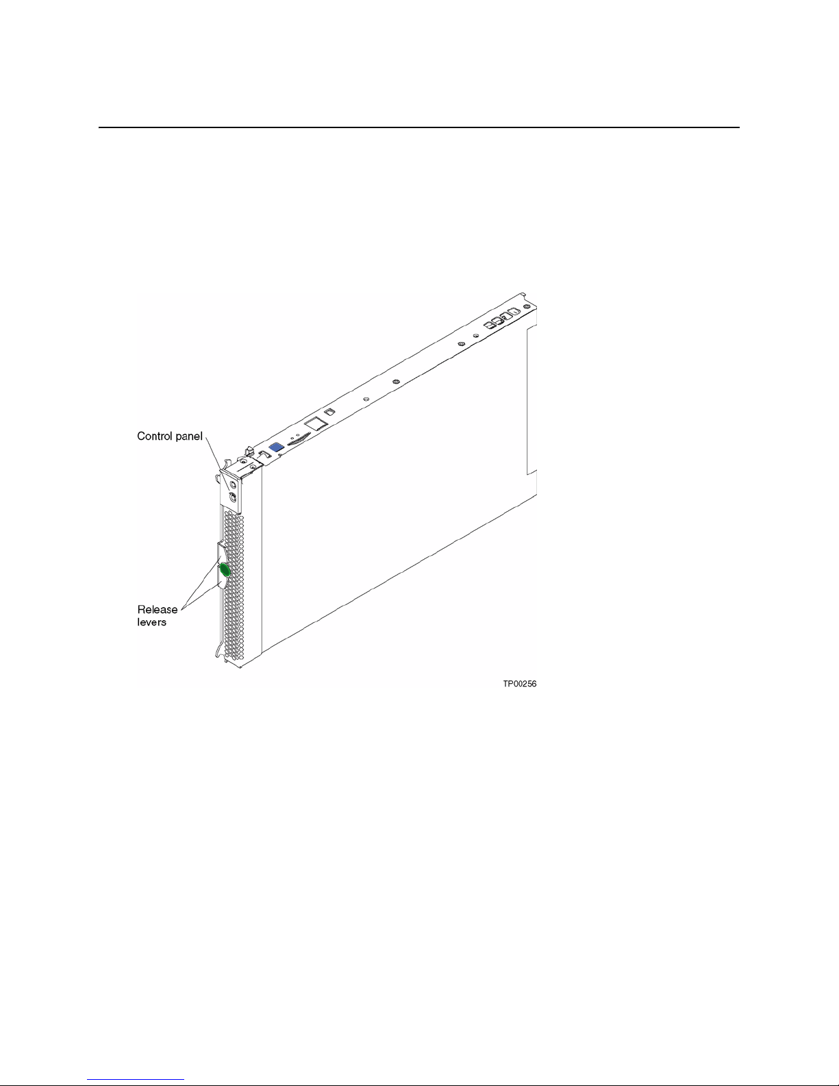
Blade server controls and LEDs
This section describes the controls and light-emitting diodes (LEDs) on your blade server.
NOTE
✏
The control panel is shown in the closed (normal) position in this illustration.
6 SBXL52: Hardware Maintenance Manual and Troubleshooting Guide
Page 21

CD/diskette/USB select button: Press this button to associate the CD-ROM drive, diskette drive,
and USB port with this blade server.
NOTE
✏
The CD-ROM driv e, diskette dri v e, ke yboard and mouse in the SBCE unit are viewed as USB
devices by the blade server operating system.
The LED on this button flashes while the request is being processed, then is steady when the
ownership of the CD-ROM drive, diskette drive, and USB port has been transferred to this blade
server. If the button does not respond, verify that switching support is enabled in the SBCE unit.
✏
NOTE
It can take approximately 20 seconds for the operating system in the switched-to blade server
to recognize the CD-ROM drive, diskette drive, and USB port, or the keyboard, video, and
mouse.
1. The system-error LED might light, and a KVM allocation error might be logged, if the
change in ownership for the CD-ROM drive, diskette drive, and USB port, or the
keyboard, video, and mouse takes more than 8 seconds. The system-error LED will go of f
after the ownership change is complete.
2. It can take up to 48 seconds after a blade server is initially turned on before you can
attempt to switch KVM control to that blade server.
Blade-error LED: When this amber LED is lit, it indicates that a system error has occurred in the
blade server.
Information LED: When this amber LED is lit, it indicates that information about a system error
for this blade server has been placed in the SBCE system error log.
Location LED: When this blue LED is lit, it has been turned on remotely by the system
administrator to aid in visually locating the blade server . The location LED on the SBCE unit will be
on also.
Blade server power, controls, and indicators 7
Page 22

Activity LED: When this green LED is on, it indicates that there is hard-disk-drive or network
activity.
Power-on LED: This green LED indicates the power status of the blade server in the following
manner:
• Flashing rapidly – The service processor on the blade server is handshaking with the SBCE
management module.
• Flashing slowly – The blade server has power but is not turned on.
• Steady – The blade server has power and is turned on.
Keyboard/mouse/video select button: Press this b utton to associate the keyboard port, mouse port,
and video port with this blade server. The LED on this button flashes while the request is being
processed, then is steady when the ownership of the keyboard, mouse, and video has been
transferred to this blade server. If the button does not respond, verify that switching support is
enabled in the SBCE unit.
Notes:
1. The operating system in a blade server must provide USB su pp ort for that blade server to
recognize and use the keyboard, mouse, CD-ROM dri ve, and disk ette dri ve. The SBCE unit uses
USB for internal communication with these devices.
2. It can take approximately 20 seconds to switch the keyboard, video, and mouse or the CD-ROM
drive, diskette drive, and USB port to the blade server.
a. The system-error LED might light, and a KVM allocation error might be logged, if the
change in ownership for the CD-ROM drive, diskette drive, and USB port, or the keyboard,
video, and mouse takes more than 8 seconds. The system-error LED will go off after the
ownership change is complete.
b. It can take up to 48 seconds after a blade server is initially turned on before you can attempt
to switch KVM control to that blade server.
3. If a blade server is under heavy load, it can take several minutes before it enumerates the USB
devices connected to it. If control of the KVM and media tray is switched away from the blade
server before this enumeration is complete, a USB device installation error might be received.
Do not switch KVM control between blade servers until the mouse and keyboard are both
working on the blade server that has control of the KVM and media tray.
4. If you install Microsoft Windows 2000 on the blade server while it is not the current owner of
the keyboard, video, and mouse, a delay of up to one minute occurs the first time you switch the
keyboard, video, and mouse to the blade server. During this one-time-only delay, the blade
server Device Manager enumerates the keyboard, video, and mouse and loads the device driv ers.
All subsequent switching takes place in the normal keyboard-video-mouse switching time
frame.
5. The location LED can be turned off through the SBCE management-module Web interface.
8 SBXL52: Hardware Maintenance Manual and Troubleshooting Guide
Page 23
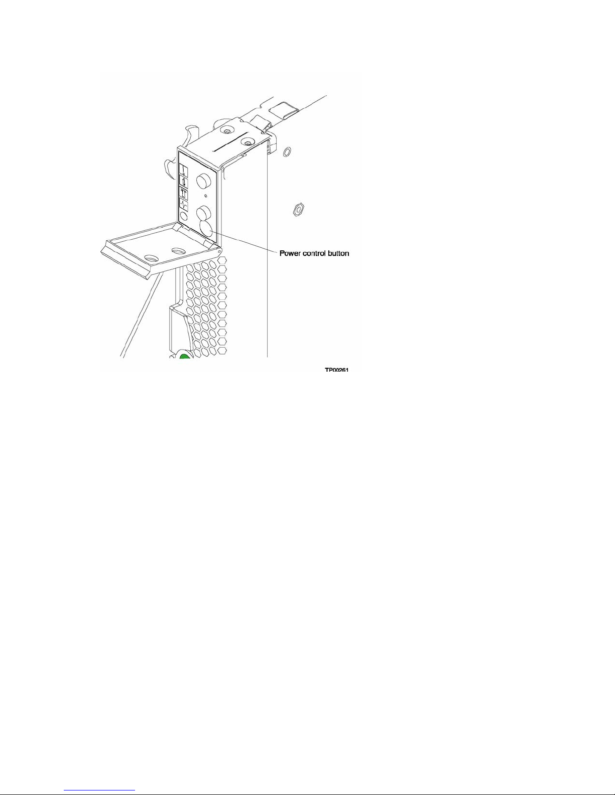
Power-control button: This button is located behind the control panel door. Press this button to
manually turn the blade server on or off.
NOTE
✏
This button has effect only if local power control is enabled for the blade server. Local power
control is enabled and disabled through the SBCE management module Web interface.
Blade server power, controls, and indicators 9
Page 24

<This page intentionally left blank>
10 SBXL52: Hardware Maintenance Manual and Troubleshooting Guide
Page 25

4 Configuration
The following configuration programs are provided with your blade server:
• Configuration/Setup Utility program
This is part of the basic input/output system (BIOS) code in your blade server. Use it to change
interrupt request (IRQ) settings, set the date and time, and set passwords. See “Using the
Configuration/Setup Utility program” for more information.
• PXE boot agent utility program
The Preboot eXecution Environment (PXE) boot agent utility program is part of the BIOS code
in the blade server. Use it to select the boot protocol and other boot options, to display the PXE
setup prompt or to disable it, to set the prompt display duration, and to select a power
management option. For information about using this utility, see “Using the PXE boot agent
utility program” on page 14.
Using the Configuration/Setup Utility program
This section provides the instructions to start the Configuration/Setup Utility program and
descriptions of the menu choices.
Starting the Configuration/Setup Utility program
Complete the following steps to start the Configuration/Setup Utility program:
1. Turn on the blade server and watch the monitor screen.
2. When the message Press F1 for Configuration/Setup appears, press F1.
3. Follow the instructions that appear on the screen.
Configuration/Setup Utility menu choices
The following choices are on the Configuration/Setup Utility main menu. Depending on t he version
of the BIOS code in your blade server, some menu choices might differ slightly from these
descriptions.
• System Summary
Select this choice to display configuration information, including the type, speed, and cache
sizes of the microprocessors and the amount of installed memory. When you make conf iguration
changes through other options in the Configuration/Setup Utility program, the changes are
reflected in the system summary; you cannot change settings directly in the system summary.
This choice is on the full and limited Configuration/Setup Utility menus.
• System Information
Select this choice to display information about your blade server. When you make configu ration
changes through other options in the Configuration/Setup Utility program, some of those
changes are reflected in the system information; you cannot change settings directly in the
system information.
This choice is on the full Configuration/Setup Utility main menu.
11
Page 26

— Product Data
Select this choice to view the model of your blade server, the serial number , and the re vision
level or issue date of the BIOS and diagnostics code stored in electrically erasable
programmable ROM (EEPROM).
• Devices and I/O Ports
Select this choice to view or change assignments for devices and input/output (I/O) ports.
Select this choice to enable or disable the integrated IDE and Ethernet controllers.
— The default setting is Enable for the IDE and Ethernet controllers. If you select Disable, the
system will not configure the disabled device, and the operating system will not detect the
device. (This is equivalent to disconnecting the device.)
• Date and Time
Select this choice to set the system date and time, in 24-hour format (hour:minute:second). This
choice is on the full Configuration/Setup Utility main menu only.
You can set a time to be added or subtracted from the system time that is sent to the service
processor each time the blade server is started. Use the number keys to type the hours and
minutes and + or − to add or subtract from the system time. If you want the system clock time to
be the same as the service processor clock time, leave the value set at its default of 0.
• System Security
Select this choice to set a power-on password. See “Using passwords” on page 14 for more
information about the password.
• Start Options
Select this choice to view or change the start options. This choice appears only on the full
Configuration/Setup Utility main menu. Start options take effect when you start your blade
server.
✏
NOTE
To set the startup sequence, which is the order in which the blade server checks devices to
find a boot record, you must use the SBCE management-module Web interface.
You can set keyboard operating characteristics, such as whether the blade server starts with the
keyboard number lock on or off. You can enable the blade server to run without a diskette drive
or keyboard.
You can enable or disable the Preboot eXecution Environment (PXE) option for either of the
integrated Gigabit Ethernet controllers. The default setting for this menu item is Enabled, which
enables the PXE option for the selected controller . To disable this option for a Gigabit Ethernet
controller, select Disabled.
If you enable the boot fail count, the BIOS default settings will be restored after three
consecutive failures to find a boot record.
You can enable a virus-detection test that checks for changes in the boot record when the blade
server starts.
• Advanced Setup
Select this choice to change settings for advanced hardware features.
12 SBXL52: Hardware Maintenance Manual and Troubleshooting Guide
Page 27

Important: The server might malfunction if t hese options are incorrectly configured. Follo w the
instructions on the screen carefully.
— System Partition Visibility
Select this choice to specify whether the System Partition is to be visible or hidden.
— Memory Settings
Select this choice to manually enable a pair of memory DIMMs.
If a memory error is detected during POST or memory configuration, the blade server
automatically disables the failing memory pair and continues operating with reduced
memory capacity. After the problem is corrected, you must manually enable the memory
connectors. Use the arrow keys to highlight the rows representing the pair that you want to
enable; then, use the arrow keys to select Enable.
— CPU Options
Select this choice to enable or disable the microprocessor cache. In addition, you can set the
microprocessor cache mode to write-back (WB) or write-through (WT). Write-back caching
generally provides better system performance.
— PCI Bus Control
Select this choice to view and set interrupts for PCI devices and to configure the masterlatency-timer value for the blade server.
— Integrated System Management Processor Setti ngs
Select this choice to enable or disable the Reboot on System NMI option on the menu. If
you enable this option, the blade server will automatically restart 60 seconds after the
service processor issues a non-maskable interrupt (NMI) to the blade server.
• Error Logs
Select this choice to view or clear the POST error log.
— Select POST Error Log to view the three most recent error codes and messages that the
system generated during POST.
From the POST Error Log menu, select Clear event/error logs to clear the Error log.
• Save Settings
Select this choice to save the changes you have made in the settings.
• Restore Settings
Select this choice to cancel the changes you have made in the settings and restore the previous
settings.
• Load Default Settings
Select this choice to cancel the changes you have made in the settings and restore the factory
settings.
• Exit Setup
Select this choice to exit from the Configuration/Setup Utility program. If you have not saved
the changes you have made in the settings, you are asked whether you want to save the changes
or exit without saving them.
Configuration 13
Page 28

Using passwords
From the System Security choice, you can set, change, and delete a power-on password.
Power-on password
If you set a power-on password, you must type the power-on password to complete the system
startup, and you have access to the full Configuration/Setup Utility menu.
You can use any combination of up to seven characters (A–Z, a–z, and 0–9) for the password. Keep
a record of your password in a secure place.
If you forget the power-on password, you can regain access to the blade server through one of the
following methods:
• Remove the blade server battery, wait 15 minutes, then reinstall the battery.
• Change the position of the power-on password override switch (switch 8 on switch block 2 on
the system board) to bypass the power-on password check the next time the blade server is
turned on. You can then start the Configuration/Setup Utility program and change the power-on
password. You do not need to move the switch back to the previous position after the password
is overridden. See “Switches and jumpers” on page 31 for the location of switch block 2.
✏
NOTE
Shut down the operating system, turn off the blade server, and remove the blade server
from the SBCE unit to access the switches.
Using the PXE boot agent utility program
This program is a built-in, menu-driven configuration utility program that you can use to:
• Select the boot protocol and other boot options
• Select whether to display the PXE setup prompt and the display duration
• Select a power management option
✏
NOTE
The RPL selection for the boot protocol option is not supported for this server.
Starting the PXE boot agent utility program
Complete the following steps to start the PXE boot agent utility program:
1. Turn on the server.
2. When the Broadcom NetXtreme Boot Agent vX.X.X prompt appears, press Ctrl+S.
Notes:
a. If the PXE setup prompt is not displayed, use the Configuration/Setup Utility program to set
the enable Ethernet PXE/DHCP option.
b. By default, you have 2 seconds after the prompt appears on the screen to press Ctrl+S.
3. Use the arrow keys or press Enter to select a choice from the menu.
• Press Esc to return to the previous menu.
• Press the F4 key to exit.
14 SBXL52: Hardware Maintenance Manual and Troubleshooting Guide
Page 29

4. Follow the instructions on the screen to change the settings of the selected items; then, press
Enter.
Firmware updates
Intel will periodically make firmware updates available for your blade server. Use the following
table to determine the methods you can use to install these firmware updates.
✏ Important
✏ To avoid problems and to maintain proper system performance, always ensure that the blade
server BIOS, service processor, and diagnostic firmware levels are consistent for all blade
servers within the SBCE unit.
Management
Firmware Update diskette
Blade server BIOS
code
Blade server
diagnostic code
module
Web inter face
YesNoNoNo
YesNoNoNo
Switch module
Web interface
Switch module
Telnet interface
Blade server service
processor code
Yes Yes No No
Configuration 15
Page 30

Updating the service processor firmware
The service processor in your blade server provides the following features:
• Continuous health monitoring and control
• Configurable notification and alerts
• Event logs that are timestamped, saved in nonvolatile memory , an d can be attached to e-mail
alerts
• Remote graphics console redirection
• Point-to-point protocol (PPP) support
• Remote power control
• Remote firmware update and access to critical server settings
• Around-the-clock access to the blade server, even if the server is turned off
At some time, you might need to flash the service processor to apply the latest firmware. Obtain the
latest firmware for your blade server service processor from your Intel Support Representative. Use
the management-module Web interface to flash the service processor. The Web interface is described
in the Intel Server System SBCE Installation and User’s Guide on the Resource CD.
Configuring the Gigabit Ethernet controllers
Two Ethernet controllers are inte grated on the blade s erv er syste m board. Each controller provides a
1000-Mbps full-duplex interface for connecting to one of the Ethernet-compatible switch mod ules in
I/O module bays 1 and 2, which enables simultaneous transmission and reception of data on the
Ethernet local area network (LAN). Each Ethernet controller on the system board is routed to a
different switch module in I/O module bay 1 or bay 2. The routing from Ethernet controller to I/O
module bay will vary based on blade server type and the operating system that is installed. See
“Blade server Ethernet controller enumeration” on page 17 for information about how to determine
the routing from Ethernet controller to I/O module bay for your blade server.
✏
NOTE
Other types of blade servers, that are installed in the same SBCE unit as this SBXL52 blade
server might have different Ethernet controller routing. See the documentation that comes with
the other blade servers for detailed information.
You do not need to set any jumpers or configure the controllers for the blade server operating
system. However, you must install a device driver to enable the blade server operating system to
address the Ethernet controllers. For device dri v ers and information about configuring your Ethernet
controllers, see the Broadcom NetXtreme Gigabit Ethernet Software CD that comes with your blade
server. For updated information about configuring the controllers, contact your Intel Support
Representative.
Your Ethernet controllers support failover, which provides automatic redundancy for your Ethernet
controllers. You can configure either one of the integrated Ethernet controllers as the primary
Ethernet controller. If you have conf igured the controllers for failo ver and the primary link fails, the
secondary controller takes over . When the primary link is restored, the Ethernet traff ic switches back
to the primary Ethernet controller. (See your operating system device driver documentation for
information about configuring for failover.)
16 SBXL52: Hardware Maintenance Manual and Troubleshooting Guide
Page 31

Important: To support failover on the blade server Ethernet controllers, the Ethernet switch
modules in the SBCE unit must have identical conf igurat ions to each other.
Blade server Ethernet controller enumeration
The enumeration of the Ethernet controllers in a blade server is operating-system dependent. You
can verify the Ethernet controller designations a blade server uses through your op eratin g system
settings.
The routing of an Ethernet controller to a particular I/O module bay depends on the type of blade
server. You can verify which Ethernet controller is routed to which I/O module bay by using the
following test:
1. Install only one Ethernet switch module in I/O module bay 1.
2. Make sure the ports on the switch module are enabled (Switch Tasks > Management >
Advanced Switch Management in the management module We b-based user interface).
3. Enable only one of the Ethernet controllers on the blade server. Note the designation the blade
server operating system has for the controller.
4. Ping an external computer on the network connected to the switch module. If you can ping the
external computer, the Ethernet controller you enabled is associated with the switch module in
I/O module bay 1. The other Ethernet controller in the blade server is associated with the switch
module in I/O module bay 2.
Two Ethernet switch modules are required to use both dual Ethernet channels of the blade server.
One Ethernet switch module is installed in the SBCE unit and is fully functional with blade server
integrated Ethernet channel ETH0. If the second blade server integrated Ethernet channel ETH1 is
configured, it is unable to communicate with network resources.
Within the SBCE unit, Ethernet switch modules are physically wired independently to the integrated
Ethernet controller channels of each blade server: the ETH0 Ethernet controller channel on the blade
server is wired to the top Ethernet switch module and the ETH1 Ethernet controller channel on the
blade server is wired to the bottom Ethernet switch module. Two Ethernet switch modules are
required to use both blade server Ethernet channels.
See the SBCE Installation and User’s Guide for more information.
Configuration 17
Page 32

<This page intentionally left blank>
18 SBXL52: Hardware Maintenance Manual and Troubleshooting Guide
Page 33

5 Diagnostics
This section provides basic troubleshooting information to help you solve some common problems
that might occur with your blade server.
If you cannot locate and correct the problem using the information in this section, see Appendix A,
“Getting help and technical assistance,” on page 93 for more information.
General checkout
The server diagnostic programs are stored in the upgradeable read-only memory (ROM). These
programs test the major components of your blade server.
If you cannot determine whether a problem is caused by the hardware or by the software, you can
run the diagnostic programs to confirm that the hardware is working properly.
When you run the diagnostic programs, a single problem might cause several error messages. When
this occurs, work to correct the cause of the first error message. After the cause of the first error
message is corrected, the other error messages might not occur the next time you run the test.
Notes:
1. If multiple error codes are displayed, diagnose the first error code that is displayed.
2. If the server stops with a POST error, go to “POST error codes” on page 76.
3. If the blade server stops and no error is displayed, go to “Undetermined problems” on page 100.
4. For safety information, see “Electrical Safety” on page vi.
5. For intermittent problems, check the error log.
6. If blade front panel shows no LEDs, verify blade status and errors in SBCE web interface; also
see “Undetermined problems” on page 100.
7. If device errors occur, see “Error symptoms” on page 83.
19
Page 34

001
USE THE FOLLOWING PROCEDURE TO CHECKOUT THE SERVER.
1. Turn off the server and all external devices, if attached.
2. Check all cables and power cords.
3. Set all display controls to the middle position.
4. Turn on all external devices.
5. Turn on the server.
6. Record any POST error messages that are displayed on the screen. If an error is
displayed, look up the first error in the “POST error codes” on page 76.
7. Check the information LED panel Blade Error LED; if it is on, see “Identifying
problems using the light path diagnostics” on page 24.
8. Check the System Error log. If an error was recorded by the system, see Chapter 9,
“Symptom-to-FRU index,” on page 69.
9. Start the diagnostic programs.
10. Check for the following responses:
• One beep.
• Readable instructions or the main menu.
002
DID YOU RECEIVE BOTH OF THE CORRECT RESPONSES?
NO. Find the failure symptom in Chapter 9, “Symptom-to-FRU index,” on page 69.
YES. Run the diagnostic programs. If necessary, see “Diagnostic programs and error
messages” on page 21.
If you receive an error, see Chapter 9, “Symptom-to-FRU index,” on page 69.
If the diagnostic programs were completed successfully and you still suspect a problem, see
“Undetermined problems” on page 100.
Diagnostic tools overview
The following tools are available to help you identify and solve hardware-related problems:
• POST beep codes
The power-on self-test beep codes indicate the detection of a problem.
— One beep indicates successful completion of POST.
— More than one beep indicates that POST detected a problem. Error messages also appear
during startup if POST detects a hardware-configuration problem.
See “Beep symptoms” on page 69 for more information.
• Error symptom charts
These charts list problem symptoms and steps to correct the problems. See “Error symptoms” on
page 83 for more information.
The built-in system diagnostic programs are upgradeable read-only memory (R OM). These
programs test the major components of your blade server
• Light path diagnostics feature
20 SBXL52: Hardware Maintenance Manual and Troubleshooting Guide
Page 35

Use the light path diagnostics feature to identify system errors quickly. See the “Light path
diagnostics* feature overview” on page 24 for more information.
POST error logs
When you turn on the server, it performs a series of tests to check the operation of server
components and some of the options that are installed in the blade server. This series of tests is
called the power-on self-test, or POST.
If POST finishes without detecting any problems, a single beep sounds, and the first screen of your
operating system or application program appears.
If POST detects a problem, more than one beep sounds, and an error message appears on your
screen. See “Beep symptoms” on page 69 and “POST error codes” on page 76 for more information.
Notes:
1. If you have a power-on password set, you must type the password and press Enter, when
prompted, before POST will continue.
2. A single problem might cause several error messages. When this occurs, work to correct the
cause of the first error message. After you correct the cause of the first error message, the other
error messages usually will not occur the next time you run the test.
The POST error log contains the three most recent error codes and messages that the system
generated during POST. The System Error log refers you to the management module log, which can
be accessed through the SBCE unit.
Viewing error logs from the Configuration/Setup Utility program
Start the Configuration/Setup Utility program; then, select Error Logs from the main menu. See
“Using the Configuration/Setup Utility program” on page 11 for more information.
Diagnostic programs and error messages
The server diagnostic programs are stored in ROM on the system board. These programs are the
primary method of testing the major components of your server.
Diagnostic error messages indicate that a problem exists; they are not intended to be used to identify
a failing part. Troubleshooting and servicing of complex problems that are indicated by error
messages should be performed by trained service personnel.
Sometimes the first error to occur causes additional errors. In this case, the blade server displays
more than one error message. Always follow the suggested action instructions for the first error
message that appears.
The following sections contain the error codes that might appear in the detailed test log and
summary log when the diagnostic programs are run.
The error code format is as follows:
fff-ttt-iii-date-cc-text message
where:
fff is the three-digit function code that indicates the function being tested when the
error occurred. For example, function code 089 is for the microprocessor.
Diagnostics 21
Page 36

ttt is the three-digit failure code that indicates the exact test failure that was
encountered. (These codes are for trained service personnel; see “Diagnostic error
codes” on page 73)
iii is the three-digit device ID. (These codes are for trained service personnel; see
“Diagnostic error codes” on page 73)
date is the date that the diagnostic test was run and the error recorded.
cc is the check value that is used to verify the validity of the information.
text message is the diagnostic message that indicates the reason for the problem.
Text messages
The diagnostic text message format is as follows:
Function Name: Result (test specific string)
where:
Function Name
is the name of the function being tested when the error occurred. This corresponds to the
function code (fff) shown in the error code format in the previous section.
Result
can be one of the following:
Passed This result occurs when the diagnostic test is completed without any errors.
Failed This result occurs when the diagnostic test discovers an error.
User Aborted
This result occurs when you stop the diagnostic test before it is complete.
Not Applicable
This result occurs when you specify a diagnostic test for a device that is not
present.
Aborted This result occurs when the test could not proceed, for example, because of
the system configuration.
Warning This result occurs when a possible problem is reported during the
diagnostic test, such as when a device driver is not found.
test specific string
is additional information that you can use to analyze the problem.
Starting the diagnostic programs
You can press F1 while running the diagnostic programs to obtain help information. You also can
press F1 from within a help screen to obtain online documentation from which you can select
different categories. To exit from the help information and return to where you left off, press Esc.
Complete the following steps to start the diagnostic programs:
1. Turn on the blade server and watch the screen.
NOTE
✏
When running the diagnostic programs, make sure that the blade server controls the
needed components for the tests, including the CD-ROM drive, diskette drive, and USB
port. You can use the selection buttons on the blade server to make necessary adjustments.
22 SBXL52: Hardware Maintenance Manual and Troubleshooting Guide
Page 37

2. When the message F2 for Diagnostics appears, press F2.
3. Type the appropriate password; then, press Enter.
4. After the diagnostic programs start, select either Extended or Basic from the top of the screen.
5. When the Diagnostic Programs screen appears, select the test you want to run from the list that
appears; then, follow the instructions on the screen.
Notes:
a. If the blade server stops during testing and you cannot continue, restart the blade server and
try running the diagnostic programs again. If the problem remains, replace the component
that was being tested when the blade server stopped.
b. The keyboard and mouse (pointing device) tests assume that a keyboard and mouse are
attached to the SBCE and that the blade server controls them.
c. If you run the diagnostic programs with either no mouse or a mouse attached to the SBCE
unit that is not controlled by the blade server, you will not be able to navigate between test
categories using the Next Cat and Prev Cat buttons. All other functions provided by
mouse-selectable buttons are also available using the function keys.
d. You can view server configuration information (such as system configuration, memory
contents, and device drivers) by selecting Hardware Info from the top of the screen.
If the diagnostic programs do not detect any hardware errors but the problem persists during normal
server operations, a software error might be the cause. If you suspect a software problem, see the
information that comes with the software package.
Viewing the test log
When the tests are completed, you can view the test log by selecting Utility from the top of the
screen and then selecting View Test Log.
Notes:
1. You can view the test log only while you are in the diagnostic programs. When you exit the
diagnostic programs, the test log is cleared (saved test logs are not affected). To save the test log
so that you can view it later, click Save Log on the diagnostic programs screen and specify a
location and name for the saved log file.
2. To save the test log to a diskette, you must use a diskette that you have formatted yourself; this
function does not work with preformatted diskettes. If the diskette has sufficient space for the
test log, the diskette may contain other data.
Diagnostic error message tables
For descriptions of the error messages that might appear when you run the diagnostic programs, see
“Diagnostic error codes” on page 73
Notes:
1. Depending on your server configuration, some of these error messages might not appear when
you run the diagnostic programs.
2. If diagnostic error messages ap pear that are not listed in t he error message tables, mak e sure that
your server has the latest levels of BIOS, service processor, and diagnostics microcode installed.
Diagnostics 23
Page 38

Error symptoms
This section describes methods for troubleshooting other error symptoms.
Error symptom charts
You can use the error symptom charts to find solutions to problems that ha v e definite sy mptoms (see
“Error symptoms” on page 83).
If you cannot find the problem in the error symptom charts, go to “Starting the diagnostic programs”
on page 22 to test the blade server.
Small computer system interface messages
This information only applies if a storage expansion unit is available. If your receive a SCSI error
message when running the SCSI Select Utility program, see “SCSI error codes” on page 95.
✏ NOTE
If your server does not hav e a hard disk dri v e, ignore an y message that in dicates that the BIOS
is not installed.
Light path diagnostics* feature overview
If the system-error LED on the system LED panel on the front or rear of the SBCE unit is lit, one or
more error LEDs on the SBCE unit components also might be on. These LEDs help identify the
cause of the problem.
Identifying problems using the light path diagnostics
This section provides the information to identify, using the light path diagnostics, problems that
might arise during installation. To locate the actual component that caused the error, you must locate
the lit error LED on that component.
For example:
24 SBXL52: Hardware Maintenance Manual and Troubleshooting Guide
Page 39

A blade server error has occurred and you have noted that the blade server blade-error LED is lit on
the blade server control panel. You then:
1. R emove the blade server from the SBCE unit.
2. Place the blade server on a flat, non-conductive surface.
3. Remove the cover from the blade server.
4. Press and hold the light path diagnostics button to relight the LEDs that were lit before you
removed the blade server from the SBCE unit. The LEDs will remain lit for as long as you press
the button, to a maximum of 25 seconds.
NOTE
✏
Power is av ailable to relight the light pat h diagnostics LEDs for a short period of time after the
blade server is removed from the SBCE unit. During that period of time, you can relight the
light path diagnostics LEDs for a maximum of 25 seconds (or less, depending on the number
of LEDs that are lit and the length of time the blade server is removed from the SBCE unit) b y
pressing the light path diagnostics button. The light path diagnostics power present LED
(CR111) lights when the light path diagnostics button is pressed if po wer is av ailable to relight
the blade-error LEDs. If the light path diagnostics power present LED does not light when the
light path diagnostics button is pressed, no power is available to light the blade-error LEDs
and they will be unable to provide any diagnostic information.
Use the table at “Light path diagnostics” on page 81 to help determine the cause of the error and the
action you should take.
Memory errors
If a memory problem occurs, take the following actions before replacing a DIMM:
1. Reseat both DIMMs in the bank.
2. Check for a memory type mismatch in the bank.
3. Run the diagnostic programs.
For more information about memory, see “Installing memory modules” on page 37
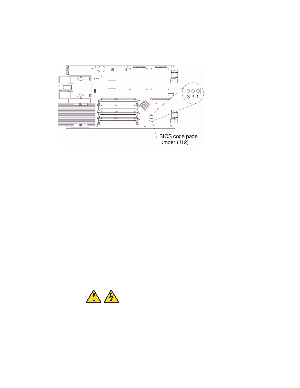
Recovering the BIOS code
If your BIOS code has become damaged, such as from a power failure during a flash update, the
blade server may appear to be nonfunctional (no video, no beeps). You can recover your BIOS code
using the BIOS code page jumper (J12) and a BIOS flash diskette.
✏
NOTE
To obtain a BIOS flash diskette, contact your Intel Support Representative.
The flash memory of your server consists of a primary page and a backup page. The J12 jumper
controls which page is used to start the blade server. If the BIOS code in the primary page is
damaged, you can use the backup page to start the blade server; then, start the BIOS flash diskette to
restore the BIOS code to the primary page.
To recover the BIOS code, complete the following steps:
1. Turn off the blade server.
Diagnostics 25
Page 40
2. R emove the blade server from the SBCE unit (see “Removing the blade server from the SBCE
unit” on page 33).
3. R emove the cover (see “Opening the blade server cover” on page 33).
4. Loca te jumper J12 (BIOS code page jumper) on the system board.
5. Move J12 to pins 2 and 3 to enable BIOS recovery mode.
6. Replace the cover and reinstall the blade server in the SBCE unit, making sure the media tray is
selected by the relevant blade server.
7. Insert the BIOS flash diskette into the diskette drive.
8. R estart the blade server. The system begins the power-on self-test (POST).
9. Select 1 - Update POST/BIOS from the menu that contains various flash (update) options.
10. When you are prompted whether you want to move the current POST/BIOS image to the backup
ROM location, press N.
Attention: If you press Y, the damaged BIOS will be copied into the secondary page.
11. When you are prompted whether you want to save the current code to a diskette, press N.
12. Select your language (0 through 5) and press Enter to accept your choice.
13. Attention: Do not restart the blade server at this time. Remove the flash diskette from the
diskette drive.
14. Turn off the blade server, remove it from the SBCE, and remove the cover of the blade server.
15. Move J12 to pins 1 and 2 to return to normal startup mode.
16. Replace the cover and reinstall the blade server in the SBCE unit; then restart the blade server.
The system starts up.
xxCAUTION:
Hazardous energy is present when the blade server is connected to the power
source. Always replace the blade cover before installing the blade server.
26 SBXL52: Hardware Maintenance Manual and Troubleshooting Guide
Page 41

6 Installing options
This chapter provides instructions for adding options to your blade server. Some option-removal
instructions are provided in case you need to remove one option to install another.
Installation guidelines
Before you begin to install options in your blade server, read the Intel® Server Boards and Server
Chassis Safety Information included on the Resource CD.
• Read 1 “SBXL52 safety and regulatory information” on page v and the guidelines in “Handling
static-sensitive devices.” This information will help you work safely with your blade server and
options.
• Back up all important data before you make changes to disk drives.
• Before you remove a hot-swap blade server from the SBCE unit, you must shut down the
operating system and turn off the blade server. You do not have to shut down the SBCE unit
itself.
System reliability considerations
T o help ensure proper cooling and system reliability, make sure that microprocessor socket 2 always
contains either the microprocessor heat sink filler or a microprocessor and heat sink.
Handling static-sensitive devices
Attention: Static electricity can damage electronic devices and your system. To avoid damage,
keep static-sensitive devices in their static-protective packages until you are ready to install them.
To reduce the possibility of electrostatic discharge, observe the following precautions:
• Limit your movement. Movement can cause static electricity to build up around you.
• Handle the device carefully, holding it by its edges or its frame.
• Do not touch solder joints, pins, or exposed printed circuitry.
• Do not leave the device where others can handle and possibly damage the device.
• While the device is still in its static-protectiv e package, touch it to an unpainted metal part of the
system unit for at least two seconds. (This drains static electricity from the package and from
your body.)
• Remove the device from its package and install it directly into your system unit without setting it
down. If it is necessary to set the device down, place it in its static-protective package. Do not
place the device on your blade server cover or on a metal table.
• T ake additional care when handling devices during cold weather because heating reduces indoor
humidity and increases static electricity.
27
Page 42
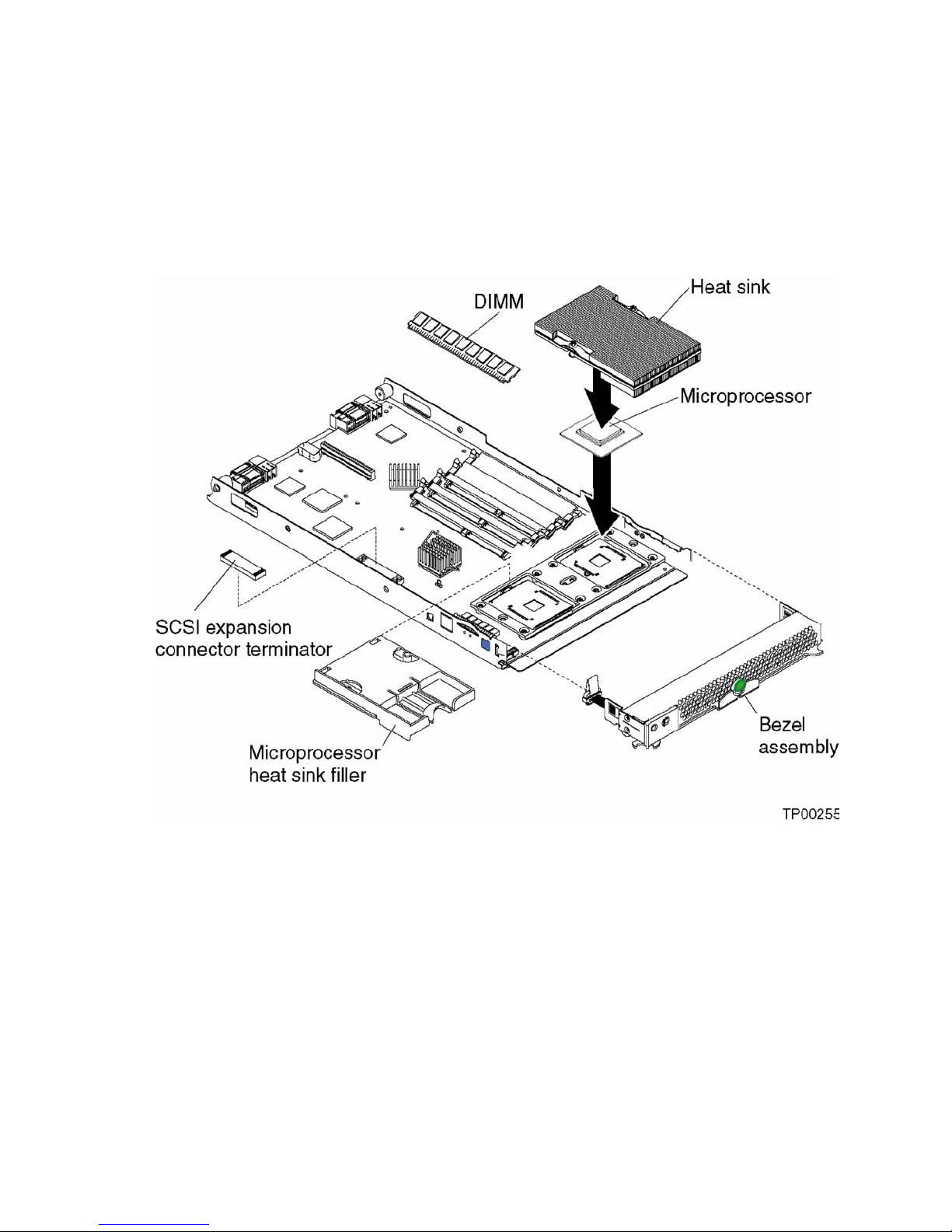
Major components of the SBXL52 blade server
The following illustration shows the locations of major components in your blade server. You need
to remove the blade server from the SBCE unit and remove the blade server cover to see the
components.
✏
NOTE
The illustrations in this document might differ slightly from your hardware.
28 SBXL52: Hardware Maintenance Manual and Troubleshooting Guide
Page 43

System board illustration
The following illustration sho ws the location of the system-board components, including connectors
for user-installable options.
✏
NOTE
The SCSI expansion connector (J8) requires a terminator unless an expansion option is
connected to it.
Installing options 29
Page 44

System board LED locations
The following illustration shows the location of the LEDs on the system board. You might need to
refer to this illustration when solving problems with the blade server. Yo u need to remove the blade
server from the SBCE unit, open the cover, and press the light path diagnostics button to light any
error LEDs that were turned on during processing.
✏
NOTE
Power is av ailable to relight the light pat h diagnostics LEDs for a short period of time after the
blade server is removed from the SBCE unit. During that period of time, you can relight the
light path diagnostics LEDs for a maximum of 25 seconds (or less, depending on the number
of LEDs that are lit and the length of time the blade server is removed from the SBCE unit) b y
pressing the light path diagnostics button. The light path diagnostics power present LED
(CR111) lights when the light path diagnostics button is pressed if po wer is av ailable to relight
the blade-error LEDs. If the light path diagnostics power present LED does not light when the
light path diagnostics button is pressed, no power is available to light the blade-error LEDs
and they will be unable to provide any diagnostic information.
30 SBXL52: Hardware Maintenance Manual and Troubleshooting Guide
Page 45
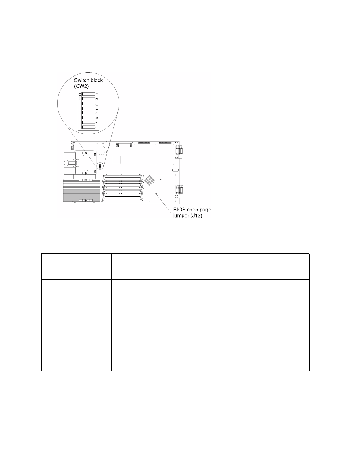
Switches and jumpers
The following illustration shows the location of the switches and jumpers on the system board.
Switches
Table 1 describes the function of each switch on switch block (SW2).
Switch
number Default value
1 through 4 Off Reserved.
5 Off Power-on override. When toggled to On, this switch forces the blade server to turn
6 through 7 Off Reserved
8 Off Power-on password override. Changing the position of this switch bypasses the
Table 1. Switch block (SW2)
Switch
description
on, overriding the power-on button. The power-on override switch should be used for
debug purposes only and should not be used to override management module
control of the server.
power-on password check the next time the blade server is turned on and starts the
Configuration/Setup Utility program so that you can change or delete the power-on
password. You do not need to move the switch back to the default position after the
password is overridden.
See “Using passwords” on page 14 for additional information about the power-on
password.
Installing options 31
Page 46

Jumpers
When the BIOS code page jumper (J12) is moved from pins 1 and 2 to pins 2 and 3, you can start the
blade server from a backup BIOS page (see “Recovering the BIOS code” on page 25). The default
position is pins 1 and 2.
✏
NOTE
If you start the blade server from the backup page because the primary BIOS page has become
damaged, you need to flash the primary BIOS code.
32 SBXL52: Hardware Maintenance Manual and Troubleshooting Guide
Page 47
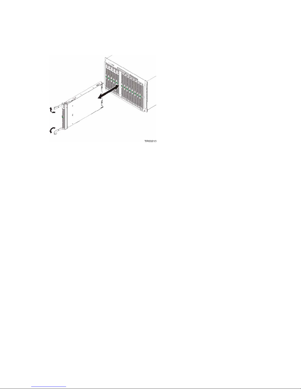
Removing the blade server from the SBCE unit
The following illustration shows how to remove the blade server from the SBCE unit.
Attention:
• To maintain proper system cooling, do not operate the SBCE unit for more than one minute
without either a blade server, expansion unit, or filler blade installed in each blade bay.
• Note the bay number. Reinstalling a blade server into a different bay than the one from which it
was removed could ha ve unintended consequences. Some configuration information and update
options are established according to bay number; if you reinstall the blade server into a dif ferent
bay, you might need to reconfigure the blade server.
Complete the following steps to remove the blade server:
1. If the blade server is operating, shut down the operating system; then, press the power-control
button (behind the blade server control panel door) to turn off the blade server. See “Blade server
controls and LEDs” on page 6 for more information about the location of the power-control
button.
Attention: Wait at least 30 seconds, until the drives stop spinning, before proceeding to the
next step.
2. Open the two release levers as shown in the illustration. The blade server moves out of the bay
approximately 0.6 cm (0.25 inch).
3. Pull the blade server out of the bay. Spring-loaded do ors further back in the bay mo v e into place
to cover the bay temporarily.
4. Place either a filler blade or another blade server in the bay within one minute. The recessed
spring-loaded doors will move out of the way as you insert the blade server or filler blade.
Opening the blade server cover
The following illustration shows how to open the cover on the blade server.
Installing options 33
Page 48

Complete the following steps to open the blade server cover:
1. R eview “Electrical Safety” on page vi and “Installation guidelines” on page 27.
2. Carefully lay the blade server down on a flat, non-conductive surface, with the cover side up.
3. Press the blade-cover release on each side of the blade server and lift the cov er open, as shown in
the illustration.
4. Lay the cover flat, or lift it from the blade server.
xxCAUTION:
Hazardous energy is present when the blade server is connected to the power
source. Always replace the blade cover before installing the blade server.
34 SBXL52: Hardware Maintenance Manual and Troubleshooting Guide
Page 49

Removing the blade server bezel assembly
To install certain options you must first remove the blade server bezel assembly. The following
illustration shows how to remove the bezel assembly from a blade server.
Complete the following steps to remove the blade server bezel assembly:
1. R eview “Electrical Safety” on page vi and “Installation guidelines” on page 27.
2. O pe n the blade server cover.
3. Press the bezel-assembly release and pull the bezel assembly away from the blade server
approximately 1.2 cm (0.5 inch).
4. D isconnect the control-panel cable from the control-panel connector.
5. Pull the bezel assembly away from the blade server.
6. Store the bezel assembly in a safe place.
Installing IDE hard disk drives
Your blade server has two connectors on the system board for installing optional 2.5-inch IDE hard
disk drives. Each IDE connector is on a separate bus.
Two IDE drives can be used to implement and manage RAID level-1 under both the Linux and
Microsoft Windows 2000 operating systems.
Attention: To maintain proper system cooling, do not operate the SBCE unit for more than one
minute without either a blade server, expansion unit, or filler blade installed in each blade bay.
Installing options 35
Page 50

Complete the following steps to install a 2.5-inch IDE hard disk drive.
✏
NOTE
Do not install a hard disk drive in IDE connector 2 if you intend to also install an optional I/O
expansion card. The I/O expansion card occupies the same area as the second IDE hard disk
drive.
1. R eview “Electrical Safety” on page vi and “Installation guidelines” on page 27.
2. Shut down the operating system, turn off the blade server, and remov e the blade server from the
SBCE unit. See “Removing the blade server from the SBCE unit” on page 33 for instructions.
3. C arefully lay the blade server on a flat, non-conductive surface.
4. O pe n the blade server cover. See “Opening the blade server cover” on page 33 for instructions.
5. Insert the riser card from the option kit into an IDE connector on the blade server system board.
Important: Drives must be installed in the following order: IDE connector 1 (J13) first, then
IDE connector 2 (J62).
6. Place the hard disk drive tray from the option kit over the riser card as shown in the illustration,
aligning the tray with the screw holes on the system board. Two of the screw holes have screws
in them.
7. Remove the tray temporarily; then, remove the two screws from the screw holes on the system
board and replace the tray. Secure the tray to the system board with screws from the kit.
8. Set any jumpers or switches on the hard disk drive.
Important: Both IDE hard disk drives must be set to Master.
Attention: Do not press on the top of the hard disk drive. Pressing the top could damage the
hard disk drive.
36 SBXL52: Hardware Maintenance Manual and Troubleshooting Guide
Page 51

9. Place the hard disk drive into the tray and push it, from the rear edge of the hard disk drive, into
the connector on the riser card until the hard disk drive moves past the lever at the back of the
tray. The hard disk drive clicks into place.
10. If you have other options to install or remove, do so now; otherwise, go to “Completing the
installation” on page 51.
Installing memory modules
You can increase the amount of memory in your blade server b y installing memory-module options.
When you install memory, you must install a pair of matched dual inline memory modules
(DIMMs).
Notes:
1. The system board contains four DIMM connectors and supports two-way memory interleaving.
2. The DIMM options available for your blade server are 256 MB, 512 MB, and 1 GB. The blade
server supports a minimum of 512 MB and a maximum of 4 GB of system memory.
3. A minimum of two DIMMs, installed in the DIMM 3 and DIMM 4 memory connectors (J2 and
J6, respectively), is required. When you install additional DIMMs, be sure to install them as a
pair, in DIMM connectors 1 and 2 (J1 and J5).
Install the DIMMs in the following order:
Pair DIMM connectors
First 3 and 4 (J2, J6)
Second 1 and 2 (J1, J5)
4. Both DIMMs in a pair must be the same size, speed, type, and technology. You can mix
compatible DIMMs from various manufacturers.
5. The second pair does not have to be DIMMs of the same size, speed, type, and technology as the
first pair.
6. Install only 2.5 V, 184-pin, double-data-rate (DDR), PC2100, registered synchronous dynamic
random-access memory (SDRAM) with error correcting code (ECC) DIMMs. These DIMMs
must be compatible with the latest PC2100 SDRAM Registered DIMM specification, which is
available from http://www.jedec.org/. For a list of supported options for your blade server,
reference Intel’s Memory Qualification List or contact your Intel Support Representative.
7. PC2100 DIMMs are backward-compatible and work in the PC1600 sockets.
8. Installing or removing DIMMs changes the configuration information for the blade server.
Therefore, after installing or removing a DIMM, you must change and save the new
configuration information by using the Configuration/Setup Utility program. When you restart
the blade server, the system displays a message indicating that the memory configuration has
changed. Start the Configuration/Setup Utility program and select Save Settings. See
“Configuration/Setup Utility menu choices” on page 11 for more information.
The following illustration shows how to install DIMMs on the system board.
Installing options 37
Page 52

Before you begin, read the documentation that comes with your option.
Complete the following steps to install a DIMM:
1. R eview “Electrical Safety” on page vi and “Installation guidelines” on page 27.
2. Shut down the operating system, turn off the blade server, and remov e the blade server from the
SBCE unit. See “Removing the blade server from the SBCE unit” on page 33 for instructions.
3. C arefully lay the blade server on a flat, non-conductive surface.
4. O pe n the blade server cover. See “Opening the blade server cover” on page 33 for instructions.
5. Loca te the DIMM connectors on the system board. Determine the connectors into which you
will install the DIMMs. (See note 3 on page 37)
6. Touch the static-protective package that contains the DIMM option to any unpainted metal
surface on the SBCE chassis or any unpainted surface on any other grounded rack component.
Then, remove the DIMM from the package.
7. To install the DIMMs, repeat the following steps for each DIMM that you install:
a. Turn the DIMM so that the DIMM keys align correctly with the connector on the system
board.
Attention: To avoid breaking the retaining clips or damaging the DIMM connectors,
handle the clips gently.
b. Insert the DIMM by pressing the DIMM along the guides into the connector. Be sure that
the retaining clips snap into the closed positions.
Important: If there is a gap between the DIMM and the retaining clips, the DIMM has not
been properly installed. In this case, open the retaining clips and remove the DIMM; then,
reinsert the DIMM.
8. If you have other options to install or remove, do so now; otherwise, go to “Completing the
installation” on page 51.
Installing an additional microprocessor
Your blade server supports two microprocessors. With two microprocessors, your blade server can
operate as a symmetric multiprocessing (SMP) server. With SMP, certain operating systems and
application programs can distribute the processing load between the microprocessors. To use SMP,
38 SBXL52: Hardware Maintenance Manual and Troubleshooting Guide
Page 53

obtain an SMP-capable operating system. For a list of supported operating systems and other
options, contact your Intel Support Representative .
Attention: To ensure proper blade server operation when you install a second microprocessor,
observe the following precautions:
• Always install microprocessors that have the same cache size and type, the same clock speed,
and identical internal and external clock frequencies (including system bus speed).
• Ensure that the microprocessor with the lowest feature set is the startup (bootstrap)
microprocessor installed in the Microprocessor 1 socket (location U66).
Notes:
1. Thoroughly review the documentation that comes with the microprocessor, so that you can
determine whether you need to update the blade server BIOS code. Contact your Intel Support
Representative for the latest level of BIOS code for your blade server.
2. The microprocessor sockets in this server contain built-in termination for the microprocessor
bus; therefore, no terminator card is required if a second microprocessor is not installed in
microprocessor socket 2. Howev er , for proper airflo w, this socket must contain a microprocessor
heat-sink filler, sometimes called a microprocessor baffle.
3. The microprocessor speeds are automatically set for this server; therefore, you do not need to set
any microprocessor frequency-selection jumpers or switches.
The following illustration shows how to install the second microprocessor on the system board.
Complete the following steps to install an additional microprocessor:
1. R eview “Electrical Safety” on page vi and “Installation guidelines” on page 27.
2. Shut down the operating system, turn off the blade server, and remov e the blade server from the
SBCE unit. See “Removing the blade server from the SBCE unit” on page 33 for instructions.
3. C arefully lay the blade server on a flat, non-conductive surface.
4. O pe n the blade server cover (see “Opening the blade server cover” on page 33 for instructions).
5. Remove the bezel assembly (see “Removing the blade server bezel assembly” on page 35 for
instructions).
6. Loca te the microprocessor socket on the system board.
Installing options 39
Page 54
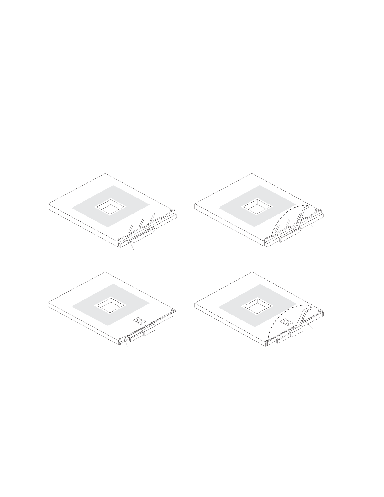
7. Remove the heat-sink filler.
8. Install the microproces sor:
a. Remove the protective cover , tape, or label from the surf ace of the microprocessor socket, if
one is present.
b. Touch the static-protective package containing the new microprocessor to any unpainted
metal surface on the SBCE chassis or any unpainted surface on any other ground ed rack
component; then, remove the microprocessor from the package.
c. Rotate the locking lever on the microprocessor socket from its closed and locked position
until it stops or clicks in the fully open position (approximately a 135° angle), as shown.
Attention: You must ensure that the locking lever on the microprocessor socket is in the
fully open position before you insert the microprocessor in the socket. Failure to do so might
result in permanent damage to the microprocessor, microprocessor socket, and system
board.
Lever
fully
open
Lever closed
or
Lever
fully
open
Lever closed
d. Center the microprocessor over the microprocessor socket. Align the triangle on the corner
of the microprocessor with the triangle on the corner of the socket and carefully press the
microprocessor into the socket.
Attention:
• Do not use excessive force when pressing the microprocessor into the socket.
• Make sure that the microprocessor is oriented and aligned correctly in the socket before
you try to close the lever.
40 SBXL52: Hardware Maintenance Manual and Troubleshooting Guide
Page 55

e. Carefully close the lever to secure the microprocessor in the socket.
9. Install a heat sink on the microprocessor:
a. Remove the plastic protective cover from the bottom of the heat sink.
Attention:
1) Do not set down the heat sink after you remove the plastic cover.
2) Do not touch the thermal grease on the bottom of the heat sink. Touching the thermal
grease will contaminate it. If the thermal grease on the microprocessor or heat sink
becomes contaminated, contact your service technician.
b. Align and place the heat sink on top of the microprocessor in the retention bracket, grease
side down. Press firmly on the heat sink.
c. Using a screwdriver, secure the heat sink to th e retention bracket on the system board using
the two captive mounting screws. Press firmly on the screws and tighten them, alternating
between them. Do not overtighten the screws.
10. If you have other options to install or remove, do so now; otherwise, go to “Completing the
installation” on page 51.
Installing an I/O expansion card
You can add an optional I/O expansion card to your blade server to give the blade server additional
network connections for communicating on a network.
Attention: When you add an I/O expansion card, you must make sure that the I/O modules in bays
3 and 4 on the SBCE unit both support the I/O expansion card network-interface type. For example,
if you add an Ethernet expansion card to your blade server, the modules in I/O module bays 3 and 4
on the SBCE unit must both be compatible with the Ethernet expansion card. All other I/O
expansion cards installed on other blade servers in the SBCE unit must also be compatible with these
switch modules. In this example, you could then install two Ethernet Switch Modules, two pass-thru
modules, or one Ethernet Switch Module and one pass-thru module. Because pass-thru modules are
compatible with a variety of I/O expansion cards, installing two pass-thru modules would allow use
of several different types of compatible I/O expansion cards within the same SBCE unit.
✏ Important
Installation of an I/O expansion card requires removal of the hard disk drive installed in IDE
connector 2. The I/O expansion card occupies the same space as this hard disk drive and replaces it.
You can not install a hard disk drive in IDE connector 2 while an I/O expansion card is installed in
the blade server.
Installing options 41
Page 56

• If the hard disk drive installed in IDE connector 2 contains any information that you want to
keep, back it up to another storage device.
• If the hard disk drive installed in IDE connector 2 is part of a RAID array, unconfigure this
RAID array before removing the hard disk drive. See your operating system documentation for
instructions.
The following illustration sho ws how to install an I/ O expansion card on the blade serv er . The card is
installed near IDE connector 2.
Complete the following steps to install an I/O expansion card:
1. R eview “Electrical Safety” on page vi and “Installation guidelines” on page 27.
2. Shut down the operating system, turn off the blade server, and remov e the blade server from the
SBCE unit (see “Removing the blade server from the SBCE unit” on page 33 for information).
3. C arefully lay the blade server on a flat, non-conductive surface.
4. O pe n the cover (see “Opening the blade server cover” on page 33 for instructions).
42 SBXL52: Hardware Maintenance Manual and Troubleshooting Guide
Page 57

5. If an IDE hard disk drive is in IDE connector 2, remove the hard disk drive and tray (save the
screws that secured the tray to the system board); otherwise, remove the two screws near IDE
connector 2 that secure the system board to the chassis, as shown in the illustration.
6. Install the I/O expansion card:
a. Install the I/O expansion card tray. Secure the tray to the system board with the scre ws from
the option kit, as shown in the illustration.
b. Orient the I/O expansion card as shown in the illustration.
c. Slide the notch in the narrow end of the card into the raised hook on the tray; then, gently
pivot the wide end of the card into the I/O e xpan sio n card co nn ecto rs, as shown in the
illustration.
✏
NOTE
For device driver and configuration information to complete the installation of the I/O
expansion card, see the documentation that comes with the option. Some documentation
might also be on the SBCE Documentation CD that comes with the SBCE unit.
7. If you have other options to install or remove, do so now; otherwise, go to “Completing the
installation” on page 51.
Installing a SCSI storage expansion unit
To use SCSI hard disk drives with your blade server, install a SCSI storage expansion unit, such as
Intel’s SBSCSI SCSI storage e xpansion unit, on the blade serv er. You will then be able to install two
3.5-inch, hot-swap, SCSI, 1-inch (26 mm) slim-high hard disk drives in the expansion unit, for use
by the blade server. The SCSI controller in the SCSI storage expansion unit supports RAID level-1
(embedded mirroring).
✏ Important
✏ To avoid potential performance and reliability problems when configuring or replacing drives in a
mirrored configuration, ensure that the storage capacities and speeds of the drives are
identical.
Notes:
1. After you install the SCSI storage expansion unit on your blade server, the blade server and
expansion unit become a single unit that occupies two blade bays in the SBCE unit.
2. To ensure proper cooling and system reliability, make sure that each of the SCSI hard disk drive
bays on the SCSI storage expansion unit contains either a hot-swap SCSI hard disk drive or a
filler panel.
For a list SCSI hard disk driv es supported b y your blade serv er , refer to Intel’s "T ested Hardw are and
Operating Systems List" for this product.
The following illustration shows how to install the SCSI storage expansion unit on the blade server.
Installing options 43
Page 58

Complete the following steps to install the SCSI storage expansion unit:
1. R eview “Electrical Safety” on page vi and “Installation guidelines” on page 27.
2. Shut down the operating system, turn off the blade server, and remov e the blade server from the
SBCE unit (see “Removing the blade server from the SBCE unit” on page 33 for instructions).
3. C arefully lay the blade server on a flat, non-conductive surface.
4. R emove the blade server cover.
a. Open the blade server cover (see “Opening the blade server cover” on page 33 for
instructions) and lift it off the blade server.
b. Store the cover in a safe place.
5. Locate the SCSI connector on the system board and remove the terminator from the connector.
6. Install the SCSI storage expansion unit:
a. Orient the storage expansion unit as shown in the illustration.
b. Lower the storage expansion unit so that the slots at the rear slide down onto the pins at the
rear of the blade server.
44 SBXL52: Hardware Maintenance Manual and Troubleshooting Guide
Page 59

c. Pivot the storage expansion unit closed and press it firmly into place until the cover-release
latches click. The connector on the expansion unit automatically aligns with and plugs into
the SCSI expansion connector (J8) on the system board.
7. Inse rt the combined blade server and expansion unit into two adjacent SBCE unit bays.
✏
NOTE
When any blade server or option is in blade bays 7 through 14, power modules must be
present in power bays 1 and 2, and power modules must be present in power bays 3 and 4.
8. Turn on the blade server.
9. If you have not already done so, install the LSI device drivers for your operating system. LSI
device drivers are on the Resource CD that comes with the SBCE unit. You can also get the
latest version of the drivers from your Intel Support Representative.
With the storage expansion unit installed on your blade server, you can install up to two hot-swap
SCSI hard disk drives in the option and configure them for embedded mirroring (RAID lev el1). Each
SCSI device must have a unique SCSI ID. This ID enables the SCSI controller in the I/O expansion
card to identify the device and ensure that different de vices on the same SCSI channel do not attempt
to transfer data simultaneously. The SCSI IDs for the hard disk drives in the expansion unit are
permanent (not configurable). Table 2 lists the SCSI IDs for the hard disk drives that are installed in
the expansion unit. See “Installing a SCSI hot-swap hard disk drive” for instructions for installing
hard disk drives.
Device SCSI ID
Drive bay 1 0
Drive bay 2 1
Table 2. SCSI IDs for hot-swap hard disk drives in the expansion unit
✏
NOTE
SCSI ID 7 is usually reserved for the SCSI controller; however, this SCSI ID is changeable
through the LSI configuration program program utility.
Use the Configuration/Setup Utility program in the blade server to enable or disable the SCSI
controller in the storage expansion unit. See the documentation that comes with the storage
expansion unit for information about configuring the storage expansion unit and SCSI hard disk
drives.
Installing a SCSI hot-swap hard disk drive
If you have installed a SCSI storage expansion unit on the blade server, you can install up to two
SCSI hot-swap hard disk drives in the bays in the expansion unit.
If a hot-swap hard disk drive in the expansion unit fails, you can replace it without turning off the
blade server. Therefore, you have the advantage of continuing to operate your blade server while a
hard disk drive in this unit is removed or installed.
Each hot-swap hard disk drive has two indicator LEDs. If the amber hard disk drive status LED for a
hard disk drive is lit continuously, that hard disk drive is faulty and must be replaced.
Installing options 45
Page 60
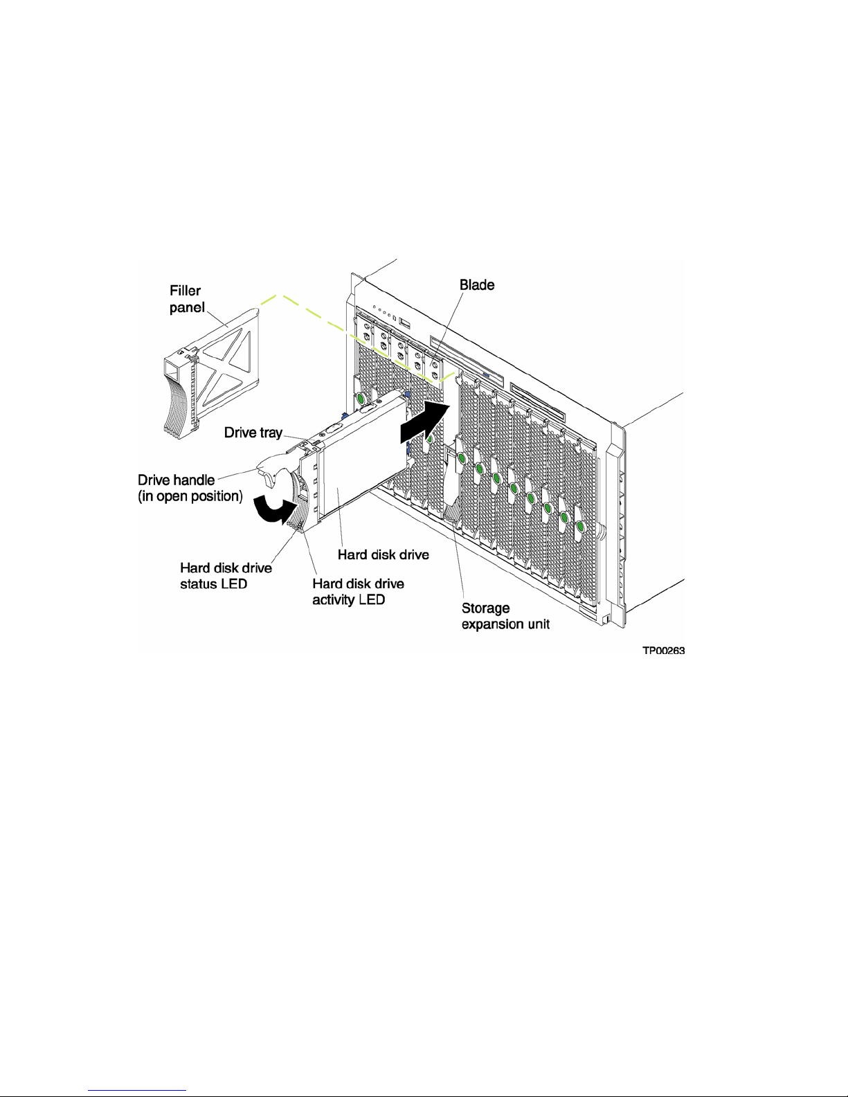
Each hot-swap hard disk driv e that you plan to install must be mounted in a hot-sw ap-dri ve tray. The
hard disk drive must have a Single Connector Attachment (SCA) connector. Hot-swap-drive trays
come with the hot-swap hard disk drives.
For a list of SCSI hard disk drives supported by your blade server, refer to the "Intel Tested
Hardware and Operating System List".
The following illustration shows how to install a SCSI hot-swap hard disk drive.
Complete the following steps to install a SCSI hot-swap hard disk drive in a storage expansion unit.
Attention: To maintain proper system cooling, do not operate the SBCE unit for more than one
minute without either a hot-swap hard disk drive or a f iller panel installed i n each storage e xpansion
unit bay.
1. R eview “Electrical Safety” on page vi and “Installation guidelines” on page 27.
2. Remove the filler panel from one of the empty hot-swap bays by inserting your finger into the
depression at the top of the filler panel and pulling it away from the expansion unit.
3. Install the SCSI hot-swap hard disk drive:
a. Ensure that the tray handle is open (that is, perpendicular to the hard disk drive).
b. Align the hard disk drive assembly with the guide rails in the bay.
c. Gently push the hard disk drive assembly into the bay until it stops.
d. Push the tray handle to the closed (locked) position.
e. Check the hard disk drive LEDs to verify that the hard disk drive is operating properly.
46 SBXL52: Hardware Maintenance Manual and Troubleshooting Guide
Page 61

• If the amber hard disk drive status LED for a hard disk driv e is lit continuously , that hard
disk drive is faulty and needs to be replaced.
• If the green hard disk drive activity LED is flashing, the hard disk drive is being
accessed.
See the documentation that comes with the expansion unit for information about configuring the
expansion unit and SCSI hard disk drives.
Installing options 47
Page 62

Replacing a SCSI hot-swap hard disk drive
If a hard disk drive in the storage expansion unit fails, you can replace it without turning off the
blade server.
Complete the following steps to replace a SCSI hot-swap hard disk driv e in a storage expansion unit
hot-swap bay.
Attention: To maintain proper system cooling, do not operate the SBCE unit for more than one
minute without either a hot-swap hard disk drive or a f iller panel installed i n each storage e xpansion
unit bay.
1. R eview “Electrical Safety” on page vi and “Installation guidelines” on page 27.
2. Locate the defective hard disk drive (look for an amber status LED that is lit on the front of the
hard disk drive).
3. Ma ke sure the ha rd disk drive has stopped spinning.
4. Move the handle on the hard disk drive to the open position (perpendicular to the hard disk
drive), and pull the hot-swap hard disk drive assembly from the bay.
5. Within one minute, install the replacement hard disk drive in the hot-swap bay (see “Installing a
SCSI hot-swap hard disk drive” on page 45 for instructions).
48 SBXL52: Hardware Maintenance Manual and Troubleshooting Guide
Page 63

Replacing the battery
The lithium battery must be handled correctly to avoid possible danger. If you replace the battery,
you must adhere to the following instructions.
If you replace the original lithium battery with a heavy-metal battery or a battery with heavy-metal
components, be aware of the follo wing en vironmental consideration. Batteries and accumulators that
contain heavy metals must not be disposed of with normal domestic waste. They will be taken back
free of charge by the manufacturer, distributor, or representative, to be recycled or disposed of in a
proper manner.
✏
NOTE
After you replace the battery , you mu st recon figure your blade server and reset the system
date and time.
xxCAUTION:
When replacing the lithium battery, use only same or an equivalent type battery
recommended by the manufacturer. If your system has a module containing a
lithium battery, replace it only with the same module type made by the same
manufacturer. The battery contains lithium and can explode if not properly used,
handled, or disposed of.
Do not:
• Throw or immerse into water
• Heat to more than 100°C (212°F)
• Repair or disassemble
Dispose of the battery as required by local ordinances or regulations.
Complete the following steps to replace the battery:
1. R eview “Electrical Safety” on page vi and “Installation guidelines” on page 27.
2. Follow any special handling and installation instructions supplied with the battery.
3. Turn off the blade server and remove the blade from the SBCE unit (see “Removing the blade
server from the SBCE unit” on page 33 for instructions).
4. O pe n the blade server cover (see “Opening the blade server cover” on page 33 for instructions).
5. Loca te the battery on the system board.
Installing options 49
Page 64

6. Remove the battery:
a. Use your finger to press down on one side of the battery; then, slide the battery out from its
socket. The spring mechanism will push the battery out toward you as you slide it from the
socket.
✏
b. Use your thumb and index finger to pull the battery from under the battery clip.
NOTE
You might need to lift the battery clip slightly with your f ingernail to make it easier to
slide the battery.
✏
NOTE
After you remove the battery, ensure that the battery clip is touching the base of the
battery socket by pressing gently on the clip.
7. Insert the new battery:
a. Tilt the battery so that you can insert it into the socket, under the battery clip.
b. As you slide it under the battery clip, press the battery down into the socket.
8. C l ose the blade server cover (see “Closing the blade server cover” on page 52).
50 SBXL52: Hardware Maintenance Manual and Troubleshooting Guide
Page 65

xxCAUTION:
Hazardous energy is present when the blade server is connected to the power
source. Always replace the blade cover before installing the blade server.
9. Reinsert the blade server into the bay in the SBCE unit.
10. Turn on the blade server.
11. Start the blade server Configuration/Setup Utility program and set configuration parameters as
needed. See “Using the Configuration/Setup Utility program” on page 11 for information.
Completing the installation
To complete the installation, perform the following tasks. Instructions for each task are in the
following sections.
1. Reinstall the blade server bezel assembly, if you removed it (see “Installing the blade server
bezel assembly”).
2. Close the blade server cover, unless you installed the SCSI storage expansion unit option (see
“Closing the blade server cover” on page 52).
xxCAUTION:
Hazardous energy is present when the blade server is connected to the power
source. Always replace the blade cover before installing the blade server.
3. Reinstall the blade server into the SBCE unit (see “Installing the blade server in the SBCE unit”
on page 54).
4. Turn on the blade server (see “Turning on the blade server” on page 5).
5. For certain options, run the blade server Configuration/Setup Utility program (see “Updating
your blade server configuration” on page 56).
✏
NOTE
If you have just connected the power cords of your SBCE unit to electrical outlets, you will
have to wait until the power-on LED on the blade server flashes slowly before pressing the
power-control button on a blade server.
Installing the blade server bezel assembly
The following illustration shows how to install the bezel assembly on the blade server.
Installing options 51
Page 66

Complete the following steps to install the blade server bezel assembly.
1. R eview “Electrical Safety” on page vi and “Installation guidelines” on page 27..
2. Connect the control-panel cable to the control-panel connector on the system board.
3. Carefully slide the bezel assembly onto the blade server as shown in the illustration, until it
clicks into place.
Closing the blade server cover
Important: The blade server cannot be inserted into the SBCE unit until the cover is installed and
closed, or a SCSI storage expansion unit is installed. Do not attempt to override this protection.
The following illustration shows how to close the blade server cover.
52 SBXL52: Hardware Maintenance Manual and Troubleshooting Guide
Page 67

Complete the following steps to close the blade server cover:
1. R eview “Electrical Safety” on page vi and “Installation guidelines” on page 27.
Installing options 53
Page 68

2. If you removed the blade bezel assembly, replace it now. See “Installing the blade server bezel
assembly” on page 51 for instructions.
3. Lower the cover so that the slots at the rear slide down onto the pins at the rear of the blade
server, as shown in the illustration. Before closing the cover, check that all components are
installed and seated correctly and that you have not left loose tools or parts inside the blade
server.
4. Pivot the cover to the closed position as shown in the illustration, until it clicks into place.
Installing the blade server in the SBCE unit
Complete the following steps to install a blade server in the SBCE unit.
xxCAUTION:
Hazardous energy is present when the blade server is connected to the power
source. Always replace the blade cover before installing the blade server.
1. R eview “Electrical Safety” on page vi and “Installation guidelines” on page 27 through
“Handling static-sensitive devices” on page 27.
2. If you have not done so already , install any options needed, such as disk drives or memory , in the
blade server.
3. Select the bay for the blade server.
Notes:
a. If the blade server has a SCSI storage expansion unit installed on it, the blade server and
expansion option require two adjacent bays.
b. When any blade server or option is in blade bays 7 through 14, power modules must be
present in power bays 1 and 2, and power modules must be present in power bays 3 and 4.
54 SBXL52: Hardware Maintenance Manual and Troubleshooting Guide
Page 69

c. To help ensure proper cooling, performance, and system reliability, make sure that each of
the blade bays on the front of the SBCE unit has a blade server, expansion unit, or filler
blade installed. Do not operate the SBCE unit for more than one minute without either a
blade server, expansion unit, or filler blade installed in each blade bay.
4. Ensure that the release levers on the blade server are in the open position (perpendicular to the
blade server).
5. Slide the blade server into the bay until it stops. The spring-loaded doors further back in the bay
that cover the bay opening move out of the way as you insert the blade server.
6. Push the release levers on the front of the blade server closed.
7. Turn on the blade server. See “Turning on the blade server” on page 5 for instructions.
8. Verify that the power-on LED on the blade control panel is lit continuously, indicating that the
blade server is receiving power and is turned on.
9. If desired, write identifying information on one of the user labels that come with the blade
server; then, place the label on the SBCE bezel just below the blade server, as shown in the
following illustration.
Important: Do not place the label on the blade server or in any way block the ventilation holes
on the blade server.
10. If you have other blades to install, do so now.
Attention: If you reinstall a blade server that you removed, you must install it in the same bay from
which you removed it. Some blade server configuration information and update options are
established according to bay number. Reinstalling a blade server into a different bay than the one
from which it was removed could ha v e unintended consequences and you might need to reconfigure
the blade server.
If this is the initial installation for a blade server in the SBCE unit, you need to configure the blade
server with the blade server Configuration/Setup Utility and install the blade server operating
system. See “Updating your blade server configuration” on page 56 and Chapter 7, “Installing the
operating system,” on page 57 for details.
Installing options 55
Page 70

Updating your blade server configuration
When you start your blade server for the first time after you add or remove an internal option or an
external SCSI device (if the storage expansion unit has been installed), you might see a message
telling you that the configuration has changed. The blade server Configuration/Setup Utility
program automatically starts so that you can save the ne w conf iguration information. See “Using the
Configuration/Setup Utility program” on page 11 for more information about the
Configuration/Setup Utility program.
Some options have device drivers that you need to install. See the documentation that comes with
your option for information about installing any required device drivers.
Your blade server comes with one or two microprocessors installed on the system board. If your
blade server comes with two microprocessors, or your blade server comes with one microprocessor
and you have installed an additional microprocessor, your blade server can now operate as an SMP
server. Therefore, you might need to upgrade your operatin g system to supp ort SMP. See Chapter 7,
“Installing the operating system,” on page 57 and your operating-system documentation for
additional information.
Input/output connectors and devices
The input/output connectors available to your blade server are supplied by the SBCE unit. See the
documentation that comes with your SBCE unit for information about the input/output connectors.
The blade server has two selection buttons on the control panel: the CD/diskette/USB select button
and the keyboard/mouse/video select button. See “Blade server controls and LEDs” on page 6 for
information about these buttons and their function.
The Ethernet controllers on your blade server communicate with the network through the Ethernetcompatible switch modules on the SBCE unit. Network signals to and from the blade server or any
I/O expansion cards are automatically routed to a same-network-interface switch module through
circuitry in the SBCE unit.
56 SBXL52: Hardware Maintenance Manual and Troubleshooting Guide
Page 71

7 Installing the operating system
This section outlines quick installation procedures for local operating system installations only.
The operating system in the blade server must provide USB support for the blade server to recognize
and use the keyboard, mouse, CD-ROM drive, and diskette drive. The SBCE chassis uses USB for
internal communication with these devices.
Some operating systems, such as Red* Hat Linux* 9.0, permit you to select the type of mouse being
used. If offered this choice, select USB instead of PS/2. Although the mouse is a PS/2-style device,
communication with the mouse is through an internal USB bus in the chassis; therefore, the
operating system in your blade server must recognize the mouse as a USB device.
✏
NOTE
• It can take approximately 20 seconds to switch the keyboard, video, and mouse or the CDROM drive, diskette drive, and USB port to the blade server.
• Although the keyboard attached to the SBCE unit is a PS/2-style keyboard,
communication with it is through a USB bus. When you are running an operating system
that does not have USB drivers, such as in the following instances, the keyboard responds
very slowly.
— Running the blade server integrated diagnostics
— Running a BIOS update diskette on a blade server
— Updating the diagnostics on a blade server
• If you install Microsoft* Windows* Server 2003 on the blade server while it is not the
current owner of the keyboard, video, and mouse, a delay of up to one minute occurs the
first time you switch the keyboard, video, and mouse to the blade server. During this onetime-only delay, the blade server Device Manager enumerates the keyboard, video, and
mouse and loads the device drivers. All subsequent switching takes place in the normal
keyboard-video-mouse switching time frame.
Microsoft* Windows* Server 2003 Enterprise
Edition installation instructions
Complete the following steps to perform a basic installation of Microsoft Windows Server 2003
Enterprise Edition.
• On the blade server on which you are installing the operating system, press the CD select button
to associate that blade server with the CD, diskette, and USB port. Then, press the KVM select
button to associate that blade server with the keyboard, monitor, and mouse.
• Insert the Microsoft Windows Server 2003 Enterprise Edition CD into the CD-ROM drive. The
blade server on which the installation will take place starts from the CD. The message "Setup is
inspecting your blade server's hardware configuration" is displayed.
57
Page 72

• If the blade server has a small computer system interface (SCSI) storage expansion unit
installed, press F6 to install a SCSI or redundant array of independent disks (RAID) device
driver. If the blade server does not have a SCSI storage expansion unit installed, continue with
step 5. Prior to proceeding to step 5, extract the LSI drivers from the system resource cd.
• In the Setup window, specify a controller and press the S key to specify any additional devices
you might want.
• When you are prompted to insert the manufacturer's hardware support diskette to install the
onboard LSI SCSI controller , in sert the d isk ette that contain s the LSI Lo gic PCI SCS/F C device
driver into the diskette drive and press Enter.
• Select the LSI Logic PCI SCSI/FC MPI Miniport device driver and press Enter.
• Specify any additional CD-ROM drives you want to use and press Enter.
• When the Setup window opens, press Enter to install Microsoft Windows Server 2003
Enterprise Edition.
• In the Licensing Agreement window , read the licensing agreement and press the Page Do wn ke y
to scroll to the bottom of the window . Then, click "<F8> I Agree". All hard disk dri v es and driv e
partitions that are available on the blade server are displayed.
• Select one of the following partitioning options:
— To create a partition on a hard disk drive in the blade server , highlight non-partitioned space
for that hard disk drive, and press the C key. You are prompted to indicate how much
available space you want to allocate from the non-partitioned drive. Type the amount of
space (in MB) and press Enter.
— To permanently delete a partition, to allow en ough room to create new partitions, press the D
key when the message, "Are you su re you w a nt to delete this partition?", is displayed. Press
Enter. The same message is displayed again. Press the L key to permanently delete the
partition.
— To permanently delete a partition, to allow en ough room to create new partitions, press the D
key when the message "Are you sure you want to delete this partition?" is displayed. Press
Enter. The same message is displayed again. Press the L key to permanently delete the
partition.
— When you are prompted to choose a file system, select NTFS file system unless you will
configure the blade server for dual boot with an operating system that does not support NT
File System (NTFS). The formatting process will take up to 20 minutes.
• The blade server restarts, and the setup wizard installs Microsoft Windows Server 2003
Enterprise Edition. When the installation is complete, the Welcome window opens.
• Click Next. Setup automatically installs device dri vers and conf igures your blade serv er de vices.
This process takes several minutes to complete. Depending on the optional hardw are that may be
installed, it may be necessary to install device drivers from the appropriate resource cd for the
installed item.
• In the Regional Settings and Language Options window, make the appropriate modif ication and
click Next.
✏
NOTE
To modify your regional settings after you have installed Microsoft Windows Server 2003
58 SBXL52: Hardware Maintenance Manual and Troubleshooting Guide
Page 73

Enterprise Edition, click Control Panel -> Regional Options and mak e the appropriate
modification.
• In the Personalize Your Software window, in the Name field, type your name, and in the
Organizations field, type the organization name. Click Next.
✏
NOTE
The names you type will be used as default blade server names. Applications that you
install on the blade server will use the same information for the product registration and
document identification.
• When you are prompted for the CD-Key, type the CD-Key in the applicable fields. Click Next
• In the Name and Administrator Password window, type the blade server name and password that
you want and click Next. (Notice t hat Setup uses the or ganization name that you specified earlier
as a suggested name for the blade server.)
✏
NOTE
Passwords are case sensitive. Use a combination of uppercase and lowercase letters with
at least one number for your password.
Select or deselect the components you want to include in the installation process. To install a
component, select the check box Next to the component. Components that you do not select will
not be installed. Click Next.
In the Time Zone window, set the current time and zone. To change the date, click the button to
the right of the date. To change the time, highlight the value you want to change and type the
correct value, or use the Up Arrow and Down Arrow keys to make your selection. Click Next.
✏
NOTE
NOTE: Microsoft Windows Server 2003 Enterprise Edition performs many tasks that are
dependent on accurate blade server time and date settings. Be sure to select the correct
time zone for the blade server location to avoid problems.
Microsoft Windows Server 2003 Enterprise Edition will automatically install networking
components. If prompted in the Networking Settings window, select either Typical or Custom
Settings. If you are prompted, type the appropriate network information. Click Next. Disregard
if not prompted for network settings and accept default settings. The network may be configured
at a later time once the system installation has been completed.
In the Workgroup window or Windows Domain window, select one of the following options:
— No, this computer is not on a network, or it is a network without a domain.
— Yes, make this computer a member of the following domain
— Type the workgroup or domain name in the applicable field and click Next.
Setup installs and configures the remaining operating-system components according to the options
you specified. The status is displayed in the Installing Component window. This process will take
several minutes. Setup finishes copying the files and displays the status in the Performing Final
Tasks window. This process takes several minutes.
Installing the operating system 59
Page 74

• Remove the CD from the CD-ROM drive and click Finish. The blade server restarts.
• Press Ctrl+Alt+Delete and log on. The Server W izard starts to help you set up an d conf igure any
additional server components on the blade server.
Red Hat* Linux* 9.0 Server installation
instructions
Complete the following steps to perform a basic installation of Red Hat Linux 9.0 Server.
• On the blade server on which you are installing the operating system, press the CD select button
to associate that blade server with the CD, diskette, and USB port. Then, press the KVM select
button to associate that blade server with the keyboard, monitor, and mouse.
• Insert the Red Hat Linux 9.0 Server CD into the CD-ROM drive. The blade server on which the
installation will take place starts from the CD.
• Select "Okay" to test media. At least
✏
NOTE
NOTE: Do not switch the KVM from the blade server unt il the inst allation has proceeded
to installing the packages after the About to Install window; otherwise, the mouse will
lose functionality.
• Select "Graphical Mode" to begin
• Select "Okay" to test media. You must test at least one cd in order to proceed. If the media tests
okay, proceed with the installation. select "Continue" to proceed.
In the Welcome to Red Hat Linux Version 9.0 window, if you are using the SBXL52 blade
server with SCSI hot-swap hard disk drives, load the Red Hat Linux 9.0 drvblock.img. The
image may be obtained from your Intel support representative or may be obtained from the
SBXL52 resource cd. Copy the image to a diskette and insert the diskette into the diskette drive
when the "Devices" window is displayed.
• In the "Language Selection" window, select the languages in which you want to install the
operating system, and click Next.
• In the "Set Root Password" window, type and confirm your root password. Use the root
password only for administration. Enter the root password for the system an d click "Ne xt" wh en
finished.
• In the "Package Group Selection" window, select the Graphical User Interface (GUI) of choice.
Select the package (application) groups that you want to install. Select Kernel Development if
you are planning to recompile kernels at a later time.
• In the "About to Install" window note the caution. Caution: Once you click "Next" the
installation program will begin. This process can not be undone. If y ou ha v e decided not to
continue with this installation, this is the last point at which you can safely abort the
installation process. Click "Next".
• In the "Installing Packages " window, Red Hat Linux 9.0 starts the installation process.
• In the "Boot Disk Creation " window, insert a boot diskette into your floppy drive and select
"Yes". Click "Next" to create a boot diskette.
60 SBXL52: Hardware Maintenance Manual and Troubleshooting Guide
Page 75

• After completion of the boot diskette, installation is complete. Click next to reboot the system.
• Log in as root user
Installing the operating system 61
Page 76

<This page intentionally left blank.>
62 SBXL52: Hardware Maintenance Manual and Troubleshooting Guide
Page 77

8 Service replaceable units
This chapter describes the removal of server components.
✏ Important
The field replaceable unit (FR U) procedures are intended for trained servicers who are f amiliar with
Intel products. See the parts listing in “System” on page 104 to determine if the component being
replaced is a customer replaceable unit (CRU) or a FRU.
Microprocessor removal
✏ NOTE
• Read “Installation guidelines” on page 27.
• Read the safety notices at “Electrical Safety” on page vi.
• Read “Handling electrostatic discharge-sensitive devices” on page vi
Complete the following steps to remove a microprocessor:
1. Shut down the operating system, turn off the blade server, and remov e the blade server from the
SBCE unit (see “Removing the blade server from the SBCE unit” on page 33).
2. C arefully lay the blade server on a flat, non-conductive surface.
3. O pe n the blade server cover (see “Opening the blade server cover” on page 33 for instructions).
4. Remove the bezel assembly (see “Removing the blade server bezel assembly” on page 35 for
instructions).
5. Identify the microprocessor to be removed.
NOTE
✏
If you are replacing a failed microprocessor, verify that you have selected the correct
microprocessor for replacement (see “Light path diagnostics” on page 81).
6. Remove the heat sink:
a. Loosen one captive screw fully; then, loosen the other captive screw.
Attention: Loosening one screw fully before loosening the other screw will help to break
the thermal bond that adheres the heat sink to the microprocessor.
b. Gently pull the heat sink off of the microprocessor.
7. Rotate the locking lever on the microprocessor socket from its closed and locked position until it
stops or clicks in the fully open position (approximately 135° angle), as shown. Then, see the
documentation provided with the microprocessor option for complete installation instructions.
Attention: You must ensure that the locking lever on the microprocessor socket is in the fully
open position before you insert the microprocessor in the socket. Failure to do so might result in
permanent damage to the microprocessor, microprocessor socket, and system board.
63
Page 78
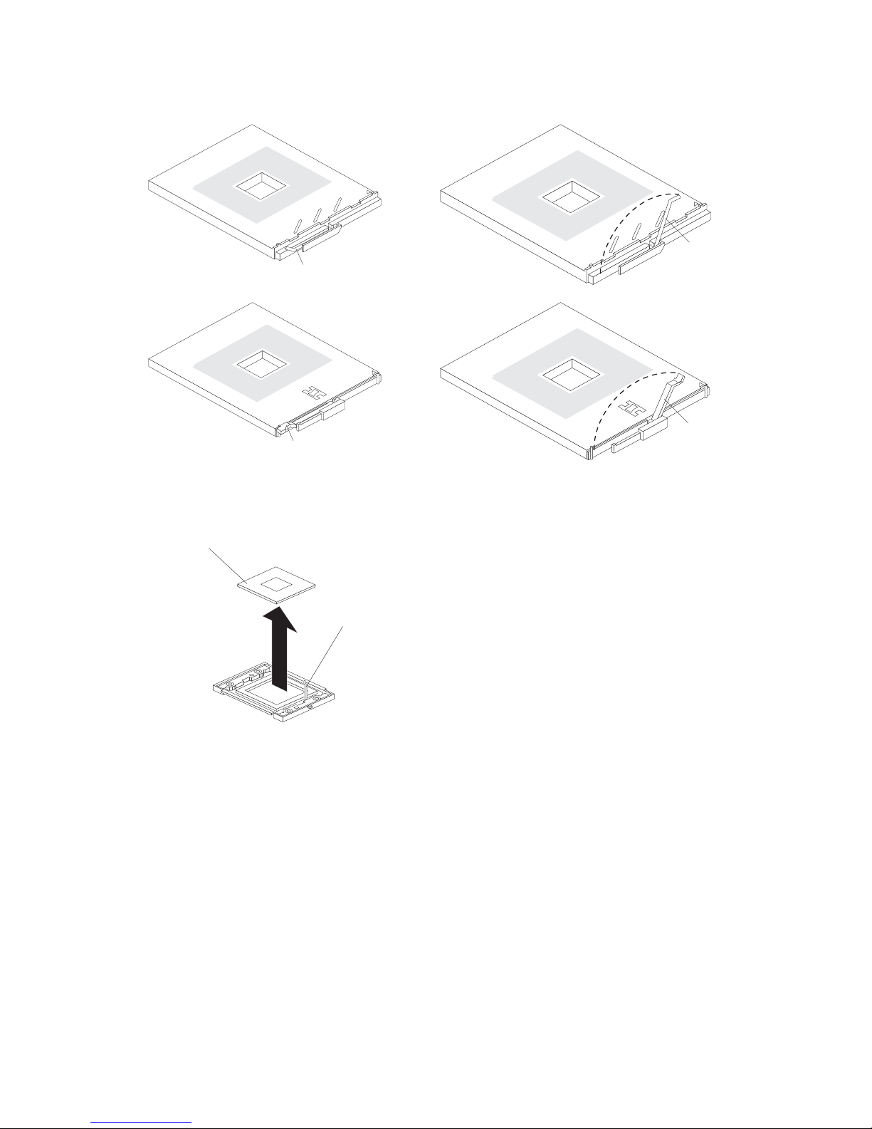
Lever
Lever closed
Lever closed
fully
open
Lever
fully
open
8. Pull the microprocessor out of the socket.
Microprocessor
Microprocessorrelease lever
To install a microprocessor, see “Installing an additional microprocessor” on page 38
Attention: If you are not installing a replacement microprocessor in socket 2, you must reinstall
the microprocessor baffle in that socket.
Thermal grease
This section contains information about removing and replacing th e thermal gr ease between the heat
sink and the microprocessor. The thermal grease must be replaced anytime the heat sink has been
removed from the top of the microprocessor and is going to be reused, or when debris is found in the
grease.
✏
NOTE
64 SBXL52: Hardware Maintenance Manual and Troubleshooting Guide
Page 79
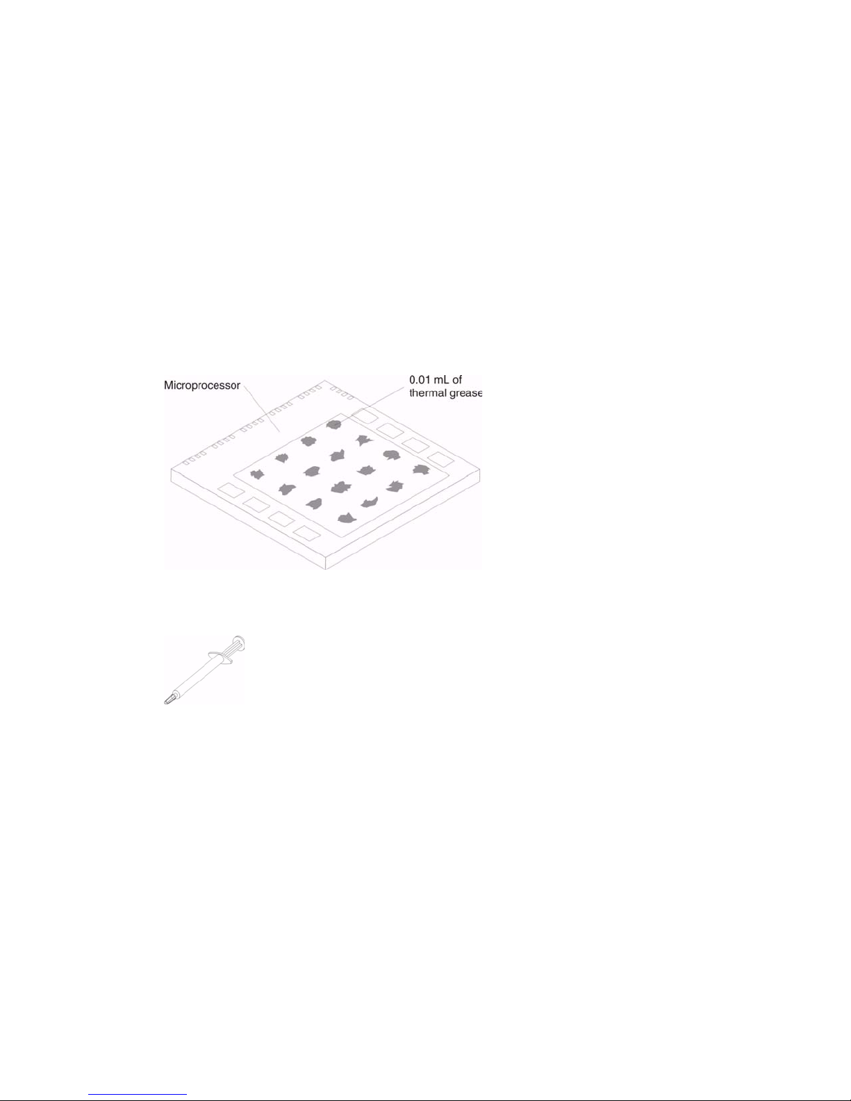
• Read “Installation guidelines” on page 27.
• Read the safety notices at “Electrical Safety” on page vi.
• Read “Handling electrostatic discharge-sensitive devices” on page vi
Complete the following steps to replace damaged or contaminated thermal grease on the
microprocessor and heat sink:
1. Place the heat sink on a clean work surface.
2. R emove the cleaning pad from its package and unfold it completely.
3. Use the cleaning pad to wipe the thermal grease from the bottom of the heat sink.
✏
NOTE
Be sure that all of the thermal grease is removed.
4. U se a clean area of the cleaning pad to wipe the thermal grease from the microprocessor; then,
dispose of the cleaning pad after all of the thermal grease is removed.
5. U se the thermal grease syringe to place 16 uniformly spaced dots of 0.01mL each on the top of
the microprocessor.
✏
NOTE
0.01mL is one tick mark on the syringe. If the grease is properly applied, approximately
half (0.22mL) of the grease will remain in the syringe.
6. Install the heat sink onto the microprocessor as described in “Installing an additional
microprocessor” on page 38
System board
When replacing the system board, you must either update the system with the latest firmware or
restore the pre-existing firmware that the customer provides on a diskette or CD image.
✏
NOTE
Service replaceable units 65
Page 80
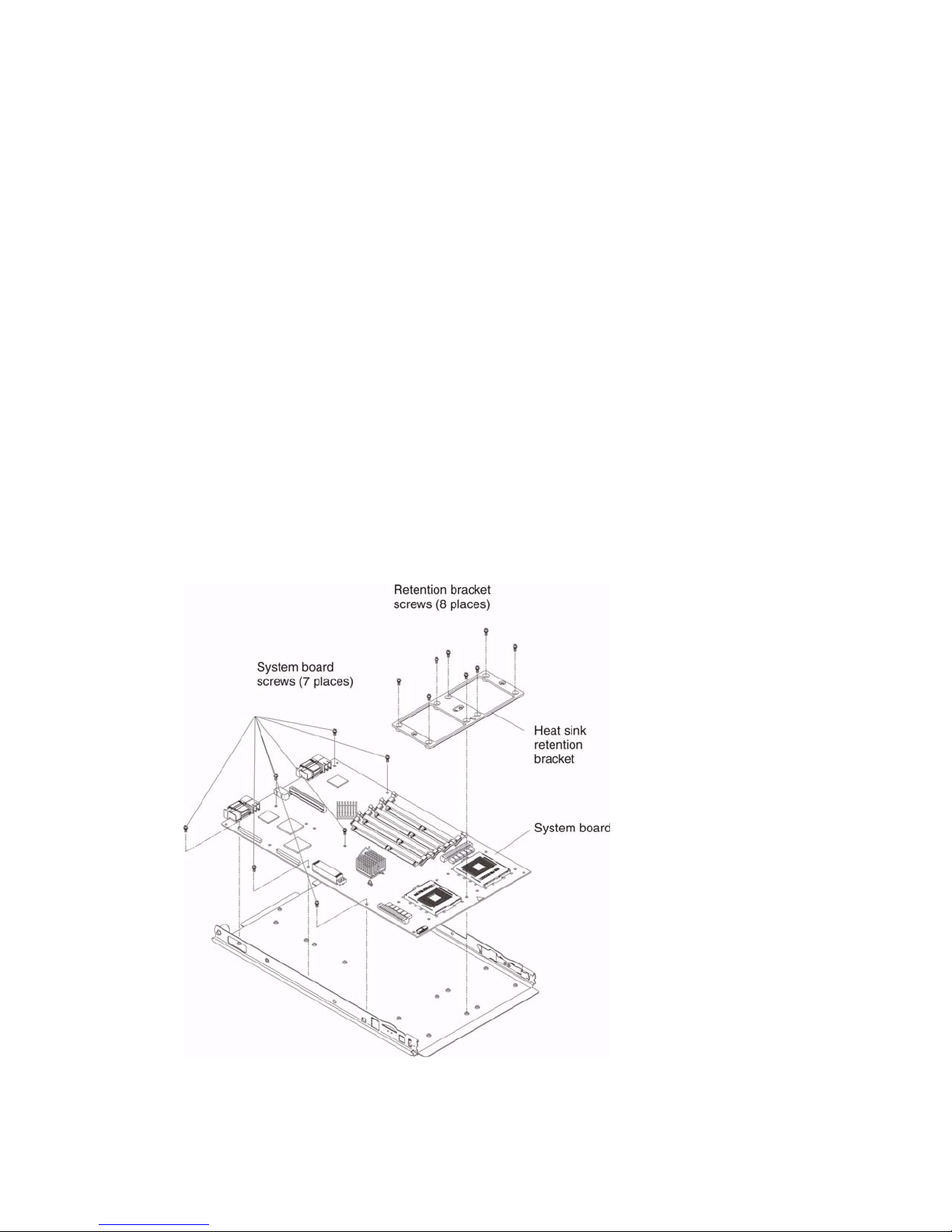
• Read “Installation guidelines” on page 27
• Read the safety notices at “Electrical Safety” on page vi
• Read “Handling electrostatic discharge-sensitive devices” on page vi
Complete the following steps to remove the system board:
1. Shut down the operating system and turn off the blade server (see “Turning off the blade server”
on page 5).
2. R emove the blade server from the SBCE chassis (see “Removing the blade server from the
SBCE unit” on page 33).
3. R emove the blade server cover (see “Opening the blade server cover” on page 33) or SCSI
storage expansion unit (see “Installing a SCSI storage expansion unit” on page 43).
4. R emove the blade server bezel assembly (see “Removing the blade server bezel assembly” on
page 35).
5. R emove all components (see the appropriate installation instructions and reverse the steps) and
place them on a static-protective surface for reinstallation.
Notes:
a. A microprocessor assembly ships with a new heat sink.
b. A system board does not ship with a heat sink. When replacing the system board and re-
installing an existing microprocessor, be sure to also re-install the heat sink (see “Thermal
grease” on page 64).
66 SBXL52: Hardware Maintenance Manual and Troubleshooting Guide
Page 81

6. Remove the eight scre ws that secure the heat sink retention brack et to the system board, and put
the screws and the module in a safe place.
Notes:
a. Note the alignment of the heat sink retention bracket (the arrow on the bracket aligns with
the arrow on the system board). You will need to align the bracket the same way when
reinstalling it.
b. One of the screws also helps secure the system board to the blade chassis.
7. R emove the other seven screws that secure the system board to the blade chassis, and put the
screws in a safe place.
8. Pull the system board carefully out of the blade chassis.
Reverse these steps to install the replacement system board.
✏
NOTE
T wo self -adhesiv e labels ship with the system board. Apply one on top of the existing ethernet
MAC address label located on the bottom of the blade chassis. The other label remains with
the owner.
Service replaceable units 67
Page 82

<This page intentionally left blank>
68 SBXL52: Hardware Maintenance Manual and Troubleshooting Guide
Page 83
9 Symptom-to-FRU index
This index supports the SBXL52 blade servers.
Notes:
1. Check the configuration before you replace a FRU. Configuration problems can cause false
errors and symptoms.
2. For Intel devices not supported by this index, refer to the manual for that device.
3. Always start with “General checkout” on page 19
The symptom-to-FRU index lists sympt oms, errors, and the pos sible causes. The most lik ely cause is
listed first. Use this symptom-to-FRU index to help you decide which FR Us to have availab le when
servicing the server.
The left-hand column of the tables in this index lists error codes or messages, and the right-hand
column lists one or more suggested actions or FRUs to replace.
NOTE
✏
In tables with more than two columns, multiple columns are required to describe the error
symptoms.
Take the action (or replace the FRU) suggested first in the list of the right-hand column, then try the
server again to see if the problem has been corrected before taking further action.
✏
NOTE
Reseat a suspected component or reconnect a cable before replacing the component.
The POST BIOS code displays POST error codes and messages on the screen.
Beep symptoms
Beep symptoms are short tones or a series of short tones separated by pauses (intervals without
sound). See the examples in the following table.
Beeps Description
1-2-3 • One beep
• A pause (or break)
• Two beeps
• A pause (or break)
• Three beeps
4 Four continuous beeps
One beep after successfully completing POST indicates the system is functioning properly.
69
Page 84

✏ NOTE
See “System” on page 104 to determine which components should be replaced by a field service
technician.
Beep/symptom FRU/action
1-1-2
(Microprocessor register test failed)
1-1-3
(CMOS write/read test failed)
1-1-4
(BIOS ROM checksum failed)
1-2-1
(Programmable Interval Timer
failed)
1-2-2
(DMA initialization failed)
1. Optional microprocessor (if installed)
2. Microprocessor
3. System board
1. Battery
2. System board
1. Flash BIOS.
2. DIMM.
3. System board.
• System board
• System board
1-2-3
(DMA page register write/read
failed)
1-2-4
(RAM refresh verification failed)
1-3-1
(first 64K RAM test failed)
1-3-2
(first 64K RAM parity test failed)
2-1-1
(Secondary DMA register failed)
2-1-2
(Primary DMA register failed)
2-1-3
(Primary interrupt mask register
failed)
2-1-4
(Secondary interrupt mask register
failed)
2-2-1
(Interrupt vector loading failed)
• System board
1. DIMM
2. System board
1. DIMM
2. System board
1. DIMM
2. System board
• System board
• System board
• System board
• System board
• System board
2-2-2
(Keyboard controller failed)
70 SBXL52: Hardware Maintenance Manual and Troubleshooting Guide
1. Keyboard
2. System board
3. Management module
Page 85

✏
NOTE
See “System” on page 104 to determine which components should be replaced by a field service
technician.
Beep/symptom FRU/action
2-2-3
(CMOS power failure and
checksum checks failed)
2-2-4
(CMOS configuration information
validation failed)
2-3-1
(Screen initialization failed)
2-3-2
(Screen memory failed)
2-3-3
(Screen retrace failed)
2-3-4
(Search for video ROM failed)
2-4-1
(Video failed; screen believed
operable)
3-1-1
(Timer tick interrupt failed)
3-1-2
(Interval timer channel 2 failed)
3-1-3
(RAM test failed above address
OFFFFH))
3-1-4
(Time-Of-Day clock failed)
1. Battery
2. System board
1. Battery
2. System board
• System board
• System board
• System board
• System board
• System board
• System board
• System board
1. DIMM
2. System board
1. Battery
2. System board
3-2-1
(Serial port failed)
3-2-2
(Parallel port failed)
3-2-3
(Math coprocessor test failed)
3-2-4
(Failure comparing CMOS memory
size against actual)
3-3-1
(Memory size mismatch occurred.)
Symptom-to-FRU index 71
• System board
• System board
1. Microprocessor
2. System board
1. DIMM
2. System board
3. Battery
1. Verify that both DIMMs in bank are of the same size, speed, type and
technology.
2. DIMM
3. System board
4. Battery
Page 86

NOTE
✏
See “System” on page 104 to determine which components should be replaced by a field service
technician.
Beep/symptom FRU/action
3-3-2
(Critical SMBUS error occurred)
3-3-3
(No operational memory in system)
✏ NOTE
In some memory
configurations, the 3-3-3
beep code might sound
during POST followed by a
blank display screen. If this
occurs and the Boot Fail
Count feature in the Start
Options of the
Configuration/Setup Utility is
set to Enabled (its default
setting), you must restart the
server three times to force
the system BIOS code to
reset the memory connector
or bank of connectors from
Disabled to Enabled.
Two short beeps
(Information only, the configuration
has changed)
Three short beeps 1. DIMM
One continuous beep 1. Microprocessor
Repeating short beeps 1. Keyboard
1. Power down blade server and reseat it in chassis.
2. DIMMs.
3. System board.
1. Install or reseat the memory modules, and then do a 3 boot reset.
(For more information on a 3 boot reset, see “Using the
Configuration/Setup Utility program” on page 11)
2. DIMMs.
3. System board.
1. Run Diagnostics.
2. Run the Configuration/Setup Utility program.
2. System board
2. Optional microprocessor (if installed)
3. System board
2. System board
72 SBXL52: Hardware Maintenance Manual and Troubleshooting Guide
Page 87
No-beep symptoms
✏ NOTE
See “System” on page 104 to determine which components should be replaced by a field service
technician.
No-beep symptom FRU/action
No beep and the system
operates correctly.
No beep and no video (System
error LED is OFF)
• System board
• See “Undetermined problems” on page 100.
No beep and no video (System
Attention LED is ON)
• See “Identifying problems using the light path diagnostics” on page 24
Diagnostic error codes
✏ NOTE
In the following error codes, if XXX is 000, 195, or 197, do not replace a FRU. The
description for these error codes are:
000 The test passed.
195 The Esc key was pressed to stop the test.
197 Warning; a hardware failure might not have occurred.
For all error codes, replace the FRU or take the action indicated.
✏
NOTE
See “System” on page 104 to determine which components should be replaced by a field service
technician.
Error code/symptom FRU/action
001-250-000
(Failed system board ECC)
001-250-001
(Failed processor board ECC)
001-292-000 (Core system: failed/CMOS
checksum failed)
001-XXX-000
(Failed core tests)
001-XXX-001
(Failed core tests)
005-XXX-000
(Failed video test)
Symptom-to-FRU index 73
• System board
• System board
• Load BIOS defaults and rerun test.
• System board
• System board
• System board
Page 88

✏
NOTE
See “System” on page 104 to determine which components should be replaced by a field service
technician.
Error code/symptom FRU/action
030-XXX-000
(Failed internal SCSI interface test)
035-XXX-099 1. No adapters were found.
075-XXX-000
(Failed power supply test)
089-XXX-001
(Failed microprocessor test)
089-XXX-002
(Failed opti onal microprocessor test)
165-060-000 (Service Processor: ASM
may be busy)
165-198-000 (Service Processor:
Aborted)
1. SCSI storage expansion unit
2. System board
2. If adapter is installed re-check connection.
• Power supply
1. Microprocessor 1
2. System board
1. Optional microprocessor 2
2. System board
1. Rerun the diagnostic test.
2. Fix other error conditions that may be keeping ASM busy. Refer to
the error log and diagnostic panel.
3. Power down blade server and reseat it in chassis.
4. System board.
1. Rerun the diagnostic test
2. Fix other error conditions that may be keeping ASM busy. Refer to
the error log and diagnostic panel.
3. Power down blade server and reseat it in chassis.
4. System board.
165-201-000 (Service Processor: Failed) 1. Power down blade server and reseat it in chassis.
2. System board.
165-330-000 (Service Processor: Failed) • Update to the latest ROM diagnostic level and retry.
165-342-000 (Service Processor: Failed) 1. Ensure latest firmware levels for ASM and BIOS are installed.
2. Power down blade server and reseat it in chassis.
3. System board.
166-198-000 System Management:
Aborted
(Unable to communicate with ASM. It may
be busy. Run the test again.)
166-201-001 System Management:
Failed (I2C bus error(s) See SERVPROC
and DIAGS entries in event log.)
166-201-002 System Management:
Failed (I2C bus error(s) See SERVPROC
and DIAGS entries in event log.)
1. Run the diagnostic test again.
2. Correct other error conditions and retry. These include other failed
system management tests and items logged in the System Error
Log of the management module.
3. Power down blade server and reseat it in chassis.
4. System board.
1. DIMMs
2. System board
1. Reseat I2C cable between the operator information card and
the system board.
2. Operator information card.
3. System board.
74 SBXL52: Hardware Maintenance Manual and Troubleshooting Guide
Page 89

✏
NOTE
See “System” on page 104 to determine which components should be replaced by a field service
technician.
Error code/symptom FRU/action
166-201-003 System Management:
Failed (I2C bus error(s) See SERVPROC
and DIAGS entries in event log.)
166-201-004 System Management:
Failed
(I2C bus error(s) See SERVPROC and
DIAGS entries in event log.)
166-201-005 System Management:
Failed
(I2C bus error(s) See SERVPROC and
DIAGS entries in event log.)
166-342-000 System Management:
Failed
(ASM adapter BIST indicate failed tests.)
166-400-000 System Management:
Failed (ISMP self test result failed tests: x
where x = Flash, RAM, or ROM.)
180-XXX-000 (Diagnostics LED failure) • Run diagnostics panel LED test for the failing LED.
180-XXX-001
(Failed front LED panel test)
180-XXX-002
(Failed diagnostics LED panel test)
1. I/O adapter
2. System board
1. SCSI storage expansion unit
2. System board
1. DIMMs
2. Microprocessors
3. System board
1. Ensure the latest firmware levels for Remote Supervisor
Adapter and BIOS are installed.
2. Power down blade server and reseat it in chassis.
3. Remote Supervisor Adapter.
1. Reflash or update firmware for ISMP.
2. System board.
1. Front bezel with customer interface card
2. System board
• System board
180-XXX-003
(Failed system board LED test)
180-XXX-005
(Failed SCSI backplane LED test)
201-XXX-0nn
(Failed memory test.)
201-XXX-999
(Multiple DIMM failure, see error text)
202-XXX-001
(Failed system cache test)
202-XXX-002
(Failed system cache test)
217-198-XXX
(Could not establish drive parameters)
• System board
1. SCSI storage expansion unit
2. System board
1. DIMM Location slots 1-4 where nn = DIMM location.
✏
NOTE
nn 1=DIMM 1; 2=DIMM 2; 3=DIMM 3; 4=DIMM 4.
2. System board.
1. See error text for failing DIMMs.
2. System board.
1. Microprocessor 1
2. System board
1. Microprocessor 2
2. System board
• SCSI storage expansion unit
Symptom-to-FRU index 75
Page 90

NOTE
✏
See “System” on page 104 to determine which components should be replaced by a field service
technician.
Error code/symptom FRU/action
217-XXX-000
(Failed hard disk drive test)
✏ NOTE
If RAID is configured, the hard disk
drive number refe rs to the RAI D
logical array.
217-XXX-001
(Failed hard disk test)
✏
NOTE
If RAID is configured, the hard disk
number refers to the RAID logical
array.
405-XXX-000
(Failed Ethernet test on controller on the
system board)
• Hard disk drive 1
• Hard disk drive 2
1. Verify that Ethernet is not disabled in BIOS.
2. System board.
POST error codes
In the following error codes, X can be any number or letter.
✏
NOTE
See “System” on page 104 to determine which components should be replaced by a field service
technician.
Error code/symptom FRU/acti on
062
(Three consecutive startup failures using
the default config u ration.)
1. Run the Configuration/Setup Utility program.
2. Battery.
3. System board.
4. Microprocessor.
101, 102
(System and processor error)
106
(System and processor error)
111
(Channel check error)
114
(Adapter read-only memory error)
76 SBXL52: Hardware Maintenance Manual and Troubleshooting Guide
• System board
• System board
1. Failing adapter
2. DIMM
3. System board
1. Failing adapter.
2. Run diagnostics.
Page 91

✏
NOTE
See “System” on page 104 to determine which components should be replaced by a field service
technician.
Error code/symptom FRU/acti on
151
(Real time clock error)
161
(Real time clock battery error)
162
(Device configuration error)
✏ NOTE
Be sure to load the default settings
and any additional desired
settings; then, save the
configuration.
163
(Real-time clock error)
164
(Memory configuration changed.)
165
(Service Processor failure)
184
(Power-on password damaged)
1. Run diagnostics.
2. Battery.
3. System board.
1. Run the Configuration/Setup Utility program.
2. Battery.
3. System board.
1. Run the Configuration/Setup Utility program.
✏
NOTE
If unable to enter Configuration/Setup Utility program, view
system event log in SBCE management module.
2. Battery.
3. Failing device.
4. System board.
1. Run the Configuration/Setup Utility program.
2. Battery.
3. System board.
1. Run the Configuration/Setup Utility program.
2. DIMM.
3. System board.
• System board
1. Run the Configuration/Setup Utility program.
2. System board.
185
(Drive startup sequence information
corrupted)
189
(An attempt was made to access the
server with invalid passwords)
201
(Memory test error.) If the server does
not have the latest le v el of BIOS installed,
update the BIOS to the latest level and
run the diagnostic program again.
229
(Cache error)
262
(DRAM parity configuration error)
Symptom-to-FRU index 77
1. Run the Configuration/Setup Utility program.
2. System board.
• Run the Configuration/Setup Utility program, and enter the
administrator password.
1. DIMM
2. System board
1. Microprocessor
2. Optional microprocessor (if installed)
1. Run the Configuration/Setup Utility program.
2. Battery.
3. System board.
Page 92

✏
NOTE
See “System” on page 104 to determine which components should be replaced by a field service
technician.
Error code/symptom FRU/acti on
289
(DIMM disabled by POST or user)
301
(Keyboard or keyboard controller error)
303
(Keyboard controller error)
602
(Invalid diskette boot record)
604
(Diskette drive error)
605
(Unlock failure)
662
(Diskette drive configuration error)
1. Run the Configuration/Setup Utility program, if the DIMM was
disabled by the user.
2. Disabled DIMM, if not disabled by user.
3. System board
1. Keyboard
2. System board
• System board
1. Diskette
2. Diskette drive
3. Cable
4. System board
1. Run the Configuration/Setup Utility program and diagnostics.
2. Diskette drive.
3. Drive cable.
4. System board.
1. Diskette drive
2. Drive cable
3. System board
1. Run the Configuration/Setup Utility program and diagnostics.
2. Diskette drive.
3. Drive cable.
4. System board.
762
(Coprocessor configuration error)
962
(Parallel port configuration error)
11XX
(System board serial port 1 or 2 error)
1162
(Serial port configuration conflicts)
1. Run the Configuration/Setup Utility program.
2. Battery.
3. Microprocessor.
1. Run the Configuration/Setup Utility program and verify that the
parallel-port setting is correct.
2. System board.
1. Disconnect the external cable on the serial port.
2. Run the Configuration/Setup Utility program.
3. System board.
1. Run the Configuration/Setup Utility program and ensure that the
IRQ and I/O port assignments needed by the serial port are
available.
2. If all interrupts are being used by adapters, remove an adapter or
force other adapters to share an interrupt.
78 SBXL52: Hardware Maintenance Manual and Troubleshooting Guide
Page 93

✏
NOTE
See “System” on page 104 to determine which components should be replaced by a field service
technician.
Error code/symptom FRU/acti on
1301
(I2C cable to operator information panel
not found)
1302
(I2C cable from system board to poweron and reset switches not found)
1303
(I2C cable from system board to power
backplane not found)
1304
(I2C cable to diagnostic LED board not
found)
1762
(Hard disk configuration error)
178X
(Fixed disk error)
1800
(No more hardware interrupt available for
PCI adapter)
1. Cable
2. Operator information card
3. Power switch assembly
4. System board
1. Cable
2. Power switch assembly
3. System board
1. Cable
2. Power supply
3. System board
1. Power switch assembly
2. System board
1. Hard disk drive.
2. Hard disk drive cables.
3. Run the Configuration/Setup Utility program.
4. SCSI storage expansion unit.
5. System board.
1. Hard disk drive cables.
2. Run diagnostics.
3. Hard disk drive.
4. System board.
1. Run Configuration/Setup to verify that the interrupt resource
settings are correct.
2. Failing adapter (if installed).
3. System board.
1962
(Drive does not contain a valid boot
sector)
2400
(Video controller test failure)
Symptom-to-FRU index 79
1. Verify that a startable operating system is installed.
2. Run diagnostics.
3. Hard disk drive.
4. SCSI storage expansion unit.
5. System board.
1. Verify that the keyboard/mouse/video select button LED on the
front of the blade server is on, indicating that the blade server is
connected to the shared SBCE monitor.
2. Verify that the monitor is connected correctly to the SBCE unit.
3. Video adapter (if installed).
4. System board.
Page 94

✏
NOTE
See “System” on page 104 to determine which components should be replaced by a field service
technician.
Error code/symptom FRU/acti on
2462
(Video memory configuration error)
5962
(IDE CD-ROM drive configuration error)
8603
(Pointing-device error)
0001200
(Machine check architecture error)
00012000
(Microprocessor machine check)
00019501
(Microprocessor 1 is not functioning check VRM and microprocessor LEDs)
00019502
(Microprocessor 2 is not functioning –
check VRM and microprocessor LEDs)
00019701
(Microprocessor 1 failed)
00019702
(Microprocessor 2 failed)
1. Verify that the keyboard/mouse/video select button LED on the
front of the blade server is on, indicating that the blade server is
connected to the shared SBCE monitor.
2. Verify that the monitor is connected correctly to the SBCE unit.
3. Video adapter (if installed).
4. System board.
1. Run the Configuration/Setup Utility program.
2. CD-ROM drive.
3. CD-ROM power cable.
4. IDE cable.
5. System board.
6. Battery.
1. Pointing device
2. System board
1. Microprocessor 1
2. Optional microprocessor 2
3. System board
1. Microprocessor
2. System board
1. Microprocessor 1
2. System board
1. Microprocessor 2
2. System board
1. Microprocessor 1
2. System board
1. Microprocessor 2
2. System board
00151200
(microprocessor machine check)
00180200
(No more I/O space available for
adapter)
01295085
(ECC checking hardware test error)
80 SBXL52: Hardware Maintenance Manual and Troubleshooting Guide
1. Run the Configuration/Setup Utility program.
2. Microprocessor (check error LED for failing microprocessor).
3. System board.
1. Run the Configuration/Setup Utility program.
2. Failing adapter.
3. System board.
1. System board
2. Microprocessor
Page 95

✏
NOTE
See “System” on page 104 to determine which components should be replaced by a field service
technician.
Error code/symptom FRU/acti on
01298001
(System BIOS installed on this server
does not support level of processor)
01298002
(System BIOS installed on this server
does not support level of processor)
01298101
(System BIOS installed on this server
does not support level of processor)
01298102
(System BIOS installed on this server
does not support level of processor)
01298200
(Microprocessor speed mismatch)
I9990301
(Hard disk sector error)
I9990305
(Hard disk sector error, no operating
system installed)
I9990650
(AC power has been restored)
1. Ensure all microprocessors have the same cache size.
2. Microprocessor 1.
1. Ensure all microprocessors have the same cache size.
2. Microprocessor 2.
1. Ensure all microprocessors have the same cache size.
2. Microprocessor 1.
1. Ensure all microprocessors have the same cache size.
2. Microprocessor 2.
1. Ensure all microprocessors are the same speed.
2. Microprocessor.
1. Hard disk drive
2. SCSI backplane
3. Cable
4. System board
• Install operating system to hard disk.
1. Check cable.
2. Check for interruption of power.
3. Power cable.
Light path diagnostics
Lit blade-error
LED Cause Action
None An error has occurred and cannot be isolated,
or the service processor has failed.
Symptom-to-FRU index 81
• An error has occurred that is not
represented by a Light Path Diagnostics
LED. Check the system error log for more
information about the error.
Page 96

Lit blade-error
LED Cause Action
DIMM x error A memory error occurred. 1. Reseat the DIMM indicated by the lit DIMM
failure LED.
2. Replace the DIMM.
✏
NOTE
Multiple DIMM LEDs do not necessarily
indicate multiple DIMM failures. If more
than one DIMM LED is on,
reseat/replace one DIMM at a time until
error goes away. Refer to the SBCE
management module system error log
for further isolation.
Processor x
error
The microprocessor has failed. 1. Verify that the microprocessor indicated by
the lit LED is installed correctly. (See
“Installing an additional microprocessor” on
page 38 for installation instructions).
2. Replace the microprocessor.
Temperature
error
System board
error
IDE bus x error The IDE bus indicated by the error LED has
NMI error The system board has failed. 1. Replace the blade server cover, reinsert
Processor
mismatch
The system temperature has exceeded a
threshold level.
The system board has failed 1. Replace the blade server cover, reinsert
failed.
The processors do not match. • Verify that microprocessors 1 and 2 have
1. Check to see if a blower on the SBCE unit
has failed. If it has, replace the fan.
2. Make sure the room temperature is not too
high. (See “Features and specifications” on
page 2 for temperature information.)
the blade server in the SBCE unit, and
then restart the server .
2. Replace the system board.
1. Reseat/replace the hard disk drive on IDE
bus x.
2. Replace the system board.
the blade server in the SBCE unit, and
then restart the blade server.
2. Check the system error log for information
about the error.
If the problem remains, replace the system
board.
the same cache size and type and the
same clock speed. Internal and external
clock frequencies must be identical; also
see “Error symptoms” on page 83.
82 SBXL52: Hardware Maintenance Manual and Troubleshooting Guide
Page 97

IDE RAID
✏ NOTE
See “System” on page 104 to determine which components should be replaced by a field service
technician.
Error symptom FRU /a ction
Drives are not detected 1. Verify that drives are installed correctly:
a. Cables should be of type Ultra A TA-100 or A TA-133 and should be installed
correctly.
b. Power cables to drives should be connected properly.
2. Cables.
3. Drive.
System hangs when
MegaRAID IDEal Software
CSB6 RAID adapter ROM
scans the IDE channels
BIOS reports that a mirrored
array is in degraded mode
1. Verify that drives are installed correctly:
a. Cables should be of type Ultra A TA-100 or A TA-133 and should be installed
correctly.
b. Power cables to drives should be connected properly.
2. Cables.
3. Drive.
1. Verify that all physical drives are:
a. Installed correctly
b. Powered on
2. Reconnect, replace, or rebuild any failed drive.
One of the hard disk drives in
a mirrored array has failed
"NO ROM BASIC SYSTEM
HALTED" message displays
during startup (There are no
active partitions)
Operating system does not
boot
1. Verify that drives are installed correctly.
2. Replace drive with another drive of the same capacity.
1. Verify that drives are installed correctly.
2. Run FDISK to set active partition.
1. Check system BIOS configuration for PCI interrupt assignments and
verify that some interrupts are assigned for PCI.
2. Verify that the boot device in system BIOS setup (CMOS setup) is selected
correctly.
Error symptoms
You can use the error symptom table to find solutions to problems that have definite symptoms.
If you cannot find the problem in the error symptom charts, go to “Starting the diagnostic programs”
on page 22 to test the server.
If you have just added ne w softw are or a new op tion and your serv er is not working, do the following
before using the error symptom charts:
• Remove the software or device that you just added.
• Run the diagnostic tests to determine if your server is running correctly.
Symptom-to-FRU index 83
Page 98

• Reinstall the new software or new device.
In the following table, if the entry in the FRU/action column is a suggested action, perform that
action; if it is the name of a component, reseat the component and replace it if necessary. The most
likely cause of the symptom is listed first.
✏ NOTE
See “System” on page 104 to determine which components should be replaced by a field service
technician.
CD-ROM drive problems
Symptom FRU/action
CD-ROM drive is not
recognized.
CD is not working properly. 1. Clean the CD.
1. Verify that:
• All cables and jumpers are installed correctly.
• The correct device driver is installed for the CD-ROM drive.
2. Run CD-ROM drive diagnostics.
3. CD-ROM drive.
2. Run CD-ROM drive diagnostics.
3. CD-ROM drive.
CD-ROM drive tray is not
working. (The computer must
be turned on.)
CD-ROM drive is not
recognized after being
switched back to blade server
running Windows 2000
Advanced Server with SP3
applied. (When the CD-ROM
drive is owned by blade server
x, is switched to another blade
server, then is switched back
to blade server x, the operating
system in blade server x no
longer recognizes the CDROM drive. This happens
when you have not safely
stopped the drives before
switching ownership of the CDROM drive, diskette drive, and
USB port (media tray).
1. Insert the end of a straightened paper clip into the manual tray-release
opening.
2. Run CD-ROM drive diagnostics.
3. CD-ROM drive.
NOTE
✏
Because the SBCE unit uses a USB bus to communicate with the media tray
devices, switching o wnership of the media tray to another blade server is the
same as unplugging a USB device.
• Before switching ownership of the CD-ROM drive (media tray) to another blade
server, safely stop the media tray devices on the blade server that currently
owns the media tray, as follows:
1. Double-click the Unplug or Eject Hardware icon in the Windows taskbar at
the bottom right of the screen.
2. Select USB Floppy and click Stop.
3. Select USB Mass Storage Device and click Stop.
4. Click Close.
You can now saf ely switch ownership of the media tray to another blade server.
84 SBXL52: Hardware Maintenance Manual and Troubleshooting Guide
Page 99

✏ NOTE
See “System” on page 104 to determine which components should be replaced by a field service
technician.
Diskette drive problems
Symptom FRU/action
Diskette drive activity LED
stays on, or the system
bypasses the diskette drive.
✏
NOTE
See “System” on page 104 to determine which components should be replaced by a field service
technician.
Expansion enclosure problems
1. If there is a diskette in the drive, verify that:
• The diskette is inserted correctly in the drive.
• The diskette is good and not damaged. (Try another diskette if you have
one.)
— The drive light comes on (one-second flash) when the diskette is
inserted.
• The diskette contains the necessary files to start the computer.
• The diskette drive is enabled in the Configuration/Setup utility program.
• The software program is working properly.
• The cable is installed correctly (in the proper orientation).
2. To prevent diskette drive read/write errors, be sure the distance between
monitors and diskette drives is at least 76 mm (3 in.).
3. Cable.
4. Run diskette drive diagnostics.
5. Diskette drive.
6. Media tray card.
Symptom FRU/action
The SCSI storage expansion
unit used to work but does not
work now.
1. Verify that the enclosure is installed correctly.
2. For more information, see your SCSI storage expansion unit documentation.
NOTE
✏
See “System” on page 104 to determine which components should be replaced by a field service
technician.
Hard disk drive problems
Symptom FRU/action
Not all drives are recognized
by the hard disk drive
diagnostic test (Fixed Disk
test).
1. Remove the first drive not recognized and try the hard disk drive
diagnostic test again.
2. If the remaining drives are recognized, replace the drive you removed with a
new one.
Symptom-to-FRU index 85
Page 100

NOTE
✏
See “System” on page 104 to determine which components should be replaced by a field service
technician.
Hard disk drive problems
Symptom FRU/action
System stops responding
during hard disk drive
diagnostic test.
1. Remove the hard disk drive being tested when the computer stopped
responding and try the diagnostic test again.
2. If the hard disk drive diagnostic test runs successfully, replace the drive you
removed with a new one.
NOTE
✏
See “System” on page 104 to determine which components should be replaced by a field service
technician.
General problems
Symptom FRU/action
Problems such as broken
cover locks or indicator LEDs
not working
• Broken CRU/FRU
NOTE
✏
See “System” on page 104 to determine which components should be replaced by a field service
technician.
Intermittent problems
Symptom FRU/action
A problem occurs only
occasionally and is difficult to
detect.
• Verify that:
— When the computer is turned on, air is flowing from the rear of the computer
at the blower grill. If there is no airflow, the blower is not working. This
causes the computer to overheat and shut down.
— Ensure that the SCSI bus and devices are configured correctly.
86 SBXL52: Hardware Maintenance Manual and Troubleshooting Guide
 Loading...