

Page 1

Intel® Server Compute Blade SBXD132
Installation and User’s Guide
A Guide for Technically Qualified Assemblers of Intel® Identified Subassemblies/
Products
Intel Order Number D64326-002
Page 2

Disclaimer
Information in this document is provided in connection with Intel® products. No license, express or implied, by
estoppel or otherwise, to any intellectual property rights is granted by this document. Except as provided in Intel's
Terms and Conditions of Sale for such products, Intel assumes no liability whatsoever, and Intel disclaims any
express or implied warranty, relating to sale and/or use of Intel® products including liability or warranties relating to
fitness for a particular purpose, merchantability, or infringement of any patent, copyright or other intellectual property
right. Intel products are not designed, intended or authorized for use in any medical, life saving, or life sustaining
applications or for any other application in which the failure of the Intel product could create a situation where
personal injury or death may occur. Intel may make changes to specifications and product descriptions at any time,
without notice.
Intel® server boards contain a number of high-density VLSI and power delivery components that need adequate
airflow for cooling. Intel's own chassis are designed and tested to meet the intended thermal requirements of these
components when the fully integrated system is used together. It is the responsibility of the system integrator that
chooses not to use Intel developed server building blocks to consult vendor datasheets and operating parameters to
determine the amount of airflow required for their specific application and environmental conditions. Intel
Corporation can not be held responsible if components fail or the server board does not operate correctly when used
outside any of their published operating or non-operating limits.
Intel, Intel Pentium, and Intel Xeon are trademarks or registered trademarks of Intel Corporation or its subsidiaries in
the United States and other countries.
* Other names and brands may be claimed as the property of others.
Copyright © 2006-2007, Intel Corporation. All Rights Reserved
Page 3

Contents
Safety Information .................................................................................................... vii
Important Safety Instructions ............................................................................................... vii
Wichtige Sicherheitshinweise .............................................................................................. vii
Consignes de sécurité ......................................................................................................... vii
Instrucciones de seguridad importantes .............................................................................. vii
Warnings.............................................................................................................................. viii
Introduction .................................................................................................................1
Related Documentation .........................................................................................................2
The Resource CD ..................................................................................................................3
Hardware and Software Requirements ..................................................................................3
Notices and Statements Used in this Document ...................................................................3
Features and Specifications ..................................................................................................4
What Your Blade Server Offers ............................................................................................. 5
Reliability, Availability, and Serviceability Features ...............................................................6
Major Components of the Blade Server................................................................................. 8
Power, Controls, Jumpers, Switches, and Indicators ............................................. 9
Turning on the Blade Server ..................................................................................................9
Turning off the Blade Server ..................................................................................................9
Understanding the Control Panel and LEDs ........................................................................10
Blade Server Connectors .....................................................................................................12
Installing Options .....................................................................................................15
Installation Guidelines ..........................................................................................................15
System Reliability Guidelines ................................................................................................... 15
Handling Static-sensitive Devices ............................................................................................. 16
Removing the Blade Server from the Intel® Blade Server Chassis SBCE ..........................16
Opening the Blade Server Cover .........................................................................................17
Removing an Expansion Unit ..............................................................................................18
Removing the Blade Server Bezel Assembly ......................................................................19
Installing a SAS Hard Disk Drive ......................................................................................... 20
Removing a SAS Hard Disk Drive .......................................................................................21
Installing Memory Modules ..................................................................................................22
Installing an Additional Microprocessor ...............................................................................24
Installing an I/O-expansion Card .........................................................................................28
Installing a Small-form-factor Expansion Card ......................................................................... 29
Installing a Standard-form-factor Expansion Card .................................................................... 30
Installing an Expansion Unit ................................................................................................31
Completing the Installation ..................................................................................................32
Installing the Blade Server Bezel Assembly ............................................................................. 33
Intel® Server Compute Blade SBXD132 Installation and User’s Guide iii
Page 4

Closing the Blade Server Cover ............................................................................................... 34
Installing the Blade Server in an Intel
Updating the Blade Server Configuration ................................................................................. 36
®
Blade Server Chassis SBCE ....................................... 35
Input/output Connectors and Devices ................................................................................. 36
Memory and I/O Expansion for the Intel® Server Compute Blade SBXD132 .......37
Intel® Blade Storage Expansion Module for the Intel® Server Compute Blade
SBXD132 ....................................................................................................................39
Installation Guidelines ......................................................................................................... 39
System Reliability Considerations ............................................................................................ 40
Handling Static-sensitive Devices ............................................................................................ 40
Notices and Statements used in this Document.................................................................. 41
Installing the Expansion Unit ............................................................................................... 41
Installing the Expansion Unit Cover .................................................................................... 43
Removing the Expansion Unit Cover .................................................................................. 44
Installing a ServeRAID SAS Controller ............................................................................... 45
Installing an I/O-expansion Card ......................................................................................... 47
Installing a Hot-swap SAS Hard Disk Drive......................................................................... 50
Completing the Installation .................................................................................................. 51
Configuring the Expansion Unit RAID Array........................................................................ 52
Using the Adaptec RAID Configuration Utility Program ............................................................ 52
Using the ServeRAID Manager Program ................................................................................. 53
Light Path Diagnostics* ....................................................................................................... 53
Configuring the Blade Server ..................................................................................57
Using the Configuration/Setup Utility program .................................................................... 57
Configuration/Setup Utility Menu Choices ................................................................................ 58
Using Passwords ...................................................................................................................... 61
Using the PXE Boot Agent Utility Program .......................................................................... 61
Firmware Updates ...............................................................................................................61
Configuring the Gigabit Ethernet Controllers ....................................................................... 62
Blade Server Ethernet Controller Enumeration ................................................................... 62
Configuring a RAID Array .................................................................................................... 63
Using the LSI Logic Configuration Utility Program .............................................................. 63
Starting the LSI Logic Configuration Utility program ................................................................. 64
Installing the Operating System ..............................................................................65
Solving Problems ......................................................................................................67
Diagnostic Tools Overview .................................................................................................. 67
A Warranty ................................................................................................................69
Limited Warranty for Intel® Chassis Subassembly Products .............................................. 69
Extent of Limited Warranty .................................................................................................. 69
Warranty Limitations and Exclusions .................................................................................. 70
Limitations of Liability ............................................................................................................... 70
iv Intel® Server Compute Blade SBXD132 Installation and User’s Guide
Page 5

How to Obtain Warranty Service .............................................................................................. 70
Telephone Support ................................................................................................................... 71
Returning a Defective Product ..................................................................................................71
B Regulatory and Compliance Information ........................................................... 73
Product Regulatory Compliance ..........................................................................................73
Product Safety Compliance ......................................................................................................73
Product EMC Compliance - Class A Compliance ..................................................................... 74
Certifications / Registrations / Declarations .............................................................................. 74
Product Regulatory Compliance Markings ............................................................................... 75
Electromagnetic Compatibility Notices ................................................................................76
FCC Verification Statement (USA) ........................................................................................... 76
Industry Canada (ICES-003) .................................................................................................... 77
Europe (CE Declaration of Conformity) .................................................................................... 77
VCCI (Japan) ............................................................................................................................ 77
BSMI (Taiwan) .......................................................................................................................... 77
Korean Compliance (RRL) ........................................................................................................78
Restriction of Hazardous Substances (RoHS) Compliance .................................................78
End of Life / Product Recycling ............................................................................................78
C Getting Help ..........................................................................................................79
World Wide Web ..................................................................................................................79
Telephone ............................................................................................................................79
U.S. and Canada ...................................................................................................................... 79
Europe ...................................................................................................................................... 79
In Asia-Pacific region ................................................................................................................ 80
Japan ...................................................................................................................................... 80
Latin America ............................................................................................................................ 80
D Safety Information ...............................................................................................83
English .................................................................................................................................83
Server Safety Information ......................................................................................................... 83
Safety Warnings and Cautions ................................................................................................. 83
Intended Application Uses ........................................................................................................ 84
Site Selection ............................................................................................................................ 84
Equipment Handling Practices .................................................................................................. 84
Power and Electrical Warnings ................................................................................................. 84
System Access Warnings .........................................................................................................85
Rack Mount Warnings .............................................................................................................. 86
Electrostatic Discharge (ESD) ..................................................................................................86
Other Hazards .......................................................................................................................... 87
Deutsch................................................................................................................................ 88
Sicherheitshinweise für den Server .......................................................................................... 88
Sicherheitshinweise und Vorsichtsmaßnahmen ....................................................................... 88
Zielbenutzer der Anwendung .................................................................................................... 89
Standortauswahl ....................................................................................................................... 89
Handhabung von Geräten ........................................................................................................ 89
Intel® Server Compute Blade SBXD132 Installation and User’s Guide v
Page 6

Warnhinweise für den Systemzugang ...................................................................................... 91
Elektrostatische Entladungen (ESD) ........................................................................................ 92
Andere Gefahren ...................................................................................................................... 93
Français ............................................................................................................................... 94
Consignes de sécurité sur le serveur ....................................................................................... 94
Sécurité: avertissements et mises en garde ............................................................................. 94
Domaines d’utilisation prévus ................................................................................................... 95
Sélection d’un emplacement .................................................................................................... 95
Pratiques de manipulation de l’équipement .............................................................................. 95
Décharges électrostatiques (ESD) ........................................................................................... 98
Autres risques ........................................................................................................................... 99
Español ............................................................................................................................. 100
Información de seguridad del servidor ................................................................................... 100
Advertencias y precauciones sobre seguridad ....................................................................... 100
Aplicaciones y usos previstos ................................................................................................. 101
Selección de la ubicación ....................................................................................................... 101
Manipulación del equipo ......................................................................................................... 101
Advertencias el acceso al sistema ......................................................................................... 103
Descarga electrostática (ESD) ............................................................................................... 104
E Installation/Assembly Safety Instructions .......................................................111
English ............................................................................................................................... 111
Deutsch ............................................................................................................................. 113
Français ............................................................................................................................. 116
Español ............................................................................................................................. 118
Italiano ............................................................................................................................... 120
vi Intel® Server Compute Blade SBXD132 Installation and User’s Guide
Page 7
Safety Information
Important Safety Instructions
Read all caution and safety statements in this document before performing any of the
instructions. See also Intel® Server Boards and Server Chassis Safety Information on the
®
Server Deployment Toolkit CD and/or at http://support.intel.com/support/
Intel
motherboards/server/sb/cs-010770.htm.
Wichtige Sicherheitshinweise
Lesen Sie zunächst sämtliche Warnund Sicherheitshinweise in diesem Dokument, bevor
Sie eine der Anweisungen ausführen. Beachten Sie hierzu auch die Sicherheitshinweise zu
Intel-Serverplatinen und Servergehäusen auf der Intel
oder unter http://support.intel.com/support/motherboards/server/sb/cs-010770.htm.
Consignes de sécurité
®
Server Deployment Toolkit CD
Lisez attention toutes les consignes de sécurité et les mises en garde indiquées dans ce
document avant de suivre toute instruction. Consultez Intel Server Boards and Server
Chassis Safety Information sur le Intel
vous sur le site http://support.intel.com/support/motherboards/server/sb/cs-010770.htm.
®
Server Deployment Toolkit CD ou bien rendez-
Instrucciones de seguridad importantes
Lea todas las declaraciones de seguridad y precaución de este documento antes de realizar
重要安全指导
cualquiera de las instrucciones. Vea Intel Server Boards and Server Chassis Safety
Information en el Intel
support/motherboards/server/sb/cs-010770.htm.
®
Server Deployment Toolkit CD y/o en http://support.intel.com/
Intel® Server Compute Blade SBXD132 Installation and User’s Guide vii
Page 8

Warnings
These warnings and cautions apply whenever you remove the blade server enclosure
cover to access components inside the system. Only a technically qualified person should
maintain or configure the blade system.
Heed safety instructions: Before working with your server product, whether you are
using this guide or any other resource as a reference, pay close attention to the safety
instructions. You must adhere to the assembly instructions in this guide to ensure and
maintain compliance with existing product certifications and approvals. Use only the
described, regulated components specified in this guide. Use of other products /
components will void the UL listing and other regulatory approvals of the product and
will most likely result in noncompliance with product regulations in the region(s) in which
the product is sold.
System power on/off: The power button DOES NOT turn off the system AC power. To
remove power from the blade system, you must unplug the AC power cord from the wall
outlet or the chassis. Make sure the AC power cord is unplugged before you open the
chassis, add, or remove any components.
Hazardous conditions, devices and cables: Hazardous electrical conditions may be
present on power, telephone, and communication cables. Turn off the blade system and
disconnect the power cord, telecommunications systems, networks, and modems attached
to the blade system before opening it. Otherwise, personal injury or equipment damage
can result.
Electrostatic discharge (ESD) and ESD protection: ESD can damage disk drives,
boards, and other parts. We recommend that you perform all procedures in this document
only at an ESD workstation. If one is not available, provide some ESD protection by
wearing an anti-static wrist strap attached to chassis ground (any unpainted metal surface)
on your blade system when handling parts.
ESD and handling electronic devices: Always handle electronic devices carefully. They
can be extremely sensitive to ESD. Do not touch the connector contacts.
Installing or removing jumpers: A jumper is a small plastic encased conductor that slips
over two jumper pins. Some jumpers have a small tab on top that you can grip with your
fingertips or with a pair of fine needle nosed pliers. If your jumpers do not have such a
tab, take care when using needle nosed pliers to remove or install a jumper; grip the
narrow sides of the jumper with the pliers, never the wide sides. Gripping the wide sides
can damage the contacts inside the jumper, causing intermittent problems with the
function controlled by that jumper. Take care to grip with, but not squeeze, the pliers or
other tool you use to remove a jumper, or you may bend or break the pins on the board.
Reinstalling enclosure cover: To protect internal components and for proper cooling and
airflow, the blade server cannot be inserted into the SBCE unit with the blade enclosure
cover removed. Operating it without the enclosure cover in place can damage system
parts.
viii Intel® Server Compute Blade SBXD132 Installation and User’s Guide
Page 9

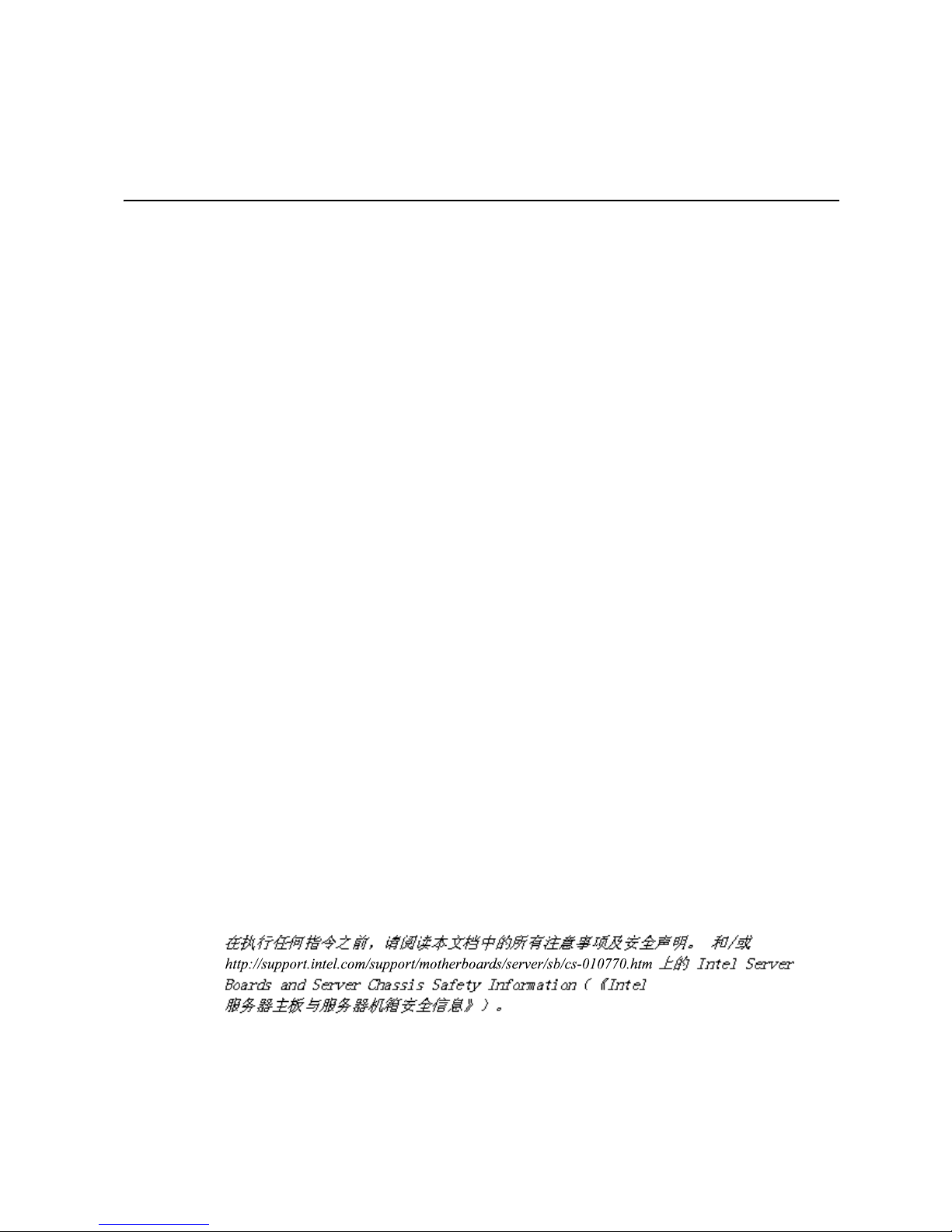
1 Introduction
The Intel® Server Compute Blade SBXD132 is compatible with the Intel® Blade Server
Chassis SBCE. This high-density, high-performance blade server is ideally suited for
networking environments that require superior microprocessor performance, efficient
memory management, flexibility, and reliable data storage.
This Installation and User’s Guide provides information about:
• Setting up the blade server
• Starting and configuring the blade server
• Installing hardware options
• Installing the operating system
• Performing basic troubleshooting of the blade server
Packaged with this document are software CDs that help you to configure hardware,
install device drivers, and install the operating system. To download the latest device
drivers, go to http://support.intel.com/support/.
The blade server comes with a limited warranty. For information about the terms of the
warranty and getting service and assistance, see Appendix A, “Warranty” on page 69. You
can obtain up-to-date information about the blade server at http://support.intel.com/
support/.
If firmware and documentation updates are available, you can download them from http://
support.intel.com/support/. The blade server might have features that are not described in
the documentation that comes with the blade server, and the documentation might be
updated occasionally to include information about those features, or technical updates
might be available to provide additional information that is not included in the blade
server documentation. To check for updates, go to http://support.intel.com/support/. For
firmware and documentation updates, under Download Center, type SBXD132 and
click Search.
Intel® Server Compute Blade SBXD132 Installation and User’s Guide 1
Page 10
Note: Changes are made periodically to the Intel Web site. Procedures for locating firmware
and documentation might change from what is described in this document.
Note: The illustrations in this document might differ slightly from the hardware.
Release
levers
Release
button
Related Documentation
This Installation and User’s Guide contains general information about the blade server,
including how to install supported options and how to configure the blade server. The
following documentation also comes with the blade server:
• Hardware Maintenance and Troubleshooting Guide
This document is in Portable Document Format (PDF) on the Resource CD. It
contains information to help you solve problems yourself, and it contains information
for service technicians.
• Safety Information
This document is in PDF format on the Resource CD. It contains translated caution
and danger statements. Each caution and danger statement that appears in the
documentation has a number that you can use to locate the corresponding statement in
your language in the Safety Information document.
Depending on your blade server product, additional documents might be included on the
Resource CD.
AF000639
2 Intel® Server Compute Blade SBXD132 Installation and User’s Guide
Page 11

The blade server might have features that are not described in the documentation that
comes with the server. The documentation might be updated occasionally to include
information about those features, or technical updates might be available to provide
additional information that is not included in the blade server documentation. The most
recent versions of all blade server documentation are at http://support.intel.com/support/.
In addition to the documentation in this library, be sure to review the Intel
Chassis SBCE Installation and User’s Guide for information to help you prepare for
system installation and configuration. This document is available at http://
support.intel.com/support/.
The Resource CD
You can run the Resource CD on any personal computer that meets the hardware and
software requirements.
The Resource CD contains documentation for your blade server in PDF format.
Hardware and Software Requirements
The Resource CD requires the following minimum hardware and software:
• Microsoft
Hat Linux.
®
Windows® NT 4.0 (with Service Pack 3 or later), Windows 2000, or Red
®
Blade Server
• 100-MHz microprocessor.
• 32 MB of RAM.
• Adobe Acrobat Reader 3.0 (or later) or xpdf, which comes with Linux operating
systems. Acrobat Reader software is included on the Resource CD.
Notices and Statements Used in this Document
The following notices and statements are used in this document:
• Note: These notices provide important tips, guidance, or advice.
• Important: These notices provide information or advice that might help you avoid
inconvenient or problem situations.
• Attention: These notices indicate possible damage to programs, devices, or data. An
attention notice is placed just before the instruction or situation in which damage
could occur.
• Caution: These statements indicate situations that can be potentially hazardous to
you. A caution statement is placed just before the description of a potentially
hazardous procedure step or situation.
• Danger: These statements indicate situations that can be potentially lethal or
extremely hazardous to you. A danger statement is placed just before the description
of a potentially lethal or extremely hazardous procedure step or situation.
Intel® Server Compute Blade SBXD132 Installation and User’s Guide 3
Page 12

Features and Specifications
The following table provides a summary of the features and specifications of the blade
server.
Notes:
• Power, cooling, removable-media drives, external ports, and advanced system
management are provided by the SBCE unit.
• The operating system in the blade server must provide USB support for the blade
server to recognize and use the removable-media drives and front-panel USB
ports.The SBCE unit uses USB for internal communications with these devices.
Microprocessor:
Supports up to two dual-core/quad-
core Intel
NOTE: Use the Configuration/Setup
Memory:
®
Xeon® microprocessors
Utility program to determine
the type and speed of the
microprocessors in your
blade server.
• Dual-channel DIMMs: 4 DIMM
slots
• Type: fully-buffered double-data
rate (FB-DDR2), PC2-4200,
ECC SDRAM registered x4
DIMMs
• Supports 512 MB, 1 GB, 2 GB,
and 4 GB DIMMs (as of the date
of this publication) with up to 16
GB of total memory in the
system board
• Additional memory support
when an optional Intel
Server Memory and I/O
Expansion Blade is installed
Drives:
Support for two internal small-form-
factor Serial Attached SCSI (SAS)
drives
®
Blade
Integrated functions:
• Dual Gigabit Ethernet
controllers
• Expansion card interface
• Local service processor:
Baseboard management
controller (BMC) with Intelligent
Platform Management Interface
(IPMI) firmware
• ATI* RN-50 video controller
• LSI* 1064E Serial Attached
SCSI (SAS) controller
• Light path diagnostics
• RS-485 interface for
communication with the
management module
• Serial over LAN (SOL)
• 4 USB buses for
communication with keyboard,
mouse, and removable media
drives
Electrical Input:
• 12 V dc
Environment:
• Air temperature:
– Blade server on: 10° to 35° C
(50° to 95° F). Altitude: 0 to
914 m (2998.69 ft)
– Blade server on: 10° to 32° C
(50° to 90° F). Altitude: 914 m
to 2134 m (2998.69 ft to 7000
ft)
– Blade server off: -40° to 60° C
(-40° to 140° F)
• Humidity:
– Blade server on: 8% to 80%
Blade server off: 5% to 80%
Size:
• Height: 24.5 cm (9.7 inches)
• Depth: 44.6 cm (17.6 inches)
• Width: 2.9 cm (1.14 inches)
• Maximum weight: 5.4 kg (12 lb
Predictive Failure Analysis (PFA)
alerts:
• Microprocessor
• Memory
• Hard disk drives
4 Intel® Server Compute Blade SBXD132 Installation and User’s Guide
Page 13

What Your Blade Server Offers
The design of the blade server takes advantage of advancements in memory management
and data storage. The blade server uses the following features and technologies:
• Baseboard management controller (BMC)
The baseboard management controller (BMC) is on the system board of the blade
server. The BMC operates as the service processor for the blade server and performs
several tasks, including the following functions:
— Provides RS-485 interfaces to the management module
— Provides support for:
-- Intelligent Platform Management Interface (IPMI)
-- The operating system
-- Power control and advanced power management
-- Reliability, availability, and serviceability (RAS) features
-- Serial over LAN (SOL)
• Disk drive support
The blade server supports up to two 2.5-inch small form factor (SFF) Serial
Attached SCSI (SAS) hard disk drives.
• Impressive performance using the latest microprocessor technology
The blade server supports up to two dual-core/quad-core Intel® Xeon processor
microprocessors.
• Integrated network support
The blade server comes with two integrated Broadcom* BCM5708S Gigabit Ethernet
controllers, which support connection to a 10-Mbps, 100-Mbps, or 1000-Mbps
network through an Ethernet-compatible switch module in the SBCE unit. The
controller supports Wake on LAN
®
technology.
• I/O-expansion
The blade server has connectors on the system board for optional expansion cards for
adding more network communication capabilities to the blade server.
• Large system memory
The blade server system board supports up to 16 GB of system memory. The memory
controller provides support for up to four industry-standard fully-buffered double-data
rate (FB-DDR2), PC2-4200, ECC SDRAM registered x4 DIMMs installed in the
system board. The controller is able to support additional memory DIMMs installed in
an optional expansion unit. For the most current list of supported DIMMs, see the
®
Intel
Server Compute Blade SBXD132 Memory List Test Report Summary at http://
support.intel.com/support/.
Intel® Server Compute Blade SBXD132 Installation and User’s Guide 5
Page 14

• Light path diagnostics
Light path diagnostics provides light-emitting diodes (LEDs) to help you diagnose
problems. For more information, see the Intel
Hardware Maintenance and Troubleshooting Guide.
®
Server Compute Blade SBXD132
• PCI Express
PCI Express is a fully serial interface that can be used for universal connectivity for
use as a chip-to-chip interconnect, I/O interconnect for adapters, and an I/O
attachment point to Gigabit-networking devices. PCI Express bridges a PCI Express
bus to a PCIX bus and converts the transactions on the PCI bus to transactions on the
PCIX bus. Using the expansion card connector you can add additional LAN
interfaces. The expansion card connector supports PCI-X 133 and bridges PCI
Express into PCI-X 133.
• Power throttling
Each blade server is powered by two redundant power-supply modules. By enforcing
a power policy known as power domain oversubscription, the SBCE unit can share
the power load between two power modules to ensure efficient power for each device
in the SBCE unit. This policy is enforced when the initial power is applied to the
SBCE unit or when a blade server is inserted into the SBCE unit. You can configure
and monitor the power environment by using the management module. For more
information about configuring and using power throttling, see the managementmodule documentation or http://support.intel.com/support/.
Reliability, Availability, and Serviceability Features
Three of the most important features in server design are reliability, availability, and
serviceability (RAS). These RAS features help to ensure the integrity of the data that is
stored in the blade server, the availability of the blade server when you need it, and the
ease with which you can diagnose and correct problems.
The blade server has the following RAS features:
• Advanced Configuration and Power Interface (ACPI)
• Automatic error retry or recovery
• Built-in monitoring for temperature, voltage, hard disk drives, and flash drives
• x4 SDDC
• Customer support center 24 hours per day, 7 days a week
• Customer-upgradeable basic input/output system (BIOS) code and diagnostics
• Diagnostic support of Ethernet controllers
• ECC memory
• ECC protection on the L2 cache
• Error codes and messages
1
1. Service availability will vary by country. Response time will vary depending on the number and nature of incoming
calls.
6 Intel® Server Compute Blade SBXD132 Installation and User’s Guide
Page 15

• Failover Ethernet support
• Hot-spare memory
• Hot-swap drives on optional storage expansion unit
• Light path diagnostics feature
• Memory parity testing
• Microprocessor built-in self-test (BIST) during power-on self-test (POST)
• Microprocessor presence detection
• Microprocessor serial number access
• Power policy support
• Power-on self-test (POST)
• Predictive Failure Analysis (PFA) alerts
• ROM Resident Diagnostics
• SDRAM with serial presence detect (SPD) and vital product data (VPD)
• Service processor that communicates with the management module to enable remote
blade server management
• System error logging
• Wake on LAN capability
Intel® Server Compute Blade SBXD132 Installation and User’s Guide 7
Page 16
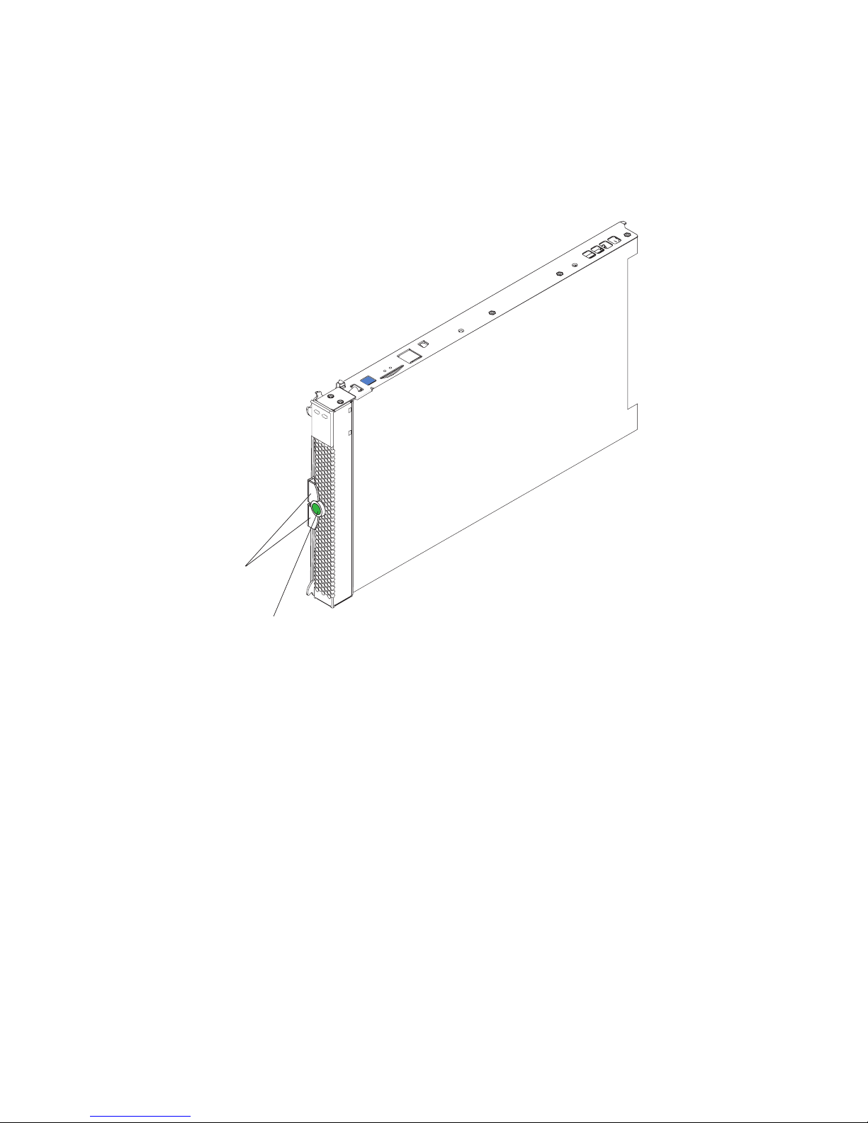
Major Components of the Blade Server
You must remove the blade server from the SBCE unit and remove the cover to see the
components.
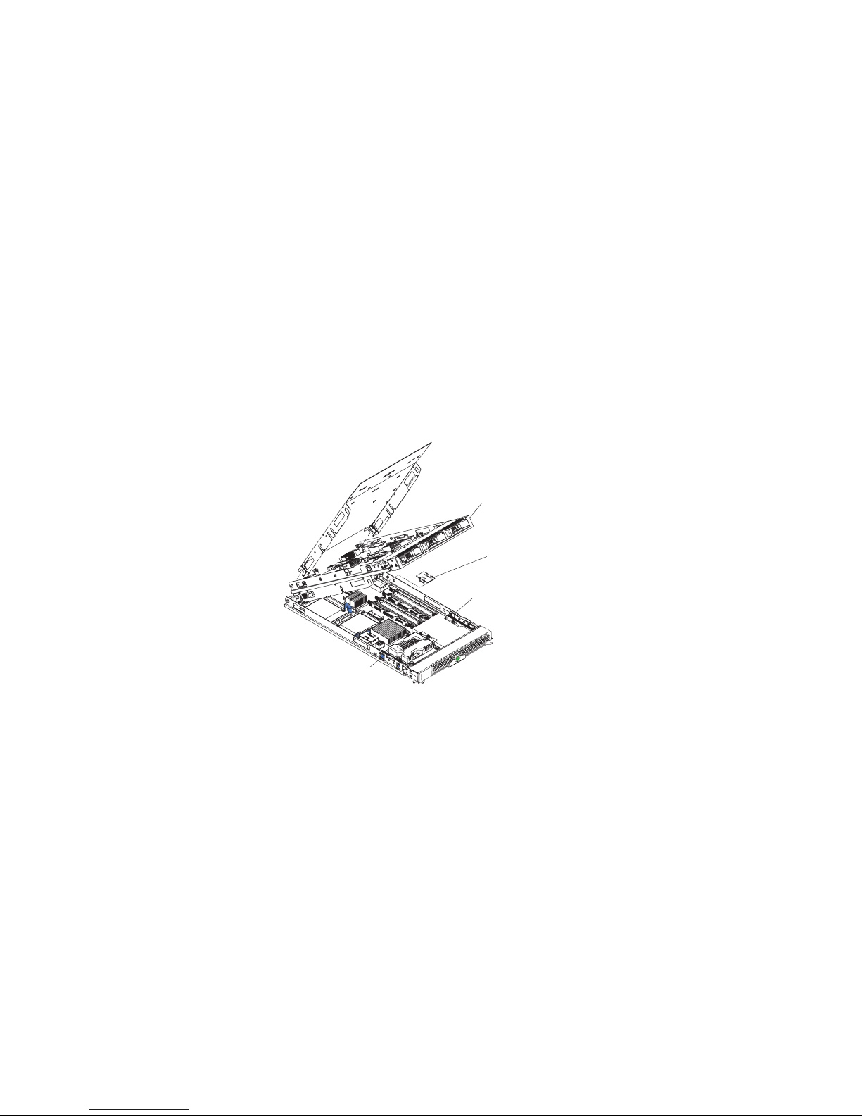
The following illustration shows the major components of the blade server.
SAS hard disk drives
DIMM
Heat sink
Microprocessor 2
Bezel-assembly
release (both sides)
Microprocessor
heat sink filler
Control-Panel
Cable
Microprocessor 1
and heat sink
Bezel
Control-panel
connector
AF000640
8 Intel® Server Compute Blade SBXD132 Installation and User’s Guide
Page 17

2 Power, Controls, Jumpers,
Switches, and Indicators
This chapter describes the power features, how to turn on and turn off the blade server,
and what the controls and indicators mean. This chapter also identifies the system-board
connectors.
Turning on the Blade Server
After you connect the blade server to power through the SBCE unit, the blade server can
start in any of the following ways:
• You can press the power-control button on the front of the blade server (behind the
control panel door, see “Understanding the Control Panel and LEDs” on page 10) to
start the blade server.
Notes:
1. Wait until the power-on LED on the blade server flashes slowly before pressing the
power-control button. While the service processor in the management module is
initializing, the power-on LED does not flash, and the power-control button on the
blade server does not respond.
2. While the blade server is starting, the power-on LED on the front of the blade server
is lit. See “Understanding the Control Panel and LEDs” on page 10 for the power-on
LED states.
• If a power failure occurs, the SBCE unit and then the blade server can start
automatically when power is restored, if the blade server is configured through the
management module to do so.
• You can turn on the blade server remotely by using the management module.
• If the blade server is connected to power (the power-on LED is flashing slowly), the
operating system supports the Wake on LAN feature, and the Wake on LAN feature
has not been disabled through the management module, the Wake on LAN feature can
turn on the blade server. However, the blade server can only receive the Wake on LAN
command through the Ethernet ports that are integrated on the system board, not
through the Ethernet ports on an installed I/O expansion card.
Turning off the Blade Server
When you turn off the blade server, it is still connected to power through the SBCE unit.
The blade server can respond to requests from the service processor, such as a remote
request to turn on the blade server. To remove all power from the blade server, you must
remove it from the SBCE unit.
Intel® Server Compute Blade SBXD132 Installation and User’s Guide 9
Page 18
Shut down the operating system before you turn off the blade server. See the operatingsystem documentation for information about shutting down the operating system.
The blade server can be turned off in any of the following ways:
• You can press the power-control button on the blade server (behind the control panel
door, see “Understanding the Control Panel and LEDs” on page 10). This starts an
orderly shutdown of the operating system, if this feature is supported by the operating
system.
Note: After turning off the blade server, wait at least 5 seconds before you press the
power-control button to turn on the blade server again.
• If the operating system stops functioning, you can press and hold the power-control
button for more than 4 seconds to turn off the blade server.
• The management module can turn off the blade server.
— If the system is not operating correctly, the management module will
automatically turn off the blade server.
— Through the management-module Web interface, you can also configure the
management module to turn off the blade server. For additional information, see
the Intel
Guide.
®
Blade Server Management Module SBCECMM: Installation and User’s
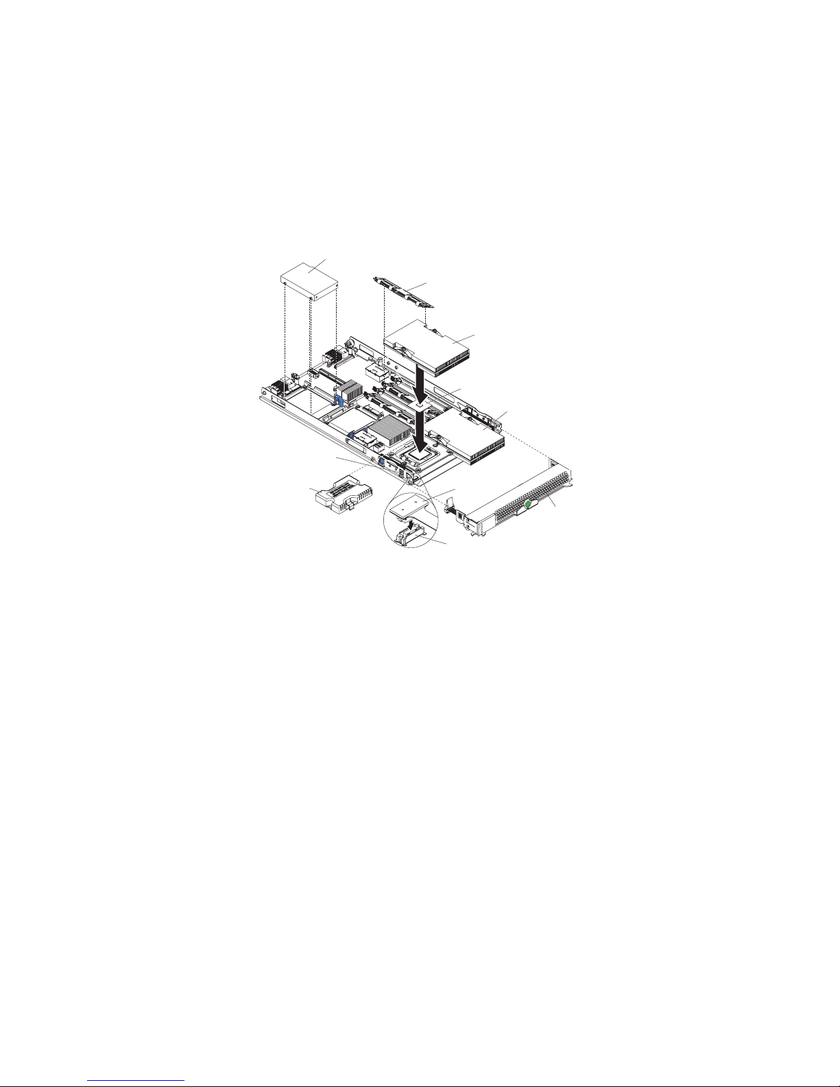
Understanding the Control Panel and LEDs
This section describes the controls and LEDs on the blade server.
Note: The control panel door is shown in the closed (normal) position in the
following illustration. To access the power-control button, you must open the
control panel door.
Activity LED
Location LED
KVM select button
Information LED
Power-control button
Power-on LED
Blade-error LED
Media-tray select
buttom
AF000941
10 Intel® Server Compute Blade SBXD132 Installation and User’s Guide
Page 19

Notes:
Keyboard/video/mouse (KVM) select button: Press this button to associate the shared
SBCE unit keyboard port, video port, and mouse port with the blade server. The LED on
this button flashes while the request is being processed, and then is lit when the ownership
of the keyboard, video, and mouse has been transferred to the blade server. It can take
approximately 20 seconds to switch the keyboard, video, and mouse control to the blade
server.
Using a keyboard that is directly attached to the management-module, you can press
keyboard keys in the following sequence to switch KVM control between blade servers:
NumLock NumLock blade_server_number Enter
Where blade_server_number is the two-digit number for the blade bay in which the
blade server is installed. A blade server that occupies more than one blade bay is
identified by the lowest bay number that it occupies.
If there is no response when you press the KVM select button, you can use the
management-module Web interface to determine whether local control has been disabled
on the blade server.
1. The operating system in the blade server must provide USB support for the blade
server to recognize and use the keyboard and mouse, even if the keyboard and mouse
have PS/2
®
-style connectors.
2. If you install a supported Microsoft* Windows* operating system on the blade server
while it is not the current owner of the keyboard, video, and mouse, a delay of up to 1
minute occurs the first time that you switch the keyboard, video, and mouse to the
blade server. All subsequent switching takes place in the normal KVM switching time
frame (up to 20 seconds).
Media-tray select button: Press this button to associate the shared SBCE unit media tray
(removable-media drives and front-panel USB ports) with the blade server. The LED on
the button flashes while the request is being processed, and then is lit when the ownership
of the media tray has been transferred to the blade server. It can take approximately 20
seconds for the operating system in the blade server to recognize the media tray.
If there is no response when you press the media-tray select button, you can use the
management-module Web interface to determine whether local control has been disabled
on the blade server.
Note: The operating system in the blade server must provide USB support for the
blade server to recognize and use the removable-media drives and front-panel
USB ports.
Activity LED: When this green LED is lit, it indicates that there is activity on the hard
disk drive, or network.
Location LED: When this blue LED is lit, it has been turned on by the system
administrator to aid in visually locating the blade server. The location LED on the SBCE
unit is lit also. The location LED can be turned off through the management-module Web
interface.
Intel® Server Compute Blade SBXD132 Installation and User’s Guide 11
Page 20
Information LED: When this amber LED is lit, it indicates that information about a
system error for the blade server has been placed in the management-module event log.
The information LED can be turned off through the management-module Web interface.
Blade-error LED: When this amber LED is lit, it indicates that a system error has
occurred in the blade server. The blade-error LED will turn off only after the error is
corrected.
Power-control button: This button is behind the control panel door. Press this button to
turn on or turn off the blade server.
Note: The power-control button has effect only if local power control is enabled for
the blade server. Local power control is enabled and disabled through the
management-module Web interface.
Power-on LED: This green LED indicates the power status of the blade server in the
following manner:
• Flashing rapidly: The service processor (BMC) on the blade server is communicating
with the management module.
• Flashing slowly: The blade server has power but is not turned on.
• Lit continuously: The blade server has power and is turned on.
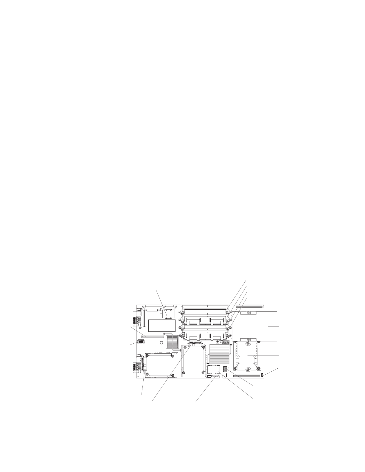
Blade Server Connectors
The following illustration shows the system-board components, including connectors for
user-installable options, for the blade server.
I/O-expansion
option (J134)
I/O-expansion
option (J131)
SAS hard disk drive 1 (J137)
SAS hard disk drive 0 (J136)
Blade-expansion option (J132)
Battery (BH1)
DIMM 4 (J144)
DIMM 3 (J143)
DIMM 2 (J142)
DIMM 1 (J141)
Microprocessor 1
(U66)
Microprocessor 2
(U70)
Control panel
connector (J155)
Power connector (J164)
Memory connector (J150)
12 Intel® Server Compute Blade SBXD132 Installation and User’s Guide
AF002051
Page 21
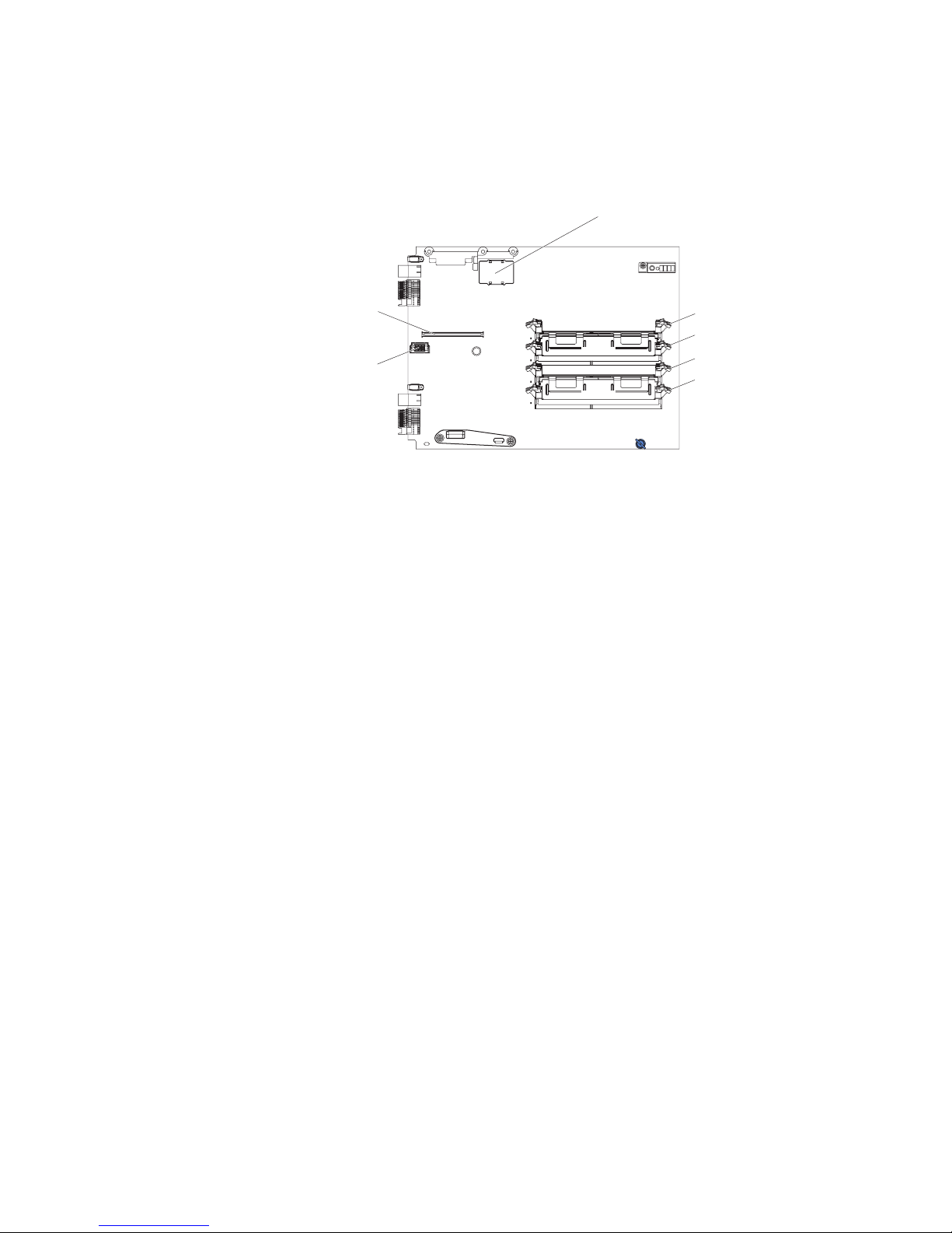
The following illustration shows components for the optional Intel® Blade Server
Memory and I/O Expansion Blade.
Blade-expansion option (J14)
I/O-expansion
option (J17)
I/O-expansion
option (J15)
DIMM8 (J19)
DIMM7 (J18)
DIMM6 (J21)
DIMM5 (J20)
Intel® Server Compute Blade SBXD132 Installation and User’s Guide 13
Page 22

14 Intel® Server Compute Blade SBXD132 Installation and User’s Guide
Page 23

3 Installing Options
This chapter provides instructions for installing hardware options in the blade server.
Some option-removal instructions are provided in case you need to remove one option to
install another.
Installation Guidelines
Before you begin installing options in the blade server, read the following information:
• Read the safety information beginning on page vii and the guidelines in “Handling
Static-sensitive Devices” on page 16. This information will help you work safely with
the blade server and options.
• When you install your new blade server, take the opportunity to download and apply
the most recent firmware updates. This step will help to make sure that any known
issues are addressed and that your blade server is ready to function at maximum levels
of performance. To download firmware updates for your server, go to http://
support.intel.com/support/.
• Observe good housekeeping in the area where you are working. Place removed covers
and other parts in a safe place.
• Back up all important data before you make changes to disk drives.
• Before you remove a blade server from the SBCE unit, you must shut down the
operating system and turn off the blade server. You do not have to shut down the
SBCE unit itself.
• When you are finished working on the blade server, reinstall all safety shields, guards,
labels, and ground wires.
• For a list of supported options for the blade server, go to http://support.intel.com/
support/.
System Reliability Guidelines
To help ensure proper cooling and system reliability, make sure that the following
requirements are met:
• Each microprocessor socket always contains either a microprocessor heat-sink filler
or a microprocessor and heat sink. If the blade server has only one microprocessor, it
must be installed in microprocessor socket 1.
• You do not operate the SBCE unit without a blade server, expansion unit, or filler
blade installed in each blade bay to ensure proper cooling. See the documentation for
your SBCE unit for additional information.
• The blade server battery must be operational. If the battery becomes defective, replace
it immediately. For instructions, see the Intel
Hardware Maintenance and Troubleshooting Guide.
®
Server Compute Blade SBXD132
Intel® Server Compute Blade SBXD132 Installation and User’s Guide 15
Page 24
Handling Static-sensitive Devices
Warni n g : Static electricity can damage the blade server and other electronic devices. To avoid
damage, keep static-sensitive devices in their static-protective packages until you are
ready to install them.
To reduce the possibility of damage from electrostatic discharge, observe the following
precautions:
• Limit your movement. Movement can cause static electricity to build up around you.
• Handle the device carefully, holding it by its edges or its frame.
• Do not touch solder joints, pins, or exposed circuitry.
• Do not leave the device where others can handle and damage it.
• While the device is still in its static-protective package, touch it to an unpainted metal
part of the SBCE unit or any unpainted metal surface on any other grounded rack
component in the rack in which you are installing the device for at least 2 seconds.
This drains static electricity from the package and from your body.
• Remove the device from its package and install it directly into the blade server
without setting it down. If it is necessary to set down the device, put it back into its
static-protective package. Do not place the device on the blade server cover or on a
metal surface.
• Take additional care when you handle devices during cold weather. Heating reduces
indoor humidity and increases static electricity.
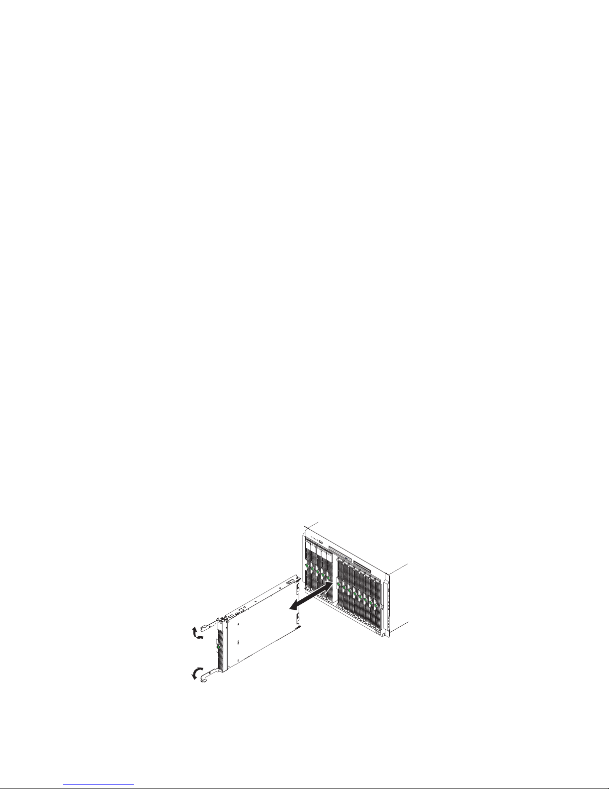
Removing the Blade Server from the Intel® Blade Server
Chassis SBCE
The following illustration shows how to remove a blade server from a SBCE unit. The
appearance of your SBCE unit might be different, see the documentation for your SBCE
unit for additional information.
AF000944
16 Intel® Server Compute Blade SBXD132 Installation and User’s Guide
Page 25
Warni n g: To maintain proper system cooling, do not operate the SBCE unit without a blade server,
expansion unit, or blade filler installed in each blade bay.
Note the bay number. Reinstalling a blade server into a different bay than the one from
which it was removed could have unintended consequences. Some configuration
information and update options are established according to bay number; if you reinstall
the blade server into a different bay, you might need to reconfigure the blade server.
To remove the blade server, complete the following steps:
1. If the blade server is operating, shut down the operating system; then, press the
power-control button (behind the blade server control panel door) to turn off the blade
server (see “Turning off the Blade Server” on page 9 for more information).
Caution: Wait at least 30 seconds, until the hard disk drives stop spinning, before
proceeding to the next step.
2. Open the two release handles as shown in the illustration. The blade server moves out
of the bay approximately 0.6 cm (0.25 inch).
3. Pull the blade server out of the bay.
4. Place either a blade filler or another blade in the bay within 1 minute.
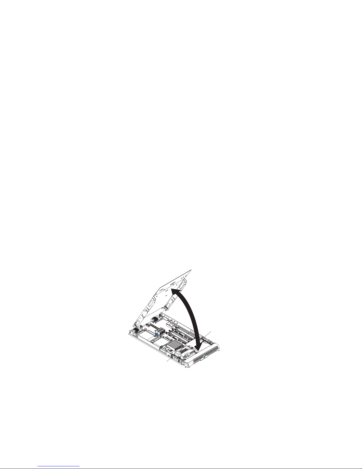
Opening the Blade Server Cover
Note: If the blade server has an expansion unit installed in place of the cover, remove it (see
“Removing an Expansion Unit” on page 18).
The following illustration shows how to open the cover on a blade server.
Blade-cover
release
Blade-cover
release
AF000641
To open the blade server cover, complete the following steps:
1. Read the safety information beginning on page vii and “Installation Guidelines” on
page 15.
Intel® Server Compute Blade SBXD132 Installation and User’s Guide 17
Page 26
2. If the blade server is installed in a SBCE unit, remove it (see “Removing the Blade
Server from the Intel
®
Blade Server Chassis SBCE” on page 16 for instructions).
3. Carefully lay the blade server down on a flat, static-protective surface, with the cover
side up.
4. Press the blade-cover release on each side of the blade server or expansion unit and
lift the cover open, as shown in the illustration.
5. Lay the cover flat, or lift it from the blade server and store for future use.
Caution: Hazardous energy is present when the blade server is connected to the power source.
Always replace the blade cover before installing the blade server.
Removing an Expansion Unit
The following illustration shows how to remove an expansion unit from a blade server.
Storage and I/O
Expansion Blade
Blade
Expansion
Connector
Cover
Blade-Cover
Release
Blade-Cover
Release
AF000642
To remove the expansion unit, complete the following steps:
1. Read the safety information beginning on page vii and “Installation Guidelines” on
page 15.
2. If the blade server is installed in a SBCE unit, remove it (see “Removing the Blade
Server from the Intel
®
Blade Server Chassis SBCE” on page 16 for instructions).
3. Carefully lay the blade server down on a flat, static-protective surface, with the cover
side up.
4. Open the blade server cover, if one is installed (see “Opening the Blade Server Cover”
on page 17 for instructions).
5. Remove the expansion unit:
a. Press the blade-cover release on each side of the blade server.
18 Intel® Server Compute Blade SBXD132 Installation and User’s Guide
Page 27
b. Use the extraction device on the expansion unit, if one is present, to disengage the
expansion unit from the system board. These extraction devices can be of several
types, including thumb screws or levers.
c. Rotate the expansion unit open, as shown in the illustration; then, lift the
expansion unit from the blade server.
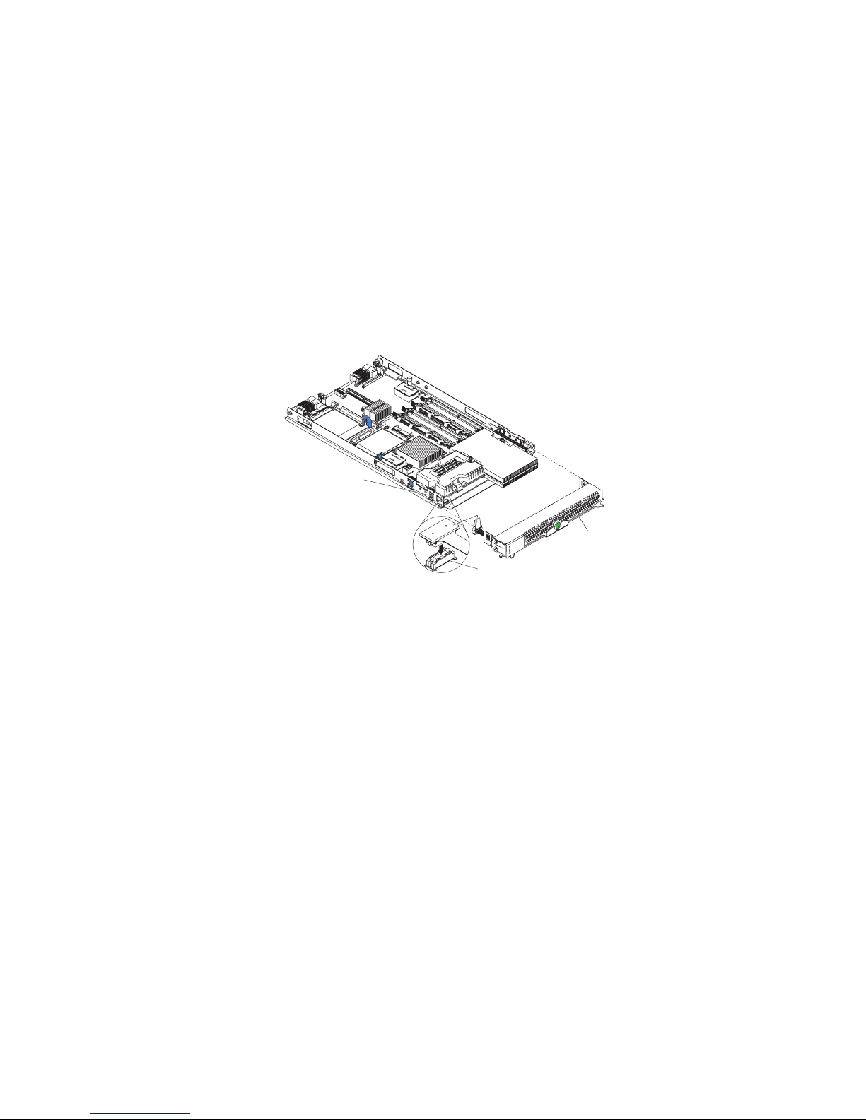
Removing the Blade Server Bezel Assembly
To install certain options, you must first remove the blade server bezel assembly. The
following illustration shows how to remove the bezel assembly.
Bezel-assembly
release (both sides)
Control-Panel
Cable
Bezel
Control-panel
connector
AF000933
To remove the blade server bezel assembly, complete the following steps:
1. Read the safety information beginning on page vii and “Installation Guidelines” on
page 15.
2. Open the blade server cover (see “Opening the Blade Server Cover” on page 17 for
instructions).
3. Press the bezel-assembly release and pull the bezel assembly away from the blade
server approximately 1.2 cm (0.5 inch).
4. Disconnect the control-panel cable from the control-panel connector.
5. Pull the bezel assembly away from the blade server.
6. Store the bezel assembly in a safe place.
Intel® Server Compute Blade SBXD132 Installation and User’s Guide 19
Page 28
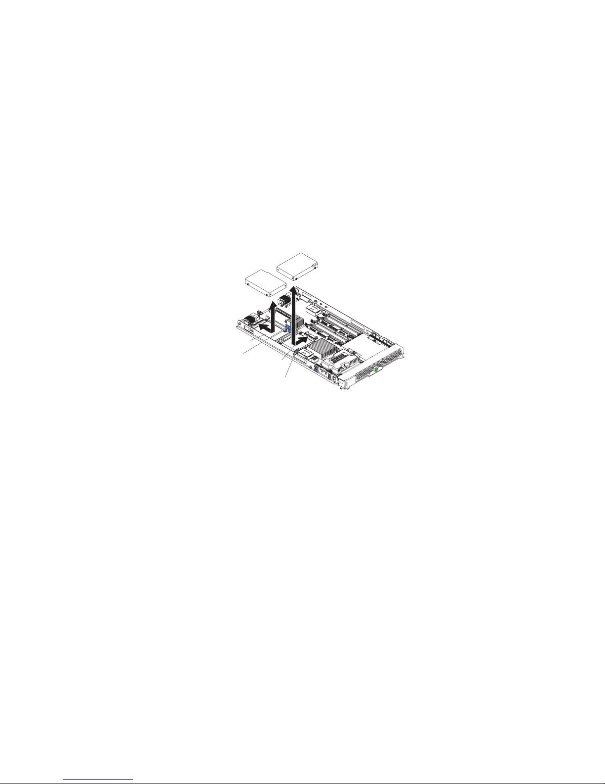
Installing a SAS Hard Disk Drive
The blade server has two connectors on the system board for installing optional SFF SAS
hard disk drives.
Depending on the blade server model, at least one SAS hard disk drive might already be
installed. If the blade server is equipped with one SAS hard disk drive, you can install an
additional SAS hard disk drive. These two SAS hard disk drives can be used to implement
and manage a redundant array of independent disks (RAID) level-1 array. See
“Configuring a RAID Array” on page 63 for information about SAS RAID configuration.
The following illustration shows how to install a SAS hard disk drive.
SAS ID 1
Hard disk drive
release lever
SAS ID 0
Hard disk
drive release
lever
AF000934
Note: Do not install a SAS hard disk drive in SAS connector 1 (SAS ID 1) if you intend to also
install an optional standard-form-factor expansion card. The standard-form-factor
expansion card occupies the same area as the second hard disk drive.
To install a SAS hard disk drive, complete the following steps:
1. Read the safety information beginning on page vii and “Installation Guidelines” on
page 15.
2. Shut down the operating system, turn off the blade server, and remove the blade server
from the SBCE unit (see “Removing the Blade Server from the Intel
®
Blade Server
Chassis SBCE” on page 16 for instructions).
3. Carefully lay the blade server on a flat, static-protective surface.
4. Open the blade server cover (see “Opening the Blade Server Cover” on page 17 for
instructions).
5. Locate SAS connector 0 (J136) or SAS connector 1 (J137).
6. If a standard-form-factor expansion card is installed in the SAS connector 1 location,
complete the following steps:
a. Remove the expansion card (see the illustration in “Installing a Standard-form-
factor Expansion Card” on page 30) and its mounting bracket, and save the screws
that secure the mounting bracket to the system board. Store the screws in a safe
place.
20 Intel® Server Compute Blade SBXD132 Installation and User’s Guide
Page 29
b. Install the SAS connector 1 drive tray. Secure the drive tray to the system board
with the screws from the option kit.
Caution: Do not press on the top of the drive. Pressing on the top might damage the
drive.
7. Put the drive into the tray and push it, from the rear edge of the drive, into the
connector until the drive moves past the lever at the back of the tray.
If you have other options to install or remove, do so now; otherwise, go to “Completing
the Installation” on page 32.
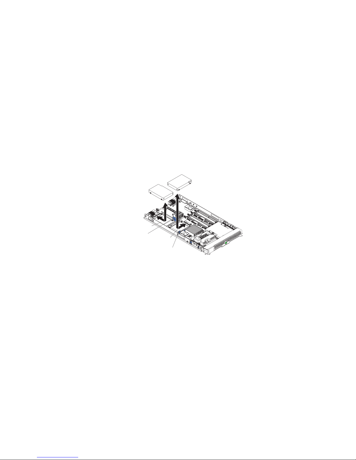
Removing a SAS Hard Disk Drive
The following illustration shows how to remove a SAS hard disk drive.
SAS ID 1
Hard disk drive
release lever
SAS ID 0
Hard disk
drive release
lever
AF000934
To remove a SAS hard disk drive, complete the following steps:
1. Read the safety information beginning on page vii and “Installation Guidelines” on
page 15.
2. Shutdown the operating system, turn off the blade server, and remove the blade server
from the SBCE unit (see “Removing the Blade Server from the Intel
®
Blade Server
Chassis SBCE” on page 16 for instructions).
3. Carefully lay the blade server on a flat, static-protective surface.
4. Open the blade server cover (see “Opening the Blade Server Cover” on page 17 for
instructions).
5. Locate SAS connector 0 (J136) or SAS connector 1 (J137). Slowly pull the blue lever
at the back of the hard disk drive tray away from the hard disk drive to disengage the
drive from its tray.
6. From the rear edge of the drive, slide the drive out of the SAS connector.
Intel® Server Compute Blade SBXD132 Installation and User’s Guide 21
Page 30
Installing Memory Modules
The following notes describe the types of dual inline memory modules (DIMMs) that the
blade server supports and other information that you must consider when installing
DIMMs:
• The system board contains four DIMM connectors. If an optional Intel
Memory and I/O Expansion Blade is installed on your blade server, it provides four
additional DIMM connectors. The server supports two-way memory interleaving.
• The DIMM options that are available for the blade server are 512 MB, 1 GB, 2 GB
and 4 GB. Depending on the memory configuration set in blade server BIOS, the
blade server can support a minimum of 1 GB and a maximum of 16 GB of system
memory in the system board and a maximum of 32 GB of system memory when an
optional Intel
• For blade servers with no Memory and I/O Expansion Blade, when you install
memory, you must install a pair of matched DIMMs. Install the DIMMs in the
following order:
Pair DIMM connectors
First 1 (J141) and 3 (J143)
Second 2 (J142) and 4 (J144)
®
Blade Server Memory and I/O Expansion Blade is installed.
®
Blade Server
• To set up a non-mirrored memory configuration for a blade server with a Memory and
I/O Expansion Blade, when you install memory, you must install a pair of matched
DIMMs. Install the DIMMs in the following order:
Pair DIMM connectors
First 1 (system board J141) and 3 (system board J143)
Second 1 (Memory and I/O Expansion Blade J18) and 3 (Memory
and I/O Expansion Blade J20)
Third 2 (system board J142) and 4 (system board J144)
Fourth 2 (Memory and I/O Expansion Blade J19) and 4 (Memory
and I/O Expansion Blade J21)
• To set up a mirrored memory configuration for a blade server with a Memory and I/O
Expansion Blade, when you install memory, you must install matched DIMMs in
groups of four. Install the DIMMs in the following order:
Pair DIMM connectors
First 1 (system board J141) and 3 (system board J143)
1 (Memory and I/O Expansion Blade J18) and 3 (Memory
and I/O Expansion Blade J20)
22 Intel® Server Compute Blade SBXD132 Installation and User’s Guide
Page 31

Pair DIMM connectors
Second 2 (system board J142) and 4 (system board J144)
2 (Memory and I/O Expansion Blade J19) and 4 (Memory
and I/O Expansion Blade J21)
• All DIMMs in a pair or group must be the same size, speed, type, technology, and
physical design. You can mix compatible DIMMs from different manufacturers.
• All DIMMs must have the same speed. However, different pairs or groups of DIMMs
do not have to be of the same size, type, technology, and physical design.
• Install only fully-buffered double-date rate dual-channel (FB-DDR2), PC2-4200,
registered SDRAM with ECC DIMMs. For a current list of supported DIMMs for the
blade server, see http://support.intel.com/support/.
• Installing or removing DIMMs changes the configuration information for the blade
server. After installing or removing a DIMM, you must change and save the new
configuration information by using the Configuration/Setup Utility program. When
you restart the blade server, it displays a message indicating that the memory
configuration has changed. Start the Configuration/Setup Utility program and select
Save Settings (see “Configuration/Setup Utility Menu Choices” on page 58 for more
information).
DIMM
Retaining clip
To install a DIMM, complete the following steps:
1. Read the safety information beginning on page vii and “Installation Guidelines” on
page 15.
2. Read the documentation that comes with the DIMMs.
3. Shut down the operating system, turn off the blade server, and remove the blade server
from the SBCE unit (see “Removing the Blade Server from the Intel
®
Blade Server
Chassis SBCE” on page 16 for instructions).
4. Carefully lay the blade server on a flat, static-protective surface.
5. Open the blade server cover (see “Opening the Blade Server Cover” on page 17 for
instructions).
Intel® Server Compute Blade SBXD132 Installation and User’s Guide 23
Page 32

6. If a Memory and I/O Expansion Blade is installed and you are installing DIMMs on
the system board, remove the expansion blade (see “Removing an Expansion Unit” on
page 18).
7. Locate the DIMM connectors (see the illustrations in “Blade Server Connectors” on
page 12). Determine the connectors into which you will install the DIMMs.
8. Touch the static-protective package that contains the DIMM to any unpainted metal
surface on the SBCE unit or any unpainted metal surface on any other grounded rack
component in the rack in which you are installing the DIMM for at least 2 seconds;
then, remove the DIMM from its package.
9. To install the DIMMs, repeat the following steps for each DIMM that you install:
a. Turn the DIMM so that the DIMM keys align correctly with the connector on the
system board.
Caution: To avoid breaking the retaining clips or damaging the DIMM connectors,
handle the clips gently.
b. Insert the DIMM by pressing the DIMM along the guides into the connector. Make
sure that the retaining clips snap into the closed positions.
Important: If there is a gap between the DIMM and the retaining clips, the DIMM
has not been correctly installed. In this case, open the retaining clips and
remove the DIMM; then, reinsert the DIMM.
10. If you have other options to install or remove, do so now; otherwise, go to
“Completing the Installation” on page 32.
If memory is installed in the Memory and I/O Expansion Blade, it can be configured to
provide memory mirroring using the Configuration/Setup Utility program. See Advanced
Setup -> Memory Settings under “Configuration/Setup Utility Menu Choices” on
page 58 for more information.
Installing an Additional Microprocessor
The blade server comes with at lease one microprocessor. If the blade server comes with
one microprocessor, you can install a second microprocessor. If more than one
microprocessor is installed, the blade server can now operate as a symmetric
multiprocessing (SMP) server. With SMP, certain operating systems and application
programs can distribute the processing load between the microprocessors.
Notes:
1. You can not remove the single microprocessor and replace it with a different type of
microprocessor of greater or lesser speed.
2. If you install a second microprocessor, you must install the same microprocessor type
and speed as the first microprocessor.
To use SMP, obtain an SMP-capable operating system. For a list of supported operating
systems and other options, go to http://support.intel.com/support/.
24 Intel® Server Compute Blade SBXD132 Installation and User’s Guide
Page 33

The following notes describe the type of microprocessor that the server supports and other
information that you must consider when installing a microprocessor:
• Always install microprocessors that have the same cache size and type, the same
clock speed, and identical internal and external clock frequencies (including system
bus speed).
• Make sure that the microprocessor with the lowest feature set is the startup (bootstrap)
microprocessor, which is installed in the microprocessor 1 socket (U66).
• For a list of microprocessors that the blade server supports, go to http://
support.intel.com/support/.
• Before installing a new microprocessor, download and install the most current level of
BIOS code, from http://support.intel.com/support/.
• The microprocessors terminate themselves; therefore, no terminator card is required if
microprocessor socket 2 is empty. However, for proper airflow, this socket must
contain a microprocessor heat-sink filler, sometimes called a microprocessor baffle.
• The microprocessor speeds are automatically set for this server; therefore, you do not
have to set any microprocessor frequency-selection jumpers or switches.
The following illustration shows how to install the second microprocessor on the system
board for the blade server.
Heat sink
Microprocessor 2
Microprocessor 1
and heat sink
Microprocessor
heat sink filler
To install an additional microprocessor, complete the following steps:
1. Read the safety information beginning on page vii and “Installation Guidelines” on
page 15.
2. Shut down the operating system, turn off the blade server, and remove the blade server
from the SBCE unit (see “Removing the Blade Server from the Intel
®
Blade Server
Chassis SBCE” on page 16 for instructions).
3. Carefully lay the blade server on a flat, static-protective surface.
4. Open the blade server cover (see “Opening the Blade Server Cover” on page 17 for
instructions).
5. Remove the bezel assembly (see “Installing the Blade Server Bezel Assembly” on
page 33 for instructions).
6. Locate the microprocessor socket on the system board.
Intel® Server Compute Blade SBXD132 Installation and User’s Guide 25
Page 34

7. Remove the two screws that secure the heat-sink filler and then remove the filler from
the microprocessor socket.
Install the microprocessor:
Caution: Do not touch the pins in the microprocessor socket. Touching these pins
might result in permanent damage to the system board.
Microprocessor
release lever
Microprocessor
dust cover
a. Remove the protective cover from the microprocessor retainer, if one is present.
Caution: Do not use any tools or sharp objects to lift the locking lever on the
microprocessor socket. Doing so might result in permanent damage to the
system board.
b. Rotate the locking lever on the microprocessor socket from its closed and locked
position until it stops in the fully open position (approximately a 135° angle), as
shown.
c. Rotate the microprocessor retainer on the microprocessor socket from its closed
position until it stops in the fully open position (approximately a 135° angle), as
shown.
d. Touch the static-protective package that contains the new microprocessor to any
unpainted metal surface on the blade server or any unpainted metal surface on any
other grounded rack component in the rack you are installing the microprocessor
in for at least 2 seconds; then, remove the microprocessor from the package.
e. Remove the cover from the bottom of the microprocessor.
Microprocessor
Alignment marks
Microprocessor
socket
26 Intel® Server Compute Blade SBXD132 Installation and User’s Guide
Page 35

8. Center the microprocessor over the microprocessor socket. Align the triangle on the
corner of the microprocessor with the triangle on the corner of the socket and
carefully place the microprocessor into the socket.
Caution:
-- Do not press the microprocessor into the socket.
-- Make sure that the microprocessor is oriented and aligned correctly in the
socket before you try to close the microprocessor retainer.
f. Carefully close the microprocessor retainer.
g. Rotate the locking lever on the microprocessor socket to the closed and locked
position. Make sure that the lever is secured in the locked position by the tab on
the microprocessor socket.
9. Install a heat sink on the microprocessor.
Caution:
-- Do not set down the heat sink after you remove the plastic cover.
-- Do not touch the thermal grease on the bottom of the heat sink. Touching the
thermal grease will contaminate it. If the thermal grease on the
microprocessor or heat sink becomes contaminated, contact your service
technician.
Heat sink Thermal grease
a. Remove the plastic protective cover from the bottom of the heat sink.
b. Make sure that the thermal material is still on the bottom of the heat sink; then,
align and place the heat sink on top of the microprocessor in the retention bracket,
thermal material side down. Press firmly on the heat sink.
c. Align the two screws on the heat sink with the holes on the heat-sink retention
module.
d. Press firmly on the captive screws and tighten them with a screwdriver, alternating
between screws until they are tight. If possible, each screw should be rotated two
full rotations at a time. Repeat until the screws are tight. Do not overtighten the
screws by using excessive force. If you are using a torque wrench, tighten the
screws to 8.5 to 13 Newton-meters (Nm) (6.3 to 9.6 foot-pounds).
10. If you have other options to install or remove, do so now; otherwise, go to
“Completing the Installation” on page 32.
Intel® Server Compute Blade SBXD132 Installation and User’s Guide 27
Page 36

Installing an I/O-expansion Card
If I/O-expansion is supported by the SBCE unit in which the blade server is installed, you
can add an I/O-expansion card to the blade server. An I/O expansion card provides
additional connections for communicating on a network.
The blade server supports various types of I/O expansion cards. See http://
support.intel.com/support/ for a list of available I/O expansion cards and their form-factor
types.
Make sure that the SBCE unit and the I/O modules to which the I/O expansion card is
mapped support the network-interface type of the I/O expansion card. For example, if you
add an Ethernet expansion card to a blade server installed in a SBCE unit, the I/O-modules
in I/O-module bays 3 and 4 on the SBCE unit must both be compatible with the expansion
card. All other expansion cards that are installed on other blade servers in the SBCE unit
must also be compatible with these I/O-modules. In this example, you could then install
two Ethernet switch modules, two pass-thru modules, or one Ethernet switch module and
one pass-thru module. Because pass-thru modules are compatible with a variety of I/Oexpansion cards, installing two pass-thru modules would enable the use of several
different types of compatible I/O-expansion cards on blade servers within the same SBCE
unit.
The following sections describe how to install an I/O-expansion card in the blade server.
The illustrations show installation of the I/O-expansion cards in the system board:
installing the cards in an expansion unit is similar.
28 Intel® Server Compute Blade SBXD132 Installation and User’s Guide
Page 37

Installing a Small-form-factor Expansion Card
The following illustration shows how to install a small-form-factor expansion card.
Small-form-factor
expansion
card
PRESS HEREWHEN
INSTALLING CARD
To install a small-form-factor expansion card, complete the following steps:
1. Read the safety information beginning on page vii and “Installation Guidelines” on
page 15.
2. Shut down the operating system, turn off the blade server, and remove the blade server
from the SBCE unit (see “Removing the Blade Server from the Intel
®
Blade Server
Chassis SBCE” on page 16 for instructions).
3. Carefully lay the blade server on a flat, static-protective surface.
4. Open the cover (see “Opening the Blade Server Cover” on page 17 for instructions).
5. If a Memory and I/O Expansion Blade is installed and you are installing the expansion
card on the system board, remove the expansion blade (see “Removing an Expansion
Unit” on page 18).
6. Touch the static-protective package that contains the expansion card to any unpainted
metal surface on the SBCE unit or any unpainted metal surface on any other grounded
rack component; then, remove the expansion card from the package.
7. Locate the expansion-card connector and orient the expansion card.
8. Slide the notch in the narrow end of the card into the raised hook on the expansion
card bracket; then, gently pivot the card into the expansion card connectors.
Note: For device-driver and configuration information needed to complete the
installation of the expansion card, see the documentation that comes with the
expansion card.
9. If you have other options to install or remove, do so now; otherwise, go to
“Completing the Installation” on page 32.
Intel® Server Compute Blade SBXD132 Installation and User’s Guide 29
Page 38

Installing a Standard-form-factor Expansion Card
If a SAS drive is connected to SAS connector 1 (J137), you must remove it and the SAS
drive tray before you can install a standard-form-factor expansion card and expansion
card bracket on the system board (see “Removing a SAS Hard Disk Drive” on page 21).
You cannot have both a drive that is connected to SAS connector 1 and a standard-formfactor expansion card installed in the system board of the blade server. If you are
removing the SAS disk drive, backup any information on it that you want to keep to
another storage device.
If the SAS hard disk drive that is installed in SAS connector 1 is part of a RAID array,
delete the SAS RAID array before removing the drive. When you delete the RAID array,
the array configuration information is removed, but no data is deleted.
The following illustration shows how to install a standard-form-factor expansion card.
Standard-form-factor
expansion card
Expansion
card
bracket
INSTALLING CARD
PRESS HEREWHEN
Hard disk
drive tray
To install a standard-form-factor expansion card, complete the following steps:
1. Read the safety information beginning on page vii and “Installation Guidelines” on
page 15.
2. Shut down the operating system, turn off the blade server, and remove the blade server
from the SBCE unit (see “Removing the Blade Server from the Intel
®
Blade Server
Chassis SBCE” on page 16 for instructions).
3. Carefully lay the blade server on a flat, static-protective surface.
4. Open the cover (see “Opening the Blade Server Cover” on page 17 for instructions).
5. If a Memory and I/O Expansion Blade is installed and you are installing the expansion
card on the system board, remove the expansion blade (see “Removing an Expansion
Unit” on page 18).
6. If you are installing the expansion card in the system board and a drive is connected to
SAS connector 1, remove the drive and tray (see “Removing a SAS Hard Disk Drive”
on page 21 for instructions), and save the screws that secure the tray to the system
board. Store the screws in a safe place.
30 Intel® Server Compute Blade SBXD132 Installation and User’s Guide
Page 39

7. Touch the static-protective package that contains the expansion card to any unpainted
metal surface on the SBCE unit or any unpainted metal surface on any other grounded
rack component; then, remove the expansion card from the package.
8. Install the expansion card bracket, if it is not already installed. Secure the bracket to
the system board with the screws from the option kit or from the removed drive tray.
9. Locate the expansion-card connector and orient the expansion card.
10. Slide the notch in the narrow end of the card into the raised hook on the expansion
card bracket; then, gently pivot the wide end of the card into the expansion-card
connectors.
Note: For device-driver and configuration information to complete the installation
of the expansion card, see the documentation that comes with the expansion
card.
11. If you have other options to install or remove, do so now; otherwise, go to
“Completing the Installation” on page 32.
Installing an Expansion Unit
Note: If an Intel® Blade Storage Expansion Module for the Intel® Server Compute Blade
SBXD132 is installed on a blade server with a Memory and I/O Expansion Blade,
installation of standard-form-factor or small-form-factor expansion cards in the Intel®
Blade Storage Expansion Module is not supported.
The following illustration shows how to install an expansion unit on a blade server.
Storage and I/O
Expansion Blade
Blade
Expansion
Connector
Cover
Blade-Cover
Release
Blade-Cover
Release
AF000642
To install an expansion unit, complete the following steps:
1. Read the safety information that begins on page vii and “Installation Guidelines” on
page 15.
2. If you removed the blade bezel assembly, replace it now (see “Installing the Blade
Server Bezel Assembly” on page 33 for instructions).
Intel® Server Compute Blade SBXD132 Installation and User’s Guide 31
Page 40

3. Remove the protective covers from the blade expansion connectors, if they are
present.
Note: For some expansion units, you only need to remove the cover closest to the
rear of the blade server.
4. If you are installing a Memory and I/O Expansion Blade on the blade server, remove
the power jumper from power connector J164. Store the power jumper in a safe place.
5. Touch the static-protective package that contains the expansion unit to any unpainted
metal surface on the SBCE unit or any unpainted metal surface on any other grounded
rack component; then, remove the expansion unit from the package.
6. Install the expansion unit:
a. Orient the expansion unit as shown in the illustration.
b. Lower the expansion unit so that the slots at the rear slide down onto the cover pins
at the rear of the blade server.
c. Close the expansion unit (see the documentation for the expansion unit for
information and instructions):
-- If the expansion unit has an extraction device, pivot the expansion unit
closed; then, use the extraction device to fully seat the expansion unit on the
system board. These extraction devices can be of several types, including
thumb screws or levers.
-- If the expansion unit has no extraction device, pivot the expansion unit
closed; then, press the expansion unit firmly into place until the blade-cover
releases click.
The connectors on the expansion unit automatically align with and connect to the
connectors on the system board.
7. If you have other expansion units to install, do so now; otherwise, go to “Completing
the Installation” on page 32.
Completing the Installation
To complete the installation, complete the following tasks. Instructions for each task are in
the following sections.
1. Reinstall the blade server bezel assembly, if you removed it (see “Installing the Blade
Server Bezel Assembly” on page 33 for information on installing the bezel assembly).
2. Reinstall the Memory and I/O Expansion Blade, if you removed it to install other
options (see “Installing an Expansion Unit” on page 31 for information on installing
the Memory and I/O Expansion Blade).
3. Close the blade server cover, unless you installed an optional expansion unit that has
its own cover (see “Closing the Blade Server Cover” on page 34).
32 Intel® Server Compute Blade SBXD132 Installation and User’s Guide
Page 41

Caution: Hazardous energy is present when the blade server is connected to the
power source. Always replace the blade cover before installing the blade
server.
4. Reinstall the blade server into the SBCE unit (see “Installing the Blade Server in an
®
Intel
Blade Server Chassis SBCE” on page 35).
5. Turn on the blade server (see “Turning on the Blade Server” on page 9).
6. For certain options, run the blade server Configuration/Setup Utility program (see
Chapter 6, “Configuring the Blade Server”).
Note: If you have just connected the power cords of the SBCE unit to electrical
outlets, you must wait until the power-on LED on the blade server flashes
slowly before you press the power-control button.
Installing the Blade Server Bezel Assembly
The following illustration shows how to install the bezel assembly.
Bezel-assembly
release (both sides)
Control-Panel
Cable
Bezel
Control-panel
connector
AF000933
To install the blade server bezel assembly, complete the following steps:
1. Read the safety information beginning on page vii and “Installation Guidelines” on
page 15.
2. Connect the control-panel cable to the control-panel connector on the system board.
3. Carefully slide the bezel assembly onto the blade server until it clicks into place.
Intel® Server Compute Blade SBXD132 Installation and User’s Guide 33
Page 42

Closing the Blade Server Cover
Attention: You cannot insert the blade server into the SBCE unit until the cover is
installed and closed or an expansion unit is installed. Do not attempt to override this
protection.
The following illustration shows how to close the blade server cover.
Blade-cover
release
Blade-cover
release
AF000641
To close the blade server cover, complete the following steps:
1. Read the safety information beginning on page vii and “Installation Guidelines” on
page 15.
2. If you removed the blade bezel assembly, replace it now (see “Installing the Blade
Server Bezel Assembly” on page 33 for instructions).
3. If a Memory and I/O Expansion Blade is not installed on the blade server, make sure
that the power jumper is installed in power connector J164.
4. Lower the cover so that the slots at the rear slide down onto the pins at the rear of the
blade server, as shown in the illustration. Before closing the cover, make sure that all
components are installed and seated correctly and that you have not left loose tools or
parts inside the blade server.
5. Pivot the cover to the closed position, as shown in the illustration, until it clicks into
place.
34 Intel® Server Compute Blade SBXD132 Installation and User’s Guide
Page 43

Installing the Blade Server in an Intel® Blade Server Chassis SBCE
The following illustration shows how to install a blade server into a chassis. The
appearance of your SBCE unit might be different, see the documentation for your SBCE
unit for additional information.
AF000944
To install a blade server in a SBCE unit, complete the following steps.
Caution: Hazardous energy is present when the blade server is connected to the power source.
Always replace the blade cover before installing the blade server.
Notes:
1. Read the safety information beginning on page vii and “Installation Guidelines” on
page 15 through “Handling Static-sensitive Devices” on page 16.
2. If you have not done so already, install any options that you want, such as SAS drives
or memory, in the blade server.
3. Select the bay for the blade server; at least one blade bay is required.
• When any blade server or option is in blade bays 7 through 14, power modules must
be present in all four power-module bays. For additional information, see the
Installation and User’s Guide that comes with the SBCE unit.
• To help ensure proper cooling, performance, and system reliability, make sure that
each blade bay on the front of the SBCE unit contains a blade server, expansion unit,
or blade filler. Do not operate a SBCE unit for more than 1 minute without a blade
server, expansion unit, or blade filler in each blade bay.
4. Make sure that the release handles on the blade server are in the open position
(perpendicular to the blade server).
5. Slide the blade server into the blade bay until it stops.
6. Push the release handles on the front of the blade server to the closed position.
7. Turn on the blade server (see “Turning on the Blade Server” on page 9 for
instructions).
Intel® Server Compute Blade SBXD132 Installation and User’s Guide 35
Page 44

8. Make sure that the power-on LED on the blade server control panel is lit continuously,
indicating that the blade server is receiving power and is turned on.
9. If you have other blade servers to install, do so now.
If you reinstall a blade server that you removed, you must install it in the same blade bay
from which you removed it. Some blade server configuration information and update
options are established according to bay number. Reinstalling a blade server into a
different blade bay from the one from which it was removed could have unintended
consequences, and you might have to reconfigure the blade server.
If this is the initial installation for the blade server in the SBCE unit, you must configure
the blade server through the Configuration/Setup Utility program and install the blade
server operating system. See “Updating the Blade Server Configuration” on page 36 and
Chapter 7, “Installing the Operating System” for details.
Updating the Blade Server Configuration
When the blade server starts for the first time after you add or remove an internal option,
you might receive a message that the configuration has changed. The Configuration/Setup
Utility program automatically starts so that you can save the new configuration settings.
See “Using the Configuration/Setup Utility program” on page 57 for more information
about the Configuration/Setup Utility program.
Some options have device drivers that you must install. See the documentation that comes
with each option for information about installing device drivers.
The blade server comes with at least one microprocessor. If more than one microprocessor
is installed, the blade server can operate as a symmetric multiprocessing (SMP) server.
You might have to upgrade the operating system to support SMP. See Chapter 7,
“Installing the Operating System” and your operating-system documentation for
additional information.
Input/output Connectors and Devices
The input/output connectors that are available to the blade server are supplied by the
SBCE unit. See the documentation that comes with the SBCE unit for information about
the input/output connectors.
The blade server has two selection buttons on the control panel: the media tray select
button and the keyboard/video/mouse select button. See “Understanding the Control Panel
and LEDs” on page 10 for information about these buttons and their functions.
The Ethernet controllers on the blade server communicate with the network through the
Ethernet-compatible I/O modules on the SBCE unit. Network signals to and from the
blade server or any expansion cards are automatically routed to a same-network-interface
I/O module through circuitry in the SBCE unit.
36 Intel® Server Compute Blade SBXD132 Installation and User’s Guide
Page 45

4 Memory and I/O Expansion for the
Intel® Server Compute Blade
SBXD132
Memory and I/O expansion for the Intel® Server Compute Blade SBXD132 is provided
by installation of an optional expansion unit, which can support up to four additional dualinline memory (DIMM) connectors. The memory and I/O expansion unit can also support
installation of standard-form-factor and small-form-factor cards, as well as a storage
expansion unit, such as the Intel® Blade Storage Expansion Module (see “Intel® Blade
Storage Expansion Module for the Intel
for additional details).
Note: If an Intel® Blade Storage Expansion Module is installed on the Memory and I/O
Expansion Unit then installation of standard-form-factor or small-form-factor expansion
cards are not supported in the Intel® Blade Storage Expansion Module.
The following illustration shows the memory and I/O expansion unit and some of the
available optional components.
®
Server Compute Blade SBXD132” on page 39
Intel® Server Compute Blade SBXD132 Installation and User’s Guide 37
Page 46

38 Intel® Server Compute Blade SBXD132 Installation and User’s Guide
Page 47

5 Intel® Blade Storage Expansion
Module for the Intel® Server
Compute Blade SBXD132
The Intel® Blade Storage Expansion Module for the Intel® Server Compute Blade
SBXD132 is a redundant array of independent disks (RAID) storage device which can be
installed on a blade server that supports Serial Attached SCSI (SAS) hard disk drives (see
the Tested Hardware and Operating System List at http://support.intel.com/support/ to see
if your blade server supports this expansion unit). The expansion unit has an intelligent
RAID controller and cache memory that can support RAID level-0, level-1, and level-5
(depending on the model). It supports RAID configurations that use up to three hot-swap
SAS hard disk drives in the expansion unit and up to two hard disk drives that are installed
in the host blade server.
The expansion unit also supports up to two I/O-expansion cards (standard-form-factor,
and small-form-factor) to provide additional network connections and has a blade
expansion connector that allows another expansion unit to be installed.
Notes:
• The illustrations in this document might differ slightly from your hardware.
Installation Guidelines
Before you install the expansion unit on a blade server, read the following information:
• Read the safety information that begins on page vii and the guidelines in “Handling
Static-sensitive Devices” on page 40. This information will help you work safely.
• Observe good housekeeping in the area where you are working. Place removed covers
and other parts in a safe place.
Intel® Blade Storage Expansion
Module for Intel® Server
Compute Blade SBXD132
Drive fillers
Hot-swap hard disk drive
AF000935
Intel® Server Compute Blade SBXD132 Installation and User’s Guide 39
Page 48

• Back up all important data before you make changes to disk drives.
• Before you remove a blade server from the SBCE unit, you must shut down the
operating system and turn off the blade server. You do not have to shut down the
SBCE unit itself.
• Blue on a component indicates touch points, where you can grip the component to
remove it from or install it in the blade server, or open or close a latch.
System Reliability Considerations
To help ensure proper cooling and system reliability, make sure that:
• Each of the blade bays on the front of the SBCE unit contains either a blade server,
expansion unit or filler.
• A removed blade server or filler is replaced within 1 minute of removal.
• Each of the hard disk drive bays in the expansion unit contains either a hot-swap SAS
hard disk drive or a filler.
Handling Static-sensitive Devices
Note: Static electricity can damage electronic devices and your blade server. To avoid damage,
keep static-sensitive devices in their static-protective packages until you are ready to
install them.
To reduce the possibility of damage from electrostatic discharge, observe the following
precautions:
• Limit your movement. Movement can cause static electricity to build up around you.
• Handle the device carefully, holding it by its edges or its frame.
• Do not touch solder joints, pins, or exposed printed circuitry.
• Do not leave the device where others can handle and damage it.
• While the device is still in its static-protective package, touch it to an unpainted metal
part of the SBCE unit or any unpainted metal surface on any other grounded rack
component in the rack in which you are installing the device for at least 2 seconds.
This drains static electricity from the package and from your body.
• Remove the device from its package and install it directly on the blade server without
setting the device down. If it is necessary to set down the device, put it back into its
static-protective package. Do not place the device on your SBCE unit or on a metal
surface.
• Take additional care when handling devices during cold weather. Heating reduces
indoor humidity and increases static electricity.
40 Intel® Server Compute Blade SBXD132 Installation and User’s Guide
Page 49

Notices and Statements used in this Document
e
The following notices and statements are used in the documentation:
• Note: These notices provide important tips, guidance, or advice.
• Important: These notices provide information or advice that might help you avoid
inconvenient or problem situations.
• Attention: These notices indicate possible damage to programs, devices, or data. An
attention notice is placed just before the instruction or situation in which damage
could occur.
• Caution: These statements indicate situations that can be potentially hazardous to
you. A caution statement is placed just before the description of a potentially
hazardous procedure step or situation.
• Danger: These statements indicate situations that can be potentially lethal or
extremely hazardous to you. A danger statement is placed just before the description
of a potentially lethal or extremely hazardous procedure step or situation.
Installing the Expansion Unit
Notes:
1. The expansion unit can be installed only on a blade server that supports SAS hard
disk drives (see the Tested Hardware and Operating System List at http://
support.intel.com/support/ to see if your blade server supports this expansion unit).
2. After you install the expansion unit on a host blade server, the combined unit will
occupy one additional blade bay in the SBCE unit than the host blade server alone.
The following illustrations show how to install the expansion unit.
Intel® Blade Storage
Expansion Module for
Intel® Server Comput
Blade SBXD132
Blade expansion
connector cover
AF000936
Intel® Server Compute Blade SBXD132 Installation and User’s Guide 41
Page 50

Complete the following steps to install the expansion unit:
1. Read the Safety information beginning on page vii and “Installation Guidelines” on
page 39.
2. If the host blade server is installed in a SBCE unit, shut down the operating system
and turn off the blade server; then, remove the blade server from the SBCE unit (see
the documentation that comes with the blade server for more information).
3. Carefully lay the blade server on a flat, static-protective surface.
4. Open the blade server cover and lift it off of the blade server (see the documentation
that comes with the blade server for more information).
5. Locate the blade expansion connector near the rear of the host blade server and
remove the cover from the connector.
6. Touch the static-protective package that contains the expansion unit to any unpainted
metal surface on the SBCE unit or any unpainted metal surface on another grounded
rack component; then, remove the expansion unit from the package.
7. Orient the expansion unit over the blade server.
8. Lower the expansion unit so that the slots at the rear slide down onto the pins at the
rear of the blade server.
9. Pivot the expansion unit closed and press it firmly into place until the cover-release
latches click. The connector on the expansion unit automatically aligns with and
connects to the blade expansion connector on the blade server.
10. Install a ServeRAID
™
SAS controller in the expansion unit (see “Installing a
ServeRAID SAS Controller” on page 45).
11. If you have I/O-expansion cards to install in the expansion unit, do so now (see
“Installing an I/O-expansion Card” on page 47); otherwise, go to “Completing the
Installation” on page 51.
42 Intel® Server Compute Blade SBXD132 Installation and User’s Guide
Page 51

Installing the Expansion Unit Cover
The following illustration shows how to install the expansion unit cover.
Note: Once the expansion unit is installed on the host blade server, the blade server cover is
used as the expansion unit cover.
Cover
Cover
release
Cover
release
AF000937
Complete the following steps to install the expansion unit cover:
1. Read the Safety information beginning on page vii and “Installation Guidelines” on
page 39.
2. Orient the cover over the expansion unit.
3. Lower the cover so that the slots at the rear slide down onto the pins at the rear of the
expansion unit.
4. Pivot the cover closed and press it firmly into place until the cover-release latches
click.
Caution: Hazardous energy is present when the blade is connected to the power source. Always
replace the blade cover before installing the blade.
Intel® Server Compute Blade SBXD132 Installation and User’s Guide 43
Page 52

Removing the Expansion Unit Cover
The following illustration shows how to remove the expansion unit cover.
Cover
Cover
release
Cover
release
AF000938
Complete the following steps to remove the expansion unit cover:
1. Read the Safety information beginning on page vii and “Installation Guidelines” on
page 39.
2. If the host blade server and expansion unit are installed in a SBCE unit, shut down the
operating system and turn off the blade server; then, remove the combined blade
server and expansion unit from the SBCE unit (see the documentation that comes with
the blade server for more information).
3. Carefully lay the combined unit down on a flat, static-protective surface, with the
cover side up.
4. Press the cover release on each side of the expansion unit and lift the cover open.
5. Lift the-cover from the expansion unit and store it for future use.
Caution: Hazardous energy is present when the blade server is connected to the power source.
Always replace the blade cover before installing the blade server.
44 Intel® Server Compute Blade SBXD132 Installation and User’s Guide
Page 53

Installing a ServeRAID SAS Controller
The Intel® Blade Storage Expansion Module SBESAS comes with a ServeRAID SAS
Controller that supports RAID level-0 and level-1. An optional ServeRAID SAS
Controller AB256BSE (256-MB cache memory and battery backup for the Intel® Blade
Storage Expansion Module SBESAS) is also available that supports RAID level-0,
level-1, and level-5. You must install one of these SAS controllers before you can create
and use the RAID.
Complete the following steps to install a ServeRAID SAS Controller:
1. Read the Safety information beginning on page vii and “Installation Guidelines” on
page 39.
2. If the host blade server and expansion unit are installed in a SBCE unit, shut down the
operating system and turn off the blade server; then, remove the combined blade
server and expansion unit from the SBCE unit (see the documentation that comes with
the blade server for more information).
3. Carefully lay the combined unit down on a flat, static-protective surface, with the
cover side up.
4. Remove the cover from the expansion unit (see “Removing the Expansion Unit
Cover” on page 44).
To install a ServeRAID SAS Controller, complete the following steps.
Controller socket
SAS
controller
Retaining
clips
1. Touch the static-protective package that contains the ServeRAID SAS Controller to
any unpainted metal surface on the SBCE unit or any unpainted metal surface on any
other grounded rack component; then, remove the SAS controller from the package.
2. Make sure that both of the controller socket retaining clips are in the fully open
position.
3. Orient the SAS controller so that the keys align correctly with the controller socket.
Intel® Server Compute Blade SBXD132 Installation and User’s Guide 45
Page 54

Caution: To avoid breaking the retaining clips or damaging the controller socket,
s
open and close the clips gently.
4. Insert the SAS controller by pressing it along the guides into the connector socket.
Make sure that the retaining clips snap into the closed position.
To install a ServeRAID SAS Controller AB256BSE, complete the following steps.
Push pins
SAS
controller
RAID battery
connector
(underside of
controller)
RAID battery
Controller socket
Retaining clip
Battery holder
1. Touch the static-protective package that contains the RAID battery to any unpainted
metal surface on the SBCE unit or any unpainted metal surface on any other grounded
rack component; then, remove the RAID battery from the package.
2. Place the RAID battery into position on the battery holder.
3. Insert the two push pins until they lock the battery into place in the battery holder.
4. Touch the static-protective package that contains the ServeRAID SAS Controller
AB256BSE to any unpainted metal surface on the SBCE unit or any unpainted metal
surface on any other grounded rack component; then, remove the SAS controller from
the package.
5. Connect the RAID battery cable to the connector on the underside of the controller.
Note: Route the RAID battery cable over the top of the SAS controller to make sure
that it does not interfere with the installation.
6. Make sure that both of the controller socket retaining clips are in the fully open
position.
7. Orient the SAS controller so that the keys align correctly with the controller socket.
46 Intel® Server Compute Blade SBXD132 Installation and User’s Guide
Page 55

Caution: To avoid breaking the retaining clips or damaging the controller socket,
open and close the clips gently.
8. Insert the SAS controller by pressing it along the guides into the connector socket.
Make sure that the retaining clips snap into the closed position.
9. If you have I/O-expansion cards to install in the expansion unit, do so now (see
“Installing an I/O-expansion Card” on page 47); otherwise, go to “Completing the
Installation” on page 51.
Installing an I/O-expansion Card
You can install up to two I/O-expansion cards in the expansion unit to provide additional
connections for communicating on a network. The following illustration shows the
locations of the connectors and the different form factors of the supported I/O-expansion
cards in the expansion unit.
Shared I/O-expansion
connectors
A
A
Shared I/O-expansion
connectors
B
Blade
B
expansion
connector
AF000939
Before installing an I/O-expansion card, consider the following information:
• The expansion unit supports two different form factors of I/O-expansion cards:
standard form factor (A) and small form factor (B).
• Either a standard-form-factor or a small-form-factor card can be installed in each pair
of the shared connectors, (1 and 2).
• The network-interface type of the I/O-expansion card must be supported by the
corresponding I/O modules in the SBCE unit.
— Connector 1 provides a connection to SBCE unit I/O bays 1 and 2.
— Connector 2 provides a connection to SBCE unit I/O bays 3 and 4.
To install an I/O-expansion card, complete the following steps:
1. Read the Safety information beginning on page vii and “Installation Guidelines” on
page 39.
2. If the host blade server and expansion unit are installed in a SBCE unit, complete the
following steps:
Intel® Server Compute Blade SBXD132 Installation and User’s Guide 47
Page 56

a. Shut down the operating system and turn off the blade server; then, remove the
combined blade server and expansion unit from the SBCE unit (see the
documentation that comes with the blade server for more information).
b. Carefully lay the combined unit down on a flat, static-protective surface, with the
cover side up.
c. Remove the cover from the expansion unit (see “Removing the Expansion Unit
Cover” on page 44).
3. Touch the static-protective package that contains the expansion card to any unpainted
metal surface on the SBCE unit or any unpainted metal surface on any other grounded
rack component; then, remove the expansion card from the package.
4. To install a small-form-factor expansion card, complete the following steps.
Note: The following illustration shows how to install a small-form-factor expansion
card in the rear connectors of the expansion unit; installing a card in the
connectors closest to the front of the expansion unit is similar.
Small-form-factor
expansion card
PRESS H
IN
ST
ALLING CARD
ERE
W
HEN
a. Locate the expansion-card connectors and orient the expansion card above them.
b. Slide the notch in the narrow end of the card into the raised hook on the
expansion-card bracket; then, gently pivot the card into the expansion-card
connectors.
48 Intel® Server Compute Blade SBXD132 Installation and User’s Guide
Page 57

5. To install a standard-form-factor expansion card, complete the following steps.
Note: The following illustration shows how to install a standard-form-factor expansion card in
the rear connectors of the expansion unit; installing a card in the connectors closest to the
front of the expansion unit is similar.
Standard-form-factor
expansion card
INSTALLING CARD
PRESS HEREWHEN
a. Locate the expansion-card connectors and orient the expansion card above them.
b. Slide the notch in the narrow end of the card into the raised hook on the
expansion-card bracket; then, gently pivot the wide end of the card into the
expansion-card connectors.
Intel® Server Compute Blade SBXD132 Installation and User’s Guide 49
Page 58

Installing a Hot-swap SAS Hard Disk Drive
After you have installed the expansion unit on the blade server, you can install up to three
hot-swap SAS hard disk drives in the expansion unit.
Note: You do not have to turn off the blade server to install or remove hot-swap hard disk drives
from the expansion unit.
The following illustration shows how to install a hot-swap SAS hard disk drive.
Blade server
Expansion unit
Drive
filler
Hard disk drive
activity LED
Hard disk drive
status LED
Drive handle
(open)
AF000940
Complete the following steps to install a hot-swap SAS hard disk drive in the expansion
unit.
Caution: To maintain proper system cooling, do not operate the SBCE unit for more than 1 minute
without either a hard disk drive or a drive filler installed in each hard disk drive bay.
1. Read the Safety information beginning on page vii and “Installation Guidelines” on
page 39.
2. Select the hot-swap bay in which you want to install the hard disk drive.
3. Firmly grasp the drive filler that is in the bay and pull it out of the expansion unit.
4. If you are installing a new hard disk drive, touch the static-protective package that
contains the drive to any unpainted metal surface on the SBCE unit or any unpainted
metal surface on any other grounded rack component; then, remove the drive from the
package.
5. Make sure that the drive handle is in the open position (perpendicular to the drive).
6. Align the hard disk drive with the guide rails in the bay.
7. Gently push the hard disk drive into the bay until the drive stops.
8. Push the drive handle to the closed (locked) position.
50 Intel® Server Compute Blade SBXD132 Installation and User’s Guide
Page 59

Caution: Make sure that a drive filler is installed in any disk drive bay that does
not contain a hard disk drive.
9. Make sure that the host blade server is turned on; then, check the hard disk drive
LEDs to make sure that the drive is operating correctly.
— If the green hard disk drive activity LED is flashing, the drive is being accessed.
— If the amber hard disk drive status LED is lit continuously, that drive is faulty and
must be replaced.
Completing the Installation
To complete the installation, complete the following tasks:
1. Install the cover on the expansion unit (see “Installing the Expansion Unit Cover” on
page 43).
2. Insert the combined blade server and expansion unit into the SBCE unit.
Note: Make sure that the SBCE unit has the required number of power modules
present to supply power to the blade bay in which the expansion unit is
installed. For additional information, see the documentation that comes with
the SBCE unit.
3. If you have hot-swap hard disk drives to install in the expansion unit, do so now (see
“Installing a Hot-swap SAS Hard Disk Drive” on page 50). Make sure that a drive
filler is installed in any disk drive bay that does not contain a hard disk drive.
4. Turn on the blade server.
5. If you have just installed a ServeRAID SAS controller, complete the following steps:
a. If you want to include the host blade server hard disk drives in the expansion unit
RAID, use the configuration utility in the blade server to enable this option (see
the documentation that comes with the blade server for more information).
b. Use a RAID configuration program to create and manage the RAID (see
“Configuring the Expansion Unit RAID Array” on page 52 for more information).
Intel® Server Compute Blade SBXD132 Installation and User’s Guide 51
Page 60

Configuring the Expansion Unit RAID Array
After installing a new ServeRAID SAS controller in the expansion unit, you must
configure the RAID array before it can be used. Basic RAID configuration can be
performed using either the Adaptec RAID Configuration Utility or the ServeRAID
Manager program. The ServeRAID Manager program also provides additional
configuration features.
Using the Adaptec RAID Configuration Utility Program
Use the Adaptec RAID Configuration Utility program to perform the following tasks:
• Create a RAID array
• View the RAID configuration and associated devices
Starting the Adaptec RAID Configuration Utility Program
To start the Adaptec RAID Configuration Utility program, complete the following steps:
1. Turn on the server.
2. When the prompt <<< Press <CTRL><A> for Adaptec
RAID Configuration Utility! >>> appears, press Ctrl+A.
3. To select a choice from the menu, use the arrow keys to highlight it and press Enter.
Adaptec RAID Configuration Utility Menu Choices
The following choices are on the Adaptec RAID Configuration Utility menu:
• Array Configuration Utility
Select this choice to create, manage, or delete arrays, or to initialize drives.
• Serial Select Utility
Select this choice to configure the controller interface definitions or to configure the
physical transfer and SAS address of the selected drive.
• Disk Utilities
Select this choice to format a disk or verify the disk media. Select a device from the
list and read the instructions on the screen carefully before making a selection.
Creating a RAID Array
To create a RAID array, complete the following steps:
1. Start the Adaptec RAID Configuration Utility program (see “Starting the Adaptec
RAID Configuration Utility Program” on page 52).
2. Select Array Configuration Utility.
3. From the Main menu, select Create Array.
52 Intel® Server Compute Blade SBXD132 Installation and User’s Guide
Page 61

Note: Hard disk drives in an array can have different capacities, but the RAID
controller treats them as if they all have the capacity of the smallest hard disk
drive.
4. From the list of available drives, select the drives that you want to include in the array
and press Enter.
5. From the list of RAID levels available, select the one you want to use.
6. Follow the instructions on the screen to complete the configuration; then, select Done
to exit.
7. Restart the server.
Viewing the Array Configuration
To view information about the RAID array, complete the following steps:
1. Start the Adaptec RAID Configuration Utility program (see “Starting the Adaptec
RAID Configuration Utility Program” on page 52).
2. Select Array Configuration Utility.
3. From the Main menu, select Manage Arrays.
4. Select an array and press Enter.
5. To exit from the program, press Esc.
Using the ServeRAID Manager Program
The ServeRAID Support CD contains the ServeRAID Manager program, which you can
use to configure the hard disk drives for use with the ServeRAID SAS controller in the
expansion unit. For details about using this programs, see the documentation that comes
on the IBM ServeRAID Support CD.
Light Path Diagnostics*
Light path diagnostics is a system of LEDs on the system board of the expansion unit.
When an error occurs, these LEDs can be lit to help identify the source of the error.
To view the light path LEDs, remove the blade server and expansion unit from the SBCE
unit; then, press and hold the light path diagnostics switch for a maximum of 25 seconds.
The light path diagnostics LED will be lit to indicate that there is enough power present to
light the error LEDs, and the LED for the failing component also will be lit.
Intel® Server Compute Blade SBXD132 Installation and User’s Guide 53
Page 62

The following illustration shows the locations of the light path LEDs on the expansion
unit system board.
SAS controller battery error LED
SAS controller error LED
Light path diagnostics switch
Host blade error LED
Expansion unit error LED
Lit light path
diagnostics LED
Expansion unit
error (amber)
Host blade error
(amber)
Light path
diagnostics
(green)
SAS controller
battery error
(amber)
Light path diagnostics LED
The following table describes the LEDs on the expansion unit system board and suggested
actions to correct the detected problems. Follow the suggested actions in the order in
which they are listed in the Action column until the problem is solved.
Description Action
A system board error has occurred in the
expansion unit.
A system board error has occurred on the host
blade server.
The light path LEDs on the expansion unit
system board have power.
The SAS controller battery has failed. 1. Reseat the SAS controller battery cable.
Check for error LEDs that are lit on the
expansion unit system board.
Reseat the following components:
1. SAS controller
2. SAS controller battery.
3. Expansion unit.
4. Replace the expansion unit.
Remove the expansion unit from the blade
server and check the blade server for errors
(see the documentation that comes with the
blade server for more information).
Check for error LEDs that are lit on the
expansion unit system board.
2. Replace the SAS controller battery.
54 Intel® Server Compute Blade SBXD132 Installation and User’s Guide
Page 63

Lit light path
diagnostics LED
Description Action
SAS controller
error (amber)
An error has occurred in the SAS controller. 1. Reseat the SAS controller.
2. Replace the SAS controller.
3. Replace the expansion unit.
Intel® Server Compute Blade SBXD132 Installation and User’s Guide 55
Page 64

56 Intel® Server Compute Blade SBXD132 Installation and User’s Guide
Page 65

6 Configuring the Blade Server
This chapter describes the configuration requirements for the blade server. Before you
continue, you should make sure that the blade server has the latest version of firmware
code. For additional information, see “Firmware Updates” on page 61.
The following configuration programs come with the blade server:
• Configuration/Setup Utility program
The Configuration/Setup Utility program is part of the basic input/output system
(BIOS) code in the blade server. Use it to change system settings, such as interrupt
requests (IRQ), date and time, and passwords. See “Using the Configuration/Setup
Utility program” on page 57 for more information.
• LSI Logic Configuration Utility program
The LSI Logic Configuration Utility program is part of the BIOS code in the blade
server. Use it to set the device scan order and to set the SAS controller IDs. See
“Using the LSI Logic Configuration Utility Program” on page 63 for more
information.
• Preboot Execution Environment (PXE) boot agent utility program
The PXE boot agent utility program is part of the BIOS code in the blade server. Use
it to select the boot protocol and other boot options and to select a power-management
option. For information about using this utility program, see “Using the PXE Boot
Agent Utility Program” on page 61.
Using the Configuration/Setup Utility program
To start the Configuration/Setup Utility program, complete the following steps:
1. Turn on the blade server (see “Turning on the Blade Server” on page 9).
2. Immediately give the blade server control of the SBCE unit shared keyboard, video,
and mouse ports.
— If you are managing the blade server using the system console, press the KVM
select button on the blade server (see “Understanding the Control Panel and
LEDs” on page 10 for information).
— If you are managing the blade server from a remote location, see the Intel® Blade
Server Management Module SBCECMM Installation and User’s Guide, Intel®
Server Blade Chassis Enterprise Management Module CBCECMM2: Installation
and User’s Guide, Intel® Blade Server Chassis SBCE: Management Module
Command-Line Interface Reference Guide, or Intel® Blade Server Chassis
SBCE: Serial Over LAN (SOL) Setup Guide for information and instructions.
3. When the Configuration/Setup utility message appears, press F1.
4. Follow the instructions on the screen.
Intel® Server Compute Blade SBXD132 Installation and User’s Guide 57
Page 66

Configuration/Setup Utility Menu Choices
The following choices are on the Configuration/Setup Utility main menu. Depending on
the version of the BIOS code in the blade server, some menu choices might differ slightly
from these descriptions.
• System Summary
Select this choice to display configuration information, including the type, speed, and
cache sizes of the microprocessors and the amount of installed memory. When you
make configuration changes through other options in the Configuration/Setup Utility
program, the changes are reflected in the system summary; you cannot change
settings directly in the system summary.
— Processor Summary
Select this choice to view information about the microprocessors installed in the
blade server.
— USB Device Summary
Select this choice to view information about the USB devices installed in the
blade server.
• System Information
Select this choice to display information about the blade server. When you make
configuration changes through other options in the Configuration/Setup Utility
program, some of those changes are reflected in the system information; you cannot
change settings directly in the system information.
— Product Data
Select this choice to view the machine type and model of the blade server, the
serial number, and the revision level or issue date of the BIOS and diagnostics
code stored in electrically erasable programmable ROM (EEPROM).
• Devices and I/O Ports
Select this choice to view or change assignments for devices and input/output (I/O)
ports.
You can also enable or disable the integrated SAS and Ethernet controllers, all
standard ports (such as serial), and the I/O-expansion card. Enable is the default
setting for all controllers. If you disable a device, it cannot be configured, and the
operating system will not be able to detect it (this is equivalent to disconnecting the
device). If you disable the Ethernet controller, the blade server will have no Ethernet
capability.
With an optional Intel® Blade Storage Expansion Module for the Intel
Compute Blade SBXD132, you can control all of the SAS hard disk drives in the host
blade server. Set BSE3 Controls All Blade SAS HDD to Enable to control all of the
hard disk drives in the host blade server.
— Remote Console Redirection
Select this choice to enable Serial over LAN (SOL) and to set remote console
communication parameters.
— Video
Select this choice to view information about the integrated video controller.
®
Server
58 Intel® Server Compute Blade SBXD132 Installation and User’s Guide
Page 67

— System MAC Addresses
Select this choice to set and view the MAC addresses for the Ethernet controllers
on the blade server.
• Date and Time
Select this choice to set the system date and time, in 24-hour format
(hour:minute:second).
• System Security
Select this choice to set a power-on password. See “Using Passwords” on page 61 for
more information about passwords.
• Start Options
Select this choice to view or change the start options. Changes in the start options take
effect when you start the blade server.
— Startup Sequence Options
Select this choice to view the startup device sequence that is set for the blade
server.
Note: To set the startup sequence, which is the order in which the blade server
checks devices to find a boot record, you must use the management-module
Web interface.
You can set keyboard operating characteristics, such as whether the blade server starts
with the keyboard number lock on or off. You can enable the blade server to run
without a diskette drive or keyboard.
You can enable or disable the PXE option for either of the integrated Gigabit Ethernet
controllers. The default setting is Planar Ethernet 1, which enables the PXE option
for the first Ethernet controller on the system board.
If you enable the boot fail count, the BIOS default settings will be restored after three
consecutive failures to find a boot record.
You can enable a virus-detection test that checks for changes in the boot record when
the blade server starts.
This choice is on the full Configuration/Setup menu only.
• Advanced Setup
Select this choice to change settings for advanced hardware features.
Important: The blade server might malfunction if these options are incorrectly
— Memory Settings
Select this choice to manually enable a pair of memory connectors.
If a memory error is detected during POST or memory configuration, the blade
server automatically disables the failing memory pair of memory connectors and
continues operating with reduced memory. After the problem is corrected, you
must enable the memory connectors. Use the arrow keys to highlight the pair of
memory connectors that you want to enable, and use the arrow keys to select
Enable.
Intel® Server Compute Blade SBXD132 Installation and User’s Guide 59
configured. Follow the instructions on the screen carefully.
Page 68

To maintain optimum system operation in the event of a memory failure, you can
set the Memory Configuration for memory Mirroring or Sparing. Memory
mirroring stores duplicate data on two DIMMs to prevent data loss if a DIMM
fails. Memory sparing removes the failed memory from the system configuration
and activates a Hot Spare Memory pair of DIMMs to replace the failed memory
pair of DIMMs. Before you can enable the memory mirroring or sparing, at least
two pairs of DIMMs must be installed in the blade server that adhere to the
special requirements described in “Installing Memory Modules” on page 22. Set
the Memory Configuration to Flat to disable memory mirroring and sparing.
Note: Memory mirroring is available only when an optional Intel® Blade Server
Memory and I/O Expansion Blade is installed on the blade server.
— CPU Options
Select this choice to disable the microprocessor cache or to set the microprocessor
cache to use the write-back or the write-through method. Write-back caching
generally provides better system performance.
You can also select this choice to enable or disable hyper-threading and adjust
microprocessor performance settings. If enabled, hyper-threading will only be
active if it is supported by your operating system.
— PCI Bus Control
Select this choice to view and set interrupts for PCI devices and to configure the
master-latency-timer value for the blade server.
— Baseboard Management Controller (BMC) Settings
Select this choice to enable or disable the Reboot on System NMI option on the
menu. If you enable this option, the blade server will automatically restart 60
seconds after the service processor issues a nonmaskable interrupt (NMI) to the
blade server. You can also select this choice to enable or disable and set the timeouts for the POST and OS loader watchdog timers and view BMC version
information.
-- BMC Network Configuration
Select this choice to set the network addresses of the BMC.
-- BMC System Event Log
Select this choice to view and clear BMC event log entries.
• Save Settings
Select this choice to save the changes you have made in the settings.
• Restore Settings
Select this choice to cancel the changes you have made in the settings and restore the
previous settings.
• Load Default Settings
Select this choice to cancel the changes you have made in the settings and restore the
factory settings.
• Exit Setup
60 Intel® Server Compute Blade SBXD132 Installation and User’s Guide
Page 69

Select this choice to exit from the Configuration/Setup Utility program. If you have
not saved the changes you have made in the settings, you are asked whether you want
to save the changes or exit without saving them.
Using Passwords
From the System Security choice, you can set, change, and delete a power-on password.
If you set a power-on password, you must type the power-on password to complete the
system startup and to have access to the full Configuration/Setup Utility menu.
You can use any combination of up to seven characters (A–Z, a–z, and 0–9) for the
password. Keep a record of your password in a secure place.
If you forget the power-on password, you can regain access to the blade server in by
removing the blade server battery and then reinstalling it, or by using the power-on
password override switch (see the Intel
Maintenance and Troubleshooting Guide on the Resource CD for instructions).
®
Server Compute Blade SBXD132 Hardware
Using the PXE Boot Agent Utility Program
Use the Preboot Execution Environment (PXE) boot agent utility program to select the
boot protocol and other boot options and to select a power-management option.
Note: The blade server does not support Remote Program Load (RPL) selection for the boot
protocol option.
To start the PXE boot agent utility program, complete the following steps:
1. Turn on the server.
2. When the Broadcom NetXtreme Boot Agent vX.X.X prompt appears,
press Ctrl+S. You have 2 seconds (by default) to press Ctrl+S after the prompt
appears.
If the PXE setup prompt is not displayed, use the Configuration/Setup Utility program
to set the Enable Ethernet PXE/DHCP option.
3. Use the arrow keys or press Enter to select a choice from the menu.
4. Follow the instructions on the screen to change the settings of the selected items; then,
press Enter.
Firmware Updates
Intel periodically makes BIOS, service processor (BMC), and diagnostic firmware
updates available for the blade server. Before you install the blade server in a SBCE unit,
go to http://support.intel.com/support/ to download the latest firmware for the blade
server. Install the updates, using the instructions that are included with the downloaded
files.
Intel® Server Compute Blade SBXD132 Installation and User’s Guide 61
Page 70

Important: To avoid problems and to maintain proper system performance, always make sure that the
BIOS, service processor (BMC), and diagnostic firmware levels are consistent for all
blade servers within the SBCE unit.
Configuring the Gigabit Ethernet Controllers
Two Ethernet controllers are integrated on the blade server system board. Each controller
provides a 1000-Mbps full-duplex interface for connecting to one of the Ethernetcompatible I/O-modules in I/O-module bays 1 and 2, which enables simultaneous
transmission and reception of data on the Ethernet local area network (LAN). Each
Ethernet controller on the system board is routed to a different I/O-module in I/O-module
bay 1 or bay 2. The routing from an Ethernet controller to I/O-module bay will vary based
on blade server type and the operating system that is installed. See “Blade Server Ethernet
Controller Enumeration” on page 62 for information about how to determine the routing
from an Ethernet controller to an I/O-module bay for the blade server.
®
Note: Other types of blade servers, such as the Intel
installed in the same SBCE unit as the Intel
different Ethernet controller routing. See the documentation that comes with the other
blade servers for information.
You do not have to set any jumpers or configure the controllers for the blade server
operating system. However, you must install a device driver to enable the blade server
operating system to address the Ethernet controllers. For device drivers and information
about configuring the Ethernet controllers, see the Broadcom NetXtreme Gigabit Ethernet
Software CD that comes with the blade server. For updated information about configuring
the controllers, see http://support.intel.com/support/.
Server Compute Blade SBX82, that are
®
Server Compute Blade SBXD132 might have
The Ethernet controllers in your blade server support failover, which provides automatic
redundancy for the Ethernet controllers. Without failover, you can have only one Ethernet
controller from each server attached to each virtual LAN or subnet. With failover, you can
configure more than one Ethernet controller from each server to attach to the same virtual
LAN or subnet. Either one of the integrated Ethernet controllers can be configured as the
primary Ethernet controller. If you have configured the controllers for failover and the
primary link fails, the secondary controller takes over. When the primary link is restored,
the Ethernet traffic switches back to the primary Ethernet controller. See the operatingsystem device-driver documentation for information about configuring for failover.
Important: To support failover on the blade server Ethernet controllers, the Ethernet switch modules
in the SBCE unit must have identical configurations.
Blade Server Ethernet Controller Enumeration
The enumeration of the Ethernet controllers in a blade server is operating-system
dependent. You can verify the Ethernet controller designations that a blade server uses
through the operating-system settings.
62 Intel® Server Compute Blade SBXD132 Installation and User’s Guide
Page 71

The routing of an Ethernet controller to a particular I/O-module bay depends on the type
of blade server. You can verify which Ethernet controller is routed to which I/O-module
bay by using the following test:
1. Install only one Ethernet switch module or pass-thru module in I/O-module bay 1.
2. Make sure that the ports on the switch module or pass-thru module are enabled (click
I/O-module Tasks “Management” Advanced Management in the management
module Web-based user interface).
3. Enable only one of the Ethernet controllers on the blade server. Note the designation
that the blade server operating system has for the controller.
4. Ping an external computer on the network connected to the switch module or passthru module. If you can ping the external computer, the Ethernet controller that you
enabled is associated with the switch module or pass-thru module in I/O-module bay
1. The other Ethernet controller in the blade server is associated with the switch
module or pass-thru module in I/O-module bay 2.
If you have installed an I/O-expansion card in the blade server, communications from the
expansion card are routed to I/O-module bays 3 and 4. You can verify which controller on
the card is routed to which I/O-module bay by performing the same test and using a
controller on the expansion card and a compatible switch module or pass-thru module in I/
O-module bay 3 or 4.
Configuring a RAID Array
Configuring a SAS RAID array applies to a blade server in which two SAS hard disk
drives are installed.
Two SAS hard disk drives in the blade server can be used to implement and manage RAID
level-0 (striping) or RAID level-1 (mirror) arrays in operating systems that are listed on
http://support.intel.com/support/. For the blade server, you must configure the SAS RAID
using the LSI Configuration Utility program.
If an optional Intel® Blade Storage Expansion Module for the Intel
Blade SBXD132 is installed, you can use it to control all of the SAS hard disk drives
installed in the blade server. You enable this feature using the Configuration/Setup Utility
program (see Devices and I/O Ports on page 58 for information and instructions).
®
Using the LSI Logic Configuration Utility Program
You can use the LSI Logic Configuration Utility program to:
• Set the SAS device scan order
• Set the SAS ID for the controller
• Manage the SAS RAID configuration
Server Compute
Intel® Server Compute Blade SBXD132 Installation and User’s Guide 63
Page 72

Starting the LSI Logic Configuration Utility program
To start the LSI Logic Configuration Utility program, complete the following steps:
1. Turn on the blade server (make sure that the blade server is the owner of the keyboard,
video, and mouse) and watch the monitor screen.
2. When the <<<Press Ctrl-C to start LSI Logic Configuration
Utility>>> prompt appears, press Ctrl-C.
3. Use the arrow keys to select the controller from the list of adapters; then, press Enter.
4. Follow the instructions on the screen to change the settings of the selected items; then,
press Enter. If you select SAS Topology or Advanced Adapter Properties,
additional screens are displayed.
64 Intel® Server Compute Blade SBXD132 Installation and User’s Guide
Page 73

7 Installing the Operating System
Important:
1. The operating system in the blade server must provide USB support for the blade
server to recognize and use the keyboard, mouse, and removable-media drives. The
®
Intel
Blade Server Chassis SBCE uses USB for internal communication with these
devices.
2. Some operating systems enable you to select the type of mouse that is being used. If
you are offered this choice, select USB instead of PS/2. Although the mouse might be a
PS/2-style device, communication with the mouse is through an internal USB bus in
the SBCE unit; therefore, the operating system in the blade server must recognize the
mouse as a USB device.
Intel® Server Compute Blade SBXD132 Installation and User’s Guide 65
Page 74

66 Intel® Server Compute Blade SBXD132 Installation and User’s Guide
Page 75

8 Solving Problems
This chapter provides basic information about the diagnostic tools that are available to
help you solve some common problems that might occur while you are setting up the
blade server.
If you install the blade server in the SBCE unit and the blade server does not start, perform
the following actions:
• Make sure that the SBCE unit is correctly connected to a power source.
• Reseat the blade server in the SBCE unit (see “Installing the Blade Server in an Intel
Blade Server Chassis SBCE” on page 35).
• If the power-on LED is flashing slowly, turn on the blade server (see “Turning on the
Blade Server” on page 9).
• If you have just added a new optional device or component, make sure that it is
correctly installed and compatible with the blade server and its components. If the
device or component is not compatible, remove it from the blade server, reinstall the
blade server in the SBCE unit, and then restart the blade server.
If the blade server does not start after you have performed the preceding actions, see the
®
Server Compute Blade SBXD132 Hardware Maintenance and Troubleshooting
Intel
Guide on the Resource CD.
®
Diagnostic Tools Overview
The following tools are available to help you diagnose and solve hardware-related
problems:
• POST beep codes
The power-on self-test beep codes can indicate the detection of a problem.
— One beep indicates successful completion of POST
— Repeating long beeps indicate a memory error. Make sure that all DIMMs are
correctly installed.
— Additional beep codes are listed under “Diagnostics” in the Hardware
Maintenance and Troubleshooting Guide for your blade server type.
• POST error codes
The POST error codes indicate the detection of a problem. See the Hardware
Maintenance and Troubleshooting Guide for more information.
• Troubleshooting tables
Use the troubleshooting tables to find solutions to problems that have identifiable
symptoms. These tables are in the Hardware Maintenance and Troubleshooting Guide
for your blade server.
Intel® Server Compute Blade SBXD132 Installation and User’s Guide 67
Page 76

• Diagnostic programs and error messages
Real Time Diagnostics tests the major components of the Intel
including the management modules, I/O-modules, removable media drives, and the
blade servers, while the operating system is running. See the Hardware Maintenance
and Troubleshooting Guide for more information.
Note: If you are unable to find the system error logs in the blade-server firmware
code, view the system event log in the chassis management module.
®
blade server system,
• Light path diagnostics
Use light path diagnostics LEDs on the system board to identify system errors. If the
system-error LED on the system LED panel on the front or rear of the SBCE unit is
lit, one or more error LEDs on the SBCE unit components also might be lit. These
LEDs help identify the cause of the problem. Blade server error LEDs are described in
the Hardware Maintenance and Troubleshooting Guide for your blade server.
68 Intel® Server Compute Blade SBXD132 Installation and User’s Guide
Page 77

A Warranty
Limited Warranty for Intel® Chassis Subassembly Products
Intel warrants that the Products (defined herein as the Intel® chassis subassembly and all
of its various components and software delivered with or as part of the Products) to be
delivered hereunder, if properly used and installed, will be free from defects in material
and workmanship and will substantially conform to Intel's publicly available
specifications for a period of three (3) years after the date the Product was purchased from
an Intel authorized distributor. Software of any kind delivered with or as part of products
is expressly provided “as is” unless specifically provided for otherwise in any software
license accompanying the software.
If any Product furnished by Intel which is the subject of this Limited Warranty fails during
the warranty period for reasons covered by this Limited Warranty, Intel, at its option, will:
• REPAIR the Product by means of hardware and/or software; OR
• REPLACE the Product with another Product; OR
• REFUND the then-current value of the Product if Intel is unable to repair or replace
the Product.
If such Product is defective, transportation charges for the return of Product to buyer
within the USA will be paid by Intel. For all other locations, the warranty excludes all
costs of shipping, customs clearance, and other related charges. Intel will have a
reasonable time to make repairs or to replace Product or to refund the then-current value
of the Product.
In no event will Intel be liable for any other costs associated with the replacement or
repair of Product, including labor, installation or other costs incurred by buyer and in
particular, any costs relating to the removal or replacement of any product soldered or
otherwise permanently affixed to any printed circuit board.
This Limited Warranty, and any implied warranties that may exist under state law, apply
only to the original purchaser of the Product.
Extent of Limited Warranty
Intel does not warrant that Products to be delivered hereunder, whether delivered standalone or integrated with other Products, including without limitation semiconductor
components, will be free from design defects or errors known as “errata.” Current
characterized errata are available upon request.
This Limited Warranty does not cover damages due to external causes, including accident,
problems with electrical power, usage not in accordance with product instructions,
misuse, neglect, alteration, repair, improper installation, or improper testing.
Intel® Server Compute Blade SBXD132 Installation and User’s Guide 69
Page 78

Warranty Limitations and Exclusions
These warranties replace all other warranties, expressed or implied including, but not
limited to, the implied warranties of merchantability and fitness for a particular purpose.
Intel makes no expressed warranties beyond those stated here. Intel disclaims all other
warranties, expressed or implied including, without limitation, implied warranties of
merchantability and fitness for a particular purpose. Some jurisdictions do not allow the
exclusion of implied warranties, so this limitation may not apply.
All expressed and implied warranties are limited in duration to the limited warranty
period. No warranties apply after that period. Some jurisdictions do not allow limitations
on how long an implied warranty lasts, so this limitation may not apply to you.
Limitations of Liability
Intel's responsibility under this, or any other warranty, implied or expressed, is limited to
repair, replacement, or refund, as set forth above. These remedies are the sole and
exclusive remedies for any breach of warranty. Intel is not responsible for direct, special,
incidental, or consequential damages resulting from any breach of warranty under another
legal theory including, but not limited to, lost profits, downtime, goodwill, damage to or
replacement of equipment and property, and any costs of recovering, reprogramming, or
reproducing any program or data stored in or used with a system containing this product.
Some jurisdictions do not allow the exclusion or limitation of incidental or consequential
damages, so the above limitations or exclusions may not apply to you.
This limited warranty gives you specific legal rights, and you may also have other rights
that vary from jurisdiction to jurisdiction.
Any and all disputes arising under or related to this Limited Warranty shall be adjudicated
in the following forums and governed by the following laws: for the United States of
America, Canada, North America, and South America, the forum shall be Santa Clara,
California, USA, and the applicable law shall be that of the State of California, USA; for
the Asia Pacific region, the forum shall be Singapore and the applicable law shall be that
of Singapore; for Europe and the rest of the world, the forum shall be London and the
applicable law shall be that of the United Kingdom.
In the event of any conflict between the English language version and any other translated
version(s) of this Limited Warranty, the English language version shall control.
How to Obtain Warranty Service
To obtain warranty service for this Product, you may contact Intel or your authorized
distributor.
• North America and Latin America To obtain warranty repair for the product, please
go to the following Web site to obtain instructions: http://support.intel.com/support/
motherboards/draform.htm
• In Europe and in Asia Contact your original authorized distributor for warranty
service.
70 Intel® Server Compute Blade SBXD132 Installation and User’s Guide
Page 79

Any replacement Product is warranted under this written warranty and is subject to the
same limitations and exclusions for the remainder of the original warranty period.
Telephone Support
If you cannot find the information you need on Intel's World Wide Web site (http://
www.intel.com/), call your local distributor or an Intel Customer Support representative.
See “Getting Help” for telephone numbers.
Returning a Defective Product
Before returning any product, call your authorized dealer/distribution authority.
Intel® Server Compute Blade SBXD132 Installation and User’s Guide 71
Page 80

72 Intel® Server Compute Blade SBXD132 Installation and User’s Guide
Page 81

B Regulatory and Compliance
Information
Product Regulatory Compliance
Warni n g: To ensure regulatory compliance, you must adhere to the assembly instructions in this
guide to ensure and maintain compliance with existing product certifications and
approvals. Use only the described, regulated components specified in this guide. Use of
other products/components will void the UL listing and other regulatory approvals of the
product and will most likely result in noncompliance with product regulations in the
region(s) in which the product is sold.
This is an FCC Class A device. Integration of it into a Class B chassis does not result in a
Class B device.
Product Safety Compliance
This blade server product, when correctly integrated per this guide, complies with the
following safety and electromagnetic compatibility (EMC) regulations.
Intended Application
This product was evaluated as Information Technology Equipment (ITE), which may be
installed in offices, schools, computer rooms, and similar commercial type locations. The
suitability of this product for other product categories and environments (such as: medical,
industrial, telecommunications, NEBS, residential, alarm systems, test equipment, etc.),
other than an ITE application, may require further evaluation.
Product Safety Compliance
The server chassis complies with the following product safety requirements:
• UL60950-1 - CSA 60950-1 (USA / Canada)
• EN60950-1 (Europe)
• IEC60950-1 (International)
• CB Certificate & Report, IEC6095-1 (report to include all country national
deviations)
• GOST R 50377-92 - License (Russia)
• CE - Low Voltage Directive 73/23/EEE (Europe)
• CNS 14336 BSMI Certification (Taiwan)
Intel® Server Compute Blade SBXD132 Installation and User’s Guide 73
Page 82

Product EMC Compliance - Class A Compliance
This blade server has been tested and verified to comply with the following
electromagnetic compatibility (EMC) regulations when installed in a compatible Intel®
host system. For information on compatible host system(s) contact your local Intel
representative.
• FCC /ICES-003 - Emissions (USA/Canada) Verification
• CISPR 22 - Emissions (International)
• EN55022 - Emissions (Europe)
• EN55024 - Immunity (Europe)
• EN61000-3-2 - Harmonics (Europe)
• EN61000-3-3 - Voltage Flicker (Europe)
• CE - EMC Directive 89/336/EEC (Europe)
• VCCI Emissions (Japan)
• AS/NZS 3548 Emissions (Australia / New Zealand)
• BSMI CNS13438 Emissions (Taiwan)
• GOST R 29216-91 Emissions (Russia)
• GOST R 50628-95 Immunity (Russia)
• RRL MIC Notice No. 1997-41 (EMC) & 1997-42 (EMI) (Korea)
Certifications / Registrations / Declarations
• UL/cUL Listing (US/Canada)
• CE Declaration of Conformity (Europe)
• FCC/ICES-003 Class A Verification (USA/Canada)
• VCCI Certification (Japan)
• C-Tick Declaration of Conformity (Australia/New Zealand)
• BSMI Certification (Taiwan)
• GOST R Certification / License (Russia)
• RRL Certification (Korea)
74 Intel® Server Compute Blade SBXD132 Installation and User’s Guide
Page 83

Product Regulatory Compliance Markings
This Intel® product bears the following regulatory marks.
Table 1. Product Regulatory Compliance Markings
Regulatory
Compliance
cULus Listing Marks USA/Canada
CE Mark Europe
FCC Marking (Class A) USA
EMC Marking (Class A) Canada
VCCI Marking (Class A) Japan
BSMI Certification
Number & Class A
Warning
Ta iw a n
Region Marking
GOST R Marking Russia
RRL MIC Mark Korea See the regulatory information
Intel® Server Compute Blade SBXD132 Installation and User’s Guide 75
document for additional
information.
Page 84

Electromagnetic Compatibility Notices
FCC Verification Statement (USA)
This device complies with Part 15 of the FCC Rules. Operation is subject to the following
two conditions: (1) this device may not cause harmful interference, and (2) this device
must accept any interference received, including interference that may cause undesired
operation.
For questions related to the EMC performance of this product, contact:
Intel Corporation
5200 N.E. Elam Young Parkway
Hillsboro, OR 97124-6497
1-800-628-8686
This equipment has been tested and found to comply with the limits for a Class A digital
device, pursuant to Part 15 of the FCC Rules. These limits are designed to provide
reasonable protection against harmful interference in a residential installation. This
equipment generates, uses, and can radiate radio frequency energy and, if not installed and
used in accordance with the instructions, may cause harmful interference to radio
communications. However, there is no guarantee that interference will not occur in a
particular installation. If this equipment does cause harmful interference to radio or
television reception, which can be determined by turning the equipment off and on, the
user is encouraged to try to correct the interference by one or more of the following
measures:
• Reorient or relocate the receiving antenna.
• Increase the separation between the equipment and the receiver.
• Connect the equipment to an outlet on a circuit other than the one to which the
receiver is connected.
• Consult the dealer or an experienced radio/TV technician for help.
Any changes or modifications not expressly approved by the grantee of this device could
void the user's authority to operate the equipment. The customer is responsible for
ensuring compliance of the modified product.
Only peripherals (computer input/output devices, terminals, printers, etc.) that comply
with FCC Class A or B limits may be attached to this computer product. Operation with
noncompliant peripherals is likely to result in interference to radio and TV reception.
All cables used to connect to peripherals must be shielded and grounded. Operation with
cables, connected to peripherals, that are not shielded and grounded may result in
interference to radio and TV reception.
76 Intel® Server Compute Blade SBXD132 Installation and User’s Guide
Page 85

Industry Canada (ICES-003)
Cet appareil numérique respecte les limites bruits radioélectriques applicables aux
appareils numériques de Classe A prescrites dans la norme sur le matériel brouilleur:
"Apparelis Numériques", NMB-003 édictee par le Ministre Canadian des
Communications.
English translation of the notice above:
This digital apparatus does not exceed the Class A limits for radio noise emissions from
digital apparatus set out in the interference-causing equipment standard entitled: "Digital
Apparatus," ICES-003 of the Canadian Department of Communications.
Europe (CE Declaration of Conformity)
This product has been tested in accordance to, and complies with the Low Voltage
Directive (73/23/EEC) and EMC Directive (89/336/EEC). The product has been marked
with the CE Mark to illustrate its compliance.
VCCI (Japan)
English translation of the preceding notice:
This is a Class A product based on the standard of the Voluntary Control Council for
Interference (VCCI) from Information Technology Equipment. If this is used near a radio
or television receiver in a domestic environment, it may cause radio interference. Install
and use the equipment according to the instruction manual.
BSMI (Taiwan)
The BSMI Certification Marking and EMC warning is located on the outside rear area of
the product.
Intel® Server Compute Blade SBXD132 Installation and User’s Guide 77
Page 86

Korean Compliance (RRL)
Following is the RRL certification information for Korea.
English translation of the notice above:
1. Type of Equipment (Model Name): On License and Product
2. Certification No.: On RRL certificate. Obtain certificate from local Intel
representative
3. Name of Certification Recipient: Intel Corporation
4. Date of Manufacturer: Refer to date code on product
5. Manufacturer/Nation: Intel Corporation/Refer to country of origin marked on product
Restriction of Hazardous Substances (RoHS) Compliance
Intel has a system in place to restrict the use of banned substances in accordance with the
European Directive 2002/95/EC. Compliance is based on declaration that materials
banned in the RoHS Directive are either (1) below all applicable substance threshold
limits or (2) an approved/pending RoHS exemption applies.
Note: RoHS implementing details are not fully defined and may change.
Threshold limits and banned substances are noted as follows:
• Quantity limit of 0.1% by mass (1000 PPM) for:
—Lead
—Mercury
— Hexavalent chromium
— Polybrominated biphenyls diphenyl ethers (PBDE, PBB)
• Quantity limit of 0.01% by mass (100 PPM) for:
—Cadmium
End of Life / Product Recycling
Product recycling and end-of-life take back systems and requirements vary from country
to country. Contact the retailer or distributor of this product for information on product
recycling and / or take back.
78 Intel® Server Compute Blade SBXD132 Installation and User’s Guide
Page 87

C Getting Help
World Wide Web
http://support.intel.com/support/motherboards/server/blade.htm
Telephone
All calls are billed US $25.00 per incident, levied in local currency at the applicable credit
card exchange rate plus applicable taxes. (Intel reserves the right to change the pricing for
telephone support at any time without notice).
For an updated support contact list, see http://www.intel.com/support/9089.htm/
U.S. and Canada
1-800-404-2284
Europe
Belgium ..... 02 714 3182
Denmark ... 38 487077
Finland ...... 9 693 79297
France........ 01 41 918529
Germany ... 069 9509 6099
Holland...... 020 487 4562
Italy............ 02 696 33276
Norway ...... 23 1620 50
Spain .......... 91 377 8166
Sweden....... 08 445 1251
UK.............. 870 6072439
Intel® Server Compute Blade SBXD132 Installation and User’s Guide 79
Page 88

In Asia-Pacific region
Australia.... 1800 649931
Cambodia.. 63 2 636 9797 (via Philippines)
China ......... 800 820 1100 (toll-free)
.................... 8 621 33104691 (not toll-free)
Hong Kong 852 2 844 4456
India........... 0006517 2 68303634 (manual toll-free. You need an IDD-equipped
telephone)
Indonesia... 803 65 7249
Korea......... 822 767 2595
Malaysia .... 1 800 80 1390
Myanmar... 63 2 636 9796 (via Philippines)
New Zealand 0800 444 365
Pakistan..... 632 63684 15 (IDD via Philippines)
Philippines 1 800 1 651 0117
Singapore .. 65 6213-1311
Tai wan ....... 2 2545-1640
Thailand .... 1 800 631 0003
Vietnam ..... 632 6368416 (IDD via Philippines)
Japan
Domestic.... 0120 868686
Outside country 81 298 47 0800
Latin America
Argentina .. Contact AT&T USA at 0-800 222 1288. Once connected, dial 800 843 4481
Brazil ......... 001-916 377 0180
Chile
Easter Island.. ............ Contact AT&T USA at 800 800 311. Once
connected, dial 800 843 4481
Mainland and Juan .. Contact AT&T USA at 800 225 288. Once
connected, dial 800 843 4481
80 Intel® Server Compute Blade SBXD132 Installation and User’s Guide
Page 89

Colombia ... Contact AT&T USA at 01 800 911 0010. Once connected, dial 800 843 4481
Costa Rica . Contact AT&T USA at 0 800 0 114 114. Once connected, dial 800 843 4481
Ecuador
(Andimate) .... Contact AT&T USA at 1 999 119. Once connected,
dial 800 843 4481
(Pacifictel) ..... Contact AT&T USA at 1 800 225 528. Once connected, dial
800 843 4481
Guatemala. Contact AT&T USA at 99 99 190. Once connected, dial 800 843 4481
Mexico ....... Contact AT&T USA at 001 800 462 628 4240. Once connected, dial 800 843
4481
Miami ........ 1 800 621 8423
Panama...... Contact AT&T USA at 00 800 001 0109. Once connected, dial 800 843 4481
Paraguay ... 001 916 377 0114
Peru ........... 001 916 377 0114
Uruguay..... 001 916 377 0114
Venezuela... Contact AT&T USA at 0 800 2255 288. Once connected, dial 800 843 4481
Intel® Server Compute Blade SBXD132 Installation and User’s Guide 81
Page 90

82 Intel® Server Compute Blade SBXD132 Installation and User’s Guide
Page 91

D Safety Information
English
Server Safety Information
This document applies to Intel® server boards, Intel® server chassis and installed
peripherals. To reduce the risk of bodily injury, electrical shock, fire, and equipment
damage, read this document and observe all warnings and precautions in this guide before
installing or maintaining your Intel
In the event of a conflict between the information in this document and information
provided with the product or on the website for a particular product, the product
documentation takes precedence.
Your server should be integrated and serviced only by technically qualified persons.
You must adhere to the guidelines in this guide and the assembly instructions in your
server manuals to ensure and maintain compliance with existing product certifications and
approvals. Use only the described, regulated components specified in this guide. Use of
other products / components will void the UL Listing and other regulatory approvals of
the product, and may result in noncompliance with product regulations in the region(s) in
which the product is sold.
®
server product.
Safety Warnings and Cautions
To avoid personal injury or property damage, before you begin installing the product,
read, observe, and adhere to all of the following safety instructions and information. The
following safety symbols may be used throughout the documentation and may be marked
on the product and / or the product packaging.
CAUTION
WARNING
Indicates the presence of a hazard that may cause minor personal injury or
property damage if the CAUTION is ignored.
Indicates the presence of a hazard that may result in serious personal injury
if the WARNING is ignored.
Indicates potential hazard if indicated information is ignored.
Indicates shock hazards that result in serious injury or death if safety
instructions are not followed.
Indicates hot components or surfaces.
Indicates do not touch fan blades, may result in injury.
Indicates to unplug all AC power cord(s) to disconnect AC power
Please recycle battery
Intel® Server Compute Blade SBXD132 Installation and User’s Guide 83
Page 92

Intended Application Uses
This product was evaluated as Information Technology Equipment (ITE), which may be
installed in offices, schools, computer rooms, and similar commercial type locations. The
suitability of this product for other product categories and environments (such as medical,
industrial, residential, alarm systems, and test equipment), other than an ITE application,
may require further evaluation.
Site Selection
The system is designed to operate in a typical office environment. Choose a site that is:
• Clean, dry, and free of airborne particles (other than normal room dust).
• Well-ventilated and away from sources of heat including direct sunlight and radiators.
• Away from sources of vibration or physical shock.
• Isolated from strong electromagnetic fields produced by electrical devices.
• In regions that are susceptible to electrical storms, we recommend you plug your
system into a surge suppressor and disconnect telecommunication lines to your
modem during an electrical storm.
• Provided with a properly grounded wall outlet.
• Provided with sufficient space to access the power supply cord(s), because they serve
as the product's main power disconnect.
Equipment Handling Practices
Reduce the risk of personal injury or equipment damage:
• Conform to local occupational health and safety requirements when moving and
lifting equipment.
• Use mechanical assistance or other suitable assistance when moving and lifting
equipment.
• To reduce the weight for easier handling, remove any easily detachable components.
Power and Electrical Warnings
Caution: The power button, indicated by the stand-by power marking, DOES NOT completely turn
off the system AC power, 5V standby power is active whenever the system is plugged in.
To remove power from system, you must unplug the AC power cord from the wall outlet.
Your system may use more than one AC power cord. Make sure all AC power cords are
84 Intel® Server Compute Blade SBXD132 Installation and User’s Guide
Page 93

unplugged. Make sure the AC power cord(s) is/are unplugged before you open the
chassis, or add or remove any non hot-plug components.
Do not attempt to modify or use an AC power cord if it is not the exact type required. A
separate AC cord is required for each system power supply.
®
Some power supplies in Intel
caution when working with power supplies that use Neutral Pole Fusing.
The power supply in this product contains no user-serviceable parts. Do not open the
power supply. Hazardous voltage, current and energy levels are present inside the power
supply. Return to manufacturer for servicing.
When replacing a hot-plug power supply, unplug the power cord to the power supply
being replaced before removing it from the server.
To avoid risk of electric shock, turn off the server and disconnect the power cord,
telecommunications systems, networks, and modems attached to the server before opening
it.
servers use Neutral Pole Fusing. To avoid risk of shock use
Power Cord Warnings
If an AC power cord was not provided with your product, purchase one that is approved
for use in your country.
Caution: To avoid electrical shock or fire, check the power cord(s) that will be used with the
product as follows:
• Do not attempt to modify or use the AC power cord(s) if they are not the exact type
required to fit into the grounded electrical outlets
• The power cord(s) must meet the following criteria:
• The power cord must have an electrical rating that is greater than that of the
electrical current rating marked on the product.
• The power cord must have safety ground pin or contact that is suitable for the
electrical outlet.
• The power supply cord(s) is/are the main disconnect device to AC power. The socket
outlet(s) must be near the equipment and readily accessible for disconnection.
• The power supply cord(s) must be plugged into socket-outlet(s) that is /are provided
with a suitable earth ground.
System Access Warnings
Caution: To avoid personal injury or property damage, the following safety instructions apply
whenever accessing the inside of the product:
• Turn off all peripheral devices connected to this product.
• Turn off the system by pressing the power button to off.
• Disconnect the AC power by unplugging all AC power cords from the system or wall
outlet.
Intel® Server Compute Blade SBXD132 Installation and User’s Guide 85
Page 94

• Disconnect all cables and telecommunication lines that are connected to the system.
• Retain all screws or other fasteners when removing access cover(s). Upon
completion of accessing inside the product, refasten access cover with original screws
or fasteners.
• Do not access the inside of the power supply. There are no serviceable parts in the
power supply. Return to manufacturer for servicing.
• Power down the server and disconnect all power cords before adding or replacing
any non hot-plug component.
• When replacing a hot-plug power supply, unplug the power cord to the power supply
being replaced before removing the power supply from the server.
Caution: If the server has been running, any installed processor(s) and heat sink(s) may be hot.
Unless you are adding or removing a hot-plug component, allow the system to cool before
opening the covers. To avoid the possibility of coming into contact with hot component(s)
during a hot-plug installation, be careful when removing or installing the hot-plug
component(s).
Caution: To avoid injury do not contact moving fan blades. If your system is supplied with a guard
over the fan, do not operate the system without the fan guard in place.
Rack Mount Warnings
The equipment rack must be anchored to an unmovable support to prevent it from tipping
when a server or piece of equipment is extended from it. The equipment rack must be
installed according to the rack manufacturer's instructions.
Install equipment in the rack from the bottom up, with the heaviest equipment at the
bottom of the rack.
Extend only one piece of equipment from the rack at a time.
You are responsible for installing a main power disconnect for the entire rack unit. This
main disconnect must be readily accessible, and it must be labeled as controlling power to
the entire unit, not just to the server(s).
To avoid risk of potential electric shock, a proper safety ground must be implemented for
the rack and each piece of equipment installed in it.
Electrostatic Discharge (ESD)
Caution: ESD can damage disk drives, boards, and other parts. We recommend that you perform
all procedures at an ESD workstation. If one is not available, provide some ESD
protection by wearing an antistatic wrist strap attached to chassis ground -- any
unpainted metal surface -- on your server when handling parts.
Always handle boards carefully. They can be extremely sensitive to ESD. Hold boards
only by their edges. After removing a board from its protective wrapper or from the
server, place the board component side up on a grounded, static free surface. Use a
86 Intel® Server Compute Blade SBXD132 Installation and User’s Guide
Page 95

conductive foam pad if available but not the board wrapper. Do not slide board over any
surface.
Other Hazards
Battery Replacement
Caution: There is the danger of explosion if the battery is incorrectly replaced. When replacing the
battery, use only the battery recommended by the equipment manufacturer.
Dispose of batteries according to local ordinances and regulations.
Do not attempt to recharge a battery.
Do not attempt to disassemble, puncture, or otherwise damage a battery.
Cooling and Airflow
Caution: Carefully route cables as directed to minimize airflow blockage and cooling problems.
For proper cooling and airflow, operate the system only with the chassis covers installed.
Operating the system without the covers in place can damage system parts. To install the
covers:
• Check first to make sure you have not left loose tools or parts inside the system.
• Check that cables, add-in boards, and other components are properly installed.
• Attach the covers to the chassis according to the product instructions.
Laser Peripherals or Devices
Caution: To avoid risk of radiation exposure and/or personal injury:
• Do not open the enclosure of any laser peripheral or device
• Laser peripherals or devices have are not user serviceable
• Return to manufacturer for servicing
Intel® Server Compute Blade SBXD132 Installation and User’s Guide 87
Page 96

Deutsch
Sicherheitshinweise für den Server
Das vorliegende Dokument bezieht sich auf Intel® Serverplatinen, Intel® Servergehäuse
(Standfuß und Rack) sowie installierte Peripheriegeräte. Es enthält Warnungen und
Vorsichtsmaßnahmen zur Vermeidung von Gefahren durch Verletzung, Stromschlag,
Feuer und Beschädigungen von Geräten. Lesen Sie diese Dokument daher sorgfältig,
bevor Sie Ihr Intel® Serverprodukt installieren oder warten.
Bei Widersprüchen zwischen den hier vorliegenden Angaben und den Informationen im
Lieferumfang des Produkts oder auf der Website des betreffenden Produkts hat die
Produktdokumentation Vorrang.
Die Integration und Wartung des Servers darf nur durch technisch qualifizierte Personen
erfolgen.
Um die Einhaltung der vorhandenen Zulassungen und Genehmigungen für das Produkt zu
gewährleisten, sind die Richtlinien in diesem Handbuch sowie die Montageanleitungen in
den Serverhandbüchern zu beachten. Verwenden Sie nur die beschriebenen, zugelassenen
Komponenten, die im vorliegenden Handbuch angegeben werden. Die Verwendung
anderer Produkte oder Komponenten führt zum Erlöschen der UL-Zulassung und anderer
Genehmigungen für das Produkt. Dadurch kann das Produkt gegen Produktbestimmungen
verstoßen, die im Verkaufsland gelten.
Sicherheitshinweise und Vorsichtsmaßnahmen
Um Verletzungen und Beschädigungen zu vermeiden, sollten Sie vor dem Beginn der
Produktinstallation die nachfolgend aufgeführten Sicherheitshinweise und -informationen
sorgfältig lesen und befolgen. In dem vorliegenden Handbuch sowie auf dem Produkt und
auf der Verpackung werden folgende Sicherheitssymbole verwendet:
Weist auf eine Gefahrenquelle hin, die bei Nichtbeachtung des
VORSICHT
WARNUNG
VORSICHTSHINWEISES zu leichteren Verletzungen bzw.
Sachbeschädigungen führen kann.
Weist auf eine Gefahrenquelle hin, die bei Nichtbeachtung der WARNUNG zu
ernsten Verletzungen führen kann.
Weist auf potentielle Gefahr bei Nichtbeachtung der angezeigten Informationen
hin.
Weist auf die Gefahr eines Stromschlags hin, der bei Nichtbeachtung der
Sicherheitshinweise zu schweren oder tödlichen Verletzungen führen kann.
Weist auf Verbrennungsgefahr an heißen Bauteilen bzw. Oberflächen hin.
Weist darauf hin, daß das Anfassen des Gebläses zu Verletzungen führen kann.
Bedeutet, alle Netzkabel abzuziehen und das Gerät von der Netzspannung zu
trennen.
Bereiten Sie bitte Batterie auf
88 Intel® Server Compute Blade SBXD132 Installation and User’s Guide
Page 97

Zielbenutzer der Anwendung
Dieses Produkt wurde in seiner Eigenschaft als IT-Gerät getestet, das in Büros, Schulen,
Computerräumen und ähnlichen öffentlichen Räumlichkeiten installiert werden kann. Die
Eignung dieses Produkts für andere Einsatzbereiche als IT (z. B. Medizin, Industrie,
Alarmsysteme oder Prüfgeräte) kann u. U. weitere Tests erfordern.
Standortauswahl
Das System ist für den Betrieb innerhalb normaler Büroumgebungen geeignet. Wählen
Sie einen Standort, der folgenden Kriterien entspricht:
• Sauber, trocken und frei von Partikeln in der Luft (außer dem normalen Raumstaub).
• Gut belüftet, nicht in der Nähe von Wärmequellen und keiner direkten
Sonnenbestrahlung ausgesetzt.
• Nicht in der Nähe von Vibrations- oder Erschütterungsquellen.
• Abgeschirmt von starken elektromagnetischen Feldern, die durch elektrische Geräte
erzeugt werden.
• In gewittergefährdeten Gebieten sollten Sie das System an einen
Überspannungsschutz anschließen und bei einem Gewitter die
Telekommunikationskabel zum Modem abziehen.
• Eine ordnungsgemäß geerdete Wandsteckdose muß vorhanden sein.
• Ausreichender Freiraum für den Zugang zu den Netzkabeln, da diese die
Hauptvorrichtung zum Trennen des Produkts von der Stromversorgung sind.
Handhabung von Geräten
Beachten Sie zur Vermeidung von Verletzungen oder Beschädigungen an den Geräten die
folgenden Hinweise:
• Halten Sie beim Transportieren und Anheben von Geräten die örtlichen Gesundheits-
und Sicherheitsvorschriften ein.
• Verwenden Sie mechanische oder andere geeignete Hilfsmittel zum Transportieren
oder Anheben von Geräten.
• Entfernen Sie alle Komponenten, die sich leicht abnehmen lassen, um das Gewicht zu
reduzieren und die Handhabung zu erleichtern.
Intel® Server Compute Blade SBXD132 Installation and User’s Guide 89
Page 98

Warnungen zu Netzspannung und Elektrizität
Vor s i c h t : Durch Betätigen der mit dem Standby-Symbol gekennzeichneten Netztaste wird das
System NICHT vollständig vom Netz getrennt. Es sind weiterhin 5 V aktiv, solange das
System eingesteckt ist. Um das System vollständig vom Strom zu trennen, muß das
Netzkabel aus der Steckdose abgezogen werden. Das System verfügt möglicherweise über
mehrere Netzkabel. Vergewissern Sie sich in diesem Fall, daß alle Netzkabel abgezogen
sind. Wenn Sie Komponenten ein- oder ausbauen möchten, die nicht hot-plug-fähig sind,
stellen Sie sicher, daß zuvor alle Netzkabel abgezogen sind.
Nehmen Sie keine Änderungen am Netzkabel vor, und verwenden Sie kein Kabel, das nicht
genau dem geforderten Typ entspricht. Jedes Netzteil im System muß über ein eigenes
Netzkabel angeschlossen werden.
Einige Netzteile von Intel Servern verwenden Nullleitersicherungen. Vorsicht ist geboten
im Umgang mit Netzteilen, welche Nullleitersicherungen verwenden, um das Risiko eines
elektrischen Schlages zu vermeiden
Das Netzteil in diesem Produkt enthält keine Teile, die vom Benutzer gewartet werden
können. Öffnen Sie das Netzteil nicht. Im Netzteil bestehen gefährliche Spannungen,
Ströme und Energiequellen. Schicken Sie das Gerät für Wartungsarbeiten an den
Hersteller zurück.
Wenn Sie ein hot-plug-fähiges Netzteil austauschen, ziehen Sie dessen Netzkabel ab, bevor
Sie es aus dem Server ausbauen.
Zur Vermeidung von Stromschlägen schalten Sie den Server aus, und trennen Sie vor dem
Öffnen des Geräts das Netzkabel sowie alle an den Server angeschlossene
Telekommunikationssysteme, Netzwerke und Modems.
Hinweis für Netzkabel
Wenn kein Netzkabel mit dem Produkt geliefert wurde, kaufen Sie ein Kabel, das für die
Vor s i c h t : Prüfen Sie zur Vermeidung von Stromschlag- oder Feuergefahr die mit dem Produkt zu
verwendenden Netzkabel wie folgt:
• Nehmen Sie keine Änderungen an einem Netzkabel vor, und benutzen sie es nicht,
wenn es nicht genau in die geerdeten Netzsteckdosen paßt.
• Netzkabel müssen die folgenden Anforderungen erfüllen:
• Die Nennbelastbarkeit des Netzkabels muß mindestens so hoch sein wie die am
Produkt angegebenen Nennstromaufnahme.
• Das Netzkabel muß einen zur Netzsteckdose passenden Schutzkontakt besitzen.
• Die Netzkabel sind die Hauptvorrichtung zum Trennen des Geräts vom Stromnetz.
Die Steckdose muß in der Nähe der Anlage angebracht und gut erreichbar sein.
• Netzkabel müssen an eine ordnungsgemäß geerdete Steckdose angeschlossen sein.
90 Intel® Server Compute Blade SBXD132 Installation and User’s Guide
Page 99

Warnhinweise für den Systemzugang
Vorsicht: Um Verletzungen und Beschädigungen zu vermeiden, sollten Sie vor Arbeiten im
Produktinneren folgende Sicherheitsanweisungen beachten:
• Schalten Sie alle am Produkt angeschlossenen Peripheriegeräte aus.
• Schalten Sie das System mit dem Netzschalter aus.
• Trennen Sie das Gerät von der Stromquelle, indem Sie alle Netzkabel vom System bzw.
aus der Steckdose ziehen.
• Ziehen Sie alle Kabel und alle an das System angeschlossenen
Telekommunikationsleitungen ab.
• Bewahren Sie alle Schrauben und anderen Befestigungselemente gut auf, nachdem Sie
die Gehäuseabdeckung entfernt haben. Wenn Sie Ihre Arbeiten im Systeminneren
beendet haben, befestigen Sie die Gehäuseabdeckung mit den Originalschrauben bzw.
-befestigungselementen.
• Führen Sie keine Arbeiten im Netzteil aus. Das Netzteil enthält keine für den Benutzer
wartungsbedürftigen Teile. Schicken Sie das Gerät für Wartungsarbeiten an den
Hersteller zurück.
• Schalten Sie den Server aus, und ziehen Sie alle Netzkabel ab, bevor Sie Komponenten
ein- oder ausbauen, die nicht hot-plug-fähig sind.
• Wenn Sie ein hot-plug-fähiges Netzteil austauschen, ziehen Sie dessen Netzkabel ab,
bevor Sie es aus dem Server ausbauen.
Vorsicht: War Ihr Server in Betrieb, können die installierten Prozessoren und Kühlkörper heiß sein.
Sofern Sie keine Hot-Plug-Komponenten ein- oder ausbauen, warten Sie mit dem
Abnehmen der Abdeckungen, bis das System abgekühlt ist. Gehen Sie beim Aus- oder
Einbauen von Hot-Plug-Komponenten sorgfältig vor, um nicht mit heißen Komponenten
in Berührung zu kommen.
Vorsicht: Berühren Sie nicht die rotierenden Lüfterflügel, um Verletzungen zu vermeiden. Falls Ihr
System mit eine Lüfterabdeckung besitzt, darf es nicht ohne diese Abdeckung betrieben
werden.
Intel® Server Compute Blade SBXD132 Installation and User’s Guide 91
Page 100

Warnhinweise für Racks
Das Geräte-Rack muß auf einer geeigneten, festen Unterlage verankert werden, um ein
Umkippen zu vermeiden, wenn ein Server oder andere Geräte herausgezogen werden.
Bei der Installation des Racks müssen die Anweisungen des Rack-Herstellers beachtet
werden.
Gehen Sie bei der Installation von Geräten im Rack immer von unten nach oben vor, und
bauen Sie das schwerste Gerät an der untersten Position im Rack ein.
Ziehen Sie jeweils immer nur ein Gerät aus dem Rack heraus.
Sie müssen für die gesamte Rack-Einheit einen Netztrennschalter einrichten. Dieser
Netztrennschalter muß leicht zugänglich sein und über eine Kennzeichnung verfügen, die
besagt, daß er die Stromzufuhr zur gesamten Einheit steuert und nicht nur zu den Servern.
Zur Vermeidung von Stromschlaggefahr müssen das Rack selbst und alle darin
eingebauten Geräte ordnungsgemäß geerdet sein.
Elektrostatische Entladungen (ESD)
Vor s i c h t : Elektrostatische Entladungen können zur Beschädigung von Festplatten, Platinen und
anderen Komponenten führen. Daher sollten Sie alle Arbeiten an einer ESD-Workstation
ausführen. Steht ein solcher Arbeitsplatz nicht zur Verfügung, erzielen Sie einen gewissen
Schutz vor elektrostatischen Entladungen durch Tragen einer Antistatik-Manschette, die
Sie während der Arbeit zur Erdung an einem beliebigen unlackierten Metallteil des
Computergehäuses befestigen.
Gehen Sei bei der Handhabung von Platinen immer mit größter Vorsicht vor. Sie können
äußerst empfindlich gegenüber elektrostatischer Entladung sein. Halten Sie Platinen nur
an den Kanten fest. Legen Sie die Platinen nach dem Auspacken aus der Schutzhülle oder
nach dem Ausbau aus dem Server mit der Bauelementseite nach oben auf eine geerdete,
statisch entladene Unterlage.Verwenden Sie dazu, sofern verfügbar, eine leitfahige
Schaumstoffunterlage, aber niche die Schutzhülle der Platine. Ziehen Sie die Platine
nicht über eine Fläche.
92 Intel® Server Compute Blade SBXD132 Installation and User’s Guide
 Loading...