

Page 1

Intel® Server Compute Blade SBX82
Installation and User’s Guide
A Guide for Technically Qualified Assemblers of Intel Identified Subassemblies & Products
Order Number C90879-001
Page 2

12
1
Disclaimer
Information in this document is provided in connection with Intel. products. No license, express or
implied, by estoppel or otherwise, to any intellectual property rights is granted by this document. Except as
provided in Intel's Terms and Conditions of Sale for such products.
Intel assumes no liability whatsoever, and Intel disclaims any express or implied warranty, relating to sale
and/or use of Intel products including liability or warranties relating to fitness for a particular purpose,
merchantability, or infringement of any patent, copyright or other intellectual property right.
Intel products are not designed, intended or authorized for use in any medical, life saving, or life sustaining
applications or for any other application in which the failure of the Intel product could create a situation
where personal injury or death may occur. Intel may make changes to specifications and product
descriptions at any time, without notice.
Intel, Pentium, Itanium and Xeon are trademarks or registered trademarks of Intel Corporation or its
subsidiaries in the United States and other countries.
© Copyright Intel Corporation 2004
2
ii Intel Server Compute Blade SBX82 Installation and User’s Guide
Page 3

Contents
Safety and regulatory information . . . . . . . . . . . . . . . . . . . . . . . . . . . . . . . . . . . . . . . . . . . . . . v
General Safety . . . . . . . . . . . . . . . . . . . . . . . . . . . . . . . . . . . . . . . . . . . . . . . . . . . . . . . . . . . vi
Electrical Safety . . . . . . . . . . . . . . . . . . . . . . . . . . . . . . . . . . . . . . . . . . . . . . . . . . . . . . . . . . vi
Handling electrostatic discharge-sensitive devices. . . . . . . . . . . . . . . . . . . . . . . . . . . viii
Regulatory specifications and disclaimers . . . . . . . . . . . . . . . . . . . . . . . . . . . . . . . . . . . . . . xi
Electromagnetic compatibility notices (USA) . . . . . . . . . . . . . . . . . . . . . . . . . . . . . . . xii
Electromagnetic compatibility notices (International) . . . . . . . . . . . . . . . . . . . . . . . . . xiii
1 Introducing the Intel
Features and specifications . . . . . . . . . . . . . . . . . . . . . . . . . . . . . . . . . . . . . . . . . . . . . . . . . . 4
Reliability, availability, and serviceability features . . . . . . . . . . . . . . . . . . . . . . . . . . . . . 4
Intel Server Compute Blade SBX82 features . . . . . . . . . . . . . . . . . . . . . . . . . . . . . . . . 5
Intel Server Compute Blade SBX82 specifications . . . . . . . . . . . . . . . . . . . . . . . . . . . . 6
Major components of the blade server . . . . . . . . . . . . . . . . . . . . . . . . . . . . . . . . . . . . . . . . . 8
Related publications. . . . . . . . . . . . . . . . . . . . . . . . . . . . . . . . . . . . . . . . . . . . . . . . . . . . . . . . 8
Notices and statements used in this document . . . . . . . . . . . . . . . . . . . . . . . . . . . . . . . . . . . 9
2 Using power, controls, jumpers, switches, and indicators . . . . . . . . . . . . . . . . . . . . . . . 11
Turning on the blade server . . . . . . . . . . . . . . . . . . . . . . . . . . . . . . . . . . . . . . . . . . . . . . . . . 11
Turning off the blade server . . . . . . . . . . . . . . . . . . . . . . . . . . . . . . . . . . . . . . . . . . . . . . . . . 12
Understanding the control panel and LEDs . . . . . . . . . . . . . . . . . . . . . . . . . . . . . . . . . . . . . 13
System board illustration . . . . . . . . . . . . . . . . . . . . . . . . . . . . . . . . . . . . . . . . . . . . . . . . . . . 15
Using system board switches . . . . . . . . . . . . . . . . . . . . . . . . . . . . . . . . . . . . . . . . . . . 15
Using switch block 2 (SW2). . . . . . . . . . . . . . . . . . . . . . . . . . . . . . . . . . . . . . . . . . . . . 16
Using Light Path Diagnostics to troubleshoot the system board . . . . . . . . . . . . . . . . . 17
®
Server Compute Blade SBX82 blade server . . . . . . . . . . . . . . . . . 1
3 Installing options . . . . . . . . . . . . . . . . . . . . . . . . . . . . . . . . . . . . . . . . . . . . . . . . . . . . . . . . . 19
Installation guidelines. . . . . . . . . . . . . . . . . . . . . . . . . . . . . . . . . . . . . . . . . . . . . . . . . . . . . . 19
System reliability considerations . . . . . . . . . . . . . . . . . . . . . . . . . . . . . . . . . . . . . . . . . 19
Handling static-sensitive devices . . . . . . . . . . . . . . . . . . . . . . . . . . . . . . . . . . . . . . . . 19
Installing and removing the blade server from the SBCE unit . . . . . . . . . . . . . . . . . . . . . . . 20
Opening the blade server cover . . . . . . . . . . . . . . . . . . . . . . . . . . . . . . . . . . . . . . . . . . . . . . 20
Removing the blade server bezel assembly . . . . . . . . . . . . . . . . . . . . . . . . . . . . . . . . . . . . 21
Installing a SCSI hard disk drive . . . . . . . . . . . . . . . . . . . . . . . . . . . . . . . . . . . . . . . . . . . . . 22
Removing a SCSI hard disk drive . . . . . . . . . . . . . . . . . . . . . . . . . . . . . . . . . . . . . . . . . . . . 23
Installing memory modules . . . . . . . . . . . . . . . . . . . . . . . . . . . . . . . . . . . . . . . . . . . . . . . . . 23
Installing an additional processor. . . . . . . . . . . . . . . . . . . . . . . . . . . . . . . . . . . . . . . . . . . . . 25
Installing an I/O expansion card. . . . . . . . . . . . . . . . . . . . . . . . . . . . . . . . . . . . . . . . . . . . . . 28
Installing a small form-factor expansion card . . . . . . . . . . . . . . . . . . . . . . . . . . . . . . . 29
Installing a standard form-factor expansion card . . . . . . . . . . . . . . . . . . . . . . . . . . . . 31
IInstalling the Intel Blade Server SCSI Expansion Module SBESCSI . . . . . . . . . . . . . . . . . 32
Installing a SCSI storage expansion unit. . . . . . . . . . . . . . . . . . . . . . . . . . . . . . . . . . . 33
Installing a SCSI disk drive . . . . . . . . . . . . . . . . . . . . . . . . . . . . . . . . . . . . . . . . . . . . . . . . . 36
Opening the expansion unit cover . . . . . . . . . . . . . . . . . . . . . . . . . . . . . . . . . . . . . . . . . . . . 38
Installing an I/O expansion card. . . . . . . . . . . . . . . . . . . . . . . . . . . . . . . . . . . . . . . . . . . . . . 39
Replacing the battery . . . . . . . . . . . . . . . . . . . . . . . . . . . . . . . . . . . . . . . . . . . . . . . . . . . . . . 41
Completing the installation. . . . . . . . . . . . . . . . . . . . . . . . . . . . . . . . . . . . . . . . . . . . . . . . . . 43
Installing the blade server bezel assembly . . . . . . . . . . . . . . . . . . . . . . . . . . . . . . . . . 44
Closing the blade server cover . . . . . . . . . . . . . . . . . . . . . . . . . . . . . . . . . . . . . . . . . . 45
iii
Page 4

Installing the blade server in the SBCE unit . . . . . . . . . . . . . . . . . . . . . . . . . . . . . . . . 46
Updating your blade server configuration . . . . . . . . . . . . . . . . . . . . . . . . . . . . . . . . . . 47
Input/output connectors and devices . . . . . . . . . . . . . . . . . . . . . . . . . . . . . . . . . . . . . . . . . . 48
4 Configuring the blade server . . . . . . . . . . . . . . . . . . . . . . . . . . . . . . . . . . . . . . . . . . . . . . . 49
Using the Configuration/Setup Utility program. . . . . . . . . . . . . . . . . . . . . . . . . . . . . . . . . . . 49
Starting the Configuration/Setup Utility program. . . . . . . . . . . . . . . . . . . . . . . . . . . . . 49
Configuration/Setup Utility menu choices . . . . . . . . . . . . . . . . . . . . . . . . . . . . . . . . . . 49
Using passwords. . . . . . . . . . . . . . . . . . . . . . . . . . . . . . . . . . . . . . . . . . . . . . . . . . . . . 52
Using the PXE boot agent utility program . . . . . . . . . . . . . . . . . . . . . . . . . . . . . . . . . . . . . . 53
Firmware updates . . . . . . . . . . . . . . . . . . . . . . . . . . . . . . . . . . . . . . . . . . . . . . . . . . . . . . . . 53
Configuring the Gigabit Ethernet controllers . . . . . . . . . . . . . . . . . . . . . . . . . . . . . . . . . . . . 54
Blade server Ethernet controller enumeration . . . . . . . . . . . . . . . . . . . . . . . . . . . . . . . . . . . 55
Configuring a SCSI RAID array . . . . . . . . . . . . . . . . . . . . . . . . . . . . . . . . . . . . . . . . . . . . . . 55
Using the LSI Logic Configuration Utility program. . . . . . . . . . . . . . . . . . . . . . . . . . . . 56
5 Solving problems. . . . . . . . . . . . . . . . . . . . . . . . . . . . . . . . . . . . . . . . . . . . . . . . . . . . . . . . . 57
Diagnostic tools overview. . . . . . . . . . . . . . . . . . . . . . . . . . . . . . . . . . . . . . . . . . . . . . . . . . . 57
POST beep code descriptions . . . . . . . . . . . . . . . . . . . . . . . . . . . . . . . . . . . . . . . . . . . . . . . 58
POST error messages . . . . . . . . . . . . . . . . . . . . . . . . . . . . . . . . . . . . . . . . . . . . . . . . . . . . . 59
Troubleshooting charts. . . . . . . . . . . . . . . . . . . . . . . . . . . . . . . . . . . . . . . . . . . . . . . . . . . . . 61
Memory problems . . . . . . . . . . . . . . . . . . . . . . . . . . . . . . . . . . . . . . . . . . . . . . . . . . . . 61
Processor problems . . . . . . . . . . . . . . . . . . . . . . . . . . . . . . . . . . . . . . . . . . . . . . . . . . 61
Monitor problems . . . . . . . . . . . . . . . . . . . . . . . . . . . . . . . . . . . . . . . . . . . . . . . . . . . . 62
Mouse problems . . . . . . . . . . . . . . . . . . . . . . . . . . . . . . . . . . . . . . . . . . . . . . . . . . . . . 63
Network connection problems. . . . . . . . . . . . . . . . . . . . . . . . . . . . . . . . . . . . . . . . . . . 63
Option problems . . . . . . . . . . . . . . . . . . . . . . . . . . . . . . . . . . . . . . . . . . . . . . . . . . . . . 64
Power problems. . . . . . . . . . . . . . . . . . . . . . . . . . . . . . . . . . . . . . . . . . . . . . . . . . . . . . 64
Service processor problems . . . . . . . . . . . . . . . . . . . . . . . . . . . . . . . . . . . . . . . . . . . . 65
Light path diagnostics . . . . . . . . . . . . . . . . . . . . . . . . . . . . . . . . . . . . . . . . . . . . . . . . . . . . . 65
Diagnosing problems using Light Path Diagnostics . . . . . . . . . . . . . . . . . . . . . . . . . . 65
Light Path Diagnostics LEDs. . . . . . . . . . . . . . . . . . . . . . . . . . . . . . . . . . . . . . . . . . . . 65
Light Path Diagnostics table . . . . . . . . . . . . . . . . . . . . . . . . . . . . . . . . . . . . . . . . . . . . 66
A Getting help and technical assistance . . . . . . . . . . . . . . . . . . . . . . . . . . . . . . . . . . . . . . . 69
Before you call . . . . . . . . . . . . . . . . . . . . . . . . . . . . . . . . . . . . . . . . . . . . . . . . . . . . . . . . . . . 69
Using the documentation . . . . . . . . . . . . . . . . . . . . . . . . . . . . . . . . . . . . . . . . . . . . . . . . . . . 69
Getting help and information from the World Wide Web . . . . . . . . . . . . . . . . . . . . . . . . . . . 69
iv Intel Server Compute Blade SBX82 Installation and User’s Guide
Page 5

Safety and regulatory information
W
✏ NOTE
The service procedures are designed to help you isolate problems. They are written with the
assumption that you have model-specific training on all computers, or that you are familiar
with the computers, functions, terminology, and service information provided in this
manual.
Important Safety Instructions
Read all caution and s afety statements in t his document befo re perfo rming any of the
inst ruct io n s. S e e Intel Server Boards and Server Chass is Safety Infor m ation on the
Resource CD and/or at http:\\support.intel.com
ichtige Sicherheitshinweise
Lesen Sie zunächst sämtliche Warn- und Sicherheitshinweise in diesem Dokument, bevor
Sie eine der Anweisungen ausführen. Beachten Sie hierzu auch die Sicherheitshinweise
zu Intel-Serverp latinen und -Servergehäusen auf der Ressour cen-CD oder unter
http:\\support.intel.com
重要安全指导
.
在执行任何指令之前,请阅读本文档中的所有注意事项及安全声明。参见 Resou rce
CD(资源光盘) 和/或 http:\\support.intel.com
Chassis Safety Information(《Intel 服务器主板与服务器机箱安全信息》)。
Consignes de sécurité
Lisez attention toutes les consignes de sécurité et les mises en garde indiquées dans ce
doc ument avant de suivr e toute instruction. Consultez Intel Server Boards and Server
Chassis Safety Information sur le CD Resource CD ou bien rendez-vous sur le site
http:\\support.intel.com
.
Instrucciones de seguridad importantes
Lea todas las declaraciones de seguridad y precaución de este documento antes de
reali zar cualquiera de las instrucciones. Vea Intel Server Boards and Server Chas s is
Safety Information en el CD Resource y/o en http:\\support.intel.com
.
上的 I ntel Server Boards and Server
.
v
Page 6

xx
General Safety
Follow these rules to ensure general safety:
• Observe good housekeeping in the area of the machines during and after maintenance.
• When lifting any heavy object:
1. Ensure you can stand safely without slipping.
2. Distribute the weight of the object equally between your feet.
3. Use a slow lifting force. Never move suddenly, or twist,when you attempt to lift.
4. Lift by standing or by pushing up with you leg muscles; this action removes the strain from the
muscles in your back. Do not attempt to lift any object that weighs more than 16 kg (35lb) or any
object that you think is too heavy for you.
• Do not perform any action that causes hazards to the customer, or makes the equipment unsafe.
• Before you start the machine, ensure that other service representatives and the customer’s
personnel are not in a hazardous position.
• Place removed covers and other parts in a safe place, away from all personnel, while you are
servicing the machine.
• Keep your tool case away from walk areas so that other people will not trip over it.
• Do not wear loose clothing that can be trapped in the moving parts of a machine. Ensure that
your sleeves are fastened or rolled up above your elbows. If your hair is long, fasten it.
• Insert the ends of your necktie or scarf inside clothing, or fasten it with a nonconductive clip,
approximately 8 centimeters (3 inches) from the end.
• Do not wear jewelry, chains, metal-frame eyeglasses, or metal fasteners for your clothing.
Remember: Metal objects are good electrical conductors.
• Wear safety glasses when you are: hammering, drilling soldering, cutting wire, attaching
springs, using solvents, or working in any other conditions that might be hazardous to your eyes.
• After service, reinstall all safety shields, guards, labels, and ground wires. Replace any safety
device that is worn or defective.
• Reinstall all covers correctly before returning the machine to the customer.
Electrical Safety
CAUTION:
Electrical current from power, telephone, and communication cables can be hazardous. To
avoid personal injury or equipment damage, disconnect the server system power cords,
telecommunication systems, networks, and modems before you open the server covers, unless
instructed otherwise in the installation and configuration procedures.
Important: Disconnect all power before performing a mechanical inspection.
Observe the following rules when working on electrical equipment.
• Use only approved tools and test equipment. Some hand tools have handles covered with a soft
material that does not protect you when working with live electrical currents.
• Many customers have rubber floor mats (near their equipment) that contain small conductive
fibers to decrease electrostatic discharges. Do not use this type of mat to protect yourself from
electrical shock.
vi Intel Server Compute Blade SBX82 Installation and User’s Guide
Page 7

• Find the emergency power-off (EPO) switch, disconnect switch, or electrical outlet in the room.
If an electrical accident occurs, you can quickly turn off the switch or unplug the power cord.
• Do not work alone under hazardous conditions, or near equipment that has hazardous voltages.
• Disconnect all power before:
— Performing a mechanical inspection
— Working near power supplies
— Removing or installing main units
• Before you start to work on the machine, unplug the power cord. If you cannot unplug it, ask the
customer to power-off the wall box (that supplies power to the machine) and to lock the wall box
in the off position.
• If you need to work on a machine that has exposed electrical circuits, observe the following
precautions:
— Ensure that another person, familiar with the power-off controls, is near you. Remember:
another person must be there to switch off the power, if necessary.
— Use only one hand when working with powered-on electrical equipment; keep the other
hand in your pocket or behind your back.
— Remember: There must be a complete circuit to cause electrical shock. By observing the
above rule, you may prevent a current from passing through your body.
• When using testers, set controls correctly and use the approved probe leads and accessories for
that tester.
• Stand on suitable rubber mats (obtained locally, if necessary) to insulate you from grounds such
as metal floor strips and machine frames.
• Observe the special safety precautions when you work with very high voltages; these
instructions are in the safety sections of the maintenance information. Use extreme care when
measuring high voltages.
• Regularly inspect and maintain your electrical hand tools for safe operational condition.
• Do not use worn or broken tools and testers.
• Never assume that power has been disconnected from a circuit. First, check that it has been
powered-off.
• Always look carefully for possible hazards in your work area. Examples of these hazards are
moist floors, nongrounded power extension cables, power surges, and missing safety grounds.
• Do not touch live electrical circuits with the reflective surface of a plastic dental inspection
mirror. The surface is conductive; such touching can cause personal injury and machine damage.
• When the power is on and power supply units, blowers and fans are removed from their normal
operating position in a machine, do not attempt to service the units. This practice ensures correct
grounding of the units.
• If an electrical accident occurs, use caution:
— Switch power off
— Send another person to get help/medical aid
vii
Page 8

Handling electrostatic discharge-sensitive devices
Any computer part containing transistors or integrated circuits (IC) should be considered sensitive to
electrostatic discharge (ESD). ESD damage can occur when there is a difference in charge between
objects. Protect against ESD damage by equalizing the charge so that the server, the part, the work
mat, and the person handling the part are all at the same charge.
✏ NOTE
Use product-specific ESD procedures when they exceed the requirements noted here.
Make sure that the ESD-protective devices you use have been certified (ISO 9000) as fully effective.
When handling ESD-sensitive parts:
• Keep the parts in protective packages until they are inserted into the product.
• Avoid contact with other people.
• Wear a grounded wrist strap against your skin to eliminate static on your body.
• Prevent the part from touching your clothing. Most clothing is insulative and retains a charge
even when you are wearing a wrist strap.
• Use the black side of a grounded work mat to provide a static-free work surface. The mat is
especially useful when handling ESD-sensitive devices.
• Select a grounding system, such as those in the following list, to provide protection that meets
the specific service requirement.
— Attach the ESD ground clip to any frame ground, ground braid, or green-wire ground.
— Use an ESD common ground or reference point when working on a double-insulated or
battery-operated system. You can use coax or connector-outside shells on these systems.
— Use the round ground-prong of the AC plug on AC-operated computers.
✏ NOTE
The use of a grounding system is desirable but not required to protect against ESD
damage.
DANGER
Electrical current from power, telephone and communication cables is hazardous.
To avoid a shock hazard:
• Do not connect or disconnect any cables or perform installation, maintenance, or reconfiguration of this
product during an electrical storm.
• Connect all power cords to a properly wired and grounded electrical outlet.
• Connect to properly wired outlets any equipment that will be attached to this product.
• When possible, use one hand only to connect or disconnect signal cables.
• Never turn on any equipment when there is evidence of fire, water, or structural damage.
• Disconnect the attached power cords, telecommunications systems, networks, and modems before you
open the device covers, unless instructed otherwise in the installation and configuration procedures.
• Connect and disconnect cables as described in the following table when installing, moving, or opening
covers on this product or attached devices.
viii Intel Server Compute Blade SBX82 Installation and User’s Guide
Page 9
xx
xx
To Connect To Disconnect
1. Turn everything OFF.
2. First, attach all cables to devices.
3. Attach signal cables to connectors.
4. Attach power cords to outlet.
1. Turn everything OFF.
2. First, remove power cords from outlet.
3. Remove signal cables from connectors.
4. Remove all cables from devices.
5. Turn device ON.
CAUTION:
If your system has a module containing a lithium battery, replace it only with the same or an
equivalent type battery recommended by the manufacturer. If your system has a module
containing a lithium battery, replace it only with the same module type made by the same
manufacturer. The battery contains lithium and can explode if not properly used, handled, or
disposed of.
•Do not:
• Throw or immerse into water
• Heat to more than 100 degrees C (212 degrees F)
• Repair or disassemble
• Dispose of the battery as required by local ordinances or regulations.
CAUTION:
When laser products (such as CD-ROMs, DVD-ROM drives, fiber optic devices, or
transmitters) are installed, note the following:
• Do not remove the covers. Removing the covers of the laser product could result in exposure
to hazardous laser radiation. There are no serviceable parts inside the device.
• Use of controls or adjustments or performance of procedures other than those specified herein
might result in hazardous radiation exposure.
DANGER
Some laser products contain an embedded Class 3A or Class 3B laser diode. Note the
following:
Laser radiation when open. Do not stare into the beam, do not view directly with optical instruments,
and avoid direct exposure to the beam.
ix
Page 10
xx
xx
xx
xx
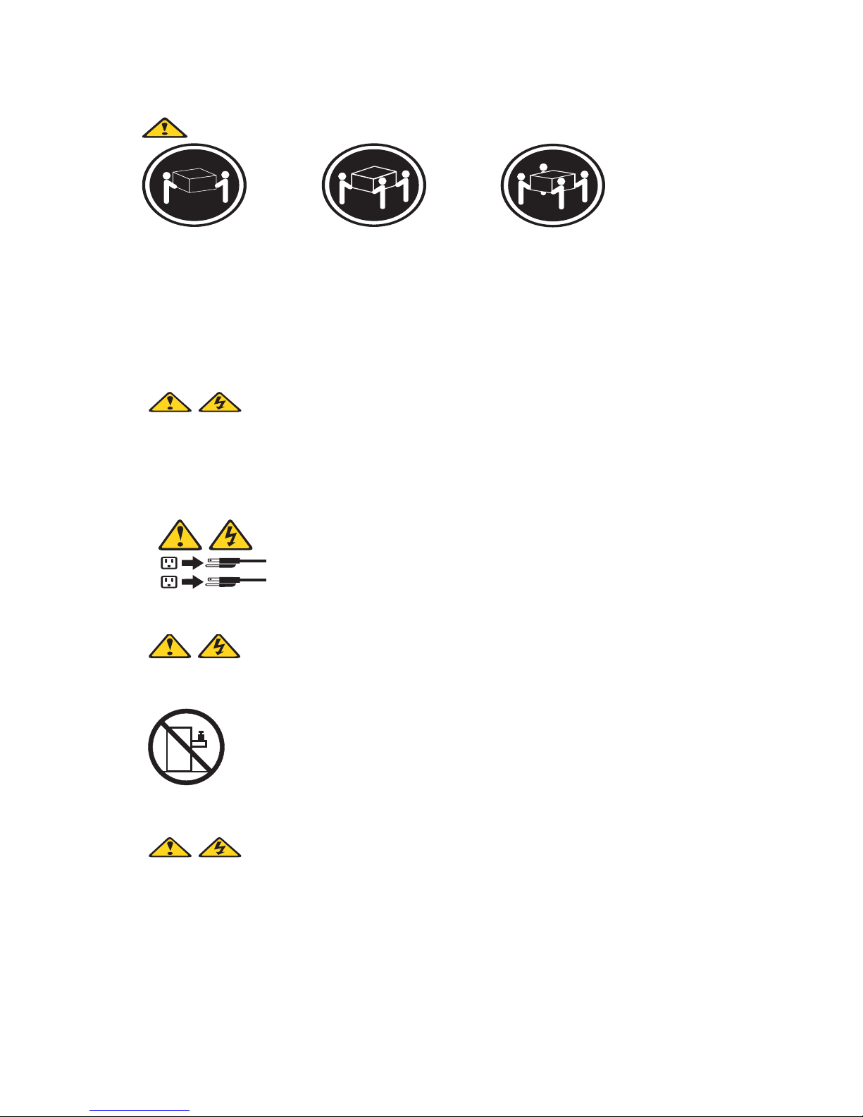
≥18 kg (37 lbs) ≥32 kg (70.5 lbs) ≥55 kg (121.2 lbs)
CAUTION:
Use safe practices when lifting.
CAUTION:
2
1
CAUTION:
The power control button on the device and the power switch on the power supply do not
turn off the electrical current supplied to the device. The device also might have more than
one power cord. To remove all electrical current from the device, ensure that all power cords
are disconnected from the power source.
Do not place any object weighing more than 82 kg (180 lbs.) on top of rack-mounted devices.
CAUTION:
Do not place any object weighing more then 82 kg (180lbs.) on top of rack-mounted devices.
x Intel Server Compute Blade SBX82 Installation and User’s Guide
Page 11
xx
xx
CAUTION:
To avoid personal injury, before lifting the unit, remove all the blades to reduce the weight.
CAUTION:
Hazardous energy is present when the blade is connected to the power source. Always
replace the blade cover before installing the blade.
Regulatory specifications and disclaimers
Safety compliance
USA: UL 60950 - 3rd Edition/CSA 22.2. No. 60950
Canada: cUL certified - 3rd Edition/CSA 22.2. No. 60950- for
Canada (product bears the single cUL mark for U.S.
and Canada)
Europe: Low Voltage Directive, 73/23/EEC
TUV/CB to EN60950 3rd Edition
TUC/CB - EMKO-TSE (74-SEC) 207/94
International: TUVCB to IEC 60950, 3rd Edition plus all
international deviations
Australia/New Zealand: CB Report to IEC 60950, 3rd Edition plus
Australia/New Zealand deviations
xi
Page 12

Electromagnetic compatibility (ECM)
USA: FCC CFR 47 Part 2 and 15, Verified Class A Limit
Canada: IC ICES-003 Class A Limit
Europe: EMC Directive, 89/336/EEC
EN55022, Class A Limit, Radiated & Conducted Emissions
EN55024 ITE Specific Immunity Standard
EN61000-4-2 ESD Immunity (Level 2 Contact Discharge, Level 3 Air Discharge)
EN61000-4-3 Radiated Immunity (Level 2)
EN61000-4-4 Electrical Fast Transient (Level 2)
EN61000-4-5 AC Surge
EN61000-4-6 Conducted RF
EN61000-4-8 Power Frequency Magnetic Fields
EN61000-4-11 Voltage Dips and Interrupts
EN6100-3-3 Voltage Flicker
Japan: VCCI Class A ITE (CISPR 22, Class A Limit)
IEC 1000-3-2 Limit for Harmonic Current Emissions
Australia/New
Zealand:
AS/NZS 3548, Class A Limit
Taiwan: BSMI Approval
Korea: RRL Approval
Russia: GOST Approval
Electromagnetic compatibility notices (USA)
This equipment has been tested and found to comply with the limits for a Class A digital device,
pursuant to Part 15 of the FCC Rules. These limits are designed to provide reasonable protection
against harmful interference when the equipment is operated in a commercial environment. This
equipment generates, uses and can radiate radio frequency energy and if not installed and used in
accordance with the instruction manual, may cause harmful interference to radio communications.
Operation of this equipment in a residential area is likely to cause harmful interference in which case
the user will be required to correct the interference at his/her own expense.
✏ NOTE
Class A device definition: If a Class A device is installed within the is system, then the
system is to be considered a Class A system. In this configuration, operation of this
equipment in a residential area is likely to cause harmful interference.
✏ NOTE
This product is intended to be installed with CAT5 cable, or equivalent, to minimize
electrical interference.
xii Intel Server Compute Blade SBX82 Installation and User’s Guide
Page 13
Electromagnetic compatibility notices (International)
Europe (CE Declaration of Conformity): This product has been tested in accordance too, and
complies with the Low Voltage Directive (73/23/EEC) and EMC Directive (89/336/EEC). The
product has been marked with the CE Mark to illustrate its compliance.
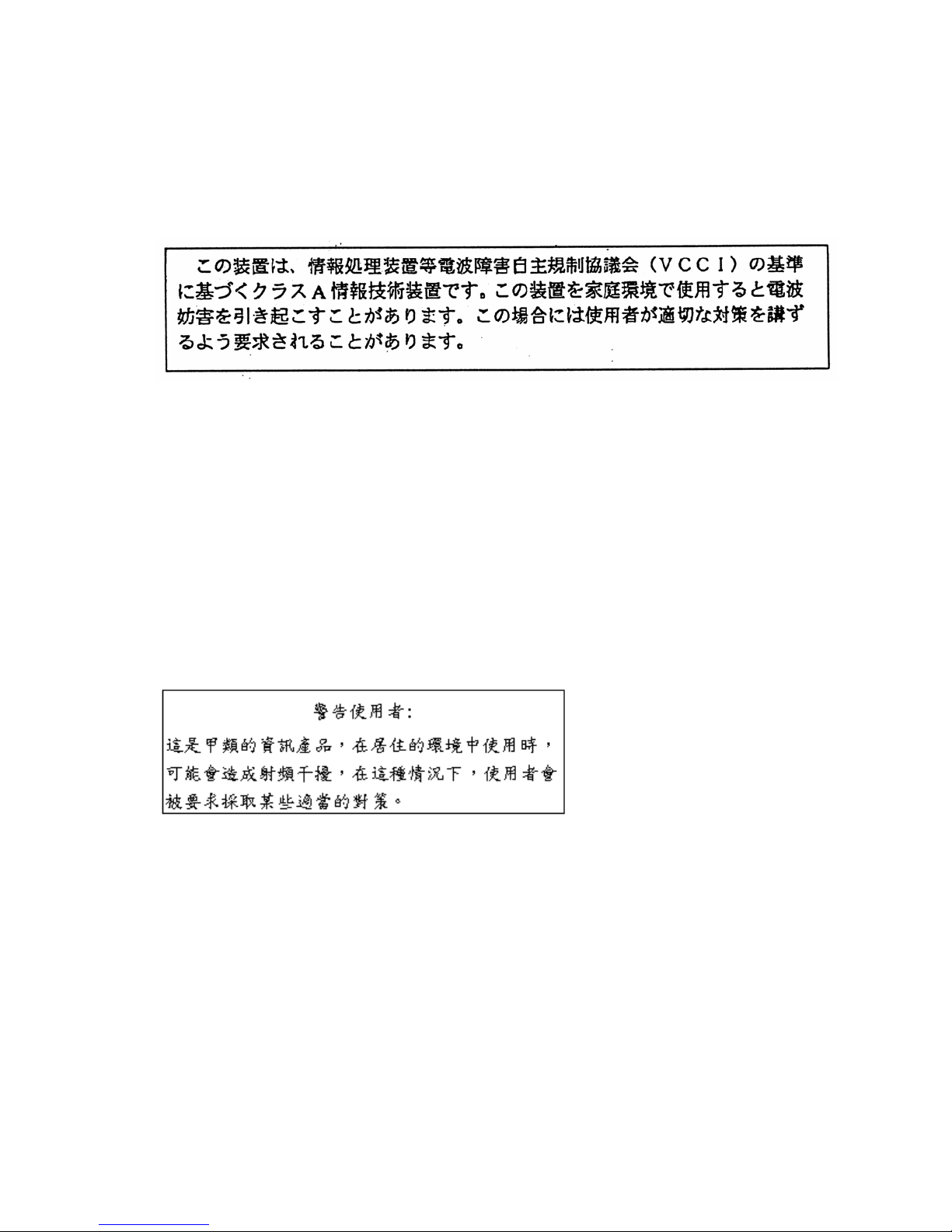
Japan EMC Compatibility:
English translation of the notice above: This is a Class A product based on the standard of the
Voluntary Control Council for Interference by Information Technology Equipment (VCCI). If this
equipment is used in a domestic environment, radio disturbance may arise. When such trouble
occurs, the user may be required to take corrective actions.
ICES-003 (Canada): Cet appareil numérique respecte les limites bruits radioélectriques
applicables aux appareils numériques de Classe A prescrites dans la norme sur le matériel brouilleur:
"Appareils Numériques", NMB-003 édictée par le Ministre Canadian des Communications.
English translation of the notice above: This digital apparatus does not exceed the Class A limits
for radio noise emissions from digital apparatus set out in the interference-causing equipment
standard entitled "Digital Apparatus," ICES-003 of the Canadian Department of Communications.
BSMI (Taiwan): The BSMI Certification number and the following warning is located on the
product safety label which is located visibly on the external chassis.
xiii
Page 14
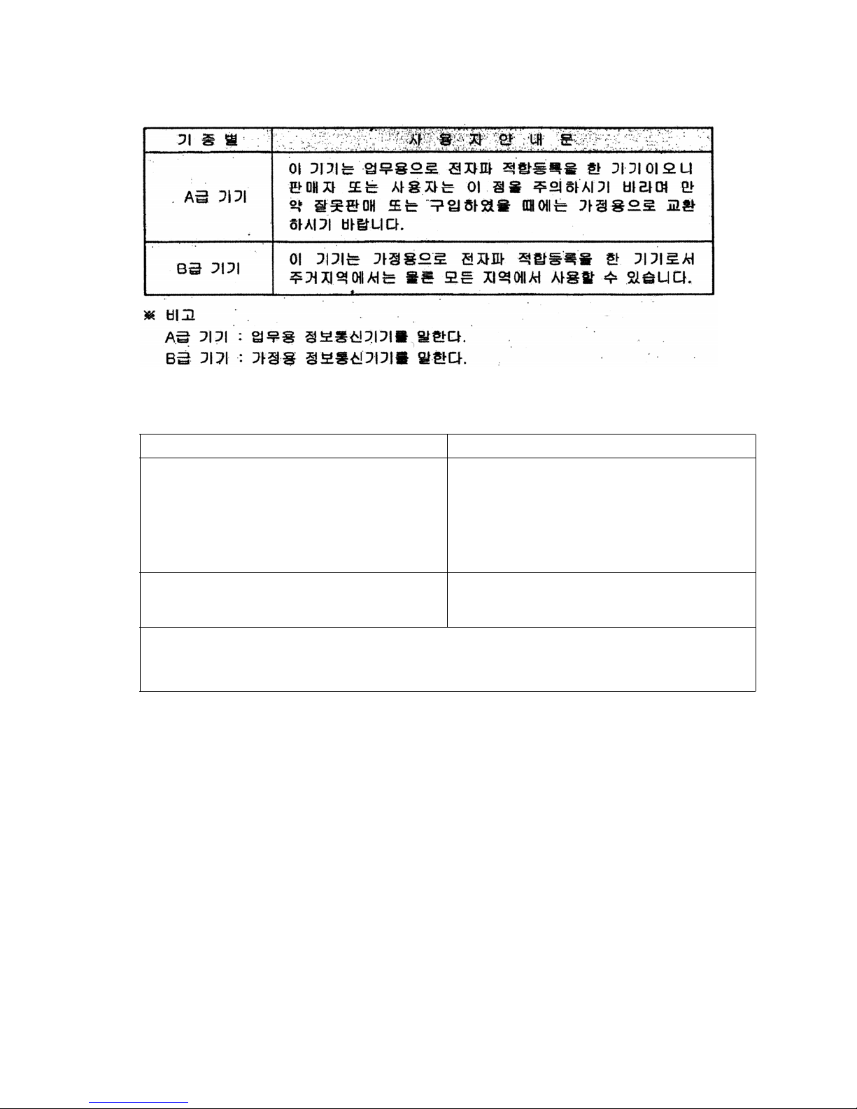
RRL Korea:
English translation of the notice above:
Device User’s Information
Class A device This device complies with RRL EMC and is operated
in a commercial environment so that distributors or
users pay attention to this point.
If this product is sold or purchased improperly, please
exchange this product to one that can be used at
home.
Class B device This device complies with RRL EMC and is operated
in a residential area so that it can be used at all other
location as well as residential area.
✏ NOTE
Class A device: operated in a commercial area. Class B device: operated in a
residential area.
xiv Intel Server Compute Blade SBX82 Installation and User’s Guide
Page 15

1 Introducing the Intel® Server Compute Blade
SBX82 blade server
These high-performance blade servers are ideally suited for networking environments that require
superior processor performance, efficient memory management, flexibility, and reliable data storage.
This Installation and User Guide provides information about:
• Setting up the blade server
• Starting and configuring the blade server
• Installing hardware options
• Installing the operating system
• Performing basic troubleshooting of the blade server
Record information about your Intel Server Compute Blade SBX82 in the following table.
✏ NOTE
The model number and serial number are on the ID label that is behind the control panel
door on the front of the blade server, and on a label on the right side of the blade server that
is visible when the blade server is not in the SBCE unit.
Product name Intel® Server Compute Blade SBX82
Product code
Model number _____________________________________________
Serial number _____________________________________________
Your Intel Server Compute Blade SBX82 will have one of the bezels shown in the following
illustration.
✏ NOTE
The illustrations in this document might differ slightly from your hardware.
1
Page 16
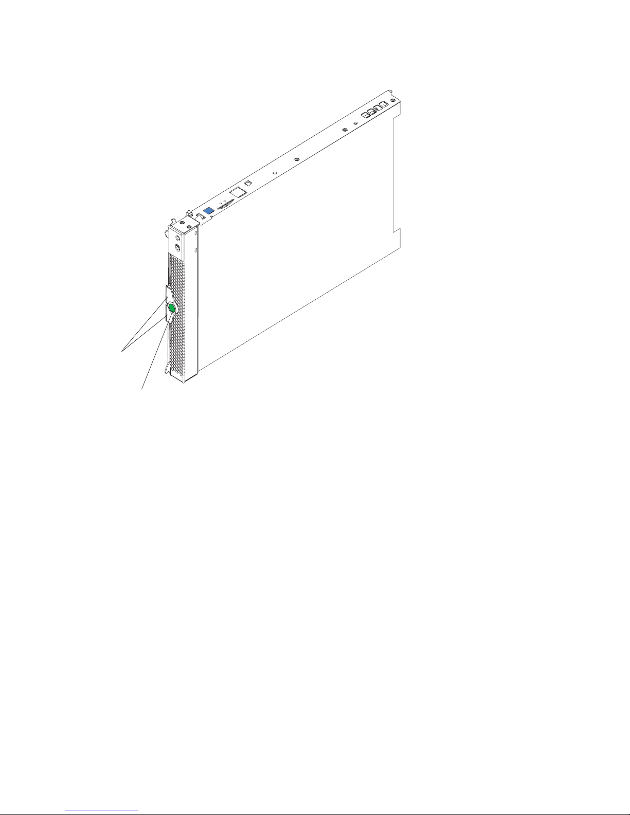
Figure 1. Blade server release levers.
Release
levers
Release
button
A set of user labels comes with the Intel Server Compute Blade SBX82. When you install the blade
server in the SBCE unit, write identifying information on a label and place the label on the SBX82
unit bezel.
Figure 2 shows the placement of the label, just below the blade server, on the SBCE unit.
2 Intel Server Compute Blade SBX82 Installation and User’s Guide
Page 17
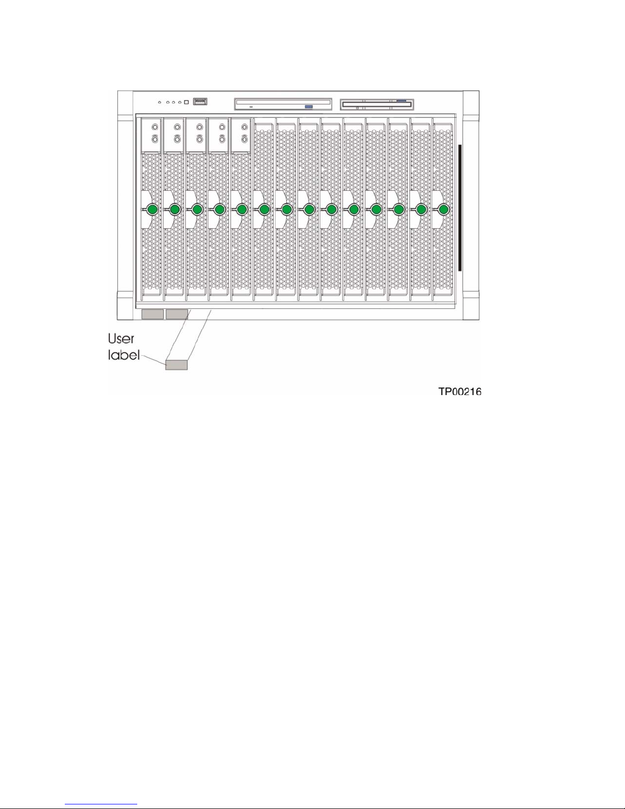
Figure 2. Label placement on the SBCE unit.
Important: Do not place the label on the blade server itself or in any way block the ventilation holes
on the blade server.
3
Page 18

Features and specifications
This section provides a summary of the features and specifications of your blade server. Use the
Configuration/Setup Utility program to determine the specific type of processor that is in the blade
server.
Reliability, availability, and serviceability features
Three of the most important features in server design are reliability, availability, and serviceability
(RAS). These RAS features help to ensure the integrity of the data stored on the blade server; that
the blade server is available when you want to use it; and that should a failure occur, you can easily
diagnose and repair the failure with minimal inconvenience.
The blade server has the following RAS features:
• Advanced Configuration and Power Interface (ACPI)
• Automatic error retry or recovery
• Automatic server restart
• Built-in monitoring for temperature, voltage, hard disk drives, and flash drives
• Chipkill* memory for DIMMs with a capacity of 512 MB or greater
• Customer upgradeable basic input/output system (BIOS) code
• Diagnostic support of Ethernet controllers
• Error codes and messages
• ECC protection on the L2 cache
• ECC memory
• Failover Ethernet support
• Hot-swap drives on optional small computer system interface (SCSI) storage expansion unit
• Light Path Diagnostics* feature
• Power-on self-test (POST)
• Predictive Failure Analysis* (PFA) alerts
• Processor serial number access
• Service processor that communicates with the management module to enable remote blade
server management
• SDRAM with serial presence detect (SPD) and vital product data (VPD)
• System error logging
• VPD (includes information stored in nonvolatile memory for easier remote viewing)
• Wake on LAN* capability
4 Intel Server Compute Blade SBX82 Installation and User’s Guide
Page 19

Intel Server Compute Blade SBX82 features
The design of your blade server takes advantage of advancements in memory management and data
storage. Your blade server uses the following features and technologies:
• Disk drive support
The blade server supports up to two 2.5-inch SCSI disk drives.
• Intel Architecture
Intel architecture technology leverages proven innovative technologies to build powerful,
scalable, reliable Intel-processor-based servers. The technology includes features such as Light
Path Diagnostics, Predictive Failure Analysis (PFA), and Advanced System Management.
• Impressive performance using the latest processor technology
Your blade server supports up to two Intel
least one processor installed; you can install an additional processor to further enhance
performance and symmetric multiprocessing (SMP) capability.
• Integrated network environment support
The blade server comes with two integrated dual Gigabit Ethernet controllers. Each Ethernet
controller has an interface for connecting to 10/100/1000-Mbps networks through an Ethernet-
compatible switch module on the SBCE unit. The blade server automatically selects between
10BASE-T and 100/1000BASE-TX environments. Each controller provides full-duplex (FDX)
capability, which enables simultaneous transmission and reception of data on the Ethernet local
area network (LAN). The controllers support Wake on LAN technology.
®
Xeon™ processors. The blade server comes with at
• I/O expansion
The blade server comes with two connectors on the system board for an optional expansion card,
such as the Intel
®
Blade Server Fibre Channel Expansion Card or the Intel® Blade Server
Ethernet Expansion Card, for adding more network communication capabilities to the blade
server.
• Large system memory
The memory bus in your blade server supports up to 8GB of system memory. The memory
controller provides support for up to four industry-standard 1.8 V, 184-pin, double-data-rate
(DDR2-400), PC3200, registered synchronous dynamic random-access memory (SDRAM) with
error correcting code (ECC) DIMMs.
• Light Path Diagnostics
The Light Path Diagnostics feature provides light-emitting diodes (LEDs) to assist in isolating
problems with the blade server. An LED on the blade server control panel is lit if an unusual
condition or a problem occurs. If this happens, you can look at the LEDs on the system board to
locate the source of the problem.
• PCI Express*
PCI Express* is a fully serial interface that can be used for universal connectivity for use as a
chip-to-chip interconnect, I/O interconnect for adapter cards, and an I/O attachment point to
Gigabit networking devices. PCI Express bridges a PCI Express bus to a PCI-X bus and converts
the transactions on the PCI bus to transactions on the PCI-X bus. Using the expansion card
connector you can add additional LAN interfaces. The expansion card connector supports PCIX 133 and bridges PCI Express into PCI-X 133.
5
Page 20

• Power throttling
Each blade server is powered by two SBCE unit redundant 2000 W power supply modules. By
enforcing a power policy known as oversubscription, the SBCE unit can load-share power
between two power modules to ensure efficient power for each device in the SBCE unit. This
policy is enforced when the initial power is applied to the SBCE unit or when a blade server is
inserted into the SBCE unit.
The possible settings for this policy are:
— Redundant without performance impact
— Redundant with performance impact
— Non-redundant
You can configure and monitor the power environment using the management module. For more
information about configuring and using power throttling, refer to your management module
manual.
Intel Server Compute Blade SBX82 specifications
The following table provides a summary of the features and specifications of the Intel Server
Compute Blade SBX82.
✏ NOTE
Power, cooling, removable-media drives, external ports, and advanced system management
are provided by the SBCE unit.
✏ NOTE
The operating system in the blade server must provide USB support for the blade server to
recognize and use the keyboard, mouse, CD-ROM drive, and diskette drive. The SBCE unit
uses USB for internal communications with these devices.
6 Intel Server Compute Blade SBX82 Installation and User’s Guide
Page 21
Processor:
Supports up to two processors
®
• Intel
• Intel
Xeon™ processors with
an 800 MHz FSB at speeds
up to 3.6GHz
®
E7520 chipset
Memory:
• Dual channel 400 MHz
(DDR2) with four DIMM slots
(8 GB maximum)
• Type: 2-way interleaved,
DDR2, PC3200, ECC SDRAM
registered x4 (Chipkill*)
DIMMs only
• Supports 256 MB, 512 MB,
1 GB, and 2 GB DIMMs (four
DIMM slots)
Service Processor:
Renassas 2166 supports:
• RS-485 interface
• Serial over LAN (SOL)
•IPMI
Drives:
Support for two internal small
form-factor SCSI drives
Size:
• Height: 24.5 cm (9.7 inches)
• Depth: 44.6 cm (17.6 inches)
• Width: 2.9 cm (1.14 inches)
• Maximum weight: 5.4 kg
(12 lb)
Integrated functions:
• Dual Gigabit Ethernet
controllers
• Expansion card interface
• BMC with IPMI firmware
• ATI* 7000M video controller
• LSI* 1020 SCSI controller
• Light Path Diagnostics
• Local service processor
• RS-485 interface for
communication with the
management module
• Four USB buses for
communication with
keyboard, mouse, diskette
drive, and CD-ROM drive
Predictive Failure Analysis
(PFA) alerts:
• Processor
• Memory
Electrical Input:
12 V dc
Environment:
• Air temperature:
— Blade server on: 10° to 35°
C (50° to 95° F). Altitude: 0
to 914 m (2998.69 ft)
— Blade server on: 10° to 32°
C (50° to 89.6° F). Altitude:
914 m to 2134 m (2998.69
ft to 7000 ft)
— Blade server off: -40° to
60° C (-40° to 140° F)
•Humidity:
— Blade server on: 8% to
80%
— Blade server off: 5% to
80%
7
Page 22
Major components of the blade server
You must remove the blade server from the SBCE unit and remove the cover to see the components.
✏ NOTE
The illustrations in this document might differ slightly from your hardware.
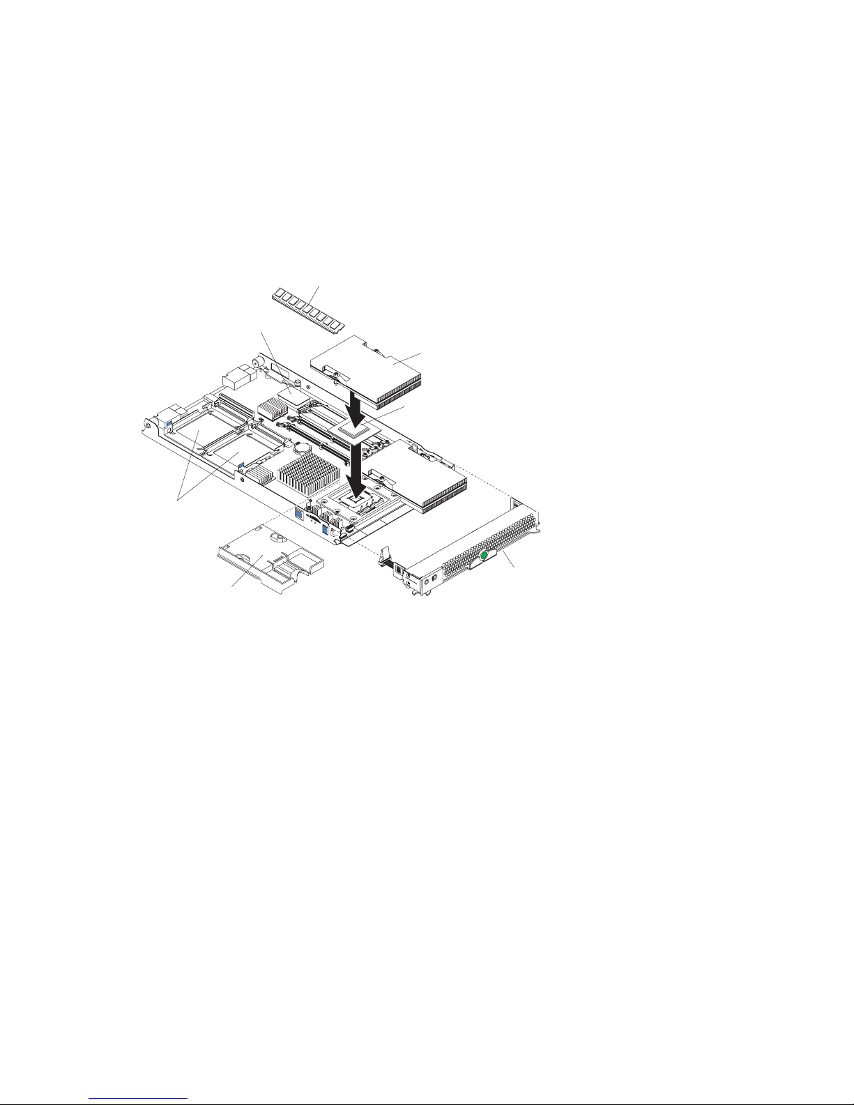
Figure 3 shows the major components of the SBX82 unit.
Figure 3. SBX82 unit major components.
DIMM
Blade expansion
unit connector
Heat sink
Processor
SCSI hard
disk drives
Bezel
Processor
heat sink filler
assembly
Related publications
In addition to this Installation and User’s Guide, the following documentation is provided in
Portable Document Format (PDF) on the Intel Server Compute Blade SBX82 Resource CD that came
with your blade server.
• Intel Server Compute Blade SBX82 Hardware Maintenance Manual and Troubleshooting Guide
This document contains information to help you solve problems yourself. It also contains
information for service technicians.
• Intel Server Compute Blade SBX82 Installation and User’s Guide
This document contains instructions for setting up and configuring the SBX82 unit and basic
instructions for installing some options. It also contains general information about the SBX82
unit.
8 Intel Server Compute Blade SBX82 Installation and User’s Guide
Page 23

Notices and statements used in this document
The following notices and statements are used in the documentation:
• Note: These notices provide important tips, guidance, or advice.
• Important: These notices provide information or advice that might help you avoid inconvenient
or problem situations.
• Attention: These notices indicate possible damage to programs, devices, or data. An attention
notice is placed just before the instruction or situation in which damage could occur.
• Caution: These statements indicate situations that can be potentially hazardous to you. A
caution statement is placed just before the description of a potentially hazardous procedure step
or situation.
• Danger: These statements indicate situations that can be potentially lethal or extremely
hazardous to you. A danger statement is placed just before the description of a potentially lethal
or extremely hazardous procedure step or situation.
9
Page 24

10 Intel Server Compute Blade SBX82 Installation and User’s Guide
Page 25

2 Using power, controls, jumpers, switches, and
indicators
This chapter describes the power features, how to turn on and turn off the blade server, what the
controls and indicators mean, and where the system board jumpers and switches are located and how
to use them.
Turning on the blade server
After you connect the blade server to power through the SBCE unit, the blade server can start in any
of the following ways:
• You can press the power-control button on the front of the blade server (behind the control panel
door) to start the server.
✏ NOTE
Wait until the power-on LED on the blade server flashes slowly before pressing the blade
server power-control button. During this time, the service processor in the management
module is initializing; therefore, the power-control button on the blade server does not
respond.
✏ NOTE
While the blade server is powering up, the power-on LED on the front of the server is lit.
See “Understanding the control panel and LEDs” on page 13 for the power-on LED states.
• If a power failure occurs, the SBCE unit and then the blade server can start automatically when
power is restored if the blade server is configured through the management module to do so.
• You can turn on the blade server remotely by means of the service processor in the management
module.
• If your operating system supports the Wake on LAN feature and the blade server power-on LED
is flashing slowly, the Wake on LAN feature can turn on the blade server, if the Wake on LAN
feature has not been disabled through the management-module Web interface.
11
Page 26

Turning off the blade server
When you turn off the blade server, it is still connected to power through the SBCE unit. The blade
server can respond to requests from the service processor, such as a remote request to turn on the
blade server. To remove all power from the blade server, you must remove it from the SBCE unit.
Shut down your operating system before you turn off the blade server. See your operating-system
documentation for information about shutting down the operating system.
The blade server can be turned off in any of the following ways:
• You can press the power-control button on the blade server behind the control panel door. See
“Understanding the control panel and LEDs” on page 13. This starts an orderly shutdown of the
operating system, if this feature is supported by your operating system.
✏ NOTE
After turning off the blade server, wait at least 5 seconds before you press the powercontrol button to turn on the blade server again.
• If the operating system stops functioning, you can press and hold the power-control button for
more than 4 seconds to turn off the blade server.
• The management module can turn off the blade server.
✏ NOTE
After turning off the blade server, wait at least 30 seconds for its hard disk drives or flash
drives to stop before you remove the blade server from the SBCE unit.
12 Intel Server Compute Blade SBX82 Installation and User’s Guide
Page 27
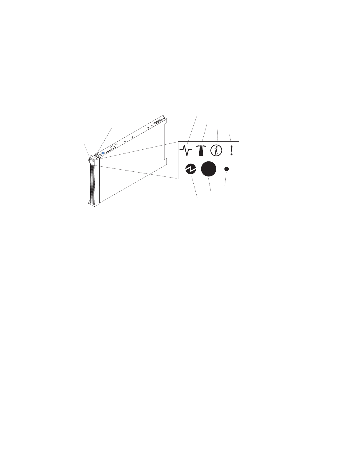
Understanding the control panel and LEDs
This section describes the controls and LEDs on your SBCE unit.
✏ NOTE
The illustrations in this document might differ slightly from your hardware.
✏ NOTE
The control panel door is shown in the closed (normal) position in the illustration. To access
the power-control button, you must open the control panel door.
CD/diskette/USB
select button
eyboard/mouse/video
elect button
Activity LED
Location LED
Information LED
Blade-error LED
NMI
Power-control button
Power-on LED
Keyboard/mouse/video (KVM) select button: Press this button to associate the keyboard port,
mouse port, and video port with this blade server. The LED on this button flashes while the request
is being processed, then is lit when the ownership of the keyboard, mouse, and video has been
transferred to this blade server. It can take approximately 20 seconds to switch the keyboard, video,
and mouse control to the blade server.
Although the keyboard that is attached to the SBCE unit is a PS/2*-style keyboard, communication
with it is through the USB. The operating system in the blade server must provide USB support for
the blade server to recognize and use the keyboard and mouse. The SBCE unit uses USB for internal
communication with these devices. When you are running an operating system that does not have
USB device drivers, such as in the following situations, the keyboard responds very slowly:
• Running the blade server integrated diagnostics
• Running a BIOS update diskette on a blade server
• Updating the diagnostics on a blade server
• Running the Broadcom firmware CD for a blade server
If there is no response when you press the keyboard/mouse/video select button, you can use the
management-module Web interface to determine whether local control has been disabled on the
blade server.
13
Page 28

You can also press keyboard keys in the following sequence to switch keyboard/mouse/video control
between blade servers:
NumLock NumLock blade_server_number Enter
Where blade_server_number is the two-digit number for the blade bay in which the blade server
is installed.
CD/diskette/USB select button: Press this button to associate the CD-ROM drive, diskette drive,
and USB port with this blade server. The LED on this button flashes while the request is being
processed, then is lit when the ownership of the CD-ROM drive, diskette drive, and USB port has
been transferred to this blade server. It can take approximately 20 seconds for the operating system
in this blade server to recognize the CD-ROM drive, diskette drive, and USB port.
The operating system in the blade server must provide USB support for the blade server to recognize
and use the CD-ROM drive, diskette drive, and USB port. The SBCE unit uses the USB for internal
communication with these devices. If there is no response when you press the CD/diskette/USB
select button, you can use the management-module Web interface to determine whether local control
has been disabled on the blade server.
Activity LED: When this green LED is lit, it indicates that there is hard disk drive, flash drive, or
network activity.
Location LED: When this blue LED is lit, it has been turned on remotely by the system
administrator to aid in visually locating the blade server. The location LED on the SBCE unit will be
lit also. The location LED can be turned off through the management-module Web interface.
Information LED: When this amber LED is lit, it indicates that information about a system error
for this blade server has been placed in the system error log. The information LED can be turned off
through the management-module Web interface.
Blade Error LED: When this amber LED is lit, it indicates that a system error has occurred in the
blade server. The blade error LED will turn off only after the error condition is corrected.
Power-on LED: This green LED indicates the power status of the blade server in the following
manner:
• Flashing rapidly: The service processor on the blade server is handshaking with the management
module.
• Flashing slowly: The blade server has power but is not turned on.
• Lit continuously: The blade server has power and is turned on.
Power-control button: This button is behind the control panel door. Press this button to turn on or
turn off the blade server.
✏ NOTE
The power-control button has effect only if local power control is enabled for the blade
server. Local power control is enabled and disabled through the management-module Web
interface.
Non-maskable interrupt (NMI) button: Press this button to start diagnostic and debugging tests.
Use the tip of a paper clip or other pointed object to reset this button.
14 Intel Server Compute Blade SBX82 Installation and User’s Guide
Page 29

System board illustration
The following illustration shows the system-board components, including connectors for userinstallable options, for the blade server.
Figure 4. System board components.
I/O expansion
option connector (J34)
I/O expansion
option connector (J131)
Blade expansion
connector (J132)
DIMM 1 (J113)
DIMM 2 (J111)
DIMM 3 (J112)
DIMM 4 (J110)
Microprocessor 1
and heatsink (U66)
Control panel
connector (J64)
(J94)
BatterySCSI connector 2
SCSI connector 1
(J95)
Microprocessor socket 2
and heatsink (U70)
Using system board switches
This section describes the system board switches on your Intel Server Compute Blade SBX82.
✏ NOTE
The illustrations in this document might differ slightly from your hardware.
Figure 5 on page 16 and Figure 6 on page 17 show the LEDs on the system board for the Intel Server
Compute Blade SBX82. Refer to Table 1 and Table 2 on page 17 for more information about the
Light Path Diagnostics LED locations and settings. Refer to these illustrations and tables when
solving problems with the blade server.
✏ NOTE
Power is available to relight the Light Path Diagnostics LEDs for a small period of time
after the blade server is removed from the SBCE unit. During that period of time, you can
relight the Light Path Diagnostics LEDs for a maximum of 25 seconds (or less, depending
on the number of LEDs that are lit and the length of time the blade server is removed from
the SBCE unit) by pressing the Light Path Diagnostics button. The Light Path Diagnostics
power present LED (CR111) lights when the Light Path Diagnostics button is pressed if
power is available to relight the blade-error LEDs. If the Light Path Diagnostics power
present LED does not light when the Light Path Diagnostics button is pressed, no power is
available to light the blade-error LEDs, and they will be unable to provide any diagnostic
information.
15
Page 30

Using switch block 2 (SW2)
You must remove the blade server from the SBCE unit, open the cover, and press the Light Path
Diagnostics button to light any error LEDs that were turned on during processing. The following
illustration and Table 1 on page 16 show the location and the settings for SW2.
Figure 5. System board switch block (SW2) location.
Switch block (SW2)
Table 1. Switch block 2 (SW2) and settings
Switch number Description
SW2 Switch block: Eight switches
• 1 - BIOS backup page jumper.
• 2 - Wake on LAN Bypass
•3 - Reserved
•4 - Reserved
•5 - Reserved
• 6 - Clear CMOS
•7 - Reserved
• 8 - Bypass power-on password
- Open: the BIOS boots from the Primary BIOS page.
- Closed: the BIOS boots from the backup BIOS page.
- Open: Enabled
- Closed: Disabled (default)
- Open: Disabled
- Closed: Enabled
- Open: Disabled (default)
- Closed: Enabled
16 Intel Server Compute Blade SBX82 Installation and User’s Guide
Page 31

Using Light Path Diagnostics to troubleshoot the system board
After the system board is removed from the chassis, you can press Light Path Diagnostics (SW4) to
troubleshoot system board component problems. See Figure 6 on page 17 and Table 2 on page 17 for
more information about locating Light Path Diagnostics LEDs and what to do if an error LED is lit.
Figure 6. Light Path Diagnostics switch (SW4) and error LEDs.
SW4
DIMM 1 error LED
DIMM 2 error LED
DIMM 3 error LED
DIMM 4 error LED
Microprocessor 1 error LED
Microprocessor 2 error LED
Table 2. SW4 Light Path Diagnostics LED locations
LED name and location Description
DIMM 1 (CR6), DIMM 2 (CR5),
DIMM 3 (CR4), DIMM 4 (CR201) error
BMC fault (CR11) There is a problem with the corresponding BMC.
Processor 1 error (CR12)
Processor 2 error (CR13)
System board fault (CR30) There is a problem with the corresponding system board.
Light Path Diagnostics LED (CR111) Lights to show the circuit is active and functioning.
There is a problem with the corresponding DIMM.
There is a problem with the corresponding processor.
Figure 7. Light Path Diagnostics switch (SW4) and error LEDs.
NMI
MIS
S BRD
TEMP
17
Page 32

Table 3. SW4 Light Path Diagnostics LED locations
LED error Action
NMI Ceck the error log for additional information. Reboot the blade
MIS Check the processors to make sure they are at the same
SBRD Reboot the blade server. If the error still exists, replace the
TEMP Check the SBCE unit blowers and air inlets. Check the room
Light Path Diagnostics LED Check the Light Path Diagnostics LED for errors
Ligh Path Diagnostics button (SW4) Press SW4 to locate faults on the system board. If the
See “Diagnosing problems using Light Path Diagnostics” on page 65 for information on what
action to take if there is a component error.
server. If the error still exists, replace the system board.
speed.
system board.
temperature.
processor or memory LED is lit, reseat the component. If the
LED remains lit, replace the defective component.
18 Intel Server Compute Blade SBX82 Installation and User’s Guide
Page 33

3 Installing options
This chapter provides instructions for installing hardware options in your blade server. Some optionremoval instructions are provided in case you need to remove one option to install another.
Installation guidelines
Before you begin installing options in the blade server, read the following information:
• Read the safety information beginning on page “Safety” on page vii and the guidelines in
“Handling static-sensitive devices.” This information will help you work safely with your blade
server and options.
• Back up all important data before you make changes to the disk drives.
• Before you remove a hot-swap blade server from the SBCE unit, you must shut down the
operating system and turn off the blade server. You do not have to shut down the SBCE unit
itself.
• Blue on a component indicates touch points, where you can grip the component to remove it
from or install it in the blade server, or open or close a latch.
• Orange on a component or an orange label on or near a component indicates that the component
can be hot-swapped, which means that if the blade server and operating system support hotswap capability, you can remove or install the component while the server is running. (Orange
can also indicate touch points on hot-swap components.) See the instructions for removing or
installing a specific hot-swap component for any additional procedures that you might have to
perform before you remove or install the component.
System reliability considerations
To help ensure proper cooling and system reliability, make sure that processor socket 2 always
contains either a processor heat sink filler or a processor and heat sink.
✏ NOTE
When using a single processor, you must install it into the CPU 1 socket.
Handling static-sensitive devices
Attention: Static electricity can damage electronic devices and your blade server. To avoid
damage, keep static-sensitive devices in their non-conductive packages until you are ready to install
them.
To reduce the possibility of damage from electrostatic discharge, observe the following precautions:
• When working on the SBCE unit, use an electrostatic discharge (ESD) wrist strap, especially
when you will be handling modules, options, and blade servers. To work properly, the wrist
strap must have a good contact at both ends (touching your skin at one end and firmly connected
to the ESD connector on the front or back of the SBCE unit).
• Limit your movement. Movement can cause static electricity to build up around you.
• Handle the device carefully, holding it by its edges or its frame.
• Do not touch solder joints, pins, or exposed printed circuitry.
19
Page 34

• Do not leave the device where others can handle and possibly damage it.
• While the device is still in its non-conductive package, touch it to an unpainted metal part of the
SBCE unit or any unpainted metal surface on any other grounded rack component in the rack
you are installing the device in for at least 2 seconds. This drains static electricity from the
package and from your body.
• Remove the device from its package and install it directly into the blade server without setting it
down. If it is necessary to set the device down, place it back into its non-conductive package. Do
not place the device on your blade server cover or on a metal surface.
• Take additional care when handling devices during cold weather. Heating reduces indoor
humidity and increases static electricity.
Installing and removing the blade server from the SBCE
unit
To install or remove a blade server from the SBCE unit, see the documentation that came with your
unit for instructions.
Opening the blade server cover
The following illustration shows how to open the cover on the blade server.
Blade-cover
release
Blade-cover
release
20 Intel Server Compute Blade SBX82 Installation and User’s Guide
Page 35

Complete the following steps to open the blade server cover:
xx
1. Read the safety information beginning on page “Safety” on page vii and “Installation
guidelines” on page 19.
2. Carefully lay the blade server down on a flat, non-conductive surface, with the cover side up.
3. Press the blade-cover release on each side of the blade server and lift the cover open, as shown in
the illustration.
4. Lay the cover flat, or lift it from the blade server and store for future use.
Statement 21:
CAUTION:
Hazardous energy is present when the blade server is connected to the power source. Always
replace the blade cover before installing the blade server.
Removing the blade server bezel assembly
To install certain options, you must first remove the blade server bezel assembly. The following
illustration shows how to remove the bezel assembly from the blade server.
Bezel-assembly
release
Bezel-assembly
release
Control panel
connector
Control-panel
cable
Complete the following steps to remove the blade server bezel assembly:
1. Read the safety information beginning on page “Safety” on page vii and “Installation
guidelines” on page 19.
2. Open the blade server cover (see “Opening the blade server cover” on page 20 for instructions).
3. Press the bezel-assembly release and pull the bezel assembly away from the blade server
approximately 1.2 cm (0.5 inch).
4. Disconnect the control-panel cable from the control-panel connector.
5. Pull the bezel assembly away from the blade server.
6. Store the bezel assembly in a safe place.
21
Page 36
Installing a SCSI hard disk drive
The blade server has two connectors on the system board for installing optional Ultra320 SCSI hard
disk drives.
Each Ultra320 SCSI connector is on the same bus. Depending on your blade server, at least one
SCSI hard disk drive might already be installed. If your blade server is equipped with one SCSI hard
disk drive, you can install an additional SCSI hard disk drive. These two SCSI hard disk drives can
be used to implement and manage a redundant array of independent disks (RAID) level-1. See
“Configuring a SCSI RAID array” on page 55 for information about SCSI RAID configuration.
Attention: To maintain proper system cooling, do not operate the system unit without a blade
server, expansion unit, or filler blade installed in each blade bay.
The following illustration shows how to install a SCSI hard disk drive and tray in the blade server.
Figure 8. Installing a SCSI drive.
Hard
drive
release
lever
SCSI ID 1
SCSI ID 0
Hard drive
release
lever
✏ Note
Do not install a SCSI hard disk drive in SCSI connector 1 (SCSI ID 1) if you intend to also install an
optional standard expansion card. The standard expansion card occupies the same area as the second
drive.
To install a SCSI hard disk drive, complete the following steps:
1. Read the safety information beginning on page “Safety” on page vii and “Installation
guidelines” on page 19.
2. Shut down the operating system, turn off the blade server, and remove the blade server from the
SBCE unit (see “Installing and removing the blade server from the SBCE unit” on page 20 for
instructions).
3. Carefully lay the blade server on a flat, non-conductive surface.
4. Open the blade server cover (see “Opening the blade server cover” on page 20 for instructions).
5. Locate SCSI connector 0 (J95).
Attention: Do not press on the top of the drive. Pressing the top could damage the drive.
22 Intel Server Compute Blade SBX82 Installation and User’s Guide
Page 37

6. Place the drive into the tray and push it, from the rear edge of the drive, into the connector until
the drive moves past the lever at the back of the tray. The drive clicks into place.
7. If you have other options to install or remove, do so now; otherwise, go to “Completing the
installation” on page 43.
Removing a SCSI hard disk drive
To remove the SCSI hard disk drive, complete the following steps:
1. Read the safety information beginning on page “Safety” on page vii and “Installation
guidelines” on page 19.
2. Shut down the operating system, turn off the blade server, and remove the blade server from the
SBCE unit (see “Installing and removing the blade server from the SBCE unit” on page 20 for
instructions).
3. Carefully lay the blade server on a flat, non-conductive surface.
4. Open the blade server cover (see “Opening the blade server cover” on page 20 for instructions).
5. Locate SCSI connector 1 and slowly pull the blue lever at the back of the hard disk drive tray to
disengage the drive from its tray.
6. From the rear edge of the drive, slide the drive out of the SCSI connector.
Attention: To maintain proper system cooling, do not operate the system unit without either a
blade server, expansion unit, or filler blade installed in each blade bay for more than 1 minute.
Installing memory modules
The following notes describe the types of dual inline memory modules (DIMMs) that the blade
server supports and other information that you must consider when installing DIMMs:
• The system board contains four DIMM connectors and supports two-way memory interleaving.
• The DIMM options that are available for your blade server are 256 MB, 512 MB, 1 GB, and
2 GB. Your blade server supports a minimum of 256 MB and a maximum of 8 GB of system
memory.
• Your blade server comes with two DIMMs in the DIMM 1 (J113) and DIMM 2 (J111) memory
connectors.
When you install additional DIMMs, be sure to install them as a pair, in DIMM connectors
3 (J112) and 4 (J110).
Install the DIMMs in the following order:
Pair DIMM connectors
First 1 (J113) and 2 (J111)
Second 3 (J112) and 4 (J110)
23
Page 38

• When you install memory, you must install a pair of matched DIMMs.
• Both DIMMs in a pair must be the same size, speed, type, and technology. You can mix
compatible DIMMs from various manufacturers.
• The second pair does not have to be DIMMs of the same size, speed, type, and technology as the
first pair.
• Install only 1.8 V, 240-pin, DDR2, PC3200, registered SDRAM with ECC DIMMs. These
DIMMs must be compatible with the latest PC3200 SDRAM Registered DIMM specification,
which is available from http://www.jedec.org/. For a current list of supported DIMMs for your
blade server, see the SBX82 Memory Qualification List.
• Installing or removing DIMMs changes the configuration information for the blade server.
Therefore, after installing or removing a DIMM, you must change and save the new
configuration information by using the Configuration/Setup Utility program. When you restart
the blade server, it displays a message indicating that the memory configuration has changed.
Start the Configuration/Setup Utility program and select Save Settings. See
“Configuration/Setup Utility menu choices” on page 49 for more information.
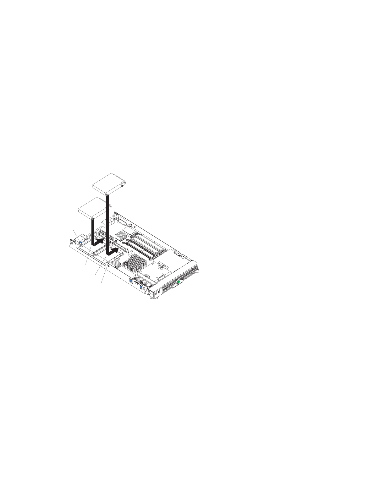
Figure 9 shows how to install DIMMs on the system board for the blade server.
Figure 9. Installing DIMMS.
DIMM slot 2 (J111)
DIMM slot 1 (J113)
DIMM slot 4 (J110)
DIMM slot 3 (J112)
Before you begin, read the documentation that comes with the DIMMs.
Complete the following steps to install a DIMM:
1. Read the safety information beginning on page “Safety” on page vii and “Installation
guidelines” on page 19.
2. Shut down the operating system, turn off the blade server, and remove the blade server from the
SBCE unit (see “Installing and removing the blade server from the SBCE unit” on page 20 for
instructions).
3. Carefully lay the blade server on a flat, non-conductive surface.
4. Open the blade server cover (see “Opening the blade server cover” on page 20 for instructions).
5. Locate the DIMM connectors on the system board. Determine the connectors into which you
will install the DIMMs.
24 Intel Server Compute Blade SBX82 Installation and User’s Guide
Page 39

6. Touch the non-conductive package that contains the DIMM option to any unpainted metal
surface on the SBCE unit or any unpainted metal surface on any other grounded rack component
in the rack you are installing the DIMM option in for at least 2 seconds. Then remove the DIMM
from the package.
7. To install the DIMMs, repeat the following steps for each DIMM that you install:
a. Turn the DIMM so that the DIMM key aligns correctly with the connector on the system
board.
Attention: To avoid breaking the retaining clips or damaging the DIMM connectors,
handle the clips gently.
b. Insert the DIMM by pressing the DIMM along the guides into the connector. Make sure the
retaining clips snap into the closed positions.
Important: If there is a gap between the DIMM and the retaining clips, the DIMM has not
been properly installed. In this case, open the retaining clips and remove the DIMM.
Reinsert the DIMM.
8. If you have other options to install or remove, do so now; otherwise, go to “Completing the
installation” on page 43.
Installing an additional processor
The blade server comes with one or two processors installed on the system board. The blade server
supports two processors. With two processors, your blade server can operate as a symmetric
multiprocessing (SMP) server. With SMP, certain operating systems and application programs can
distribute the processing load between the processors. If your blade server comes with one
processor, you can install a second processor.
Notes:
1. You can not remove the single processor and replace it with a different type of processor of
greater or lessor speed.
2. If you install a second processor, it must be of the same processor type and speed as the first
processor.
To use SMP, obtain an SMP-capable operating system.
The following notes describe the type of processor that the server supports and other information
that you must consider when installing a processor. To ensure prober blade server operation when
you install a second processor, observe the following precautions.
• Always install processors that have the same cache size and type, the same clock speed, and
identical internal and external clock frequencies (including system bus speed).
• Make sure that the processor with the lowest feature set is the startup (bootstrap) processor,
installed in the processor 1 socket (U66).
• For a list of processors that are supported by your blade server, see the SBX82 Specification
Update at the Intel Business Link (IBL).
• Thoroughly review the documentation that comes with the processor, so that you can determine
whether you have to update the blade server BIOS code. The latest level of BIOS code for your
blade server is available from IBL.
25
Page 40

• The processor sockets in this server contain built-in termination for the processor bus; therefore,
no terminator card is required if a processor socket 2 is empty. However, for proper airflow, this
socket must contain a processor heat-sink filler, sometimes called a processor baffle.
• The processor speeds are automatically set for this server; therefore, you do not have to set any
processor frequency-selection jumpers or switches.
The following illustration shows how to install the second processor on the system board for the
blade server.
Alignment marks
Heat sink filler
Heat sink
Microprocessor
Microprocessor
locking lever
Complete the following steps to install an additional processor:
1. Read the safety information beginning on page “Safety” on page vii and “Installation
guidelines” on page 19.
2. Shut down the operating system, turn off the blade server, and remove the blade server from the
SBCE unit (see “Installing and removing the blade server from the SBCE unit” on page 20 for
instructions).
3. Carefully lay the blade server on a flat, non-conductive surface.
4. Open the blade server cover (see “Opening the blade server cover” on page 20 for instructions).
5. Remove the bezel assembly (see “Removing the blade server bezel assembly” on page 21 for
instructions).
6. Locate the processor socket on the system board.
7. Remove the heat-sink filler.
8. Install the processor:
a. Remove the protective cover, tape, or label from the surface of the processor socket, if one is
present.
b. Touch the non-conductive package containing the new processor to any unpainted metal
surface on the blade server or any unpainted metal surface on any other grounded rack
component in the rack you are installing the processor in for at least 2 seconds; then remove
the processor from the package.
Attention: Do not use any tools or sharp objects to lift the locking lever on the processor
socket. Doing so might result in permanent damage to the system board.
26 Intel Server Compute Blade SBX82 Installation and User’s Guide
Page 41

c. Rotate the locking lever on the processor socket from its closed and locked position until it
stops or clicks in the fully open position (approximately a 135° angle), as shown.
Attention: You must make sure that the locking lever on the processor socket is in the fully
open position before you insert the processor in the socket. Failure to do so might result in
permanent damage to the processor, processor socket, and system board.
Lever closed
or
Lever
fully
open
Lever closed
d. Center the processor over the processor socket. Align the triangle on the corner of the
processor with the triangle on the corner of the socket and carefully press the processor into
the socket.
Attention:
• Do not use excessive force when pressing the processor into the socket.
• Make sure that the processor is oriented and aligned correctly in the socket before you
try to close the lever.
e. Carefully close the lever to secure the processor in the socket.
Lever
fully
open
27
Page 42

9. Install a heat sink on the processor:
Attention:
• Do not set down the heat sink after you remove the plastic cover.
• Do not touch the thermal grease on the bottom of the heat sink. Touching the thermal grease
will contaminate it. If the thermal grease on the processor or heat sink becomes
contaminated, contact your service technician.
Heat sink Thermal grease
a. Remove the plastic protective cover from the bottom of the heat sink.
b. Align and place the heat sink on top of the processor in the retention bracket, grease side
down. Press firmly on the heat sink.
c. Using a screwdriver, secure the heat sink to the retention bracket on the system board using
the two captive mounting screws. Press firmly on the screws and tighten them, alternating
between them. Do not overtighten the screws. If you are using a torque wrench, tighten the
screws to 8.5 to 13 Newton-meters (Nm) (6.3 to 9.6 foot-pounds).
10. If you have other options to install or remove, do so now; otherwise, go to “Completing the
installation” on page 43.
Installing an I/O expansion card
You can add I/O optional expansion cards to your blade server to give the blade server additional
connections for communicating on a network.
Attention:
When you add an expansion card, you must make sure that the I/O modules in I/O module
bays 3 and 4 on the SBCE unit both support the expansion card network-interface type. For
example, if you add an Ethernet expansion card to your blade server, the modules in I/O
module bays 3 and 4 on the SBCE unit must both be compatible with the expansion card.
All other expansion cards that are installed on other blade servers in the SBCE unit must
also be compatible with these I/O modules. In this example, you could then install two
Ethernet switch modules, two pass-thru modules, or one Ethernet switch module and one
pass-thru module. Because pass-thru modules are compatible with a variety of I/O
expansion cards, installing two pass-thru modules would enable the use of several different
types of compatible I/O expansion cards within the same unit.
28 Intel Server Compute Blade SBX82 Installation and User’s Guide
Page 43

✏ Important
Installation of a standard form-factor expansion card can require removing the SCSI drive
installed in SCSI connector 2 (J94). The standard form-factor expansion card occupies the
same space as this SCSI drive and replaces it. You cannot have a SCSI drive in SCSI
connector 2 when a standard form-factor expansion card is going to be installed. Refer to
“Removing a SCSI hard disk drive” on page 23.
If the SCSI drive that is installed in SCSI connector 2 contains any information that you
want to keep, back it up to another storage device.
If the SCSI hard disk drive that is installed in SCSI connector 2 is part of a RAID array,
delete this SCSI RAID array configuration before removing the hard disk drive. When you
delete the RAID array, the array configuration information is removed; no data is deleted.
There are two types of I/O expansion cards supported by the blade server:
• Gigabit Ethernet expansion card
• Fibre Channel expansion card
The Gigabit Ethernet and Fibre Channel expansion cards are available as a small form-factor card
and a standard form-factor card.
The following sections describe how to install an I/O expansion card in the blade server.
✏ NOTE
You cannot install both sizes of I/O expansion cards in the same blade server. You can install
the small form-factor expansion card in addition to having two SCSI hard disk drives, but
you cannot install a standard form-factor expansion card into a blade server with two SCSI
hard disk drives.
Installing a small form-factor expansion card
The small form-factor expansion option is installed near SCSI connector 2.
Complete the following steps to install the small form-factor expansion card:
1. Read the safety information beginning on page “Safety” on page vii and “Installation
guidelines” on page 19.
2. Shut down the operating system, turn off the blade server, and remove the blade server from the
SBCE unit (see “Installing and removing the blade server from the SBCE unit” on page 20 for
information).
3. Carefully lay the blade server on a flat, non-conductive surface.
4. Open the cover (see “Opening the blade server cover” on page 20 for instructions).
29
Page 44

5. Install the small form-factor I/O expansion card:
Figure 10. Installing a small form-factor I/O card in the blade server.
Expansion
Card
PR
INSTALL
ESS HE
RE
ING
W
CARD
HE
N
a. Orient the I/O expansion card as shown by number 1 in Figure 10.
b. Slide the notch at the narrow end of the card into the raised hook on the tray; then gently
pivot the card into the expansion card connectors, as shown by number 2 the illustration.
For device driver and configuration information to complete the installation of the expansion
card, see the documentation for the expansion card.
6. If you have other options to install or remove, do so now; otherwise, go to “Completing the
installation” on page 43.
30 Intel Server Compute Blade SBX82 Installation and User’s Guide
Page 45

Installing a standard form-factor expansion card
If a SCSI drive is connected to SCSI connector 0 (J94), you must remove it before you can install a
standard form-factor expansion card. You cannot have both a drive that is connected to SCSI
connector 0 and a standard form-factor expansion card installed into the blade server.
If the drive that is connected to SCSI connector 0 contains any information you want to keep, back
up the information. If the SCSI drive that is installed in SCSI connector 0 is part of a RAID array,
delete the SCSI RAID array. When you delete the array, the array configuration information is
removed. No data is deleted. After backing up the data and removing the RAID array, see
“Removing a SCSI hard disk drive” on page 23 to remove the drive.
Complete the following steps to install a standard form-factor I/O expansion card:
1. Read the safety information beginning on page “Safety” on page vii and “Installation
guidelines” on page 19.
2. Shut down the operating system, turn off the blade server, and remove the blade server from the
SBCE unit (see “Installing and removing the blade server from the SBCE unit” on page 20 for
information).
3. Carefully lay the blade server on a flat, non-conductive surface.
4. Open the cover (see “Opening the blade server cover” on page 20 for instructions).
5. If an SCSI drive is in SCSI connector 2, remove the drive and tray (see “Removing a SCSI hard
disk drive” on page 23 for instructions) (save the screws that secured the tray to the system
board); otherwise, remove the existing rear-board mounting screws (near SCSI connector 2).
6. Install the standard form-factor I/O expansion card:
Figure 11. Installing a standard form-factor expansion card in the blade server .
Expansion card
Expansion
card tray
Hard disk
drive tray
HEN
INSTALLING CARD
PRESS HEREW
31
Page 46

a. Install the expansion card tray. Secure the tray to the system board with the screws from the
option kit, as shown Figure 11.
b. Orient the expansion card and slide the notch in the narrow end of the card into the raised
hook on the tray; then gently pivot the wide end of the card into the expansion card
connectors.
✏ NOTE
For device driver and configuration information to complete the installation of the
expansion card, see the documentation for the option.
7. If you have other options to install or remove, do so now; otherwise, go to “Completing the
installation” on page 43.
IInstalling the Intel Blade Server SCSI Expansion Module
SBESCSI
The Intel® Blade Server SCSI Expansion Module SBESCSI supports up to two hot-swap SCSI hard
disk drives and up to two standard form-factor I/O cards or two small form-factor I/O cards.
To help ensure proper cooling and system reliability, make sure that:
• Each of the blade bays on the front of the SBCE unit has either a blade server or filler blade
installed.
• A removed hot-swap blade server or filler blade is replaced within 1 minute of removal.
• Each of the SCSI hard disk drive bays on the SCSI storage expansion unit contains either a hotswap SCSI hard disk drive or a filler panel.
SBCE SCSI Storage
Expansion Unit
Filler panels
Attention: Static electricity can damage electronic devices and your blade server. To avoid
damage, keep static-sensitive devices in their non-conductive packages until you are ready to install
them.
32 Intel Server Compute Blade SBX82 Installation and User’s Guide
Page 47

To reduce the possibility of electrostatic discharge, observe the following precautions:
• Limit your movement. Movement can cause static electricity to build up around you.
• Handle the device carefully, holding it by its edges or its frame.
• Do not touch solder joints, pins, or exposed printed circuitry.
• Do not leave the device where others can handle and damage it.
• While the device is still in its non-conductive package, touch it to an unpainted metal part of the
SBCE chassis for at least 2 seconds. This drains static electricity from the package and from
your body.
• Remove the device from its package and install it directly on the blade server without setting the
device down. If it is necessary to set down the device, place it back into its non-conductive
package. Do not place the device on your SBCE chassis or on a metal surface.
• Take additional care when handling devices during cold weather. Heating reduces indoor
humidity and increases static electricity.
Installing a SCSI storage expansion unit
To use SCSI hard disk drives with your blade server, you must install the Intel® Blade Server SCSI
Expansion Module SBESCSI on the blade server. You will then be able to install two 2.5-inch, hotswap, SCSI, slim-high hard disk drives in the expansion unit. The SCSI storage expansion unit can
contain up to two SCSI controllers that support embedded mirroring (RAID level-1) and embedded
mirroring with striping (RAID-1E).
✏ NOTE
After you install the SCSI storage expansion unit on your blade server, the blade server and
expansion unit together occupy two blade bays in the SBCE unit.
For a list of SCSI hard disk drives supported by your blade server, see the Tested Hardware and
Operating System List (THOL) on IBL.
Complete the following steps to install the SCSI storage expansion unit:
1. Review the information in “Safety” on page iii and “Installation guidelines” on page 19.
2. Shut down the operating system, turn off the blade server, and remove the blade server from the
SBCE unit.
3. Carefully lay the blade server on a flat, non-conductive surface.
33
Page 48

4. Remove the blade server cover:
a. Open the blade server cover and lift it from the blade server.
Blade-cover
release
Blade-cover
release
b. Store the cover in a safe place.
5. Locate the SCSI expansion connector (J132) on the system board and lift the protective film
from the connector.
Cover
pins
34 Intel Server Compute Blade SBX82 Installation and User’s Guide
Page 49
6. Install the SCSI storage expansion unit:
xx
a. Touch the non-conductive package that contains the expansion unit to any unpainted metal
surface on the SBCE chassis or any unpainted metal surface on another grounded rack
component. Then remove the expansion unit from the package.
b. Orient the expansion unit as shown in the illustration.
c. Lower the expansion unit so that the slots at the rear slide down onto the pins at the rear of
the blade server.
d. Pivot the expansion unit closed and press it firmly into place until the cover-release latches
click. The connector on the expansion unit automatically aligns with and plugs into the SCSI
expansion connector (J132) on the system board.
Statement 21:
CAUTION:
Hazardous energy is present when the blade is connected to the power source. Always
replace the blade cover before installing the blade.
7. Insert the combined blade server and expansion unit into two adjacent bays in the SBCE unit.
✏ NOTE
When any blade server or option is in blade bay 7 through 14, power modules must be
present in power bays 1, 2, 3, and 4.
8. Turn on the blade server.
9. If you have not already done so, install the LSI device drivers for your operating system.
With the expansion unit installed on your blade server, you can install up to two hot-swap SCSI hard
disk drives in the expansion unit. Each SCSI device must have a unique SCSI ID. This ID enables
the SCSI controller in the expansion unit to identify the device and ensure that different devices on
the same SCSI channel do not attempt to transfer data simultaneously. The SCSI IDs for the hard
disk drives in the expansion unit are permanent (not configurable). Table 4 lists the SCSI IDs for the
hard disk drives that are installed in the expansion unit. See “Installing a SCSI disk drive” on page
36 for instructions for installing hard disk drives.
SCSI hard disk drive 1 is in the top bay in the expansion unit; SCSI hard disk drive 2 is the bottom
bay.
Table 4. SCSI IDs for the hard disk drives in the expansion unit
Device SCSI ID
SCSI hard disk drive 1 (blade server) 0
SCSI hard disk drive 2 (blade server) 1
SCSI hard disk drive 1 (expansion unit) 2
SCSI hard disk drive 2 (expansion unit) 3
35
Page 50

✏ NOTE
You must have two SCSI drives to have a RAID-1 array or three SCSI drives to have a
RAID-1E array.
SCSI ID 7 is usually reserved for the SCSI controller; however, this SCSI ID is changeable through
the LSI configuration utility.
Use the Configuration/Setup Utility program in the blade server to enable or disable the SCSI
controller in the expansion unit. Use the LSI Logic Configuration Utility program to perform a lowlevel format on the hard disk drives, set the SCSI device scan order, or set the SCSI ID for the
controller. The LSI Logic Configuration Utility program is part of the BIOS code on the SCSI
storage expansion unit.
The expansion unit supports RAID-1E, which is an alternative to RAID-10. When the number of
SCSI hard disk drives in a RAID-1E is even, the striping pattern is identical to RAID-10. Data for a
given file may be written in stripe units to different drives in the array, rather than being written to a
single drive. By using multiple drives, the array can provide higher data transfer rates and higher I/O
rates when compared to a single large drive.
Embedded mirroring, which is also known as RAID level 1, is used when you have two hot-swap
SCSI hard disk drives installed. Each drive is an exact copy of the other. Therefore, if either drive
fails, no data is lost. When you replace a failed drive with another, the system automatically creates a
mirror copy of the functional hard disk drive on the new hard disk drive.
See “Opening the expansion unit cover” on page 38 for information about starting and using the LSI
configuration program.
Installing a SCSI disk drive
After you have installed the SCSI storage expansion unit on the blade server, you can install up to
two SCSI disk drives in the expansion unit.
If a hot-swap hard disk drive in the expansion unit fails, you can replace it without turning off the
blade server. Therefore, you have the advantage of continuing to operate your blade server while a
hard disk drive in this unit is removed or installed.
Each hot-swap drive has two indicator LEDs. If the amber hard disk drive status LED for a drive is
lit continuously, that drive is faulty and must be replaced.
Each hot-swap drive that you plan to install must be mounted in a hot-swap-drive tray. The drive
must have a Single Connector Attachment (SCA) connector. Hot-swap-drive trays come with hotswap drives.
36 Intel Server Compute Blade SBX82 Installation and User’s Guide
Page 51

The following illustration shows how to install a SCSI hot-swap hard disk drive.
Complete the following steps to install a drive in the expansion unit.
Attention: To maintain proper system cooling, do not operate the SBCE unit for more than 1
minute without either a drive or a filler panel installed in each expansion unit bay.
1. Review the information in “Safety” on page iii and “Installation guidelines” on page 19.
2. Remove the filler panel from one of the empty hot-swap bays by inserting your finger into the
depression at the top of the filler panel and pulling it away from the expansion unit.
3. Install the hard disk drive:
a. Ensure that the tray handle is open (that is, perpendicular to the drive).
b. Align the drive assembly with the guide rails in the bay.
c. Gently push the drive assembly into the bay until the drive stops.
d. Push the tray handle to the closed (locked) position.
e. Check the hard disk drive LEDs to verify that the hard disk drive is operating properly.
• If the amber hard disk drive status LED for a drive is lit continuously, that drive is faulty
and must be replaced.
• If the green hard disk drive activity LED is flashing, the drive is being accessed.
37
Page 52

xx
Opening the expansion unit cover
The following illustration shows how to open the expansion unit cover.
Cover release
(both sides)
Complete the following steps to open the expansion unit cover:
1. Read the safety information beginning on page “Installation guidelines” on page 19.
2. Carefully lay the expansion unit down on a flat, non-conductive surface, with the cover side up.
3. Press the unit-cover release on each side of the expansion unit and lift the cover open, as shown
in the illustration.
4. Lay the cover flat, or lift it from the expansion unit and store for future use.
Statement 21:
CAUTION:
Hazardous energy is present when the blade server is connected to the power source. Always
replace the blade cover before installing the blade server.
38 Intel Server Compute Blade SBX82 Installation and User’s Guide
Page 53

Installing an I/O expansion card
You can add optional I/O expansion cards to your expansion unit to give the unit additional
connections for communicating on a network.
Attention: When you add an I/O expansion card, you must make sure that the I/O modules in I/O
module bays 3 and 4 on the SBCE unit both support the I/O expansion card network-interface type.
The I/O expansion cards that are supported by the expansion unit are a standard form-factor and a
small form-factor card. The Fibre Channel expansion card and the Gigabit Ethernet expansion card
are available as small form-factor and standard form-factor I/O expansion cards.
Complete the following steps to install an I/O expansion card:
1. Read the safety information beginning on page “Safety” on page iii and “Installation guidelines”
on page 19.
2. Shut down the operating system, turn off the blade server, and remove the expansion unit from
the SBCE unit (see “Installing a SCSI storage expansion unit” on page 33).
3. Carefully lay the expansion unit on a flat, non-conductive surface.
4. Open the cover (see “Opening the expansion unit cover” on page 38 for instructions).
39
Page 54

5. Install the I/O expansion card:
Figure 12. Installing an I/O expansion card in the expansion unit.
Short card
or
Standard card
or
a. Orient the I/O expansion card, as shown in Figure 12.
b. Slide the notch in the narrow end of the card into the raised hook on the tray; then gently
pivot the wide end of the card into the I/O expansion card connectors, as shown in the
illustration.
✏ NOTE
For device driver and configuration information to complete the installation of the I/O
expansion card, see the documentation for the option.
6. If you have other options to install or remove, do so now.
40 Intel Server Compute Blade SBX82 Installation and User’s Guide
Page 55

Replacing the battery
xx
The lithium battery must be handled correctly to avoid possible danger. If you replace the battery,
you must adhere to the following instructions.
If you replace the original lithium battery with a heavy-metal battery or a battery with heavy-metal
components, be aware of the following environmental consideration. Batteries and accumulators that
contain heavy metals must not be disposed of with normal domestic waste. They will be taken back
free of charge by the manufacturer, distributor, or representative, to be recycled or disposed of in a
proper manner.
✏ NOTE
After you replace the battery, you must reconfigure your blade server and reset the system
date and time.
Statement 2:
CAUTION:
When replacing the lithium battery, use only an equivalent type battery recommended by the
manufacturer. If your system has a module containing a lithium battery, replace it only with the
same module type made by the same manufacturer. The battery contains lithium and can
explode if not properly used, handled, or disposed of.
Do not:
• Throw or immerse into water
• Heat to more than 100°C (212°F)
• Repair or disassemble
Dispose of the battery as required by local ordinances or regulations.
Complete the following steps to replace the battery:
1. Read the safety information beginning on page “Safety” on page vii and “Installation
guidelines” on page 19.
2. Follow any special handling and installation instructions that came with the battery.
3. Turn off the blade server and remove it from the SBCE unit (see “Installing and removing the
blade server from the SBCE unit” on page 20 for instructions).
4. Open the blade server cover (see “Opening the blade server cover” on page 20 for instructions).
41
Page 56

5. Locate the battery on the system board.
Figure 13. Battery location.
Battery
6. To remove the battery, use your finger to press down on one side of the battery; Then slide the
battery from the socket. The spring mechanism will push the battery out towards you as you
slide it from the socket.
7. Insert the new battery:
a. Tilt the battery so that you can insert it into the socket.
b. As you slide the battery into place, press the battery down into the socket.
42 Intel Server Compute Blade SBX82 Installation and User’s Guide
Page 57

8. Close the blade server cover (see “Closing the blade server cover” on page 45).
xx
xx
Statement 21:
CAUTION:
Hazardous energy is present when the blade server is connected to the power source.
Always replace the blade cover before installing the blade server.
9. Reinsert the blade server into the bay in the SBCE unit.
10. Turn on the blade server.
11. Start the blade server Configuration/Setup Utility program and set configuration parameters as
needed (see “Using the Configuration/Setup Utility program” on page 49 for information).
Completing the installation
To complete the installation, complete the following tasks. Instructions for each task are in the
following sections.
1. Reinstall the blade server bezel assembly, if you removed it (see “Installing the blade server
bezel assembly”).
2. Close the blade server cover, unless you installed an expansion unit option (see “Closing the
blade server cover” on page 45).
Statement 21:
CAUTION:
Hazardous energy is present when the blade server is connected to the power source.
Always replace the blade cover before installing the blade server.
3. Reinstall the blade server into the SBCE unit (see “Installing the blade server in the SBCE unit”
on page 46).
4. Turn on the blade server (see “Turning on the blade server” on page 11).
5. For certain options, run the blade server Configuration/Setup Utility program (see “Updating
your blade server configuration” on page 47).
✏ NOTE
If you have just connected the power cords of your SBCE unit to electrical outlets, you must
wait until the power-on LED on the blade server flashes slowly before pressing the powercontrol button on a blade server.
43
Page 58

Installing the blade server bezel assembly
The following illustration shows how to install the bezel assembly on the blade server.
Bezel-assembly
release
Bezel-assembly
release
Control panel
connector
Control-panel
cable
Complete the following steps to install the blade server bezel assembly:
1. Read the safety information beginning on page “Safety” on page vii and “Installation
guidelines” on page 19.
2. Connect the control-panel cable to the control-panel connector on the system board.
3. Carefully slide the bezel assembly onto the blade server, as shown in the illustration, until it
clicks into place.
44 Intel Server Compute Blade SBX82 Installation and User’s Guide
Page 59

Closing the blade server cover
Important: The blade server cannot be inserted into the SBCE unit until the cover is installed and
closed or an expansion unit is installed. Do not attempt to override this protection.
The following illustration shows how to close the blade server cover.
Cover
pins
Complete the following steps to close the blade server cover:
1. Read the safety information beginning on page “Safety” on page vii and “Installation
guidelines” on page 19.
2. If you removed the blade bezel assembly, replace it now (see “Installing the blade server bezel
assembly” on page 44 for instructions).
3. Lower the cover so that the slots at the rear slide down onto the pins at the rear of the blade
server, as shown in the illustration. Before closing the cover, check that all components are
installed and seated correctly and that you have not left loose tools or parts inside the blade
server.
4. Pivot the cover to the closed position, as shown in the illustration, until it clicks into place.
45
Page 60

xx
Installing the blade server in the SBCE unit
The following illustration shows how to install the blade server into the SBCE unit.
Complete the following steps to install a blade server in the SBCE unit:
Statement 21:
CAUTION:
Hazardous energy is present when the blade server is connected to the power source. Always
replace the blade cover before installing the blade server.
1. Read the safety information beginning on page “Safety” on page vii and “Installation
guidelines” on page 19 through “Handling static-sensitive devices” on page 19.
2. If you have not done so already, install any options that you want, such as SCSI drives or
memory, in the blade server.
3. Select the bay for the blade server.
Notes:
a. If the blade server has an expansion unit installed on it, the blade server and expansion
option require two adjacent bays.
b. When any blade server or option is in either blade bay 7 through 14 in the SBCE unit, power
modules must be present in all four power bays.
c. To help ensure proper cooling, performance, and system reliability, make sure that each of
the blade bays on the front of the SBCE unit has a blade server, expansion unit, or filler
blade installed. Do not operate the system unit without either a blade server, expansion unit,
or filler blade installed in each blade bay for more than 1 minute for the SBCE unit.
4. Make sure that the release levers on the blade server are in the open position (perpendicular to
the blade server).
46 Intel Server Compute Blade SBX82 Installation and User’s Guide
Page 61

5. Slide the blade server into the bay until it stops. The spring-loaded doors farther back in the bay
that cover the bay opening move out of the way as you insert the blade server.
6. Push the release levers on the front of the blade server closed.
7. Turn on the blade server (see “Turning on the blade server” on page 11 for instructions).
8. Make sure that the power-on LED on the blade control panel is lit continuously, indicating that
the blade server is receiving power and is turned on.
9. (Optional) Write identifying information on one of the user labels that come with the blade
servers and place the label on the SBCE unit bezel.
Refer to Figure 2 on page 3 and Figure 3 on page 8 for information about the label placement.
Important: Do not place the label on the blade server or in any way block the ventilation holes
on the blade server.
10. If you have other blades to install, do so now.
Attention: If you reinstall a blade server that you removed, you must install it into the same bay
from which you removed it. Some blade server configuration information and update options are
established according to bay number. Reinstalling a blade server into a different bay from the one
from which it was removed could have unintended consequences, and you might have to reconfigure
the blade server.
If this is the initial installation for a blade server in the SBCE unit, you must configure the blade
server with the Configuration/Setup Utility and install the blade server operating system. See
“Updating your blade server configuration” on page 47 for details.
Updating your blade server configuration
When you start your blade server for the first time after you add or remove an internal option or an
external SCSI device (if the storage expansion unit has been installed), a message might be
displayed informing you that the configuration has changed. The blade server Configuration/Setup
Utility program automatically starts so that you can save the new configuration information. See
“Using the Configuration/Setup Utility program” on page 49 for more information about the
Configuration/Setup Utility program.
Some options have device drivers that you must install. See the documentation that comes with the
option for information about installing any required device drivers.
Your blade server comes with one or two processors installed on the system board. If your blade
server comes with two processors, or if your blade server comes with one processor and you have
installed an additional processor, your blade server can now operate as an SMP server. Therefore,
you might have to upgrade your operating system to support SMP. See your operating-system
documentation for additional information.
47
Page 62

Input/output connectors and devices
The input/output connectors that are available to the blade server are supplied by the SBCE unit. See
the documentation that comes with your SBCE unit for information about the input/output
connectors.
The blade server has two selection buttons on the control panel: the CD/diskette/USB select button
and the keyboard/mouse/video select button. See “Understanding the control panel and LEDs” on
page 13 for information about these buttons and their function.
The Ethernet controllers on your blade server communicate with the network through the Ethernetcompatible switch modules on the SBCE unit. Network signals to and from the blade server or any
expansion cards are automatically routed to a same-network-interface switch module through
circuitry in the SBCE unit.
48 Intel Server Compute Blade SBX82 Installation and User’s Guide
Page 63

4 Configuring the blade server
The following configuration programs come with your blade server:
• Configuration/Setup Utility program
This is part of the basic input/output system (BIOS) code in your blade server. Use it to change
interrupt request (IRQ) settings, set the date and time, and set passwords. See “Using the
Configuration/Setup Utility program” for more information.
• LSI Logic Configuration Utility program
The LSI Logic Configuration Utility program is part of the basic input/ouput system (BIOS)
code in the blade server. Use it to set the device scan order and to set the SCSI controller IDs.
See “Using the LSI Logic Configuration Utility program” on page 56 for more information
• Preboot Execution Environment (PXE) boot agent utility program
The PXE boot agent utility program is part of the BIOS code in the blade server. Use it to select
the boot protocol and other boot options and to select a power management option. For
information about using this utility, see “Using the PXE boot agent utility program” on page 53.
Using the Configuration/Setup Utility program
This section provides the instructions for starting the Configuration/Setup Utility program and
descriptions of the menu choices.
Starting the Configuration/Setup Utility program
Complete the following steps to start the Configuration/Setup Utility program:
1. Turn on the blade server and watch the monitor screen.
2. When the message Press F1 for Configuration/Setup appears, press F1.
3. Select the settings to view or change.
Configuration/Setup Utility menu choices
The following choices are on the Configuration/Setup Utility main menu. Depending on the version
of the BIOS code in your blade server, some menu choices might differ slightly from these
descriptions.
• System Summary
Select this choice to display configuration information, including the type, speed, and cache
sizes of the processors and the amount of installed memory. When you make configuration
changes through other options in the Configuration/Setup Utility program, the changes are
reflected in the system summary; you cannot change settings directly in the system summary.
— Processor Summary
Select this choice to view information about the processors installed in the blade server.
— USB Device Summary
Select this choice to view information about the USB devices installed in the blade server
49
Page 64

•System Information
Select this choice to display information about the blade server. When you make configuration
changes through other options in the Configuration/Setup Utility program, some of those
changes are reflected in the system information; you cannot change settings directly in the
system information.
— Product Data
Select this choice to view the machine type and model of your blade server, the serial
number, and the revision level or issue date of the BIOS and diagnostics code stored in
electrically erasable programmable ROM (EEPROM).
• Devices and I/O Ports
Select this choice to view or change assignments for devices and input/output (I/O) ports.
You can also enable or disable the integrated SCSI and Ethernet controllers and all standard
ports (such as serial and parallel). Enable is the default setting for all controllers. If you disable
a device, it cannot be configured, and the operating system will not be able to detect it (this is
equivalent to disconnecting the device.)
— Remote Console Redirection
Select this choice to enable serial over LAN (SOL) and to set remote console
communication parameters.
—Video
Select this choice to view information about the integrated video controller.
— System MAC Addresses
Select this choice to set and view the MAC addresses for the Ethernet controllers on the
blade server.
•Date and Time
Select this choice to set the system date and time, in 24-hour format (hour:minute:second). This
choice is on the full Configuration/Setup Utility main menu only.
• System Security
Select this choice to set a power-on password. See “Using passwords” on page 52 for more
information about the password.
• Start Options
Select this choice to view or change the start options. Changes in the start options take effect
when you start the blade server.
— Start Sequence Options
Select this choice to view the startup device sequence that is set for the blade server.
✏ NOTE
To set the startup sequence, which is the order in which the blade server checks devices to
find a boot record, you must use the management-module Web interface.
You can set keyboard operating characteristics, such as whether the blade server starts with the
keyboard number lock on or off. You can enable the blade server to run without a diskette drive
or keyboard.
You can enable or disable the PXE option for either of the integrated Gigabit Ethernet
controllers. The default setting for this menu item is Planar Ethernet 1, which enables the PXE
option for the first Ethernet controller on the system board.
50 Intel Server Compute Blade SBX82 Installation and User’s Guide
Page 65

If you enable the boot fail count, the BIOS default settings will be restored after three
consecutive failures to find a boot record.
You can enable a virus-detection test that checks for changes in the boot record when the blade
server starts.
This choice is on the full Configuration/Setup menu only.
• Advanced Setup
Select this choice to change settings for advanced hardware features.
Important: The blade server might malfunction if these options are incorrectly configured.
Follow the instructions on the screen carefully.
— Memory Settings
Select this choice to manually enable a pair of memory DIMMs.
If a memory error is detected during POST or during memory configuration, the blade
server automatically disables the failing pair of memory connectors and continues operating
with reduced memory. After the problem is corrected, you must enable the memory
connectors. Use the arrow keys to highlight the rows representing the pair that you want to
enable; then use the arrow keys to select Enable.
To maintain optimum system operation in the event of a memory failure, you can set the
Memory Configuration for memory Mirroring or Sparing. Memory mirroring stores
duplicate data on two DIMMs to prevent data loss if a DIMM fails. Memory sparing
removes the failed memory from the system configuration and activtes a Hot Spare Memory
pair of DIMMs to replace the failed pair of DIMMs. Before you can enable memory
mirroring or sparing, at least two pairs of DIMMs must be installed in the blade server.
These pairs must adhere to the special requirements described in “Installing memory
modules” on page 23.
—CPU Options
Select this choice to disable the processor cache or to set the processor cache to use the
write-back or the write-through method. Write-back caching generally provides better
system performance
You can also select this choice to enable or disable hyper-threading and adjust the processor
performance settings. If enabled, hyper-threading will only be active if it is supported by the
operating system.
— PCI Bus Control
Select this choice to view and set interrupts for PCI devices and to configure the master
latency timer value for the blade server.
— Baseboard Management Controller (BMC) Settings
Select this choice to enable or disable the Reboot on System NMI option on the menu. If
you enable this option, the blade server will automatically restart 60 seconds after the
service processor issues a nonmaskable interrupt (NMI) to the blade server. You can also
select this choice to enable or disable and set the time-outs for the POST and OS loader
watchdog timers and view BMC version information.
– BMC Network Configuration
Select this choice to set the network addresses of the BMC.
– BMC System Event Log
Select this choice to view and clear BMC event log entries.
51
Page 66

— System Partition Visibility
Select this choice to specify whether the System Partition is to be visible or hidden.
— Integrated System Management Processor Settings
Select this choice to enable or disable the Reboot on System NMI option on the menu. If
you enable this option, the blade server will automatically restart 60 seconds after the
service processor issues a nonmaskable interrupt (NMI) to the blade server.
• Save Settings
Select this choice to save the changes you have made in the settings.
• Restore Settings
Select this choice to cancel the changes you have made in the settings and restore the previous
settings.
• Load Default Settings
Select this choice to cancel the changes you have made in the settings and restore the factory
settings.
• Exit Setup
Select this choice to exit from the Configuration/Setup Utility program. If you have not saved
the changes you have made in the settings, you are asked whether you want to save the changes
or exit without saving them.
Using passwords
From the System Security choice, you can set, change, and delete a power-on password.
If you set a power-on password, you must type the power-on password to complete the system
startup and to have access to the full Configuration/Setup Utility menu.
You can use any combination of up to seven characters (A–Z, a–z, and 0–9) for the password. Keep
a record of your password in a secure place.
If you forget the power-on password, you can regain access to the blade server through one of the
following methods:
• Remove the blade server battery and then reinstall it (see “Replacing the battery” on page 41).
• Change the position of the power-on password override switch (switch 8 on switch block 2 on
the system board) to bypass the power-on password check the next time the blade server is
turned on. You can then start the Configuration/Setup Utility program and change the power-on
password. You do not have to move the switch back to the previous position after the password is
overridden. See Figure 5 on page 16 for the location of switch block 2.
✏ NOTE
Shut down the operating system, turn off the blade server, and remove the blade server
from the SBCE unit to access the switches.
52 Intel Server Compute Blade SBX82 Installation and User’s Guide
Page 67

Using the PXE boot agent utility program
This program is a built-in, menu-driven configuration utility program that you can use to:
• Select the boot protocol and other boot options
• Select a power-management option
✏ NOTE
The RPL selection for the boot protocol option is not supported for this server.
Complete the following steps to start the PXE boot agent utility program:
1. Turn on the server.
2. When the Broadcom NetXtreme Boot Agent vX.X.X prompt appears, press Ctrl+S.
You have 2 seconds (by default) to press Ctrl+S after the prompt appears.
If the PXE setup prompt is not displayed, use the Configuration/Setup Utility program to set the
enable Ethernet PXE/DHCP option.
3. Use the arrow keys or press Enter to select a choice from the menu.
• Press Esc to return to the previous menu.
• Press the F4 key to exit.
4. Follow the instructions on the screen to change the settings of the selected items; then press
Enter.
Firmware updates
Intel will periodically make firmware updates available for your blade server. Use the following
table to determine the methods that you can use to install these firmware updates.
✏ Important
To avoid problems and to maintain proper system performance, always make sure that the blade
server BIOS, service processor, and diagnostic firmware levels are consistent for all blade servers
within the SBCE unit.
Firmware Update
diskette
Blade server
BIOS code
Blade server
diagnostic
code
Blade server
service
processor code
Ye s N o N o N o Ye s
Ye s N o N o N o Ye s
Yes Yes No No Yes
Management-
module
Web
interface
Switchmodule
Web interface
Switchmodule
Tel net
interface
Intel®
Deployment
Manager by
Veritas
OpForce
™
53
Page 68

The service processor in your blade server provides the following features:
• Continuous health monitoring and control
• Configurable notification and alerts
• Event logs that are timestamped, saved in nonvolatile memory, and can be attached to e-mail
alerts
• Remote graphics console redirection
• Point-to-point protocol (PPP) support
• Remote power control
• Remote firmware update and access to critical server settings
• Around-the-clock access to the blade server, even if the server is turned off
At some time, you might have to flash the service processor to apply the latest firmware. Download
the latest firmware for your blade server service processor from the Intel Support Web site. Use the
management-module Web interface to flash the service processor. The Web interface is described in
the Intel
®
Server Management Module SBCECMM: Installation and User’s Guide.
Configuring the Gigabit Ethernet controllers
Two Ethernet controllers are integrated on the blade server system board. Each controller provides a
1000-Mbps full-duplex interface for connecting to one of the Ethernet-compatible switch modules in
I/O module bays 1 and 2, which enables simultaneous transmission and reception of data on the
Ethernet local area network (LAN). Each Ethernet controller on the system board is routed to a
different switch module in I/O module bay 1 or bay 2. The routing from Ethernet controller to I/O
module bay will vary based on blade server type and the operating system that is installed. See
“Blade server Ethernet controller enumeration” on page 55 for information about how to determine
the routing from Ethernet controller to I/O module bay for your blade server.
You do not have to set any jumpers or configure the controllers for the blade server operating system.
However, you must install a device driver to enable the blade server operating system to address the
Ethernet controllers. For device drivers and information about configuring your Ethernet controllers,
see the Broadcom NetXtreme Gigabit Ethernet Software CD that comes with your blade server.
Your Ethernet controllers support failover, which provides automatic redundancy for your Ethernet
controllers. Without failover, you can have only one Ethernet controller from each server attached to
each virtual LAN or subnet. With failover, you can configure more than one Ethernet controller from
each server to attach to the same virtual LAN or subnet. Either one of the integrated Ethernet
controllers can be configured as the primary Ethernet controller. If you have configured the
controllers for failover and the primary link fails, the secondary controller takes over. When the
primary link is restored, the Ethernet traffic switches back to the primary Ethernet controller. (See
your operating system device driver documentation for information about configuring for failover.)
Important: To support failover on the blade server Ethernet controllers, the Ethernet switch
modules in the SBCE unit must have identical configurations to each other.
54 Intel Server Compute Blade SBX82 Installation and User’s Guide
Page 69

Blade server Ethernet controller enumeration
The enumeration of the Ethernet controllers in a blade server is operating-system dependent. You
can verify the Ethernet controller designations a blade server uses through your operating-system
settings.
The routing of an Ethernet controller to a particular I/O-module bay depends on the type of blade
server. You can verify which Ethernet controller is routed to which I/O-module bay by using the
following test:
1. Install only one Ethernet switch module or pass-thru module in I/O-module bay 1.
2. Make sure that the ports on the switch module or pass-thru module are enabled (Switch Tasks >
Management > Advanced Switch Management in the management module Web-based user
interface).
3. Enable only one of the Ethernet controllers on the blade server. Note the designation that the
blade server operating system has for the controller.
4. Ping an external computer on the network connected to the switch module. If you can ping the
external computer, the Ethernet controller that you enabled is associated with the switch module
in I/O-module bay 1. The other Ethernet controller in the blade server is associated with the
switch module in I/O-module bay 2.
If you have installed an expansion card on a blade server, communications from the option are
routed to I/O-module bays 3 and 4. You can verify which controller on the card is routed to which
I/O-module bay by performing this test, using a controller on the expansion card and a compatible
switch module or pass-thru module in I/O-module bay 3 or 4.
Configuring a SCSI RAID array
Configuring an SCSI RAID array applies to a blade server in which two SCSI hard disk drives are
installed. You can also configure a SCSI RAID array when you have a SCSI expansion unit in which
SCSI drives are installed. If you installed an expansion unit with SCSI drives installed into it, those
drives can become a part of the blade server RAID array. The expansion unit supports RAID level 1
(embedded mirroring) and RAID level 1E.
Two SCSI hard disk drives in the blade server can be used to implement and manage RAID level-1
(mirror) arrays. For your blade server, you must configure the SCSI RAID using the LSI
Configuration Utility program.
✏ Important
Depending on your RAID configuration, you must create the RAID array before you install the
operating system on your blade server.
55
Page 70

Using the LSI Logic Configuration Utility program
You can use the LSI Logic Configuration Utility to:
• Set the SCSI device scan order
• Set the SCSI ID for the controller
Complete the following steps to start the LSI configuration utility program:
1. Turn on the blade server (make sure the blade server is the owner of the keyboard, video, and
mouse) and watch the monitor screen.
2. When the <<<Press Ctrl-C to start LSI Configuration Logic
Utility>>> prompt appears, press Ctrl-C.
3. Use the arrow keys to select the controller (channel) from the list of adapters; then press Enter.
4. Follow the instructions on the resulting screen to change the settings of the selected items; then
press Enter. If you select Device Properties and Mirroring Properties, additional screens are
displayed.
56 Intel Server Compute Blade SBX82 Installation and User’s Guide
Page 71

5 Solving problems
This section provides basic troubleshooting information to help you solve some common problems
that might occur while setting up your blade server.
If you cannot locate and correct the problem using the information in this section, see the blade
server Hardware Maintenance Manual and Troubleshooting Guide on the Intel Server Compute
Blade SBX82 Resource CD.
Diagnostic tools overview
The following tools are available to help you diagnose and solve hardware-related problems:
• POST beep codes
The power-on self-test beep codes indicate the detection of a problem.
— One beep indicates successful completion of POST.
— More than one beep indicates that POST detected a problem. Error messages also appear
during startup if POST detects a hardware-configuration problem.
See “POST beep code descriptions” on page 58 and the blade server Hardware Maintenance
Manual and Troubleshooting Guide on the Intel Server Compute Blade SBX82 Resource CD.
• Troubleshooting charts
These charts list problem symptoms and steps to correct the problems. See the “Troubleshooting
charts” on page 61 for more information.
• Diagnostic programs and error messages
Real Time Diagnostics tests the major components of your SBCE unit, including the
management modules, switch modules, CD-ROM drive, diskette drive, and your blade server,
while the server operating system is running.
✏ NOTE
See the blade server Hardware Maintenance Manual and Troubleshooting Guide on the
Intel Server Compute Blade SBX82 Resource CD for more information.
• Light Path Diagnostics feature
Use the Light Path Diagnostics feature to identify system errors quickly. See the “Light path
diagnostics” on page 65 for more information.
57
Page 72

POST beep code descriptions
POST emits one beep to signal successful completion. If POST detects a problem during startup,
other beep codes might occur. Use the following beep code descriptions to help diagnose and resolve
problems that are detected during startup.
✏ NOTE
See “Diagnostics” in the blade server Hardware Maintenance Manual and Troubleshooting
Guide on the Intel Server Compute Blade SBX82 Resource CD for more information about
the POST beep codes.
One beep
Indicates successful completion of POST.
Repeating long beeps
Indicates that a memory error has occurred. Make sure that all DIMMs are correctly
installed.
One long beep and two small beeps
Indicates that a video error has occurred and the BIOS cannot initialize the monitor screen to
display additional information.
Beep codes for specific problems
Beep codes indicating specific system problems are listed in the following table.
Table 5. POST beep code descriptions
Beep code Descriptions of the POST beep codes
1-1-4 BIOS ROM checksum in-progress or failure.
Action:
1. Move the BIOS code page jumper (J12) to pins 2 and 3 to boot from the backup BIOS
code page.
2. Restart the blade server and flash the BIOS code.
3. Move the BIOS code page jumper back to pins 1 and 2 and restart the blade server.
All other
beep codes
1. Make sure that the system memory modules are installed correctly.
2. Turn off the blade server; then restart the blade server.
58 Intel Server Compute Blade SBX82 Installation and User’s Guide
Page 73

POST error messages
The following table provides an abbreviated list of the error messages that might appear during
POST. See “Diagnostics” in the blade server Hardware Maintenance Manual and Troubleshooting
Guide on the Intel Server Compute Blade SBX82 Resource CD for more information about the
POST error messages.
Table 6. Abbreviated list of POST error messages
POST message Failing device or problem found Suggested action
161 The real-time clock battery has
failed.
162 A device configuration has
changed.
Replace the battery.
Make sure that your optional devices are turned on
and installed correctly.
✏ NOTE
If you are unable to start the
Configuration/Setup Utility program, view the
system event log in the management module.
163 The time of day has not been set. Set the correct date and time.
289 A failing DIMM was disabled. Make sure that the memory is correct for your blade
server and that it is installed properly.
301
303
962 Parallel port configuration error Start the Configuration/Setup Utility program and
11xx Serial port error Make sure that the serial cable is connected correctly.
1162 Serial port configuration conflict Start the Configuration/Setup Utility program and
1800 PCI adapter hardware interrupt Start the Configuration/Setup Utility program and
Keyboard and keyboard controller • Make sure that the keyboard/mouse/video select
button LED on the front of the blade server is lit,
indicating that the blade server is connected to
the shared keyboard.
• Make sure that the keyboard cable is connected
to the SBCE unit and nothing is resting on the
keyboard keys.
make sure that the parallel-port setting is correct.
make sure that the IRQ and I/O port assignments
needed by the serial port are available.
make sure that the interrupt resource settings are
correct.
2400
2462
00019xxx Processor x is not functioning or
59
Video controller and memory • Make sure that the keyboard/mouse/video select
failed the built-in test.
button LED on the front of the blade server is lit,
indicating that the blade server is connected to
the shared monitor.
• Make sure that the monitor is connected correctly
to the SBCE unit.
Make sure that processor x is installed correctly. If the
problem remains, replace processor x.
Page 74

Table 6. Abbreviated list of POST error messages (continued)
POST message Failing device or problem found Suggested action
00180xxx A PCI adapter requested a
resource that is not available.
01295085 The blade server failed the ECC-
checking hardware test.
012980xx
012981xx
01298200 processor speed mismatch Install processors with identical speeds.
Data for processor x Download and install the latest level of BIOS code.
Start the Configuration/Setup Utility program and
make sure that the resources needed by the PCI
adapter are available.
Have the system board serviced.
I9990305 POST could not find an operating
system.
Install an operating system.
60 Intel Server Compute Blade SBX82 Installation and User’s Guide
Page 75

Troubleshooting charts
The following tables list problem symptoms and suggested solutions. See the blade server Hardware
Maintenance Manual and Troubleshooting Guide on the Intel Server Compute Blade SBX82
Resource CD for more detailed troubleshooting charts. If you cannot find the problem in these
charts, run the diagnostic programs.
Memory problems
Symptom Suggested action
The amount of system
memory displayed is less
than the amount of
physical memory installed.
Make sure that:
• The DIMMs are seated correctly.
• You have installed the correct type of memory.
• If you changed the memory, you updated the memory configuration in the
Configuration/Setup Utility program.
• All banks of memory are enabled. The blade server might have
automatically disabled a memory bank when it detected a problem, or a
memory bank might have been manually disabled.
Check the POST error log for error message 289:
• If the DIMM was disabled by a system management interrupt (SMI), replace
the DIMM.
• If the DIMMs are not installed in pairs, install DIMMs starting with DIMM 1
and DIMM 2. Make sure there is not an unpopulated DIMM slot in the
middle and make sure DIMM 3 and DIMM 4 are installed before DIMM 1
and DIMM 2
• If the system halts, make sure the DIMMs are installed in dual-ranked pairs.
Swap DIMM 3 and DIMM 4 with DIMM 1 and DIMM 2.
• If the system error indicates an unsupported memory configuration, make
sure there is more than one DIMM installed. Install DIMMs in DIMM slots 1
and 2. If this does not correct the error, replace the DIMMs flagged in the
management module log and indicated through the Light Path Diagnostics
LEDs.
• If the DIMM was disabled by the user or by POST, run the
Configuration/Setup Utility program and enable the DIMM.
• If this error remains, replace the DIMM.
Processor problems
Symptom Suggested action
The blade server emits a
continuous tone during
POST.
61
The startup (boot) processor is not working properly.
Make sure that the startup processor is seated correctly. If it is, replace the
startup processor.
Page 76

Monitor problems
✏ NOTE
The monitor screen remains blank until it is directed to a blade server that is powered on;
this is normal behavior.
Symptom Suggested action
The monitor screen goes
blank when you direct it to
a working blade server, or
it goes blank when you
start some application
programs in the blade
servers.
The screen is blank. Make sure that:
Make sure that the monitor cable is connected to the video port on the
management module.
If you still cannot find the problem, try using the monitor with another blade
server. If the problem persists, see the Intel Blade Server Chassis SBCE
Hardware Maintenance Manual and Troubleshooting Guide on the Resource CE
that came with your SBCE unit.
• The keyboard/mouse/video select button LED on the front of the blade
server is lit, indicating that the blade server is connected to the shared
monitor.
• The SBCE unit power cord is connected to the power module and a working
electrical outlet.
• The monitor cables are connected properly.
• The monitor is turned on and the brightness and contrast controls are
adjusted correctly.
Important: In some memory configurations, the 3-3-3 beep code might sound
during POST followed by a blank display screen. If this occurs and the Boot Fail
Count feature in the Start Options of the Configuration/Setup Utility program is
enabled (its default setting), you must restart the blade server three times to
force the system BIOS to reset the Configuration settings to the default
configuration (memory connector or bank of connectors enabled)
Only the cursor appears. Make sure that the keyboard, video, and mouse on the SBCE unit have not been
switched to another blade server.
The monitor has screen
jitter, or the screen image
is wavy, unreadable,
rolling, or distorted.
If the monitor self-tests show that the monitor is working correctly, consider the
location of the monitor. Magnetic fields around other devices (such as
transformers, appliances, fluorescent lights, and other monitors) can cause
screen jitter or wavy, unreadable, rolling, or distorted screen images. If this
happens, turn off the monitor.
Attention: Moving a color monitor while it is turned on might cause screen
discoloration.
Move the device and the monitor at least 300 mm (12 in.) apart, and turn on the
monitor.
✏ NOTE
To prevent diskette drive read/write errors, make sure the
distance between the monitor and diskette drives is at least 75
mm (3 in.).
Wrong characters appear
on the screen.
If the wrong language is displayed, update the firmware or operating system with
the correct language in the blade server that has ownership of the monitor.
62 Intel Server Compute Blade SBX82 Installation and User’s Guide
Page 77

Mouse problems
Symptom Suggested action
The mouse does not work. • Make sure that the keyboard/mouse/video select button LED on the front of
the blade server is lit, indicating that the blade server is connected to the
shared mouse.
• Make sure that the mouse cable is securely connected to the management
module and that the keyboard and mouse cables are not reversed.
• Make sure that the mouse works correctly with other blade servers.
• Make sure that the mouse is recognized as a USB device, not PS/2, by the
blade server. Although the mouse is a PS/2-style device, communication
with the mouse is through an internal USB bus in the SBCE unit. Some
operating systems allow you to select the type of mouse during installation
of the operating system. Select USB.
Network connection problems
Symptom Suggested action
One or more blade servers
are unable to
communicate with the
network.
Make sure that:
• The switch modules for the network interface that you are using are
installed in the correct bays and are configured and operating correctly. See
the Intel Blade Server Chassis SBCE Hardware Maintenance Manual and
Troubleshooting Guide on the SBCE unit Resource CD for details.
• The settings in the switch module are correct for the blade server (settings
in the switch module are blade server specific).
If you installed an optional expansion card, make sure that:
• The option is designed for the blade server.
• You followed the installation instructions that come with the option.
• The option is installed correctly.
• You have not loosened any other installed options or cables.
• You updated the configuration information in the Configuration/Setup Utility
program. Whenever memory or an option is changed, you must update the
configuration.
63
Page 78

Option problems
Symptom Suggested action
An option that was just
installed does not work.
Make sure that:
• The option is designed for the blade server.
• You followed the installation instructions that come with the option.
• The option is installed correctly.
• You have not loosened any other installed options or cables.
An option that used to
work does not work now.
Power problems
Symptom Suggested action
The blade server does not
turn on.
Make sure that all of the option hardware and cable connections are secure.
If the option comes with its own test instructions, use those instructions to test
the option.
1. Make sure that:
a. The power LED on the front of the SBCE unit is lit.
b. The LEDs on all the power modules are lit.
c. If the blade server or attached storage expansion unit is in blade bay 7
through 14 in the SBCE unit. Ensure power modules are installed in all
four power bays.
d. The power-on LED on the blade server control panel is flashing slowly.
• If the power LED is flashing rapidly and continues to do so, the
blade server is not communicating with the management module;
reseat the blade server and go to step 3.
• If the power LED is off, either the blade bay is not receiving power,
the blade server is defective, or the LED information panel is loose
or defective.
e. Local power control for the blade server is enabled (use the
management-module Web interface to verify), or the blade server was
instructed through the management module to turn on.
2. If you just installed an option in the blade server, remove it, and restart the
blade server. If the blade server now turns on, troubleshoot the option (see
the documentation that comes with the option for information).
3. Try another blade server in the blade bay; if it works, replace the faulty blade
server.
64 Intel Server Compute Blade SBX82 Installation and User’s Guide
Page 79

Service processor problems
Symptom Suggested action
The service processor
reports a general monitor
failure.
Shut down the operating system and turn off the blade server; then remove the
blade server from the SBCE unit, wait for 30 seconds, reinstall the blade server
in the SBCE unit, and restart the blade server.
Light path diagnostics
If the system-error LED on the system LED panel on the front or rear of the SBCE unit is lit, one or
more error LEDs on the SBCE unit components might also be lit. These LEDs help identify the
cause of the problem.
Diagnosing problems using Light Path Diagnostics
This section provides the information about using the Light Path Diagnostics to diagnose problems
that might arise during installation. To locate the actual component that caused the error, you must
locate the lit error LED on that component.
The following steps illustrate how to use the Light Path Diagnostics to diagnose a system error:
1. Shut down the operating system, turn off the blade server, and remove the blade server from the
SBCE unit.
2. Place the blade server on a flat, non-conductive surface.
3. Remove the cover from the blade server.
4. Press and hold the Light Path Diagnostics button to relight the LEDs that were lit before you
removed the blade server from the SBCE unit. The LEDs will remain lit for as long as you press
the button, to a maximum of 25 seconds.
See ’Understanding the control panel and LEDs’ on page 13 for information about the control panel
buttons and error LEDs. See ’Using Light Path Diagnostics to troubleshoot the system board’ on
page 17 See Figure 6 on page 17 for the location of the Light Path Diagnostics button and error
LEDs, then see Table 7 on page 67 for a description of the settings.
Light Path Diagnostics LEDs
The following table lists the LEDs on the Light Path Diagnostics panel, the problems they indicate,
and actions to take to solve the problems. The following illustration is the Light Path Diagnostics
key located on the system board. See Figure 6 on page 17 for more information about locating the
Light Path Diagnostics LEDs.
65
Page 80

NMI
MIS
S BRD
TEMP
Power is available to relight the Light Path Diagnostics LEDs for a short period of time after the
blade server is removed from the SBCE unit. During that time, you can relight the Light Path
DIagnostics LEDS for up to 25 seconds or less, depending on the number of LEDs that are lit and
the length of time the blade server is removed from the SBCE unit.
Light Path Diagnostics table
Use Table 7 to help determine the cause of the error and the action you should take.
Power is available to relight the Light Path Diagnostics LEDs for a small period of time after the
blade server is removed from the SBCE unit. During that period of time, you can relight the Light
Path Diagnostics LEDs for a maximum of 25 seconds (or less, depending on the number of LEDs
that are lit and the length of time the blade server is removed from the SBCE unit) by pressing the
Light Path Diagnostics button. The Light Path Diagnostics power present LED (CR111) lights when
the Light Path Diagnostics button is pressed if power is available to relight the blade-error LEDs. If
the Light Path Diagnostics power present LED does not light when the Light Path Diagnostics
button is pressed, no power is available to light the blade-error LEDs, and they will be unable to
provide any diagnostic information.
66 Intel Server Compute Blade SBX82 Installation and User’s Guide
Page 81

Table 7. Light path diagnostics
LED Problem Action
None An error has occurred and cannot
be isolated, or the service processor
has failed. The error is not
represented by a light path
diagnostic LED.
DIMM x error A memory error has occurred. Replace the failing DIMM, indicated by the lit DIMM
Check the system error log in the management
module for more information about the error.
failure LED.
Multiple DIMM LEDs do not necessarily indicate
multiple DIMM failures. If more than one DIMM LED
is lit, reseat or replace one DIMM at a time until the
error goes away. Check the system error log in the
management module for information about the
error.
Processor x
error
Temperature
error
System board
error
NMI error The system board has failed. 1. Replace the blade server cover, reinsert the
Processor
mismatch
The processor has failed. Make sure that the processor that is indicated by
the lit LED is installed correctly (see “Installing an
additional processor” on page 25 for installation
instructions).
The system temperature has
exceeded a threshold level.
The system board has failed. Replace the blade server cover, reinsert the blade
The processors do not match. Make sure that processors 1 and 2 have the same
• Determine whether a blower on the SBCE unit
has failed. If it has, replace the fan.
• Make sure that the room temperature is not too
high (see “Features and specifications” on
page 4 for temperature information).
server in the SBCE unit, and then restart the server.
blade server in the SBCE unit, and then restart
the server.
2. Check the system error log in the management
module for information about the error.
cache size and type and the same clock speed.
Internal and external clock frequencies must be
identical.
67
Page 82

68 Intel Server Compute Blade SBX82 Installation and User’s Guide
Page 83

A Getting help and technical assistance
If you need help, technical assistance, or just want more information about Intel products, you will
find a wide variety of sources available from Intel to assist you. This appendix contains information
about where to go for additional information about Intel and Intel products, what to do if you
experience a problem with your Blade server system.
Before you call
Before you call, make sure that you have taken these steps to try to solve the problem yourself:
• Check all cables to make sure that they are connected.
• Check the power switches to make sure that the system is turned on.
• Use the troubleshooting information in your system documentation, and use the diagnostic tools
that come with your system. Information about diagnostic tools is in the Hardware Maintenance
Manual and Troubleshooting Guide on the Resource CD that came with your Blade Server or
Blade Chassis.
You can solve many problems without outside assistance by following the troubleshooting
procedures in the publications that are provided with your system and software. The information that
comes with your system also describes the diagnostic tests that you can perform. Most Intel systems
and programs come with information that contains troubleshooting procedures and explanations of
error messages and error codes.
Using the documentation
Information about your Intel Server Compute Blade SBX82 is available in the documentation that
comes with your system. That documentation may include printed books, online books, readme
files, and help files. See the troubleshooting information in your system documentation for
instructions for using the diagnostic programs. The troubleshooting information or the diagnostic
programs might tell you that you need additional or updated device drivers or other software. Use
the Intel Business Link (IBL) or contact your Intel support representative to obtain the latest
technical information and download device drivers and updates.
Getting help and information from the World Wide Web
IBL includes up-to-date information about the Intel Server Compute Blade SBX82. IBL is at
http://www.intel.com/ibl. You may also find support at the Intel support site:
http://support.intel.com/support/motherboards/server/blade.htm.
69
Page 84

70 Intel Server Compute Blade SBX82 Installation and User’s Guide
Page 85

Index
B
battery
connector
15
bezel assembly
installing
removing
44
21
blade server
installing into the SBCE unit
20
blade server cover
opening
20, 38
buttons
CD/diskette/USB
keyboard/video/mouse
power-control
select
14
14
13
14
bypassing an unknown power-on password
C
components
illustrated
location of
system board
configuration
Configuration/Setup Utility
PXE Boot Agent Utility program
updating
Configuration/Setup Utility program
configuring your blade server
connectors
battery
I/O expansion card
input/output
memory
processor
SCSI
SCSI expansion
system board
controller
enable or disable Ethernet
enable or disable SCSI
Ethernet
8
8
15
49
49
47
49
49
15
15
48
15
15
15
15
15
50
50
54
52
memory
SCSI
controller enumeration
5
33, 35
55
cover
closing
45
opening
removing
20, 38
21, 38
D
daughter card
I/O expansion card
29
description
DIMM error LED
NMI button
processor error LED
17
14
17
SW2 system board switch
SW4 system board error LEDs
diagnostic tools
57
DIMM error LED
description
17
DIMM. See memory module
disk drive
support
5
drive
hot-swap, installing
37
E
environment 7
error log
entries
14
error messages, POST
59
Ethernet
controller enumeration
Ethernet controller
configuring
failover
5
54
54
redundant network connection
event log
54
F
features, blade server 5
16
17, 18
55
54
71
Page 86

filler 26
panel, hard disk drive bay
processor heat sink
forgotten power-on password, bypassing
37
19
G
Gigabit Ethernet card
I/O expansion card
29
H
handling
static-sensitive devices
hardware problems
hot-swap devices
drives
37
hot-swap drive
installing
37
57
32
I
I/O expansion card
daughter card
Gigabit Ethernet card description
installation order
memory modules
installing
bezel assembly
hot-swap drive
I/O expansion card
memory module
options
processor
SCSI hard disk drives
SCSI storage expansion unit
small form-factor expansion card
standard form-factor expansion card
installing a blade server
SBCE unit
installing a processor
notes
25
integrated functions
29
29
23
44
37
28, 39
23
19
25
22
33
29
20
7
J
jumpers
using
15
52
31
L
label placement
SBCE unit
labels
placement
LEDs
activity
information
location
power-on
system board
Light Path Diagnostics feature
Light Path Diagnostics table
load-sharing
power throttling
47
2
14
14
14
14
15
65
66
6
M
major components 8
memory
configuration changes
problems
specifications
memory module
installing
order of installation
specifications
supported
61
23
7, 23
7
5, 7
24
23
N
NMI button
description
notes
installing a processor
14
25
O
opening the blade server cover 38
option
installing
problems
order of installation
memory modules
19
64
23
P
password
72 Intel Server Compute Blade SBX82 Installation and User’s Guide
Page 87

override switch 52
power-on
placement of labels
52
2
port
input/output
48
POST (Power-on self test)
error logs
error messages
57
59
power
problem
throttling
power-on password
63, 64
6
52
Preboot eXecution Environment (PXE) option
disabling
enabling
50
50
problems
hardware
memory
monitor
mouse
option
power
processor
service processor
solving
57
61
62
63
64
64
61
65
57
processor
heat sink
installing
problem
specifications
28
25
61
7
processor error LED
description
PXE boot agent utility program
using
17
49
53
R
reliability
features
4
removing
blade bezel assembly
cover
21, 38
Ultra320 SCSI hard disk drive
21
23
S
SCSI
50
IDs
35
SCSI disk drives
support
5
SCSI hard disk drive
removing
23
SCSI RAID
configure an array
55
Server Compute Blade
specifications
6
service processor
features
54
setting
password override switch
52
small form-factor expansion card
installing
29
specifications
Server Compute Blade
6
standard form-factor expansion card
installing
start options
starting the blade server
startup sequence, setting
static electricity
31
50
11
50
19, 32
static-sensitive devices
handling
static-sensitive devices, handling
stopping the blade server
32
19
12
SW2 system board switch
description
16
switch
power-on password override
52
system board
connectors
LEDs
15
15
system board switches
using
15
system reliability
19
T
thermal material
heat sink
troubleshooting
57
charts
turning off the blade server
28
61
12
Index 73
Page 88

turning on the blade server 11
U
using
jumpers
switches
utility
Configuration/Setup Utility program
PXE boot agent program, using
15
15
49
53
74 Intel Server Compute Blade SBX82 Installation and User’s Guide
 Loading...