

Page 1

A guide for technically qualified persons
SBT2 Server Board
Quick Start Guide
Before You Begin.....................................................................2
Installation Notes
Installation Process Quick Reference...........................................4
Remove the Access Cover............................................................5
Install the I/O Shield.....................................................................6
Rearrange the Standoffs................................................................7
Install the Server Board Bumpers................................................. 8
Install the Retention Mechanisms.................................................9
Install the Server Board............................................................... 10
Install the Auxiliary Cooling Fan Brackets..................................11
Installing Processors....................................................................12
Install the Processor Termination Card........................................14
Install the Processor Cooling Epac and Auxiliary Fans............... 17
Memory.......................................................................................20
Connect Cables............................................................................21
Finish Setting up Your Chassis....................................................23
Common Problems...................................................................... 24
Jumpers ....................................................................................... 25
Server Board Components...........................................................26
Back Panel Connectors................................................................ 27
Getting Help................................................................................28
Translations of this guide are availabl e at:
Übersetzungen dieses Handbuchs sind erhältlich bei:
Versiones traducidas de esta guía se encuentran disponibles en:
Des traductions de ce guide sont disponibles à l'adresse:
Le versioni tradotte di questa Guida sono disponibili presso:
As traduções deste guia estão disponíveis em:
http://support.intel.com/support/motherboards/server/sbt2/manual.htm
Copyright © 2000 Intel Corporation. All rights reserved. No part of this document may be
copied, or reproduced in any form, or by any means without prior written consent of Intel.
Intel Corporation (Intel) makes no warranty of any kind with regard to this material, including,
but not limited to, the implied warranties of merchantability and fitness for a particular
purpose. Intel assumes no responsibility for any errors that may appear in this document.
Intel makes no commitment to update nor to keep current the information contained in this
document.
†
Third-party brands and trademarks are the property of their respective owners.
Order Number: A28558-002
Page 2

Before You Begin
Emissions Disclaimer
To ensure EMC compliance with your local regional rules and regulations, the final
configuration of your end system product may require additional EMC compliance testing.
For more information please contact your local Intel Representative.
SBT2 Server Board Product Guide
See the
compliance information. This is an FCC Class A device. Integration of it into a Class B
chassis does not result in a Class B device.
Safety Cautions
CAUTIONS
Pressing the power button does not turn off power to this board.
Disconnect the server board from its power source and from any
telecommunications l i nks, networks, or modems before doing any of
the procedures described in this guide. Failure to do this c an res ul t in
personal injury or equipment damage. Some circuitry on the s erver
board may continue to operate even t hough front panel power button
is off.
Completely close the system to the original state in which you received
it. Failure to do this c an result in personal injury, propert y and / or
equipment damage.
Read and adhere to all warnings, cautions , and notices in this gui de
and the documentation supplied wi t h the chassis, power suppl y , and
accessory modules. If the instructi ons for the chassis and power
supply are inconsist ent wi th these instructions or the instructions for
accessory modules, contact the supplier to find out how you can
ensure that your computer meet s safety and regulatory requirements.
Electrostatic di scharge (ESD) can damage server board com ponents.
Do the described procedures only at an ESD workstation. If no such
station is availabl e, you can provide some ESD protection by wearing
an antistatic wrist strap and attaching it to a metal part of the comput er
chassis.
for product Safety and EMC regulatory
2 SBT2 Server Board Quick Start Guide
Page 3

Items Provided on the Bootable CD-ROM
SBT2 Server Board Product Guide
®
SC5000 Server Chassis Subassembly Product Guide
Intel
Software drivers and utilities
To view the product guides, boot to W indows† 95/Windows NT†/
†
Windows 98/Windows 2000 and use Adobe
Acrobat†.
Safety and Regulatory Compliance
See the SBT2 Server Board Product Guide for pr oduct Safety and EMC
regulatory compliance informat ion.
Intended uses: This product was evaluated for use in servers that will be
installed in offices, computer rooms, and similar locations. Other uses r equire
further evaluation.
EMC testing: Before computer integration, make sure that the chassis, power
supply, and other modules have passed EMC testi ng using a server board with a
microprocessor from the same family (or higher) and operating at the same (or
higher) speed as the microprocessor used on this server board.
Server board diagram label provided: Place the label i nsi de the chassis in an
easy-to-see location, preferably oriented similarly to the server board.
I/O panel label provided: Place the label on the I/O shield. The cut outs are for
the top serial port and the parallel port.
Minimum Hardware Requirements
To avoid integration difficulties and possible board damage, your system must
contain the following minimum re quirements. For a list of qualified memory
and chassis components see
http://support.intel. com/support/motherboards/server/SBT2/compa t.htm
Processor
Minimum of one Intel
®
Pentium® III XeonTM processor and a processor
termination card. The SBT2 server board only supports processors with the
following product codes: BX80526KB866256, B X 80526KB001256,
BX80526KB933256.
Memory
Minimum of 64 MB of 133 MHz, 3.3 V, PC/133 compliant registered SDRAM
on 168 pin gold DIMMs.
Power Supply
Minimum of 350 W with 0.8 A +5 V standby current (in order to support
†
Wake On LAN
(WOL)). You must provide standby curre nt, or the board will
not boot.
SBT2 Server Board Quick Start Guide 3
Page 4

Installation Notes
Before installing the SBT2 ser ver board into your chassis, you must install the
processor retention mechanisms. The NIC LED, HD activity LED, and NMI
switch on the SC5000 front panel do not function with the SBT2 server board.
Installation Process Quick Reference
Where the
Step
Remove the access cover This guide
Install the I/O shield This guide
Install the server board bumpers This guide
Rearrange the standoffs This guide
Install the process or retention mechanisms This guide
Install the server board This guide
Install the auxiliary cooling fan brackets This guide
Install the primary proc essor This guide
Install the process or termination card (or second
processor)
Install the process or cooling epac and fans This guide
Install memory This guide
Connect cables to the server board This guide and the
Finish setting up your chassis (start with “Install
the Diskette Drive”)
information is located
This guide
SC5000 Product Guide
SC5000 Product Guide
4 SBT2 Server Board Quick Start Guide
Page 5

Remove the Access Cover
Facing the front of the chassis, the access cover is on the right side for pedest almounted (tower) servers, and on the top for rack- mounted servers.
1 Loosen the captive thumbscrews that secure the access cover in place.
2 Slide the cover backward a short distance, until it stops.
3 Pull the entire cover outward, straight away from the chassis, to disengage
the rows of tabs from the notches in the top and bottom edges of the
chassis. Set the cover aside.
OM09083
SBT2 Server Board Quick Start Guide 5
Page 6

Install the I/O Shield
✏ NOTE
An ATX 2.03-compliant I /O shield is provided with the server board. The
shield is required by Elec t rom agnetic Interference (EMI) regulations to
minimizes EMI. If the shield does not fit the chassis, obtain a properly
sized shield from the chassis supplier.
The shield fits the rectangular openi ng near the power supply in the back of
the chassis. The shield has cutouts that match the I/O ports.
1 Install the EMI gasket on the I/O shield. Peel the paper strip off of the
adhesive on the EMI gasket. Place the gasket on the board side of the I/ O
shield (the side with the metal fingers). Make sure the holes in the EMI
gasket line up with the holes in the I/O shield.
2 Install the shield from inside the chassis. Orient the shield so that the
cutouts align with the corresponding I/ O connectors on the server board.
Make sure the metal fingers are on the inside of the chassis.
3 Position one edge so that the dotted groove is outside the chassis wall, and
the lip of the shield rests on the inner chassis wall.
4 Hold the shield in place, and push it into the opening until it is seated.
Make sure the I/O shield snaps into place all the way around.
OM10628
5 Place the I/O label on the I/O shield. The cut out s on the label are for the
top serial port and the parall el port.
6 SBT2 Server Board Quick Start Guide
Page 7
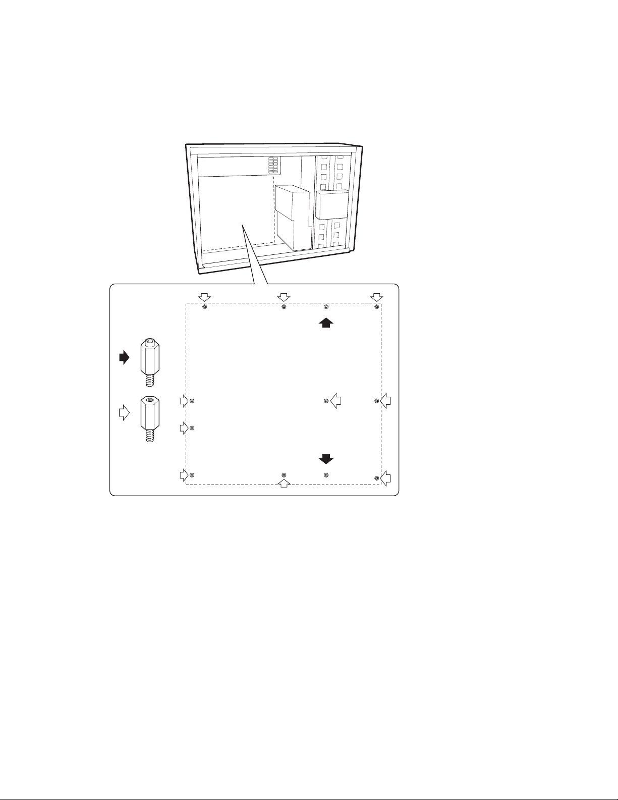
Rearrange the Standoffs
The standoffs in the chassis must be installed in screw holes
1,4,5,6,7,13,17,18,19,20,23,26. The hole numbers are stamped i n the chassis
sheet metal. Make sure the two posit ioning standoffs are in holes 17 and 19.
Failure to properly rearrange the metal standoffs may cause the server board to
malfunction and may permanently damage the server board.
171720
=
4
=
5
61319
18
23
26
OM10429
SBT2 Server Board Quick Start Guide 7
Page 8
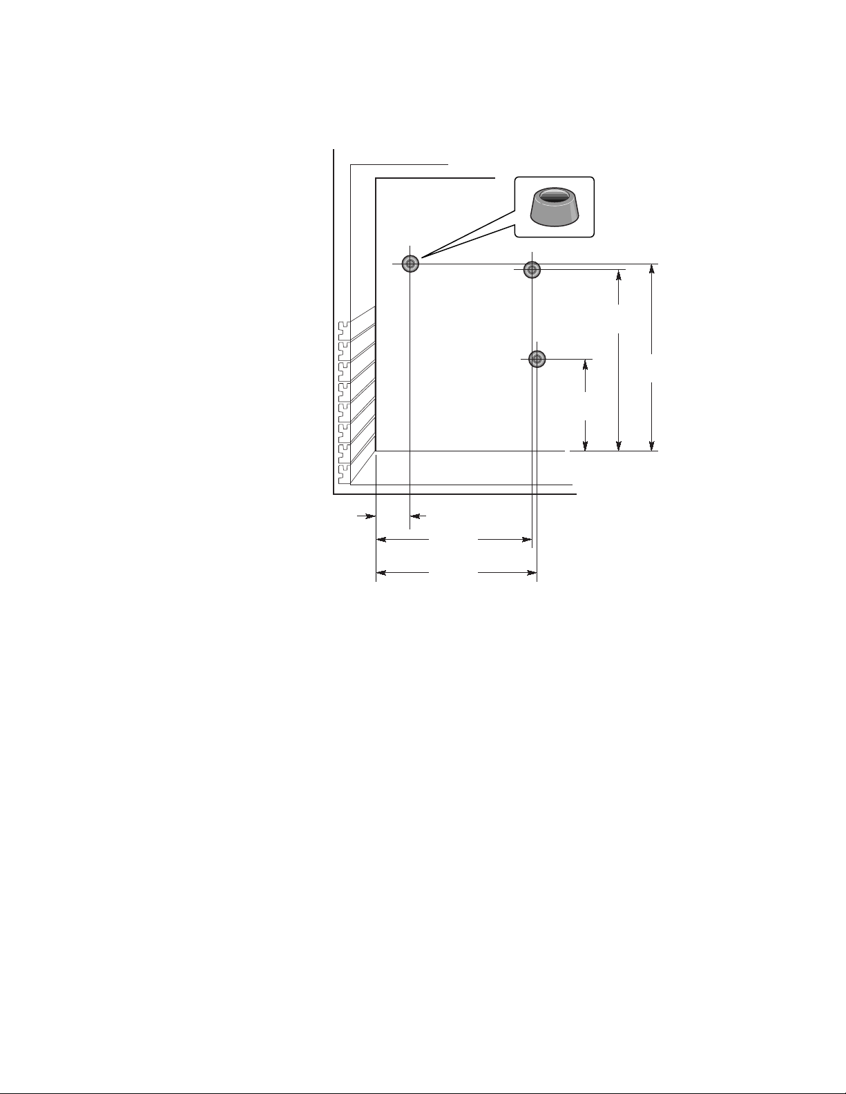
Install the Server Board Bumpers
Peel the adhesive backing from three rubber bumpers; stick the bumpers to the
chassis wall.
8.375
[212.72]
8.750
[222.25]
4.250
[107.95]
1.625
[41.27]
7.250
[184.15]
7.500
[190.50]
OM10422
8 SBT2 Server Board Quick Start Guide
Page 9

Install the Retention Mechanisms
The retention mechanism assembly consists of two plastic retention
mechanisms that go on the top of the server board, two steel stiffeners that go
underneath the board, and two plastic insulators that go between the steel
stiffeners and the server board.
Install the retention mechanism on the server board before installing the board
in the chassis.
1 Lay one steel stiffener (D) down on your work surface. Place one plastic
insulator (C) on top of it. Position the server board (B) over the stiffener
and insulator so the screw holes in the server board, insulator, and the
stiffener line up.
2 Place one plastic retention mechanis m (A) on the top of the server board.
A
E
B
C
D
OM10414
3 Insert and tighten two screws to hold all the pieces in place.
4 Place the second stiffener and insulator on your work surface. Position the
server board over the stiffener and insulator so the screw holes line up.
5 Insert and tighten two screws to hold all the pi eces in place.
6 Place the second plastic retention mechanis m in place. Insert and tighten
four screws to hold it in place.
SBT2 Server Board Quick Start Guide 9
Page 10
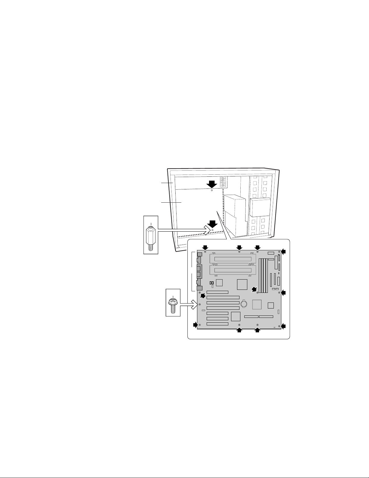
Install the Server Board
The screws for installing the server board are shipped with the chassis. You
may need to move cables out of the way to properly install your server board.
1 Remove the top piece of foam epac from the system fans.
2 Tilt the board into the chassis I/O connector end first. Position the board
so the screw holes line up with the standoffs. There are two positioning
standoffs (D) that extend into the holes on the server board. These two
standoffs will help you position the board correctly. Make sure the I/O
connectors stick out through the I/O shield. Look through the holes in the
I/O shield to make sure that the metal tabs on the I/O shield are on top of
the USB and NIC connectors, not inside.
3 Insert one screw through one of the mounting hol es of the board and into a
threaded standoff. Do not tighten the screw until the next step.
4 Insert the remaining screws through the mounting holes and into the
threaded standoffs. Make sure the board is properly seated, then tight en all
the screws firmly, starting with the screws in the center of the board.
A
B
D
C
E
D
D
OM10427
10 SBT2 Server Board Quick Start Guide
Page 11
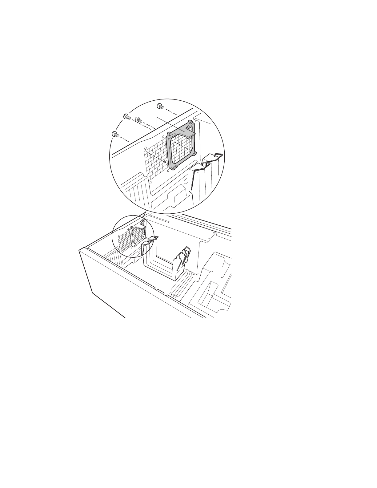
Install the Auxiliary Cooling Fan Brackets
1 Place one fan bracket into the chassis as shown in the illustration. Make
sure the screw holes in the bracket line up with the screw hole in the
chassis.
2 Insert and tighten four screws to hold the bracket in place.
3 Repeat for the second fan bracket.
A
OM10418
SBT2 Server Board Quick Start Guide 11
Page 12
Installing Processors
✏ NOTE
The SBT2 server board only support s processors with the f ol l owi ng order
numbers: BX80526KB866256, B X 80526KB001256, BX80526KB933256.
If you are installing only one processor, you must install a termination card in
the secondary processor slot.
1 Observe the safety and ESD precautions at the beginning of this document.
2 Clip two plastic ejectors (A) to the processor (B).
A
B
C
D
OM10413
3 Slide the processor into the primary processor slot (slot closest to power
supply). Push down firmly, wi th even pressure on both sides of the top,
until the processor is seated in the processor connector on the server board.
12 SBT2 Server Board Quick Start Guide
Page 13
4 Move the retention wires over the plastic ejectors to hold the processor in
place.
A
B
OM10415
5 After you have installed the processor(s ), you must configure the speed
jumpers. See the CPU Clock Speed table on page 25.
6 Repeat for the second processor. If you are installing two processors, skip
the section titled “Install the Processor Termination Card.”
SBT2 Server Board Quick Start Guide 13
Page 14

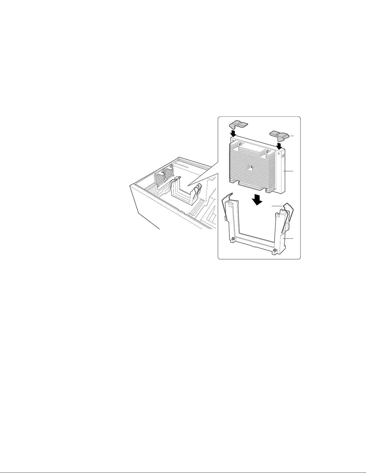
Install the Processor Termination Card
If you are installing only one processor, you must install a termination card in
the secondary processor slot. For proper cooli ng you must install the air baffle
on the termination card.
1 For easier assembly of the air baffle, prefold all of the folds.
A
C
B
A
B
OM10621
2 Fold the sides of the air baffle up. Fold the bottom the ai r baffle up. Insert
the tabs from the outside into the slots (A).
3 Fold the top of the air baffle up. Insert the tabs from the outside into the
slots (B).
4 Fold the back of the air baffle over (C).
14 SBT2 Server Board Quick Start Guide
Page 15
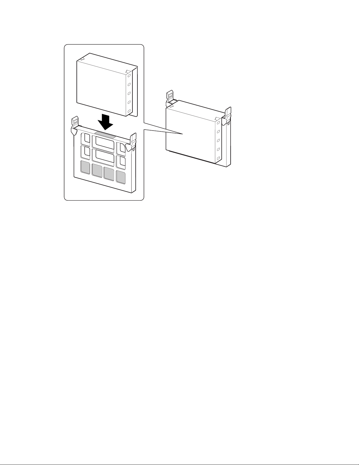
5 Slide the air baffle over the termination card assembly.
OM10620
SBT2 Server Board Quick Start Guide 15
Page 16

6 Slide the termination card int o t he secondar y pr ocessor slot. Make sure the
air baffle fits inside the retention mechanism. Push down firmly, with
even pressure on both sides of the top, until the card is seated in the
processor connector on the server board. See Server Board Components
on page 26 for the location of the secondary processor slot.
B
A
C
D
OM10619
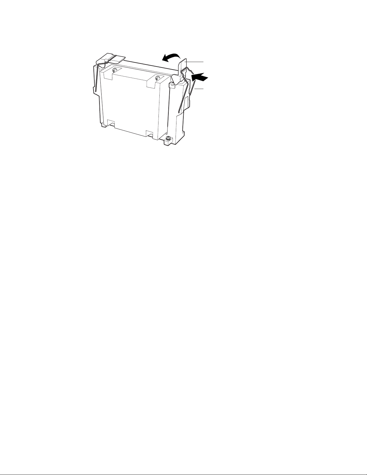
7 Move the retention wires over t he pl astic ejectors to hold the processor in
place. Make sure the air baffle is inside the retention mechanism and is
flush against the termination card.
B
A
OM10618
16 SBT2 Server Board Quick Start Guide
Page 17

Install the Processor Cooling Epac and Auxiliary Fans
1 Connect the fan cables to the server board. Do not install the fans in their
brackets yet. Let the fans lie on the PCI slots.
P9 P10
A
1 1
OM10421
SBT2 Server Board Quick Start Guide 17
Page 18
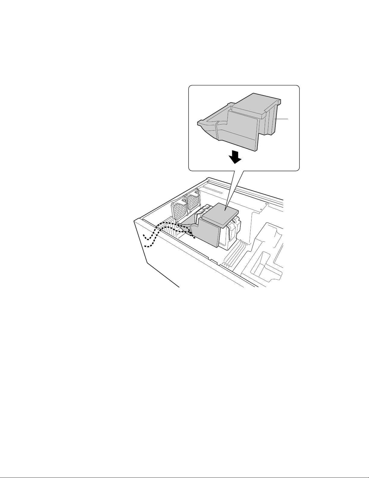
2 Place the bottom piece of epac into the chassis as shown. Make sure it is
fully seated in the chassis. If it isn’t, the cover will not fit properly.
✏ NOTE
The epac drops straight in. Do not tilt it in; tryi ng t o straighten in will
break the epac.
A
OM10425
18 SBT2 Server Board Quick Start Guide
Page 19

3 Clip the fans into place. Make sure that the label on the fan faces the ai r
holes in the chassis (away from the processors).
A
OM10419
SBT2 Server Board Quick Start Guide 19
Page 20

Memory
Only PC133-compliant SDR A M is supported by the server board. Install from
64 MB to 4 GB of registered memory, using up to four single- or doublebanked DIMMs.
DIMMs must be installed in order from slot 1 to slot 4, no empty slots betw een
installed DIMMs. Slot 1 is the slot farthest from t he pr ocessors.
Installed DIMMs must be the same speed and must all be registered. For a list
of supported memory, call your service r e presentative or visit the Int e l Support
website:
http://support.intel.com/support/motherboards/server/SBT2/compat.htm
214
3
OM10426
20 SBT2 Server Board Quick Start Guide
Page 21

Connect Cables
See Server Board Components for connector locat ions.
1 Connect the front panel cable to the SSI connector on the front panel and
the reset (1M7), P26, and P27 connectors on the server board. Remove the
chassis intrusion switches from the chassis and install the switches
attached to the front panel cable.
A
B
B
A
OM10601
SBT2 Server Board Quick Start Guide 21
Page 22

2 Place the top piece of foam epac into the chassis as shown.
A
OM10420
22 SBT2 Server Board Quick Start Guide
Page 23

3 Connect the main chassis fans to the fan connectors on the hot swap
backplane. You will need to remove the bottom fan from the epac and
rotate it so the fan cable will reach the connector on the hot swap bay.
A
B C
OM10602
4 Connect the speaker cable to the connector on the server board (P25).
5 Connect the hot swap SCSI cable to the LVD SCSI connector on the
server board.
Finish Setting up Your Chassis
You are now ready to install drives into your chassis. Start at the section titled:
®
“Install Diskette Drive” in the Intel
SC5000 Server Chassis Subassembly
Product Guide. We recommend you install any drives before connecting their
data cables to the server board. Connect the floppy cable to the server board
before you connect the IDE cable.
There is only one IDE connector on the SBT2 server board, you must route the
cable to either the top drive bays or the bottom drive bays. The cable is not
long enough to reach both. Connect the blue connector on the cable to the
server board. Pin one (the red stripe on the cable) is oriented the same as the
floppy connector. Since the IDE cable is not keyed, use the floppy cable as a
reference.
SBT2 Server Board Quick Start Guide 23
Page 24

Common Problems
The system does not boot or show vid e o at power on.
• If configuring with only one processor verify that the processor is in the
Primary Processor slot and the termination card is in the Secondary
Processor slot. (See the server board components diagram on page 26).
• Beep code 1-3-3-1 means you have unrecognized or bad memory. Remove
DIMMs one at a time to isolat e which one is causing problems.
• Your power supply must provide 0.8 A of +5 V St andby current to support
WOL. If the standby current is not present, your board will not boot.
The reset button does not work.
• You may have installed the reset cable backwards. Turn of f your system,
open the chassis, unplug the reset cable from the server board, turn it
around, and plug it back in. Then close your system and turn it on.
The system sometimes works, but is exhibiting erratic behavior.
• This is typically the r esult of using a under-powered power supply. M a ke
sure it’s at least a 350 W power supply.
24 SBT2 Server Board Quick Start Guide
Page 25

Jumpers
7C10
87
65
43
1
2
CPU Clock Speed (7C10)
CPU Speed Pin 1-2 Pins 3-4 Pins 5-6 Pins 7-8
866
900
1000
ää
ää
ä
Configuration Jumper (3N7)
Jumper
Name Pins What it does at system reset
Configuration
Jumper
BIOS
Recovery
Reserved 7-8 Reserved. These pins shoul d not be
Reserved 5-6 Reserved. These pins shoul d not be
Password
Disable
CMOS clear 1-2 If these pins are jumpered, the CMOS
11-12 Normal operation. These pins should
always be jumpered.
9-10 For normal operation, these pins s houl d
not be jumpered.
jumpered.
jumpered.
3-4 If these pins are jumpered, the password
will be cleared on the next reset. These
pins should not be jumpered for normal
operation.
settings will be cleared on the next reset.
These pins should not be jumpered for
normal operation.
3N7
12 11
10 9
87
65
43
1
2
OM10428
SBT2 Server Board Quick Start Guide 25
Page 26
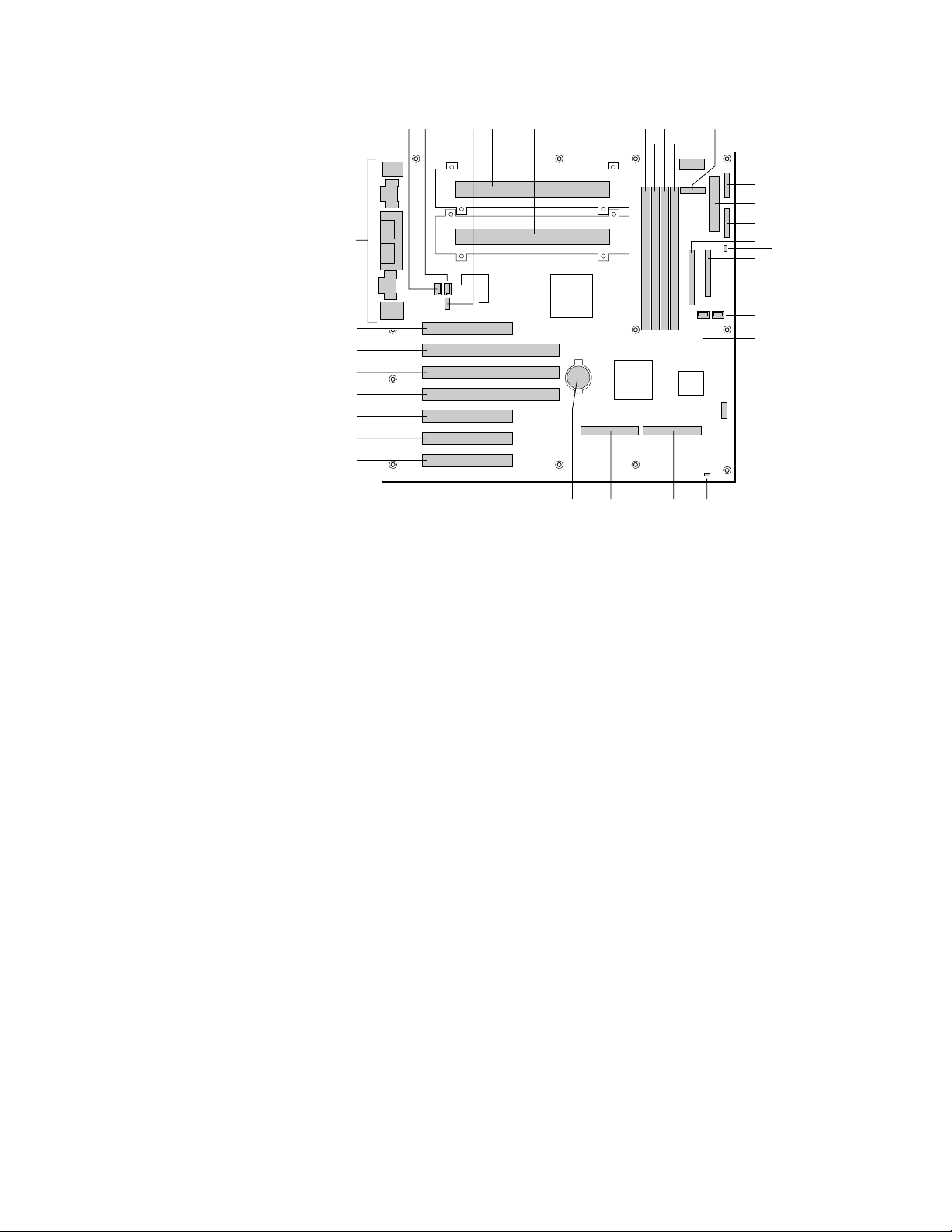
Server Board Components
DAB C E K
FF
F H
G I
J
L
M
N
O
P
Q
EE
DD
CC
BB
AA
Z
Y
A. Fan connector
B. Fan connector
C. CP U speed jumper block
D. Primary processor
E. Secondary processor
F. DIMM slot 4
G. DIMM slot 3
H. DI MM slot 2
I. DIMM slot 1
J. Power supply signal connector
K. Auxiliary power connector
L. Front panel connector P27
M. Power connector
N. Front panel connector P26
O. IDE connector
P. Speaker connector
Q. Floppy drive connector
R
S
T
VW
UX
OM10423
R. Fan connector
S. Fan connector
T. Configuration jumper block
U. Res e t switch connector
V. Single Ended (SE) SCSI
connector
W. LVD SCSI connector
X. Battery
Y. 33 MHz/32-bit PCI connector
Z. 33 MHz/32-bit PCI connector
AA. 33 MHz/32-bit PCI connector
BB. 33 MHz/64-bit PCI connector
CC. 66 MHz /64-bit PCI connector
DD. 66 MHz /64-bit PCI connector
EE. Half length 33 MHz/32-bit P CI
connector
FF. I/O ports
26 SBT2 Server Board Quick Start Guide
Page 27
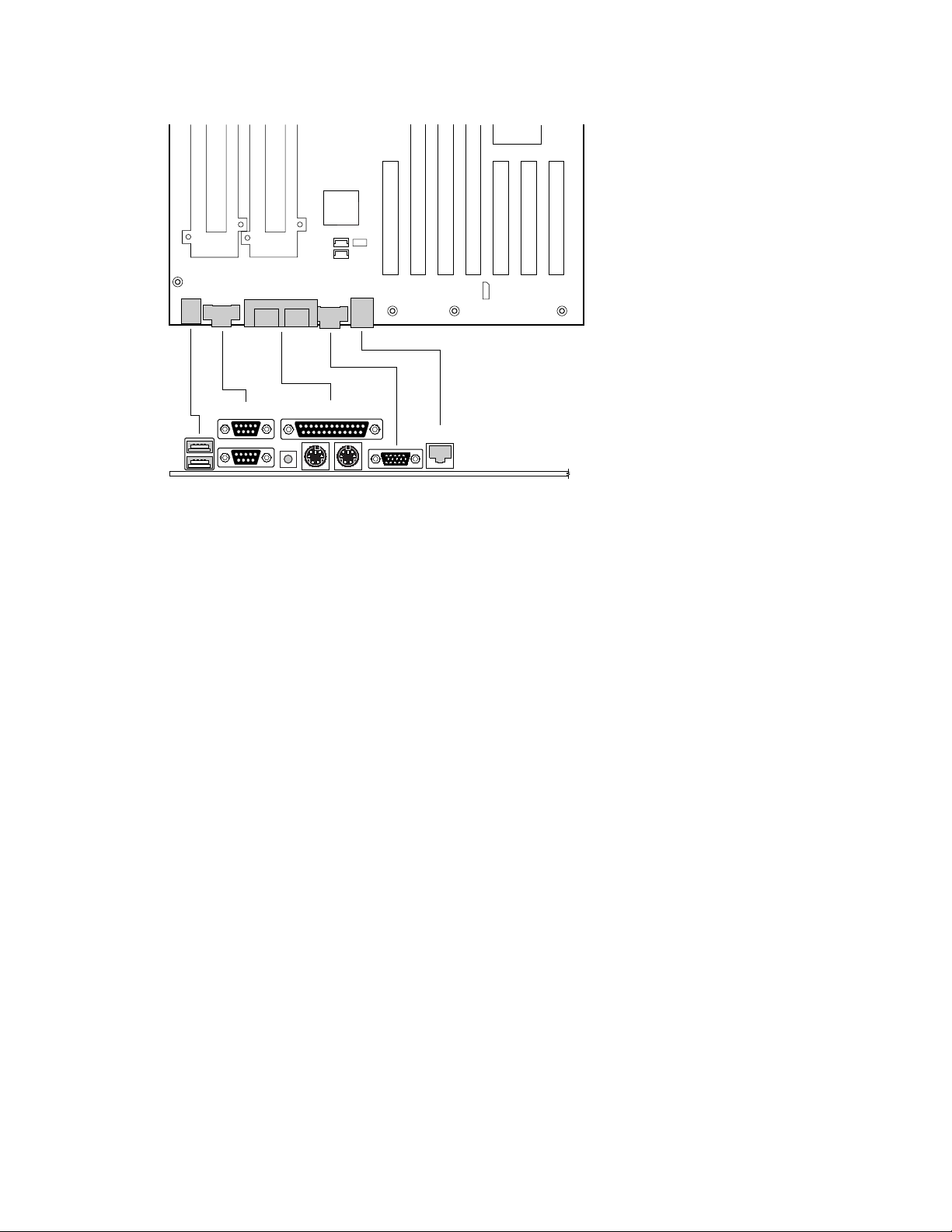
Back Panel Connectors
C
E
I
A
BD
A. USB connectors
B. Serial port 2 connector
C. S eri al port 1 connector
D. NM I switch
E. Keyboard connector
F. Mouse connector
G. Parallel port connect or
H. Video connector
I. Network connector
G
F
H
OM10424
SBT2 Server Board Quick Start Guide 27
Page 28

Getting Help
World Wide Web
http://support.intel.com/support/motherboards/server/sbt2
Telephone
Talk to a Customer Support Tec hni cian* (Intel reserves the right to change
pricing for telephone support at any time without notice).
am
In U.S.: 1-900-555-5800 (M–F, 7:00
Calls billed at U.S. $2.50 per minute.
In U.S. and Canada: 1-800-404-2284 (M–F, 7:00
Th 7:00
am
–3:00 pm, PST). Credit card cal l s billed at U.S. $25 per inci dent .
In Europe:
English language: +44-131-458-6847
French language: +44-131-458-6848
German language: +44-131-458-6954
Italian language: +44-131-458-6951
(M, Th, F, 8:00
Credit card calls billed at U.S. $25 per incident (levi ed i n l ocal currency at the
applicable credit card exc hange rate plus applicable VAT).
In Asia-Pacific region (Singapore local time, Oc t–April: M–F, 6:00
April–Oct: M–F, 5:00
Credit card calls billed at U.S. $25 per incident.
Australia (Sydney): +1-800-649-931
Hong Kong: +852-2-844-4456
Korea: +822-767-2595
PRC: +852-2-844-4456
Singapore: +65-831-1311
Taiwan: +886-2-718-9915
Rest of the world: Call the North American Service Center at +1-916-377-7000
(M–F, 7:00
Credit card calls billed at U.S. $25 per incident.
am
–5:00
pm,
T–W, 8:00
am
–4:00 pm).
am
–5:00 pm, U.S. pacific standard time).
–5:00 pm, Th 7:00 am–3:00 pm, PST).
am
–5:00 pm,
am
–4:00 pm, UK time)
am
–4:00 pm;
* Or contact your local dealer or distributor.
Technical Training & Support
If you are registered in the I nt el Product Dealer Program (North Americ a), the
Genuine Intel Dealer Program (Asia-P acific Region), or the Int el P roduct
Integrator Program (Europe/Latin America), you are eligible for technical training
and support.
In U.S. and Canada: 1-800-538-3373, ext. 442 (M –F, 5:00
In Europe: contact your di stributor or fax your detail s to European Literature
on +44 (0) 1793 513142.
In Asia: +65-831-1379 (M–F, 8:30 a
e-mail: APAC_gid@ccm.isin.intel.com
28 SBT2 Server Board Quick Start Guide
m
–5:30 pm, Singapore local time) or vi a
am
–5:00 pm, PST)
 Loading...