

Intel SBT2 - SS3LE DUAL SLOT2 UPTO 4GB EATX, SBT2 Product Manual

Intel® SBT2 Server Board
Product Guide
A Guide for Technically Qualified Assemblers of Intel® Identified Subassemblies/Products
Order Number: A28554-001

Disclaimer
Intel Corporation (Intel) makes no warranty of any kind with regard to this material, including, but not limited to,
the implied warranties of merchantability and fitness for a particular purpose. Intel assumes no responsibility
for any errors that may appear in this document. Intel makes no commitment to update nor to keep current the
information contained in this document. No part of this document may be copied or reproduced in any form or
by any means without prior written consent of Intel.
An Intel® product, when used in accordance with its associated documentation, is "Year 2000 Capable" when,
upon installation, it accurately stores, displays, processes, provides, and/or receives date data from, into, and
between the twentieth and twenty-first centuries, including leap year calculations, provided that all other
technology used in combination with said product properly exchanges date data with it.
†
Third party brands and trademarks are the property of their respective owners.
Copyright 2000 Intel Corporation.

Contents
1 Description
Server Board Features......................................................................................................... 7
Back Panel Connectors............................................................................................... 8
Server Board Connector and Component Locations.................................................... 9
Processor...................................................................................................................10
Memory ......................................................................................................................10
Add-in Board Slots..............................................................................................................11
Video...................................................................................................................................12
SCSI Controller...................................................................................................................12
IDE Controller......................................................................................................................12
Network Controller...............................................................................................................13
Network Teaming Features.........................................................................................13
Keyboard and Mouse..........................................................................................................15
ACPI ...................................................................................................................................15
Security...............................................................................................................................16
Security with Mechanical Locks and Monitoring..........................................................16
Software Locks...........................................................................................................16
2 Upgrading
Tools and Supplies Needed ................................................................................................19
Cautions..............................................................................................................................19
Memory...............................................................................................................................20
Processors..........................................................................................................................21
Adding or Replacing a Processor................................................................................22
Replacing the Back up Battery............................................................................................31
3 Configuration Software and Utilities
Hot Keys .............................................................................................................................33
Power-On Self Test (POST)................................................................................................34
Using BIOS Setup...............................................................................................................35
Record Your Setup Settings .......................................................................................35
If You Cannot Access Setup.......................................................................................35
Starting Setup .............................................................................................................35
Setup Menus ..............................................................................................................36
Main Menu..................................................................................................................36
Primary Master/Slave Submenu.................................................................................37
Advanced Menu..........................................................................................................37
Security Menu.............................................................................................................41
System Hardware Menu.............................................................................................42
Boot Menu..................................................................................................................42
Exit Menu ...................................................................................................................43
Using the System Setup Utility............................................................................................44
What You Need to Do.................................................................................................44
Running the SSU from the CD....................................................................................44
Running the SSU Remotely via an Emergency Management Card.............................45
iii

Starting the SSU.........................................................................................................45
Customizing th e SSU..................................................................................................47
Launching a Task.......................................................................................................47
SEL Manager Add-in..................................................................................................48
SDR Manager Add-in..................................................................................................48
FRU Manager Add-in..................................................................................................49
Exiting the SSU ..........................................................................................................50
FRUSDR Load Utility...........................................................................................................50
When to Run the FRUSDR Load Utility.......................................................................50
What You Need to Do.................................................................................................50
How You Use the FRUSDR Load Utility......................................................................51
Upgrading the BIOS............................................................................................................53
Preparing for the Upgrade ..........................................................................................53
Upgrading the BIOS....................................................................................................55
Recovering the BIOS..................................................................................................55
Changing the BIOS Language....................................................................................56
Using the Firmware Update Utility.......................................................................................56
Running the Firmware Update Utility...........................................................................56
Using the Adaptec SCSI Utility............................................................................................56
Running the SCSI Utility .............................................................................................57
4 Solving Problems
Resetting the System..........................................................................................................5 9
Initial System Startup ..........................................................................................................59
Checklist.....................................................................................................................59
Running New Application Software......................................................................................60
Checklist.....................................................................................................................60
After the System Has Been Running Correctly....................................................................60
Checklist.....................................................................................................................60
More Problem Solving Procedures......................................................................................61
Preparing the System for Diagnostic Testing..............................................................61
Monitoring POST........................................................................................................61
Verifying Proper Operation of Key System Lights.......................................................61
Confirming Loading of the Operating System..............................................................62
Specific Problems and Corrective Actions...........................................................................62
Power Light Does Not Light........................................................................................62
No Characters Appear on Screen...............................................................................62
Characters Are Distorted or Incorrect..........................................................................63
System Cooling Fans Do Not Rotate Properly............................................................63
Diskette Drive Activity Light Does Not Light................................................................64
Hard Disk Drive Activity Light Does Not Light .............................................................64
CD-ROM Drive Activity Light Does Not Light ..............................................................64
Cannot Connect to a Server .......................................................................................64
Problems with Network...............................................................................................65
PCI Installation Tips....................................................................................................65
Problems with Application Software.....................................................................................66
Bootable CD-ROM Is Not Detected.....................................................................................66
iv Contents

5 Technical Reference
Server Board Jumpers.........................................................................................................67
General Procedure to Change Jumper Setting...........................................................68
CMOS Jumper............................................................................................................68
Password Jumper.......................................................................................................69
6 Regulatory and Integration Information
Product Regulatory Compliance..........................................................................................71
Product Safety Compliance ........................................................................................71
Product EMC Compliance...........................................................................................71
Product Regulatory Compliance Markings..................................................................71
Electromagnetic Compatibility Notices.................................................................................72
USA............................................................................................................................72
FCC Verification Statement ........................................................................................73
ICES-003 (Canada)....................................................................................................73
Europe (CE Declaration of Conformity).......................................................................73
Japan EMC Compatibility............................................................................................73
BSMI (Taiwan)............................................................................................................74
Replacing the Back up Battery............................................................................................74
7 Equipment Log and Power Consumption Worksheets
Equipment Log....................................................................................................................75
Current Usage............................................................................................................77
Calculating Power Consumption.................................................................................77
Index.......................................................................................................................................81
Figures
1. Back Panel Connectors............................................................................................... 8
2. Server Board Connector and Component Locations.................................................... 9
3. Installing DIMMs.........................................................................................................20
4. Remove the Top Epac ................................................................................................22
5. Remove Auxiliary Fans...............................................................................................23
6. Remove Bottom Epac.................................................................................................24
7. Disengage Retention Wires........................................................................................25
8. Installing a Processor .................................................................................................26
9. Engage Retention Wires.............................................................................................27
10. Install Bottom Epac.....................................................................................................28
11. Install Fans.................................................................................................................29
12. Install Top Epac..........................................................................................................30
13. System Setup Utility Main Window.............................................................................46
14. Jumper Locations.......................................................................................................67
SBT2 Server Board Product Guide v

Tables
1. Server Board Features ................................................................................................ 7
2. Software Security Features ........................................................................................17
3. Configuration Utilities..................................................................................................33
4. Hot Keys.....................................................................................................................33
5. CPU Clock Speed (7C10) Jumper..............................................................................67
6. Configura tion Jumper (3N 7 )........................................................................................6 7
7. Power Usage Worksheet 1.........................................................................................78
8. Power Usage Worksheet 2.........................................................................................79
vi Contents

1 Description
Server Board Features
Table 1. Server Board Features
Feature Description
Processor Installed: Up to two Intel® Pentium® III Xeon TM processors. You must use an
Memory (DRAM) Four 72 bit sockets for 168-pin, gold contact, 133 MHz, 3.3V, PC/133 compliant,
Video Memory Installed: 4 MB of video memory.
PCI bus Four standard PCI (PCI-33/32 bit) expansion slots for add-in boards.
Graphics Integrated onboard ATI Rage IIC 64 bit SVGA controller.
SCSI Adaptec† AIC- AIC7899, supporting onboard Ultra2 (LVD) wide and Ultra-wide
Network Integrated onboard NIC, an Intel® 82559 single chip PCI LAN controller for 10 or
System I/O PS/2†-compatible keyboard and mouse ports, 6 pin DIN.
Form Factor Server ATX form factor, ATX 2.01 compliant I/O.
®
boxed processor with one of the following product codes:
Intel
BX80526KB866256, BX80526KB001256
registered, SDRAM dual inline memory modules (DIMM).
Two PCI-66 MHz/64 bit expansion slots.
One PCI-33 MHz/64 bit expansion slots
SCSI interfaces.
100 Mbps TX Fast Ethernet networks. RJ-45 Ethernet connector at I/O back
panel.
Advanced parallel port, supporting Enhanced Parallel Port (EPP) level 1.7
and 1.9, ECP, compatible 25 pin.
VGA video port, 15 pin.
Two serial ports, 9 pin.
RJ-45 Ethernet port.
Two USB ports.
7
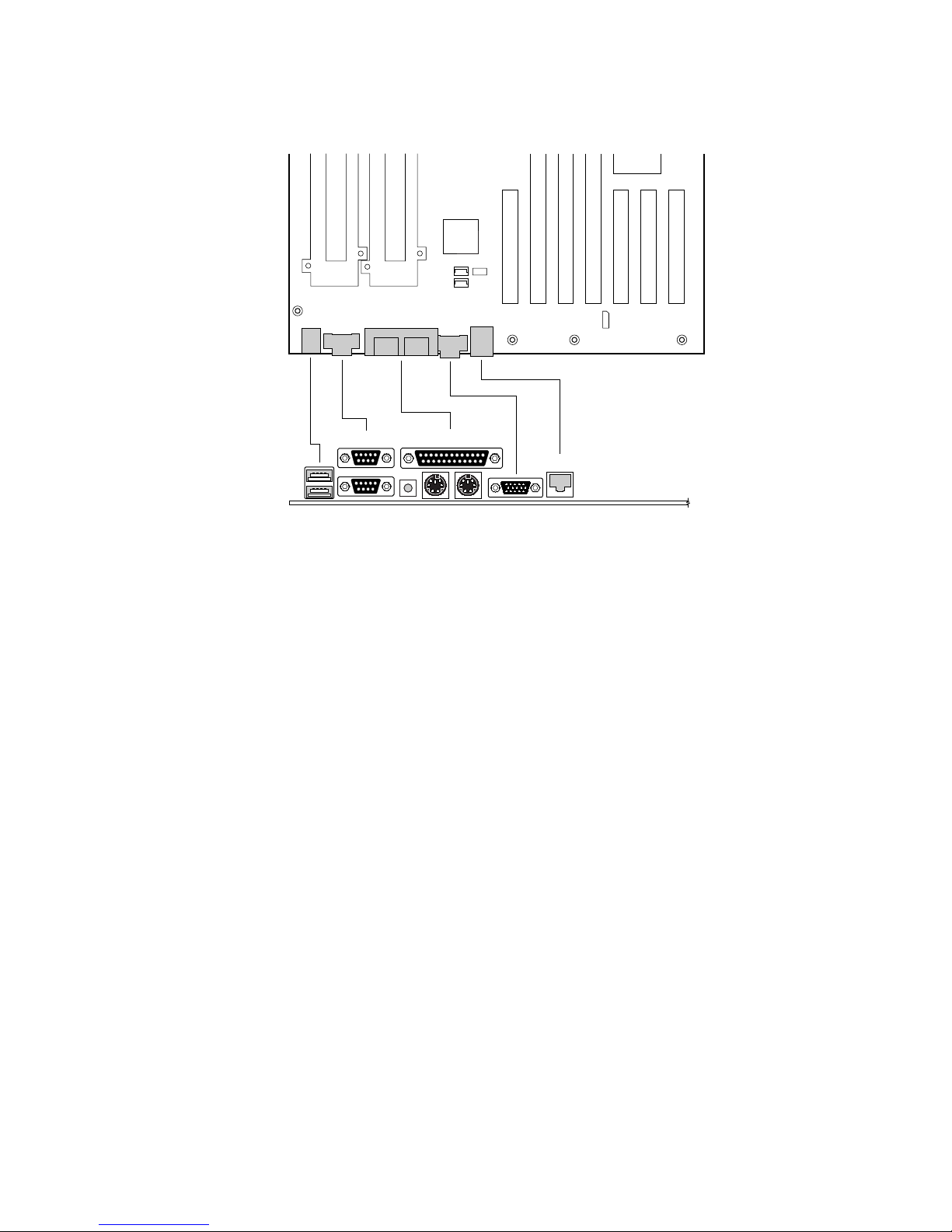
Back Panel Connectors
A
C
BD
A. USB connectors
B. Serial port 2 connector
C. Serial port 1 connector
D. NMI switch
E. Keyboard connector
F. Mouse connector
G. Parallel port connector
H. Video connector
I. Network connector
E
F
G
I
H
Figure 1. Back Panel Connectors
OM10424
8 Description
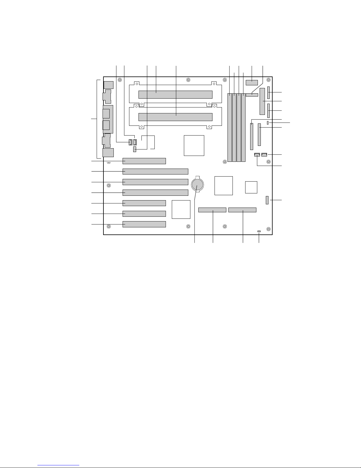
Server Board Conne ctor and Component Locations
FF
EE
DD
CC
BB
AA
DA B C E K
F H
J
G I
L
M
N
O
P
Q
R
S
T
Z
Y
VW
A. Fan connector
B. Fan connector
C. CPU speed jumper block
D. Primary processor
E. Secondary processor
F. DIMM slot 4
G. DIMM slot 3
H. DIMM slot 2
I. DIMM slot 1
J. Power supply signal connector
K. Auxiliary power connector
L. Front panel connector P27
M. Power connector
N. Front panel connector P26
O. IDE connector
P. Speaker connector
Q. Floppy drive connector
R. Fan connector
S. Fan connector
T. Configuration jumper block
U. Reset switch connector
V. SE SCSI connector
W. LVD SCSI connector
X. Battery
Y. 33 MHz/32-bit PCI connector
Z. 33 MHz/32-bit PCI connector
AA. 33 MHz/32-bit PCI connector
BB. 33 MHz/64-bit PCI connector
CC. 66 MHz/64-bit PCI connector
DD. 66 MHz/64-bit PCI connector
EE. 33 MHz/32-bit PCI connector
FF. I/O ports
Figure 2. Server Board Connector and Component Locations
UX
OM10423
SBT2 Server Board Product Guide 9

Processor
NOTE
✏
The SBT2 server board only supports processors with the following product
codes: BX80526KB866256, BX80526KB1000256, BX80526KB8001M.
Future processors may be supported. See the SBT2 support website for more
information.
Each Pentium III Xeon processor is packaged in a cartridge containing the processor core with an
integrated 16 KB primary (L1) cache, a secondary (L2) cache, and a cover. A passive heat sink is
attached to the back cover of the cartridge. The cartridge is secured to the system board by a
retention module and electrically connected to the board through a Slot 2 connector.
The processor external interface operates at a maximum of 133 MHz. The second-level cache is on
the substrate of the processor cartridge.
Memory
The system board contains four 168-pin DIMM sockets. Memory is partitioned as four banks of
registered SDRAM DIMMs (PC133 compatible), each providing 72 bits of noninterleaved memory
(64-bit main memory plus ECC).
Memory should be added in order from slot 1 to slot 4.
The controller automatically detects, sizes, and initializes the memory array, depending on the type,
size, and speed of the installed DIMMs, and reports memory size and allocation to the server via
configuration registers.
NOTE
✏
Use DIMMs that have been tested for compatibility with the server board.
Contact your sales representative or dealer for a current list of approved
memory modules. Check the Intel Customer Support website for the latest
tested memory list:
http://support.intel.com/support/motherboards/server/SBT2/compat.htm
10 Description

Add-in Board Slots
The server board has three full length and one half length standard PCI (PCI-33/32 bit) connectors.
PCI features:
• Bus speed up to 33 MHz
• 32 bit memory addressing
• 5 V signaling environment
• Burst transfers of up to 133 Mbps
• 8, 16, or 32 bit data transfers
• Plug and Play ready
• Parity enabled
The server board has two full length PCI-66/64 bit. PCI features:
• Bus speed up to 66 MHz
• 32 bit memory addressing
• 5 V/3.3 V signaling environment
• Burst transfers of up to 528 Mbps
• 8, 16, 32, or 64 bit data transfers
• Plug and Play ready
• Parity enabled
The server board has one full length PCI-33/64 bit. PCI features:
• Bus speed up to 33 MHz
• 32 bit memory addressing
• 5 V/3.3 V signaling environment
• Burst transfers of up to 264 Mbps
• 8, 16, 32, or 64 bit data transfers
• Plug and Play ready
• Parity enabled
NOTE
✏
If you install a PCI-33 card into one of the PCI-66 slots, the bus speed for all
three slots will be lowered to 33 MHz.
SBT2 Server Board Product Guide 11

Video
The system has an integrated ATI Rage IIC 64 bit high-performance SVGA subsystem that
supports the following:
• BIOS compatibility with VGA, EGA, CGA, Hercules Graphics, and MDA
• 4 MB of 10 ns onboard Synchronous Graphics Memory (SGRAM)
• Pixel resolutions up to 1280 X 1024
• Analog VGA monitors (single and multiple frequency, interlaced and noninterlaced) with a
maximum vertical retrace noninterlaced frequency of 100 Hz.
SCSI Controller
The embedded Adaptec AIC-7899 dual function SCSI controller provides both Ultra2 (LVDS)
wide and Ultra wide (SE) SCSI interfaces as two independent PCI functions.
The SCSI bus is terminated on the server board with active terminators that cannot be disabled.
The onboard device must always be at one end of the bus. The device at the end of the cable must
be terminated. LVDS devices generally do not have termination capabilities. Non-LVDS devices
generally are terminated through a jumpe r or resis tor pack.
IDE Controller
The system includes a single channel enhanced IDE 32 bit interface controller for intelligent disk
drives with disk controller electronics onboard. The controller has a connector located on the
system board that supports a master and a slave device.
The device controls:
• PIO and DMA transfer modes
• DMA-33 capable
• Mode 4 timings
• Transfer rates up to 33 MB/s
• Buffering for PCI/IDE burst transfers
• Master/slave IDE mode
• Up to two devices.
12 Description

Network Controller
NOTE
✏
To ensure EMC product regulation compliance, the end system must be used
with a shielded LAN cable.
The server board includes a 10BASE-T/100BASE-TX network solution based on the Intel 82559
single chip Fast Ethernet PCI Bus Controller. As a PCI bus master, the controller can burst data at
up to 132 MB/s. The controller contains two receive and transmit FIFO buffers that prevent data
overruns or underruns while waiting for access to the PCI bus. The controller has the following:
• 32 bit PCI bus master interface (direct drive of bus), compatible with PCI Bus Specification,
Revision 2.1
• Chained memory structure with improved dynamic transmit chaining for enhanced
performance
• Programmable transmit threshold for improved bus utilization
• Early receive interrupt for concurrent processing of receive data
• Onchip counters for network management
• Autodetect and autoswitching for 10 or 100 Mbps network speeds
• Support for both 10 Mbps and 100 Mbps networks, capable of full or half duplex, with back-to-
back transmit at 100 Mbps
Network Teaming Features
The network controller provides several options for increasing throughput and fault tolerance when
†
running Windows NT
• Adapter Fault Tolerance (AFT) - provides automatic redundancy for your adapter. If the
primary adapter fails, the secondary takes over. AFT works with any hub or switch.
• Adaptive Load Balancing (ALB) - creates a team of 2 - 4 adapters to increase transmission
throughput. Also includes AFT. Works with any 10Base-TX or 100Base-TX switch.
• Fast EtherChannel
reception throughput. Also includes AFT. Requires an FEC-enabled switch.
To set up an option, read the instructions in the Windows NT 4.0 or NetWare 4.1x readme files.
4.0, Windows† 2000 or NetWare† 4.1x or newer:
†
(FEC) - creates a team of 2, 3 or 4 adapters to increase transmission and
SBT2 Server Board Product Guide 13

General Configuration Notes
1. Windows NT versions prior to 4.0 don’t support Adapter Teaming options.
2. Adapter Teaming options require NT 4.0 with Service Pack 4.0 or Service Pack 3.0 and Hotfix.
3. In Windows NT, teaming options cannot be implemented on adapters that have been
configured for VLANs. NetWare can support teaming options and VLANs on the same
adapters.
Adapter Fault Tolerance
Adapter Fault Tolerance (AFT) is a simple, effective, and fail-safe approach to increase the
reliability of server connections. AFT gives you the ability to set up link recovery to the server
adapter in case of a cable, port, or network interface card failure. By assigning two PRO/100
Intelligent Server adapters as a team, AFT enables you to maintain uninterrupted network
performance.
AFT is implemented with two PRO/100 Intelligent Server adapters: a primary adapter and a
backup, or secondary, adapter. During normal operation, the backup will have transmit disabled. If
the link to the primary adapter fails, the link to the backup adapte r auto mat ica lly takes ove r.
Preferred Primary Adapter
With multiple adapters installed, you can specify one as the Preferred Primary adapter. For
example if you have a server with a PRO/100 Intelligent Server adapter as the primary adapter and
a PRO/100+ adapter as the secondary, you would want the PRO/100 Intelligent Server adapter to be
the preferred primary. In this scenario, if the PRO/100 Intelligent Server adapter fails, the
PRO/100+ will take over. Then when the PRO/100 Intelligent Server adapter is replaced, it will
automatically revert to being the primary adapter in the team.
If a Preferred Primary is not selected, PROSet will attempt to select the best adapter, based on
adapter model and speed.
Mixed Adapter Teaming
AFT supports up to four PRO/1000 or PRO/100 adapters per team, in any mix.
Adaptive Load Balancing
Adaptive Load Balancing (ALB) is a simple and efficient way to increase your server’s transmit
throughput. With ALB you group PRO/100 Intelligent Server adapters in teams to provide an
increased transmit rate (up to 400 Mbps) using a maximum of four adapters. The ALB software
continuously analyzes transmit loading on each adapter and balances the rate across the adapters as
needed. Adapter teams configured for ALB also provide the benefits of AFT. Receive rates remain
at 100 Mbps.
To use ALB, you must have two, three, or four PRO/100 Intelligent Server adapters installed in
your server or workstation and linked to the same network switch.
14 Description

Cisco Fast EtherChannel
Fast EtherChannel (FEC) is a performance technology developed by Cisco to increase your server’s
throughput. Unlike ALB, FEC can be configured to increase both transmission and reception
channels between your server and switch. FEC works only with FEC-enabled switches, such as the
Catalyst 5000 series. With FEC, as you add adapters to your server, you can group them in teams
to provide up to 800 Mpbs at full duplex, with a maximum of four PRO/100 Intelligent Server
adapters. The FEC software continuously analyzes loading on each adapter and balances network
traffic across the adapters as needed. Adapter teams configured for FEC also provide the benefits
of AFT.
To use FEC, you must have two or four PRO/100 Intelligent Server adapters installed in your
server and linked to the same FEC-enabled Cisco switch.
Keyboard and Mouse
The keyboard/mouse controller is PS/2-compatible. The server may be locked automatically if
there is no keyboard or mouse activity for a predefined length of time, if specified through the
System Setup Utility (SSU). Once the inactivity (lockout) timer has expired, the keyboard and
mouse do not respond until the previously stored password is entered.
ACPI
The SBT2 supports the Advanced Configuration and Power Interface (ACPI) as defined by the
ACPI 1.0 and PC97 specifications. An ACPI aware operating system can put the system into a
state where the hard drives spin down, the system fans stop, and all processing is halted. However,
the power supply will still be on and the processors will still be dissipating some power, so the
power supply fan and processor fans will still run.
The SBT2 supports sleep states s0, s1, s4, and s5. With future versions of Microsoft Windows 9X
that support ACPI, the BIOS will only support sleep states s0, s1, and s5. With future versions of
Microsoft Windows NTx that support ACPI, the BIOS will support sleep states s0, s1, s4, and s5.
• s0: Normal running state.
• s1: Processor sleep state. No context will be lost in this state and the processor caches will
maintain coherency.
• s4: Hibernate or Save to Disk: The memory and machine state are saved to disk. Pressing the
power button or other wakeup event will restore the system state from the disk and resume
normal operation. This assumes that no hardware changes have been made to the system while
it was off.
• s5: Soft off: Only the RTC section of the PIIX4 and the BMC are running in this state.
CAUTION
The system is off only when the AC power is disconnected.
SBT2 Server Board Product Guide 15

Security
To help prevent unauthorized entry or use of the server, Intel® Server Control server management
software monitors the system intrusion switch.
Security with Mechanical Locks and Monitoring
If installed, you can activate the chassis intrusion alarm switch. When the side door is opened, the
switch transmits an alarm signal to the server board, where BMC firmware and server management
software process the signal. The system can be programmed to respond to an intrusion by
powering down or by locking the keyboard, for example.
Software Locks
The BIOS Setup and the System Setup Utility (SSU) provide a number of security features to
prevent unauthorized or accidental access to the system. Once the security measures are enabled,
you can access the system only after you enter the correct password(s). For example:
• Enable the keyboard lockout timer so that the server requires a password to reactivate the
keyboard and mouse after a specified time out period1 to 120 minutes.
• Set and enable an supervisor password.
• Set and enable a user password.
• Set secure mode to prevent keyboard or mouse input and to prevent use of the front panel reset
and power switches.
• Activate a hot key combination to enter secure mode quickly.
• Disable writing to the diskette drive when secure mode is set.
• Disable access to the boot sector of the operating system hard disk drive.
Using Passwords
You can set either the user password, the supervisor password, or both passwords. If only the user
password is set, you:
• Must enter the user password to enter BIOS Setup or the SSU.
• Must enter the user password to boot the server if Password on Boot is enabled in either the
BIOS Setup or SSU.
• Must enter the user password to exit secure mode.
If only the supervisor password is set, you:
• Must enter the supervisor password to enter BIOS Setup or the SSU.
• Must enter the supervisor password to boot the server if Password on Boot is enabled in either
the BIOS Setup or SSU.
• Must enter the supervisor password to exit secure mode.
If both passwords are set, you:
• May enter the user password to enter BIOS Setup or the SSU. However, you will not be able to
change many of the options.
• Must enter the supervisor password if you want to enter BIOS Setup or the SSU and have
access to all of the options.
16 Description

• May enter either password to boot the server if Password on Boot is enabled in either the BIOS
Setup or SSU.
• May enter either password to exit secure mode.
Secure Mode
Configure and enable the secure boot mode by using the SSU. When secure mode is in effect:
• You can boot the server and the operating system will run, but you must enter the user
password to use the keyboard or mouse.
• You cannot turn off system power or reset the server from the front panel switches.
Secure mode has no effect on functions enabled via the Server Manager Module or power control
via the real time clock.
Taking the server out of secure mode does not change the state of system power. That is, if you
press and release the power switch while secure mode is in effect, the system will not be powered
off when secure mode is later removed. However, if the front panel power switch remains
depressed when secure mode is removed, the server will be powered off.
Summary of Software Security Features
The table below lists the software security features and describes what protection each offers. In
general, to enable or set the features listed here, you must run the SSU and go to the Security
Subsystem Group, menu. The table also refers to other SSU menus and to the Setup utility.
Table 2. Software Security Features
Feature Description
Secure mode How to enter secure mode:
• Setting and enabling passwords automatically places the system in secure
mode.
• If you set a hot-key combination (through Setup), you can secure the
system simply by pressing the key combination. This means you do not
have to wait for the inactivity time-out period.
When the system is in secure mode:
The server can boot and run the opera ting system, but mouse and keyboard
input is not accepted until the user password is entered.
At boot time, if a CD is detected in the CD-ROM drive or a diskette in drive A,
the system prompts for a password. When the password is entered, the
server boots from CD or diskette and disables the secure mode.
If there is no CD in the CD-ROM drive or diskette in drive A, the server boots
from drive C and automatically goes into secure mode. All enabled secure
mode features go into effect at boot time.
To leave secure mode: Enter the correct password(s).
Disable writing to diskette In secure mode, the server will not boot from or write to a diskette unless a
password is entered.
To write protect access to diskette whether the server is in secure mode or
not, use the Setup main menu, Floppy Options, and specify Floppy Access as
read only.
continued
SBT2 Server Board Product Guide 17

Table 2. Software Security Features (continued)
Feature Description
Set a time out period so
that keyboard and mouse
input are not accepted
Also, screen can be
blanked, and writes to
diskette can be inhibited
Specify and enable an inactivity time out period of from 1 to 120 minutes.
If no keyboard or mouse action occurs for the specified period, attempted
keyboard and mouse input will not be accepted.
The monitor display will go blank, and the diskette drive will be write protected
(if these security features are enabled through Setup).
To resume activity: Enter the correct password(s).
Control access to using
the SSU: set supervisor
password
To control access to setting or changing the system configuration, set an
supervisor password and enable it through Setup.
If both the supervisor and user passwords are enabled, either can be used to
boot the server or enable the keyboard and/or mouse, but only the supervisor
password will allow Setup to be changed.
To disable a password, change it to a blank entry or press CTRL-D in the
Change Password menu of the Supervisor Password Option menu found in
the Security Subsystem Group.
To clear the password if you cannot access Setup, change the Clear
Password jumper (see Chapter 5).
Control access to the
system other than SSU:
set user password
To control access to using the system, se t a user password and enable it
through Setup.
To disable a password, change it to a blank entry or press CTRL-D in the
Change Password menu of the User Password Option menu found in the
Security Su bsystem Group.
To clear the password if you cannot access Setup, change the Clear
Password jumper (see Chapter 5).
Boot without keyboard The system can boot with or without a keyboard. During POST, before the
system completes the boot sequence, the BIOS automatically detects and
tests the keyboard if it is present and displays a message.
Specify the boot sequence The sequence that you specify in setup will determine the boot order. If
secure mode is enabled (a user password is set), then you will be prompted
for a password before the server fully boots. If secure mode is enabled and
the “Secure Boot Mode” option is also enabled, the server will fully boot but
will require a password before accepting any keyboard or mouse input.
18 Description

2 Upgrading
Tools and Supplies Needed
• Phillips (cross head) screwdriver (#1 bit and #2 bit)
• Jumper removal tool or needle nosed pliers
• Pen or pencil
• Antistatic wrist strap and conductive foam pad (recommended)
Cautions
These warnings and cautions apply throughout this chapter. Only a technically qualified person
should configure the server board.
CAUTIONS
System power on/off: The power button DOES NOT turn off the system
AC power. To remove power from system, you must unplug the AC power
cord from the wall outlet. Make sure the AC power cord is unplugged before
you open the chassis, add, or remove any components.
Hazardous conditions, devices & cables: Hazardous electrical
conditions may be present on power, telephone, and communication cables.
Turn off the server and disconnect the power cord, telecommunications
systems, networks, and modems attached to the server before opening it.
Otherwise, personal injury or equipment damage can result.
Electrostatic discharge (ESD) & ESD protection: ESD can damage
disk drives, boards, and other parts. We recommend that you perform all
procedures in this chapter only at an ESD workstation. If one is not
available, provide some ESD protection by wearing an antistatic wrist strap
attached to chassis groundany unpainted metal surfaceon your server
when handling parts.
ESD and handling boards: Always handle boards carefully. They can
be extremely sensitive to ESD. Hold boards only by their edges. After
removing a board from its protective wrapper or from the server, place the
board component side up on a grounded, static free surface. Use a
conductive foam pad if available but not the board wrapper. Do not slide
board over any surface.
Installing or removing jumpers: A jumper is a small plastic encased
conductor that slips over two jumper pins. Some jumpers have a small tab on
top that you can grip with your fingertips or with a pair of fine needle nosed
pliers. If your jumpers do not have such a tab, take care when using needle
nosed pliers to remove or install a jumper; grip the narrow sides of the
19
jumper with the pliers, never the wide sides. Gripping the wide sides can
damage the contacts inside the jumper, causing intermittent problems with
the function controlled by that jumper. Take care to grip with, but not
squeeze, the pliers or other tool you use to remove a jumper, or you may
bend or break the stake pins on the board.
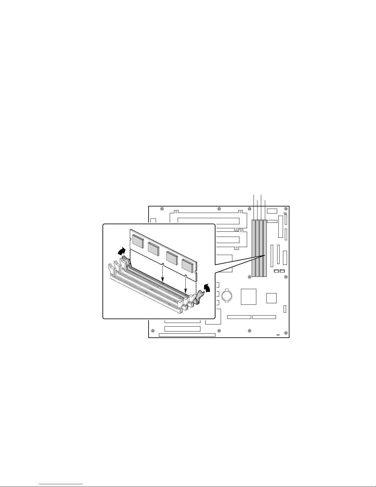
Memory
Only PC133-compliant SDRAM is supported by the server board. Install from 64 MB to 4 GB of
registered memory, using up to four single- or double-banked DIMMs.
DIMMs must be installed in order from slot 1 to slot 4, no empty slots between installed DIMMs.
Slot 1 is the slot farthest from the processors.
Installed DIMMs must be the same speed and must all be registered. For a list of supported
memory, call your service representative or visit the Intel Support website:
http://support.intel.com/support/motherboards/server/SBT2/compat.htm
214
3
20 Upgrading
OM10426
Figure 3. Installing DIMMs

Processors
WARNING
If the server has been running, any installed processor and heat sink on
the processor board(s) will be hot. To avoid the possibility of a burn, be
careful when removing or installing server board components that are
located near processors.
CAUTIONS
Processor must be appropriate: You may damage the server if you
install a processor that is inappropriate for your server. Make sure your
server can handle a newer, faster processor (thermal and power
considerations). For exact information about processor interchangeability,
contact your customer service representative or visit the Intel Customer
Support website:
http://support.intel.com/support/motherboards/server/SBT2
Heat sink must be appropriate: You must use an Intel boxed processor
with one of the following product codes: BX80526KB866256,
BX80526KB1000256, BX80526KB8001M
ESD and handling processors: Reduce the risk of electrostatic
discharge (ESD) damage to the processor by doing the following: (1) Touch
the metal chassis before touching the processor or server board. Keep part of
your body in contact with the metal chassis to dissipate the static charge
while handling the processor. (2) Avoid moving around unnecessarily.
SBT2 Server Board Product Guide 21
Adding or Replacing a Processor
If you are adding a second processor to your system, you must first remove the termination card
from the secondary processor slot. The second processor must be compatible with the first
processor (within one stepping, sa me voltage, see the Int el suppo rt w ebs ite fo r speci fics).
1. Observe the safety and ESD precautions at the beginning of this chapter and the additional
cautions given here.
2. Remove the side cover (see your system or chassis documentation for instructions).
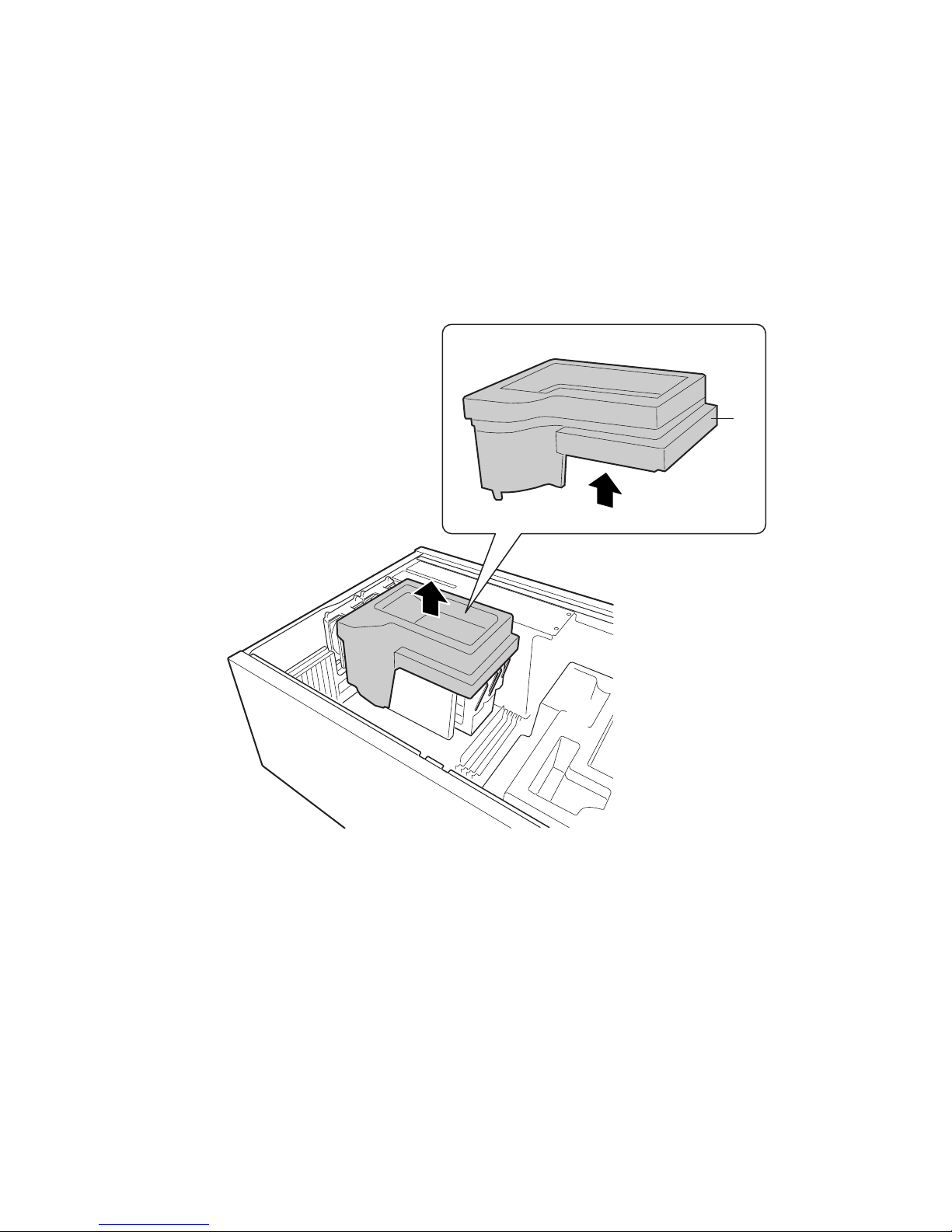
3. Remove the top piece of epac covering the processors
A
22 Upgrading
OM10615
A. Epac
Figure 4. Remove the Top Epac
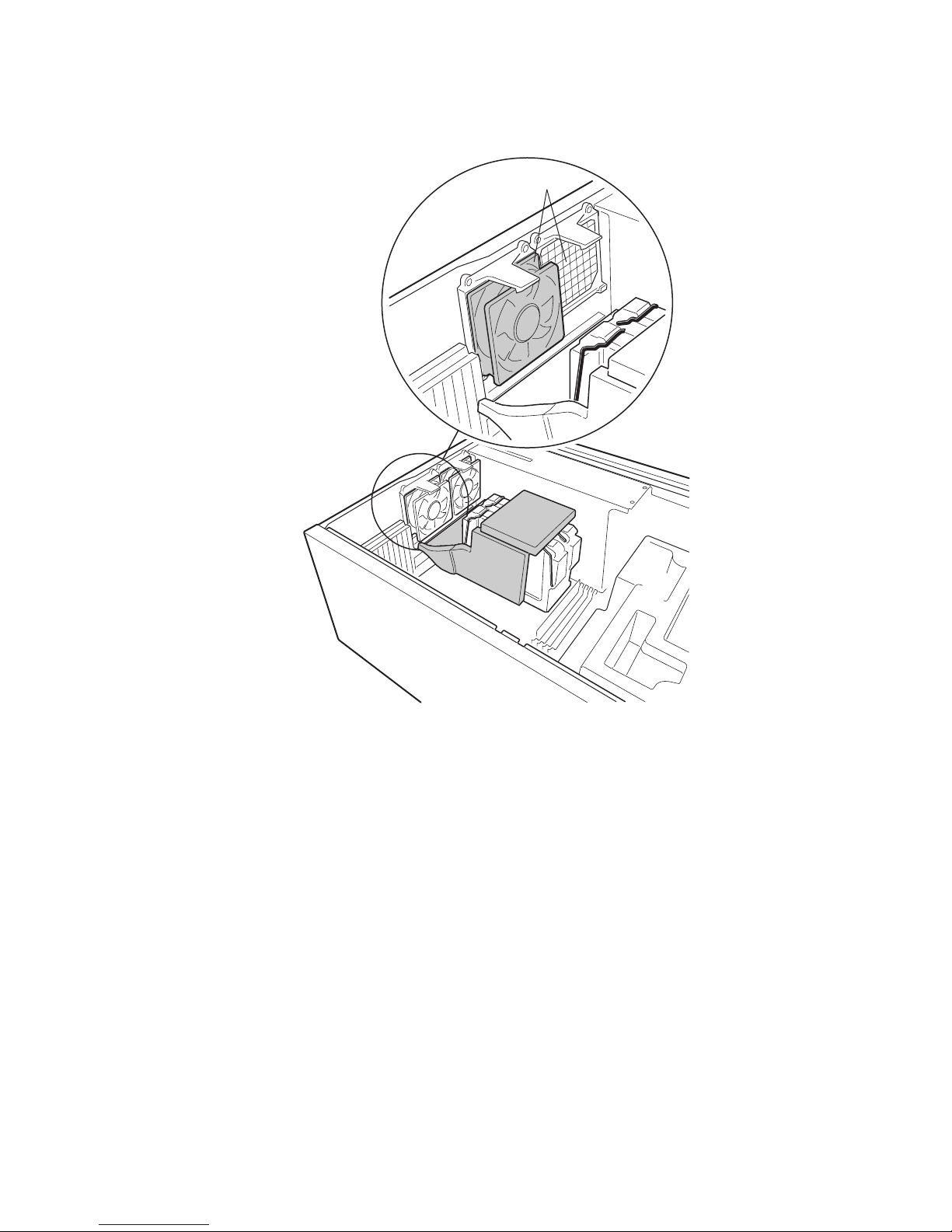
4. Remove the auxiliary cooling fans from their brackets. Do not disconnect them from the board.
A
A. Fans
Figure 5. Remove Auxiliary Fans
OM10419
SBT2 Server Board Product Guide 23
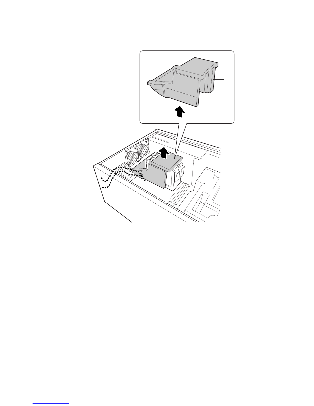
5. Remove the bottom piece of foam epac. It lifts straight out; do not tilt it.
A
A. Epac
Figure 6. Remove Bottom Epac
OM10616
24 Upgrading
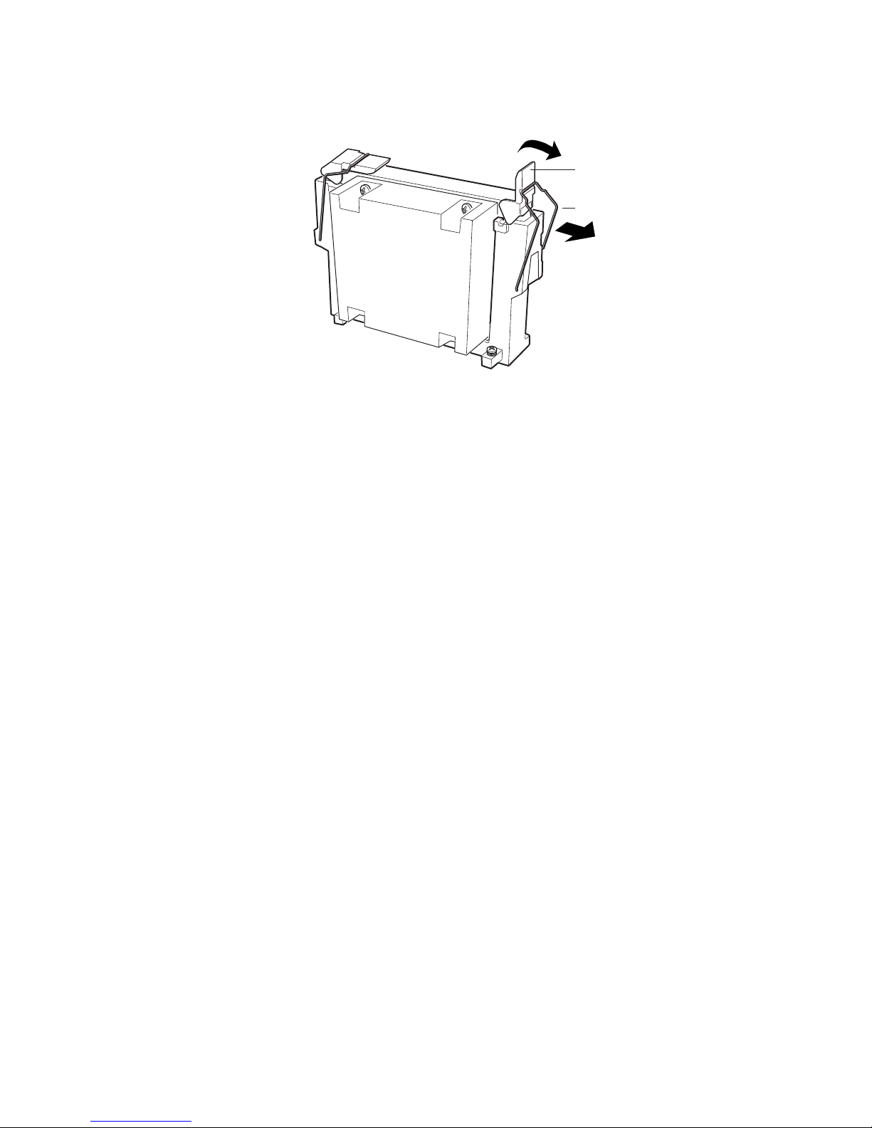
6. Lift the plastic ejectors on the processor or termination card to disengage the retention wires.
A
B
OM10617
A. Retention wires
B. Ejectors
Figure 7. Disengage Retention Wires
7. Pull the processor or termination card from the system.
SBT2 Server Board Product Guide 25
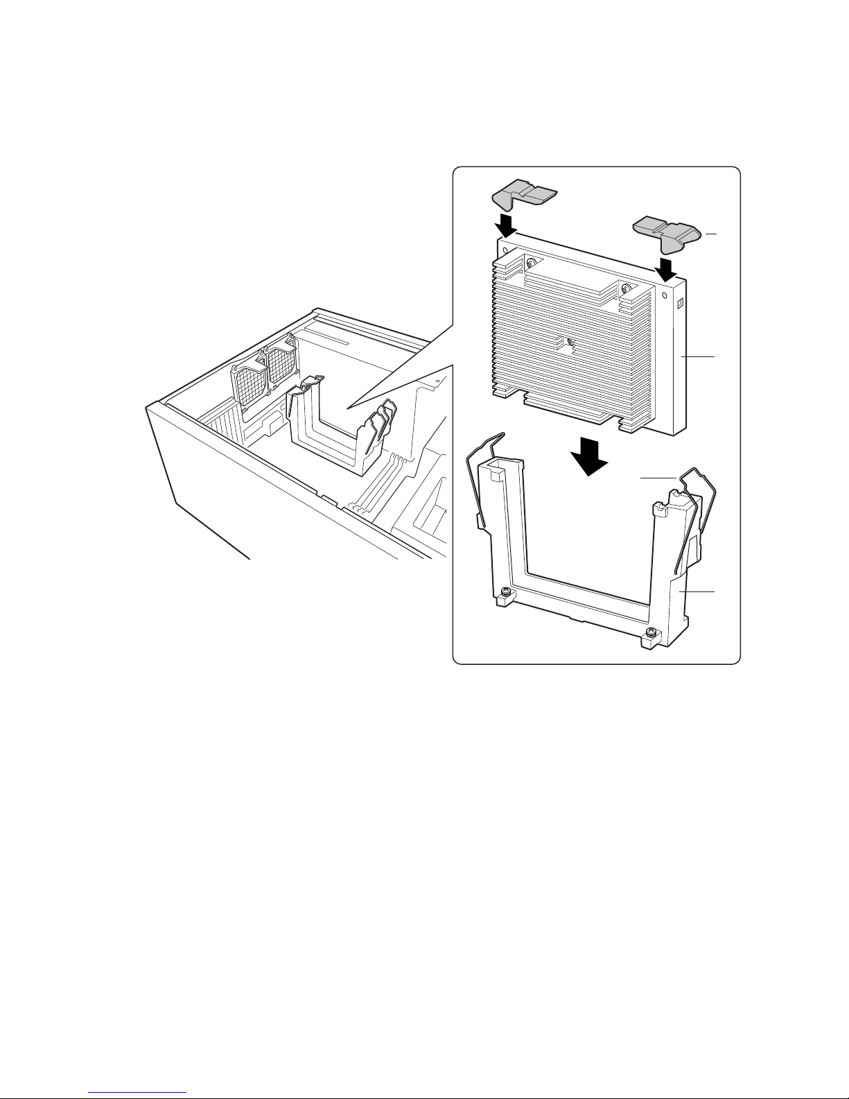
8. Clip two plastic ejectors (Figure 8, A) to the new processor (Figure 8, B).
9. Slide the new processor into the processor slot. Push down firmly, with even pressure on both
sides of the top, until the processor is seated in the processor connector on the server board.
A
B
C
A. Ejectors
B. Processor
C. Retention wires
D. Retention Mechanism
Figure 8. Installing a Processor
D
OM10413
26 Upgrading
 Loading...