

Page 1
SBC-370
SOCKET 370 CELERON, PENTIUM III
Board Processor Guide
Page 2

Brand or product names are trademarks or registered trademarks of their respective owners.
Windows and Windows NT are registered trademarks of Microsoft Corp. in the United States and other countries.
This document is copyrighted by Xycom Automation, Incorporated (Xycom Automation) and shall not be reproduced or
copied without expressed written authorization from Xycom Automation.
The information contained within this document is subject to change without notice. Xycom Automation does not guaran
tee the accuracy of the information.
Precautions
Some components on SBC-370 are very sensitive to static electric charges and can be damaged by a sudden rush of power.
To protect it from unintended damage, be sure to follow these precautions:
Ground yourself to remove any static charge before touching the SBC-370. You can do this by using a grounded wrist strap
at all times or by frequently touching any conducting materials that are connected to the ground.
Handle your SBC-370 by its edges. Don't touch IC chips, leads, or circuitry if not necessary.
Do not plug any connector or jumper while the power is on.
Do not put your SBC-370 unprotected on a flat surface because it has components on both sides.
BATTERY REPLACEMENT CAUTION
Danger of explosion if battery is incorrectly replaced. Replace only with the same or equivalent type recommended by the
manufacturer. Dispose of used batteries according to the manufacturer's instructions.
-
2
Page 3

Table of Contents
1. Features. . ..............................6
OVERVIEW .................................................6
Feature LIST .................................................6
CPU...................................................6
SDRAM .................................................6
AGP VGA Controller...........................................7
Ethernet Controller ...........................................7
Ultra DMA/33 Enhanced PCI EDI Interface ...............................7
Multi-I/O Chip .............................................7
Floppy Disk Drive Interface .......................................7
Two High Speed Series Ports.......................................7
Parallel Port ...............................................7
Hardware Monitoring System ......................................8
IrDAPort................................................8
USBPort.................................................8
ISAPLUS.................................................8
E2Key™.................................................8
Watchdog Timer.............................................8
Flash Disk - DiskOnChip™........................................8
ATX Power Supply Function .......................................8
Power Consumption...........................................8
Operating Humidity ...........................................9
Watchdog Timer...............................................9
2
KEY™ FUNCTION .............................................9
E
Connecting to an ATX Power Supply ....................................10
2. Board Configuration .........................12
Board Layout ................................................12
Jumpers ..................................................13
CPU Frequency Setting (JP3) ......................................13
CPU Multiplier Setting (JP8) ......................................13
Watchdog Timer Type Setting (JP5) ..................................13
Watchdog Timeout Period (JP12)....................................14
DiskOnChip™ Memory Address Setting (JP11) .............................14
Clear CMOS Setup (JP4) ........................................14
PS/2 Mouse Setting (JP7) .......................................15
Connectors .................................................16
Floppy Disk Drive Connector (CN2) ..................................16
PCI E-IDE Disk Drive Connector (CN1/CN3) ..............................17
Parallel Port (CN4) ...........................................18
Serial Ports (CN12/CN11) .......................................19
Keyboard/Mouse Connector (CN8/CN17/CN18) ...........................20
External Switches and Indicators (CN7) ................................21
USB Port Connector (CN9) .......................................21
IrDA Infrared Interface Port (CN6) ...................................22
VGA Connector (J1) ..........................................22
LAN RJ45 Connector (CN10)......................................23
3
Page 4

LED Connector for LAN (CN5) .....................................23
Fan Connector (CN13/CN14/CN15) ..................................23
System Interrupts (IRQs) ..........................................24
DMA Channel Assignments ........................................24
1st MB Memory Address Map .......................................25
I/OMap..................................................25
3. AMI BIOS Setup Menus .......................26
Getting Started ...............................................26
Standard CMOS Setup ...........................................27
Advanced CMOS Setup ..........................................28
Advanced Chipset Setup ..........................................30
Power Management Setup .........................................32
PCI/PLUG AND PLAY Setup ........................................33
Peripheral Setup ..............................................34
Hardware Monitor Setup ..........................................36
Change Supervisor/User Password .....................................37
Auto-Detect Hard Disk ...........................................37
Auto Configuration with Optimal Settings .................................38
Auto Configuration with Fail Safe Settings .................................39
Save Settings and Exit ...........................................39
Exit Without Saving ............................................39
4
Page 5

1 Features
OVERVIEW
The Intel® Socket 370 Celeron® and Pentium III (FC-PGA) with AGP VGA and 10/100
Mbps Ethernet Single Board Computer (SBC-370) is a PICMG bus form factor board. It
is equipped with a high performance Intel® Celeron processor (up to 500 MHz) or
Pentium III (FC-PGA) 500 MHz (or above) processor, and advanced high performance
multi-mode I/O.
This board has a built-in DiskOnChip™ (DOC) Flash Disk for embedded applications.
The DOC Flash Disk is 100% compatible to hard disk. Users can use any DOS com
mand without any extra software utility. The DOC currently is available from 2 MB to
144 MB.
An advanced high performance super AT I/O chip - Winbond W83977TF is used in
the SBC-370 board. The on-chip UARTs are compatible with NS16C550. The parellel
port and IDE interface are compatible with IBM PC/AT architecture.
SBC-370 uses the advanced Intel 440BX Chipset which is 100% compatible chipset
with PCI 2.1 standard.
-
FEATURE LIST
CPU
•
•
•
•
•
SDRAM
•
•
Intel Celeron® processor up to 500 MHz and Pentium III (FC-PGA) 500 MHz (or above)
processor
PICMG bus, meets PCI 2.1 standard
7DMA channels
15 Interrupt levels
Intel 82440BX 66/100MHz CPU Clock Chipset
Four 168-pin DIMM sites support up to 1 GB SDRAM
Each DIMM module is 3.3 V SDRAM with a maximum of 256 MB
6
Page 6

AGP VGA Controller
S3 Trio® 3D/2x AGP VGA controller
•
133 MHz AGP bus speed
•
Screen resolutions supported up to 1280 x 1024 x 64K colors @ 60 Mz refresh
•
Screen resolutions also supported up to:
•
1600 x 1200 x 64K colors at 85 Hz refresh, non-interlaced mode
•
1024 x 768 x 16M colors at 85 Hz refresh, non-interlaced mode
•
Ethernet Controller
Realtek RTL8139 IEEE802.u 100 BaseTX standard
•
Dual Auto-sensing interface to 10Mbps, 100Mbps Network
•
RJ45 connector for 10 BaseTX and 100 BaseTX
•
Full Duplex capability
•
Full software driver support
•
Ultra DMA/33 Enhanced PCI EDI Interface
Up to four PCI Enhance IDE hard drives
•
Data transfer up to 33 MB/s
•
•
Compatible with existing ATA-2 IDE specifications
Multi-I/O Chip
•
W83977
•
All I/O setup by BIOS
•
Two 16C550 RS-232C Ports
•
One EPP/ECP Parallel Port, Floppy Port
Floppy Disk Drive Interface
•
Two 2.88 MB, 1.44MB, 1.2MB, 720K, or 360K floppy disk drives
Two High Speed Series Ports
•
NS16C550 compatible UARTs
Parallel Port
•
Bidirectional
Features 7
Page 7

Hardware Monitoring System
Built-in LM78 hardware monitoring system
•
Monitors power supply voltage and fan speed status
•
IrDA Port
Supports Serial Infrared (SIR) and Amplitude Shift Keyed IR(ASKIR) interface
•
USB Port
Supports two USB ports for future expansion
•
ISAPLUS
Enhance the ISA bus drive capability
•
E2Key™
1Kbit EEPROM (nonvolatile memory)
•
Accepts read/write data by customer's program
•
Stores system ID, password, and critical data on the board
•
Watchdog Timer
•
Can be set by 1, 2, 10, 20, 110, or 220 second periods
•
Reset or NMI is generated when CPU does not periodically trigger the timer
•
Your program uses hex 043 and 443 to control the watchdog and generate a system reset
Flash Disk - DiskOnChip™
•
100% compatibility with hard disk
•
Supports M-Systems
•
Built-in True FFS Transparent Flash Block Management and Space Reclamation, which
allows the use of the Flash Disk with DOS command with no need for any extra software
utility
•
2MBto144MB
ATX Power Supply Function
•
Connect to the backplanes and /or the ISBC card
Power Consumption
•
+5V/6.8A (Celeron 333 MHz, 512 MB SDRAM), +12V/170mA (maximum), -12V/60mA
(maximum)
Features 8
Page 8

Operating Humidity
5 - 95%, non-condensing
•
WATCHDOG TIMER
The Watchdog Timer is provided to ensure that standalone systems can recover from
catastrophic conditions that cause the CPU to crash. This condition can occur from ex
ternal EMI or a software bug. When the CPU stops working correctly, hardware on the
board will either perform a hardware reset (cold boot) or a Non-Maskable Interrupt
(NMI) to bring the system back to a known state.
Two I/O ports control the Watchdog Timer:
443 (hex) Read Enable to refresh the Watchdog Timer
043 (hex) Read Disable the Watchdog Timer
To enable the Watchdog Timer, a read from I/O port 443H must be performed. This
will enable and activate the countdown timer which will eventually timeout and
either reset the CPU or cause a NMI, depending on the setting of JP5. To ensure
that this reset condition does not occur, the Watchdog Timer must periodically be
refreshed by reading the same I/O port 433H. This must be done within the time
out period that is selected by JP12.
-
-
A tolerance of at least 20% must be maintained to avoid unknown routines
within the operating system (DOS), such as disk I/O that can be very time consuming. Therefore, if the timeout period has been set to 10 seconds, the I/O port
443H must be read within 7 seconds.
Note: When exiting a program, it is necessary to disable the Watchdog Timer, otherwise
the system will reset.
E2KEY™ FUNCTION
The SBC-370 provides an E2KEY™ function for system integrators. Based on the E2KEY
utility, you can freely store the ID Code, Password, or Critical Data in the 1Kbit
EEPROM. Because the EEPROM is nonvolatile memory, you don't have to worry about
losing important data.
The E2KEY utility is based on a 1Kbit EEPROM which is configured to 64 words
(from 0 to 63). You can access (read or write) each word at any time.
2
The E
will include four files as files:
•
KEY utility is provided on a CD-ROM with your system. The software utility
README.DOC
•
E2KEY.OBJ
•
EKEYDEMO.C
•
EKEYDEMO.EXE
9 Features
Page 9
The E2KEY.OBJ provides two library functions for you to integrate your application
2
with the E
KEY function. The read_e2key and write_e2key libraries are written and
compiled in C language. To implement them, refer to the functions below:
*/unsigned int read_e2key(unsigned int address): This function will return the
2
E
KEY data to a certain address. The address range is from 0 to 63. Return data is
one word, 16 bits.
*/void write_e2key(unsigned int address, unsigned data): This function will write
the given data to E
value is from 0 to 0xffff.
To begin using this function, refer to the included EKEYDEMO.C code.
2
Key to a certain address. The address is from 0 to 63. The data
Note: The E
2
KEY function is based on the parallel port. Therefore, you should enable
SBC-370's parallel port or it will not work.
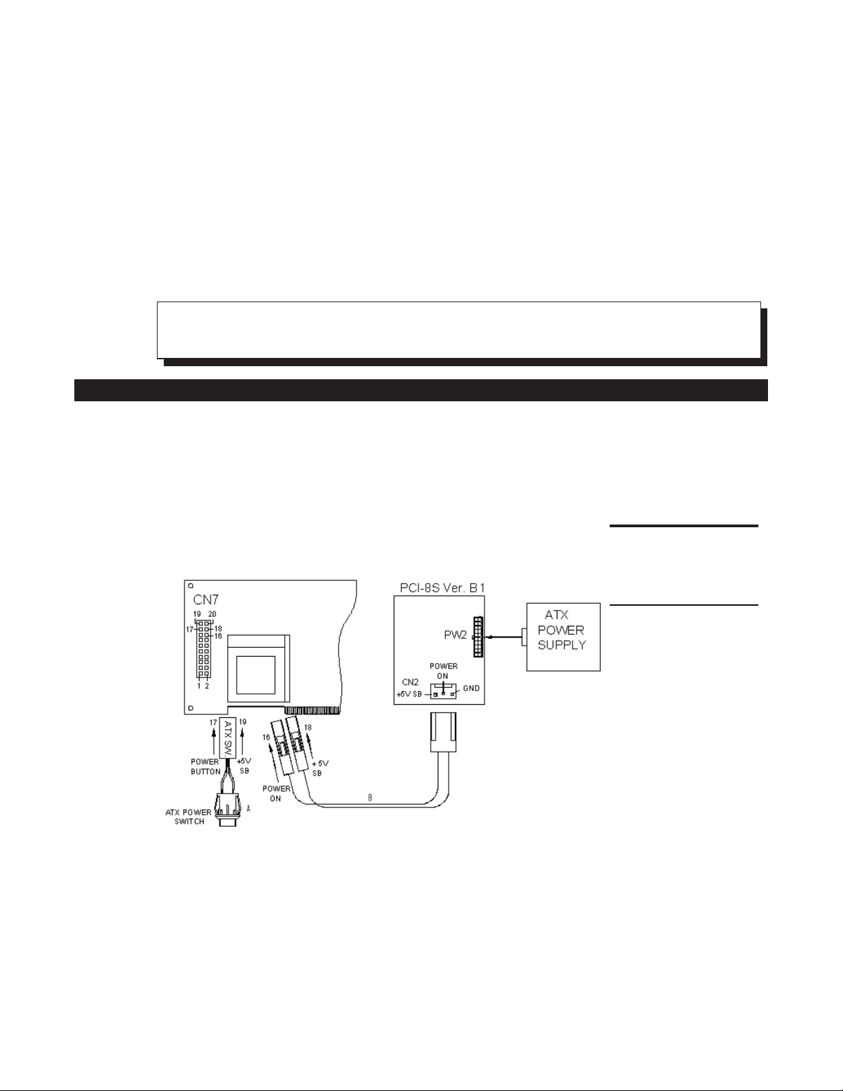
CONNECTING TO AN ATX POWER SUPPLY
To Connect ATX Power Supply to the Backplanes and/or the ISBC Card
1. Disconnect the AC cord from the power supply to prevent sudden electric surge.
2. Connect the ATX power supply switch to the pin 17 (power button) and pin 19
(+5VSB) of CN7 (multi panel) on the board.
Figure 1. SBC-370
(through Power
Button and +5VSB).
•
To turn off the power supply, push the ATX power switch button for about four seconds.
•
To turn the system on, push the button once.
Features 10
Page 10
2 Board Configuration
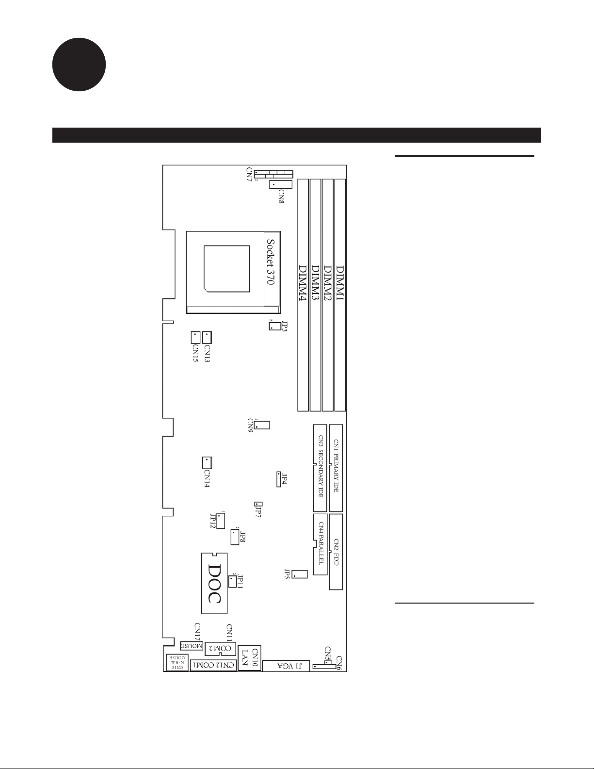
BOARD LAYOUT
Figure 2. SBC-370
Configuration.
JP3, CPU Frequency
JP8, CPU Multiplier Setting
JP5, Watchdog Timer Type
Setting
JP12, Watchdog Timeout Period
JP11, DiskOnChip Memory
Address Setting
JP4, Clear CMOS Setup
JP7, PS/2 Mouse Setting
CN2, Floppy Disk Drive
CN1, Primary IDE
CN3, Secondary IDE
CN4, Parallel Port
CN12, Serial Port 9-pin
D-sub (COM1)
CN11, Serial Port 2x5 pin
header (COM2)
CN8, External Keyboard
CN17, Mouse
CN18, Keyboard/Mouse
CN7, Multi Panel Switch
CN9, USB
CN6, IrDA
J1, VGA
CN10, LAN RJ45
CN5, LED Connector for LAN
CN13, CPU Fan
CN14, System1 Fan
CN15, System2 Fan
DIMM1/2/3/4, DIMM Sockets
Socket 370, Intel Socket 370
Celeron processor
12
Page 11

JUMPERS
The default settings are highlighted in the tables that follow.
CPU Frequency Setting (JP3)
Frequency 1-3 2-4 3-5 4-6
50 MHz OFF OFF ON ON
66 MHz/100 MHz* ON ON OFF OFF
75 MHz OFF ON ON OFF
83.3 MHz ON OFF OFF ON
*Intel Celeron CPU will auto-detect 66 MHz.
* Intel Pentium III (FC-PGA) CPU will auto detect 100MHz.
*Refer to figure 2 for the location of JP3.
CPU Multiplier Setting (JP8)
Ration 1-2 3-4 5-6 7-8
3.0 x ON OFF ON ON
3.5 x ON OFF OFF ON
4.0 x OFF ON ON ON
4.5 x OFF ON OFF ON
5.0 x OFF OFF ON ON
5.5 x OFF OFF OFF ON
6.0xONONONOFF
6.5 x ON ON OFF OFF
7x ON OFF ON OFF
7.5x ON OFF OFF OFF
8x OFF ON ON OFF
Refer to figure 2 for the location of JP8.
Watchdog Timer Type Setting (JP5)
The Watchdog Timer is enabled by reading port 443H. It should be triggered be
fore the timeout period ends; otherwise, it will assume the program operation is
abnormal and will issue a reset signal to reboot or activate NMI to CPU. The
Watchdog Timer is disabled by reading port 043H.
Pin Number Description
1-2 NMI
2-3 RESET
Refer to figure 2 for the location of JP5.
-
Board Configuration 13
Page 12

Watchdog Timeout Period (JP12)
Period 1-2 3-4 5-6 7-8
1 sec. OFF OFF ON OFF
2 sec. OFF OFF ON ON
10 sec. OFF ON OFF OFF
20 sec. OFF ON OFF ON
110 sec. ON OFF OFF OFF
220 sec. ON OFF OFF ON
Refer to figure 2 for the location of JP12.
DiskOnChip™ Memory Address Setting (JP11)
The DiskOnChip™ (DOC) Flash Disk Chip is produced by M-Systems. No extra soft
ware utility is needed because the DOC is 100% compatible to hard disk. It is
"plug and play", easy, and reliable. The DOC is available from 2 MB to 144 MB.
Pin Number Address
1-2 CE00-CFFF
3-4 D600-D7FF
5-6 DE00-DFFF
Refer to figure 2 for the location of JP11.
Clear CMOS Setup (JP4)
If you forget the CMOS password, you can clear or reset it by closing JP4. After
JP4 is closed, turn on the power for about three seconds, then turn it off and
open JP4. Now, the password has been cleared from your CMOS.
Pin Number Description
2-3 Normal Operation
3-4 Clear CMOS Setup
-
Note: 1-4 is for connection with external battery (4=GND)
Refer to figure 2 for the location of JP4.
Board Configuration 14
Page 13

PS/2 Mouse Setting (JP7)
The PS/2 mouse uses IRQ12 while in operation.
JP7 Description
ON Enable the PS/2 Mouse, IRQ12
OFF Disable the PS/2 Mouse
Refer to figure 2 for the location of JP7.
15 Board Configuration
Page 14

CONNECTORS
This section describes how to connect peripherals, switches, and indicators to the
SBC-370.
Floppy Disk Drive Connector (CN2)
The SBC-370 is equipped with a 34-pin daisy-chain drive connector cable. For the
location of this connector, refer to CN2 in figure 2.
Pin Number Description
1 GND
2 REDUCE WRITE
3 GND
4NC
5 GND
6NC
7 GND
8 INDEX#
9 GND
10 MOTOR ENABLE A#
11 GND
12 DRIVE SELECT B#
13 GND
14 DRIVE SELECT A#
15 GND
16 MOTOR ENABLE B#
17 GND
18 DIRECTION#
Pin Number Description
19 GND
20 STEP#
21 GND
22 WRITE DATA#
23 GND
24 WRITE GATE#
25 GND
26 TRACK 0#
27 GND
28 WRITE PROTECT#
29 GND
30 READ DATA#
31 GND
32 SIDE 1 SELECT#
33 GND
34 DISK CHANGE#
Board Configuration 16
Page 15

PCI E-IDE Disk Drive Connector (CN1/CN3)
You can attach four IDE (Integrated Device Electronics) hard disk drives to the
SBC-370 IDE controller.
CN1 (IDE 1): Primary IDE Connector
•
CN3 (IDE 2): Secondary IDE Connector
•
For the location of these connectors, refer to CN1 and CN3 in figure 2.
Pin Number Description
1 RESET#
2 GND
3 DATA 7
4 DATA 8
5 DATA 6
6 DATA 9
7 DATA 5
8 DATA 10
9 DATA 4
10 DATA 11
11 DATA 3
12 DATA 12
13 DATA 2
14 DATA 13
15 DATA 1
16 DATA 14
17 DATA 0
18 DATA 15
19 GND
20 NC
Pin Number Description
21 IDE DRQ
22 GND
23 IOW#
24 GND
25 IOR#
26 GND
27 IDE CHRDY
28 GND
29 IDE DACK
30 GND
31 INTERRUPT
32 NC
33 SA 1
34 NC
35 SA 0
36 SA 2
37 HDC CS0#
38 HDC CS1#
39 HDD ACTIVE#
40 GND
17 Board Configuration
Page 16

Parallel Port (CN4)
This port is usually connected to a printer. The SBC-370 includes an onboard par
allel port accessed through a 26-pin flat-cable connector. For the location of this
connector, refer to CN4 in figure 2.
Pin Number Description
1 STROBE#
2 DATA 0
3 DATA 1
4 DATA 2
5 DATA 3
6 DATA 4
7 DATA 5
8 DATA 6
9 DATA 7
10 ACKNOWLEDGE
11 BUSY
12 PAPER EMPTY
13 PRINTER SELECT
14 AUTO FORM FEED #
15 ERROR#
16 INITIALIZE
17 PRINTER SELECT LN#
18 GND
19 GND
20 GND
21 GND
22 GND
23 GND
24 GND
25 GND
26 NC
-
Board Configuration 18
Page 17

Serial Ports (CN12/CN11)
The SBC-370 offers two high speed NS16C550 compatible UARTs with Read/Re
ceive 16 byte FIFO serial ports (COM1/COM2).
CN12: Serial Port 9-pin D-sub Connector (COM1)
•
Pin Number Description
1 DCD
2RXD
3 TXD
4 DTR
5 GND
6 DSR
7RTS
8 CTS
9RI
CN11: Serial Port 2x5 pin header Connector (COM2)
•
Pin Number Description
1 DCD
2 DSR
3RXD
4RTS
5 TXD
6 CTX
7 DTR
8RI
9 GND
10 NC
-
For the location of these connectors, refer to CN12 and CN11 in figure 2.
19 Board Configuration
Page 18

Keyboard/Mouse Connector (CN8/CN17/CN18)
The SBC-370 provides one external keyboard, one external mouse, and one PS/2
keyboard and mouse connector.
CN8: 5-pin Header External Keyboard Connector (see note below)
•
Pin Number Description
1 KB CLK
2 KB DATA
3NC
4 GND
5 +5V
CN17: PS/2 Mouse 5-pin Header Connector
•
Pin Number Description
1 MS DATA
2NC
3 GND
4 +5V
5MSCLK
CN18: 6-pin Mini-DIN PS/2 Keyboard and Mouse Connector (see note below)
•
Pin Number Description
1 KB DATA
2NC
3 GND
4 +5V
5 KB CLK
6NC
For the location of these connectors, refer to figure 2.
Note: A keyboard cannot be connected to CN8 and CN18 simultaneously. A mouse can
not be connected to CN17 and CN18 simultaneously. One of each device can be con
nected to CN18 via a Y adapter cable) or CN8 and CN17.
-
-
Board Configuration 20
Page 19

External Switches and Indicators (CN7)
There are several external switches and indicators for monitoring and controlling
the CPU board. All the functions are in the CN7 Multi Panel connector. For the lo
cation of this connector, refer to figure 2.
-
Pin Number Description
1 SPEAKER
2 VCC
3NC
4NC
5NC
6 GND
7 +5V
8 KEYLOCK
9 RESET SW
10 GND
USB Port Connector (CN9)
The SBC-370 has two built-in USB ports for future I/O bus expansion. Pins 1, 3, 5,
and 7 for USB 0. Pins 2, 4, 6, and 8 for USB 1. For the location of this connector,
refer to figure 2.
Pin Number Description
1VCC
3 SBD0-
5 SBD0+
7 GND
2 GND
4 SBD1+
6 SBD1-
8VCC
Pin Number Description
11 GND
12 GND
13 IDE LED
14 NC
15 +5V
16 ATX POWER CONTROL
17 ATX POWER BUTTON
18 ATX 5VSB
19 ATX 5VSB
20 ATX 5VSB
21 Board Configuration
Page 20

IrDA Infrared Interface Port (CN6)
The built-in IrDA port supports Serial Infrared (SIR) or Amplitude Shift Keyed IR
(ASKIR) interface. To use the IrDA port, configure the SIR or ASKIR model in the
BIOS's Peripheral Setup's COM2. Then, the normal RS-232 COM2 will be disabled.
For the location of this connector, refer to figure 2.
Pin Number Description
1 VCC
2 FIR-RX
3 IR-RX
4 GND
5IR-TX
6 CIR-RX
VGA Connector (J1)
The built-in 15-pin VGA connector can be connected directly to your monochrome
CRT monitor as well as a high resolution color CRT monitor. For the location of
this connector, refer to figure 2.
Pin Number Description
1RED
2 GREEN
3BLUE
4NC
5 GND
6 GND
7 GND
8 GND
9 VCC
10 GND
11 NC
12 DDC DATA
13 HSYNC
14 VSYNC
15 DDC CLK
Board Configuration 22
Page 21

LAN RJ45 Connector (CN10)
The SBC-370 is equipped with a built-in 10/100Mbps Ethernet Controller. You can
connect it to your LAN through the RJ45 LAN connector. For the location of this
connector, refer to figure 2.
Pin Number Description
1 TX+
2TX-
3. RX+
4. 75 W termination
5. 75 W termination
6. RX-
7. 75 W termination
8. 75 W termination
LED Connector for LAN (CN5)
For the location of this connector, refer to figure 2.
Pin Number Description
1 VCC
2 LAN ACT.
Fan Connector (CN13/CN14/CN15)
The SBC-370 provides one CPU cooling fan connector and two system fan connectors. These connectors can supply 12V/500mA (maximum) to the cooling fan. The
connector has a rotation pin that supplies the fan's rotation signal to the system
so that the system BIOS can read the fan speed. For the location of each connector, refer to figure 2.
•
CN13: CPU Fan Connector
•
CN14: System1 Fan Connector
•
CN15: System2 Fan Connector
Pin Number Description
1 Fan Sensor
2 +12V
3 GND
23 Board Configuration
Page 22

SYSTEM INTERRUPTS (IRQS)
IRQ Description
IRQ0 System Timer
IRQ1 Keyboard
IRQ2 Cascade to IRQ Controller
IRQ3 COM2/COM4
IRQ4 COM1/COM3
IRQ5 Unused
IRQ6 Floppy Drive (FDC)
IRQ7 Printer
IRQ8 Real Time Clock
IRQ9 Unused
IRQ10 Unused
IRQ11 Unused
IRQ12 PS/2 Mouse
IRQ13 FPU
IRQ14 Primary IDE
IRQ15 Secondary IDE
DMA CHANNEL ASSIGNMENTS
Channel Function
0 Available
1 Available
2 Floppy disk ( 8-bit transfer )
3 Available
4 Cascade for DMA Controller 1
5 Available
6 Available
7 Available
Board Configuration 24
Page 23

1ST MB MEMORY ADDRESS MAP
The default setting is highlighted.
Memory Address Description
00000-9FFFF System Memory
A0000-BFFFF VGA Buffer
C0000-CBFFF VGA BIOS
D6000-D7FFF DOC 2000
E0000-FFFFF System BIOS
1000000- Extend BIOS
I/O MAP
I/O Address Range Description
000-01F DMA Controller #1
020-021 Interrupt Controller #1, Master
040-05F 8254 Timer
060-06F 8042 (Keyboard Controller)
070-07F Real time Clock, NMI
080-09F DMA Page Register
0A0-0BF Interrupt Controller #2
0C0-0DF DMA Controller #2
0F0 Clear Math Coprocessor Busy
0F1 Reset Math Coprocessor
0F8-0FF Math Coprocessor
1F0-1F8 Fixed Disk
200-207 Game I/O
278-27F Parallel Printer Port 2 (LPT3)
2E8-2EF Serial Port 4
2F8-2FF Serial Port 2
300-31F Prototype Card
360-36F Reserved
378-37F Parallel Printer Port 1 (LPT2)
380-38F SDLC, Bisynchronous 2
3A0-3AF Bisynchronous 1
3B0-3BF Monochrome Display and
3C0-3CF Reserved
3D0-3DF Color/Graphics Monitor Adapter
3E8-3EF Serial Port 3
3F0-3F7 Diskette Controller
3F8-3FF Serial Port 1
443 Watchdog Timer Enable
043 Watchdog Timer Disable
(non-maskable interrupt) Mask
Printer Adapter (LPT1)
25 Board Configuration
Page 24

3 AMI BIOS Setup Menus
The SBC-370 uses the AMI PCI/ISA BIOS for system configuration. The AMI BIOS
setup program is designed to provide maximum flexibility in configuring the sys
tem by offering various options for end user requirements. This section is pro
vided to assist you in the proper usage of these features.
GETTING STARTED
When you turn the system on, the BIOS will enter the Power-On-Self-Test routines.
These routines will be executed for system test and initialization and system con
figuration verification.
Hit DEL if you want to run SETUP
To access AMI PCI/ISA BIOS Setup program, press the Del key. The following screen
will be displayed at this time.
-
-
-
STANDARD CMOS SETUP
The standard CMOS Setup is used for basic hardware system configuration. The main
26
Page 25

function is for Date/Time setting and Floppy/Hard Disk setting. Refer to the following
screen.
Date/Time:
Use the left arrow, right arrow, and Enter keys to move from one field to the
next. The numeric keys, 0-9, are used to change the field values. To set the date
(MM:DD:YYYY), select one of the fields (Month, Day, or Year) and then press either
PgUp or PgDn to set it to the current Month, Day, and Year. Follow the same procedure
for setting the Time (HH/MM/SS). The hour is calculated according to a 24-hour mili
tary clock, i.e., 00:00:00 through 23:59:59.
Note: It is not necessary to enter the seconds or type zeros in front of numbers.
IDE hard disk drive setup: Use one of the following setup procedures:
•
Use the Auto setting for detection during boot-up.
•
Use the Auto-Detect Hard Disk option in the main menu; the computer will
automatically detect the HDD specifications.
•
Manually enter the specifications from the User option.
ADVANCED CMOS SETUP
The Advanced CMOS Setup is designed for optimizing the performance of the
SBC-370. Under normal operation, you do not have to change any default set
tings. The default settings are preset for the most reliable operation.
-
-
27 AMI BIOS Setup Menus
Page 26

The following screen will be displayed if you select Advanced CMOS Setup:
You can change the value of each option by using the PgUp and PgDn key. The available options are shown on the right side of the screen.
Quick Boot > :
With the Quick Boot set to Enabled, the BIOS will only check the first 1 MB
of the system memory, providing a quick boot when you turn on your computer. With
the Quick Boot
Disabled, the BIOS will test all system memory when it boots up. It will
spend about 40 seconds until it receives a Ready signal from the HDD. It will also wait
for you to press the
1st, 2nd, 3rd Boot Device >: This is used to define the sequence of boot drives after the rou
Del key.
tine check up completes. If the 1st Boot Device fails, the BIOS will attempt to boot from
the 2nd or 3rd device. The Optimal and Fail-Safe default settings are C:, A:, CDROM.
Try Other Boot Devices >: The BIOS will try to boot from any other available device in the
system if the 1st, 2nd, and 3rd device fails to boot.
Floppy Access Control >: This defines the read/write access which is set when booting from
a floppy drive.
Hard Disk Access Control >: This defines the read/write access which is set when booting
from a HDD.
S.M.A.R.T. for Hard Disks >: Allows the BIOS to use the System Management and Reporting
Technologies protocol for reporting server system information on a network.
BootUp Num-Lock >: Turns on/off the Num-Lock option on an enhanced keyboard when
you boot. If you turn it off, the arrow keys on the numeric keypad can be used just as
the other set of arrow keys on the keyboard and vice versa.
AMI BIOS Setup Menus 28
Page 27

Floppy Drive Swap >: This function enables you to swap the floppy disk drives through
software without moving the hardware.
Floppy Drive Seek >: When this option is Enabled, the BIOS will perform a Seek command
on floppy drive A: before boot-up.
PS/2 Mouse Support >: This is used to determine whether or not a PS/2 mouse is supported.
System Keyboard >: Configures the keyboard. If you set it to Absent, the BIOS will not re
-
port keyboard errors.
Primary Display >: Used to define the type of display monitor for the system. The Absent
option is for network file servers.
Password Check >: Used to define whether or not a password is necessary for access to the
BIOS setup.
Boot to OS/2 >: If you run the OS/2 operating system, this option must be set to Yes, per
mitting the BIOS to run properly if OS/2 or any other OS that does not support Plug
and Play is found in your computer.
CPU Serial Number> : This option is available only if you use a Pentium® III processor.
Cache Bus ECC >: This option is available only if you use a Pentium® III processor.
System BIOS Cacheable >: Used to define whether or not the memory segment FOOOH can
be read from or written to cache memory. Setting it to
Enabled will provide faster execu-
tion in your system.
XXXX, 16k Shadow >: ROM Shadow is a technique in which BIOS code is copied from
slower ROM to faster RAM. If you enable it, the BIOS will be executed from the RAM.
Each option allows 16 K segment to be shadowed to the RAM.
29 AMI BIOS Setup Menus
Page 28

ADVANCED CHIPSET SETUP
These setup functions are working mostly for Chipset (Intel 440BX). These op
tions are used to change the Chipset's registers. Carefully change any default set
ting, otherwise the system will run unstably.
-
-
Configure SDRAM Timing by SPD >:
parameters. When
SDRAM RAS# to CAS Delay >: Used to specify the relative delay between row and column ad
Disabled, chipset parameters return to setup information stored in CMOS.
Enabled will select predetermined optimal values of chipset
dress strobe from SDRAM.
SDRAM RAS# Precharge >: This option specifies the length of time for Row Address Strobe
from SDRAM to precharge.
SDRAM CAS# Latency >: Used to specify the CAS latency timing from SDRAM DRAM.
DRAM Integrity Mode >: Used to choose DRAM Integrity Mode; ECC/EC will enable the Error
Checking and Correction DRAM integrity mode.
DRAM Refresh Rate >: Used to specify the timing for DRAM Refresh.
Memory Hole >: Used to specify the location of a memory hole in the CMOS RAM. This set
ting reserves 15 to 16 MB memory address space for ISA expansion cards that specifi
cally require this setting. Memory from 15 MB and up will be unavailable to the system
because expansion cards can only access memory up to 16 MB.
VGA Frame Buffer USWC >: Used to specify whether or not a caching of the video A000-BFFF
RAM is allowed.
Enabled will provide better system performance.
-
-
AMI BIOS Setup Menus 30
Page 29

PCI Frame Buffer USWC >: Used to specify whether or not a caching of the PCI VGA frame
buffer is allowed.
USWC Write Post >: Enable or disable the use of Uncacheable, Speculatable, Write-Com
-
bined memory.
Graphics Aperture Size >: Define the size of Graphics Aperture.
Search for MDA Resources >: Allows the BIOS to search for MDA resources when Yes is specified.
8bit I/O Recovery Time >: Define the length of time for 8 bit I/O recovery.
16bit I/O Recovery Time >: Define the length of time for 16 bit I/O recovery.
USB Passive Release >: Specify whether or not PIIX4 is allowed to use Passive Release
while transferring control data for USB transactions.
PIIX4 Passive Release >: PIIX4 points to the Intel 82371AB PCI/ISA/IDE Xcelerator chip. Set
ting this option to
PIIX4 Delayed Transaction >: Used to enable or disable the embedded 32-bit posted write
Enabled will prioritize PCI at the top, then IDE and ISA.
buffer, which supports delay transaction.
USB Function >: Enable or disable the USB (Universal Serial Bus) functions.
-
31 AMI BIOS Setup Menus
Page 30

POWER MANAGEMENT SETUP
Power Management/APM >: Enables or disables the Advanced Power Management feature.
Green PC Monitor Power State >: Specify the power state of the monitor after the specified pe-
riod of display-idle has ended.
Video Power Down Mode >: Specify the power state of the VESA VGA video subsystem after
the specified period of display-idle has ended.
Hard Disk Power Down Mode >: Specify the power state of the hard disk after the specified pe
riod of hard drive-idle has ended.
Standby Time Out (Minute) >: Specify the length of the system-idle period while the system is
in full power-on state. After this period of time has ended, the system will go into
Standby state.
Suspend Time Out (Minute) >: Specify the length of the system-idle period while the system is in
Standby state. After this period of time has ended, the system will go into Suspend state.
Throttle Slow Clock Ratio >: Specify the speed of the system clock under power saving state.
The figure is a ratio between power conserving and normal state CPU clock.
Modem Use IO Port >: Assign a port for modem.
Modem Use IRQ >: Assign an IRQ for modem.
Display Activity >: Specify if the BIOS should monitor display activity or not.
-
Device X >: Used to monitor or ignore specified device IRQs.
AMI BIOS Setup Menus 32
Page 31

PCI/PLUG AND PLAY SETUP
This setup handles the SBC-370 PCI function. All PCI bus slots on the system use
INTA#, thus all installed PCI slots must be set.
Plug and Play Aware O/S >:
OS when the setting is
of interrupt settings, set the setting to
Clear NVRAM >: Specify whether or not the BIOS will clear NVRAM on every boot.
PCI Latency Timer (PCI Clocks) >: Define the latency timing (PCI clock) for all PCI devices on
When PNP OS is installed, interrupts will be reassigned by the
Yes. When a non-PNP OS is installed or to prevent reassigning
No.
the PCI bus.
PCI VGA Palette Snoop >: This option is useful only for a system with more than one VGA
device connected to it through different bus (one PCI and one ISA). To enable those
various VGA devices to handle signals from the CPU on each set of palette registers of
every video device, it must be set to
Enabled.
Note: If another PCI or ISA video card is needed other than the onboard VGA, set PCI
VGA Palette Snoop
video card when
Allocate IRQ to PCI VGA >: To allocate IRQ to PCI VGA, select Yes.
PCI IDE BusMaster >: Used to include the BusMastering capability into the IDE Controller
on the PCI.
to Enabled. The system will automatically recognize and use the additional
Enabled.
33 AMI BIOS Setup Menus
Page 32

Offboard PCI IDE Card >: This function is used to specify whether or not an offboard PCI
IDE card is installed in your computer. You must specify the slot number on the board
which will be used for the card.
Offboard PCI IDE Primary (/Secondary) IRQ >: Specify the PCI interrupt that is assigned to the Pri
mary (/Secondary) IDE channel on the offboard PCI IDE controller.
PCI Slot (1,2,3,4) IRQ Priority >: Specify the IRQ priority to be used by the PCI devices on slots
1to4.
DMA Channel (0,1,3,5,6,7) >: Used to indicate whether or not the DMA channel is assigned for
a PnP or ISA card.
IRQ (3,4,5,7,9,10,11,14,15) >: Assign the displayed IRQ to be used by a legacy ISA adapter
card. The settings are
PERIPHERAL SETUP
This setup works mostly on Multi-I/O Chip (W83977F). The options are used to
change the Chipset's registers. Carefully change any default setting to meet your
application needs. The only concern is Onboard Serial Port 2. If you want to use
the IrDA port, you have to configure the SIR or ASKIR model in the BIOS's Periph
eral Setup's COM2; the RS-232 COM2 will be disabled.
-
ISA/EISA or PCI/PnP.
-
Onboard FDC >:
Used to enable the FDC on your board. If you set it to Auto, the BIOS will
automatically decide if the FDC should be enabled.
Onboard Serial Port A (/B) >: Specify the I/O port address of the serial port 1(/2). If you set it
Auto, the BIOS will decide the correct I/O port address automatically.
to
AMI BIOS Setup Menus 34
Page 33

Serial Port B Mode >: Specify the mode of serial port 2.
IR Duplex Mode >: Specify the mode of IR device that is connected to the IR port.
IrDA Protocol >: Specify the function mode if an IrDA mode is selected.
Onboard Parallel Port >: Specify the I/O port address of the parallel port.
Parallel Port Mode >: Used to specify the mode of parallel port. The options are:
Normal
•
Bi-Dir
•
EPP
•
ECP
•
Parallel Port IRQ >: This option is used to assign certain IRQ to the parallel port. The opti
(normal parallel port mode)
(supports bidirectional transfer)
(supports devices that comply with the Enhanced Parallel Port specification)
(supports devices that comply with the Extended Capabilities Port)
mal and fail-safe setting is 7.
Parallel Port DMA Channel >: This function is available only if the parallel port mode is ECP.
The optimal and fail-safe setting is 3.
Onboard IDE >: Define which onboard IDE controller channel(s) should be used. Avail
able options are:
Primary, Secondary, Both,andDisabled.
-
-
35 AMI BIOS Setup Menus
Page 34

HARDWARE MONITOR SETUP
There is a LM78 chip that can monitor onboard system voltage and fan speed.
The voltage monitoring will cover +5V, +12V, -12V, and -5V.
Note: Normal CPU fan RPM is more than 5000 RPM. If your CPU fan RPM is less than
5000 RPM, something is wrong and the CPU will be in overheat condition. Make sure
that the connection at CN12/CN13 is correct.
AMI BIOS Setup Menus 36
Page 35

CHANGE SUPERVISOR/USER PASSWORD
Set a password that is used to protect your system and Setup Utility. Supervisor
Password has higher priority than User Password. Once you setup the password,
the system will ask you to enter the password every time you enter the BIOS SETUP.
If you enter the BIOS SETUP with the Supervisor Password, you can access every
setup option on the main menu. With a User Password, you can only choose three
setup options (Change User Password, Save Setting and Exit, and Exit Without Saving). To disable
these passwords, enter the BIOS SETUP menu with the Supervisor Password and
then press the Enter key instead of entering a new password when the Enter Password
prompt appears.
AUTO-DETECT HARD DISK
This option detects the parameters of an IDE hard disk drive (HDD sector, cylin
der, head, etc.) automatically and will put the parameters into the Standard
CMOS Setup screen. Up to 4 IDE drives can be detected and the parameters will
be listed in the box. Press Y if you accept these parameters. Press N to skip to the
next IDE drive.
Note: If your IDE HDD was formatted in a previous system, incorrect parameters may
be detected. In this case, you need to enter the correct parameters manually or low-level
format the disk.
-
37 AMI BIOS Setup Menus
Page 36

AUTO CONFIGURATION WITH OPTIMAL SETTINGS
This option lets you load the Optimal default settings. These settings are
best-case values that will provide the best performance. Whenever your CMOS
RAM is damaged, the Optimal settings will be loaded automatically.
AMI BIOS Setup Menus 38
Page 37

AUTO CONFIGURATION WITH FAIL SAFE SETTINGS
This option allows you to load the Fail Safe default settings when your computer
cannot boot normally. These settings are not optimal, but are the most stable.
SAVE SETTINGS AND EXIT
Select this option when you finish setting all the parameters and want to save
them into the CMOS. Simply press the Enter key and all the configuration changes
will be saved.
EXIT WITHOUT SAVING
Select this option if you want to exit the Setup without saving the changes that you
made. Simply press the Enter key and you will exit the BIOS SETUP without saving the
changes.
39 AMI BIOS Setup Menus
Page 38

Index
A
advanced chipset setup ................ 30
advanced CMOS setup ................ 28
allocate IRQ to PCI VGA ............... 33
ATX power supply, connecting ............ 10
auto configuration with fail safe settings ....... 39
auto configuration with optimal settings ....... 38
auto-detect hard disk ................. 37
B
BIOS main setup menu ................ 26
advanced chipset setup .............. 30
advanced CMOS setup .............. 28
auto configuration with fail safe settings ..... 39
auto configuration with optimal settings ..... 38
auto-detect hard disk ............... 37
change supervisor password ........... 37
change user password .............. 37
exit without saving ................ 39
hardware monitor setup ............. 36
PCI/plug and play setup.............. 33
peripheral setup ................. 34
power management setup ............ 32
save settings and exit ............... 39
standard CMOS setup............... 27
board layout ...................... 12
boot device, 1st, 2nd, 3rd ............... 28
boot to OS/2 ..................... 29
bootup num-lock ................... 29
C
cache bus ECC .................... 29
clear CMOS setup ................... 14
clear NVRAM...................... 33
connector
fan......................... 23
floppy disk drive ................. 16
IrDA infrared interface .............. 22
keyboard ..................... 20
keyboard/mouse ................. 20
LAN RJ45 ..................... 23
LEDforLAN.................... 23
mouse ....................... 20
multi panel .................... 21
parallel ...................... 18
PCI E-IDE disk driver ............... 17
serial........................ 19
USB port ..................... 21
VGA........................ 22
connectors....................... 16
CPU frequency setting ................. 13
CPU multiplier setting................. 13
CPU serial number .................. 29
D
date, setting ...................... 27
device x ........................ 32
disable VGA ...................... 33
DiskOnChip memory address setting ......... 14
display activity .................... 32
DMA channel (0,1,3,5,6,7) .............. 34
DMA channel assignments .............. 24
DRAM integrity mode ................. 30
DRAM refresh rate .................. 30
E
exit without saving .................. 39
external switches and indicators ........... 21
F
fan connector ..................... 23
features ......................... 6
floppy access control ................. 28
floppy disk drive connector .............. 16
floppy drive seek ................... 29
floppy drive swap ................... 29
G
graphics aperture size ................ 31
green PC monitor power state ............ 32
H
hard disk access control ............... 28
hard disk power down mode ............. 32
hardware monitor setup ............... 36
I
I/Omap........................ 25
I/O recovery time
16bit....................... 31
8bit........................ 31
IDE hard disk drive setup ............... 27
IDE, onboard ..................... 35
IR duplex mode .................... 35
IrDA infrared interface port .............. 22
IrDA protocol ..................... 35
IRQ (3,4,5,7,9,10,11,14,15) .............. 34
IRQs .......................... 24
J
jumper
clear CMOS setup ................. 14
CPU frequency setting .............. 13
40
Page 39

CPU multiplier setting .............. 13
DiskOnChip memory address setting....... 14
PS/2 mouse setting ................ 15
watchdog timeout period ............. 14
watchdog timer type setting ........... 13
jumpers ........................ 13
K
keyboard connector .................. 20
keyboard/mouse connector .............. 20
L
LAN RJ45 connector .................. 23
LED connector for LAN ................ 23
M
memory hole ..................... 30
memory map ..................... 25
modem use IO port .................. 32
modem use IRQ .................... 32
mouse connector ................... 20
O
offboard PCI IDE card ................ 34
offboard PCI IDE primary (/secondary) IRQ ..... 34
onboard FDC ..................... 34
P
parallel port ...................... 18
parallel port DMA channel .............. 35
parallel port IRQ ................... 35
parallel port mode .................. 35
parallel port, onboard ................ 35
password
supervisor ..................... 37
user ........................ 37
password check .................... 29
PCI E-IDE disk drive connector ............ 17
PCI frame buffer USWC ................ 31
PCI IDE busmaster .................. 33
PCI latency timer (PCI clocks) ............ 33
PCI slot (1,2,3,4) IRQ priority ............ 34
PCI VGA palette snoop ................ 33
PCI/plug and play setup ................ 33
peripheral setup .................... 34
PIIX4 delayed transaction ............... 31
PIIX4 passive release ................. 31
plug and play aware O/S ............... 33
power management setup............... 32
power management/APM ............... 32
primary display .................... 29
PS/2 mouse support .................. 29
S
S.M.A.R.T. for hard disks................ 29
save settings and exit ................. 39
SDRAM CAS# latency ................. 30
SDRAM RAS# precharge ............... 30
SDRAM RAS# to CAS delay .............. 30
SDRAM timing by SPD ................ 30
search for MDA resources ............... 31
serial port A (/B), onboard .............. 34
serial port B mode................... 35
serial ports ...................... 19
standard CMOS setup ................. 27
standby time out (minute) .............. 32
suspend time out (minute) .............. 32
system BIOS cacheable ................ 29
system interrupts ................... 24
system keyboard ................... 29
T
throttle slow clock ratio ............... 32
time, setting ...................... 27
try other boot devices ................. 28
U
USB function ..................... 31
USB passive release .................. 31
USB port connector .................. 21
USWC write post ................... 31
V
VGA connector .................... 22
VGA frame buffer USWC................ 30
VGA, disable ...................... 33
video power down mode ............... 32
W
watchdog timeout period ............... 14
watchdog timer ..................... 9
watchdog timer type setting.............. 13
Q
quick boot ....................... 28
R
ROM shadow ..................... 29
41
Page 40

139908(D)
Xycom Automation, Inc.
734-429-4971 • Fax: 734-429-1010
http://www.xycom.com
Canada Sales: 905-607-3400
Northern Europe Sales: +44-1604-790-767
Southern Europe Sales: +39-011-770-53-11
 Loading...