

Page 1

June 2016
Getting Started with the
®
Intel
Server Board S1200RP
UEFI Development Kit
Page 2

Intel® Server Board S1200RP UEFI Development Kit
Getting Started with the
Legal Information
INFORMATION IN THIS DOCUMENT IS PROVIDED IN CONNECTION WITH INTEL PRODUCTS. NO LICENSE, EXPRESS OR IMPLIED,
BY ESTOPPEL OR OTHERWISE, TO ANY INTELLECTUAL PROPERTY RIGHTS IS GRANTED BY THIS DOCUMENT. EXCEPT AS
PROVIDED IN INTEL’S TERMS AND CONDITIONS OF SALE FOR SUCH PRODUCTS, INTEL ASSUMES NO LIABILITY WHATSOEVER,
AND INTEL DISCLAIMS ANY EXPRESS OR IMPLIED WARRANTY, RELATING TO SALE AND/OR USE OF INTEL PRODUCTS
INCLUDING LIABILITY OR WARRANTIES RELATING TO FITNESS FOR A PARTICULAR PURPOSE, MERCHANTABILITY, OR
INFRINGEMENT OF ANY PATENT, COPYRIGHT OR OTHER INTELLECTUAL PROPERTY RIGHT. Intel products are not intended for
use in medical, life saving, or life sustaining applications.
Intel may make changes to specifications and product descriptions at any time, without notice.
Designers must not rely on the absence or characteristics of any features or instructions marked “reserved” or “undefined.” Intel
reserves these for future definition and shall have no responsibility whatsoever for conflicts or incompatibilities arising from
future changes to them.
This product may contain design defects or errors known as errata which may cause the product to deviate from published
specifications. Current characterized errata are available on request.
Code Names are only for use by Intel to identify products, platforms, programs, services, etc. (“products”) in development by
Intel that have not been made commercially available to the public , i.e., announced, launched or shipped. They are never to be
used as “commercial” names for products. Also, they are not intended to function as trademarks.
Contact your local Intel sales office or your distributor to obtain the latest specifications and before placing your product order.
Intel, Intel Core, and the Intel logo are trademarks or registered trademarks of Intel Corporation or its subsidiaries in the United
States and other countries.
*Other names and brands may be claimed as the property of others.
Copyright © 2016, Intel Corporation. All rights reserved.
ii June 2016
Page 3

Before You Begin
Contents
1 Before You Begin .............................................................................................. 1
1.1 The Development Kit .............................................................................. 1
1.2 Requirements ........................................................................................ 1
1.3 Supported and recommended hardwar e c o mponents ................................... 2
1.4 Using a SPI flash programmer .................................................................. 3
1.5 Jumper Settings for Management Controllers .............................................. 4
1.6 Legacy BIOS Support .............................................................................. 4
1.7 Network Boot Features ............................................................................ 5
2 Firmware Upgrade Process ................................................................................. 7
2.1 Firmware Upgrade .................................................................................. 7
2.2 Capsule Update ...................................................................................... 8
2.3 USB Firmware Recovery .......................................................................... 9
2.4 Firmware Installation (Socketed SPI Flash) ................................................ 9
2.5 Firmware Installation (Soldered SPI Flash) ............................................... 10
3 User and Reference Documentation ................................................................... 13
Figures
Tables
Figure 1 - Intel Server Board S1200V3RPS ........................................................... 1
Figure 2 - Jumper Block and Motherboard Headers ................................................ 4
Figure 3 - Recovery Jumper and SPI Device Locations ............................................ 7
Table 1 Supported Hardware and Firmware Components ........................................ 2
Table 2 Recommended Hardware Components ...................................................... 3
Getting Started Guide iii
Page 4

Intel® Server Board S1200RP UEFI Development Kit
Getting Started with the
iv June 2016
Page 5
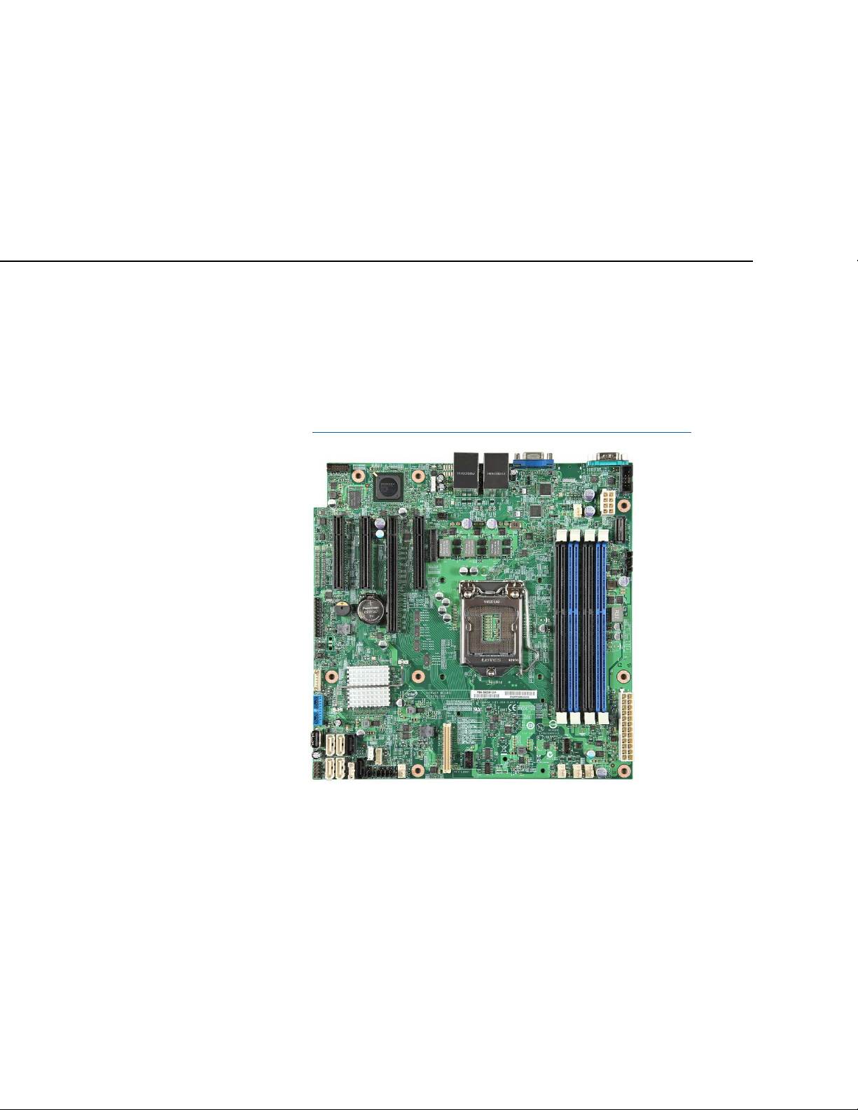
This guide provides an overview of how to upgrade or install the developer platform
UEFI firmware image on an Intel® Server Board S1200RP UEFI Development Kit.
1.1 The Development Kit
The development kit helps engineers design, test, and debug U n i f ied Extensible
Firmware Interface (UEFI) drivers and applications on a UEFI compliant system. You
can download firmware and documentation from the Intel® Architecture Firmware
Resource Center: https://firmware.intel.com/develop/server-development-kit
1
Before You Begin
.
1.2 Requirements
Before upgrading or installing a UEFI compliant firmware image on your development
kit, you need the following skills, components, and tools:
• Intel® Server Board S1200RP UEFI Development Kit target system,
assembled with components from the supported hardware component list.
• PC assembly skills.
Figure 1 - Intel Server Board S1200V3RPS
Page 6
Intel® Server Board S1200RP UEFI Development Kit
Getting Started with the
• USB FAT-formatted flash drive.
• SPI flash programmer with software utility (optional).
• Host PC with Microsoft Windows* operating system (optional, for SPI flash).
You must use one of the supported firmware images included in this development kit:
• SDV_RP_B6_release.rom/.cap – The release version of the firmware, with
debugging features disabled. This is the recommended firmware image.
• SDV_RP_B6_debug.rom/.cap – The debug version of the firmware, with debug
output redirected to the serial port (COM1).
• SDV_RP_B6_srcdbg.rom/.cap – The source level debug version of the
firmware, which supports the Intel
®
UEFI Development Kit Debugger Tool using
the serial port (COM1). This image is recommended only for advanced debugging.
• FVMAIN.fv – The USB recovery firmware image, based on the release firmware.
The development kit also includes:
• Update Utilities for the UEFI Shell: FvUpdate_S1200RP.efi &
CapsuleApp.efi
• User documentation, including this guide and the release notes.
1.3 Supported and recommended hardware components
Table 1 and Table 2 describe the supported and recommended PC hardware
components (respectively) for the Intel® Server Board S1200RP UEFI Development
Kit.
You must use the motherboard and processor listed in the table with the firmware
images provided with the development kit.
Table 1 Supported Hardware and Firmware Components
Hardware and
Firmware
Intel® Server
Board S1200RP
Intel® Xeon®
Processor E3-1275
v3
Intel® Server
Board S1200RP
UEFI Development
Kit firmware image
• You must use the commercially av ailable
S1200V3RPS or Intel® Server Board S1200V3RPL. This document
is based on the Intel® Server Board S1200V3RPS.
• You must use the Intel® Xeon® Processor E3-1275 v3
sink. This processor is avai lable commercially .
• You must use one of the firmware images from the Intel® Server
Board S1200RP UEFI Development Kit. The firmware images in the
development kit have been validated to work only with the specific
processor and motherboards listed above.
Notes
Intel® Server Board
with heat
2 June 2016
Page 7

Before You Begin
Table 2 Recommended Hardware Components
Recommended
Hardware
16GB (2 x 8GB)
DDR3 1333
memory
Power supply
(550W minimum)
SATA HDD 500GB
SATA DVD-RW
Optical Disk Drive
or other install
media
Compatible Chassis
USB keyboard and
USB mouse
Monitor (VGA)
• The Intel® Server Board S1200V3RPS supports up to 32 GB RAM.
• Use at least 16 GB DDR3 memory in the development kit.
• A power supply that meets the requirements of the Intel Server
Board S1200V3RPS is adequate.
• The minimum rating is 550 W. Consider ordering a complete system
from Hard Drives Northwes t
appropriate chassis and power supply.
• Install a hard drive that has at least 500 GB.
• Testing hard drives over 2.2TB requires the use of UEFI.
• Make sure you have a DVD drive or other media (such as a network
connection or USB drive) appropriate for installing the operating
system.
• A chassis is recommended, but not required.
• Including a USB keyboard and mouse with the developer's platform
allows you to input UEFI shell commands and navigate firmware
setup menus.
• A monitor is recommended to enable viewing console output.
Notes
so that the board is packaged with an
Installing the firmware image on an unsupported motherboard may render the Note:
motherboard unusable until it is re-flashed with a backup copy of the
motherboard's original firmware. Use only supported components with the Intel®
Server Board S1200RP UEFI Development Kit.
1.4 Using a SPI flash programmer
The SPI flash programmer is optional, but may be needed to reflash the firmware
image. This is because the development and testing of pre-production products can
corrupt the flash image. If the flash image becomes corrupted, you may need to
perform a hardware-based reprogramming of the SPI flash part.
To reprogram the SPI flash part, you need a third-party SPI flash programmer and the
corresponding software application. These elements allow you to transfer the firmware
image from the host PC to the SPI memory device on the firmware developer platform
(the target PC).
SPI reflash instructions in this document are based on products from DediProg
Technology Co, Ltd.*, which have been verified to work with the supported hardware.
Getting Started Guide 3
Page 8

Intel® Server Board S1200RP UEFI Development Kit
Getting Started with the
1.5 Jumper Settings for Management Controllers
The Intel® Server Board S1200V3RPS is equipped with sever al server ma n agem en t
featured that may need to be disabled for software development and validation.
Disabling the Baseboard Management Controller (BMC) and Manageability Engine (ME)
will disable watchdog timers, which reduces the chance of the system resetting when
debugging firmware.
We recommend the following settings on the Intel® Server Board S 1200V 3RPS:
• Jumper J3K2 – position 2-3 (ME Force Update, Enabled)
• Jumper J3K6 – position 2-3 (BMC Force Update, Enabled)
Please refer to Figure 2
for motherboard jumper settings.
Figure 2 - Jumper Block and Motherboard Headers
1.6 Legacy BIOS Support
The Compatibility Support Module (CSM) can be enabled or disabled through setup:
4 June 2016
Page 9

Before You Begin
EDKII Menu -> Boot Options -> CSM Control
Use the [F2] key to enter setup when booting the system.
This setting lets you manage legacy BIOS support for UEFI Class 2 (CSM Enabled) and
UEFI Class 3 (CSM Disabled) systems. The default setting (Disabled) is recommended
for testing UEFI drivers and operating systems. While testing, this setting will reveal
any unintended dependencies on legacy BIOS calls.
1.7 Network Boot Features
The Intel® Server Board S1200RP UEFI Development Kit supports Pre-Execution
Environment (PXE) boot for IPV4 and IPV6 networking using on-board and add-in
networking devices. Because of added initialization time, network boot for the four onboard networking devices is disabled by default in firmware setup.
Users can enable PXE boot for on-board networking by enabling the ’EFI Network’
setting in the firmware setup menu.
EDKII Menu -> Advanced -> Network Configuration
As of SDV.RP.B6, the Intel® Server Board S1200RP UEFI Development Kit supports
UEFI HTTP and HTTPS boot. These features are described in whitepapers located on
the Tianocore github wiki:
https://github.com/tianocore/tianocore.github.io/wiki/EDK%20II%20White%20papers
Getting Started Guide 5
Page 10

Intel® Server Board S1200RP UEFI Development Kit
Getting Started with the
6 June 2016
Page 11

Firmware Upgrade Process
2
Firmware Upgrade Process
If you have a system running properly on an older version of the Intel® Server Board
S1200RP UEFI Development Kit firmware, you can upgrade the firmware image. This
is supported for platforms with socketed SPI flash devices or SPI flash devices
soldered at the factory.
If your system isn’t running properly, follow the firmware installation process (Section
2.4 or Section 2.5) using the SPI programmer. The full installation procedure takes
between five and thirty minutes.
You must identify key elements on the Intel® Server Board S1200V3RPS in order to
update or install a firmware image.
Figure 3 - Recovery Jumper and SPI Device Locations
2.1 Firmware Upgrade
The FvUpdate_S1200RP.efi utility updates the firmware from the UEFI Shell. You do
not need a hardware-based SPI programmer for this update.
Getting Started Guide 7
Page 12

Intel® Server Board S1200RP UEFI Development Kit
The general steps are:
1. Download the development k it firmware images, firmware update tool, and user
documentation: https://firmware.intel.com/develop/server-development-kit
2. Power up the target PC and boot to the UEFI shell.
3. Use the UEFI shell firmware update util ity (FvUpdate_S1200RP.efi) to apply the
new firmware image to the motherboard’s SPI memory devi ce:
FvUpdate_S1200RP SDV_RP_B6_release.rom
The system shuts down after the update has been applied, and then performs Note:
one configuration cycle on the first boot. Please wait for this cycle to complete
before entering setup or booting to an operating system.
Upgrading the flash will restore Setup and Boot Manager settings to default Note:
values. Any previous changes to Setup or Boot Manager values will be cleared in
the upgrade process. This includes boot entries created by a UEFI-complaint OS.
4. After the platform resets, verif y that the firmware functions correctly by
Entering setup
Verifying the version string matches the expected value for the new firmware
Booting to the UEFI shell
Getting Started with the
.
Once a BIOS update is verified, the Intel® Server Board S1200RP UEFI Development
Kit is ready for use in UEFI development.
Detailed steps for this procedure are explained in the Intel® Server Board S1200RP
UEFI Development Kit Firmware Installation Guide.
2.2 Capsule Update
The capsule update procedure uses software utility to update the system firmware via
the UEFI UpdateCapsule() function. This method is similar to the Firmware Upgrade
method, except UEFI NVRAM Variables are not modified. This process uses the .CAP
firmware file instead of the .ROM file.
1. Download the development k it firmware images, update tool, and user
documentation from https://firmware.intel.com/develop/server-development-kit.
2. Power up the target PC and boot to the UEFI shell.
3. Use the UEFI shell firmware update util ity (CapsuleApp.efi) to start the capsule
update process: CapsuleApp.efi SDV_RP_B6_release.cap
4. The system will start the capsule update process, which resets the system,
displays the boot logo during the update process, then resets the system again
after the update has been applied.
[CAUTION] Do not shut down or reset the platform during the capsule update Note:
process. Interrupting the capsule update may corrupt the system firmware.
8 June 2016
Page 13

Firmware Upgrade Process
2.3 USB Firmware Recovery
The firmware recovery procedure allows the user to recover partially corrupted system
firmware. The firmware is loaded from a FAT32 formatted USB drive by a built-in
recovery routine. We recommend this procedure for recovering systems that fail to
boot after an attempted firmware upgrade or capsule update.
1. Download the development k it firmware images, update tool, and user
documentation from https://firmware.intel.com/develop/server-development-kit
2. Power off the target PC and disconnect the power cord.
3. Open the case of the target PC and locate the Jumper J2K8 (see Figure 3
the jumper from “normal mode” (pins 1-2) to “recovery mode” (pins 2-3).
4. Copy the followin g files to the root folder of a FAT32 formatted USB drive:
FVMAIN.FV
FvUpdate_S1200RP.efi
FvUpdate_S1200RP SDV_RP_B6_release.rom
5. Insert the USB drive into an open USB port on the target PC.
6. Connect the power cord on the target PC and turn the system on. The system
automatically enters recovery mode, which attempts to load firmware from
FVMAIN.FV on the USB drive. This may take several minutes to complete.
7. Once the boot screen appears, enter setup and launch th e UE FI S h ell.
8. Use the UEFI shell firmware update util ity (FvUpdate_S1200RP.efi) to apply the
release firmware image to the motherboard’s SPI memory device:
.
). Move
FvUpdate_S1200RP SDV_RP_B6_release.rom
9. The system will reboot after programming. After reboot, power off the target PC
and disconnect the power cord. Remove the USB drive and return the recovery
jumper to its original position.
10. Power on the target PC. Verify that the firmware functions correctly by entering
setup, verifying the version string matches the expected value for the new
firmware version, and booting to the UEFI shell.
The system shuts down after the update has been applied, then performs one Note:
configuration cycle on the first boot. Wait for this cycle to complete before
entering setup or booting to an operating system.
Upgrading the flash will restore Setup and Boot Manager settings to default Note:
values. Any values previously changed in Setup or Boot Manager will be cleared in
the upgrade process. This includes any boot entries created by a UEFI OS.
2.4 Firmware Installation (Socketed SPI Flash)
This board will not function if the SPI devices are improperly reinstalled. Note:
The complete firmware installation procedure requires the hardware-based SPI flash
programmer. General steps for a complete firmware installation are:
Getting Started Guide 9
Page 14

Intel® Server Board S1200RP UEFI Development Kit
1. Download the development kit firmware images, firmware update tool, and user
documentation from https://firmware.intel.com/develop/server-development-kit
2. Download and install the DediProg software on the host PC.
3. Remove the S PI m em o r y dev ice from the motherboard SPI socket. The SPI device
is located near the SAS_MOD slot at the front of the motherboard.
4. Insert the SPI device into the SPI programmer’s 8-pin socket adapter.
5. Use the DediProg Engineering utility to create a backup copy of the SPI device.
6. Erase the existing firmware from the SPI device.
7. Write one of the development kit firmware images to the SPI device
(SDV_RP_B6_release.rom, SDV_RP_B6_debug.rom or SDV_RP_B6_srcdbg.rom).
8. Remove the SPI flash device from the DediProg SPI socket and reinstall it in the
SPI socket.
9. Reassemble the target PC.
The system performs one configuration cycle on the first boot. Wait for this Note:
cycle to complete before entering the UEFI Shell.
10. After the platform resets, verify that the firmware functions correctly by entering
setup and booting to the UEFI shell.
Getting Started with the
.
Once a firmware update is verified, the Intel® Server Board S1200RP UEFI
Development Kit is ready for use in UEFI development.
Detailed steps for this procedure are explained in the Intel® Server Board S1200RP
UEFI Development Kit Firmware Installation Guide.
2.5 Firmware Installation (Soldered SPI Flash)
The firmware installation procedure requires a hardware-based SPI flash programmer
clip adapter for the 8-pin SPI device and does not work with a socketed SPI part. Use
the instructions in Section 2.4 for motherboards with socketed SPI flash devices.
General steps for a complete firmware installation are:
11. Download the development kit firmware images, firmware update tool, and user
documentation from https://firmware.intel.com/develop/server-development-kit
12. Download and install the DediProg software on the host PC.
13. Attach the DediProg S08 test clip to the SPI device.
14. Power on the target PC and boot to the UEFI Shell.
15. Power off the target PC using the power button (hold for four seconds until the
processor fan stops). The PC power supply should still be on (motherboard’s blue
and green LEDs are on) but the system is not on.
16. Start the DediProg Engineering utility, which will detect the SPI device.
.
The DediProg S08 test clip must be seated and make proper contact with the Note:
SPI device for reliable detection and programming. If the SPI device is not
detected, check the position of the test clip and retry.
10 June 2016
Page 15

Firmware Upgrade Process
17. Use the DediProg software utility to create a backup copy of the SPI device.
18. Program one of the development kit firmware images to the SPI device
(SDV_RP_B6_release.rom, SDV_RP_B6_debug.rom or SDV_RP_B6_srcdbg.rom)
using the ‘Batch’ feature in the DediProg Engineering utility.
19. Remove the DediProg S08 test clip from the motherboard.
20. Turn off the power supply and wait ten seconds.
21. Power up the target PC and boot to the UEFI shell.
The system performs one configuration cycle on the first boot. Wait for this Note:
cycle to complete before entering the UEFI Shell.
22. After the platform resets, verify that the firmware functions correctly by entering
setup and booting to the UEFI shell.
The Intel® Server Board S1200RP UEFI Development Kit is ready for use in UEFI
development after verification of a firmware update.
Detailed steps for this procedure are explained in the Intel® Server Board S1200RP
UEFI Development Kit Firmware Installation Guide.
Getting Started Guide 11
Page 16

Getting Started with the
Intel® Server Board S1200RP UEFI Development Kit
12 June 2016
Page 17

User and Reference Documentation
3
User and Reference Documentation
The development kit includes several types of user documentation:
• Intel® Server Board S1200RP UEFI Development Kit Getting Started Guide
(this document):
UEFIDevKit_S1200_Getting_Started_Guide.pdf
• Intel® Server Board S1200RP UEFI Development Kit Firmware Installation
Guide:
UEFIDevKit_S1200_Firmware_Installation_Guide.pdf
• Intel® Server Board S1200RP UEFI Development Kit Release Notes:
UEFIDevKit_S1200_ReleaseNotes.txt
• Instructions for the Firmware Update tool:
FvUpdate_S1200_ReadMe.txt
• Software Tools License Agreement:
EULA.pdf
You can download firmware and documentation from the Intel® Architecture Firmware
Resource Center: https://firmware.intel.com/develop/server-development-kit.
For information about ordering third-party DediProg hardware and software tools, visit
the DediProg website.
For information related to UEFI software development, visit the Develop section of the
Intel® Architecture Firmware Resource Center at https://firmware.intel.com/develop
For information about the UEFI Specification, visit the UEFI home page at uefi.org.
.
Getting Started Guide 13
 Loading...