

Intel RMS25PB080, RMS25PB040, RMT3PB080, RMS25PB080N, RMS25CB080 Quick Start User Manual
...Page 1
Intel® Integrated RAID Module
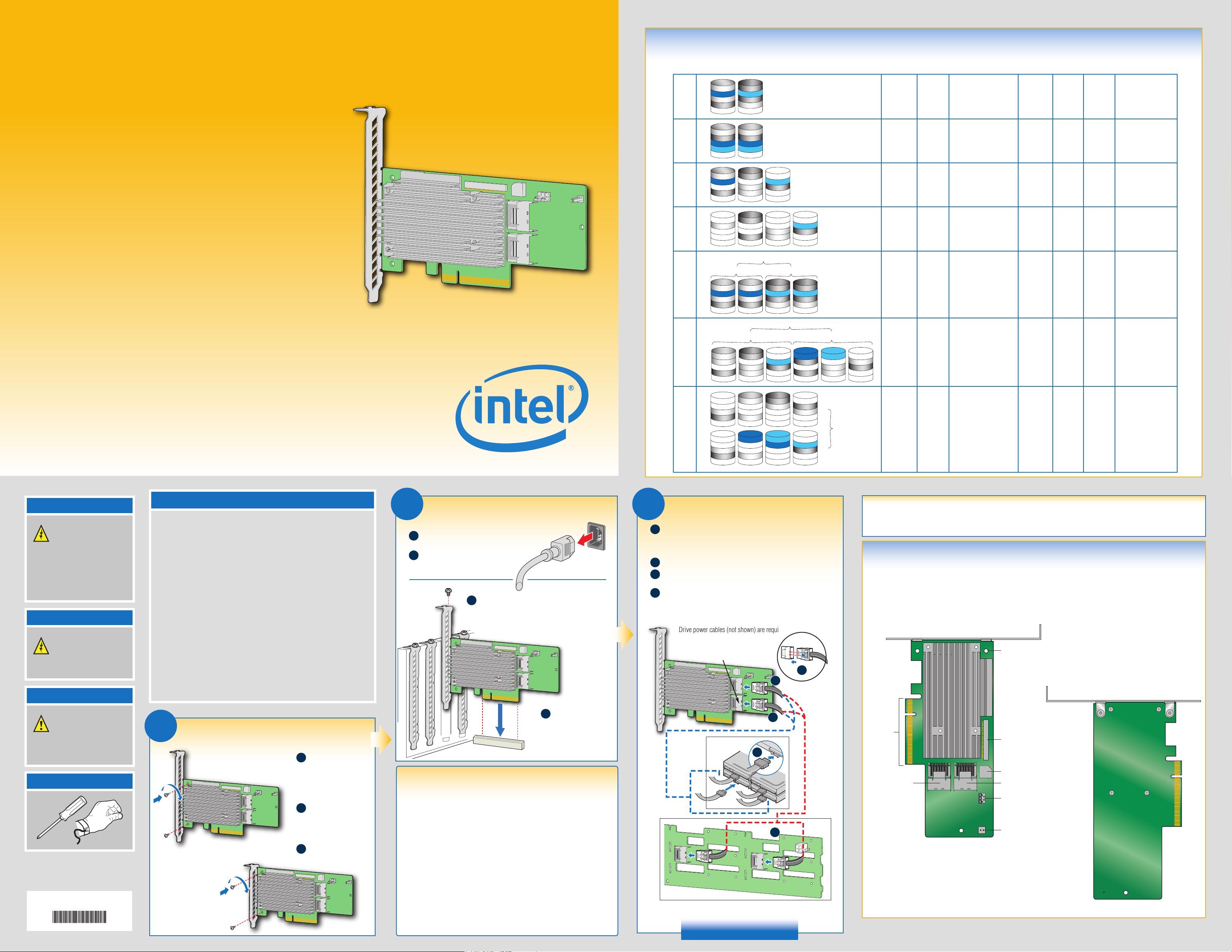
Choosing the Right RAID Level
RAID
Minimum
Physical
Drives
Fail PDs
Allowed
Method Capacity
Read
Speed
Write
Speed
Good Usage
RMS25PB080, RMS25PB040, RMT3PB080,
and RMS25PB080N
Quick Start User's Guide
This guide contains step-by-step instructions for installing
the Intel® Integrated RAID Module RMS25PB080, RMS25PB040,
RMT3PB080, and RMS25PB080N and information on
using the BIOS setup utility to configure a single logical
drive array and install the driver into the operating system.
For more advanced RAID configurations, or to install with other
operating systems, please refer to the Hardware User’s Guide.
These guides and other supporting documents
(including a list of supported server boards) are also located on the web at:
http://www.intel.com.
If you are not familiar with ESD (Electrostatic Discharge) procedures used
during system integration, see your Hardware Guide for complete ESD
®
procedures. For more details on Intel
RAID controllers, see:
www.intel.com/go/serverbuilder.
Read all cautions and warnings first before starting your RAID Controller
integration.
Intel® Integrated RAID Module RMS25PB080 as shown
*
10
50
D1
D3
0
1
5
6
D4
D5
D7
D
i
D1
D2
D4
D3
D4
D
i
D1
D3
D4
P
D7
D
i
D1
D3
D4
P1
P2
D
i
D2
D4
D4
D6
D8
1
k
s
1
k
s
1
k
s
1
k
s
2
k
D
s
i
D1
D2
D4
D3
D4
2
k
D
s
i
D2
P
D4
D5
D8
D
s
i
D2
P1
D4
P2
D7
D
s
i
P
D4
D4
D6
P
2
k
2
k
3
k
D
s
i
P1
P2
D4
D5
D8
D
i
P2
D4
D4
D6
P1
3
k
s
4
k
D
s
i
2 NONE Striping (speed) 100% Excellent Excellent High throughput
workstation
2
3 1 Striping and
1 Mirroring
(redundancy)
distributed parity
50% Very
n-1
(67-94%)
good
Very
good
Good OS, apps
entry level
Good Data, web/media
server
(fault tolerance)
3 2 Striping with dual
distributed parity
n-2
(50-88%)
Good Good High fault
tolerance
R0
R1 R1
D1
D3
D4
D5
D7
D
i
D1
D3
D4
D5
D7
1
k
D
s
i
D2
D4
D4
D6
D8
2
k
D
s
i
D2
D4
D4
D6
D8
3
k
s
4
k
D
s
i
4 1 per
mirror set
Striping across
mirrors
50% Very
good
Good
Database, file,
mail servers
R0
R5
D4
P
D4
D11
D16
4
k
s
i
D
s
i
P
D8
D4
D12
P
5
k
6
k
D
s
i
set
6 1 per R5
Striping across R5
arrays
n-2
(67-94%)
Excellent Very
Good
Database, file,
mail servers
D1
D5
D4
D13
D
R5
D2
P
P
s
i
D4
D5
D14
1
k
D
s
i
P
D6
D4
D10
P
D
2
s
i
k
D3
D7
D4
P
D15
3
k
D
Warning
Read all caution and safety
statements in this document
before performing any of the
instructions. Also see the Intel®
Server Board and Server Chassis
Safety Information document at:
http://www.intel.com/support/
motherboards/server/sb/cs-010770.
htm for complete safety information.
Warning
Installation and service of
this product should only be
performed by qualified service
personnel to avoid risk of injury from
electrical shock or energy hazard.
What you will need to begin
• SAS 2.0 or SATA III hard disk drives (backward compatible to support
SAS 1.0 or SATA II hard disk drives) for Intel
RMS25PB040, and RMS25PB080N
SATA III hard disk drives (backward compatible to support SATA II hard disk drives)
®
for Intel
Integrated RAID Module RMT3PB080
®
• Intel
Integrated RAID Module RMS25PB080, RMS25PB040, RMT3PB080, or
RMS25PB080N (SAS/SATA cables need to be prepared separately)
• SAS/SATA cable accessory kit, which can be ordered from Intel
Please see the Tested Operating System List for available cable accessory kits at:
http://www.intel.com/p/en_US/support/server
• Server board with a x8 or x16 PCI Express* slot (this controller is designed to meet
the x8 PCI Express* Generation 3 specification and is backward compatible with
generation 2 or 1 slots)
• Resource CD, which is shipped with systems or boards
• Operating system installation media: Microsoft Windows Server 2003*,
Microsoft Windows Server 2008*, Microsoft Windows Server 2012*,
Microsoft Windows 7*, Microsoft Windows Vista*, Red Hat* Enterprise Linux,
SUSE* Linux Enterprise Server, VMware* ESX Server 4, and VMware* ESXi 5.
®
Integrated RAID Module RMS25PB080,
®
separately.
2
Install the RAID Module
Power down the system and disconnect the
A
power cord.
Remove the system cover and any
B
other pieces to access the
PCI Express* slot.
Firmly press the RAID module into an available x8 or
C
x16 PCI Express* Slot. Secure the RAID module
bracket to the system back panel.
The Intel
shown for illustrative purpose.
®
Integrated RAID Module RMS25PB080 is
P1
P2
D4
D9
D13
D
P1
P2
D4
D11
D15
D
i
i
60
3
Connect the RAID Module
Connect the wide end of the cable to the up silver connector (ports
A
0-3).
®
The Intel
Integrated RAID Module RMS25PB080 is shown for
D1
P1
D4
P2
D14
1
k
D
s
k
s
i
D3
P1
D4
P2
D16
5
D
i
D2
D5
D4
P1
P2
2
k
s
6
k
s
3
k
D
s
i
D4
D7
D4
P1
P2
7
k
D
s
i
illustrative purpose.
Push the cable into the silver connector until it makes a slight click.
B
If using more than four drives, connect the wide end of the second
C
cable to the down silver connector (ports 4-7).
Connect the other ends of the cables to SATA drives or to the ports
D
on a SATA or SAS backplane.
Notes: Both non-expander backplanes (one cable per drive) and
expander backplanes (one or two total cables) are supported.
Drive power cables (not shown) are required.
Ports 4-7
(This connector is not available on
®
Integrated RAID Module RMS25PB040 )
Intel
A
P2
D6
D4
R6
D10
P1
D
P2
D8
D4
D12
P1
D
4
k
s
i
R0
6 2 per R6
set
Striping across R6
arrays
n-4
(50-88%)
Very
good
Good Critical data
R6
8
k
s
i
Audible Alarm Information
For information about the audible alarm and how to silence or disable it, see the reverse side of this document.
Intel® Integrated RAID Module
RMS25PB080, RMS25PB040, RMT3PB080,
and RMS25PB080N Reference Diagram
Front View
Bracket Screw(2)
B
Back View
Caution
Observe normal ESD
[Electrostatic Discharge]
procedures during system
integration to avoid possible
damage to server board and/or
other components.
Tools Required
Phillips*
screwdriver
Intel is a registered trademark of Intel Corporation or its
subsidiaries in the United States and other countries.
*Other names and brands may be claimed as the property
of others. Copyright © 2014, Intel Corporation. All rights
reserved.
G42737-006
Anti-static
wrist strap
1
Full-height
Bracket
Install the Bracket
Low-profile
Bracket
Determine whether the
A
full-height bracket or
the low-profile bracket
will fit in the server’s
PCI back plate.
Line up the proper
B
bracket with the
board, making sure
the two holes align.
Install and tighten the
C
two screws.
D
PCI Express* Slot (3.3 V)
Building Value with Intel®
Server Products, Programs, and Support
Get the high-value server solutions you
need by taking advantage of the outstanding
value Intel
®
provides to system integrators:
• High-quality server building blocks
• Extensive breadth of server building blocks
• Solutions and tools to enable e-Business
• Worldwide 24x7 technical support
(AT&T Country Code +866-655-6565)
1
• World-class service, including a
three-year limited warranty and Advanced
Warranty Replacement
For more information on Intel
server offerings, visit the Intel
1
®
's added-value
®
ServerBuilder
website at: www.intel.com/go/serverbuilder.
®
Intel
ServerBuilder is your one-stop
shop for information about all of Intel
Server Building Blocks such as:
• Product information, including
product briefs and technical product
specifications
• Sales tools, such as videos and
presentations
• Training information, such as the
®
Intel
Online Learning Center
• Support Information and much more
1
Available only to Intel® Channel Program
Members, part of Intel
Secure the RAID module
bracket to the system
back panel.
®
e-Business Network.
C
x8 PCI
Express*
Interface
D
J4B1 Ports 4-7
(This connector is
not available on
®
Integrated
Intel
RAID Module
®
's
RMS25PB040)
D
Rear view of four SATA drives or backplane connected to ports
on the Intel
®
Integrated RAID Module RMS25PB080.
Go to Step 4 on Side 2
For more information on the jumpers referenced in this diagram, refer to user guide located on the web at:
http://www.intel.com/p/en_US/support/server/
J4A1 BBU/RMFBU
Connector
(This connector is
not available on
Intel® Integrated RAID Module
RMS25PB080N)
Speaker
J4A2 Ports 0-3
J5A2 Advanced Software
Hardware Key Connector
J6A2 HDD Activity
Connector
Page 2

4
Use the Intel® RAID BIOS Console Utility to create a RAID Volume
Note: As necessary, see “Choosing the Right RAID Level” on side 1 of this Quick Start
User's Guide for a brief description of the RAID levels.
Side 2
For this example, Manual Configuration is used. Click Next.
5
(For further information, see the Intel
Resource CD.)
Power on the system and press <Ctrl> + <G> when the following screen
1
is displayed.
®
RAID Software User’s Guide on the
When the Intel® RAID BIOS Console starts, it will display the
2
®
Intel
Integrated RAID Module RMS25PB080 installed in the system. Click on
the "Adapter No." radio button to choose the controller, and then click Start.
Add physical drives to the array by pressing the <Ctrl> key while clicking on
6
entries under Physical Drives. Once you have selected all the drives you
wish to add to the array, click Add To Array. Then, click Next.
After a brief pause, the RAID BIOS Console screen is displayed.
3
Click Configuration Wizard.
Define further arrays or click Accept DG if finished. Then, click Next.
7
Select New Configuration and click Next.
4
Select the RAID Level from the drop-down list. Select the Stripe Size.
8
Enter the size of the logical drive. Click Accept.
Click Next.
9
Click Yes.
10
Click Yes.
11
Select Fast Initialize to do a preliminary initialization of the drives
12
for loading the operating system. A full initialization will occur in
the background.
Creation of a RAID volume is now complete.
5
Install the Operating System Drivers
Note: Below section lists the general driver loading process for frequently used operating systems. For more details, and for other supported operating systems, refer to the
corresponding driver release notes to get latest information.
Microsoft
Windows 2003*
Create installation media (floppy disk required for Microsoft Windows 2003*; removable
1
media, such as a floppy disk, USB device, or CD/DVD-ROM, required for Microsoft
Windows 2008*). See the instructions at the right.
Boot the server and start the OS installation.
2
Press the <F6> key as soon as the first
3
screen appears.
4
When prompted to specify a mass
storage controller:
a. Press <S> to specify additional storage
devices.
b. Insert the installation driver disk that
you created in step 1 above.
c. Press the <Enter> key to select the
“Installation Driver” and continue with
the Windows* installation.
Follow the on-screen instructions to complete the Windows installation.
5
OR
Windows 2008*/2012*
When you see: “Where do you want to
install Windows?”, select Load Driver,
and then click Next.
When prompted by the Load Driver dialog:
a. Insert the removable installation media
that you created in step 1 above.
b. Press the <Enter> key to select the
“Installation Driver” and continue with
the Windows* installation.
Microsoft
Red Hat*
OR
1
2
3
4
5
Enterprise Linux
Create installation media (removable media, such as a floppy disk, USB device,
or CD/DVD-ROM, required). See the instructions at the right.
Boot the system with Red Hat*
Enterprise Linux CD-ROM.
At the boot prompt, insert the
Linux installation disk that you created
in step 1.
Type Linux dd, and press the
<Enter> key.
Follow the on-screen instructions to complete the installation. The RAID controller
driver is automatically detected and installed.
OR
SuSE* Linux
Enterprise Server
Boot the system with SuSE* Linux
Enterprise Server (SLES) CD-ROM.
When the first screen displays, insert the
Linux installation disk that you created
step 1.
Press the <F5> key for SLES 10 or the
<F6> key for SLES 11 to load the driver,
and then select an installation menu
option.
To manage a RAID array, install Intel®RAID Web Console 2
Install the Intel® RAID Web Console 2 package from the Resource CD.
Extract the contents of the ZIP file and run Setup.exe from the Disk1 folder.
Choose one of four installation modes: Complete (installs all features), Client (administrative machine only), Server (can be managed remotely), or StandAlone (only manages itself).
To start Intel
®
RAID Web Console 2 from within the OS: Choose Start | Programs | RAID WebConsole | RAID WebConsole 2. For additional details, see the Intel® RAID Software User’s Guide.
Install the Intel® RAID Web Console 2 package from the Resource CD.
Unpack Linux_rwc2_**tar.gz.
Remove any line breaks and allow permissions by typing
$> tr -d ‘\15\32’ < existing_file_name > new_file_name
$> chmod a+x new_file_name
Run ./install.sh
Maximum size of drive
located here
Create Installation Media
Obtain the drivers either from the resource CD or the Intel® website.
1
If using the Resource CD, insert the resource CD. Browse to \Drivers and then the matching OS folder.
2
OR
Go to http://downloadcenter.intel.com and locate your product under Server Products in the left menu.
Microsoft Windows* Linux*
Extract the files from the zip file to your
3
hard drive. Copy the appropriate files to a
floppy disk (for Microsoft Windows 2003*)
or removable media (for Microsoft
Windows 2008*).
Copy the matching .sys, .cat,
.oem, and .inf driver files to a floppy disk
or removable media.
Extract the driver update disk (DUD) image (file
extension .img) from the zip file to your hard drive.
If you have a system with Microsoft Windows*, you
will need a third-party utlity such as ‘rawrite’ to
extract the DUD image to a floppy disk. For a system
under Linux* or Sun Solaris*, use the ‘dd’ command
as follows:
dd if=<image_file_name> of=<path-to-media>
‘path-to-media’ is usually /dev/fd0, but may
differ if you are using a USB floppy drive.
Understanding the Audible Alarm
The audible alarm will beep under two conditions: When a drive has failed, and during and following a rebuild.
The drive failure alarms are as follows:
■
Degraded Array: Short tone, one second on, one second off
■
Failed Array: Long tone, three seconds on, one second off
■
Hot Spare Commissioned: Short tone, one second on, three seconds off
The drive failure tones will repeat until the problem is corrected or until the alarm is silenced or disabled.
The rebuild alarm tone remains ON during the rebuild. After the rebuid completes, an alarm with a different tone
will sound, signaling the completion of the rebuild. This is a one-time (non-repeating) tone.
The alarm can be disabled either in the Intel
utilities. When disabled, the alarm will not sound unless it is re-enabled in one of the utilities.
The alarm can be temporarily silenced either in the Intel
management utilities. The alarm is not disabled and will sound again if another event occurs. The temporarily
silenced alarm will be enabled if the system is power cycled.
®
BIOS Console or in the Intel® Web Console 2 management
®
BIOS Console or in the Intel
®
Web Console 2
 Loading...