

Page 1

Intel® RAID High Availability Storage
User Guide
Order Number: G85745-001
Page 2

Disclaimer
INFORMATION IN THIS DOCUMENT IS PROVIDED IN CONNECTION WITH INTEL® PRODUCTS. NO
LICENSE, EXPRESS OR IMPLIED, BY ESTOPPEL OR OTHERWISE, TO ANY INTELLECTUAL PROPERTY
RIGHTS IS GRANTED BY THIS DOCUMENT. EXCEPT AS PROVIDED IN INTEL®'S TERMS AND CONDITIONS
OF SALE FOR SUCH PRODUCTS, INTEL® ASSUMES NO LIABILITY WHATSOEVER AND INTEL®
DISCLAIMS ANY EXPRESS OR IMPLIED WARRANTY, RELATING TO SALE AND/OR USE OF INTEL®
PRODUCTS INCLUDING LIABILITY OR WARRANTIES RELATING TO FITNESS FOR A PARTICULAR
PURPOSE, MERCHANTABILITY, OR INFRINGEMENT OF ANY PATENT, COPYRIGHT OR OTHER
INTELLECTUAL PROPERTY RIGHT.
A "Mission Critical Application" is any application in which failure of the Intel® Product could result, directly or
indirectly, in personal injury or death. SHOULD YOU PURCHASE OR USE INTEL®'S PRODUCTS FOR ANY SUCH
MISSION CRITICAL APPLICATION, YOU SHALL INDEMNIFY AND HOLD INTEL® AND ITS SUBSIDIARIES,
SUBCONTRACTORS AND AFFILIATES, AND THE DIRECTORS, OFFICERS, AND EMPLOYEES OF EACH,
HARMLESS AGAINST ALL CLAIMS COSTS, DAMAGES, AND EXPENSES AND REASONABLE ATTORNEYS'
FEES ARISING OUT OF, DIRECTLY OR INDIRECTLY, ANY CLAIM OF PRODUCT LIABILITY, PERSONAL
INJURY, OR DEATH ARISING IN ANY WAY OUT OF SUCH MISSION CRITICAL APPLICATION, WHETHER
OR NOT INTEL® OR ITS SUBCONTRACTOR WAS NEGLIGENT IN THE DESIGN, MANUFACTURE, OR
WARNING OF THE INTEL® PRODUCT OR ANY OF ITS PARTS.
Intel® may make changes to specifications and product descriptions at any time, without notice. Designers must not rely
on the absence or characteristics of any features or instructions marked "reserved" or "undefined". Intel® reserves these
for future definition and shall have no responsibility whatsoever for conflicts or incompatibilities arising from future
changes to them. The information here is subject to change without notice. Do not finalize a design with this information.
The products described in this document may contain design defects or errors known as errata which may cause the
product to deviate from published specifications. Current characterized errata are available on request.
Contact your local Intel® sales office or your distributor to obtain the latest specifications and before placing your product
order.
Copies of documents which have an order number and are referenced in this document, or other Intel® literature, may be
obtained by calling 1-800-548-4725, or go to: http://www.intel.com/design/literature.
ii Intel® RAID High Availability Storage User Guide
Page 3

Important Safety Instructions
Important Safety Instructions
Read all caution and safety statements in this document before performing any of the instructions.
See Intel® Server Boards and Server Chassis Safety Information at
http://support.intel.com/support/motherboards/server/sb/cs-010770.htm.
Wichtige Sicherheitshinweise
Lesen Sie zunächst sämtliche Warn- und Sicherheitshinweise in diesem Dokument, bevor Sie eine
der Anweisungen ausführen. Beachten Sie hierzu auch die Sicherheitshinweise zu Intel®Serverplatinen und -Servergehäusen unter
http://support.intel.com/support/motherboards/server/sb/cs-010770.htm.
重要安全指导
在执行任何指令之前,请阅读本文档中的所有注意事项及安全声明。 和/或
http://support.intel.com/support/motherboards/server/sb/cs-010770.htm 上的 Intel® Server Boards
and Server Chassis Safety Information(《Intel 服务器主板与服务器机箱安全信息》)。
Important Safety InstructionsConsignes de sécurité
Lisez attention toutes les consignes de sécurité et les mises en garde indiquées dans ce document
avant de suivre toute instruction. Consultez Intel® Server Boards and Server Chassis Safety
Information rendez-vous sur le site http://support.intel.com/support/motherboards/server/sb/cs-
010770.htm.
Instrucciones de seguridad importantes
Lea todas las declaraciones de seguridad y precaución de este documento antes de realizar
cualquiera de las instrucciones. Vea Intel® Server Boards and Server Chassis Safety Information
en http://support.intel.com/support/motherboards/server/sb/cs-010770.htm.
Intel® RAID High Availability Storage User Guide iii
Page 4

WARNINGS
Server power on/off: The push-button on/off power switch on the
front panel of the server does not turn off the AC power. To remove
AC power from the server, you must unplug the AC power cord from
either the power supply or wall outlet.
Hazardous conditions—power supply: Hazardous voltage, current,
and energy levels are present inside the power supply enclosure.
There are no user-serviceable parts inside it; servicing should only be
done by technically qualified personnel.
Hazardous conditions—devices and cables: Hazardous electrical
conditions may be present on power, telephone, and communication
cables. Turn off the server and disconnect telecommunications
systems, networks, modems, and the power cord attached to the
server before opening it. Otherwise, personal injury or equipment
damage can happen.
iv Intel® RAID High Availability Storage User Guide
Page 5

Table of Contents
1. Introduction .................................................................................................................. 6
Concepts of High-Availability DAS ................................................................................ 6
Intel® RAID High Availability Storage Terminology ..................................................... 7
Intel® RAID High Availability Storage Solution Features ............................................... 7
2. Hardware and Software Setup ...................................................................................... 9
Installing Intel® RAID Premium Feature Key AXXRPFKHA2 ........................................ 9
Installing Intel® RAID High Availability Storage Hardware ........................................... 10
Setting Up a Cluster-in-a-Box Configuration ................................................. 11
Setting Up a Two-Server Configuration with External JBOD Configuration... 13
Cabling Configurations ............................................................................................... 16
Installing Intel® RAID High Availability Storage Software ............................................ 20
Installing the Operating System and the Failover Clustering Feature ........... 20
Installing the Intel RAID Driver ..................................................................... 21
Installing the Management Tools .................................................................. 21
3. Creating the Intel® RAID High Availability Storage Configuration ................................ 22
Validating the Failover Configuration .......................................................................... 22
Creating the Cluster .................................................................................................... 22
Creating Virtual Drives on the Controller Nodes .......................................................... 24
Creating Shared VDs with the Intel® RAID BIOS Console ........................... 24
Creating Shared VDs with CmdTool264.exe on Windows Server 2012 ........ 28
Creating Shared VDs with RWC2 ................................................................. 34
Intel® RAID High Availability Storage SSD Cache Support....................................... 37
4. System Administration ................................................................................................ 42
High Availability Properties ......................................................................................... 42
Understanding Failover Operations ............................................................................ 43
Understanding and Using Planned Failover ................................................. 45
Understanding Unplanned Failover .............................................................. 47
Updating the Intel® RAID High Availability Storage Controller Firmware ..................... 47
Updating the Intel RAID Driver .................................................................................... 48
Updating the Driver in Windows Server 2008 R2 .......................................... 48
Updating the Driver in Windows Server 2012 ............................................... 50
Performing Preventative Measures on Disk Drives and VDs....................................... 52
Troubleshooting .................................................................................................................. 53
Reference Checklist of Required Intel® RAID High Availability Storage Components 53
Verifying Intel® RAID High Availability Storage Support in Tools and the OS Driver . 53
Confirming SAS Connections ..................................................................................... 55
Using Intel® RAID BIOS Console to View Connections for Controllers,
Expanders, and Drives ................................................................ 55
Using Intel® RAID BIOS Console to Verify Dual-Ported SAS Addresses to
Disk Drives ................................................................................. 55
Using CmdTool2 to Verify Dual-Ported SAS Addresses to Disk Drives ........ 57
Using RWC2 to Verify Dual-Ported SAS Addresses to Disk Drives .............. 58
Understanding SSD Cache Behavior During a Failover .............................................. 59
Error Situations and Solutions .................................................................................... 59
Intel® RAID High Availability Storage User Guide v
Page 6

1. Introduction
This document explains how to set up and configure the hardware and software for the Intel
RAID High Availability Storage solution.
The Intel® RAID High Availability Storage solution provides fault tolerance capabilities as a key
part of a high-availability data storage system. The RAID High Availability Storage solution
combines redundant Intel® RAID controllers, computer nodes, cable connections, SAS
expanders, and dual-port SAS drives to provide failover redundancy through multiple paths to
data.
The redundant components and software technologies provide a high-availability system with
ongoing service that is not interrupted by the following events:
A node failure which does not interrupt service because the configuration has multiple
nodes with cluster failover.
An expander failure which does not interrupt service because the dual expanders in every
enclosure provide redundant data paths.
A drive failure which does not interrupt service because RAID fault tolerance is part of the
configuration.
A system storage expansion or maintenance activity that can be completed without
requiring an interruption of service because of redundant components, management
software, and maintenance procedures.
®
Concepts of High-Availability DAS
In terms of data storage and processing, High Availability (HA) means a computer system
design that ensures a high level of operational continuity and data access reliability over a given
period of time. DAS means Directly Attached Storage. High-availability systems are critical to
the success and business needs of small and medium-sized businesses such as retail and
health care offices. An Intel® RAID High Availability Storage solution enables a customer to
maintain all elements of the high-availability system, with shared direct-attached drives
accessible to multiple servers through the use of failover clustering technology.
Simply defined, a cluster is a group of computers working together to run a common set of
applications and to present a single logical system to the client and application. Failover
clustering provides redundancy to the cluster group to maximize solution up-time by utilizing
fault-tolerant components. In the example of two servers with shared storage that comprise a
failover cluster, when a server fails, the failover cluster automatically moves control of the
shared resources to the surviving server with no interruption of access to data. This
configuration allows seamless failover capabilities in the event of planned failover (maintenance
mode) for maintenance or upgrade, or in the event of a failure of a system component such as a
failure of the CPU, memory, or other non-storage hardware.
SAS zoning is typically required to partition the storage domain between multiple initiators and
target devices. However, because multiple initiators can exist in a common shared storage
domain, there is a concept of device reservations in which physical drives, drive groups, and
Intel® RAID High Availability Storage User Guide 6
Page 7

virtual drives (VDs) are managed by a single initiator. In the case of Intel® RAID High
Availability Storage, I/O transactions and RAID management operations are processed by a
single Intel® RAID High Availability Storage controller, and the associated physical drives, drive
groups, and VDs are only visible to that controller. This key functionality allows the Intel® RAID
High Availability Storage solution to share VDs among multiple initiators as well as exclusively
constrain VD access to a particular initiator without the need for SAS zoning.
Node downtime in an HA system can be either planned or unplanned. Planned node downtime
is the result of management-initiated events, such as upgrades and maintenance. Unplanned
node downtime results from events that are not within the direct control of IT administrators,
such as failed software, drivers, or hardware. The Intel® RAID High Availability Storage solution
protects your data and system up-time from unplanned node downtime. It also enables you to
schedule node downtime to update hardware or firmware, and so on. When you bring one
controller node down for scheduled maintenance, the other node takes over with no interruption
of service.
Intel® RAID High Availability Storage Terminology
This section defines some additional important Intel® RAID High Availability Storage terms.
Cache Mirror: A cache coherency term describing the duplication of write-back cached data across
two controllers.
Exclusive Access: A host access policy in which a VD is only exposed to, and accessed by, a single
specified server.
Failover: The process in which the management of drive groups and VDs transitions from one
controller to the peer controller to maintain data access and availability.
HA Domain: A type of storage domain that consists of a set of HA controllers, cables, drive
enclosures, and storage media.
Peer Controller: A relative term to describe the HA controller in the HA domain that acts as the
failover controller.
Server/Controller Node: A processing entity composed of a single host processor unit or multiple
host processor units that is characterized by having a single instance of a host operating system.
Server Storage Cluster: An HA storage topology in which a common pool of storage devices is
shared by two computer nodes through dedicated Intel® RAID High Availability Storage controllers.
A host access policy in which a VD is exposed to, and can be accessed by, all servers
in the HA domain.
Intel® RAID High Availability Storage Solution Features
The Intel® RAID High Availability Storage solution supports the following HA features.
Server storage cluster topology
Dual-active HA with shared storage
Controller-to-controller intercommunication over SAS
Intel® High Availability Storage User Guide 7
Page 8

Write-back cache coherency
SSD Cache 1.0 (Read)
Shared and exclusive VD I/O access policies
Operating system boot from the controller (exclusive access)
Controller hardware and property mismatch detection, handling, and reporting
Global hot spare support for all volumes in the HA domain
Planned and unplanned failover modes
Clustering/HA services support:
Microsoft
®
failover clustering
Operating system support:
Microsoft Windows
®
Server 2008 R2
Microsoft Windows Server 2012
Full Intel RAID
®
features, with the following exceptions.
SATA drives do not support SCSI-3 persistent reservation and are not supported in Intel® RAID
High Availability Storage configurations.
SAS drives that do not support SCSI-3 persistent reservation are not supported in Intel® RAID
High Availability Storage configurations.
T10 Data Integrity Field (DIF) is not supported.
Self-encrypting drives (SED) and full disk encryption (FDE) are not supported.
SSD Cache 2.0 (write back) is not supported.
Dimmer switch is not supported.
SGPIO sideband signaling for enclosure management is not supported.
8 Intel
®
High Availability Storage User Guide
Page 9
2. Hardware and Software Setup
This chapter explains how to set up the hardware and software aspects of the Intel® RAID High
Availability Storage solution in a two-controller node with shared storage and fault-tolerant cabling for
one or more JBODs.
You can implement the Intel® RAID High Availability Storage solution with a two-server configuration
connected to a JBOD, or with a Cluster-in-a-Box (CiB) configuration in which all the server hardware
and disk drives are pre-connected inside a single enclosure. In both of these configurations, dual ported
backplanes are required in order to provide access for both server nodes to the disk drives. This chapter
explains how to set up both types of configurations.
Installing Intel® RAID Premium Feature Key AXXRPFKHA2
The Intel® RAID Premium Feature Key AXXRPFKHA2 is a hardware way to enable the High
Availability feature of the RAID controller. Following are the steps to install the Intel® RAID Premium
Feature Key.
1. Carefully remove the Intel® RAID Premium Feature Key from its packaging.
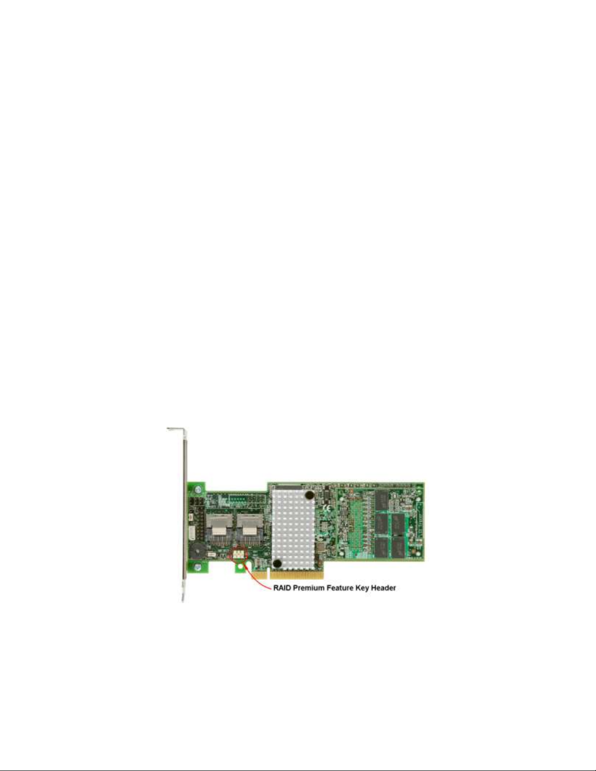
2. Locate the RAID Premium Feature Key connector on the Intel® RAID Controller. This is a 2-pin
shielded connector. The following figure shows the location of the RAID Premium Feature Key
connector on the Intel® RAID Controller RS25DB080. In the figure, the arrow points to the location of
the RAID Premium Feature Key connector. The location of RAID Premium Feature Key connector on
your Intel® RAID Controller may vary. Please refer to the User Guide for your Intel® RAID Controller
for the location of this connector.
Figure 1 Locating RAID Premium Feature Key connector on Intel® RAID Controller RS25DB080
3. With the 3-hole edge of the Intel® RAID Premium Feature key pointing to the RAID Premium Feature
Key 2-pin connector of the RAID controller, push the key onto the connector on the RAID controller.
Intel® High Availability Storage User Guide 9
Page 10
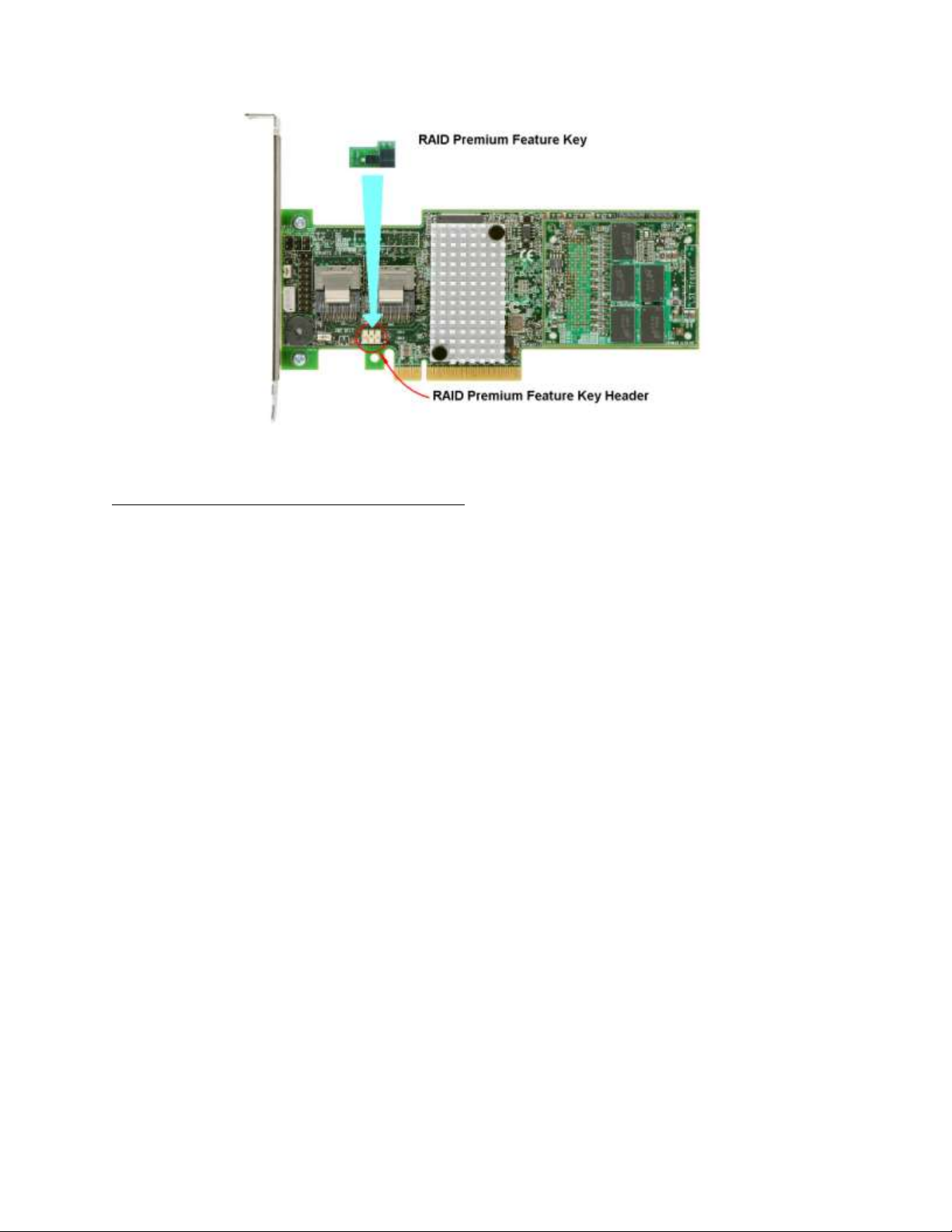
Figure 2 Installing RAID Premium Feature Key on Intel® RAID Controller RS25DB080
4. Refer to documentation of the Intel® RAID Controller from
http://www.intel.com/support/motherboards/server/ to finish installing the RAID controller into an Intel®
Server Board, or qualified third party server board.
Installing Intel® RAID High Availability Storage Hardware
The first step to setting up the Intel® RAID High Availability Storage solution is to install and configure
the hardware components. The following Intel® RAID High Availability Storage hardware checklist
outlines the baseline hardware components needed for a configuration with two controller nodes.
Two identical Intel
Two sets of external or internal (CiB) SAS cabling for each Intel
controller
One SAS drive backplane or external SAS JBOD with the following characteristics:
Support for 6Gb/s SAS
Dual ported backplanes or dual environmental services modules (ESMs)
Dual expanders connected to a shared-drive backplane that supports dual-ported drives
®
RAID High Availability Storage controller assemblies
®
RAID High Availability Storage
Support for SES
Support for dual-ported SAS and/or NL-SAS HDD and SSD drives
Support for SCSI-3 persistent reservation
Multiple 6Gb/s SAS or NL-SAS drives that support SCSI-3 persistent reservation
Note: The expanders and the dual-port backplane are programmed to route SAS data such that both
Intel® RAID High Availability Storage controllers can discover both SAS addresses for all of the drives.
For an Intel® RAID High Availability Storage configuration, the expander must have two four-lane In
ports. The expander also requires many disk ports assigned according to the cable and backplane
10 Intel
®
High Availability Storage User Guide
Page 11
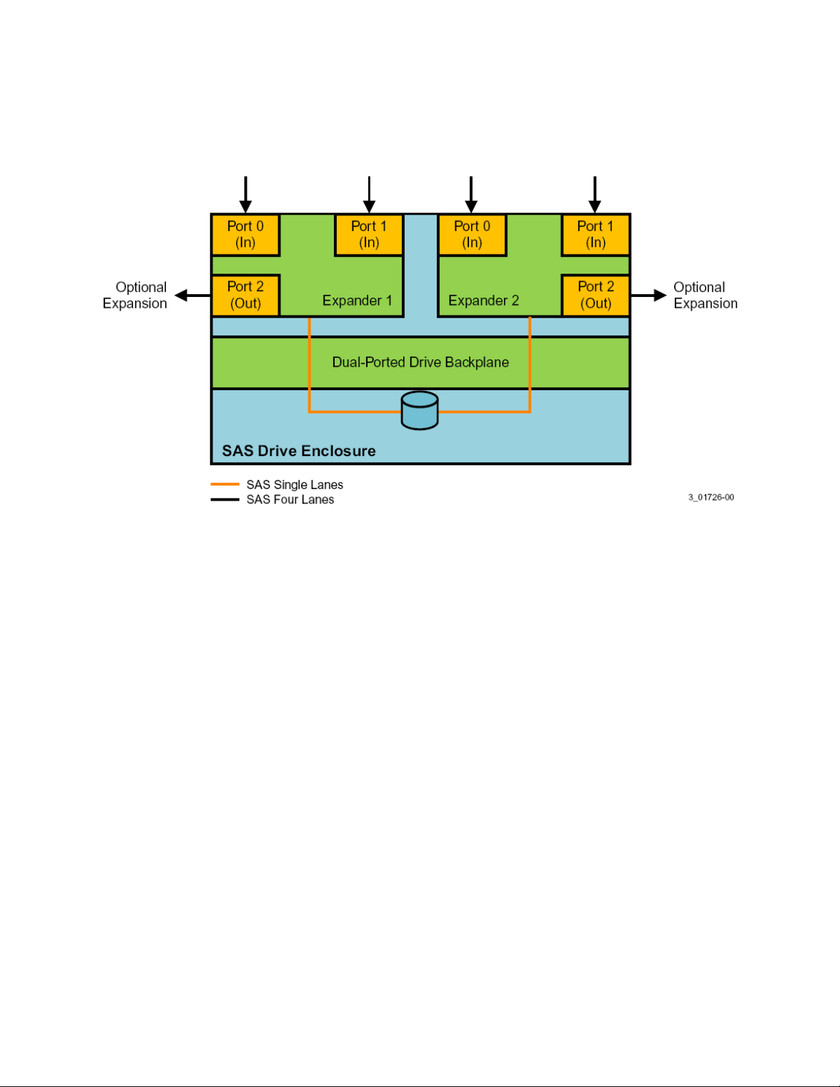
board connections. As an option, the expander is configured with a third four-lane port for cascaded
expanders, as shown in the following figure.
Figure 3 Intel® RAID High Availability Storage Expander Configuration
Note: Drive enclosures with dual ESM modules can support split modes or unified modes. For faulttolerant cabling configurations, you typically configure the enclosure in unified mode. (Check with
your drive enclosure vendor to determine the appropriate settings).
Setting Up a Cluster-in-a-Box Configuration
The CiB system design converges both server and storage by combining the processing power of multiple
servers with shared storage elements. A CiB system houses two servers and a common pool of direct
attached drives within one custom designed server enclosure. This server enclosure simplifies the setup
and deployment of two-node clusters because all necessary connections are preconfigured between the
servers and the drives, as shown in the following figure.
Intel® High Availability Storage User Guide 11
Page 12
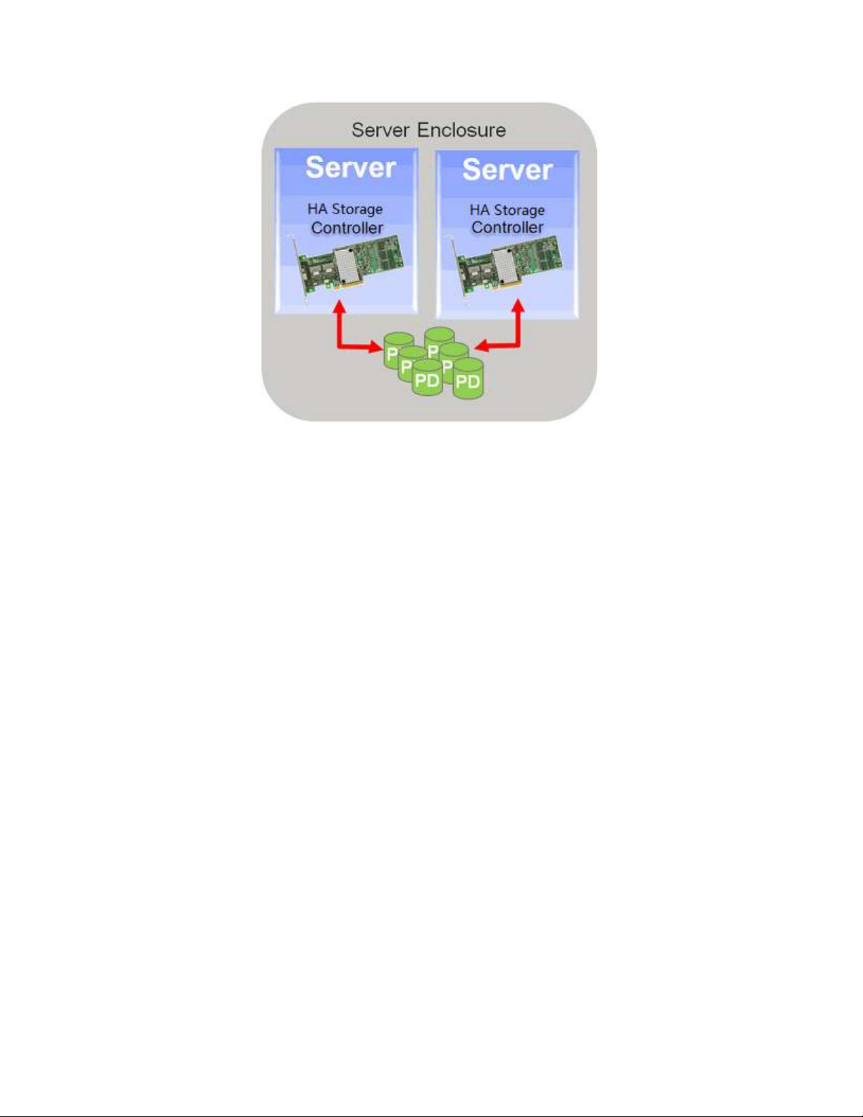
Figure 4 Intel® RAID High Availability Storage Cluster-in-a-Box Configuration
The cluster-in-a-box configuration for the Intel® RAID High Availability Storage solution requires a
specially designed server and storage chassis that includes two Intel® RAID High Availability Storage
controllers and multiple SAS disks. Because all components are inside the enclosure and are preconnected, the physical setup is minimal. Install the CiB enclosure in a standard rack and follow the
manufacturer’s instructions to complete the physical setup.
The following figure shows a diagram of a CiB Intel® RAID High Availability Storage configuration
connected to a network. The diagram includes the details of the SAS interconnections.
12 Intel
®
High Availability Storage User Guide
Page 13
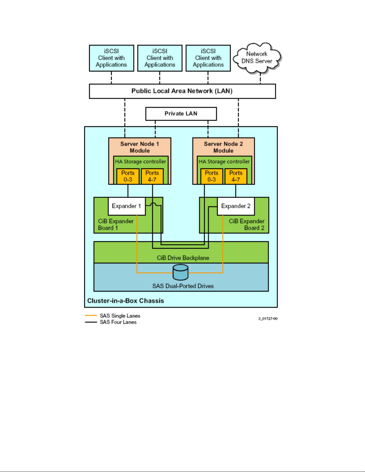
Figure 5 CiB Intel® RAID High Availability Storage Controller Configuration
Setting Up a Two-Server Configuration with External JBOD Configuration
The Intel® RAID High Availability Storage solution enables you to configure two separate, standard
servers with Intel® RAID High Availability Storage controllers that provide access to disks in the same
JBOD enclosure, or enclosures, for reliable, high-access redundancy, as shown in the following figure.
Intel® High Availability Storage User Guide 13
Page 14
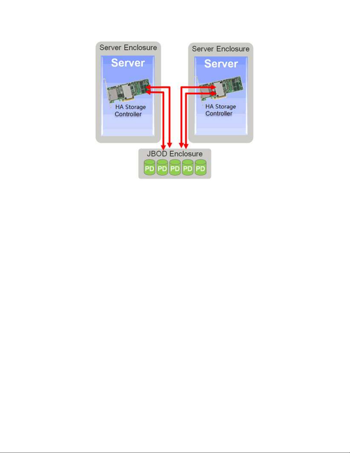
Figure 6 High-Availability Standard Server Configuration
This configuration enables you to use standard, readily available server hardware and disk enclosures to
set up a reliable Intel® RAID High Availability Storage configuration.
The dual-server-JBOD configuration for the Intel® RAID High Availability Storage solution requires the
following hardware for each of the two matched stand-alone server modules:
A Intel
®
RAID High Availability Storage controller board (RS25NB008, RS25SB008, etc). The
controller board firmware version must support clustering. You must use the same controller board
model in both servers.
Note: The Intel® RAID High Availability Storage solution is based on Intel RAID firmware that is
Intel® RAID High Availability Storage capable. Other versions of Intel RAID firmware do not provide
clustering support. When the second node boots, firmware version checks occur between the two
controllers, and the second node presents POST error messages if the Intel® RAID High Availability
Storage firmware versions do not match.
A monitor and mouse for each controller node.
Network cabling and SAS cabling to connect the servers and JBOD enclosures.
The following figure shows a diagram of a two-server Intel® RAID High Availability Storage
configuration connected to a network. The diagram includes the details of the SAS interconnections.
14 Intel
®
High Availability Storage User Guide
Page 15
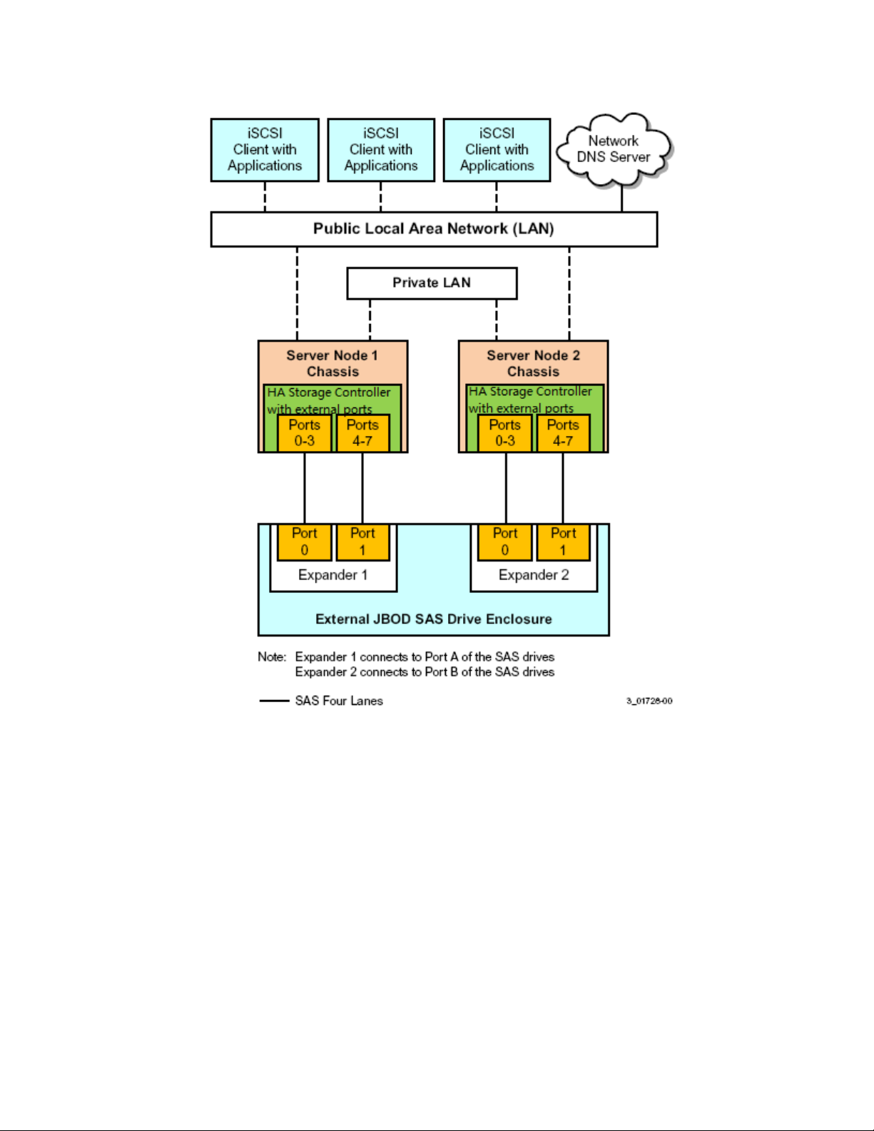
Figure 7 Two-Server Intel® RAID High Availability Storage Configuration
Follow these steps to set up the hardware for a dual-server-JBOD configuration for Intel® RAID High
Availability Storage clustering.
1. Install an Intel® RAID High Availability Storage controller board in each of the two server modules,
following the instructions in the Quick Installation Guide.
2. If necessary, install network boards in the two server modules and install the cabling between them.
3. Install the two server modules and the JBOD enclosure in an industry-standard cabinet, following the
instructions in the manufacturer documentation.
4. Connect the host SFF-8088 connectors on the JBOD enclosure, or enclosures, to the SFF-8088
connectors on the front of the two server modules.
See Section Cabling Configurations, for specific cabling instructions for one or two JBODs.
Intel® High Availability Storage User Guide 15
Page 16
5. Connect power cords to the server units and the JBOD enclosure and power the units.
Cabling Configurations
This section contains information about initially setting up a Intel® RAID High Availability Storage
configuration with one or two JBODs. It also explains how to add a second JBOD to a single-JBOD
configuration without interrupting service on the configuration.
The following figure shows how to set up a two-controller-node configuration with a single JBOD
enclosure.
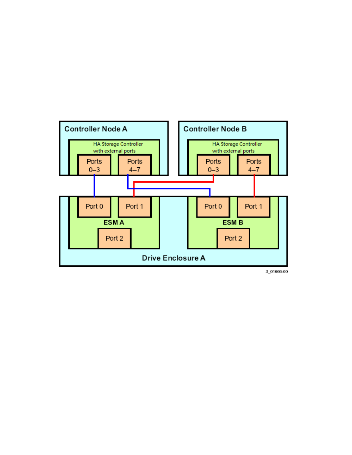
Figure 8 Two-Controller-Node Configuration with Single JBOD
The cross-connections between the controllers provide redundant paths that safeguard against ESM
failure.
To retain consistent device reporting, the corresponding port numbers for both controllers must be
connected to a common enclosure ESM. In this example, port 0 to port 3 of both controllers are connected
to ESM A and port 4 to port 7 of both controllers are connected to ESM B.
The following figure shows how to set up a two-controller-node configuration with two JBOD enclosures.
16 Intel
®
High Availability Storage User Guide
Page 17
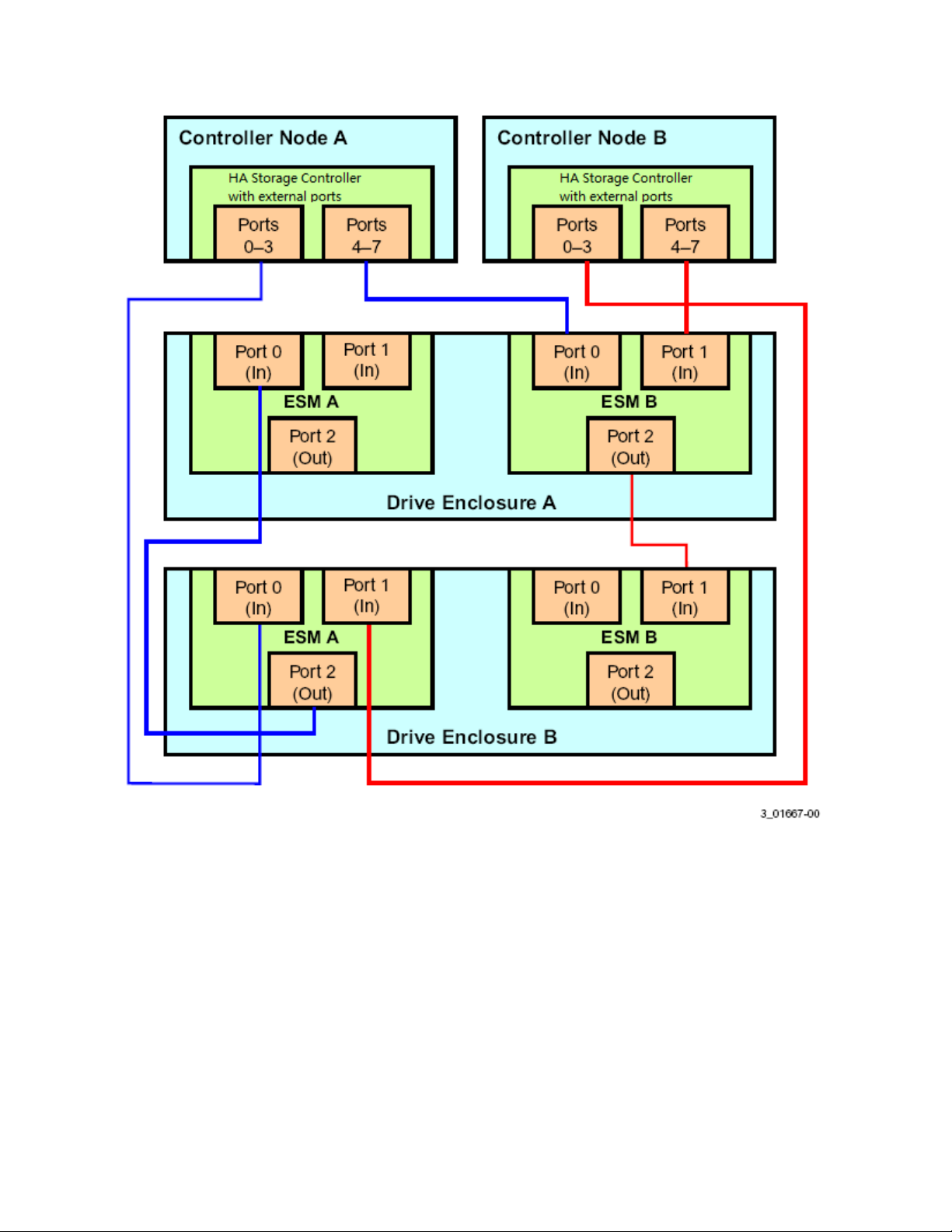
Figure 9 Two-Controller-Node Configuration with Dual JBODs
The top-down/ bottom-up cabling approach shown in this figure has the following benefits:
The cross-connections between controllers and ESMs safeguard against the complete disconnection
of a server from the drive enclosure.
Continued access to drives is assured in the event of a complete drive enclosure failure or removal.
Additional expansion drive enclosures can be hot-added without disrupting service, as shown in
Figure 9.
The following figure shows an incorrectly cabled configuration with two disk enclosures.
Intel® High Availability Storage User Guide 17
Page 18
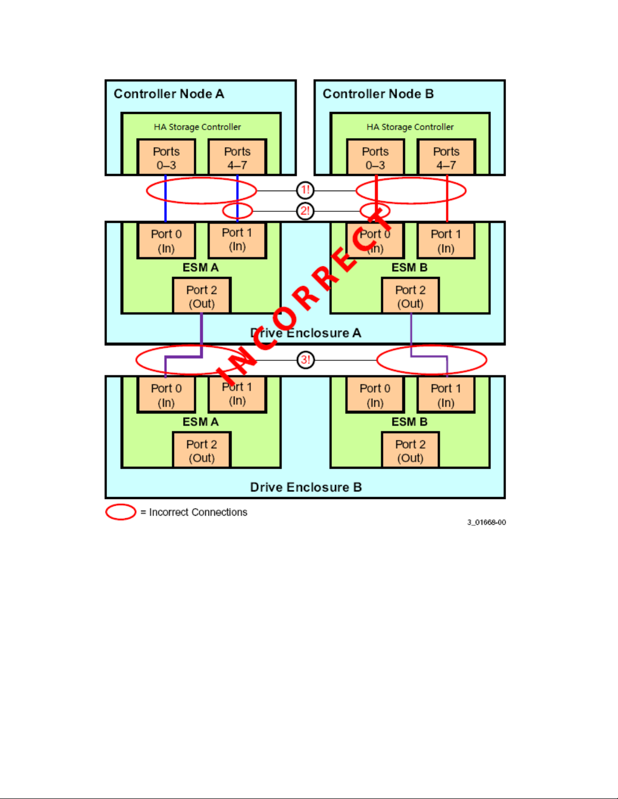
Figure 10 Example of Incorrect Cabling of Two Disk Enclosures
This configuration does not work for the following reasons (the numbers correspond to the labels in the
figure):
1. The failure of an ESM in drive enclosure A causes disconnection between a server and both drive
enclosures.
2. The lack of a proper connection from a controller port number to a common enclosure ESM results in
inconsistent device reporting.
3. The failure of drive enclosure A results in disconnection of drive enclosure B from both servers.
The following figure shows how to add a second disk enclosure to an existing two-server cluster without
interrupting service on the HA configuration.
18 Intel
®
High Availability Storage User Guide
Page 19
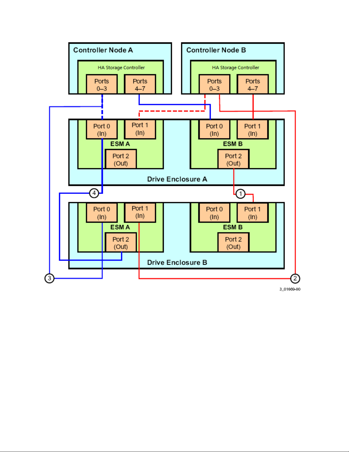
Figure 11 Adding a Second Disk Enclosure - Redundant Configuration
The steps for adding the second disk enclosure are as follows:
1. Connect a link from port 2 on ESM B of drive enclosure A to port 1 on ESM B of drive enclosure B.
2. Disconnect the link from port 1 on ESM A of drive enclosure A and reconnect it to port 1 on ESM A of
drive enclosure B.
3. Disconnect the link from port 0 on ESM A of drive enclosure A and reconnect it to port 0 on ESM A of
drive enclosure B.
4. Connect the link from port 2 on ESM A of drive enclosure B to port 0 on ESM A of drive enclosure A.
Intel® High Availability Storage User Guide 19
Page 20

Installing Intel® RAID High Availability Storage Software
The next step of setting up the Intel® RAID High Availability Storage solution is to install and configure
the software components. The following Intel® RAID High Availability Storage software checklist lists
the baseline software components needed for the two controller nodes.
One of the following supported Operating Systems:
Microsoft Windows Server 2008 R2
Microsoft Windows Server 2012
A version of the Intel RAID operating system driver that has support for the Intel
Availability Storage solution
A version of Intel
®
RAID Web Console 2 (RWC2) that has support for the Intel® RAID High
Availability Storage solution
A version of CmdTool2 that supports the Intel
(Optional) An SMI-S provider that supports the Intel
®
RAID High Availability Storage solution
®
RAID High Availability Storage solution
See Section - Verifying Intel® RAID High Availability Storage Support in Tools and the OS Driver, to
learn how to verify that you have the correct version of the tools and driver.
NOTE: Support for clustered RAID controllers is not enabled by default in the standard build of
Microsoft Windows Server 2008 R2. Consult with your server vendor to obtain a version of this
operating system that includes this support.
®
RAID High
Installing the Operating System and the Failover Clustering Feature
When you have finished physically configuring the Intel® RAID High Availability Storage hardware,
install one of the supported operating systems on both controller nodes, following the directions provided
by Microsoft.
You have two options for installing the operating system for each controller node:
Install it on a private volume connected to the system-native storage controller. The recommended
best practice is to install the operating system on this private volume because the disks in the
clustering configuration cannot see this volume. Therefore, no danger exists of accidentally
overwriting the operating system disk when you set up clustering.
Install it on an exclusive virtual drive connected to the Intel
controller. Exclusive host access is required for a boot volume so the volume is not overwritten
accidentally when you create virtual drives for data storage. For instructions on creating exclusive
virtual drives using the Intel® RAID BIOS Console, see Section - Creating Shared VDs with the
Intel® RAID BIOS Console.
NOTE: The Intel® RAID High Availability Storage solution does not support booting from a shared
operating system volume.
Install the Failover Cluster feature on both servers, following the instructions in the Microsoft
documentation.
®
RAID High Availability Storage
20 Intel
®
High Availability Storage User Guide
Page 21

Installing the Intel RAID Driver
The Intel® RAID High Availability Storage controllers use a driver that is also used by the Intel RAID
SAS products. Install the driver or update it to the version that supports the Intel® RAID High Availability
Storage controller. Refer to the installation steps in the release notes in the Intel RAID SAS Device
Driver package.
Installing the Management Tools
After you install the operating system on both controller nodes, install the RWC2 and CmdTool2
management tools or the SMI-S Provider by following the installations instructions contained in the Intel®
RAID Software User’s Guide.
Intel® High Availability Storage User Guide 21
Page 22

3. Creating the Intel® RAID High Availability Storage
Configuration
This chapter explains how to set up Intel® RAID High Availability Storage clustering on a Intel® RAID
High Availability Storage cluster-in-a-box configuration or a two-server configuration after the hardware
is fully configured and the operating system is installed.
Validating the Failover Configuration
Microsoft recommends that you validate the failover configuration before you set up failover clustering.
To do this, run the Validate a Configuration wizard for Windows Server 2008 R2 or Windows Server
2012, following the instructions from Microsoft. The tests in the validation wizard include simulations of
cluster actions. The tests fall into the following categories:
System Configuration tests. These tests analyze whether the two server modules meet specific
requirements, such as the requirement that the servers must run the same operating system version
and software updates.
Network tests. These tests analyze whether the planned cluster networks meet specific requirements,
such as requirements for network redundancy.
Storage tests. These tests analyze whether the storage meets specific requirements, such as whether
the storage correctly supports the necessary SCSI commands, and handles simulated cluster actions
correctly.
Follow these steps to run the Validate a Configuration wizard.
NOTE: You can also run the Validate a Configuration wizard after you create the cluster.
1. In the failover cluster snap-in, in the console tree, make sure Failover Cluster Management is selected
and then, under Management, click Validate a Configuration.
The Validate a Configuration wizard starts.
2. Follow the instructions for the wizard and run the tests.
Microsoft recommends that you run all available tests in the wizard.
3. When you arrive at the Summary page, click View Reports to view the results of the tests.
4. If any of the validation tests fails or results in a warning, correct the problems that were uncovered and
run the test again.
Creating the Cluster
The Microsoft Server 2012 operating system installation does not enable the clustering feature by default.
Follow these steps to view the system settings, and, if necessary, enable clustering in Microsoft Server
2012.
1. From the desktop, launch Server Manager.
2. Click Manage and select Add Roles and Features.
22 Intel
®
High Availability Storage User Guide
Page 23
3. If the Introduction box is enabled (and appears), click Next.
4. In the Select Installation Type box, select Role Based or Feature Based.
5. In the Select Destination Server box, select the system and click Next.
6. In the Select Server Roles list, click Next to present the Features list.
7. Make sure that failover clustering is installed, including the tools. If necessary, run the Add Roles and
Features wizard to install the features dynamically from this user interface.
8. If the cluster nodes need to support I/O as iSCSI targets, expand File and Storage Services, File
Services and check for iSCSI Target Server and Server for NFS.
The Server Manager includes a configuration validator under Server Manager> Tools> Failover Cluster
Manager…Validate a Configuration. Refer to the Microsoft documentation for more detailed information.
During creation of the cluster, Windows automatically defines and creates the quorum, a configuration
database that contains metadata required for the operation of the cluster. To create a shared VD for the
quorum, see the instructions in Section Creating Virtual Drives on the Controller Nodes.
NOTE: The recommended best practice is to create a small redundant VD for the quorum. A size of
500 MB is adequate for this purpose.
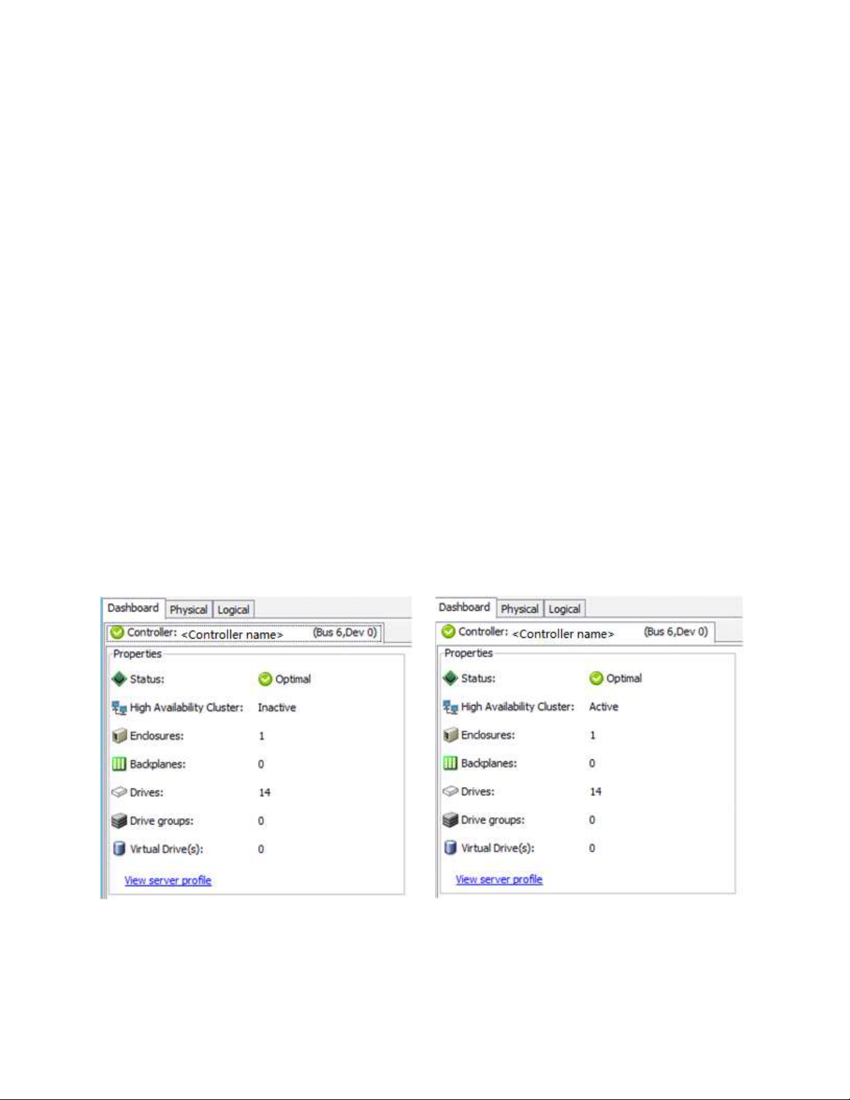
To determine if the cluster is active, run RWC2 and look at the Dashboard tab for the controller. The
first of two nodes that boots shows the cluster status as Inactive until the second node is running and the
RWC2 dashboard on the first node has been refreshed.
NOTE: To refresh the RWC2 dashboard, press F5 or select Manage > Refresh on the menu.
The following figure shows, on the left, the controller dashboard with Inactive cluster status. The
dashboard on the right side of the figure shows the change to Active cluster status.
Figure 12 Controller Dashboard: Inactive and Active Cluster Status
Intel® High Availability Storage User Guide 23
Page 24

Creating Virtual Drives on the Controller Nodes
The next step is creating VDs on the JBOD disks or on the disks in the cluster-in-a-box enclosure.
The Intel® RAID High Availability Storage cluster configuration requires a minimum of one shared VD
to be utilized as a quorum disk to enable Microsoft operating system support for clusters. Refer to the
Intel® RAID Software User’s Guide for information about the available RAID levels and the advantages
of each one.
As explained in the instructions in the following sections, VDs created for storage in an Intel® RAID
High Availability Storage configuration must be shared. If you do not designate them as shared, the VDs
are visible only from the controller node on which they were created.
You can use the Intel® RAID BIOS Console pre-boot utility to create the VDs. You can also use the
Intel® RAID Web Console 2 (RWC2) utility or the CmdTool2 utility to create VDs after Windows has
booted. Refer to the Intel® RAID Software User’s Guide for complete instructions on using these utilities.
Creating Shared VDs with the Intel® RAID BIOS Console
To coordinate the configuration of the two controller nodes, both nodes must be booted into the Intel®
RAID BIOS Console pre-boot utility. The two nodes in the cluster system boot simultaneously after
power on, so you must rapidly access both consoles. One of the systems is used to create the VDs; the
other system simply remains in the pre-boot utility. This approach keeps the second system in a state that
does not fail over while the VDs are being created on the first system.
NOTE: The Intel® RAID BIOS Console cannot see boot sectors on the disks. Therefore, be careful not
to select the boot disk for a VD. Preferably, unshare the boot disk before doing any configuration with
the pre-boot utility. To do this, select Logical Drive Properties and deselect the Shared Virtual Disk
property.
Follow these steps to create VDs with the Intel® RAID BIOS Console.
1. When prompted during the POST on the two systems, use the keyboard to access the Intel® RAID
BIOS Console pre-boot BIOS utility (on both systems) by pressing Ctrl-G.
You must respond quickly, because the system boot times are very similar and the time-out period is short.
When both controller nodes are running the Intel® RAID BIOS Console, follow these steps to create
RAID 5 arrays.
NOTE: To create a RAID 0, RAID 1, or RAID 6 array, modify the instructions to select the appropriate
number of disks.
2. Click Start.
3. On the Intel® RAID BIOS Console main page, click Configuration Wizard, as shown in the
following figure.
24 Intel
®
High Availability Storage User Guide
Page 25

Figure 13 Intel® RAID BIOS Console Main Page
The first Configuration Wizard window appears.
4. Select Add Configuration and click Next.
5. On the next wizard screen, select Manual Configuration and click Next.
The Drive Group Definition window appears.
6. In the Drives panel on the left, select the first drive, then hold down the Ctrl key and select more drives
for the array, as shown in the following figure.
Intel® High Availability Storage User Guide 25
Page 26

Figure 14 Selecting Drives
7. Click Add To Array, click ACCEPT, and click Next.
8. On the next screen, click Add to SPAN, then click Next.
9. On the next screen, click Update Size.
10. Select the Share Virtual Drive option on the bottom left of the window, as shown in the following
figure.
26 Intel
®
High Availability Storage User Guide
Page 27

Figure 15 Virtual Drive Definition
This option enables a shared VD that both controller nodes can access. If you uncheck this box, the VD
has a status of exclusive, and host access exists only for the controller node that created this VD.
11. On this same page, click Accept, then click Next.
12. On the next page, click Next.
13. Click Yes to accept the configuration.
14. Repeat the previous steps to create the other VDs.
As the VDs are configured on the first controller node, the other controller node’s drive listing is updated
to reflect the use of the drives.
15. When prompted, click Yes to save the configuration, and click Yes to confirm that you want to
initialize it.
16. Define hot spare disks for the VDs to maximize the level of data protection.
NOTE: The Intel® RAID High Availability Storage solution supports global hot spares and dedicated
hot spares. Global hot spares are global for the cluster, not for a controller.
17. When all VDs are configured, reboot both systems as a cluster.
Intel® High Availability Storage User Guide 27
Page 28

Creating Shared VDs with CmdTool264.exe on Windows Server 2012
CmdTool2 is a command-line-driven utility used to create and manage VDs. CmdTool2 can run in any
directory on the server. The following procedure assumes that a current copy of the 64-bit Windows
version of CmdTool2 is located on the server in c:\intel\cli.
The steps for creating a VD are slightly different depending on whether you run CmdTool2 in Windows
PowerShell® or from a Windows command prompt. Therefore, two sets of instructions are included.
Creating Shared VDs: Running CmdTool2 in Windows PowerShell
Follow these steps to create a shared VD with CmdTool2 on Microsoft Windows Server 2012 running in
Windows PowerShell.
NOTE: Enter the command line entries exactly as shown in the following instructions, because it is
slightly different than the syntax used for the Windows command prompt. The CmdTool2 help and
documentation do not include syntactical references to PowerShell.
1. On the Microsoft Server 2012 desktop, right-click the PowerShell icon and select Run as
Administrator from the pop-up menu, as shown in the following figure.
Figure 16 Starting PowerShell
2. At the PowerShell prompt, enter the command cd \intel\cli to change to the CmdTool2 directory.
3. At the PowerShell prompt, run the following command:
.\CmdTool264 "–cfgdsply –a0"
The -a0 parameter presumes that there is only one Intel® RAID High Availability Storage controller
in the system or that these steps reference the first Intel® RAID High Availability Storage controller
in a system with multiple controllers. The following figure shows some sample configuration
information that appears in response to the command.
28 Intel
®
High Availability Storage User Guide
Page 29

Figure 17 Sample Configuration Information
The command outputs many lines of information that scroll down in the PowerShell window. You
need to use some of this information in the command line to create the shared VD.
4. Find the drive enclosure number Device ID for the system and also the Device IDs of available
physical drives for the VD you will create.
In the preceding figure, the enclosure device ID of 20 appears close to the top of the window. Use the
scroll bar to find the device IDs of the physical drives for the VD. The format of the drive IDs appears
as follows:
Physical Disk: 1
Enclosure Device ID: 20
Slot Number: 2
Drive’s position: DiskGroup: 0, Span; 0, Arm: 1
Enclosure position: 0
Device Id: 1
WWN: 5000C5001AA6F4DC
5. Create the shared VD using the enclosure and disk device IDs with the following command line
syntax:
.\CmdTool264 "–cfgldadd –r5[20:1,20:2,20:3,20:4,20:5] WB RA direct –strpsz64 –a0"
The following notes explain the command line parameters.
The –cfgldadd parameter configures and adds a VD (logical disk).
The -r5 parameter selects RAID 5 as the RAID level.
Intel® High Availability Storage User Guide 29
Page 30

The opening and closing square brackets define the list of drives for the VD. Each drive is listed
in the form enclosure device ID: drive device ID.
The WB parameter sets the controller to use the write cache. (Alternatively, the WT parameter
sets the controller cache for write through.)
The RA parameter sets the controller cache for read ahead.
The direct parameter sets direct I/O.
The –strpsz64 parameter sets the stripe size to 64 KB.
The -a0 parameter selects the first Intel
®
RAID High Availability Storage controller in the system.
The Intel® RAID High Availability Storage version of CmdTool2 creates, by default, a shared
VD that is visible to all cluster nodes.
NOTE: To create a VD that is visible only to the node that created it (such as creating a boot
volume for this cluster node), add the -exclusive parameter to the command line.
The -a0 parameter selects the first Intel
®
RAID High Availability Storage controller in the system.
For more information about the CmdTool2 command line parameters, refer to the Intel® RAID
Controller Command Line Tool 2 User Guide
Creating Shared VDs: Running CmdTool2 from a Windows Command Prompt
Follow these steps to create shared VDs with CmdTool2 on Microsoft Windows Server 2012, running in
a Windows command prompt:
1. Move the mouse to the lower right hand corner of the screen and select Search when the icons appear,
as shown in the following figure.
Figure 18 Selecting Search
2. Search for cmd, as shown in the following figure.
30 Intel
®
High Availability Storage User Guide
Page 31

Figure 19 Searching for ‘cmd’
The system finds the command prompt.
3. Right-click the Command Prompt. A properties check indicator appears on the button, as shown in
the following figure.
Figure 20 Command prompt
The following button appears at the bottom of the desktop to open the command prompt as
Administrator.
Figure 21 Run as Administrator Button
Click the button to open a command prompt, as shown in the following figure.
Intel® High Availability Storage User Guide 31
Page 32

Figure 22 Windows Command Prompt
4. Enter the following command at the prompt:
CmdTool264 –cfgdsply –a0
The -a0 parameter presumes that there is only one Intel® RAID High Availability Storage controller
in the system or that these steps reference the first Intel® RAID High Availability Storage controller
in a system with multiple controllers. The following figure shows some sample configuration
information that appears in response to the command.
Figure 23 Sample Configuration Information
32 Intel
®
High Availability Storage User Guide
Page 33

The command outputs many lines of information that scroll down in the command prompt window.
You need to use some of this information in the command line to create the shared VD.
5. Find the drive enclosure number Device ID for the system and also the Device IDs of available
physical drives for the VD you will create.
In the preceding figure, the enclosure device ID of 20 appears close to the top of the window. Use the
scroll bar to find the device IDs of the physical drives for the VD. The format of the drive IDs appears
as follows:
Physical Disk: 1
Enclosure Device ID: 20
Slot Number: 2
Drive’ s position: DiskGroup: 0, Span; 0, Arm: 1
Enclosure position: 0
Device Id: 1
WWN: 5000C5001AA6F4DC
6. Create the shared VD using the enclosure and disk device IDs with the following command line
syntax:
CmdTool264 –cfgldadd –r5[20:1,20:2,20:3,20:4,20:5] WB RA direct –strpsz64 –a0
The following notes explain the command line parameters.
The –cfgldadd parameter configures and adds a VD (logical disk).
The -r5 parameter selects RAID 5 as the RAID level.
The opening and closing square brackets define the list of drives for the VD. Each drive is listed
in the form enclosure device ID: drive device ID.
The WB parameter sets the controller to use the write cache. (Alternatively, the WT parameter
sets the controller cache for write through.)
The RA parameter sets the controller cache for read ahead.
The direct parameter sets direct I/O.
The –strpsz64 parameter sets the stripe size to 64 KB.
The -a0 parameter selects the first Intel
®
RAID High Availability Storage controller in the system.
The Intel® RAID High Availability Storage version of CmdTool2 creates, by default, a shared
VD that is visible to all cluster nodes.
NOTE: To create a VD that is visible only to the node that created it (such as creating a boot
volume for this cluster node), add the -exclusive parameter to the command line.
The -a0 parameter selects the first Intel
®
RAID High Availability Storage controller in the system.
For more information about the CmdTool2 command line parameters, refer to the Intel® RAID
Controller Command Line Tool 2 User Guide
Intel® High Availability Storage User Guide 33
Page 34

Creating Shared VDs with RWC2
Follow these steps to create VDs for data storage with RWC2. When you create the VDs, you assign the
Share Virtual Drive property to them so they are visible from both controller nodes. This example
assumes you are creating a RAID 5 redundant VD. Modify the instructions as needed for other RAID
levels.
NOTE: Not all versions of RWC2 support Intel® RAID High Availability Storage. Check the release
notes to determine if your version of RWC2 supports Intel® RAID High Availability Storage. Also, see
Section - Verifying Intel® RAID High Availability Storage Support in Tools and the OS Driver.
1. In the left panel of the RWC2 Logical pane, right-click the Intel® RAID High Availability Storage
controller and select Create Virtual Drive from the pop-up menu.
The Create Virtual Drive wizard appears.
2. Select the Advanced option and click Next.
3. In the next wizard screen, select RAID 5 as the RAID level, and select unconfigured drives for the VD,
as shown in the following figure.
Figure 24 Drive Group Settings
4. Click Add to add the VD to the drive group.
The selected drives appear in the Drive groups window on the right.
5. Click Create Drive Group. Then click Next to continue to the next window.
The Virtual Drive Settings window appears.
34 Intel
®
High Availability Storage User Guide
Page 35

6. Enter a name for the VD.
7. Select Always Write Back as the Write policy option, and select other VD settings as required.
8. Select the Share Virtual Drive option, as shown in the following figure.
NOTE: If you do not select Share Virtual Drive, the VD is visible only from the server on which it is
created.
Figure 25 Share Virtual Drive Option
9. Click Create Virtual Drive to create the virtual drive with the settings you have specified.
The new VD appears in the Drive groups window on the right of the window.
10. Click Next to continue.
The Create Virtual Drive Summary window appears, as shown in the following figure.
Intel® High Availability Storage User Guide 35
Page 36
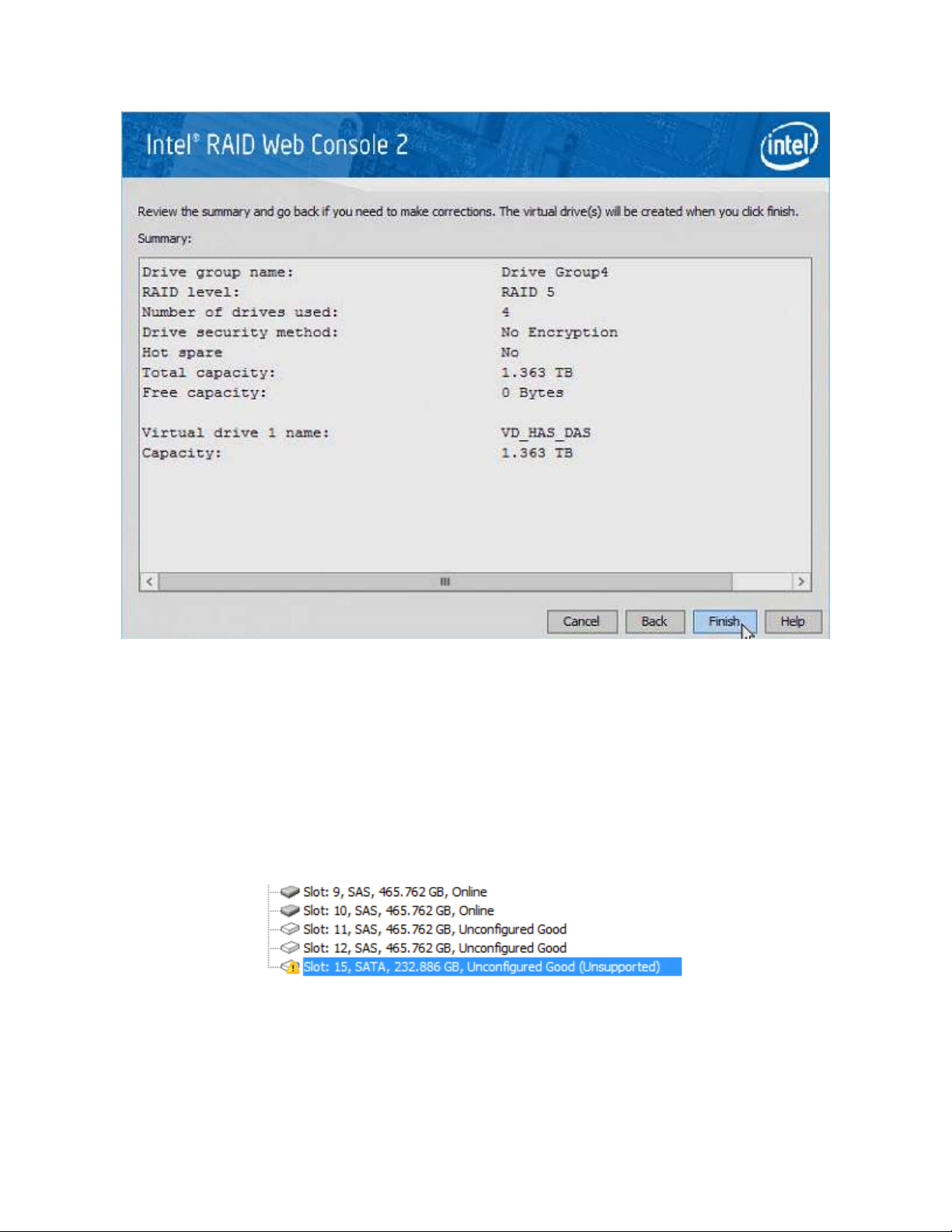
Figure 26 Create Virtual Drive Summary
11. Click Finish to complete the VD creation process.
12. Click OK when the Create Virtual Drive - complete message appears.
Unsupported Drives
Drives that are used in the Intel® RAID High Availability Storage solution must have Intel® RAID High
Availability Storage-compatible implementations of the SCSI-3 persistent reservation (PR) feature. Intel
maintains a list of drives that meet this requirement. If the RAID Web Console 2 (RWC2) utility finds a
drive that does not support the PR feature, it marks the drive as Unsupported, as shown in the following
figure.
Figure 27 Unsupported Drive in RWC2
36 Intel
®
High Availability Storage User Guide
Page 37

Intel® RAID High Availability Storage SSD Cache Support
The Intel® RAID High Availability Storage controller includes support for SSD Cache 1.0, a feature that
uses SAS SSD devices for read caching of frequently accessed read data. When a VD is enabled for the
SSD Cache feature, frequently read data regions of the VD are copied into the SSD when the SSD Cache
algorithm determines the region is a good candidate. When the data region is in the SSD Cache SSD
volume, the firmware can service related reads from the faster access SSD volume instead of the higher
latency hard disk VD. The SSD Cache feature uses a single SSD to service multiple VDs.
The Intel® RAID High Availability Storage solution requires the use of SAS SSDs that support SCSI-3
persistent reservations (PR) for SSD Cache VDs. Intel maintains a list of SAS SSD drives that meet the
Intel® RAID High Availability Storage requirements.
NOTE: A SSD Cache VD is not presented to the host operating system, and it does not move to the peer
controller node when a failover occurs. A SSD Cache VD possesses properties that are similar to a VD
with exclusive host access. Therefore, the SSD Cache volume does not cache read I/Os for VDs that
are managed by the peer controller node.
Follow these steps to create a SSD Cache 1.0 VD as part of a Intel® RAID High Availability Storage
configuration. The procedure automatically associates the SSD Cache volume with all existing shared
VDs in the configuration. Be sure that one or more SAS SSD drives are already present in the system.
Also, be sure you are using a version of RWC2 that supports Intel® RAID High Availability Storage.
1. In RWC2, open the physical view, right-click the controller, and select Create SSD Cache - SSD
Caching, as shown in the following figure.
Figure 28 Creating SSD Cache
Intel® High Availability Storage User Guide 37
Page 38

2. In the Drive Group window, set the SSD Cache RAID level and select one or more unconfigured SSD
drives. Use the Add button to place the selected drives into the drive group.
RAID 0 is the recommended RAID level for the SSD Cache volume.
The following figure shows the SSD Cache drive group.
Figure 29 Creating SSD Cache Drive Group 1
3. Click Create Drive Group and then click Next.
4. In the Create SSD Cache SSD Caching Virtual Drive window, update the SSD Caching VD name and
set the size as necessary.
The maximum allowable size for the SSD Cache volume is 512 GB. To achieve optimal read cache
performance, the recommended best practice is to make the size as large as possible with the available
SSDs, up to this limit.
38 Intel
®
High Availability Storage User Guide
Page 39

Figure 30 Creating SSD Cache Drive Group 2
5. Click Create Virtual Drive and then click Next.
6. In the Create SSD Cache SSD Caching Summary window, review the configuration and then click
Finish.
Intel® High Availability Storage User Guide 39
Page 40

Figure 31 Reviewing the Configuration
7. In the Create SSD Cache Complete box, click OK.
The CacheCache VD now appears on the Physical Tab of RWC2, as shown in the following figure. The
SSD Cache volume association with the drive groups appears in this view.
40 Intel
®
High Availability Storage User Guide
Page 41

Figure 32 New SSD Cache Drive Group
Intel® High Availability Storage User Guide 41
Page 42

4. System Administration
This chapter explains how to perform system administration tasks, such as planned failovers and updates
of the Intel® RAID High Availability Storage controller firmware.
High Availability Properties
The following figure shows the high availability properties that RWC2 displays on the Controller
Properties tab for a Intel® RAID High Availability Storage controller.
Figure 33 Controller Properties: High Availability Properties
A description of each high availability property follows:
Topology Type – A descriptor of the HA topology for which the Intel
®
RAID High Availability
Storage controller is currently configured (the default is Server Storage Cluster).
Maximum Controller Nodes – The maximum number of concurrent Intel
®
RAID High Availability
Storage controllers within the HA domain that the controller supports.
Domain ID – A unique number that identifies the HA domain in which the controller is currently
included. This field has a number if the cluster or peer controller is in active state.
Peer Controller Status – The current state of the peer controller.
Active: The peer controller is present and is participating in the HA domain.
Inactive: The peer controller is missing or has failed.
Incompatible: The peer controller is detected, but it has an incompatibility with the controller.
42 Intel
®
High Availability Storage User Guide
Page 43

Incompatibility Details – If the peer controller is incompatible, this field lists the cause of the
incompatibility.
Understanding Failover Operations
A failover operation in Intel® RAID High Availability Storage is the process by which VD management
transitions from one server/controller node to the peer server/controller node. A failover operation might
result from a user-initiated (planned) actions to move an application to a different controller node so that
maintenance activities can be performed, or the failover might be unintended (unplanned), resulting from
hardware or software component failure that blocks access to the storage devices. The following figures
shows an example of a failover operation of various drive groups and VDs from Server A to Server B.
Figure 34 Before Failover from Server A to Server B
Before failover, the cluster status is as follows in terms of the management of the drive group and the
VDs:
All VDs in A-DG0 (Server A - Drive Group 0) are managed by Server A.
VD3 in B-DG0 (Server B – Drive Group 0) is managed by Server B.
The SSD Cache VD (CC-VD) in A-CC is managed by Server A and services VDs in drive group A-
DG0.
Before failover, the operating system perspective is as follows:
Intel® High Availability Storage User Guide 43
Page 44

The operating system on Server A only sees VDs with shared host access and exclusive host access
to Server A.
The operating system on Server B only sees VDs with shared host access and exclusive host access
to Server B.
Before failover, the operating system perspective of I/O transactions is as follows:
Server A is handling I/O transactions that rely on A-DG0:VD1 and A-DG0:VD2.
Server B is handling I/O transactions that rely on A-DG0:VD0 and B-DG0:VD3.
Figure 35 After Failover from Server A to Server B
After failover, the cluster status is as follows in terms of the management of the drive group and the VDs:
All shared VDs in A-DG0 have failed over and are now managed by Server B.
VD3 in B-DG0 is still managed by Server B.
The SSD Cache VD (CC-VD) in A-CC now appears as a foreign VD on Server B but does not
service any VDs in A-DG0 or B-DG0.
After failover, the operating system perspective is as follows:
The operating system on Server B manages all shared VDs and any exclusive Server B VDs.
After failover, the operating system perspective of I/O transactions is as follows:
Failover Cluster Manager has moved the I/O transactions for VD2 on A-DG0 to Server B.
Server B continues to run I/O transactions on B-DG0:VD3.
44 Intel
®
High Availability Storage User Guide
Page 45

I/O transactions that rely on the exclusive A-DG0:VD1 on Server A fail because exclusive volumes
do not move with a failover.
NOTE: When Server A returns, the management and I/O paths of the pre-failover configurations are
automatically restored.
The following sections provide more detailed information about planned failover and unplanned failover.
Understanding and Using Planned Failover
A planned failover occurs when you deliberately transfer control of the drive groups from one controller
node to the other. The usual reason for initiating a planned failover is to perform some kind of
maintenance or upgrade on one of the controller nodes—for example, upgrading the controller firmware,
as described in the following section. A planned failover can occur when there is active data access to the
shared drive groups.
Before you start a planned failover on the Intel® RAID High Availability Storage system, be sure that no
processes are scheduled to run during that time. Be aware that system performance might be impacted
during the planned failover.
NOTE: Failed-over VDs with exclusive host access cannot be accessed unless the VD host access is set to
shared. Do not transition operating system boot volumes from EXCLUSIVE to SHARED.
Planned Failover in Windows Server 2012
Follow these steps to perform a planned failover on a Intel® RAID High Availability Storage system
running Windows Server 2012.
1. Create a backup of the data on the Intel® RAID High Availability Storage system.
2. In the Failover Cluster Manager snap-in, if the cluster that you want to manage is not displayed, in the
console tree, right-click Failover Cluster Manager, click Manage a Cluster, and then select or specify
the cluster that you want.
3. If the console tree is collapsed, expand the tree under the cluster that you want to configure.
4. Expand Services and Applications, and then click the name the virtual machine.
5. On the right-hand side of the screen, under Actions, click Move this service or application to
another node, and click the name of the other node.
As the virtual machine is moved, the status is displayed in the results panel (center panel). You can verify
that the move succeeded by inspecting the details of each node in the RAID management utility.
Planned Failover in Windows Server 2008 R2
Follow these steps to perform a planned failover on a Intel® RAID High Availability Storage system
running Windows Server 2008 R2.
1. Create a backup of the data on the Intel® RAID High Availability Storage system.
2. Open the Failover Cluster Manager, as shown in the following figure.
Intel® High Availability Storage User Guide 45
Page 46

Figure 36 Failover Cluster Manager
3. In the left panel, expand the tree to display the disks, as shown in the following figure.
Figure 37 Expand Tree
4. Right-click the entry in the Assigned To column in the center panel of the window.
A pop-up menu appears.
5. In the pop-up menu, select Move > Select Node, as shown in the following figure.
46 Intel
®
High Availability Storage User Guide
Page 47

Figure 38 Expand Tree
6. Select the node for the planned failover.
Understanding Unplanned Failover
An unplanned failover might occur if the controller in one of the controller nodes fails, or if the cable
from one controller node to the JBOD is accidentally disconnected. The Intel® RAID High Availability
Storage solution is designed to automatically switch to the other controller node when such an event
occurs, without any disruption of access to the data on the drive groups.
When an unplanned failover occurs, you must determine what caused the failover so you can fix the
problem.
NOTE: When the failed controller node returns, the management and I/O paths of the pre-failover
configurations are automatically restored.
Updating the Intel® RAID High Availability Storage Controller
Firmware
Follow these steps to update the firmware on the Intel® RAID High Availability Storage controller board.
You must perform the update only on the controller node that is not currently accessing the drive groups.
1. If necessary, perform a planned failover as described in the previous section to transfer control of the
drive groups to the other controller node.
2. Start the RWC2 utility on the controller node that does not currently own the cluster.
NOTE To determine which node currently owns the cluster in Windows Server 2012, follow the steps
in Section - Planned Failover in Windows Server 2008 R2, up to step 3, where information about the
cluster disks is displayed in the center panel. The current owner of the cluster is listed in the Owner
Node column.
3. In the left panel of the RWC2 window, click the icon of the controller that requires an upgrade.
4. In the RWC2 window, select Go To > Controller > Update Controller Firmware.
5. Click Browse to locate the .rom update file.
Intel® High Availability Storage User Guide 47
Page 48

6. After you locate the file, click Ok.
The RWC2 software displays the version of the existing firmware and the version of the new firmware
file.
7. When you are prompted to indicate whether you want to upgrade the firmware, click Yes.
The controller is updated with the new firmware code contained in the .rom file.
8. Reboot the controller node after the new firmware is flashed.
The new firmware does not take effect until reboot.
9. If desired, use planned failover to transfer control of the drive groups back to the controller node you
just upgraded.
10. Repeat this process for the other controller.
11. Restore the cluster to its non-failed-over mode.
Updating the Intel RAID Driver
To update the Intel RAID driver used in the clustering configuration, download the latest version of the
driver from the Intel website http://www.intel.com . Then follow these instructions for Windows Server
2008 R2 or Windows Server 2012.
Updating the Driver in Windows Server 2008 R2
As a recommended best practice, always back up system data before updating the driver, and then
perform a planned failover. These steps are recommended because a driver update requires a reboot of the
system.
1. Right-click Computer and select Properties.
2. Click Change Settings, as shown in the following figure.
48 Intel
®
High Availability Storage User Guide
Page 49
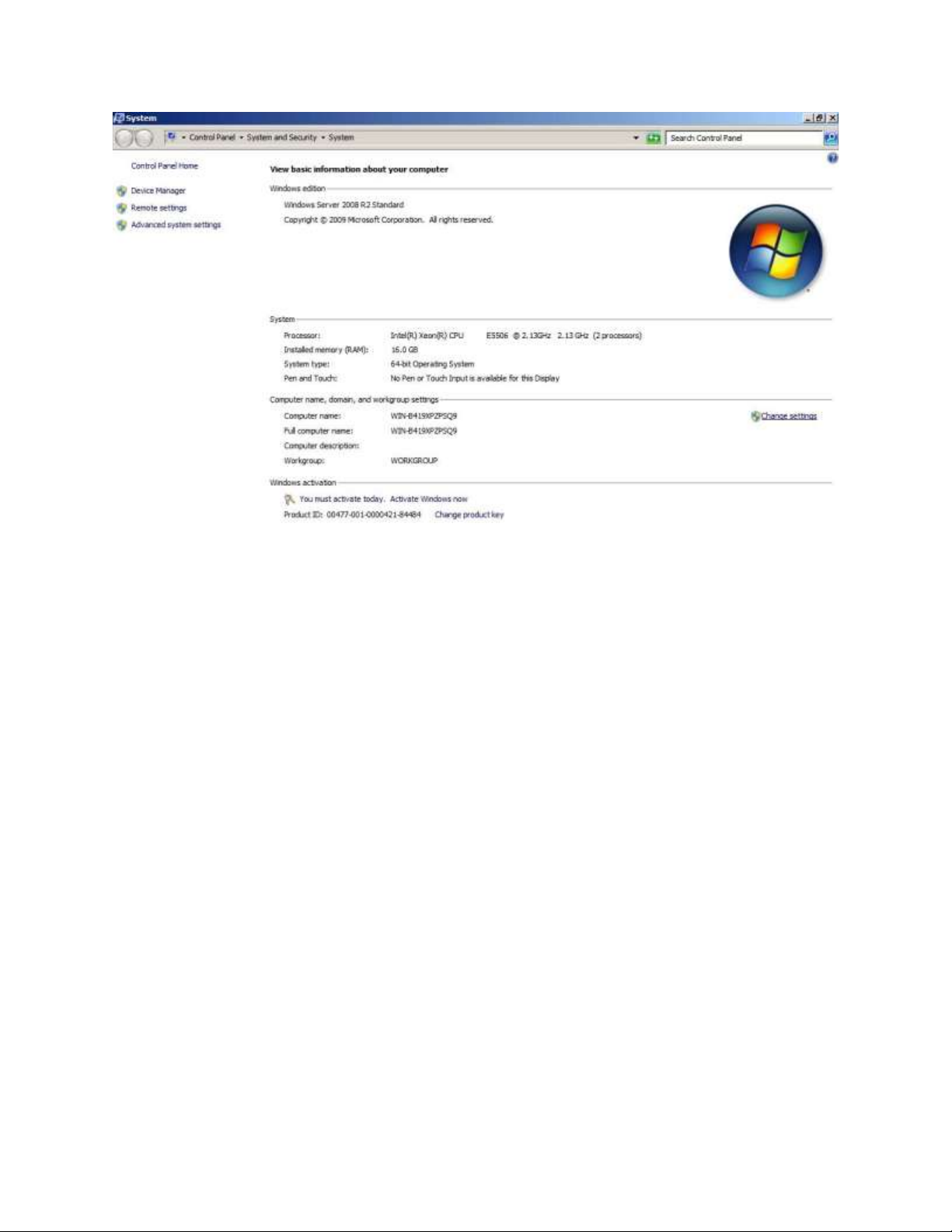
Figure 39 Windows Server 2008 R2 System Properties
3. Select the Hardware tab and click Device Manager.
4. Click Storage to expose the Intel® RAID High Availability Storage controller.
5. Right-click the Intel® RAID High Availability Storage controller and select Update Driver Software to
start the Driver Update wizard, as shown in the following figure.
Intel® High Availability Storage User Guide 49
Page 50

Figure 40 Updating the Driver Software
6. Follow the instructions in the wizard.
Updating the Driver in Windows Server 2012
As a recommended best practice, always back up system data before updating the driver, and then
perform a planned failover. These steps are recommended because a driver update requires a reboot of the
system.
1. Run Server Manager and select Local Server on the left panel.
2. Click the Tasks selection list on the right-hand side of the window, as shown in the following figure.
50 Intel
®
High Availability Storage User Guide
Page 51
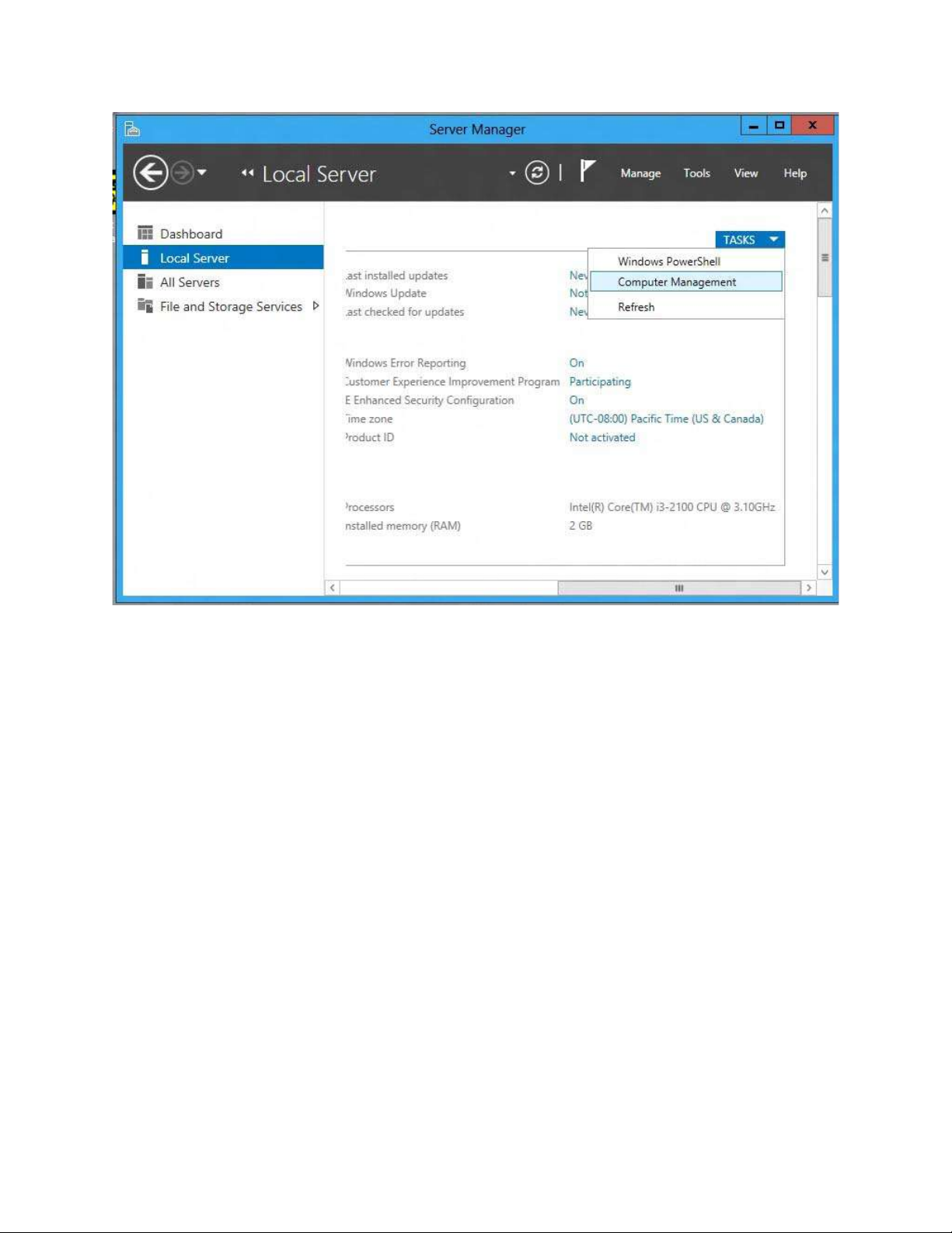
Figure 41 Updating the Driver Software
3. Select Computer Management, then click Device Manager.
4. Click Storage to expose the Intel® RAID High Availability Storage controller, as shown in the
following figure.
Intel® High Availability Storage User Guide 51
Page 52

Figure 42 Updating the Driver Software
5. Right-click the Intel® RAID High Availability Storage controller and select Update Driver Software
to start the Driver Update wizard.
6. Follow the instructions in the wizard.
Performing Preventative Measures on Disk Drives and VDs
The following drive and VD-level operations help to proactively detect disk drive and VD errors that
could potentially cause the failure of a controller node. For more information about these operations, refer
to the Intel(R) RAID Software User’s Guide.
Patrol Read – A patrol read periodically verifies all sectors of disk drives that are connected to a
controller, including the system reserved area in the RAID configured drives. You can run a patrol
read for all RAID levels and for all hot spare drives. A patrol read is initiated only when the
controller is idle for a defined time period and has no other background activities.
Consistency Check – You should periodically run a consistency check on fault-tolerant virtual drives
(RAID 1, RAID 5, RAID 6, RAID 10, RAID 50, and RAID 60 configurations; RAID 0 does not
provide data redundancy). A consistency check scans the virtual drives to determine whether the data
has become corrupted and needs to be restored.
For example, in a VD with parity, a consistency check computes the data on one drive and compares
the results to the contents of the parity drive. You must run a consistency check if you suspect that
the data on the VD might be corrupted.
NOTE: Be sure to back up the data before running a consistency check if you think the data might be
corrupted.
52 Intel
®
High Availability Storage User Guide
Page 53

Troubleshooting
This chapter contains useful information for troubleshooting a Intel® RAID High Availability Storage
system.
Reference Checklist of Required Intel® RAID High Availability
Storage Components
The following summary list shows the components required for a Intel® RAID High Availability Storage
configuration. For more detailed information, see Chapter 2: Hardware and Software Setup.
1. Intel® RAID High Availability Storage controllers: Intel® RAID High Availability Storage controller
that supports internal SFF-8087 mini-SAS ports (used in cluster-in-a-box configurations) or Intel® RAID
High Availability Storage controller with external SFF-8088 mini-SAS ports (used with discrete
computers).
2. An RWC2 version that includes Intel® RAID High Availability Storage feature support.
3. A CmdTool2 version that includes Intel® RAID High Availability Storage feature support.
4. SAS drives that fully support SCSI-3 persistent reservations (no SATA drives).
5. SAS expanders with HA-specific dual 4-lane SAS connections for the initiators and dual-port
connections to the drives.
6. Operating systems that support clustering with all of the necessary services, option selections, and
patches. (Windows Server 2008 R2 or Windows Server 2012)
7. Two local area networks: one private, one public.
Verifying Intel® RAID High Availability Storage Support in Tools
and the OS Driver
Not all versions of RWC2 support Intel® RAID High Availability Storage. The RWC2 versions that
include support for Intel® RAID High Availability Storage have specific references to clustering. It is not
always possible to determine the level of support from the RWC2 version number. Instead, look for the
RWC2 user interface features that indicate clustering support. If the second item in the RWC2 Properties
box on the dashboard for the Intel® RAID High Availability Storage controller is High Availability
Cluster status, the version supports Intel® RAID High Availability Storage. This entry does not appear
on versions of RWC2 without Intel® RAID High Availability Storage support.
You can also check the RWC2 Create Virtual Drive wizard. A Share Virtual Drive check box appears
only if the RWC2 version supports clustering, as shown in the following figure.
Intel® High Availability Storage User Guide 53
Page 54

Figure 43 Share Virtual Drive Property
Intel® RAID High Availability Storage versions of RWC2 also require an Intel® RAID High Availability
Storage-capable OS driver to present Intel® RAID High Availability Storage features. The in-box driver
for Windows Server 2012, version 5.2.122.0 4/3/2012 does not present Intel® RAID High Availability
Storage features in RWC2.
NOTE: Intel tested the Intel® RAID High Availability Storage solution with the release to
manufacturing (RTM) build of Windows Server 2012. To determine the Windows version on your
system, open a command window (not PowerShell), and use the ver command to see the Windows build
number. To find the Windows command line, move the mouse to expose search, search for cmd, and
run it.
To determine if your version of CmdTool2 supports Intel® RAID High Availability Storage, enter this
help command:
CmdTool2 help cfgldadd
If the help text that is returned includes information about the -Exclusive parameter, your version of
CmdTool2 supports Intel® RAID High Availability Storage.
54 Intel
®
High Availability Storage User Guide
Page 55

Confirming SAS Connections
The high availability aspect of Intel® RAID High Availability Storage is based upon redundant SAS data
paths between the clustered nodes and the disk drives. If all of the components in the SAS data path are
configured and connected properly, each Intel® RAID High Availability Storage controller has two SAS
addresses for every drive, when viewed from the Intel® RAID High Availability Storage controllers.
This section explains how to use three tools (CmdTool2, Intel® RAID BIOS Console, and RWC2) to
confirm the correctness of the SAS data paths.
Using Intel® RAID BIOS Console to View Connections for Controllers,
Expanders, and Drives
Use the Physical View in Intel® RAID BIOS Console to confirm the connections between the controllers
and expanders in the Intel® RAID High Availability Storage system. As shown in the following figure, if
both expanders are running, the view in Intel® RAID BIOS Console from one of the nodes includes the
other Intel® RAID High Availability Storage RAID controller (Processor 8 in the figure), the two
expanders, and any drives, as shown in the following figure.
Figure 44 Intel® RAID BIOS Console Physical View
If the other node is powered off, the other RAID controller does not appear in Intel® RAID BIOS
Console. In cluster-in-a-box configurations, the other expander is powered by the other node. Therefore, it
appears only when both nodes are running. Devices can appear and disappear while the system is running,
as connections are changed. Use the Intel® RAID BIOS Console rescan feature to rediscover the devices
and topology after a connection change.
Using Intel® RAID BIOS Console to Verify Dual-Ported SAS Addresses to
Disk Drives
Use the Drive Properties View in Intel® RAID BIOS Console to confirm that each SAS drive displays
two SAS addresses. In a Intel® RAID High Availability Storage system that is properly cabled and
configured, every drive should have two SAS addresses. If the system lacks redundant SAS data paths,
the Intel® RAID BIOS Console shows only one SAS address on the screen. For information about
redundant cabling configurations, see Section - Cabling Configurations.
To check the drive SAS addresses, open the Physical View on the home page of Intel® RAID BIOS
Console, and click a drive link. On the Disk Properties page, click Next. When the redundant SAS data
paths are missing, this second view of drive properties shows only one SAS address in the left panel, as in
the following figure.
Intel® High Availability Storage User Guide 55
Page 56

Figure 45 Redundant SAS Data Paths Are Missing
The following figure shows the correct view with two drive SAS addresses.
56 Intel
®
High Availability Storage User Guide
Page 57

Figure 46 Redundant SAS Data Paths Are Present
Using CmdTool2 to Verify Dual-Ported SAS Addresses to Disk Drives
The CmdTool2 configuration display command (-cfgdsply) returns many lines of information, including a
summary for each physical disk. To confirm the controller discovery of both SAS addresses for a single
drive, examine the CmdTool2 configuration text for the drive information following the Physical Disk
line. Following is the CmdTool2 configuration display command followed by a portion of the information
presented for each physical drive, up to the lines that show the drive’s SAS addresses. If only one of the
drive’s SAS ports was discovered, the second SAS address is listed as 0x0. If both drive SAS ports were
discovered, the second drive port SAS address is identical to the first except for the last hexadecimal digit,
which always has a value of plus or minus 1 relative to SAS Address(0).
The syntax of the CmdTool2 command is as follows:
CmdTool2 –cfgdsply –a0
The returned information relating to the physical disk is as follows. Some of the other preceding text is
removed for brevity. The dual SAS addresses are listed at the end.
Physical Disk: 0
Enclosure Device ID: 65
Slot Number: 1
Drive's postion: DiskGroup: 0, Span: 0, Arm: 0
Enclosure position: 0
Intel® High Availability Storage User Guide 57
Page 58

Device Id: 57
WWN: 5000C500178C4488
Sequence Number: 16
Media Error Count: 0
Other Error Count: 1961
Predictive Failure Count: 0
Last Predictive Failure Event Seq Number: 0
PD Type: SAS
Raw Size: 68.366 GB [0x88bb998 Sectors]
Non Coerced Size: 67.866 GB [0x87bb998 Sectors]
Coerced Size: 67.843 GB [0x87b0000 Sectors]
Firmware state: Online, Spun Up
Device Firmware Level: 0005
Shield Counter: 0
Successful diagnostics completion on : N/A
SAS Address(0): 0x5000c500178c4489
SAS Address(1): 0x5000c500178c448a
Using RWC2 to Verify Dual-Ported SAS Addresses to Disk Drives
When the Intel® RAID High Availability Storage system is running, you can use RWC2 to verify the dual
SAS paths to disk drives in the Intel® RAID High Availability Storage configuration by following these
steps:
1. Start RWC2 and access the Physical tab for the controller.
2. Click a drive in the left panel to view the Properties tab for the drive.
3. Look at the SAS Address fields.
As shown in the following figure, a correctly configured and running Intel® RAID High Availability
Storage cluster with both nodes active displays dual SAS addresses on the drives and dual 4-lane SAS
connections on the controller.
58 Intel
®
High Availability Storage User Guide
Page 59

Figure 47 Redundant SAS Connections Displayed in RWC2
Problem
Possible
Cause
A drive is reported as
Unsupported, and the drive
cannot be used in a drive group.
The drive is not a SAS drive, or it
does not support SCSI-3 PR.
Use a SAS drive that supports
SCSI-3 PR. Refer to the list of
compatible SAS drives on the
Intel web site, or ask your drive
vendor.
One or more of the following
error messages appear after you
run the Microsoft Cluster
Validation tool:
Two I/O paths are not
established between the
controller and drive.
This build of the Windows
Confirm that device ports and
all cabling connections between
the controller and drive are
correct and are functioning
properly. See Section -
Understanding SSD Cache Behavior During a Failover
A SSD Cache VD possesses properties that are similar to a VD with exclusive host access, and it is not
presented to the host operating system. Therefore, the SSD Cache volume does not cache read I/Os for
VDs that are managed by the peer controller node.
Foreign import of a SSD Cache VD is not permitted. To migrate a SSD Cache VD from one controller
node to another, you must delete it from the controller node that currently manages it and then recreate
the SSD Cache VD on the peer controller node.
Error Situations and Solutions
The following table lists problems that you might encounter in a Intel® RAID High Availability Storage
configuration, along with possible causes and solutions. The highlighted entry is especially important;
when updating the controller firmware, you must be sure that the version of the firmware supports high
availability features.
Intel® High Availability Storage User Guide 59
Page 60

Disk bus type does not
support clustering. Disk
partition style is MBR. Disk
partition type is BASIC.
No disks were found on
which to perform cluster
validation tests.
operating system does not
natively support internal RAID
controllers for clustering.
Confirming SAS Connections.
Confirm that the version (or
the current settings) of the
operating system supports
internal RAID controllers.
When booting a controller node,
the controller reports that it is
entering Safe Mode. After
entering Safe Mode, the
controller does not report the
presence of any drives or
devices.
controller parameter is detected.
The peer controller is prevented
from entering the HA domain.
compatible with the controller in
the HA domain. Entering Safe
Mode protects the VDs by
blocking access to the controller
to allow for correction of the
incompatibility.
have settings that do not match
the controller. To correct this
situation, update the firmware for
the peer controller and the other
controller, or both, to ensure that
they are at the same firmware
version.
ntroller hardware
does not exactly match the
controller. To correct this
situation, replace the peer
controller with a unit that
matches the controller hardware.
The Intel management
applications do not present or
report the HA options and
properties.
The version of the management
applications might not be HAcompatible.
Obtain an HA-compatible
version of the management
application from the Intel web
site, or contact an Intel support
representative.
Drives are not reported in a
consistent manner.
Improper connections might
impact the order in which the
drives are discovered.
Make sure you are following the
cabling configuration guidelines
listed in Section - Cabling
Configurations.
The management application
does not report a VD or disk
group, but the VD or disk group
is visible to the OS.
The shared VD is managed by
the peer controller.
The VD or drive group can be
seen and managed on the other
controller node. Log in or open a
terminal on the other controller
node.
60 Intel
®
High Availability Storage User Guide
 Loading...