

Page 1

Intel® Server Products and Solutions
Intel® Server S2600WF Product Family Configuration Guide
Intel® Server Board S2600WF Product Family
Intel® Server Chassis R1000WF & R2000WF Product Families
Intel® Server System R1000WF & R2000WF Product Families
Intel® Server System R2000WFTF Product Family
A reference document used to identify available Intel server building blocks, integrated systems, accessories, and
spare parts associated with the Intel
®
Server S2600WF product family.
Rev 1.5
August 2018
Page 2

<Blank Page>
Page 3

Intel® Server S2600WF Product Family Configuration Guide and Spares/Accessories List
3
Document Revision History
Date Published
Revision
Revision Change Description
June 2017
1.0
Production Release
July 2017
1.1
Updated iPC A2U8X25S3DPDK2
Updated Cable Kit information for 4 port switch for 1U systems
Changes:
1.2 – Added 1U Back Panel Illustration
1.3 – Added 2U Back Panel Illustration
6 & 7 – Updated A2UHANDLKIT Illustration
8 – Added Intel® Visual Compute Accelerators VCA1585LMV
August 2017
1.2
Changes:
- Updated product ordering information for AXXRMM4LITE2 Intel® Remote Management Module 4 Lite Activation Key
- Updated the cables required for a second fabric processor with AWF1PFABKITM Mez Fabric Carrier Kit and AWF1PFABKITP
PCIe Fabric Carrier Kit
- Updated product ordering information for AXXRMFBU6
- Updated RAID information on the section Optional Intel Accessories
- Updated note on the R2000WFXXX description, delete optical drive support
- Update document by removing the A2UHANDLKIT3 handle
- Updated SAS drive configuration note
- Updated 2U system information on Hot Swap drive bays iPC F2U12X35S3PH
- Updated information on the table Drive Bay #1, 2 & 3 - SAS / SATA / NVMe Cable Guide for Switch Add in Cards
- Updated RAID info on S2600WFT SKU: Intel® Embedded Server RAID Technology 2 (ESRT2) 1.60 with optional RAID 5 key
support
- Updated Images:
- A2U8X25S3DPDK2
- A2U8X25S3PHS
- A2UREARHSDK2
October 2017
1.3
Changes:
- Added S2600WFQ information SKU on Products Family Features Table
- Added S2600WFQ information on Available Server Board, Chassis, and System SKU Summary
- Added S2600WFQ SKU on Intel® Server Board S2600WF Product Family Options
- Added S2600WFQ SKUs system information on Intel® Server System R2000WF Product Family SKUs
- Added R2312WFQZS to the section 2U 12 x 3.5” - R2312WFxxx SAS / SATA Data Cable Guide (with No SAS Expander)
- Added R2312WFQZS to the section 2U 12 x 3.5” - R2312WTxxx SAS / SATA Data Cable Guide (with SAS Expander)
- Updated 2U systems have 3 riser card A2UL8RISER2 included on the configuration
Page 4

Intel® Server S2600WF Product Family Configuration Guide and Spares/Accessories List
4
- Updated product ordering information for RSP3MD088F
- Updated Chipset information for S2600WFQ on the table The Intel® Server Board S2600WF family
- Updated Chipset information and notes for Intel Server Board S2600WFQ
- Updated Order Code Information for System R2312WFQZS
- Updated Table 3. Product Family Reference Collaterals
- Updated image for X527DA40CPG1P5
- Updated product name for AXX1300TCRPS
- Updated label ‘Intel® OCP Module - See Chapter 5.5 for available options’ in all 1U and 2U systems
- Added a note of only S2600WF0 and S2600WFQ support on the Quad OCP Expansion Modules
- Added an ‘Important note’ on the Product Section under the products: AWF1PFABKITM and AWF1PFABKITP
- Added Adjustment note on the Product Description section under the products: A1UFULLRAIL, A1USHRTRAIL, AXXFULLRAIL,
AXXSHRTRAIL
- Added 1 x A2UX8X4RISER on the 2U systems: R2312WF0NP, R2312WFTZS, R2312WFQZS, R2224WFQZS, R2224WFTZS
- Updated SAS / SATA / NVMe Data Cable Guide section
- Corrected all 2U system BOMs and product feature reference tables to include 3
rd
Riser card option
October 2017
1.3.1
Changes:
- Corrected Kit content definitions for the two IFT Carrier Accessory Kits
- Added 1U/2U fabric cpu clip accessory kit FXXCPUCLIPF
- Made additional corrections/clarification to NVMe Cable Guide sections.
- Updated Chassis Illustrations in Cable Guide sections
- SAS Cable support clarification for 1U system configurations that include SAS ROC Modules with vertical connectors
December 2017
1.3.2
Corrected NVMe cable lengths for onboard Oculink connectors routed to Drive Bay 1 of 2.5” drive configurations.
January 2018
1.4
Changes:
- Added 1U/2U Virtual Raid on CPU (VROC) key for Intel SSD Only
- Added 1U 4 port Switch accessory cable kit A1U4PSWCXCVK
- Updated information on the table 1U 8 x 2.5” – R1208WFxxx SAS / SATA / NVMe Data Cable Guide for Switch
- Updated information for cable AXXCBL850HDHRS
- Updated Maximum Supported Processor Thermal Design Power (TDP) for Table 6. R2000WF Features
- Corrected the MM# for A2U8X25S3DPDK2
- Corrected the MM# for RSP3GD016J
August 2018
1.5
Changes:
- Added R2000WFTF SKU information
- Added DVDROM Drive AXXSATADVDROM
- Added DVD+/-RW ROM Drive AXXSATADVDRWROM
- Added 4-Port PCIe SSD Retimer AIC AXXP3RTX16040
- Added accesory cable kit A1U4PRTCXCXK
Page 5

Intel® Server S2600WF Product Family Configuration Guide and Spares/Accessories List
5
- Added accesory cable kit A2U4PRTCXCXK
- Updated information on the table 4.4 1U 8 x 2.5” – R1208WFxxx SAS / SATA / NVMe Data Cable Guide for NVMe and Retimer
- Updated information on table 4.6.1 2U 12 x 3.5” - R2312WFxxx SAS / SATA / NVMe Data Cable Guide (with No SAS Expander)
for Up to 2 x NVMe
- Updated information on table 4.6.2 2U 12 x 3.5” - R2312WTxxx SAS / SATA / NVMe Data Cable Guide (with SAS Expander) for
Up to 2 x NVMe
- Updated information on table 4.7.1.1 Drive Bay Module #1 – SAS / SATA Cable Guide for SATA and SAS
- Updated information on table 4.7.1.2 Drive Bay Module # 1 – NVMe Cable Guide for Onboard PCIe OCuLink to Drive Bay
Module (BP) #1 Cable Kits and PCIe Retimer Card
- Updated information on table 4.7.3.2 Drive Bay Module #3 – NVMe Cable Guide for PCIe Retimer Card
- Updated MM# for R1208WFTYS
- Updated MM# for R2308WFTZS
- Updated MM# for R2208WF0ZS
- Updated MM# for R2208WFTZS
- Updated MM# for R2208WFQZS
- Updated MM# for R2312WF0NP
- Updated MM# for R2312WFTZS
Page 6

Intel® Server S2600WF Product Family Configuration Guide and Spares/Accessories List
6
Disclaimer
Intel technologies’ features and benefits depend on system configuration and may require enabled hardware, software, or service activation. Performance varies depending on
system configuration. No computer system can be absolutely secure. Check with your system manufacturer or retailer or learn more at intel.com.
You may not use or facilitate the use of this document in connection with any infringement or other legal analysis concerning Intel products described herein. You agree to grant
Intel a non-exclusive, royalty-free license to any patent claim thereafter drafted which includes subject matter disclosed herein.
No license (express or implied, by estoppel or otherwise) to any intellectual property rights is granted by this document.
The products described may contain design defects or errors known as errata which may cause the product to deviate from published specifications. Current characterized errata
are available on request.
Intel disclaims all express and implied warranties, including without limitation, the implied warranties of merchantability, fitness
for a particular purpose, and non-infringement, as well as any warranty arising from course of performance, course of dealing, or usage in trade.
This document contains information on products, services and/or processes in development. All information provided here is subject to change without notice. Contact your Intel
representative to obtain the latest Intel product specifications.
Copies of documents which have an order number and are referenced in this document may be obtained by calling 1-800-548-4725 or by visiting
www.intel.com/design/literature.htm.
Intel, the Intel logo, Xeon, and Xeon Phi are trademarks of Intel Corporation or its subsidiaries in the U.S. and/or other countries.
*Other names and brands may be claimed as the property of others.
© Intel Corporation
Page 7

Intel® Server S2600WF Product Family Configuration Guide and Spares/Accessories List
7
Table of Contents
1. Intel Server Family Overview ................................................................................................................................. 11
1.1 Intel Server Board S2600WF Product Family .................................................................................................... 15
1.2 Intel Server Board S2600WFTF Product Family ............................................................................................... 18
1.3 Intel Server System R1000WF Product Family ................................................................................................. 21
1.4 Intel® Server System R2000WF Product Family ............................................................................................... 24
1.5 Available Server Board, Chassis, and System SKU Summary ...................................................................... 29
1.6 Intel® Server System R2000WFTF Product Family .......................................................................................... 32
2. Server Building Block Options .............................................................................................................................. 36
2.1 Intel® Server Board S2600WF Product Family Options ................................................................................. 37
2.2 Intel® Server Chassis Product Family Options ................................................................................................... 39
2.3 Intel Power Supply Modules and Power Cords ................................................................................................. 42
3. Server System Configuration ................................................................................................................................. 43
3.1 Intel® Server System R1000WF Product Family SKUs – (1U Rack Mount System) ........................... 44
3.2 Intel® Server System R2000WF Product Family SKUs – (2U Rack Mount System) ........................... 48
4. SAS / SATA / NVMe Data Cable Guide ................................................................................................................. 64
4.1 Cable Connector Types ............................................................................................................................................... 65
4.2 1U / 2U Server System SAS / SATA / NVMe Cable Kits ................................................................................. 67
4.3 1U 4 x 3.5” – R1304WFxxx SAS / SATA Data Cable Guide............................................................................ 74
4.4 1U 8 x 2.5” – R1208WFxxx SAS / SATA / NVMe Data Cable Guide ........................................................... 75
4.5 2U 8 x 3.5” – R2308WFxxx SAS / SATA Data Cable Guide............................................................................ 76
4.6 2U 12 x 3.5 – R2312WFxxx SAS / SATA / NVMe Data Cable Guide .......................................................... 77
4.6.1 2U 12 x 3.5” - R2312WFxxx SAS / SATA / NVMe Data Cable Guide (with No SAS Expander) ....... 77
4.6.2 2U 12 x 3.5” - R2312WTxxx SAS / SATA / NVMe Data Cable Guide (with SAS Expander) .............. 78
4.7 2U 2.5” Front Mount Drive Bay Cable Guide ....................................................................................................... 80
4.7.1 2U - 8x2.5” Drive Bay Module #1 – Cable Guide (with no SAS Expander) ............................................. 81
4.7.2 2U - 8x2.5” Drive Bay Module #2 – Cable Guide (with no SAS Expander) ............................................. 84
4.7.3 2U - 8x2.5” Drive Bay Module #3 – Cable Guide (with no SAS Expander) ............................................. 86
4.7.4 2U 2.5” Front Mount Drive Configurations – Cable Guide (with SAS Expander) ................................. 89
5. Intel 1U / 2U System Optional Accessories ........................................................................................................ 91
Page 8

Intel® Server S2600WF Product Family Configuration Guide and Spares/Accessories List
8
5.1 2U Rear Mount Hot Swap Drive Bay Accessory Kit – iPC A2UREARHSDK2 ........................................... 91
5.2 1U / 2U PCIe* Riser Card Accessory/Spare FRU Options .............................................................................. 92
5.2.1 1U Riser Card Options .................................................................................................................................................. 92
5.2.2 2U Riser Card Options .................................................................................................................................................. 93
5.3 2U 8x2.5” Drive Bay Module Options .................................................................................................................... 95
5.4 OCP Expansion Modules ............................................................................................................................................. 97
5.5 Intel® SAS RAID Add-in Cards, Modules, and Accessories ............................................................................ 99
5.5.1 Intel® Integrated RAID Module RMS3 Product Family – SAS 3.0 (12 Gb/s) ........................................... 99
5.5.2 Intel® RAID Controller Add-in Cards - SAS 3.0 (12Gb/s)............................................................................. 103
5.5.3 Intel® RAID Accessory Options .............................................................................................................................. 107
5.6 Intel Power Supply Modules and Power Cords .............................................................................................. 111
5.7 1U / 2U Rack Mount Kits .......................................................................................................................................... 112
iPC - AXX2POSTBRCKT ............................................................................................................................................................... 113
6. 1U / 2U Miscellaneous Accessory Options ....................................................................................................... 115
7. 1U / 2U Spare and Replacement Parts (FRUs) ................................................................................................. 123
8. Intel® Visual Compute Accelerators ................................................................................................................... 126
Appendix A. Glossary of Terms .............................................................................................................................. 127
Page 9

Intel® Server S2600WF Product Family Configuration Guide and Spares/Accessories List
9
List of Tables
Table 1. Intel® Xeon® Processor scalable family - feature comparison table .................................................................. 12
Table 2. Intel® Xeon® Processor scalable family w/ integrated Intel® omni-path fabric – features table ............ 13
Table 3. Product family reference collaterals ............................................................................................................................... 14
Table 4. Server board product family features table ................................................................................................................. 16
Table 5. Intel® Server Board S2600WFTF product family features table .......................................................................... 19
Table 6. Intel® Server System R1000WF product family features table ...................................................................... 23
Table 7. Intel® Server System R2000WF product family features table ....................................................................... 27
Table 8. Server board product family summary .......................................................................................................................... 29
Table 9. Server chassis (KDK) product family summary ........................................................................................................... 29
Table 10. Server system (BIK) product family summary....................................................................................................... 30
Table 11. Intel® Server System R2000WFTF product family features table .................................................................... 34
Table 12. Intel® Server Board S2600WF product family options ......................................................................................... 37
Table 13.Data cable connector identification ............................................................................................................................... 67
Table 14. SATA / SAS / NVMe data cable kit description and order information .......................................................... 68
Page 10

Intel® Server S2600WF Product Family Configuration Guide and Spares/Accessories List
10
List of Figures
Figure 1. Intel® Server Board S2600WF onboard features ...................................................................................................... 15
Figure 2. Intel® Server Board S2600WFTF onboard features ................................................................................................. 18
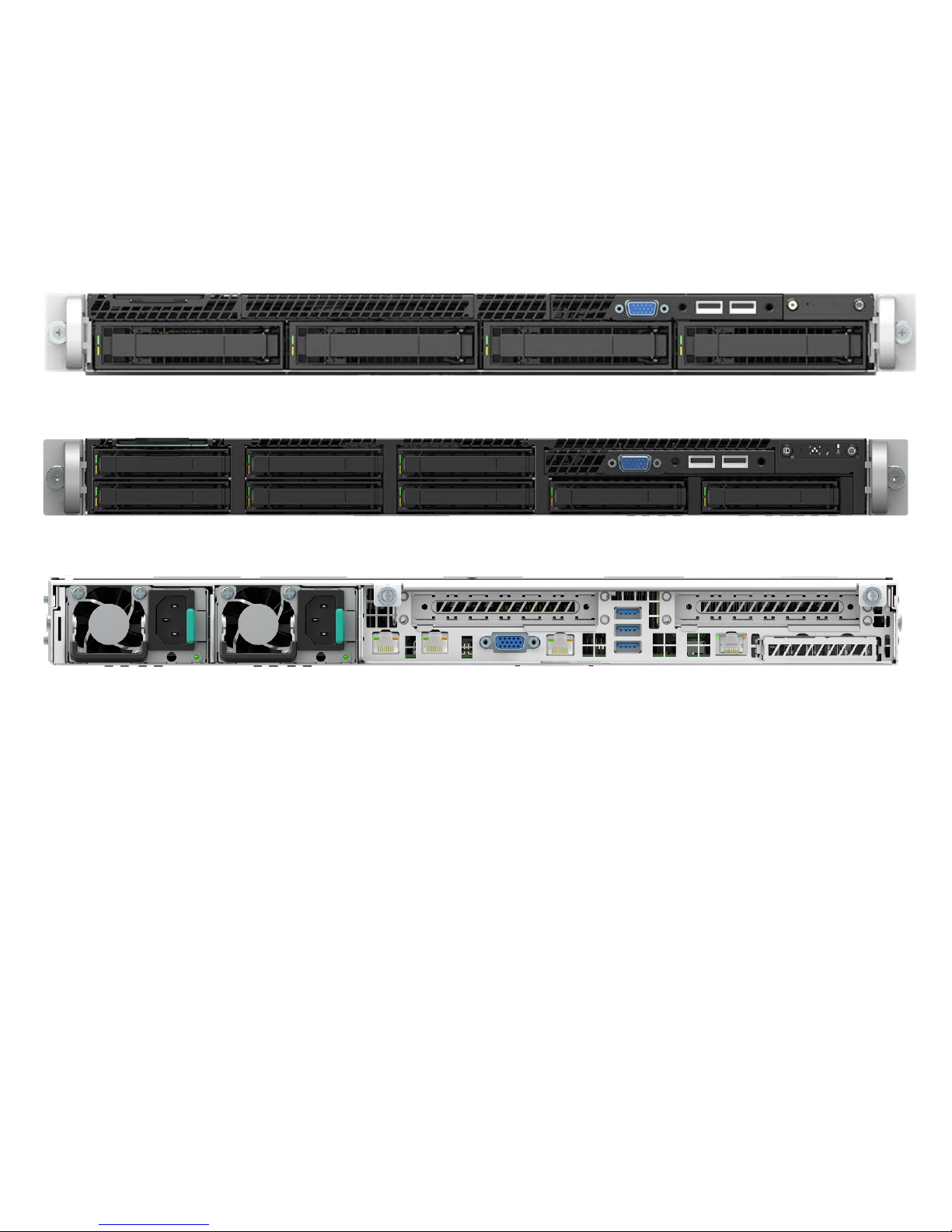
Figure 3. Intel® Server System R1000WF feature set identification .................................................................................... 21
Figure 4. 1U, 3.5” x 4 drive configuration (Intel® Server System R1304xxx) .................................................................... 22
Figure 5. 1U, 2.5" x 8 drive configuration (Intel® Server System R1208WFxxx) .............................................................. 22
Figure 6. 1U system back panel .......................................................................................................................................................... 22
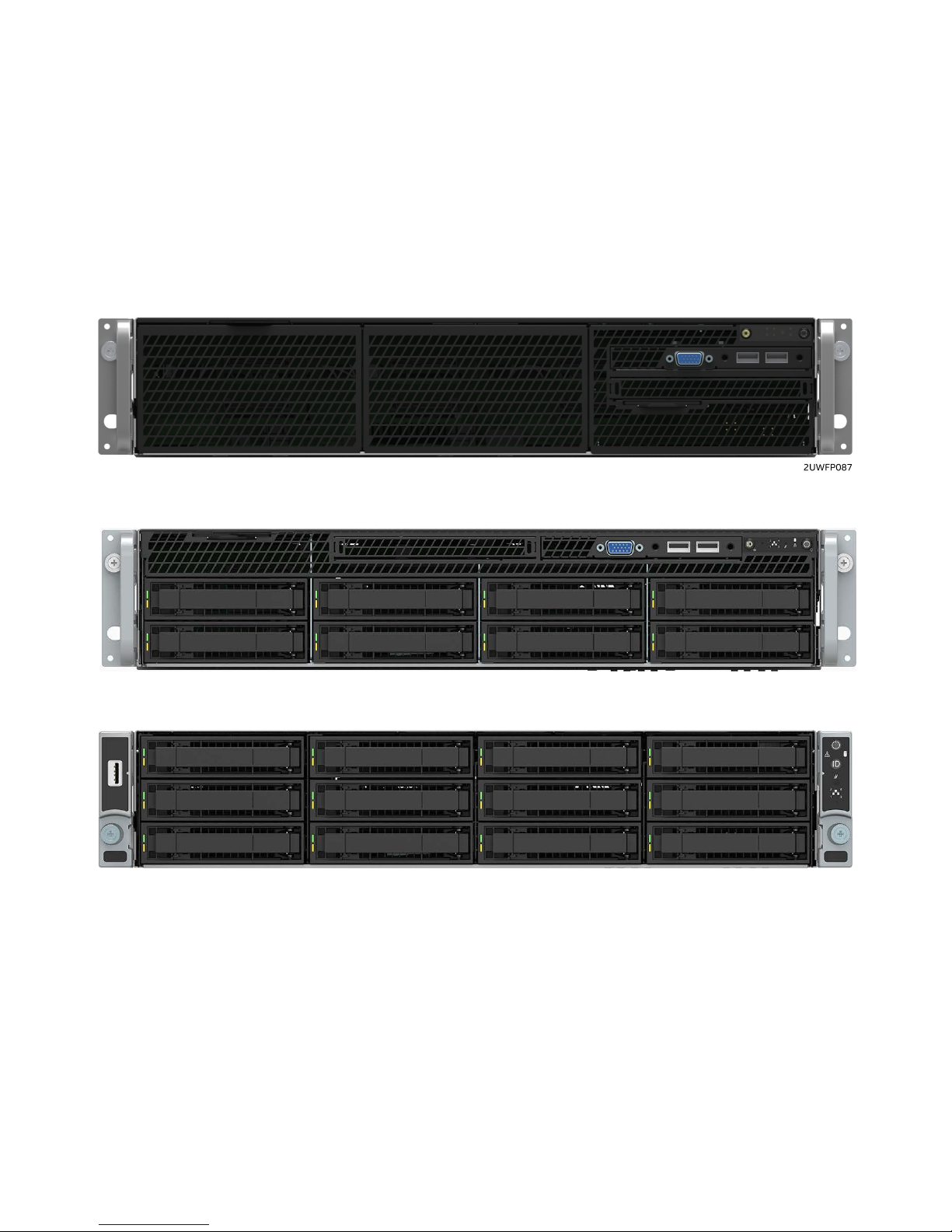
Figure 7. Intel® Server System R2000WF feature set identification .................................................................................... 24
Figure 8. 2U, No drive bays, chassis only building block (Intel® Server Chassis R2000WFxxx) ............................... 25
Figure 9. 2U, 3.5" x 8 drive configuration (Intel® Server System R2308WFxxx) .............................................................. 25
Figure 10. 2U, 3.5" x 12 drive configuration (Intel® Server System R2312WFxxx – storage configuration) ....... 25
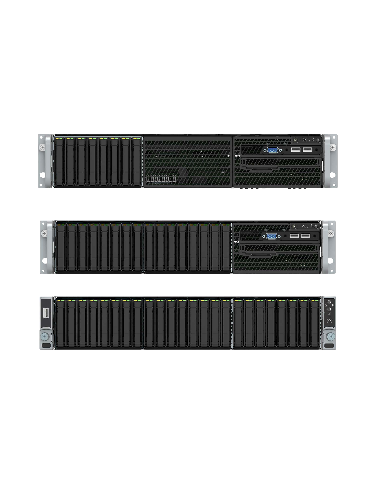
Figure 11. 2U, 2.5" x 8 drive configuration (Intel® Server System R2208WFxxx) ........................................................... 26
Figure 12. 2U, 2.5" x 16 drive configuration (Intel® Server System R2208WFxxx + 8 drive accessory kit) ......... 26
Figure 13. 2U, 2.5" x 24 drive configuration (Intel® Server System R2224WFxxx – storage configuration) ....... 26
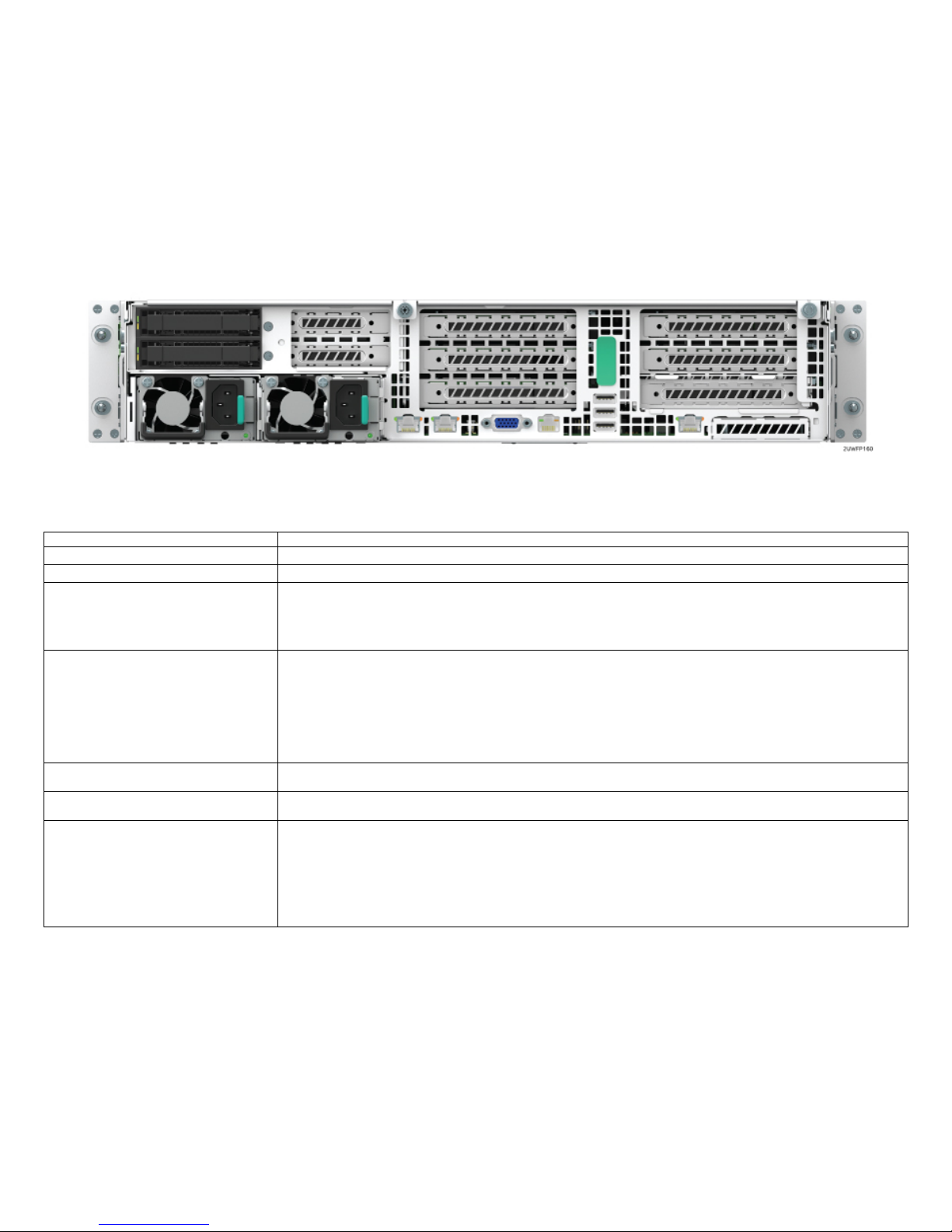
Figure 14. 2U System back panel with optional 2 x 2.5” hot swap drive bay .................................................................. 27
Figure 15. Intel® Server System R2000WFTF feature set identification ............................................................................ 32
Figure 16. 2U, 2.5" x 8 drive configuration (Intel® Server System LFRB2208WFTFxxx) .............................................. 33
Figure 17. 2U, 3.5" x 12 drive configuration (Intel® Server System LFRB2312WFTFxxx – storage configuration)33
Figure 18. 2U System Back Panel with Optional 2 x 2.5” Hot Swap Drive Bay ........................................................... 33
Figure 19. Intel® Server System R1000WF Product Family ..................................................................................................... 44
Figure 20. R2308WFxxx SAS / SATA backplane .......................................................................................................................... 76
Figure 21. R2312WFxxx SAS / SATA backplane .......................................................................................................................... 77
Figure 22. R2208WF based system with Front I/O Module Bay Assembly ...................................................................... 95
Figure 23. 2U 2.5" Drive identification for each drive bay ....................................................................................................... 95
Figure 24. OCP Module Installation ................................................................................................................................................... 97
Page 11
Intel® Server S2600WF Product Family Configuration Guide and Spares/Accessories List
11
1. Intel Server Family Overview
This document provides a catalogue of available Intel server products, accessories, and spares associated with the following Intel server product
family.
The Intel® Server S2600WF product family is offered as both building block options and integrated systems. The product family consists of the
following:
Server Building Blocks:
• Intel® Server Board S2600WF Family – A family of Server Board only products (Server building block option and spare FRU)
• Intel® Server Chassis R1000WF product family – A family of 1U Rack Mount Server Chassis only products
• Intel® Server Chassis R2000WF product family – A family of 2U Rack Mount Server Chassis only products
Intel® Server S2600WF Product Family
Intel® Server Board S2600WF Family
Intel® Server Chassis R1000WF
Product Family
Intel® Server Chassis R2000WF
Product Family
Intel® Server System R1000WF
Product Family
Intel® Server System R2000WF
Product Family
Intel® Server System
R2000WFTF Product Family
Page 12

Intel® Server S2600WF Product Family Configuration Guide and Spares/Accessories List
12
Integrated Server Systems:
• Intel® Server System R1000WF product family – A family of 1U Rack Mount server chassis integrated with an Intel® Server Board
S2600WF option
• Intel® Server System R2000WF product family – A family of 2U Rack Mount server chassis integrated with an Intel® Server Board
S2600WF option
• Intel® Server System R2000WFTF product family – A family of 2U Rack Mount server chassis integrated at level L9 with an Intel® Server
Board S2600WFTF, processors and memory
The Intel® Server S2600WF product family has support for the Intel® Xeon® processor Scalable family:
• Intel® Xeon® Bronze XXXX processor
• Intel® Xeon® Silver XXXX processor
• Intel® Xeon® Gold XXXX processor
• Intel® Xeon® Platinum XXXX processor
The Intel® Server Board S2600WFTF has support for the following Intel® Xeon® processor Scalable family processors:
• Intel® Xeon® Silver 4106H processor
• Intel® Xeon® Gold 6130H processor
• Intel® Xeon® Platinum 8160H processor
XXXX = Intel defined processor SKUs:
Note: Previous-generation Intel® Xeon® processors and previous-generation CPU heat sinks are not compatible on server boards described in
this document.
Table 1. Intel® Xeon® Processor scalable family - feature comparison table
Feature
81xx
Platinum
61xx
Gold
51xx
Gold
41xx
Silver
31xx
Bronze
# of Intel® UPI Links
3 3 2
2
2
UPI Speed
10.4 GT/s
10.4 GT/s
10.4 GT/s
9.6 GT/s
9.6 GT/s
Supported Topologies
2S-2UPI
2S-3UPI
4S-2UPI
4S-3UPI
8S- 3UPI
2S-2UPI
2S-3UPI
4S-2UPI
4S-3UPI
2S-2UPI
4S-2UPI
2S-2UPI 2S-2UPI
Node Controller Support
Yes
Yes
No
No
No
# of Memory Channels
6 6 6
6 6 Max DDR4 Speed
2666
2666
2400
2400
2133
Memory Capacity
768GB
1.5TB (Select SKUs)
768GB
1.5TB (Select SKUs)
768GB
1.5TB (Select SKUs)
768 GB 768 GB
RAS Capability
Advanced
Advanced
Advanced
Standard
Standard
Intel® Turbo Boost
Yes
Yes
Yes
Yes
No
Intel® Hyper-Threading
Yes
Yes
Yes
Yes
No
Intel® AVX-512 ISA Support
Yes
Yes
Yes
Yes
Yes
Intel® AVX-512 - # of 512b FMA Units
2 2 1
1 1 # of PCIe* Lanes
48
48
48
48
48
Page 13

Intel® Server S2600WF Product Family Configuration Guide and Spares/Accessories List
13
Table 2. Intel® Xeon® Processor scalable family w/ integrated Intel® omni-path fabric – features table
Feature
81xxF
Platinum
61xxF
Gold
# of Cores
≥ 24
< 24
# of Omni-Path Fabric Ports
1 1 # of Intel® UPI Links
2 2 UPI Speed
10.4 GT/s
10.4 GT/s
Supported Topologies
2S-2UPI
2S-2UPI
Node Controller Support
No
No
# of Memory Channels
6 6 Max DDR4 Speed
2666
2666
Memory Capacity
768GB
1.5TB (Select SKUs)
768GB
1.5TB (Select SKUs)
RAS Capability
Standard
Standard
Intel® Turbo Boost
Yes
Yes
Intel® Hyper-Threading
Yes
Yes
Intel® AVX-512 ISA Support
Yes
Yes
Intel® AVX-512 - # of 512b FMA Units
2 2 # of PCIe* Lanes
48
48
The Intel® Server Board S2600WF product family and Intel® Server Board S2600WFTF product family have support for the following memory:
• Registered DDR4 (RDIMM), Load Reduced DDR4 (LRDIMM)
• Memory data transfer rates (Processor SKU Dependent. See tables 1 and 2)
o DDR4 ECC RDIMM up to 2666
o DDR4 ECC LRDIMM up to 2666
• DDR4 standard voltage of 1.2V
System Configuration FYI:
• Single processor configurations require the processor to be installed in the CPU #1 socket
• CPU #2 must be installed to use any of the 12 DIMM slots associated with it
• To ensure systems meet necessary air flow and thermal requirements, the CPU #2 Heat Sink must be installed at all times, with or without
a processor present
• Support for Riser Card Slots 2 and 3 requires that two processors be installed
• Riser Card Slots 1 and 2 can provide a maximum of 75W of power each to installed riser cards. PCIe* add-in cards that require more
power than is available directly from the riser card must route the additional power directly to the add-in card from either of the two
onboard 12V Auxiliary Power Connectors using a 12V-AUX Power Cable available as a standalone accessory (AXXGPGPUCABLE) or
included with some riser card accessory kits.
Page 14

Intel® Server S2600WF Product Family Configuration Guide and Spares/Accessories List
14
Additional Information and Software
For additional information about this family of products or any of their supported accessories, refer to the following resources available at:
http://www.intel.com/support
.
Table 3. Product family reference collaterals
For this information or software Use this Document or Software
For in-depth technical information about this product
family
• Intel
®
Server Board S2600WF Technical Product Specification
• Intel
®
Server System R1000WF Product Family Technical Product Specification
• Intel
®
Server System R2000WF Product Family Technical Product Specification
• Intel
®
Server System R2000WFTF Product Family Technical Product Specification
• Intel® Remote Management Module 4 (Intel® RMM4) and BMC Embedded Web Console User Guide
• Intel® Remote Management Module 4 Technical Product Specification
• Intel® Server System BIOS Setup Utility Guide
• Intel® Server System R2000WFTF IPTrak PIT Users Guide
• Intel® Server Platform Monthly Specification Update
For system integration instructions and service guidance
•
Intel® Server System R1000WF product family System Integration and Service Guide
• Intel® Server System R2000WF product family System Integration and Service Guide
• Intel® Server System R2000WFTF product family System Integration and Service Guide
For server configuration guidance and compatibility
Intel® Server Configurator Tool
http://serverconfigurator.intel.com/
For system firmware updates, onboard device drivers,
and software to manage your Intel® Server System.
https://downloadcenter.intel.com/search?keyword=S2600WF
For system power budget guidance Intel® Server Board S2600WF Product Family Power Budget and Thermal Configuration Tool
For a complete list of supported processors, memory,
add-in cards, and peripherals:
https://www.intel.com/content/www/us/en/support/server-products/server-boards/dual-socket-server-
boards/intel-server-board-s2600wf-family.html
Product Warranty Information
https://www.intel.com/content/www/us/en/support/services/000005886.html
Page 15
Intel® Server S2600WF Product Family Configuration Guide and Spares/Accessories List
15
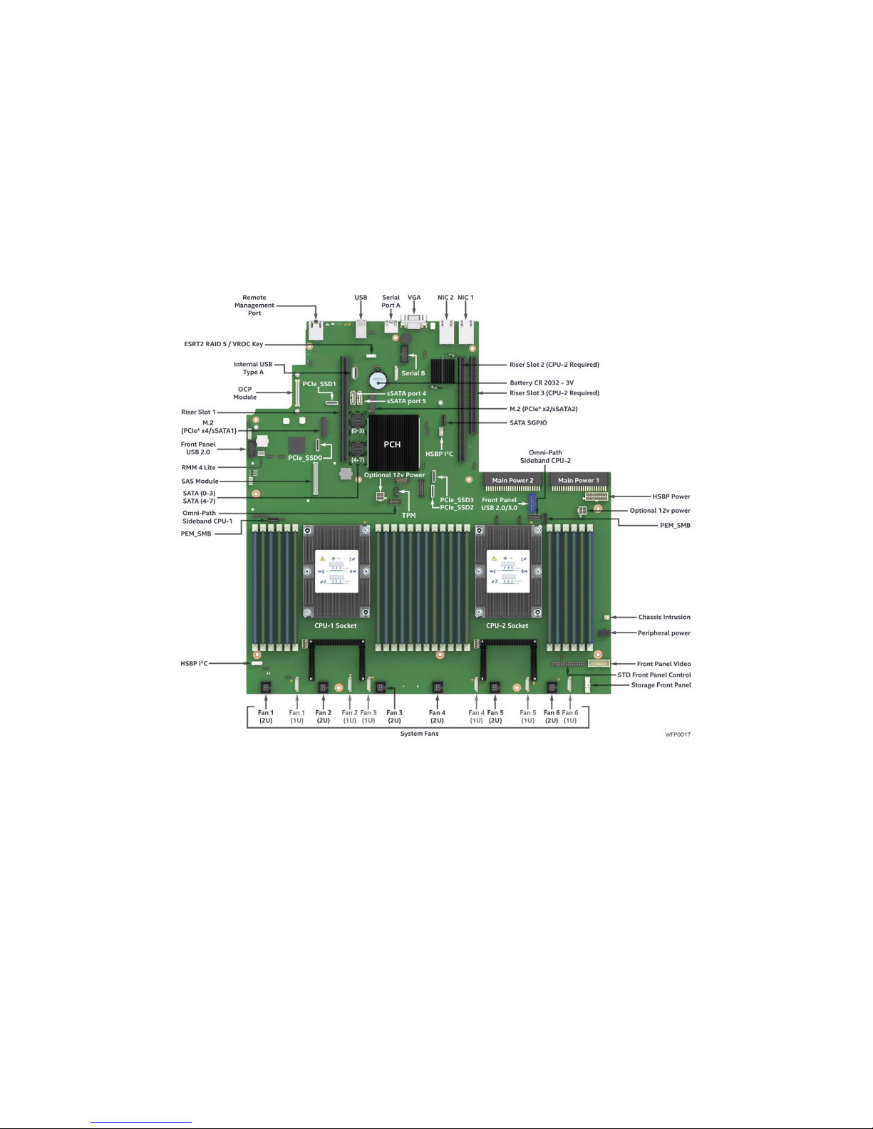
1.1 Intel Server Board S2600WF Product Family
Figure 1. Intel® Server Board S2600WF onboard features
Note: The illustration above provides an overview of available server board features. Some features may not be present on all available server
board options. See Table 4 for a complete list of features supported on a given server board option.
The Intel® Server Board S2600WF family consists of three server board options with features defined below.
Page 16

Intel® Server S2600WF Product Family Configuration Guide and Spares/Accessories List
16
Table 4. Server board product family features table
Intel Server Board
Product Code
Intel® Server Board S2600WFT Intel® Server Board S2600WF0 Intel® Server Board S2600WFQ
Processor Support
• Two LGA3647-0 (Socket P) processor sockets
• Support for one or two Intel
®
Xeon® processors
o Intel
®
Xeon® processor Scalable family only. Previous generation Intel® Xeon® processors are not supported
• Maximum supported Thermal Design Power (TDP) of up to 205W (board only)
Note: Intel Server Systems based on this server board family may support a lower maximum Thermal Design Power (TDP)
Memory
• 24 Total DIMM slots
o 12 DIMM slots per processor
o 6 Memory Channels / 2 DIMMs per Channel per processor
• Registered DDR4 (RDIMM), Load Reduced DDR4 (LRDIMM)
• Memory data transfer rates:
o DDR4 up to 2666 MT/s (Processor SKU Dependent)
DDR4 standard voltage of 1.2V
Intel® C62x Series
Chipset
Intel® C624 Chipset Intel® C624 Chipset
Intel® C628 Chipset
Intel® Quick Assist
Technology (QAT)
No No Yes
Intel® Omni-Path
Fabric Support
Yes Yes Yes
Onboard LAN
Dual Port RJ45 10GbE No No
Intel® OCP Module
Support
iPC = Intel Product
Code
• iPC X557T2OCPG1P5 – Dual Port 10Gb RJ45
• iPC X527DA2OCPG1P5 – Dual Port SFP+
• iPC I357T4OCPG1P5 – Quad Port 1Gb RJ45
• iPC X527DA4OCPG1P5 – Quad Port SFP+
• iPC X557T2OCPG1P5 – Dual Port 10Gb RJ45
• iPC X527DA2OCPG1P5 – Dual Port SFP+
• iPC I357T4OCPG1P5 – Quad Port 1Gb RJ45
• iPC X527DA4OCPG1P5 – Quad Port SFP+
• iPC X557T2OCPG1P5 – Dual Port 10Gb RJ45
• iPC X527DA2OCPG1P5 – Dual Port SFP+
Intel® Integrated SAS
Module Support
Yes Yes
Yes
Onboard PCIe* NVMe
Support
4 – OCuLink Connectors
Intel® VMD Support
Intel® RSTe VROC Support – Acc. Option
4 – OCuLink Connectors
Intel® VMD Support
Intel® RSTe VROC Support – Acc. Option
2 – OCuLink Connectors
Intel® VMD Support
Intel® RSTe VROC Support – Acc. Option
Page 17

Intel® Server S2600WF Product Family Configuration Guide and Spares/Accessories List
17
Intel Server Board
Product Code
Intel® Server Board S2600WFT Intel® Server Board S2600WF0 Intel® Server Board S2600WFQ
Onboard SATA
Support
• 12 x SATA 6Gbps ports (6Gb/s, 3 Gb/s and
1.5Gb/s transfer rates are supported)
o Two single port 7-pin SATA connectors
o Two M.2 connectors – SATA / PCIe*
o Two 4-port mini-SAS HD (SFF-8643)
connectors
• Embedded SATA Software RAID
o Intel® Rapid Storage RAID Technology
(RSTe) 5.0
o Intel® Embedded Server RAID
Technology 2 (ESRT2) 1.60 with
optional RAID 5 key support
• 12 x SATA 6Gbps ports (6Gb/s, 3 Gb/s and
1.5Gb/s transfer rates are supported)
o Two single port 7-pin SATA connectors
o Two M.2 connectors – SATA / PCIe*
o Two 4-port mini-SAS HD (SFF-8643)
connectors
• Embedded SATA Software RAID
o Intel® Rapid Storage RAID Technology
(RSTe) 5.0
o Intel® Embedded Server RAID Technology
2 (ESRT2) 1.60 with optional RAID 5 key
support
• 4 x SATA 6Gbps ports (6Gb/s, 3 Gb/s and
1.5Gb/s transfer rates are supported)
o Two single port 7-pin SATA connectors
o Two M.2 connectors – SATA / PCIe*
• Embedded SATA Software RAID
o Intel® Rapid Storage RAID Technology
(RSTe) 5.0
NOTE: The 4-port mini-SAS HD connectors
present on S2600WFQ boards are used to
support Intel® Quick Assist Technology (QAT)
only. No SATA ports are routed to these
connectors
Riser Card Support
Concurrent support for up to three riser cards
• Riser #1 – PCIe* 3.0 x24 (CPU1 x16, CPU2 x8) – 1, 2, and 3 slot riser card options available
• Riser #2 – PCIe* 3.0 x24 (CPU2 x24) – 1, 2, and 3 slot riser card options available
• Riser #3 (2U systems only) – PCIe* 3.0 (CPU 2 x12) – 2 slot riser card available (low profile add-in cards only)
Video
• Integrated 2D Video Controller
• 16MB of DDR4 Video Memory
• One DB-15 External Connector
• One 14-Pin Internal connector for optional Front Panel Video support
USB Support
• Three external USB 3.0 ports
• One internal Type-A USB 2.0 port
• One internal 20-pin connector for optional 2x USB 3.0 port Front Panel support
• One Internal 10-pin connector for optional 2x USB 2.0 port Front Panel support
Serial Port Support
• One external RJ-45 Serial-A port connector
• One internal DH-10 Serial-B port header for optional front or rear serial port support
Server Management
• Integrated Baseboard Management Controller, IPMI 2.0 compliant
• Support for Intel® Server Management Software
• Onboard dedicated RJ45 management port
• Support for Advanced Server Management features via an Intel® Remote Management Module 4 Lite Accessory Option (iPC – AXXRMM4LITE2)
TPM Security Support
• Intel® Trusted Platform Module 2.0 (Rest of World) – iPC- AXXTPMENC8 (Accessory Option)
• Intel® Trusted Platform Module 2.0 (China Version) – iPC- AXXTPMCHNE8 (Accessory Option)
System Fan Support
• Six System fans supported in two different connector formats hot swap (2U) and cabled (1U)
o Six 10-pin managed system fan headers (Sys_Fan 1-6) – Used for 1U system configuration
o
Six 6-pin hot swap capable managed system fan connectors (Sys_Fan 1-6) – Used for 2U system Configuration
Page 18
Intel® Server S2600WF Product Family Configuration Guide and Spares/Accessories List
18
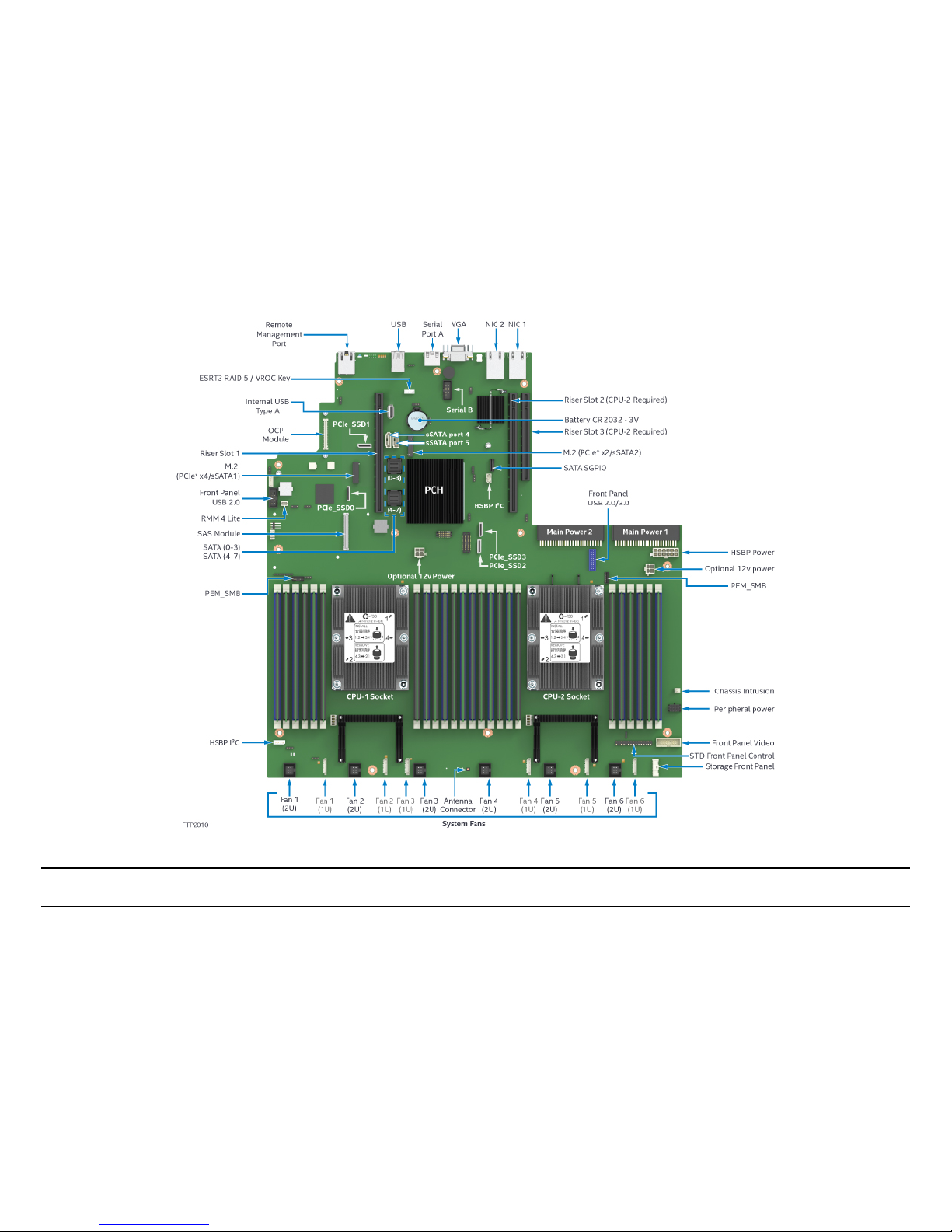
1.2 Intel Server Board S2600WFTF Product Family
Figure 2. Intel® Server Board S2600WFTF onboard features
Note: The illustration above provides an overview of available server board features. Some features may not be present on all available server
board options. See Table 5 for a complete list of features supported on a given server board option.
The Intel® Server Board S2600WFTF family consists of the server board with features defined below.
Page 19

Intel® Server S2600WF Product Family Configuration Guide and Spares/Accessories List
19
Table 5. Intel® Server Board S2600WFTF product family features table
Intel Server Board
Product Code
Intel® Server Board S2600WFTF
Processor Support
• Two LGA3647-0 (Socket P) processor sockets
• Support for one or two of the following Intel
®
Xeon® processors depending upon configuration:
o Intel® Xeon® Silver 4106H processor
o Intel® Xeon® Gold 6130H processor
o Intel® Xeon® Platinum 8160H processor
Note: Intel Server Systems based on this server board family may support a lower maximum Thermal Design Power (TDP)
Memory
• 24 Total DIMM slots
o 12 DIMM slots per processor
o 6 Memory Channels / 2 DIMMs per Channel per processor
• Registered DDR4 (RDIMM), Load Reduced DDR4 (LRDIMM)
• Memory data transfer rates:
o DDR4 up to 2666 MT/s (Processor SKU Dependent)
DDR4 standard voltage of 1.2V
Intel® C62x Series
Chipset
Intel® C624 Chipset
Intel® Platform
Firmware Resilience
Yes
Protect-in-Transit
Yes
Intel® Quick Assist
Technology (QAT)
No
Intel® Omni-Path
Fabric Support
No
Onboard LAN
Dual Port RJ45 10GbE
Intel® OCP Module
Support
iPC = Intel Product
Code
• iPC X557T2OCPG1P5 – Dual Port 10Gb RJ45
• iPC X527DA2OCPG1P5 – Dual Port SFP+
Intel® Integrated SAS
Module Support
Yes
Onboard PCIe* NVMe
Support
4 – OCuLink Connectors
Intel® VMD Support
Intel® RSTe VROC Support – Acc. Option
Page 20

Intel® Server S2600WF Product Family Configuration Guide and Spares/Accessories List
20
Intel Server Board
Product Code
Intel® Server Board S2600WFTF
Onboard SATA
Support
• 12 x SATA 6Gbps ports (6Gb/s, 3 Gb/s and 1.5Gb/s transfer rates are supported)
o Two single port 7-pin SATA connectors
o Two M.2 connectors – SATA / PCIe*
o Two 4-port mini-SAS HD (SFF-8643) connectors
• Embedded SATA Software RAID
o Intel® Rapid Storage RAID Technology (RSTe) 5.0
Intel® Embedded Server RAID Technology 2 (ESRT2) 1.60 with optional RAID 5 key support
Riser Card Support
Concurrent support for up to three riser cards
• Riser #1 – PCIe* 3.0 x24 (CPU1 x16, CPU2 x8) – 1, 2, and 3 slot riser card options available
• Riser #2 – PCIe* 3.0 x24 (CPU2 x24) – 1, 2, and 3 slot riser card options available
• Riser #3 (2U systems only) – PCIe* 3.0 (CPU 2 x12) – 2 slot riser card available (low profile add-in cards only)
Video
• Integrated 2D Video Controller
• 16MB of DDR4 Video Memory
• One DB-15 External Connector
•
One 14-Pin Internal connector for optional Front Panel Video support
USB Support
• Three external USB 3.0 ports
• One internal Type-A USB 2.0 port
• One internal 20-pin connector for optional 2x USB 3.0 port Front Panel support
• One Internal 10-pin connector for optional 2x USB 2.0 port Front Panel support
Serial Port Support
• One external RJ-45 Serial-A port connector
•
One internal DH-10 Serial-B port header for optional front or rear serial port support
Server Management
•
Integrated Baseboard Management Controller, IPMI 2.0 compliant
• Support for Intel® Server Management Software
• Onboard dedicated RJ45 management port
• Support for Advanced Server Management features via an Intel® Remote Management Module 4 Lite Accessory Option (iPC – AXXRMM4LITE2)
TPM Security Support
• Intel® Trusted Platform Module 2.0 (Rest of World) down
System Fan Support
• Six System fans supported in two different connector formats hot swap (2U) and cabled (1U)
o Six 10-pin managed system fan headers (Sys_Fan 1-6) – Used for 1U system configuration
o
Six 6-pin hot swap capable managed system fan connectors (Sys_Fan 1-6) – Used for 2U system Configuration
Antenna Support
RFID Near Field Antenna, I-PEX connector
Page 21
Intel® Server S2600WF Product Family Configuration Guide and Spares/Accessories List
21
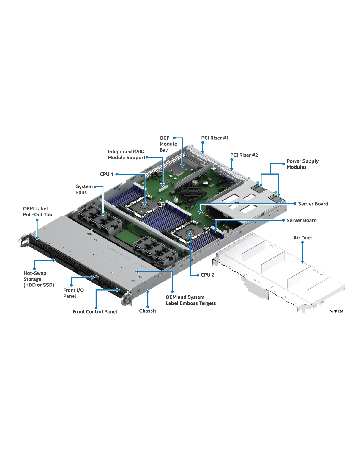
1.3 Intel Server System R1000WF Product Family
Figure 3. Intel® Server System R1000WF feature set identification
Page 22
Intel® Server S2600WF Product Family Configuration Guide and Spares/Accessories List
22
Figure 4. 1U, 3.5” x 4 drive configuration (Intel® Server System R1304xxx)
Figure 5. 1U, 2.5" x 8 drive configuration (Intel® Server System R1208WFxxx)
Where xxx defines the specific system model or product code.
Figure 6. 1U system back panel Figure 6. 1U system back panel
Page 23

Intel® Server S2600WF Product Family Configuration Guide and Spares/Accessories List
23
Table 6. Intel® Server System R1000WF product family features table
Chassis Type
1U Rack Mount Chassis
Server Board
Intel® Server Board S2600WF product family
Maximum Supported Processor Thermal
Design Power (TDP)
165 Watts
External I/O Connections
• DB-15 Video connectors
o Front and Back
• RJ-45 Serial Port A connector
• Dual RJ-45 Network Interface connectors – (S2600WFT based systems only)
• Dedicated RJ-45 server management NIC
• Three USB 3.0 connectors on back panel
•
Two USB 3.0 connectors on front panel
Internal I/O Connectors / Headers
• One Type-A USB 2.0 connector
•
One DH-10 Serial Port B connector
System Fans
• Six managed 40mm dual rotor system fans
• One power supply fan for each installed power supply module
Riser Card Support
Support for two riser cards:
• Riser #1 – PCIe* Gen3 x24
• Riser #2 – PCIe* Gen3 x24
With two riser cards installed, up to 2 possible add-in cards can be supported:
• One x16 PCIe* 3.0 Add-in card slot per riser card
•
2 Full Height / Half Length add-in cards via Risers #1 and #2
Power Supply Options
• The server system can have up to two power supply modules installed, providing support for the following power
configurations: 1+0, 1+1 Redundant Power, and 2+0 Combined Power
• Two power supply options:
o AC 1100W Platinum
o
DC 750W Gold
Storage Bay Options
• Hot Swap Backplane Options:
• Note: All available backplane options have support for SAS 3.0 (12 Gb/sec)
o 4 x 3.5” SAS/SATA backplane
o 8 x 2.5” combo backplane – SAS/SATA/NVMe
• Storage Bay Options:
o 4 x 3.5” SAS/SATA hot swap drive bays + front panel I/O
o
8 x 2.5” SAS/SATA/NVMe hot swap drive bays + front panel I/O
Supported Rack Mount Kit Accessory
Options
• A1UFULLRAIL – Tool-less rack mount rail kit – 780mm max travel length, 18kgs (39lbs.) max supported weight
• A1USHRTRAIL- 780mm max travel length, 18kgs (39lbs.) max supported weight
• AXXELVRAIL – Enhanced value rack mount rail kit - 424mm max travel length, 59kgs (130lbs.) max supported weight
• AXX2POSTBRCKT – Two post fixed mount bracket kit – Fixed mount brackets for 2-post racks
• AXX1U2UCMA – Cable Management Arm – (*supported with A1UFULLRAIL only)
Page 24

Intel® Server S2600WF Product Family Configuration Guide and Spares/Accessories List
24
1.4 Intel® Server System R2000WF Product Family
Figure 7. Intel® Server System R2000WF feature set identification
Page 25
Intel® Server S2600WF Product Family Configuration Guide and Spares/Accessories List
25
Figure 8. 2U, No drive bays, chassis only building block (Intel® Server Chassis R2000WFxxx)
.
Figure 9. 2U, 3.5" x 8 drive configuration (Intel® Server System R2308WFxxx)
Figure 10. 2U, 3.5" x 12 drive configuration (Intel® Server System R2312WFxxx – storage configuration)
Where xxxx defines the specific system model or product code.
Page 26
Intel® Server S2600WF Product Family Configuration Guide and Spares/Accessories List
26
Figure 11. 2U, 2.5" x 8 drive configuration (Intel® Server System R2208WFxxx)
Figure 12. 2U, 2.5" x 16 drive configuration (Intel® Server System R2208WFxxx + 8 drive accessory kit)
Figure 13. 2U, 2.5" x 24 drive configuration (Intel® Server System R2224WFxxx – storage configuration)
Page 27
Intel® Server S2600WF Product Family Configuration Guide and Spares/Accessories List
27
Figure 14. 2U System back panel with optional 2 x 2.5” hot swap drive bay
Where xxx defines the specific system model or product code.
Table 7. Intel® Server System R2000WF product family features table
Feature
Description
Chassis Type
2U Rack Mount Chassis
Server Board
Intel® Server Board S2600WF product family
Maximum Supported Processor Thermal
Design Power (TDP)
Up to 140 Watt on R2312WFxxx
Up to 150 Watt on R2224WFxxx
Up to 205 Watt processors only supported on R2208WFxxx, R2208WFxxx + 8 Drive Accessory Kit, and R2308WFxxx
configurations
External I/O Connections
• DB-15 Video connectors
• Front and Back (non-storage system configurations only)**
• RJ-45 Serial Port A connector
• Dual RJ-45 Network Interface connectors – (S2600WFT based systems only)
• Dedicated RJ-45 server management NIC
• Three USB 3.0 connectors on back panel
• Two USB 3.0 connectors on front panel (non-storage system configurations only)**
•
One USB 2.0 connector on rack handle (storage configurations only)**
Internal I/O Connectors / Headers
•
One Type-A USB 2.0 connector
•
One DH-10 Serial Port B connector
System Fans
•
Six managed 60mm hot swap capable system fans
•
Integrated fans included with each installed power supply module
Riser Card Support
Support for three riser cards:
• Riser #1 – PCIe* 3.0 x24 - up to 3 PCIe slots
• Riser #2 – PCIe* 3.0 x24 - up to 3 PCIe slots
• Riser #3 – PCIe* 3.0 x16 – up to 2 PCIe slots – Low profile cards only (optional)
With three riser cards installed, up to 8 possible add-in cards can be supported:
• 4 Full Height / Half Length + 2 Full Height / Half Length add-in cards via Risers #1 and #2
•
2 Low profile add in cards via riser #3 (option)
Page 28

Intel® Server S2600WF Product Family Configuration Guide and Spares/Accessories List
28
Feature
Description
Power Supply Options
The server system can have up to two power supply modules installed, providing support for the following power
configurations: 1+0, 1+1 Redundant Power, and 2+0 Combined Power
Three power supply options:
• AC 1100W Platinum
• AC 1300W Titanium
• DC 750W Gold
Storage Bay Options
Hot Swap Backplane Options:
Note: All available backplane options have support for SAS 3.0 (12 Gb/sec)
• 8 x 3.5” SAS/ SATA
• 8 x 2.5” combo backplane – SAS/SATA/NVMe
• 8 x 2.5” Dual Port SAS
• 12 x 3.5” SAS/ SATA (supports up to 2 NVMe drives)
Storage Bay Options:
• 8 x 3.5” SAS/SATA hot swap drive bays + Standard front panel
• 12 x 3.5” SAS/SATA hot swap drive bays (supports up to 2NVMe drives) + Storage Front Panel
• 8 x 2.5” SAS/SATA/NVMe hot swap drive bays + Standard front panel
• 16 (8+8 acc) x 2.5” SAS/SATA/NVMe hot swap drive bays + Standard front panel
• 24 x 2.5” SAS/SATA/NVMe swap drive bays + Storage front panel
• 2 x 2.5” SATA SSD Back of Chassis Hot Swap Drive Bays (accessory Option)
• 2 x internal fixed mount 2.5” SSDs (all SYSTEM MODELs)
Supported Rack Mount Kit Accessory
Options
• AXXELVRAIL – Enhanced value rack mount rail kit - 424mm max travel length, 59kgs (130lbs.) max supported weight
• AXXFULLRAIL- 2U Premium rail with CMA support – 800mm max travel length, 45kgs (99lbs.) max supported weight
• AXXSHRTRAIL - 2U Premium rail without CMA support - 788mm max travel length, 45kgs (99lbs.) max supported weight
• AXX2POSTBRCKT – Two post fixed mount bracket kit
• AXXCMA2– Cable Management Arm – (*supported with AXXFULLRAIL only)
** Storage System Configurations include the following: R2312WFxxxx and R2224WFxxxx
Non-Storage System Configurations include: R2308WFxxxx, R2208WFxxxx, and R2208WFxxxx + 8 Drive Accessory Kit
Page 29

Intel® Server S2600WF Product Family Configuration Guide and Spares/Accessories List
29
1.5 Available Server Board, Chassis, and System SKU Summary
The following tables provide an overview of available Intel product codes for building blocks and systems within the Intel® S2600WF product
family. Each line item identifies key features supported in the shipping Intel SKU. Additional order code information and full product descriptions
for each option are provided in later sections. Terms used in the tables:
na – Not Applicable
opt – Accessory option sold separately
yes – Option included
KDK – Knock Down Kit – Intel term for chassis only product
BIK – Server Board in KDK – Intel term for integrated (L6) system product
L3 – Server System Building Block - Chassis components only. No server board installed
L6 – Integrated system: Chassis + Server Board, with no processors, memory, or storage devices
L9 - Integrated system: Chassis + Server Board, with processors and memory, no storage devices
Table 8. Server board product family summary
Intel Product
Code
# of
CPU
sockets
# of
DIMM
Slots
# of
Riser
Slots
Onboard
10GbE
LAN ports
Onboard
SATA ports
(6 Gb)
Onboard
NVMe
Ports
Intel® SAS
RAID Module
support
Intel® OCP
Module
Support
Onboard
Video
QAT Support
(Quick Assist
Technology)
Onboard System
Fan Support
Server Board
only
S2600WF0 2 24 3 0 12 4 Yes Yes Yes No Up to 6
S2600WFT 2 24 3 2 12 4 Yes Yes Yes No Up to 6
S2600WFQ 2 24 3 0 4 2 Yes Yes Yes Yes Up to 6
Server System Building Block – Server Board Only
Table 9. Server chassis (KDK) product family summary
Intel Product
Code
Integration
Level
Chassis
Form Factor
Server
Board
Option
Drive
Form
Factor
# of
Drives
(front)
2.5”
NVMe
Support
# of
SSD
Drives
(rear)
# of PCIe*
Add-in
Card Slots
3
rd
Riser
Power Supply
Modules
Rails
SAS
RAID
SAS
Expander
Chassis Only
R1304WFXXX L3 1U opt 3.5”/2.5” 4 No na
opt
up to 2
na opt opt opt na
R2000WFXXX L3 2U opt opt opt opt opt
opt
Up to 8
opt opt opt opt opt
L3 = Server System Building Block - Chassis components only. No server board installed
Page 30

Intel® Server S2600WF Product Family Configuration Guide and Spares/Accessories List
30
R2000WF Chassis can support all available 8x2.5” drive bay accessory options
Table 10. Server system (BIK) product family summary
Intel
Product
Code
Integration
Level
Chassis
Form
Factor
Server
Board
Option
Drive
Form
Factor
# of
Drives
(front)
2.5”
NVMe
Support
# of
SSD
Drives
(rear)
# of
PCIe*
Add-in
Card
Slots
3rd
Riser
Power
Supply
Modules
Rails
SAS
RAID
SAS
Expander
Memory Processor
L6 System
R1304WFT
YS
L6 1U
S2600
WFT
3.5”/2.
5”
4 No na 2 na
1x
1100W
AC
opt opt na
add
add
R1304WF0
YS
L6 1U
S2600
WF0
3.5”/2.
5”
4 No na 2 na
1x
1100W
AC
opt opt na
add
add
R1208WFT
YS
L6 1U
S2600
WFT
2.5” 8 Up to 8 na 2 na
1x
1100W
AC
opt opt na
add
add
R2308WFT
ZS
L6 2U
S2600
WFT
3.5”/2.
5”
8 No opt 8 Yes
1x
1300W
AC
opt opt na
add
add
R2312WF0
NP
L6 2U
S2600
WF0
3.5”/2.
5”
12 Up to 2 opt 8 Yes opt opt opt opt
add
add
R2312WFT
ZS
L6 2U
S2600
WFT
3.5”/2.
5”
12 Up to 2 opt 8 Yes
1x
1300W
AC
opt opt opt
add
add
R2312WFQ
ZS
L6 2U
S2600
WFTQ
3.5”/2.
5”
12 Up to 2 opt 8 Yes
1x
1300W
AC
opt opt opt
add
add
R2208WFT
ZS
L6 2U
S2600
WFT
2.5” 8 Up to 8 opt 8 Yes
1x
1300W
AC
opt opt
opt
add
add
R2208WF0
ZS
L6 2U
S2600
WF0
2.5” 8 Up to 8 opt 8 Yes
1x
1300W
AC
opt opt
opt
add
add
R2208WFQ
ZS
L6 2U
S2600
WFQ
2.5” 8 Up to 8 opt 8 Yes
1x
1300W
AC
opt opt
opt
add
add
R2224WFT
ZS
L6 2U
S2600
WFT
2.5” 24 Up to 24 opt 8 Yes
1x
1300W
AC
opt opt opt add add
Page 31

Intel® Server S2600WF Product Family Configuration Guide and Spares/Accessories List
31
Intel
Product
Code
Integration
Level
Chassis
Form
Factor
Server
Board
Option
Drive
Form
Factor
# of
Drives
(front)
2.5”
NVMe
Support
# of
SSD
Drives
(rear)
# of
PCIe*
Add-in
Card
Slots
3rd
Riser
Power
Supply
Modules
Rails
SAS
RAID
SAS
Expander
Memory Processor
R2224WFQ
ZS
L6 2U
S2600
WFQ
2.5” 24 Up to 24 opt 8 Yes
1x
1300W
AC
opt opt opt add add
L9 System
LFRB2208
WFTF801
L9
2U
S2600
WFTF
2.5” 8 Up to 8
opt 8 Yes
2x
1300W
opt opt opt
Yes
Yes
LFRB2208
WFTF601
L9
2U
S2600
WFTF
2.5” 8 Up to 8
opt 8 Yes
2x
1300W
opt opt opt
Yes
Yes
LFRB2208
WFTF401
L9
2U
S2600
WFTF
2.5” 8 Up to 8
opt 8 Yes
2x
1300W
opt opt opt
Yes
Yes
LFRB2312
WFTF801
L9
2U
S2600
WFTF
3.5”/2.
5”
12
Up to 2
opt 8 Yes
2x
1300W
opt opt opt
Yes
Yes
LFRB2312
WFTF601
L9
2U
S2600
WFTF
3.5”/2.
5”
12
Up to 2
opt 8 Yes
2x
1300W
opt opt opt
Yes
Yes
LFRB2312
WFTF401
L9
2U
S2600
WFTF
3.5”/2.
5”
12
Up to 2
opt 8 Yes
2x
1300W
opt opt opt
Yes
Yes
L6 = Integrated chassis with Server Board installed. No CPU, No Memory, No Storage Devices, no accessory options included
L9 = Integrated chassis with Server Board, CPUs and memory installed. No Storage Devices, some accessory options included, see Server System Configurations in Chapter 3 for
product code specific details. The L9 systems listed are part of the Intel® Data Center Block with Firmware Resilience product.
All front drive bays are 12Gb SAS capable
Page 32

Intel® Server S2600WF Product Family Configuration Guide and Spares/Accessories List
32
1.6 Intel® Server System R2000WFTF Product Family
Figure 15. Intel® Server System R2000WFTF feature set identification
Page 33

Intel® Server S2600WF Product Family Configuration Guide and Spares/Accessories List
33
Figure 16. 2U, 2.5" x 8 drive configuration (Intel® Server System LFRB2208WFTFxxx)
Figure 17. 2U, 3.5" x 12 drive configuration (Intel® Server System LFRB2312WFTFxxx – storage configuration)
Figure 18. 2U System Back Panel with Optional 2 x 2.5” Hot Swap Drive Bay
Where xxx defines the specific system model or product code.
Page 34

Intel® Server S2600WF Product Family Configuration Guide and Spares/Accessories List
34
Table 11. Intel® Server System R2000WFTF product family features table
Feature
Description
Chassis Type
2U Rack Mount Chassis
Server Board
Intel® Server Board S2600WFTF product family
Maximum Supported Processor Thermal
Design Power (TDP)
Up to 150W
External I/O Connections
• DB-15 Video connectors
• Front and Back (non-storage system configurations only)**
• RJ-45 Serial Port A connector
• Dual RJ-45 Network Interface connectors – (S2600WFT based systems only)
• Dedicated RJ-45 server management NIC
• Three USB 3.0 connectors on back panel
• Two USB 3.0 connectors on front panel (non-storage system configurations only)**
•
One USB 2.0 connector on rack handle (storage configurations only)**
Internal I/O Connectors / Headers
• One Type-A USB 2.0 connector
•
One DH-10 Serial Port B connector
System Fans
• Six managed 60mm hot swap capable system fans
•
Integrated fans included with each installed power supply module
Riser Card Support
Support for three riser cards:
• Riser #1 – PCIe* 3.0 x24 - up to 3 PCIe slots
• Riser #2 – PCIe* 3.0 x24 - up to 3 PCIe slots
• Riser #3 – PCIe* 3.0 x16 – up to 2 PCIe slots – Low profile cards only (optional)
With three riser cards installed, up to 8 possible add-in cards can be supported:
• 4 Full Height / Half Length + 2 Full Height / Half Length add-in cards via Risers #1 and #2
•
2 Low profile add in cards via riser #3 (option)
Power Supply Options
Two power supply modules installed, providing support for the following power configurations: 1+0, 1+1 Redundant Power, and
2+0 Combined Power
Power supply options:
•
AC 1300W Titanium
Remote Management
Intel® Remote Management Module 4 Lite Activation Key
Storage Bay Options
Hot Swap Backplane Options:
Note: All available backplane options have support for SAS 3.0 (12 Gb/sec)
• 8 x 2.5” combo backplane – SAS/SATA/NVMe
• 8 x 2.5” Dual Port SAS
• 12 x 3.5” SAS/ SATA (supports up to 2 NVMe drives)
Storage Bay Options:
• 12 x 3.5” SAS/SATA hot swap drive bays (supports up to 2NVMe drives) + Storage Front Panel
• 8 x 2.5” SAS/SATA/NVMe hot swap drive bays + PFR front panel
• 16 (8+8 acc) x 2.5” SAS/SATA/NVMe hot swap drive bays + PFR front panel
• 2 x 2.5” SATA SSD Back of Chassis Hot Swap Drive Bays (accessory Option)
•
2 x internal fixed mount 2.5” SSDs (all SYSTEM MODELs)
Page 35

Intel® Server S2600WF Product Family Configuration Guide and Spares/Accessories List
35
Feature
Description
Supported Rack Mount Kit Accessory
Options
• AXXELVRAIL – Enhanced value rack mount rail kit - 424mm max travel length, 59kgs (130lbs.) max supported weight
• AXXFULLRAIL- 2U Premium rail with CMA support – 800mm max travel length, 45kgs (99lbs.) max supported weight
• AXXSHRTRAIL - 2U Premium rail without CMA support - 788mm max travel length, 45kgs (99lbs.) max supported weight
• AXX2POSTBRCKT – Two post fixed mount bracket kit
•
AXXCMA2– Cable Management Arm – (*supported with AXXFULLRAIL only)
Page 36

Intel® Server S2600WF Product Family Configuration Guide and Spares/Accessories List
36
2. Server Building Block Options
Server building blocks are offered to provide the option of picking and choosing from available Intel server components to create a custom system
configuration from the chassis up. Each building block component and optional accessory is purchased separately and assembled by a system
integrator. At a minimum, building up a base functional server system using building blocks will require the following:
• 1U or 2U Intel Server Chassis – Intel® Server Chassis R1000WF or R2000WF
• Intel® Server Board S2600WF product family option
• Power Supply module(s)
• SATA / NVMe data cables
• Power cord(s)
• Rack mount kit – Rails or fixed mount
• Processor
• Memory
• Storage Devices
Also offered are preconfigured L9 systems which only require the addition of power cords and storage devices to become a functional server. L9
systems are a part of the Intel® Data Center Block with Firmware Resilience product.
Optional Intel accessories that can be added include the following: See Chapter 5 for available options.
• Riser cards options
• Intel® SAS / SAS RAID support – PCIe* add-in card or module + Appropriate SAS Data cable(s)
Intel® Server Chassis R1000WF
Intel® Server Chassis R2000WF
Intel® Server Board S2600WF
Power Supply Modules
PCIe Riser Cards
Page 37

Intel® Server S2600WF Product Family Configuration Guide and Spares/Accessories List
37
• Intel® OCP Module - to add additional features without losing a PCIe add-in slot
• Intel® Remote Management Module Lite key – to add advanced server management features
2.1 Intel® Server Board S2600WF Product Family Options
Table 12. Intel® Server Board S2600WF product family options
Intel Product Code
(iPC)
Order Information
Product Description Product Type
iPC – S2600WFT
MM# - 952641
UPC - 00735858344463
EAN - 5032037105255
MOQ - 1
Packaged Gross Weight
3.3 Kgs, 7.3Lbs
Un-packaged Net Weight
1.7 Kgs, 4.2Lbs
Intel® Server Board S2600WFT
See Table 4 for full Feature Set
Unique board features include:
• Intel® C624 Chipset
• Onboard Dual Port RJ45 10GbE LAN
• 4 – Onboard PCIe NVMe OCuLink Connectors
• 12 x SATA 6Gbps ports
Box includes: one server board
Note: All necessary mounting hardware, cabling, and shielding will ship with the Intel chassis
and optional accessory kits.
Server Board Only
• Building block
option
• Spare FRU
iPC – S2600WF0
MM# - 952644
UPC - 00735858344470
EAN - 5032037105262
MOQ - 1
Packaged Gross Weight
3.3 Kgs, 7.3Lbs
Un-packaged Net Weight
1.7 Kgs, 4.2Lbs
Intel® Server Board S2600WF0
See Table 4 for full Feature Set
Unique board features include:
• Intel® C624 Chipset
• No Onboard LAN support
• 4 – Onboard PCIe NVMe OCuLink Connectors
• 12 x SATA 6Gbps ports
Box includes: one server board
Note: All necessary mounting hardware, cabling, and shielding will ship with the Intel chassis
and optional accessory kits.
Server Board Only
• Building block
option
• Spare FRU
Page 38

Intel® Server S2600WF Product Family Configuration Guide and Spares/Accessories List
38
iPC – S2600WFQ
MM# - 952645
UPC - 00735858344456
EAN - 5032037105248
MOQ - 1
Packaged Gross Weight
3.3 Kgs, 7.3Lbs
Un-packaged Net Weight
1.7 Kgs, 4.2Lbs
Intel® Server Board S2600WFQ
See Table 4 for full Feature Set
Unique board features include:
• Intel® C628 Chipset
• Support for QAT
• No Onboard LAN support
• 2– Onboard PCIe NVMe OCuLink Connectors
• 4 x SATA 6Gbps ports
Box includes: one server board, one QAT cable.
Note: All necessary mounting hardware, cabling, and shielding will ship with the Intel chassis
and optional accessory kits. OCuLink Connectors from CPU1 can be used for NVMe drives.
OCuLink Connectors from CPU2 are used for Intel® Quick Assist Technology (QAT) link and
will not work for NVMe drives.
Server Board Only
• Building block
option
• Spare FRU
Page 39

Intel® Server S2600WF Product Family Configuration Guide and Spares/Accessories List
39
2.2 Intel® Server Chassis Product Family Options
The product tables found in this section provide order code information and detailed descriptions for each available 1U and 2U Intel server chassis
building block option. The lower sections of each table identify:
• The ship along components of the specified chassis product code – (product BOM)
• Required Items – Hardware required to be installed to the base system to achieve basic functionality using the default system feature set.
• Optional Accessories – Some of the available accessories which can be installed to enhance the basic feature set of the server board / chassis.
Additional accessories can be found in Chapter 5
Note:
• Each required item and optional accessory is sold separately from the specified Intel server building block.
• Items identified as iPC (Intel Product Code), are an orderable building block option, accessory or spare FRU.
In an effort to provide the complete product bill of materials, the ship along components list in each product table will include items identified by
description and by iPN (Intel Part Number). The iPN information is provided for reference only. These components are not orderable as a spare or
accessory.
Intel® Server Chassis R1000WF
Intel® Server Chassis R2000WF
Page 40

Intel® Server S2600WF Product Family Configuration Guide and Spares/Accessories List
40
Intel Product Code (iPC): R1304WFXXX
1U – 4 x 3.5” HDD or 4 x 2.5” SSD SATA/SSD front mount
drives
Order Code Information:
MM# - 952622
UPC - 00735858344722
EAN - 5032037105439
MOQ - 1
Product Type: Chassis Only
Chassis Form Factor: 1U rack mount
Chassis dimensions: L=712mm, W=439mm, H=43.2mm
Packaged Gross Weight: 19 Kgs, 41.9 Lbs
Un-packaged Net Weight: 10.3 Kgs, 22.7 Lbs
Outer Box Dimensions: L=983mm, W=577mm, H=260mm
Intel® Server Chassis Product Definition and Configuration Requirements
Intel product code R1304WFXXX includes the following
components:
(1) – 1U Chassis with Quick Reference Label affixed to top cover
(4) – 3.5” Hot-swap drive bays with drive carriers and drive blanks
• includes (1) 12 Gb SAS backplane – iPC FR1304S3HSBP
• includes (4) 3.5” hot swap drive tool less carriers – iPC
FXX35HSCAR2
(1) – Pre-installed Standard Control Panel assembly
• (board only – iPC FXXFPANEL2)
• 260mm FP Cable iPN J25698-xxx
(1) – Pre-installed Front I/O Panel assembly (1 x VGA and 2 x USB)
• 620mm USB 3.0 cable – iPN H76899-xxx
• 400mm Video cable – iPN H62114-xxx
(1) – Server board to backplane 150mm I2C cable – iPN H91171-xxx
(1) – 850mm MiniSAS HD cable – iPC AXXCBL850HDHRT
(1) – 350mm Backplane power cable – iPN H82100-xxx
(1) – Air duct – iPN H90054-xxx
(6) – Dual rotor system fans – iPC FR1UFAN10PW
(2) – CPU heat sinks, 39 fin passive – iPN J39509-xxx
(2) – CPU heat sink “No CPU” label inserts – iPN J16115-xxx
(2) – Standard CPU Carriers – iPN H72851-xxx
(2) – 1 slot PCIe x16 Riser Card – iPN H88399-xxx
(8) – DIMM slot blanks – iPN G75158-xxx
(1) – Chassis Stiffener Bar – iPN J16623-xxx
(1) – Power Supply Bay blank insert
(2) – AC Power Cord retention strap assembly – iPN H23961-00x
Server board and riser card mounting screws
Spares for each screw type included
Required Items – Sold Separately:
Intel® Server Board S2600WF (choose one)
• iPC S2600WFT
• iPC S2600WF0
• iPC S2600WFQ
Power supply module(s) – (Choose one type) two
common modules required for redundancy
• iPC AXX1100PCRPS – 1100W AC Power Supply
module
• iPC AXX750DCCRPS – 750 W DC Power Supply
Module
Power Cord(s) – See Chapter 2.3
Rack Mount Kit – See Chapter 5.8
1 or 2 Intel® Xeon® Processor Scalable family
ECC DDR4 memory (RDIMM or LRDIMM)
•
Optional Intel Accessories – Sold Separately:
• Intel® OCP Module – See Chapter 5.5 for options
• Intel® SAS RAID Card / Module – See Chapter 5.6
for options
• SAS/SATA Data cables – Cable selection is
dependent on desired storage option. See Chapter
4 for available cable options
• iPC AXXRMM4LITE2 – Intel® Remote Management
Module Lite “RoHS free. For advanced
management features
• Storage Drives
See Chapter 5 for all available accessory options.
Page 41

Intel® Server S2600WF Product Family Configuration Guide and Spares/Accessories List
41
Intel Product Code (iPC): R2000WFXXX
2U – No front mount drives
Order Code Information:
MM# - 952623
UPC - 00735858344746
EAN - 5032037105453
MOQ - 1
Product Type: Chassis only
Chassis Form Factor: 2U rack mount
Chassis dimensions: L=712mm, W=439mm, H=89mm
Packaged Gross Weight: 19 Kgs, 41.9 Lbs
Un-packaged Net Weight: 13.3 Kgs, 29.3 Lbs
Outer Box Dimensions: L=983mm, W=577mm, H=260mm
Intel® Server Chassis Product Definition and Configuration Requirements
Intel product code R2000WFXXX includes the following
components:
(1) – 2U Chassis with Quick Reference Label affixed to top
cover
(1) – Standard control panel assembly (installed)
• board only – iPC FXXFPANEL2
• 300mm FP Cable – iPN H34381-xxx
(1) – Front I/O Panel assembly (VGA+2x USB 3.0) installed
• 620mm USB 3.0 cable iPN H76899-xxx
• 400mm video cable iPN H62114-xxx
(1) – Standard 2U Air duct iPN H90554-xxx
(6) – 60mm Hot swap system fan – iPC FR2UFAN60HSW
(2) – CPU heat sink – iPC H38569-xxx
(2) – CPU heat sink “No CPU” label insert – iPN J16115-xx
(2) – Standard CPU Carrier – iPN H72851-xxx
(1) – 3x RMFBU Mounting Bracket – iPN H18238-00x
(16) – DIMM slot blank – iPN G75158-xxx
(1) – 175mm I2C cable – iPN H91172-xxx
(1) – 250mm I2C cable – iPN H91166-xxx
(1) – 400/525/600mm HSBP Pwr Cable – iPN H82108-xxx
(1) – Internal fixed mount 250mm SSD drive power cable
- iPN J29245-xxx
(2) – Riser Card mounting brackets supporting up to 3
riser cards (riser cards sold separately – see Chapter
5.2)
(1) – Power supply bay blank insert
(2) – AC Power Cord retention strap assembly – iPN
H23961-00x
Server Board and Riser Card mounting screws
Spares for each screw type included
Required Items – Sold Separately:
• Intel® Server Board S2600WF (choose
one)
• iPC S2600WFT
• iPC S2600WFO
• iPC S2600WFQ
Power supply module(s) – (Choose one
type) two common modules required for
redundancy
• iPC AXX1300TCRPS – 1300W AC Power
Supply module
• iPC AXX1100PCRPS – 1100W AC Power
Supply module
• iPC AXX750DCCRPS – 750 W DC Power
Supply Module
Power Cord(s) – See Chapter 2.3
Rack Mount Kit – See Chapter 5.8
1 or 2 Intel® Xeon® Processor Scalable
family
ECC DDR4 memory (RDIMM or LRDIMM)
Optional Intel Accessories – Sold Separately
Front storage bay option
• Up to three 8 x 2.5” drive bay modules can be installed:
o iPC A2U8X25S3PHS– SAS/SATA/NVMe Combo
o iPC A2U8X25S3DPDK2 – Dual port SAS
• iPC A2U8X35S3HSDK1 – 8 x 3.5” drive bay module
Note: Re-uses control panel and front I/O panel. Includes
SAS/SATA data cables and peripheral power cable
Rear Storage Bay Option
o iPC A2UREARHSDK2 – Up to (2) hot swap SATA SSDs
Riser Cards – Up to three riser cards can be installed concurrently
• Risers Slots #1 and #2 – Available riser cards include:
o iPC A2UL8RISER2 – (3) x8 PCIe* 3.0 slots
o iPC A2UL16RISER2 – (1) x16 PCIe* slot + (1) x8 PCIe* slot
• Riser Slot #3 – Available riser cards include:
o iPC A2UX8X4RISER – (1) Low profile x8 PCIe* 3.0 slot + (1)
LP x8 PCIe* 2.0 slot
• SAS/SATA/NVMe Data cables – Cable selection is dependent on
desired storage option. See Chapter 4 for available cable options
• Intel® SAS RAID Card / Module – See Section 5.5 for options
• Intel SAS Expander Options – See Chapters 4.6.2 and 4.7.4
• Intel® OCP Module – See Chapter 5.6 for options
• iPC AXXRMM4LITE2 – Intel® Remote Management Module Lite,
“RoHS free”, key for advanced management features
See Chapter 6 for all available accessory options.
Page 42

Intel® Server S2600WF Product Family Configuration Guide and Spares/Accessories List
42
2.3 Intel Power Supply Modules and Power Cords
Intel Product Code Order Information Product Description Product Type
iPC – AXX1100PCRPS
MM# – 936183
UPC – 00735858287920
EAN – 5032037067478
MOQ - 1
1100W AC CRPS 80+ Platinum efficiency power supply module
Power cord sold separately
• 1U / 2U Building Block Option
• 1U / 2U Accessory Kit
• 1U / 2U Spare FRU
iPC – AXX1300TCRPS
MM# – 956542
UPC – 00735858345705
EAN – 5032037106191
MOQ - 1
1300W AC CRPS 80+ Titanium efficiency power supply module
Power cord sold separately
• 2U Building Block Option
• 2U Accessory Kit
• 2U Spare FRU
iPC – AXX750DCCRPS
MM# – 927253
UPC –00735858260862
EAN –5032037051354
MOQ - 1
750W -48v DC (Direct current) CRPS 80+ Gold efficiency power
supply module
Kit Includes:
(1) power supply
(1) O-ring terminal adapter.
Power cable sold separately
• 1U / 2U Building Block Option
• 1U / 2U Accessory Kit
• 1U / 2U Spare FRU
iPC – AXXDCCRPSCBL
MM – 922062
UPC – 00735858247993
EAN – 5032037042871
MOQ – 1
4000mm (13ft) DC power cable
Connects directly to power supply instead of O-ring terminals adapter
*Optional power cord for DC input Power Supplies
• 1U / 2U Accessory Kit
• 1U /2U Spare FRU
iPC – FPWRCABLENA
MM# – 879287
UPC – 00735858181129
EAN – 5032037015738
MOQ – 1
1500mm (59in) North American Power Cord
• 1U / 2U Accessory Kit
• 1U / 2U Spare FRU
Page 43

Intel® Server S2600WF Product Family Configuration Guide and Spares/Accessories List
43
3. Server System Configuration
The Intel® Server S2600WF product family includes several integrated server system options that include a 1U or 2U Chassis with different hot swap
drive bay configurations, a specific server board, power supply module, and riser cards. At a minimum, building up a functional server from one of
these options will require the following:
• Rack mount kit – Rails or fixed mount
• Power Cord(s)
•
Processor(s)
•
Memory
•
Storage Drives
Also offered are preconfigured L9 systems which only require the addition of power cords and storage devices to become a functional server. L9
systems are a part of the Intel® Data Center Block with Firmware Resilience product.
Optional Intel accessories that can be added include the following:
• 2
nd
power supply module to add power redundancy
• Intel® SAS / SAS RAID support – PCIe* add-in card or module + Appropriate SAS Data cable(s)
• Intel® RAID Maintenance Free Backup (RMFBU) – Intel SAS RAID Card backup accessory
• Intel® OCP Module - to add additional features without losing a PCIe add-in slot
Intel® Server System
R1000WF Product Family
Intel® Server System
R2000WF Product Family
*R1208WFxxxx Shown
*R2312WFxxxx shown
Page 44

Intel® Server S2600WF Product Family Configuration Guide and Spares/Accessories List
44
• Intel® Remote Management Module Lite key – to add advanced server management features
See Chapter 5 for a full list of available options.
3.1 Intel® Server System R1000WF Product Family SKUs – (1U Rack Mount System)
The product tables found in this section provide order code information and detailed descriptions for the specified L6 integrated 1U Intel server
system. The lower sections of each table identify:
• The ship along components of the specified system product code – (product BOM)
• Required Items – Hardware required to be installed to the base system to achieve basic functionality using the default system feature set
• Optional Accessories – Some of the available accessories which can be installed to enhance the basic feature set of the server board /
chassis. A full list of accessory options can be found in Chapter 5
NOTES:
• Each required item and optional accessory are sold separately from the specified Intel L6 server system
• Items identified as iPC (Intel Product Code), are an orderable building block option, accessory or spare FRU
• In an effort to provide the complete product bill of materials, the ship along components listed in each product table will include items
identified by description and by iPN (Intel Part Number). The iPN information is provided for reference only. These components are not
orderable as a spare or accessory.
• L6 – Integrated system: Chassis + Server Board, with no processors, memory, or storage devices.
• L9 - Integrated system: Chassis + Server Board, with processors and memory, no storage devices.
Figure 19. Intel® Server System R1000WF Product Family
*R1208WFxxxx shown
Page 45

Intel® Server S2600WF Product Family Configuration Guide and Spares/Accessories List
45
Intel Product Code (iPC): R1304WF0YS
1U – Intel® Server Board S2600WF0, 4 x 3.5” HDD or 4 x 2.5” SSD
SAS/SATA front mount drives
Order Code Information:
MM# - 952626
UPC – 00735858344715
EAN – 5032037105422
MOQ – 1
Product Type: L6 Integrated System
Chassis Form Factor: 1U rack mount
Chassis dimensions: L=712mm, W=439mm, H=43.2mm
Packaged Gross Weight: 20.6 Kgs, 45.32 Lbs
Un-packaged Net Weight: 12.3 Kgs, 27.1 Lbs
Outer Box Dimensions: L= 983mm, W=577mm, H=260mm
Intel® Server System Product Definition and Configuration Requirements/Options
Intel product code R1304WF0YS includes the following components:
(1) –1U Chassis with Quick Reference Label affixed to top cover
(1) – Intel® Server Board S2600WF0 (No onboard LAN) – iPC S2600WF0
(2) – Riser card assembly with 1 slot PCIe x16 riser card – iPC
F1UL16RISER3
(4) – 3.5” Hot-swap drive bays with drive carriers and drive blanks:
• Includes (1) 12 Gb SAS backplane – iPC FR1304S3HSBP
• Includes (4) 3.5” hot swap drive tool less carriers – iPC
FXX35HSCAR2
(1) – Standard control panel assembly
• board only – iPC FXXFPANEL2
• 260mm FP Cable – iPN J25698-xxx
(1) – Front I/O Panel assembly (VGA and 2 x USB)
• 620mm USB3.0 cable – iPN H76899-xxx
• 400mm Video cable – iPN H62114-xxx
(1) – 150mm Backplane I2C cable – iPN H91171-xxx
(1) – 850mm MiniSAS HD Cable – iPC AXXCBL850HDHRT
(1) – 350mm Backplane power cable – iPN H82100-xxx
(1) – Air duct – iPN H90054-xxx
(6) – Dual rotor system fans – iPC FR1UFAN10PW
(8) – DIMM slot blanks – iPN G75158-00x
(1) – Chassis Stiffener Bar – iPN J16623-xxx
(1) – 1100W power supply module - iPC AXX1100PCRPS
(2) – CPU heat sinks, 39 fin passive – iPN J39509-xxx
(2) – CPU heat sink “No CPU” Label inserts – iPN J16115-xxx
(2) – Standard CPU Carrier – iPN H72851-xxx
(1) – Power supply bay blank insert
(2) – AC Power Cord retention strap assembly – iPN H23961-00x
Spares for each screw type included
Required Items – Sold Separately:
• Rack Mount Kit – See Chapter 5.8 for
available options
• 1 or 2 Intel® Xeon® processor
Scalable family
• DDR4 memory (RDIMM or LRDIMM)
• Power Cord(s) – See Chapter 2.3
Optional Intel Accessories – Sold Separately
Note: By default the front drive bays are cabled to
Onboard SATA only ports. An add-in SAS card or
Module is needed to support SAS devices.
• iPC AXX1100PCRPS – 2nd 1100W AC Power
supply module – to support power redundancy
• Intel® OCP Module - See Chapter 5.5 for available
options
• Intel® 12G SAS RAID module + RMFBU - See
Chapter 5.6 for available options
• SAS Data cable – Depending on the location of the
SAS Data controller, a new data cable may be
necessary. See Chapter 4
• iPC RKSATA4R5 – Embedded SATA ESRT2 SW
RAID 5 support key
• Storage Drives
See Chapter 5 for all available accessory options.
Page 46

Intel® Server S2600WF Product Family Configuration Guide and Spares/Accessories List
46
Intel Product Code (iPC): R1304WFTYS
1U – Intel® Server Board S2600WFT, 4 x 3.5” HDD or 4 x 2.5” SSD
SAS/SATA front mount drives
Order Code Information:
MM# -952625
UPC – 00735858344708
EAN – 5032037105415
MOQ – 1
Product Type: L6 Integrated System
Chassis Form Factor: 1U rack mount
Chassis dimensions: L=712mm, W=439mm, H=43.2mm
Packaged Gross Weight: 20.6 Kgs, 45.32 Lbs
Un-packaged Net Weight: 12.3 Kgs, 27.1 Lbs
Outer Box Dimensions: L=983mm, W=577mm, H=260mm
Intel® Server System Product Definition and Configuration Requirements/Options
Intel product code R1304WFTYS includes the following components:
(1) –1U Chassis with Quick Reference Label affixed to top cover
(1) – Intel® Server Board S2600WFT (Dual 10GbE LAN) – iPC S2600WFT
(2) – Riser card assembly with 1 slot PCIe x16 riser card – iPC
F1UL16RISER3
(4) – 3.5” Hot-swap drive bays with drive carriers and drive blanks:
• Includes (1) 12 Gb SAS backplane – iPC FR1304S3HSBP
• Includes (4) 3.5” hot swap drive tool less carriers – iPC
FXX35HSCAR2
(1) – Standard control panel assembly
• board only – iPC FXXFPANEL2
• 260mm FP Cable – iPN J25698-xxx
(1) – Front I/O Panel assembly (VGA and 2 x USB)
• 620mm USB3.0 cable – iPN H76899-xxx
• 400mm Video cable – iPN H62114-xxx
(1) – 150mm Backplane I2C cable – iPN H91171-xxx
(1) – 850mm MiniSAS HD Cable – iPC AXXCBL850HDHRT
(1) – 350mm Backplane power cable – iPN H82100-xxx
(1) – Air duct – iPN H90054-xxx
(6) – Dual rotor system fans – iPC FR1UFAN10PW
(8) – DIMM slot blanks – iPN G75158-00x
(1) – Chassis Stiffener Bar – iPN J16623-xxx
(1) – 1100W power supply module - iPC AXX1100PCRPS
(2) – CPU heat sinks, 39 fin passive – iPN J39509-xxx
(2) – CPU heat sink “No CPU” Label inserts – iPN J16115-xxx
(2) – Standard CPU Carrier – iPN H72851-xxx
(1) – Power supply bay blank insert
(2) – AC Power Cord retention strap assembly – iPN H23961-00x
Required Items – Sold Separately:
• Rack Mount Kit – See Chapter 5.8
for available options
• 1 or 2 Intel® Xeon® processor
Scalable family
• DDR4 memory (RDIMM or LRDIMM)
• Power Cord(s) – See Chapter 2.3
Optional Intel Accessories – Sold Separately
Note: By default the front drive bays are cabled to
Onboard SATA only ports. An add-in SAS card or
Module is needed to support SAS devices.
• iPC AXX1100PCRPS – 2nd 1100W AC Power supply
module – to support power redundancy
• Intel® OCP Module - See Chapter 5.5 for available
options
• Intel® 12G SAS RAID module + RMFBU - See Chapter
5.6 for available options
• SAS Data cable – Depending on the location of the
SAS Data controller, a new data cable may be
necessary. See Chapter 4
• iPC RKSATA4R5 – Embedded SATA ESRT2 SW RAID 5
support key
• Storage Drives
See Chapter 5 for all available accessory options.
Page 47

Intel® Server S2600WF Product Family Configuration Guide and Spares/Accessories List
47
Intel Product Code (iPC): R1208WFTYS
1U – Intel® Server Board S2600WFT, 8 x 2.5” SSD SAS/SATA/NVMe
front mount drives
Order Code Information:
MM# – 975886
UPC – 00735858344814
EAN – 5032037105521
MOQ – 1
Product Type: L6 Integrated System
Chassis Form Factor: 1U rack mount
Chassis dimensions: L=712mm, W=439mm, H=43.2mm
Packaged Gross Weight: 21.42 Kgs, 47.12 Lbs
Un-packaged Net Weight: 13.12 Kgs, 28.86 Lbs
Outer Box Dimensions: L=983mm, W=577mm, H=260mm
Intel® Server System Product Definition and Configuration Requirements/Options
Intel product code R1208WFTYS includes the following components:
(1) –1U Chassis with Quick Reference Label affixed to top cover
(1) – Intel® Server Board S2600WFT (Dual 10GbE LAN) – iPC S2600WFT
(2) – Riser card assembly with 1 slot PCIe x16 riser card – iPC
F1UL16RISER3
(8) – 2.5” Hot-swap drive bays with drive carriers and drive blanks:
• Includes (1) SAS/NVMe Combo backplane – iPC F1U8X25S3PHS
• Includes (8) 2.5” hot swap drive tool less carriers – iPC
FXX25HSCAR3
(1) – Pre-installed Standard Control Panel assembly
• board only – iPC FXXFPANEL2
• 260mm FP Cable – iPN J25698-xxx
(1) – Pre-installed Front I/O Panel assembly (VGA and 2 x USB)
• 620mm USB3.0 cable – iPN H76899-xxx
• 400mm Video cable – iPN H62114-xxx
(1) – 200mm Backplane I2C cable – iPN H91170-xxx
(1) – 650mm MiniSAS HD Cable – iPC AXXCBL650HDHRT
(1) – 850mm MiniSAS HD Cable – iPC AXXCBL850HDHRS
(1) – 400mm Backplane power cable – iPN H82099-xxx
(1) – Air duct – iPN H90054-xxx
(6) – Dual rotor system fans – iPC FR1UFAN10PW
(8) – DIMM slot blanks – iPN G75158-00x
(1) – Chassis Stiffener Bar – iPN J16623-xxx
(1) – 1100W power supply module - iPC AXX1100PCRPS
(2) – CPU heat sinks – iPC FXXCA78X108HS
(2) – CPU heat sink “No CPU” Label inserts – iPN J16115-xxx
(2) – Standard CPU Carrier – iPN H72851-xxx
(1) – Power supply bay blank insert
(2) – AC Power Cord retention strap assembly – iPN H23961-00x
Spares for each screw type included
Required Items – Sold Separately:
• Rack Mount Kit – See Chapter 5.8
for available options
• 1 or 2 Intel® Xeon® processor
Scalable family
• DDR4 memory (RDIMM or
LRDIMM)
• Power Cord(s) – See Chapter 2.3
Optional Intel Accessories – Sold Separately
Note: By default the front drive bays are cabled to Onboard
SATA only ports. An add-in SAS card or Module is needed to
support SAS devices.
• iPC AXX1100PCRPS – 2nd 1100W AC Power supply
module – to support power redundancy
• Intel® OCP Module - See Chapter 5.5 for available
options
• Intel® 12G SAS RAID module + RMFBU - See Chapter
5.6 for available options
• Up to 8 SAS/SATA/NVMe drives supported
• SAS Data cable – Depending on the location of the SAS
Data controller, a new data cable may be necessary. See
Chapter 4
• PCIe OCuLink Data cables (1 per NVMe drive) - See
Chapter 4
• iPC RKSATA4R5 – Embedded SATA ESRT2 SW RAID 5
support key
See Chapter 6 for all available accessory options.
Page 48

Intel® Server S2600WF Product Family Configuration Guide and Spares/Accessories List
48
3.2 Intel® Server System R2000WF Product Family SKUs – (2U Rack Mount System)
The product tables found in this section provide order code information and detailed descriptions for the specified L6 Integrated 2U Intel server
system. The lower sections of each table identify:
• The ship along components of the specified chassis product code – (product BOM)
• Required Items – The options required to be installed to the base system to achieve basic functionality using the default system feature set
• Optional Accessories – Some of the available accessories which can be installed to enhance the basic feature set of the server board /
chassis. Additional accessories can be found in Chapter 4
NOTES:
• Each required item and optional accessory are sold separately for the specified Intel L6 server system
• Items identified as iPC (Intel Product Code), are an orderable building block option, accessory or spare FRU
• In an effort to provide the complete product bill of materials, the ship along components list in each product table will include items identified
by description and by iPN (Intel Part Number). The iPN information is provided for reference only. These components are not orderable as a
spare or accessory.
• L6 – Integrated system: Chassis + Server Board, with no processors, memory, or storage devices
• L9 - Integrated system: Chassis + Server Board, with processors and memory, no storage devices.
Figure 20. Intel® Server System R2000WF – L6 integrated 2U system
(R2312WFxxx shown)
Page 49

Intel® Server S2600WF Product Family Configuration Guide and Spares/Accessories List
49
Intel Product Code (iPC): R2308WFTZS
2U – Intel® Server board S2600WFT, 8 x 3.5” HDD or 8 x 2.5” SSD
SAS/SATA front mount drives
Order Code Information:
MM# – 975887
UPC – 00735858344807
EAN – 5032037105514
MOQ – 1
Product Type: L6 Integrated System
Chassis Form Factor: 2U rack mount
Chassis dimensions: L=712mm, W=439mm, H=89mm
Packaged Gross Weight: 22.88 Kgs, 50.34 Lbs
Un-packaged Net Weight: 16.32 Kgs, 35.9 Lbs
Outer Box Dimensions: L=983mm, W=577mm, H=260mm
Intel® Server System Product Definition and Configuration Requirements/Options
Intel product code R2308WFTZS includes the following:
(1) – 2U Chassis with Quick Reference Label affixed to top cover
(1) – Intel® Server Board S2600WFT (Dual 10GbE LAN) – iPC S2600WFT
(2) – PCIe Riser card brackets
• Includes (2) 3-slot PCIe* riser cards – iPC A2UL8RISER2
• Includes (1) 2-slot low profile PCIe* riser card – iPC A2UX8X4RISER
(8) – 3.5” Hot-swap drive bays with drive carriers and drive blanks
• Includes (1) 12Gb SAS backplane – iPC A2U8X35S3HSDK1
• Includes (8) 3.5” hot swap drive tool less carriers – iPC
FXX35HSCAR2
(1) – Standard control panel assembly
• board only – iPC FXXFPANEL2
• 300mm FP Cable – iPN H34381-xxx
(1) – Front I/O Panel assembly (1 x VGA and 2 x USB)
• 620mm USB 3.0 Cable iPN H76899-xxx
• 400mm Video Cable iPN H62114-xxx
(1) – 175mm Backplane I2C Cable – iPN H91172-xxx
(1) – 730mm Mini SAS HD Cable iPC AXXCBL730HDHD
(1) – 875mm Mini SAS HD Cable iPC AXXCBL875HDHD
(1) – 400mm Backplane power cable – iPN H82099-xxx
(1) – Standard 2U Air duct iPN H90554-xxx
(6) – Hot swap system fans – iPC FR2UFAN60HSW
(8) – DIMM slot blanks – iPN G75158-00x
(1) – 1300W AC Power Supply Module – iPC
AXX1300TCRPS
(1) – Power supply bay blank insert
(2) – AC Power Cord retention strap assembly – iPN H23961-00x
(2) – CPU heat sinks – iPC FXXCA78X108HS
(2) – CPU heat sink “NO CPU” mylar spacer insert – iPN J16115-XXX
(2) – Standard CPU Carrier – iPN H72851-xxx
(1) – 3x RMFBU Mounting Bracket – iPN H18238-00x
(1) – 250mm Fixed Mount SSD Power Cable – iPN J29245-xxx
Spares for each screw type included
Required Items – Sold Separately:
• Rack Mount Kit – See Chapter 5.8
for available options
• 1 or 2 Intel® Xeon® processor
Scalable family
• DDR4 memory (RDIMM or LRDIMM)
• Power Cord(s) – See Chapter 2.3
Optional Intel Accessories – Sold Separately
Note: By default the front drive bays are cabled to
Onboard SATA only ports. An add-in SAS card or Module
is needed to support SAS devices.
• iPC AXX1300TCRPS – 1300W AC Power Supply
Module – to support power redundancy
• Intel® OCP Module - See Chapter 5.5 for available
options
• Intel® 12G SAS RAID module + RMFBU - See
Chapter 5.6 for available options
• SAS Data cables – Depending on the location of the
SAS Data controller, new data cables may be
necessary. See Chapter 4
• iPC RKSATA4R5 – Embedded SATA ESRT2 SW
RAID-5 support key
• iPC A2UREARHSDK2 - Rear Mount Hot Swap Drive
Bay Accessory Kit
• Storage Drives
See Chapter 6 for all available accessory options.
Page 50

Intel® Server S2600WF Product Family Configuration Guide and Spares/Accessories List
50
Intel Product Code (iPC): R2208WF0ZS
2U – Intel® Server Board S2600WF0, 8 x 2.5” SATA/SAS/NVMe front
mount drives
Order Code Information:
MM# – 975888
UPC – 00735858344739
EAN – 5032037105446
MOQ – 1
Product Type: L6 Integrated System
Chassis Form Factor: 2U rack mount
Chassis dimensions: L=712mm, W=439mm, H=89mm
Packaged Gross Weight: 22.35 Kgs, 49.17 Lbs
Un-packaged Net Weight: 15.78 Kgs, 34.73 Lbs
Outer Box Dimensions: L=983mm, W=577mm, H=260mm
Intel® Server System Product Definition and Configuration Requirements/Options
Intel product code R2208WF0ZS includes the following:
(1) – 2U Chassis with Quick Reference Label affixed to top cover
(1) – Intel® Server Board S2600WF0 (No Onboard LAN) – iPC S2600WF0
(2) – PCIe Riser card brackets
• Includes (2) 3-slot PCIe* riser cards – iPC A2UL8RISER2
• Includes (1) 2-slot low profile PCIe* riser card – iPC
A2UX8X4RISER
(8) – 2.5” Hot-swap drive bays with drive carriers and drive blanks
• Includes (1) SAS/NVMe Combo backplane – iPC F2U8X25S3PHS
• Includes (8) 2.5” hot swap drive tool less carriers – iPC
FXX25HSCAR3
(1) – Standard control panel assembly
• board only – iPC FXXFPANEL2
• 300mm FP Cable – iPN H34381-xxx
(1) – Front I/O Panel assembly (1 x VGA and 2 x USB)
• 620mm USB 3.0 Cable iPN H76899-xxx
• 400mm Video Cable iPN H62114-xxx
(1) – 250mm Backplane I2C Cable – iPN H91166-xxx
(2) – 730mm Mini SAS HD Cable iPC AXXCBL730HDHD
(1) – 675mm Backplane power cable – iPN H82108-XXX
(1) – Standard 2U Air duct iPN H90554-xxx
(6) – Hot swap system fans – iPC FR2UFAN60HSW
(8) – DIMM slot blanks – iPN G75158-00x
(1) – 1300W AC Power Supply Module – iPC
AXX1300TCRPS
(1) – Power supply bay blank insert
(2) – AC Power Cord retention strap assembly – iPN H23961-00x
(2) – CPU heat sinks – iPC FXXCA78X108HS
(2) – CPU heat sink “NO CPU” mylar spacer insert – iPN J16115-XXX
(2) – Standard CPU Carrier – iPN H72851-xxx
(1) – 3x RMFBU Mounting Bracket – iPN H18238-00x
(1) – 250mm Fixed Mount SSD Power Cable – iPN J29245-xxx
Spares for each screw type included
Required Items – Sold Separately:
• Rack Mount Kit – See Chapter 5.8
for available options
• 1 or 2 Intel® Xeon® processor
Scalable family
• DDR4 memory (RDIMM or LRDIMM)
• Power Cord(s) – See Chapter 2.3
Optional Intel Accessories – Sold Separately
Note: By default the front drive bays are cabled to
Onboard SATA only ports. An add-in SAS card or Module
is needed to support SAS devices.
• iPC AXX1300TCRPS – 1300W AC Power Supply
Module – to support power redundancy
• Intel® OCP Module - See Chapter 5.5 for available
options
• Intel® 12G SAS RAID module + RMFBU - See
Chapter 5.6 for available options
• SAS Data cables – Depending on the location of the
SAS Data controller, new data cables may be
necessary. See Chapter 4
• PCIe OCuLink Data cables (1 per NVMe drive) - See
Chapter 4
• 8x2.5” Drive Bay Module upgrade kit. See Chapter
4.7 for available options.
• iPC RKSATA4R5 – Embedded SATA ESRT2 SW RAID-
5 support key
• iPC A2UREARHSDK2 - Rear Mount Hot Swap Drive
Bay Accessory Kit
See Chapter 6 for all available accessory options.
Page 51

Intel® Server S2600WF Product Family Configuration Guide and Spares/Accessories List
51
Intel Product Code (iPC): R2208WFTZS
2U – Intel® Server Board S2600WFT, 8 x 2.5” SATA/SAS/NVMe front
mount drives
Order Code Information:
MM# – 975889
UPC – 00735858344784
EAN – 5032037105491
MOQ – 1
Product Type: L6 Integrated System
Chassis Form Factor: 2U rack mount
Chassis dimensions: L=712mm, W=439mm, H=89mm
Packaged Gross Weight: 22.35 Kgs, 49.17 Lbs
Un-packaged Net Weight: 15.78 Kgs, 34.73 Lbs
Outer Box Dimensions: L=983mm, W=577mm, H=260mm
Intel® Server System Product Definition and Configuration Requirements/Options
Intel product code R2208WFTZS includes the following:
(1) – 2U Chassis with Quick Reference Label affixed to top cover
(1) – Intel® Server Board S2600WFT (Dual 10GbE LAN) – iPC S2600WFT
(2) – PCIe Riser card brackets
• Includes (2) 3-slot PCIe* riser cards – iPC A2UL8RISER2
• Includes (1) 2-slot low profile PCIe* riser card – iPC A2UX8X4RISER
(8) – 2.5” Hot-swap drive bays with drive carriers and drive blanks
• Includes (1) SAS/NVMe Combo backplane – iPC F2U8X25S3PHS
• Includes (8) 2.5” hot swap drive tool less carriers – iPC
FXX25HSCAR3
(1) – Standard control panel assembly
• board only – iPC FXXFPANEL2
• 300mm FP Cable – iPN H34381-xxx
(1) – Front I/O Panel assembly (1 x VGA and 2 x USB)
• 620mm USB 3.0 Cable iPN H76899-xxx
• 400mm Video Cable iPN H62114-xxx
(1) – 250mm Backplane I2C Cable – iPN H91166-xxx
(2) – 730mm Mini SAS HD Cable iPC AXXCBL730HDHD
(1) – 400/525/675mm Backplane power cable – iPN H82108-XXX
(1) – Standard 2U Air duct iPN H90554-xxx
(6) – Hot swap system fans – iPC FR2UFAN60HSW
(8) – DIMM slot blanks – iPN G75158-00x
(1) – 1300W AC Power Supply Module – iPC
AXX1300TCRPS
(1) – Power supply bay blank insert
(2) – AC Power Cord retention strap assembly – iPN H23961-00x
(2) – CPU heat sinks – iPC FXXCA78X108HS
(2) – CPU heat sink “NO CPU” mylar spacer insert – iPN J16115-XXX
(2) – Standard CPU Carrier – iPN H72851-xxx
(1) – 3x RMFBU Mounting Bracket – iPN H18238-00x
(1) – 250mm Fixed Mount SSD Power Cable – iPN J29245-xxx
Spares for each screw type included
Required Items – Sold Separately:
• Rack Mount Kit – See Chapter 5.8
for available options
• 1 or 2 Intel® Xeon® processor
Scalable family
• DDR4 memory (RDIMM or
LRDIMM)
• Power Cord(s) – See Chapter 2.3
Optional Intel Accessories – Sold Separately
Note: By default the front drive bays are cabled to Onboard
SATA only ports. An add-in SAS card or Module is needed
to support SAS devices.
• iPC AXX1300TCRPS – 1300W AC Power Supply Module
– to support power redundancy
• Intel® OCP Module - See Chapter 5.5 for available
options
• Intel® 12G SAS RAID module + RMFBU - See Chapter
5.6 for available options
• SAS Data cables – Depending on the location of the SAS
Data controller, new data cables may be necessary. See
Chapter 4
• PCIe OCuLink Data cables (1 per NVMe drive) - See
Chapter 4
• 8x2.5” Drive Bay Module upgrade kit. See Chapter 4.7
for available options.
• iPC RKSATA4R5 – Embedded SATA ESRT2 SW RAID-5
support key
• iPC A2UREARHSDK2 - Rear Mount Hot Swap Drive Bay
Accessory Kit
See Chapter 6 for all available accessory options.
Page 52

Intel® Server S2600WF Product Family Configuration Guide and Spares/Accessories List
52
Intel Product Code (iPC): R2208WFQZS
2U – Intel® Server Board S2600WFQ, 8 x 2.5” SATA/SAS/NVMe
front mount drives
Order Code Information:
MM# – 975890
UPC – 00735858344753
EAN – 5032037105460
MOQ – 1
Product Type: L6 Integrated System
Chassis Form Factor: 2U rack mount
Chassis dimensions: L=712mm, W=439mm, H=89mm
Packaged Gross Weight: 22.35 Kgs, 49.17 Lbs
Un-packaged Net Weight: 15.78 Kgs, 34.73 Lbs
Outer Box Dimensions: L=983mm, W=577mm, H=260mm
Intel® Server System Product Definition and Configuration Requirements/Options
Intel product code R2208WFQZS includes the following:
(1) – 2U Chassis with Quick Reference Label affixed to top cover
(1) – Intel® Server Board S2600WFQ (QAT support) – iPC S2600WFQ
(2) – PCIe Riser card brackets
• Includes (2) 3-slot PCIe* riser cards – iPC A2UL8RISER2
• Includes (1) 2-slot low profile PCIe* riser card – iPC A2UX8X4RISER
(8) – 2.5” Hot-swap drive bays with drive carriers and drive blanks
• Includes (1) SAS/NVMe Combo backplane – iPC F2U8X25S3PHS
• Includes (8) 2.5” hot swap drive tool less carriers – iPC
FXX25HSCAR3
(1) – Standard control panel assembly
• board only – iPC FXXFPANEL2
• 300mm FP Cable – iPN H34381-xxx
(1) – Front I/O Panel assembly (1 x VGA and 2 x USB)
• 620mm USB 3.0 Cable iPN H76899-xxx
• 400mm Video Cable iPN H62114-xxx
(1) – 250mm Backplane I2C Cable – iPN H91166-xxx
(1) – 290mm QAT Cable iPN J61138-xxx
(1) – 400/525/675mm Backplane power cable – iPN H82108-XXX
(1) – Standard 2U Air duct iPN H90554-xxx
(6) – Hot swap system fans – iPC FR2UFAN60HSW
(8) – DIMM slot blanks – iPN G75158-00x
(1) – 1300W AC Power Supply Module – iPC
AXX1300TCRPS
(1) – Power supply bay blank insert
(2) – AC Power Cord retention strap assembly – iPN H23961-00x
(2) – CPU heat sinks – iPC FXXCA78X108HS
(2) – CPU heat sink “NO CPU” mylar spacer insert – iPN J16115-XXX
(2) – Standard CPU Carrier – iPN H72851-xxx
(1) – 3x RMFBU Mounting Bracket – iPN H18238-00x
(1) – 250mm Fixed Mount SSD Power Cable – iPN J29245-xxx
Spares for each screw type included
Required Items – Sold Separately:
• Rack Mount Kit – See Chapter 5.8 for
available options
• 1 or 2 Intel® Xeon® processor
Scalable family
• DDR4 memory (RDIMM or LRDIMM)
• Power Cord(s) – See Chapter 2.3
Optional Intel Accessories – Sold Separately
Note: By default the front drive bays are cabled to
Onboard SATA only ports. An add-in SAS card or
Module is needed to support SAS devices.
• iPC AXX1300TCRPS – 1300W AC Power Supply
Module – to support power redundancy
• Intel® OCP Module - See Chapter 5.5 for available
options
• Intel® 12G SAS RAID module + RMFBU - See Chapter
5.6 for available options
• SAS Data cables – Depending on the location of the
SAS Data controller, new data cables may be
necessary. See Chapter 4
• PCIe OCuLink Data cables (1 per NVMe drive) - See
Chapter 4
• 8x2.5” Drive Bay Module upgrade kit. See Chapter
4.7 for available options.
• iPC RKSATA4R5 – Embedded SATA ESRT2 SW RAID-
5 support key
• iPC A2UREARHSDK2 - Rear Mount Hot Swap Drive
Bay Accessory Kit
See Chapter 6 for all available accessory options.
Page 53

Intel® Server S2600WF Product Family Configuration Guide and Spares/Accessories List
53
Intel Product Code (iPC): LFRB2208WFTF801
2U – Intel® Server Board S2600WFTF, 8 x 2.5” SATA/SAS/NVMe front
mount drives
Order Code Information:
MM# – 974987
UPC – 00735858388757
EAN – 5032037137300
MOQ – 1
Product Type: L9 Integrated System
Chassis Form Factor: 2U rack mount
Chassis dimensions: L=712mm, W=439mm, H=89mm
Packaged Gross Weight: 22.75 Kgs, 50.16 Lbs
Un-packaged Net Weight: 16.70 Kgs, 36.82 Lbs
Outer Box Dimensions: L=983mm, W=577mm, H=260mm
Intel® Server System Product Definition and Configuration Requirements/Options
Intel product code LFRB2208WFTF801 includes the following:
(1) – 2U Chassis with Quick Reference Label affixed to top cover
(1) – Intel® Server Board S2600WFTF (Dual 10GbE LAN) – iPC S2600WFTF
(2) – Intel® Xeon® Platinum 8160H
(2) - 16GB, RDIMM, DDR4, 2666 memory module – iPN J26609-002
(1) – Remote Management Module 4 Lite 2 – iPC AXXRMM4LITE2
(2) – PCIe Riser card brackets
• Includes (2) 3-slot PCIe* riser cards – iPC A2UL8RISER2
• Includes (1) 2-slot low profile PCIe* riser card – iPC A2UX8X4RISER
(8) – 2.5” Hot-swap drive bays with drive carriers and drive blanks
• Includes (1) SAS/NVMe Combo backplane – iPC F2U8X25S3PHS
• Includes (8) 2.5” hot swap drive tool less carriers – iPC FXX25HSCAR3
(1) – Standard control panel assembly
• board only – iPC FXXFPANEL2
• 300mm FP Cable – iPN H34381-xxx
(1) – Front I/O Panel assembly (1 x VGA and 2 x USB)
• 620mm USB 3.0 Cable iPN H76899-xxx
• 400mm Video Cable iPN H62114-xxx
(1) – RFID Antenna – iPN H69566-xxx
(1) – 250mm Backplane I2C Cable – iPN H91166-xxx
(2) – 730mm Mini SAS HD Cable iPC AXXCBL730HDHD
(1) – 400/525/675mm Backplane power cable – iPN H82108-XXX
(1) – Standard 2U Air duct iPN H90554-xxx
(6) – Hot swap system fans – iPC FR2UFAN60HSW
(8) – DIMM slot blanks – iPN G75158-00x
(2) – 1300W AC Power Supply Module – iPC
AXX1300TCRPS
(2) – AC Power Cord retention strap assembly – iPN H23961-00x
(2) – CPU heat sinks – iPC FXXCA78X108HS
(2) – Standard CPU Carrier – iPN H72851-xxx
(1) – 3x RMFBU Mounting Bracket – iPN H18238-00x
(1) – 250mm Fixed Mount SSD Power Cable – iPN J29245-xxx
Spares for each screw type included
Required Items – Sold Separately:
• Rack Mount Kit – See Chapter
5.8 for available options
• DDR4 memory (RDIMM or
LRDIMM)
• Power Cord(s) – See Chapter 2.3
Optional Intel Accessories – Sold Separately
Note: By default the front drive bays are cabled to
Onboard SATA only ports. An add-in SAS card or Module
is needed to support SAS devices.
• Intel® OCP Module - See Chapter 5.5 for available
options
• Intel® 12G SAS RAID module + RMFBU - See Chapter
5.6 for available options
• SAS Data cables – Depending on the location of the
SAS Data controller, new data cables may be
necessary. See Chapter 4
• PCIe OCuLink Data cables (1 per NVMe drive) - See
Chapter 4
• 8x2.5” Drive Bay Module upgrade kit. See Chapter 4.7
for available options.
• iPC RKSATA4R5 – Embedded SATA ESRT2 SW RAID-5
support key
• iPC A2UREARHSDK2 - Rear Mount Hot Swap Drive Bay
Accessory Kit
See Chapter 6 for all available accessory options.
Page 54

Intel® Server S2600WF Product Family Configuration Guide and Spares/Accessories List
54
Intel Product Code (iPC): LFRB2208WFTF601
2U – Intel® Server Board S2600WFTF, 8 x 2.5” SATA/SAS/NVMe front
mount drives
Order Code Information:
MM# – 982901
UPC – 00735858387514
EAN – 5032037136389
MOQ – 1
Product Type: L9 Integrated System
Chassis Form Factor: 2U rack mount
Chassis dimensions: L=712mm, W=439mm, H=89mm
Packaged Gross Weight: 22.75 Kgs, 50.16 Lbs
Un-packaged Net Weight: 16.70 Kgs, 36.82 Lbs
Outer Box Dimensions: L=983mm, W=577mm, H=260mm
Intel® Server System Product Definition and Configuration Requirements/Options
Intel product code LFRB2208WFTF601 includes the following:
(1) – 2U Chassis with Quick Reference Label affixed to top cover
(1) – Intel® Server Board S2600WFTF (Dual 10GbE LAN) – iPC S2600WFTF
(2) – Intel® Xeon® Gold 6130H
(2) - 16GB, RDIMM, DDR4, 2666 memory module – iPN J26609-002
(1) – Remote Management Module 4 Lite 2 – iPC AXXRMM4LITE2
(2) – PCIe Riser card brackets
• Includes (2) 3-slot PCIe* riser cards – iPC A2UL8RISER2
• Includes (1) 2-slot low profile PCIe* riser card – iPC A2UX8X4RISER
(8) – 2.5” Hot-swap drive bays with drive carriers and drive blanks
• Includes (1) SAS/NVMe Combo backplane – iPC F2U8X25S3PHS
• Includes (8) 2.5” hot swap drive tool less carriers – iPC FXX25HSCAR3
(1) – Standard control panel assembly
• board only – iPC FXXFPANEL2
• 300mm FP Cable – iPN H34381-xxx
(1) – Front I/O Panel assembly (1 x VGA and 2 x USB)
• 620mm USB 3.0 Cable iPN H76899-xxx
• 400mm Video Cable iPN H62114-xxx
(1) – RFID Antenna – iPN H69566-xxx
(1) – 250mm Backplane I2C Cable – iPN H91166-xxx
(2) – 730mm Mini SAS HD Cable iPC AXXCBL730HDHD
(1) – 400/525/675mm Backplane power cable – iPN H82108-XXX
(1) – Standard 2U Air duct iPN H90554-xxx
(6) – Hot swap system fans – iPC FR2UFAN60HSW
(8) – DIMM slot blanks – iPN G75158-00x
(2) – 1300W AC Power Supply Module – iPC
AXX1300TCRPS
(2) – AC Power Cord retention strap assembly – iPN H23961-00x
(2) – CPU heat sinks – iPC FXXCA78X108HS
(2) – Standard CPU Carrier – iPN H72851-xxx
(1) – 3x RMFBU Mounting Bracket – iPN H18238-00x
(1) – 250mm Fixed Mount SSD Power Cable – iPN J29245-xxx
Spares for each screw type included
Required Items – Sold Separately:
• Rack Mount Kit – See Chapter 5.8
for available options
• DDR4 memory (RDIMM or
LRDIMM)
• Power Cord(s) – See Chapter 2.3
Optional Intel Accessories – Sold Separately
Note: By default the front drive bays are cabled to
Onboard SATA only ports. An add-in SAS card or Module
is needed to support SAS devices.
• Intel® OCP Module - See Chapter 5.5 for available
options
• Intel® 12G SAS RAID module + RMFBU - See Chapter
5.6 for available options
• SAS Data cables – Depending on the location of the
SAS Data controller, new data cables may be
necessary. See Chapter 4
• PCIe OCuLink Data cables (1 per NVMe drive) - See
Chapter 4
• 8x2.5” Drive Bay Module upgrade kit. See Chapter 4.7
for available options.
• iPC RKSATA4R5 – Embedded SATA ESRT2 SW RAID-5
support key
• iPC A2UREARHSDK2 - Rear Mount Hot Swap Drive Bay
Accessory Kit
See Chapter 6 for all available accessory options.
Page 55

Intel® Server S2600WF Product Family Configuration Guide and Spares/Accessories List
55
Intel Product Code (iPC): LFRB2208WFTF401
2U – Intel® Server Board S2600WFTF, 8 x 2.5” SATA/SAS/NVMe front
mount drives
Order Code Information:
MM# – 974993
UPC – 00735858388764
EAN – 5032037137317
MOQ – 1
Product Type: L9 Integrated System
Chassis Form Factor: 2U rack mount
Chassis dimensions: L=712mm, W=439mm, H=89mm
Packaged Gross Weight: 22.75 Kgs, 50.16 Lbs
Un-packaged Net Weight: 16.70 Kgs, 36.82 Lbs
Outer Box Dimensions: L=983mm, W=577mm, H=260mm
Intel® Server System Product Definition and Configuration Requirements/Options
Intel product code LFRB2208WFTF401 includes the following:
(1) – 2U Chassis with Quick Reference Label affixed to top cover
(1) – Intel® Server Board S2600WFTF (Dual 10GbE LAN) – iPC S2600WFTF
(2) – Intel® Xeon® Silver 4106H
(2) - 16GB, RDIMM, DDR4, 2666 memory module – iPN J26609-002
(1) – Remote Management Module 4 Lite 2 – iPC AXXRMM4LITE2
(2) – PCIe Riser card brackets
• Includes (2) 3-slot PCIe* riser cards – iPC A2UL8RISER2
• Includes (1) 2-slot low profile PCIe* riser card – iPC A2UX8X4RISER
(8) – 2.5” Hot-swap drive bays with drive carriers and drive blanks
• Includes (1) SAS/NVMe Combo backplane – iPC F2U8X25S3PHS
• Includes (8) 2.5” hot swap drive tool less carriers – iPC FXX25HSCAR3
(1) – Standard control panel assembly
• board only – iPC FXXFPANEL2
• 300mm FP Cable – iPN H34381-xxx
(1) – Front I/O Panel assembly (1 x VGA and 2 x USB)
• 620mm USB 3.0 Cable iPN H76899-xxx
• 400mm Video Cable iPN H62114-xxx
(1) – RFID Antenna – iPN H69566-xxx
(1) – 250mm Backplane I2C Cable – iPN H91166-xxx
(2) – 730mm Mini SAS HD Cable iPC AXXCBL730HDHD
(1) – 400/525/675mm Backplane power cable – iPN H82108-XXX
(1) – Standard 2U Air duct iPN H90554-xxx
(6) – Hot swap system fans – iPC FR2UFAN60HSW
(8) – DIMM slot blanks – iPN G75158-00x
(2) – 1300W AC Power Supply Module – iPC
AXX1300TCRPS
(2) – AC Power Cord retention strap assembly – iPN H23961-00x
(2) – CPU heat sinks – iPC FXXCA78X108HS
(2) – Standard CPU Carrier – iPN H72851-xxx
(1) – 3x RMFBU Mounting Bracket – iPN H18238-00x
(1) – 250mm Fixed Mount SSD Power Cable – iPN J29245-xxx
Spares for each screw type included
Required Items – Sold Separately:
• Rack Mount Kit – See Chapter 5.8
for available options
• DDR4 memory (RDIMM or
LRDIMM)
• Power Cord(s) – See Chapter 2.3
Optional Intel Accessories – Sold Separately
Note: By default the front drive bays are cabled to
Onboard SATA only ports. An add-in SAS card or Module
is needed to support SAS devices.
• Intel® OCP Module - See Chapter 5.5 for available
options
• Intel® 12G SAS RAID module + RMFBU - See Chapter
5.6 for available options
• SAS Data cables – Depending on the location of the
SAS Data controller, new data cables may be
necessary. See Chapter 4
• PCIe OCuLink Data cables (1 per NVMe drive) - See
Chapter 4
• 8x2.5” Drive Bay Module upgrade kit. See Chapter 4.7
for available options.
• iPC RKSATA4R5 – Embedded SATA ESRT2 SW RAID-5
support key
• iPC A2UREARHSDK2 - Rear Mount Hot Swap Drive Bay
Accessory Kit
See Chapter 6 for all available accessory options.
Page 56

Intel® Server S2600WF Product Family Configuration Guide and Spares/Accessories List
56
Intel Product Code (iPC): R2312WF0NP
2U – Intel® Server Board S2600WFO, 12 x 3.5” HDD or 12 x 2.5” SSD
SATA/SAS front mount drives (support for up to 2 NVMe drives)
Order Code Information:
MM# –975812
UPC – 00735858344821
EAN – 5032037105538
MOQ – 1
Product Type: L6 Integrated System
Chassis Form Factor: 2U rack mount
Chassis dimensions: L=712mm, W=439mm, H=89mm
Packaged Gross Weight: 23.41 Kgs, 51.5 Lbs
Un-packaged Net Weight: 16.85 Kgs, 37.06 Lbs
Outer Box Dimensions: L=983mm, W=577mm, H=260mm
Intel® Server System Product Definition and Configuration Requirements/Options
Intel product code R2312WF0NP includes the following:
(1) – 2U Chassis with Quick Reference Label affixed to top cover
(1) – Intel® Server Board S2600WF0 (No Onboard LAN) – iPC S2600WF0
(2) – PCIe Riser card brackets
• Includes (2) 3-slot PCIe* riser cards – iPC A2UL8RISER2
• Includes (1) 2-slot low profile PCIe* riser cards – iPC A2UX8X4RISER
(12) – 3.5” Hot-swap drive bays with drive carriers and drive blanks
• Includes (1) SAS/NVMe Combo backplane – iPC F2U12X35S3PH
• Includes (12) 3.5” hot swap drive tool less carriers – iPC FXX35HSCAR3
(1) – Storage Rack Handle Assembly – iPC A2UHANDLKIT
• 1 set Storage Rack Handles
• Mini-Front panel (board only – iPC G28538-xxx)
• 410mm FP Cable – iPN H26893-xxx
• 640mm Front Panel USB 2.0 Cable iPN H20005-xxx
(1) – 175mm Backplane I2C Cable – iPN H91172-xxx
(1) – 800mm Mini SAS HD Cable iPC AXXCBL800HDHD
(1) – 875mm Mini SAS HD Cable iPC AXXCBL875HDHD
(1) – 950mm Mini SAS HD Cable iPC AXXCBL950HDHD
(1) – 525/675mm Backplane power cable – iPN H82097-xxx
(1) – Standard 2U Air duct iPN H90554-xxx
(6) – Hot swap system fans – iPC FR2UFAN60HSW
(16) – DIMM slot blanks – iPN G75158-00x
(1) – Power supply bay blank insert
(2) – AC Power Cord retention strap assembly – iPN H23961-00x
(2) – CPU heat sinks – iPC FXXCA78X108HS
(2) – CPU heat sink “NO CPU” mylar spacer insert – iPN J16115-XXX
(2) – Standard CPU Carrier – iPN H72851-xxx
(2) – Chassis handle (1 set) installed – iPN H18229-xxx
(1) – 3x RMFBU Mounting Bracket – iPN H18238-00x
(1) – 250mm Fixed Mount SSD Power Cable – iPN J29245-xxx
Spares for each screw type included
Required Items – Sold Separately:
Power supply module(s) – (Choose
one type) two common modules
required for redundancy
• iPC AXX1300TCRPS - 1300W AC
Power Supply module
• iPC AXX1100PCRPS – 1100W AC
Power Supply module
• iPC AXX750DCCRPS – 750 W DC
Power Supply Module
Rack Mount Kit – See Chapter 5.8 for
available options
1 or 2 Intel® Xeon® processor Scalable
family
DDR4 memory (RDIMM or LRDIMM)
Power Cord(s) – See Chapter 2.3
Optional Intel Accessories – Sold Separately
Note: By default the front drive bays are cabled to
Onboard SATA only ports. An add-in SAS card or
Module is needed to support SAS devices.
• 2
nd
Power Supply Module – to support power
redundancy
• Intel® OCP Module - See Chapter 5.5 for available
options
• Intel® 12G SAS RAID module + RMFBU - See Chapter
5.6 for available options
• SAS Data cables – Depending on the location of the
SAS Data controller, new data cables may be
necessary. See Chapter 4
• PCIe OCuLink Data cables (1 per NVMe drive) - See
Chapter 4
• iPC RKSATA4R5 – Embedded SATA ESRT2 SW RAID-
5 support key
• iPC A2UREARHSDK2 - Rear Mount Hot Swap Drive
Bay Accessory Kit
See Chapter 6 for all available accessory options.
Page 57

Intel® Server S2600WF Product Family Configuration Guide and Spares/Accessories List
57
Intel Product Code (iPC): R2312WFTZS
2U – Intel® Server Board S2600WFT , 12 x 3.5” HDD or 12 x 2.5 SSD
SATA/SAS front mount drives (support for up to 2 NVMe drives)
Order Code Information:
MM# – 975892
UPC – 00735858344791
EAN – 5032037105507
MOQ – 1
Product Type: L6 Integrated System
Chassis Form Factor: 2U rack mount
Chassis dimensions: L=712mm, W=439mm, H=89mm
Packaged Gross Weight: 23.41 Kgs, 51.5 Lbs
Un-packaged Net Weight: 16.85 Kgs, 37.06 Lbs
Outer Box Dimensions: L=983mm, W=577mm, H=260mm
Intel® Server System Product Definition and Configuration Requirements/Options
Intel product code R2312WFTZS includes the following:
(1) – 2U Chassis with Quick Reference Label affixed to top cover
(1) – Intel® Server Board S2600WFT (Dual 10GbE LAN) – iPC S2600WFT
(2) – PCIe Riser card brackets
• Includes (2) 3-slot PCIe* riser cards – iPC A2UL8RISER2
• Includes (1) 2-slot low profile PCIe* riser cards – iPC A2UX8X4RISER
(12) – 3.5” Hot-swap drive bays with drive carriers and drive blanks
• Includes (1) SAS/NVMe Combo backplane – iPC F2U12X35S3PH
• Includes (12) 3.5” hot swap drive tool less carriers – iPC FXX35HSCAR2
(1) – Storage Rack Handle Assembly – iPC A2UHANDLKIT
• 1 set Storage Rack Handles
• Mini-Front panel (board only – iPC G28538-xxx)
• 410mm FP Cable – iPN H26893-xxx
• 640mm Front Panel USB 2.0 Cable iPN H20005-xxx
(1) – 175mm Backplane I2C Cable – iPN H91172-xxx
(1) – 800mm Mini SAS HD Cable iPC AXXCBL800HDHD
(1) – 875mm Mini SAS HD Cable iPC AXXCBL875HDHD
(1) – 950mm Mini SAS HD Cable iPC AXXCBL950HDHD
(1) – 525/675mm Backplane power cable – iPN H82097-xxx
(1) – Standard 2U Air duct iPN H90554-xxx
(6) – Hot swap system fans – iPC FR2UFAN60HSW
(16) – DIMM slot blanks – iPN G75158-00x
(1) – 1300W AC Power Supply Module – iPC
AXX1300TCRPS
(1) – Power supply bay blank insert
(2) – AC Power Cord retention strap assembly – iPN H23961-00x
(2) – CPU heat sinks – iPC FXXCA78X108HS
(2) – CPU heat sink “NO CPU” mylar spacer insert – iPN J16115-XXX
(2) – Standard CPU Carrier – iPN H72851-xxx
(2) – Chassis handle (1 set) installed – iPN H18229-xxx
(1) – 3x RMFBU Mounting Bracket – iPN H18238-00x
(1) – 250mm Fixed Mount SSD Power Cable – iPN J29245-xxx
Spares for each screw type included
Required Items – Sold Separately:
• Rack Mount Kit – See Chapter 5.8 for
available options
• 1 or 2 Intel® Xeon® Processor
Scalable family
• DDR4 memory (RDIMM or LRDIMM)
• Power Cord(s) – See Chapter 2.3
Optional Intel Accessories – Sold Separately
Note: By default the front drive bays are cabled to
Onboard SATA only ports. An add-in SAS card or
Module is needed to support SAS devices.
• iPC AXX1300TCRPS – 1300W AC Power Supply
Module – to support power redundancy
• Intel® OCP Module - See Chapter 5.5 for available
options
• Intel® 12G SAS RAID module + RMFBU - See
Chapter 5.7 for available options
• SAS Data cables – Depending on the location of the
SAS Data controller, new data cables may be
necessary. See Chapter 4
• PCIe OCuLink Data cables (1 per NVMe drive) - See
Chapter 4
• iPC RKSATA4R5 – Embedded SATA ESRT2 SW RAID-
5 support key
• iPC A2UREARHSDK2 - Rear Mount Hot Swap Drive
Bay Accessory Kit
See Chapter 6 for all available accessory options.
Page 58

Intel® Server S2600WF Product Family Configuration Guide and Spares/Accessories List
58
Intel Product Code (iPC): R2312WFQZS
2U – Intel® Server Board S2600WFQ , 12 x 3.5” HDD or 12 x 2.5 SSD
SATA/SAS front mount drives (support for up to 2 NVMe drives)
Order Code Information:
MM# – 955877
UPC – 00735858344838
EAN – 5032037105545
MOQ – 1
Product Type: L6 Integrated System
Chassis Form Factor: 2U rack mount
Chassis dimensions: L=712mm, W=439mm, H=89mm
Packaged Gross Weight: 23.41 Kgs, 51.5 Lbs
Un-packaged Net Weight: 16.85 Kgs, 37.06 Lbs
Outer Box Dimensions: L=983mm, W=577mm, H=260mm
Intel® Server System Product Definition and Configuration Requirements/Options
Intel product code R2312WFQZS includes the following:
(1) – 2U Chassis with Quick Reference Label affixed to top cover
(1) – Intel® Server Board S2600WFQ (QAT Support) – iPC S2600WFQ
(2) – PCIe Riser card brackets
• Includes (2) 3-slot PCIe* riser cards – iPC A2UL8RISER2
• Includes (1) 2-slot low profile PCIe* riser cards – iPC A2UX8X4RISER
(12) – 3.5” Hot-swap drive bays with drive carriers and drive blanks
• Includes (1) SAS/NVMe Combo backplane – iPC F2U12X35S3PH
• Includes (12) 3.5” hot swap drive tool less carriers – iPC
FXX35HSCAR2
(1) – Storage Rack Handle Assembly – iPC A2UHANDLKIT
• 1 set Storage Rack Handles
• Mini-Front panel (board only – iPC G28538-xxx)
• 410mm FP Cable – iPN H26893-xxx
• 640mm Front Panel USB 2.0 Cable iPN H20005-xxx
(1) – 175mm Backplane I2C Cable – iPN H91172-xxx
(1) – 950mm Mini SAS HD Cable iPC AXXCBL950HDHD
(1) – 525/675mm Backplane power cable – iPN H82097-xxx
(1) – 290mm QAT Cable – iPN J61138-xxx
(1) – 250mm Fixed Mount SSD Power Cable – iPN J29245-xxx
(1) – Standard 2U Air duct iPN H90554-xxx
(6) – Hot swap system fans – iPC FR2UFAN60HSW
(16) – DIMM slot blanks – iPN G75158-00x
(1) – 1300W AC Power Supply Module – iPC
AXX1300TCRPS
(1) – Power supply bay blank insert
(2) – AC Power Cord retention strap assembly – iPN H23961-00x
(2) – CPU heat sinks – iPC FXXCA78X108HS
(2) – CPU heat sink “NO CPU” mylar spacer insert – iPN J16115-XXX
(2) – Standard CPU Carrier – iPN H72851-xxx
(2) – Chassis handle (1 set) installed – iPN H18229-xxx
(1) – 3x RMFBU Mounting Bracket – iPN H18238-00x
Spares for each screw type included
Required Items – Sold Separately:
• Rack Mount Kit – See Chapter 5.8 for
available options
• 1 or 2 Intel® Xeon® Processor
Scalable family
• DDR4 memory (RDIMM or LRDIMM)
• Power Cord(s) – See Chapter 2.3
Optional Intel Accessories – Sold Separately
Note: By default the front drive bays are cabled to
Onboard SATA only ports. An add-in SAS card or
Module is needed to support SAS devices.
• iPC AXX1300TCRPS – 1300W AC Power Supply
Module – to support power redundancy
• Intel® OCP Module - See Chapter 5.5 for available
options
• Intel® 12G SAS RAID module + RMFBU - See
Chapter 5.7 for available options
• SAS Data cables – Depending on the location of the
SAS Data controller, new data cables may be
necessary. See Chapter 4
• PCIe OCuLink Data cables (1 per NVMe drive) - See
Chapter 4
• iPC RKSATA4R5 – Embedded SATA ESRT2 SW RAID-
5 support key
• iPC A2UREARHSDK2 - Rear Mount Hot Swap Drive
Bay Accessory Kit
See Chapter 6 for all available accessory options.
Page 59

Intel® Server S2600WF Product Family Configuration Guide and Spares/Accessories List
59
Intel Product Code (iPC): LFRB2312WFTF801
2U – Intel® Server Board S2600WFTF , 12 x 3.5” HDD or 12 x 2.5 SSD
SATA/SAS front mount drives (support for up to 2 NVMe drives)
Order Code Information:
MM# – 982902
UPC – 00735858387330
EAN – 5032037136242
MOQ – 1
Product Type: L9 Integrated System
Chassis Form Factor: 2U rack mount
Chassis dimensions: L=712mm, W=439mm, H=89mm
Packaged Gross Weight: 24.95 Kgs, 55.0 Lbs
Un-packaged Net Weight: 17.90 Kgs, 39.46 Lbs
Outer Box Dimensions: L=983mm, W=577mm,
H=260mm
Intel® Server System Product Definition and Configuration Requirements/Options
Intel product code LFRB2312WFTF801 includes the following:
(1) – 2U Chassis with Quick Reference Label affixed to top cover
(1) – Intel® Server Board S2600WFT (Dual 10GbE LAN) – iPC S2600WFTF
(2) – Intel® Xeon® Platinum 8160H
(2) - 16GB, RDIMM, DDR4, 2666 memory module – iPN J26609-002
(1) – Remote Management Module 4 Lite 2 – iPC AXXRMM4LITE2
(2) – PCIe Riser card brackets
• Includes (2) 3-slot PCIe* riser cards – iPC A2UL8RISER2
• Includes (1) 2-slot low profile PCIe* riser cards – iPC A2UX8X4RISER
(12) – 3.5” Hot-swap drive bays with drive carriers and drive blanks
• Includes (1) SAS/NVMe Combo backplane – iPC F2U12X35S3PH
• Includes (12) 3.5” hot swap drive tool less carriers – iPC FXX35HSCAR2
(1) – Storage Rack Handles (set - iPN H98453-001
(1) - Mini-Front panel (board only – iPN G28538-xxx)
(1)- 410mm FP Cable – iPN H26893-xxx
(1)- 640mm Front Panel USB 2.0 Cable iPN H20005-xxx
(1) – RFID Antenna – iPN H69567-00x
(1) – 175mm Backplane I2C Cable – iPN H91172-xxx
(1) – 800mm Mini SAS HD Cable iPC AXXCBL800HDHD
(1) – 875mm Mini SAS HD Cable iPC AXXCBL875HDHD
(1) – 950mm Mini SAS HD Cable iPC AXXCBL950HDHD
(1) – 525/675mm Backplane power cable – iPN H82097-xxx
(1) – Standard 2U Air duct iPN H90554-xxx
(6) – Hot swap system fans – iPC FR2UFAN60HSW
(16) – DIMM slot blanks – iPN G75158-00x
(2) – 1300W AC Power Supply Module – iPC
AXX1300TCRPS
(2) – AC Power Cord retention strap assembly – iPN H23961-00x
(2) – CPU heat sinks – iPC FXXCA78X108HS
(2) – Standard CPU Carrier – iPN H72851-xxx
(2) – Chassis handle (1 set) installed – iPN H98453-001
(1) – 3x RMFBU Mounting Bracket – iPN H18238-00x
(1) – 250mm Fixed Mount SSD Power Cable – iPN J29245-xxx
Spares for each screw type included
Required Items –
Sold Separately:
• Rack Mount Kit – See Chapter
5.8 for available options
• DDR4 memory (RDIMM or
LRDIMM)
• Power Cord(s) – See Chapter
2.3
Optional Intel Accessories – Sold Separately
Note: By default the front drive bays are cabled to
Onboard SATA only ports. An add-in SAS card or
Module is needed to support SAS devices.
• Intel® OCP Module - See Chapter 5.5 for available options
• Intel® 12G SAS RAID module + RMFBU - See Chapter 5.7
for available options
• SAS Data cables – Depending on the location of the SAS
Data controller, new data cables may be necessary. See
Chapter 4
• PCIe OCuLink Data cables (1 per NVMe drive) - See
Chapter 4
• iPC RKSATA4R5 – Embedded SATA ESRT2 SW RAID-5
support key
• iPC A2UREARHSDK2 - Rear Mount Hot Swap Drive Bay
Accessory Kit
See Chapter 6 for all available accessory options.
Page 60

Intel® Server S2600WF Product Family Configuration Guide and Spares/Accessories List
60
Intel Product Code (iPC): LFRB2312WFTF601
2U – Intel® Server Board S2600WFTF, 12 x 3.5” HDD or 12 x 2.5” SSD
SATA/SAS front mount drives (support for up to 2 NVMe drives)
Order Code Information:
MM# – 974990
UPC – 00735858388771
EAN – 5032037137324
MOQ – 1
Product Type: L9 Integrated System
Chassis Form Factor: 2U rack mount
Chassis dimensions: L=712mm, W=439mm, H=89mm
Packaged Gross Weight: 24.95 Kgs, 55.0 Lbs
Un-packaged Net Weight: 17.90 Kgs, 39.46 Lbs
Outer Box Dimensions: L=983mm, W=577mm,
H=260mm
Intel® Server System Product Definition and Configuration Requirements/Options
Intel product code LFRB2312WFTF601 includes the following:
(1) – 2U Chassis with Quick Reference Label affixed to top cover
(1) – Intel® Server Board S2600WFT (Dual 10GbE LAN) – iPC S2600WFTF
(2) – Intel® Xeon® Gold 6130H
(2) - 16GB, RDIMM, DDR4, 2666 memory module – iPN J26609-002
(1) – Remote Management Module 4 Lite 2 – iPC AXXRMM4LITE2
(2) – PCIe Riser card brackets
• Includes (2) 3-slot PCIe* riser cards – iPC A2UL8RISER2
• Includes (1) 2-slot low profile PCIe* riser cards – iPC A2UX8X4RISER
(12) – 3.5” Hot-swap drive bays with drive carriers and drive blanks
• Includes (1) SAS/NVMe Combo backplane – iPC F2U12X35S3PH
• Includes (12) 3.5” hot swap drive tool less carriers – iPC FXX35HSCAR2
(1) – Storage Rack Handles (set - iPN H98453-001
(1) - Mini-Front panel (board only – iPN G28538-xxx)
(1)- 410mm FP Cable – iPN H26893-xxx
(1)- 640mm Front Panel USB 2.0 Cable iPN H20005-xxx
(1) – RFID Antenna – iPN H69567-00x
(1) – 175mm Backplane I2C Cable – iPN H91172-xxx
(1) – 800mm Mini SAS HD Cable iPC AXXCBL800HDHD
(1) – 875mm Mini SAS HD Cable iPC AXXCBL875HDHD
(1) – 950mm Mini SAS HD Cable iPC AXXCBL950HDHD
(1) – 525/675mm Backplane power cable – iPN H82097-xxx
(1) – Standard 2U Air duct iPN H90554-xxx
(6) – Hot swap system fans – iPC FR2UFAN60HSW
(16) – DIMM slot blanks – iPN G75158-00x
(2) – 1300W AC Power Supply Module – iPC
AXX1300TCRPS
(2) – AC Power Cord retention strap assembly – iPN H23961-00x
(2) – CPU heat sinks – iPC FXXCA78X108HS
(2) – Standard CPU Carrier – iPN H72851-xxx
(2) – Chassis handle (1 set) installed – iPN H98453-001
(1) – 3x RMFBU Mounting Bracket – iPN H18238-00x
(1) – 250mm Fixed Mount SSD Power Cable – iPN J29245-xxx
Spares for each screw type included
Required Items – Sold Separately:
• Rack Mount Kit – See Chapter 5.8 for
available options
• DDR4 memory (RDIMM or LRDIMM)
• Power Cord(s) – See Chapter 2.3
Optional Intel Accessories – Sold Separately
Note: By default the front drive bays are cabled
to Onboard SATA only ports. An add-in SAS card
or Module is needed to support SAS devices.
• Intel® OCP Module - See Chapter 5.5 for available
options
• Intel® 12G SAS RAID module + RMFBU - See
Chapter 5.7 for available options
• SAS Data cables – Depending on the location of the
SAS Data controller, new data cables may be
necessary. See Chapter 4
• PCIe OCuLink Data cables (1 per NVMe drive) - See
Chapter 4
• iPC RKSATA4R5 – Embedded SATA ESRT2 SW
RAID-5 support key
• iPC A2UREARHSDK2 - Rear Mount Hot Swap Drive
Bay Accessory Kit
See Chapter 6 for all available accessory options.
Page 61

Intel® Server S2600WF Product Family Configuration Guide and Spares/Accessories List
61
Intel Product Code (iPC): LFRB2312WFTF401
2U – Intel® Server Board S2600WFTF, 12 x 3.5” HDD or 12 x 2.5” SSD
SATA/SAS front mount drives (support for up to 2 NVMe drives)
Order Code Information:
MM# – 982903
UPC – 00735858387323
EAN – 5032037136235
MOQ – 1
Product Type: L9 Integrated System
Chassis Form Factor: 2U rack mount
Chassis dimensions: L=712mm, W=439mm, H=89mm
Packaged Gross Weight: 24.95 Kgs, 55.0 Lbs
Un-packaged Net Weight: 17.90 Kgs, 39.46 Lbs
Outer Box Dimensions: L=983mm, W=577mm,
H=260mm
Intel® Server System Product Definition and Configuration Requirements/Options
Intel product code LFRB2312WFTF401 includes the following:
(1) – 2U Chassis with Quick Reference Label affixed to top cover
(1) – Intel® Server Board S2600WFT (Dual 10GbE LAN) – iPC S2600WFTF
(2) – Intel® Xeon® Silver 4106H
(2) - 16GB, RDIMM, DDR4, 2666 memory module – iPN J26609-002
(1) – Remote Management Module 4 Lite 2 – iPC AXXRMM4LITE2
(2) – PCIe Riser card brackets
• Includes (2) 3-slot PCIe* riser cards – iPC A2UL8RISER2
• Includes (1) 2-slot low profile PCIe* riser cards – iPC A2UX8X4RISER
(12) – 3.5” Hot-swap drive bays with drive carriers and drive blanks
• Includes (1) SAS/NVMe Combo backplane – iPC F2U12X35S3PH
• Includes (12) 3.5” hot swap drive tool less carriers – iPC FXX35HSCAR2
(1) – Storage Rack Handles (set - iPN H98453-001
(1) - Mini-Front panel (board only – iPN G28538-xxx)
(1)- 410mm FP Cable – iPN H26893-xxx
(1)- 640mm Front Panel USB 2.0 Cable iPN H20005-xxx
(1) – RFID Antenna – iPN H69567-00x
(1) – 175mm Backplane I2C Cable – iPN H91172-xxx
(1) – 800mm Mini SAS HD Cable iPC AXXCBL800HDHD
(1) – 875mm Mini SAS HD Cable iPC AXXCBL875HDHD
(1) – 950mm Mini SAS HD Cable iPC AXXCBL950HDHD
(1) – 525/675mm Backplane power cable – iPN H82097-xxx
(1) – Standard 2U Air duct iPN H90554-xxx
(6) – Hot swap system fans – iPC FR2UFAN60HSW
(16) – DIMM slot blanks – iPN G75158-00x
(2) – 1300W AC Power Supply Module – iPC
AXX1300TCRPS
(2) – AC Power Cord retention strap assembly – iPN H23961-00x
(2) – CPU heat sinks – iPC FXXCA78X108HS
(2) – Standard CPU Carrier – iPN H72851-xxx
(2) – Chassis handle (1 set) installed – iPN H98453-001
(1) – 3x RMFBU Mounting Bracket – iPN H18238-00x
(1) – 250mm Fixed Mount SSD Power Cable – iPN J29245-xxx
Spares for each screw type included
Required Items –
Sold Separately:
• Rack Mount Kit – See Chapter
5.8 for available options
• DDR4 memory (RDIMM or
LRDIMM)
• Power Cord(s) – See Chapter
2.3
Optional Intel Accessories – Sold Separately
Note: By default the front drive bays are cabled to Onboard
SATA only ports. An add-in SAS card or Module is needed to
support SAS devices.
Intel® OCP Module - See Chapter 5.5 for available
options
• Intel® 12G SAS RAID module + RMFBU - See Chapter 5.7
for available options
• SAS Data cables – Depending on the location of the SAS
Data controller, new data cables may be necessary. See
Chapter 4
• PCIe OCuLink Data cables (1 per NVMe drive) - See
Chapter 4
• iPC RKSATA4R5 – Embedded SATA ESRT2 SW RAID-5
support key
• iPC A2UREARHSDK2 - Rear Mount Hot Swap Drive Bay
Accessory Kit
See Chapter 6 for all available accessory options.
Page 62

Intel® Server S2600WF Product Family Configuration Guide and Spares/Accessories List
62
Intel Product Code (iPC): R2224WFQZS
2U – Intel® Server Board S2600WFQ, 24 x 2.5” SATA/SAS/NVMe front
mount drives
Order Code Information:
MM# – 955875
UPC – 00735858344760
EAN – 5032037105477
MOQ – 1
Product Type: L6 Integrated System
Chassis Form Factor: 2U rack mount
Chassis dimensions: L=712mm, W=439mm, H=89mm
Packaged Gross Weight: 24.13 Kgs, 53.09 Lbs
Un-packaged Net Weight: 17.57 Kgs, 38.64 Lbs
Outer Box Dimensions: L=983mm, W=577mm,
H=260mm
Intel® Server System Product Definition and Configuration Requirements/Options
Intel product code R2224WFQZS includes the following:
(1) – 2U Chassis with Quick Reference Label affixed to top cover
(1) – Intel® Server Board S2600WFQ (QAT Support) – iPC S2600WFQ
(2) – PCIe Riser card brackets
• Includes (2) 3-slot PCIe* riser cards – iPC A2UL8RISER2
• Includes (1) 2-slot low profile PCIe* riser cards – iPC A2UX8X4RISER
(24) – 2.5” Hot-swap drive bays with drive carriers and drive blanks
• Includes (3) SAS/NVMe Combo backplane – iPC F2U8X25S3PHS
• Includes (24) 2.5” hot swap drive tool less carriers – iPC FXX25HSCAR3
(1) – Storage Rack Handle Assembly – iPC A2UHANDLKIT
• 1 set Storage Rack Handles
• Mini-Front panel (board only – iPC G28538-xxx)
• 410mm FP Cable – iPN H26893-xxx
• 640mm Front Panel USB 2.0 Cable iPN H20005-xxx
(1) – 250mm Backplane I2C cable – iPN H91166-xxx
(2) – 100mm Backplane to Backplane I2C Jumper cable – iPN H91163-xxx
(4) – 875mm Mini SAS HD VT-VT cable – iPC AXXCBL875HDHD
(1) – 400/525/675mm Backplane power cable – iPN H82108-xxx
(1) – 290mm QAT Cable – iPN J61138-xxx
(1) – Standard 2U Air duct – iPN H90554-xxx
(6) – Hot swap system fans – iPC FR2UFAN60HSW
(16) – DIMM slot blanks – iPN G75158-00x
(1) – 1300W AC Power Supply Module – iPC
AXX1300TCRPS
(2) – CPU heat sinks – iPC FXXCA78X108HS
(2) – CPU heat sink “NO CPU” mylar spacer insert – iPN J16115-XXX
(2) – Standard CPU Carrier – iPN H72851-xxx
(1) – Power supply bay blank insert
(2) – AC Power Cord retention strap assembly – iPN H23961-00x
(1) – 3x RMFBU Mounting Bracket – iPN H18238-00x
(1) – 250mm Fixed Mount SSD Power Cable – iPN J29245-xxx
Spares for each screw type included
Required Items – Sold
Separately:
• Rack Mount Kit – See Chapter
5.8 for available options
• 1 or 2 Intel® Xeon® processor
Scalable family
• DDR4 memory (RDIMM or
LRDIMM)
• Power Cord(s) – See Chapter
2.3
Optional Intel Accessories – Sold Separately
Note: By default the front drive bays are cabled to
Onboard SATA only ports. An add-in SAS card or
Module is needed to support SAS devices.
• iPC AXX1300TCRPS – 1300W AC Power Supply Module –
to support power redundancy
• Intel® OCP Module - See Chapter 5.5 for available options
• Intel® 12G SAS RAID module + RMFBU - See Chapter 5.6
for available options
• SAS Data cables – Depending on the location of the SAS
Data controller, new data cables may be necessary. See
Chapter 4
• PCIe OCuLink Data cables (1 per NVMe drive) - See
Chapter 4
• iPC RKSATA4R5 – Embedded SATA ESRT2 SW RAID-5
support key
• iPC A2UREARHSDK2 - Rear Mount Hot Swap Drive Bay
Accessory Kit
• iPC AXXP3SWX08040 - 4-Port PCIe Gen3 x8 Switch AIC
• iPC AXXP3SWX08080 - -Port PCIe Gen3 x8 Switch AIC
See Chapter 6 for all available accessory options.
Page 63

Intel® Server S2600WF Product Family Configuration Guide and Spares/Accessories List
63
Intel Product Code (iPC): R2224WFTZS
2U – Intel® Server Board S2600WFT, 24 x 2.5” SATA/SAS/NVMe front
mount drives
Order Code Information:
MM# – 952633
UPC – 00735858344777
EAN – 5032037105484
MOQ – 1
Product Type: L6 Integrated System
Chassis Form Factor: 2U rack mount
Chassis dimensions: L=712mm, W=439mm, H=89mm
Packaged Gross Weight: 24.13 Kgs, 53.09 Lbs
Un-packaged Net Weight: 17.57 Kgs, 38.64 Lbs
Outer Box Dimensions: L=983mm, W=577mm, H=260mm
Intel® Server System Product Definition and Configuration Requirements/Options
Intel product code R2224WFTZS includes the following:
(1) – 2U Chassis with Quick Reference Label affixed to top cover
(1) – Intel® Server Board S2600WFT (10GbE LAN) – iPC S2600WFT
(2) – PCIe Riser card brackets
• Includes (2) 3-slot PCIe* riser cards – iPC A2UL8RISER2
• Includes (1) 2-slot low profile PCIe* riser cards – iPC A2UX8X4RISER
(24) – 2.5” Hot-swap drive bays with drive carriers and drive blanks
• Includes (3) SAS/NVMe Combo backplane – iPC F2U8X25S3PHS
• Includes (24) 2.5” hot swap drive tool less carriers – iPC FXX25HSCAR3
(1) – Storage Rack Handle Assembly – iPC A2UHANDLKIT
• 1 set Storage Rack Handles
• Mini-Front panel (board only – iPC G28538-xxx)
• 410mm FP Cable – iPN H26893-xxx
• 640mm Front Panel USB 2.0 Cable iPN H20005-xxx
(1) – 250mm Backplane I2C cable – iPN H91166-xxx
(2) – 75mm Backplane to Backplane I2C Jumper cable – iPN H91163-xxx
(2) – 730mm Mini SAS HD VT-VT cable – iPC AXXCBL730HDHD
(4) – 875mm Mini SAS HD VT-VT cable – iPC AXXCBL875HDHD
(1) – 400/525/675mm Backplane power cable – iPN H82108-xxx
(1) – Standard 2U Air duct – iPN H90554-xxx
(6) – Hot swap system fans – iPC FR2UFAN60HSW
(16) – DIMM slot blanks – iPN G75158-00x
(1) – 1300W AC Power Supply Module – iPC
AXX1300TCRPS
(2) – CPU heat sinks – iPC FXXCA78X108HS
(2) – CPU heat sink “NO CPU” mylar spacer insert – iPN J16115-XXX
(2) – Standard CPU Carrier – iPN H72851-xxx
(1) – Power supply bay blank insert
(2) – AC Power Cord retention strap assembly – iPN H23961-00x
(1) – 3x RMFBU Mounting Bracket – iPN H18238-00x
(1) – 250mm Fixed Mount SSD Power Cable – iPN J29245-xxx
Spares for each screw type included
Required Items – Sold Separately:
• Rack Mount Kit – See Chapter 5.8 for
available options
• 1 or 2 Intel® Xeon® processor
Scalable family
• DDR4 memory (RDIMM or LRDIMM)
• Power Cord(s) – See Chapter 2.3
Optional Intel Accessories – Sold Separately
Note: By default the front drive bays are
cabled to Onboard SATA only ports. An add-in
SAS card or Module is needed to support SAS
devices.
• iPC AXX1300TCRPS – 1300W AC Power Supply
Module – to support power redundancy
• Intel® OCP Module - See Chapter 5.5 for
available options
• Intel® 12G SAS RAID module + RMFBU - See
Chapter 5.6 for available options
• SAS Data cables – Depending on the location of
the SAS Data controller, new data cables may be
necessary. See Chapter 4
• PCIe OCuLink Data cables (1 per NVMe drive) -
See Chapter 4
• iPC RKSATA4R5 – Embedded SATA ESRT2 SW
RAID-5 support key
• iPC A2UREARHSDK2 - Rear Mount Hot Swap
Drive Bay Accessory Kit
• iPC AXXP3SWX08040 - 4-Port PCIe Gen3 x8
Switch AIC
• iPC AXXP3SWX08080 - 8-Port PCIe Gen3 x8
Switch AIC
See Chapter 6 for all available accessory options.
Page 64

Intel® Server S2600WF Product Family Configuration Guide and Spares/Accessories List
64
4. SAS / SATA / NVMe Data Cable Guide
By default, all L6 Integrated Systems will include SATA data cables routed from the front hot swap backplane to the Onboard SATA controller
connectors.
SAS / SATA / NVMe data cables are NOT included with any of the chassis only building block SKUs. They must be ordered separately to match the
desired system configuration.
On the backside of each installed backplane will be a multi-port SFF-8643 mini-SAS HD data connector for each set of four SATA / SAS drives.
Backplanes that include support for 2.5” PCIe NVMe drives will also include one PCIe OCuLink connector for each PCIe NVMe drive it supports. Drive
numbers in the Cable Configuration Tables are matched to specific cable connectors found on the given backplane.
Figure 21. SAS backplane
Note: The back side (cable connector side) of a backplane will have one OCuLink cable connector for each PCIe NVMe SFF drive it supports. If a
backplane has no OCuLink cable connectors, then it does not have support for NVMe drives. Drive bay population rules may apply for backplanes that
support SATA/SAS and PCIe NVMe drives. See the appropriate System Technical Product Specification for drive support information.
SAS/SATA
4 – 7
SAS/SATA
0 – 3
1
0
3
2
4
5
6
7
Page 65

Intel® Server S2600WF Product Family Configuration Guide and Spares/Accessories List
65
4.1 Cable Connector Types
Single Port SATA Cable Connector
Image
Description
7-pin Single Port SATA
Support for up to 6 GB/sec SATA devices
Where used:
• On the server board – (2) single port SATA connectors (sSATA 4, sSATA 5)
•
2U Rear Mount Hot-Swap Backplane (iPC A2UREARHSDK2)
Multiport Mini-SAS HD Cable Connectors
Image
Description
SFF-8643
• Support for up to 12 Gb/Sec SAS
Where used:
• On the server board – (2) 4-port SATA connectors – (SATA 0-3 & SATA 4-7)
• All 12 Gb/sec SAS capable hot swap backplanes
• All 12 Gb/sec SAS RAID Controllers
• All 12 Gb/sec SAS Expander Cards
PCIe OCuLink Cable Connectors
Image
Description
OCuLink connector
• Support for PCIe NVMe SFF (2.5”) SSDs
Where Used:
• On the server board – 2 or 4 connectors (depending on the board model)
• All backplanes that include support for NVMe SFF SSDs
Page 66

Intel® Server S2600WF Product Family Configuration Guide and Spares/Accessories List
66
Intel® Omni-Path Cable Connectors
Image
Description
Fabric IFT Carrier connector
• Support for fabric processors
Fabric IFT Carrier/Mezzanine Boards
• Support for IFT Carrier/Mezzanine boards
Where Used:
• Connects a fabric processor to the SB OmniPath IFT Carrier Kit Mezz (AWF1PFABKITM) or the SB
OmniPathIFT Carrier Kit PCIE (AWF1PFABKITP)
Page 67

Intel® Server S2600WF Product Family Configuration Guide and Spares/Accessories List
67
4.2 1U / 2U Server System SAS / SATA / NVMe Cable Kits
Product tables in this section reference specific SAS/SATA and NVMe cables. Different cable kits are offered to support specific system
configurations. The Product Order Code for each cable kit is made up of a string of letters and numbers to identify the type of cable included in the
kit.
The following table identifies the different data cable connector types and the identifiers used in the cable kit product codes.
Table 13.Data cable connector identification
Connector
Image
Cable
Code
Description
HR
Right Angle SFF-8643 Mini SAS HD Connector
HD
Straight SFF-8643 Mini SAS HD Connector
CV
Straight NVMe OCuLink SFF-8611 Connector
CR
Right Angle NVMe OCuLink SFF-8611 Connector
R1
L1
IFT Carrier card to Fabric Processor (Fabric Processor side) Connector
R1 = Right angle, right exit
L1 = Right angle, left exit
IFP
IFT Carrier card to Fabric Processor (Add-in Carrier Board/Mezzanine side) Connector
Page 68

Intel® Server S2600WF Product Family Configuration Guide and Spares/Accessories List
68
Cable Kit Product Code Decoder Examples
SAS/SATA Data Cable Example – iPC AXXCBL950HDMS
• AXXCBL – Identifies an accessory cable kit
• 950 – Identifies the length of the cable in mm
• HD – Identifies that one end of the cable is an SFF-8643 type connector
• MS – Identifies that one end of the cable is an SFF-8087 type connector
NVMe OCuLink Cable Example – iPC AXXCBL600CVCR
• AXXCBL – Identifies an accessory cable kit
• 600 – Identifies the length of the cable in mm
• CV – Identifies that one end of the cable is a
Straight NVMe OCuLink SFF-8611 Connector
• CR – Identifies that one end of the cable is a
Right Angle NVMe OCuLink SFF-8611 Connector
Table 14. SATA / SAS / NVMe data cable kit description and order information
Note: The Minimum Order Quantity (MOQ) listed in the “Order Information” column refers to the cable kit. The kit contents, which may include one
or more cables, will be included in the product description.
Image
Order Information
Description
iPC – AXXCBL950HDHD
MM – 936122
UPC – 00735858286596
EAN – 5032037066495
MOQ – 1
950 mm long, cable kit (2 cables included) straight SFF8643 to straight SFF8643
Used in multiple systems as spare and/or accessory (R1304, R2308, R2312)
iPC – AXXCBL875HDHD
MM – 936123
UPC – 00735858284769
EAN – 5032037065054
MOQ – 1
875 mm long, cable kit (2 cables included) straight SFF8643 to straight SFF8643
Used in multiple systems as spare and/or accessory (R1304, R1208 R2208, R2224,
R2312)
iPC – AXXCBL800HDHD
MM – 937312
UPC – 00735858286015
EAN – 5032037066006
MOQ – 1
800 mm long, cable kit (2 cables included in kit) straight SFF8643 to straight SFF8643
Used in multiple systems as spare and/or accessory (R1304, R1208, R2308, R2312)
Page 69

Intel® Server S2600WF Product Family Configuration Guide and Spares/Accessories List
69
Image
Order Information
Description
iPC – AXXCBL730HDHD
MM – 936178
UPC – 00735858284745
EAN – 5032037065030
MOQ – 1
730 mm long, cable kit (2 cables included) straight SFF8643 to straight SFF8643
Used in multiple systems as spare and/or accessory (R1208, R2208, R2308)
iPC – AXXCBL650HDHD
MM – 937129
UPC – 00735858284752
EAN – 5032037065047
MOQ – 1
650 mm long, cable kit (2 cables included) straight SFF8643 to straight SFF8643
Used as accessory when installing 12G ROC module in R1208 for optimal cabling.
(longer cable may be used)
iPC – AXXCBL235IFPR1
MM – 958250
UPC – 00735858346078
EAN – 5032037106351
MOQ – 1
Accessory/Spare cable kit – 235 mm long (iPN H79272-xxx), 1 cable included
• This is an accessory cable for IFT Carrier Kit AWF1PFABKITP. A required cable to
connect fabric processor #2 to the PCIe add-in IFT Carrier card installed to Riser #2
• This is a replacement cable for IFT Carrier kit AWF1PFABKITM.
iPC – AXXCBL235IFPL1
MM – 958252
UPC – 00735858346092
EAN – 5032037106375
MOQ – 1
Spare cable kit – 235 mm long (iPN H79267-xxx), 1 cable included
This is a replacement cable for IFT Carrier kit AWF1PFABKITP.
Updated 10/19
iPC – AXXCBL370IFPS1
MM – 958251
UPC – 00735858346085
EAN – 5032037106368
MOQ – 1
Accessory cable kit - 370 mm long (iPN H79275-xxx), 1 cable included
This is an accessory cable for IFT Carrier Kit AWF1PFABKITM. A required cable to
connect fabric processor #2 to the Mezzanine IFT Carrier card.
Update 10/19
iPC – AXXCBL430IFTSBY
MM – 958253
UPC – 00735858346108
EAN – 5032037106382
MOQ – 1
430 mm long, spare cable kit (1 cable included), bundled straight 430mm, 2x12 HFI
Sideband Y Cable, Single Omni-Path Sideband IFT Carrier to dual Omni-Path CPU
connectors
Used to connect SB OmniPath IFT Carrier board or Mezzaine to the server board in
support of fabric processors
Page 70

Intel® Server S2600WF Product Family Configuration Guide and Spares/Accessories List
70
Image
Order Information
Description
iPC – AXXCBL650HDHRT
MM – 958254
UPC – 00735858346115
EAN – 5032037106399
MOQ – 1
650 mm long, spare/accessory cable kit (2 cables included), straight HD Mini SAS
SFF8643 connector to right angle HD Mini SAS SFF8643 connector
Used in a R1208 as a spare and/or accessory to connect on-board mSAS-HD
connectors to the HSBP connector for drives 0-3
Not compatible with SAS ROC Modules with vertical connectors in 1U systems
iPC – AXXCBL850HDHRS
MM – 958255
UPC – 00735858346122
EAN – 5032037106405
MOQ – 1
850 mm long, spare/accessory cable kit (2 cables included), straight HD Mini SAS
SFF8643 connector to right angle HD Mini SAS SFF8643 connector
Used in a R1208 as a spare and/or accessory:
• to connect on-board mSAS-HD connectors to the HSBP drives 4-7
• Required cable to support SAS ROC Modules with vertical connectors to the HSBP
drives 0-3 connectors in 1U based systems
iPC – AXXCBL850HDHRT
MM – 958257
UPC – 00735858346139
EAN – 5032037106412
MOQ – 1
850 mm long, cable kit (2 cables included), straight HD Mini SAS SFF8643 connector
to right angle HD Mini SAS SFF8643 connector
Used in a R1304 as a spare and/or accessory to connect mSAS-HD connectors on the
server board to the HSBP to support drives 0-3
Not compatible with SAS ROC Modules with vertical connectors in 1U systems
CV CR
iPC – AXXCBL470CVCR
MM – 958258
UPC – 00735858346146
EAN – 5032037106429
MOQ – 1
470 mm long, accessory cable kit (1 cable included), straight OCuLink SFF-8611
connector to right angle OCuLink SFF-8611 connector
Used in R1208, R2208, R2208+8, and R2224 systems to connect a server board
OCuLink SSD connector to a HSBP SSD connector
CV CR
iPC – AXXCBL530CVCR
MM – 958260
UPC – 00735858346153
EAN – 5032037106436
MOQ – 1
530 mm long, accessory cable kit (1 cable included), straight OCuLink SFF-8611
connector to right angle OCuLink SFF-8611 connector
Used in R1208, R2208, R2208+8, and R2224 systems to connect the server board
OCuLink SSD connector to a HSBP SSD connector
CV CR
iPC – AXXCBL600CVCR
MM – 959345
UPC – 00735858346160
EAN – 5032037106443
MOQ – 1
600 mm long, accessory cable kit (1 cable included), straight OCuLink SFF-8611
connector to right angle OCuLink SFF-8611 connector
Used to connect a server board OCuLink connector SSD#3 to HSBP drive 11 of the
R2312 system SKUs
CV CR
iPC – AXXCBL700CVCR
MM – 958261
UPC – 00735858346177
EAN – 5032037106450
MOQ – 1
700 mm long, accessory cable kit (1 cable included), straight OCuLink SFF-8611
connector to right angle OCuLink SFF-8611 connector
Used in R1208, R2208, R2208+8, and R2224 systems to connect the server board
OCuLink SSD connector to a HSBP SSD connector
Page 71

Intel® Server S2600WF Product Family Configuration Guide and Spares/Accessories List
71
Image
Order Information
Description
CV CR
iPC – AXXCBL800CVCR
MM – 958262
UPC – 00735858346184
EAN – 5032037106467
MOQ – 1
800 mm long, accessory cable kit (1 cable included), straight OCuLink SFF-8611
connector to right angle OCuLink SFF-8611 connector
Used in R1208, R2208, R2208+8, and R2224 systems to connect the server board
OCuLink SSD connector to a HSBP SSD connector
CR CR
iPC – AXXCBL620CRCR
MM – 958263
UPC – 00735858346191
EAN – 5032037106474
MOQ – 1
620 mm long, accessory cable kit (1 cable included), right angle OCuLink SFF-8611
connector to right angle OCuLink SFF-8611 connector
Used to connect a server board OCuLink connector SSD#2 to HSBP drive 10 of the
R2312 system SKUs
iPC – A1U4PRTCXCXK
MM – 958358
UPC – 00735858346207
EAN – 5032037106481
MOQ – 1
1U Retimer accessory cable kit, Riser 2 (1 cable included). Contains the following
OCuLink bundled cable:
945mm long, four straight OCuLink SFF-8611connectors to four straight OCuLink
SFF-8611 connectors
Used in the R1208 to connect AXXP3RTX16040 4-Port PCIe SSD Retimer AIC to a
PCIe SSD capable HSBP SSD ports 4-7
iPC – A2U4PRTCXCXK
MM – 958264
UPC – 00735858346214
EAN – 5032037106498
MOQ – 1
2U Retimer accessory cable kit, Riser 2 (1 cable included). Contains the following
OCuLink bundled cable:
815mm long, straight OCuLink SFF-8611connectors to straight OCuLink SFF-8611
connectors
Used in the R2208, R2216 and R2224 to connect AXXP3RTX16040 4-Port PCIe SSD
Retimer AIC to a PCIe SSD capable HSBP SSD ports (1 cable kit required per retimer
installed)
iPC – A1U4PSWCXCVK
MM – 964522
UPC – 00735858366502
EAN – 5032037121002
MOQ – 1
1U 4 port Switch accessory cable kit – 1U 4 port Switch accessory cable kit (1 cable
included). Contains the following OCuLink bundled cable:
890mm long, bundled cable kit (1 cable included) right-angle OCuLink SFF-8611
connectors to straight/right angle OCuLink SFF-8611 connectors
Used in the R1208 to connect switch AIC to HSBP PCIe SSD ports
iPC – A2U4PSWCXCXK1
MM – 958266
UPC – 00735858346221
EAN – 5032037106504
MOQ – 1
2U 4 port Switch accessory cable kit, Riser 1 or Riser 2 (1 cable included). Contains
the following OCuLink bundled cable:
755mm long, bundled cable kit (1 cable included) straight OCuLink SFF8611connectors to straight/right angle OCuLink SFF-8611 connectors
Used in the R2208, R2208+8 and R2224 to connect switch AICs to HSBP PCIe SSD
ports (SSD ports depend on installed location of the switch AIC)
Page 72

Intel® Server S2600WF Product Family Configuration Guide and Spares/Accessories List
72
Image
Order Information
Description
iPC – A2U4PSWCXCXK2
MM – 958267
UPC – 00735858346238
EAN – 5032037106511
MOQ – 1
2U 4 port Switch accessory cable kit, Riser 2 or Riser 3 (1 cable included). Contains
the following OCuLink bundled cable:
875mm long, bundled cable kit (1 cable included) straight OCuLink SFF8611connectors to straight/right angle OCuLink SFF-8611 connectors
Used in the R2208+8 to connect switch AIC to HSBP PCIe SSD ports (SSD ports
depend on installed location of the switch AIC)
iPC – A2U8PSWCXCXK1
MM – 958268
UPC – 00735858346245
EAN – 5032037106528
MOQ – 1
2U 8 port Switch accessory cable kit, Riser 1 or Riser 2 (2 cables included). Contains
the following OCuLink bundled cables:
725mm long, bundled cable kit (2 cables included) straight OCuLink SFF8611connectors to straight/right angle OCuLink SFF-8611 connectors
Used in the R2208, R2208+8 and R2224 to connect switch AICs to HSBP PCIe SSD
ports (SSD ports depend on installed location of the switch AIC)
iPC – A2U8PSWCXCXK2
MM – 958270
UPC – 00735858346252
EAN – 5032037106535
MOQ – 1
2U 8 port Switch accessory cable kit, Riser 1 or Riser 2 (2 cables included). Contains
the following OCuLink bundled cables:
875mm long, bundled cable kit (2 cables included) straight OCuLink SFF8611connectors to straight/right angle OCuLink SFF-8611 connectors
Used in the R2208+8 and R2224 to connect switch AIC installed in Riser 2 to HSBP
PCIe SSD ports 0 -7
iPC – A2U8PSWCXCXK3
MM – 958272
UPC – 00735858346269
EAN – 5032037106542
MOQ – 1
2U 8 port Switch accessory cable kit, Riser 2 (2 cables included). Contains the
following OCuLink bundled cables:
810mm long, bundled cable kit (2 cables included) straight OCuLink SFF8611connectors to straight/right angle OCuLink SFF-8611 connectors
Used in the R2224 to connect switch AIC 2 installed in Riser 2 to HSBP PCIe SSD ports
0 -7
iPC – AXXCBL700HDCV
MM – 958273
UPC – 00735858346276
EAN – 5032037106559
MOQ – 1
700 mm long, cable kit (2 cables included) straight SFF-8643 connector to dual
straight OCuLink SFF-8611 connectors
Used to connect Trimode RAID AICs to HSBP PCIe #0 & PCIe #1 and PCIe #2 & PCIe
#3
Each table in the following sections identify the cable connections and recommended cable lengths for each supported storage controller option in
the specified system. Each “recommended” cable length for a given connector pair provides enough cable to attach the two devices and provides the
least amount of excess cable, providing the cleanest cable routing.
The following diagrams should be referenced when Right or Left cable routing is specified for a given cable configuration. All cable recommendations
are for a system configured for two processors.
Page 73

Intel® Server S2600WF Product Family Configuration Guide and Spares/Accessories List
73
Figure 22. Server system cable routing
Intel® Server System R1000WF
product family cable routing
Intel® Server System R2000WF
product family cable routing
LEFT
LEFT
RIGHT RIGHT
Front Drive Bays
Front Drive Bays
Page 74

Intel® Server S2600WF Product Family Configuration Guide and Spares/Accessories List
74
4.3 1U 4 x 3.5” – R1304WFxxx SAS / SATA Data Cable Guide
Figure 23. R1304WFxxx SAS / SATA backplane
No NVMe Drive Support
System Configuration Drive Support
SATA
Onboard Mini-SAS HD SATA
Connector to Backplane (BP)
SAS
Mezzanine 12 Gb SAS ROC Module to
Backplane (BP)
SAS
12 Gb SAS RAID PCIe* add-in card
to Backplane (BP)
R1304WF…
4 x 3.5”
6 Gb SATA all drives
12 Gb SAS all drives
SATA 0-3 BP 0-3
850 mm HR --- HD
AXXCBL850HDHRT
L6 system ships with 1 cable
The following cable is required for
Mezzanine SAS ROC modules with
Horizontal connectors
SAS Mezz BP 0-3
800 mm HD --- HD
AXXCBL800HDHD
The following cable is required for
Mezzanine SAS ROC modules with
Vertical connectors
AXXCBL850HDHRS
From Riser #1
SAS PCIe BP 0-3 **
875 or 950 mm HD --- HD
From Riser #2
SAS PCIe BP 0-3 **
730 or 875 mm HD --- HD
From data above, select appropriate
cable kits from list below:
See ** note below
AXXCBL730HDHD
AXXCBL875HDHD
AXXCBL950HDHD
** 1 or 2 cable lengths may be specified for a PCIe add-in card. Generally, if the cable connector of the add-in card is located on the back edge of the
card, a shorter cable is specified. Cable connectors on the top edge or near the front of the add-in card will require the longer cable length.
Page 75

Intel® Server S2600WF Product Family Configuration Guide and Spares/Accessories List
75
4.4 1U 8 x 2.5” – R1208WFxxx SAS / SATA / NVMe Data Cable Guide
Figure 24. R1208WFxxx SAS / SATA Backplane
System
Configuration
Drive Support
SATA
Onboard Multi-port
SATA Ports to
Backplane (BP)
SAS
Mezzanine 12 Gb SAS
ROC Module to
Backplane (BP)
SAS
12 Gb SAS RAID PCIe*
add-in card to
Backplane (BP)
NVMe
Onboard PCIe OCuLink to
Backplane (BP)
NVMe
4 Port PCIe Switch
Card to Backplane
(BP)
R1208WF…
8 x 2.5”
6Gb SATA all drives
12 Gb SAS all drives
PCIe NVMe SFF all
drives
SATA 0-3 BP 0-3
650 mm HR --- HD
AXXCBL650HDHRT
SATA 4-7 BP 4-7
850 mm HR --- HD
AXXCBL850HDHRS
L6 systems ship with 1
each cable
The following cables
are required for
Mezzanine SAS ROC
modules with
Horizontal connectors:
SAS Mezz
BP 0-3
650 mm HD --- HD
AXXCBL650HDHD
SAS Mezz BP 4-7
800 mm HD --- HD
AXXCBL800HDHD
Mezzanine SAS ROC
Modules with vertical
connectors require the
following cable kit
AXXCBL850HDHRS for
backplane drives 0-3
From Riser #1
SAS PCIe BP 0-3
650 mm HD --- HD
SAS PCIe BP 4-7 **
730 or 800 mm HD --- HD
From Riser #2
SAS PCIe BP 0-3 **
650 or 730mm HD --- HD
SAS PCIe BP 4-7 **
800 or 875 mm HD --- HD
From data above, select
appropriate cable kits
from list below:
See ** notes below
AXXCBL650HDHD
AXXCBL730HDHD
AXXCBL800HDHD
AXXCBL875HDHD
PCIe SSD 0 (CR) BP 0 (CV)
470mm – AXXCBL470CVCR
PCIe SSD 1 (CR) BP 1 (CV)
530mm – AXXCBL530CVCR
PCIe SSD 2 (CR) BP 2 (CV)
800mm – AXXCBL800CVCR
PCIe SSD 3 (CR) BP 3 (CV)
700mm – AXXCBL700CVCR
Switch Card BP 4-7
890mm -
A1U4PSWCXCVK
From Riser #2
Retimer Card BP 47
945mm A1U4PRTCXCXK
** 1 or 2 cable lengths may be specified for a PCIe add-in card. Generally, if the cable connector of the add-in card is located on the back edge of the
card, a shorter cable is specified. Cable connectors on the top edge or near the front of the add-in card will require the longer cable length.
Page 76

Intel® Server S2600WF Product Family Configuration Guide and Spares/Accessories List
76
4.5 2U 8 x 3.5” – R2308WFxxx SAS / SATA Data Cable Guide
Figure 20. R2308WFxxx SAS / SATA backplane
No NVMe Support
System
Configuration
Drive Support
SATA
Onboard Multi-port SATA Ports to
Backplane (BP)
SAS
Mezzanine 12 Gb SAS ROC Module to
Backplane (BP)
SAS
12 Gb SAS RAID PCIe* add-in card
to Backplane (BP)
R2308WF….
8 x 3.5”
6 Gb SATA all drives
12 Gb SAS all drives
SATA 0-3 BP 0-3
730 mm HD --- HD
AXXCBL730HDHD
SATA 4-7 BP 4-7
875 mm HD --- HD
AXXCBL875HDHD
L6 systems ship with 1 each cable
SAS Mezz BP 0-3
800 mm HD --- HD
AXXCBL800HDHD
SAS Mezz BP 4-7
950 mm HD --- HD
AXXCBL950HDHD
From Riser #1:
SAS PCIe BP 0-3 **
650 or 730 mm HD --- HD
SAS PCIe BP 4-7 **
800 or 950 mm HD --- HD
From Riser #2:
SAS PCIe BP 0-3 **
730 or 800 mm HD --- HD
SAS PCIe BP 4-7 **
730 or 800 mm HD --- HD
From data above, select appropriate
cable kits from list below:
See ** Notes below
AXXCBL650HDHD
AXXCBL730HDHD
AXXCBL800HDHD
AXXCBL950HDHD
** 1 or 2 cable lengths may be specified for a PCIe add-in card. Generally, if the cable connector of the add-in card is located on the back edge of the
card, a shorter cable is specified. Cable connectors on the top edge or near the front of the add-in card will require the longer cable length.
Page 77

Intel® Server S2600WF Product Family Configuration Guide and Spares/Accessories List
77
4.6 2U 12 x 3.5 – R2312WFxxx SAS / SATA / NVMe Data Cable Guide
Figure 21. R2312WFxxx SAS / SATA backplane
4.6.1 2U 12 x 3.5” - R2312WFxxx SAS / SATA / NVMe Data Cable Guide (with No SAS Expander)
System
Configuration
Drive Support
SATA
Onboard Multi-port SATA
Ports to Backplane (BP)
SAS
Mezzanine 12 Gb SAS ROC
Module to Backplane (BP)
SAS
12 Gb SAS RAID PCIe* add-in
card to Backplane (BP)
Up to 2 x NVMe
Onboard PCIe OCuLink to
Backplane (BP) drive bays 10 &
11 only
R2312WF…
12 x 3.5”
6 Gb SATA all drives
12 Gb SAS all drives
PCIe NVMe SFF
drives 10 & 11 only
SATA 0-3 BP 0-3
800mm HD --- HD
AXXCBL800HDHD
SATA 4-7 BP 4-7
875 mm HD --- HD
AXXCBL875HDHD
SAS Mezz BP 4-7
875 mm HD --- HD
SAS Mezz
BP 8-11
950 mm HD ---HD
From data above, select
appropriate cable kits from list
below:
AXXCBL800HDHD
AXXCBL875HDHD
AXXCBL950HDHD
L6 systems ship with 1 each of
the cables listed.
From Riser #1
SAS PCIe BP 4-7 **
800 or 875 mm HD --- HD
SAS PCIe BP 8-11
875 mm HD ---HD
From Riser #2
SAS PCIe BP 4-7 **
730 or 875 mm HD --- HD
SAS PCIe BP 8-11 **
650 or 800 mm HD --- HD
From data above, select
appropriate cable kits:
See ** Notes below
AXXCBL650HDHD
AXXCBL730HDHD
AXXCBL800HDHD
(1) 800mm Included in L6
AXXCBL875HDHD
(1) 875mm Included in L6
AXXCBL950HDHD
(1) 950mm included in L6)
PCIe SSD3 (CR) BP SSD1 (CV)
600mm
AXXCBL600CVCR
PCIe SSD2 (CR) BP SSD0 (CR)
620mm
AXXCBL620CRCR
*Retimer add-in card is not
compatible with R2312WFxxx
** 1 or 2 cable lengths may be specified for a PCIe* add-in card. Generally, if the cable connector of the add-in card is located on the back edge of the
card, a shorter cable is specified. Cable connectors on the top edge or near the front of the add-in card will require the longer cable length.
Page 78

Intel® Server S2600WF Product Family Configuration Guide and Spares/Accessories List
78
4.6.2 2U 12 x 3.5” - R2312WTxxx SAS / SATA / NVMe Data Cable Guide (with SAS Expander)
Server configurations consisting of 8 drive configurations requiring SAS support are recommended to use an 8-port SAS controller. For 12 and 16
drive configurations, Intel recommends a 16-port SAS controller. While for 24 drive configurations, Intel recommends an 8-port SAS controller
paired with the RES3TV360 SAS expander. In the 2U 12x3.5” system configuration, the SAS expander must be installed in any available PCIe* add-in
slot. Intel provides one SAS expander options to support this drive configuration:
Intel Product Code Order Information Product Description Product Type
iPC – RES3FV288
MM# – 932895
UPC – 00735858287548
EAN – 5032037067287
MOQ = 5
SAS 3.0 12 Gb/s expander
• Featuring 6Gbps data aggregation for 12Gbps data transfer with 6Gb/s devices
• Low Profile MD2 PCIe* add-in card form factor
• 28 internal ports and 8 external ports
• Redundant dual-port capable for HA and high performance systems
• Power from PCIe x1
• Mini-SAS HD 8643 Connectors
Kit includes: (1) SAS Expander card, (2) HD-HD 250mm Expander-to-RAID card cables, PCI
brackets for Low profile and Full height
Required (sold separately): HD-HD SAS DATA Cables – Expander to backplane – See Table
•
2U Accessory Kit
Note: The onboard SATA ports are not compatible with SAS Expander cards. The onboard SATA ports can only be cabled directly to a specified
backplane.
Page 79

Intel® Server S2600WF Product Family Configuration Guide and Spares/Accessories List
79
System
Configuration
Drive Support
SATA
Onboard Multi-port SATA
Ports
SAS + Expander
Mezzanine 12Gb SAS ROC
Module + 12 Gb SAS Expander
to Backplane (BP)
SAS + Expander
12Gb SAS RAID PCIe* add-in
card + 12 Gb SAS Expander to
Backplane (BP)
Up to 2 x NVMe
Cables for Onboard PCIe
OCuLink to Backplane (BP) drive
bays 10 & 11 only
R2312WF…
12 x 3.5”
6 Gb SATA all drives
12 Gb SAS all drives
PCIe NVMe SFF
drives 10 & 11 only
Onboard SATA controllers do
not support SAS expanders.
•
If attaching the onboard SATA
controller to the Backplane,
then use cables that are
included in the System SKUs.
•
For building block integration
use cable kits:
AXXCBL800HDHD
AXXCBL875HDHD
•
•
With 12 Gb SAS Expander
RES3FV288 installed in Riser
#1:
Use cables in Expander Kit to
attach SAS ROC to Expander
Card
Use the following cables to
attach Expander to Backplane:
Expander BP 0-3
800 mm HD --– HD
Expander BP 4-7
875 mm HD --- HD
Expander BP 8-11
950 mm HD ---HD
From data above, select
appropriate cable kits from list
below:
AXXCBL800HDHD
AXXCBL875HDHD
AXXCBL950HDHD
L6 systems ship with 1 each of
the cables listed.
With 12 Gb PCIe RAID and 12
Gb SAS Expander RES3FV288
installed in riser #1:
Use cables in Expander Kit to
attach PCIe SAS card to
Expander Card
Use the following cables to
attach Expander to Backplane:
Expander BP 0-3
800 mm HD --– HD
Expander BP 4-7
875 mm HD --- HD
Expander BP 8-11
950 mm HD ---HD
From data above, select
appropriate cable kits from list
below:
AXXCBL800HDHD
AXXCBL875HDHD
AXXCBL950HDHD
PCIe SSD3 (CR) BP SSD1 (CV)
600 mm
AXXCBL600CVCR
PCIe SSD2 (CR) BP SSD0 (CR)
620 mm
AXXCBL620CRCR
*Retimer add-in card is not
compatible with R2312WFxxx
Page 80

Intel® Server S2600WF Product Family Configuration Guide and Spares/Accessories List
80
4.7 2U 2.5” Front Mount Drive Bay Cable Guide
The front drive bay of the 2U system can support up to three 2.5” x 8-drive bay modules providing support for the following system configurations: 8
drives (R2208), 16 drives (R2208 + 8 Drive Accessory Kit), or 24 drives (R2224). Each of the three drive bay modules is identified by number as shown
below. All eight drives of the standard 8 x 2.5” combo backplane can support SAS, SATA, and NVMe drive types. The backside (Cable connector side)
of the standard combo backplane will include two 4-port 8643 Mini-SAS HD data connectors (Ports 0 – 3 & Ports 4 – 7) for SAS/SATA support, and
eight PCIe* OCuLink connectors for NVMe support (one connector for each PCIe NVMe SFF drive). Each OCuLink connector is labeled with a Drive ID
(0 – 7) which corresponds to a matching drive interface connector on the front side (drive interface side) of the backplane.
Note: The dual port SAS backplane accessory option will include four 4-port 8643 Mini-SAS HD connectors and does not have support for PCIe NVMe
drives.
Bay #1
Drives 0 - 7
Bay #2
Drives 8 - 15
Bay #3
Drives 16 - 23
8 x 2.5” Combo Hot Swap Backplane – SATA / SAS / NVMe
SATA/SAS
Ports 4 - 7
SATA/SAS
Ports 0 - 3
PCIe #0
PCIe #6
PCIe #7
PCIe #5
PCIe #4
PCIe #3
PCIe #2
PCIe #1
Page 81

Intel® Server S2600WF Product Family Configuration Guide and Spares/Accessories List
81
The following sections should be used to identify the appropriate data cables to order for specific drive configurations. Each section identifies the
data cable kits necessary to route between a given data source and the backplane of a specific Drive Bay Module location within the chassis.
Reference each drive bay module section as necessary to determine the cable requirements relevant to your specific drive bay configuration.
4.7.1 2U - 8x2.5” Drive Bay Module #1 – Cable Guide (with no SAS Expander)
4.7.1.1 Drive Bay Module # 1 - SAS / SATA Cable Guide
The following table identifies the appropriate SATA/SAS data cable kit(s) necessary to route data signals from Onboard SATA ports or available SAS
RAID mezzanine and PCIe add-in options to the 8x2.5” backplane installed to Drive Bay Module #1.
System
Configuration
SAS /SATA
Drive Support
SATA
Onboard Multi-port SATA Ports to
Backplane (BP) #1
SAS
Mezzanine 12 Gb SAS ROC Module to
Backplane (BP) #1
SAS
12 Gb SAS RAID PCIe* add-in card to
Backplane (BP) #1
Drive Bay #1
R2208WF…
R2208WF+8
R2224WF
Up to eight
2.5” SAS /
SATA Drives
SATA 0-3 BP 0-3
730mm HD --- HD
AXXCBL730HDHD
SATA 4-7 BP 4-7
730 mm HD --- HD
AXXCBL730HDHD
(2) 730mm Cables included with all WFT and
WF0 2.5” L6 Integrated systems
SAS Mezz BP 0-3
730 mm HD --- HD
AXXCBL730HDHD
SAS Mezz BP 4-7
730 mm HD --- HD
AXXCBL730HDHD
(2) 730mm Cables included with all WFT
and WF0 2.5” L6 Integrated systems
From Riser #1:
SAS PCIe BP 0-3
730 mm HD --- HD
SAS PCIe BP 4-7
730 mm HD --- HD
From Riser #2
SAS PCIe BP 0-3
730 mm HD --- HD
SAS PCIe BP 4-7
730 mm HD --- HD
AXXCBL730HDHD
(2) 730mm Cables included with all 2.5” L6
Integrated systems
Drive Bay #1
Page 82

Intel® Server S2600WF Product Family Configuration Guide and Spares/Accessories List
82
4.7.1.2 Drive Bay Module # 1 – NVMe Cable Guide
The following table identifies the appropriate PCIe NVMe data cable kit(s) necessary to route PCIe signals from any of the onboard PCIe OCuLink
connectors and / or PCIe switch add-in card options to the 8x2.5” combo backplane installed to Drive Bay Module #1.
Select the cable kit or kits required to support the specific PCIe source or sources being utilized to support the appropriate number of NVMe drives
being installed to Drive Bay Module #1 only.
Note: CR and CV refer to the connector types at each end of the PCIe OCuLink cable. See Table 10
.
System
Configuration
NVMe Drive
Support
Onboard PCIe OCuLink to
Drive Bay Module (BP) #1
Cable Kits
PCIe Switch Card
Option on Riser #1
PCIe Switch Card
Option on Riser #2
PCIe Switch Card
Option on Riser #3
(NOT SUPPORTED**)
PCIe Switch Card to
Drive Bay Module (BP) #1
Cable Kits
Cable
Routing
Drive Bay #1
R2208WF
R2208WF +8
R2224WF
Up to Eight
2.5” NVMe
SSDs
PCIe SSD 0 (CR) BP 0 (CV)
470mm - AXXCBL470CVCR
PCIe SSD 1 (CR) BP 1 (CV)
530mm – AXXCBL530CVCR
PCIe SSD 2 (CR) BP 2 (CV)
700mm – AXXCBL700CVCR
PCIe SSD 3 (CR) BP 3 (CV)
700mm – AXXCBL700CVCR
PCIe SSD 0 (CR) BP 4 (CV)
700mm – AXXCBL700CVCR
PCIe SSD 1 (CR) BP 5 (CV)
700mm – AXXCBL700CVCR
PCIe SSD 2 (CR) BP 6 (CV)
700mm – AXXCBL700CVCR
PCIe SSD 3 (CR) BP 7 (CV)
700mm – AXXCBL700CVCR
All cables routed left
4-port PCIe Switch
Add-in Card
AXXP3SWX08040
any open PCIe slot
Switch BP ports 0-3
or
Switch BP ports 4-7
A2U4PSWCXCXK1
Left
4-port PCIe Switch
Add-in Card
AXXP3SWX08040
any open PCIe slot
Switch BP ports 0-3
or
Switch BP ports 4-7
A2U4PSWCXCXK1
Left
4-port PCIe Switch
Add-in Card
AXXP3SWX08040
PCIe slot#2
Switch BP ports 0-3
or
Switch BP ports 4-7
A2U4PSWCXCXK1
Left
8-port PCIe Switch
Add-in Card
AXXP3SWX08080
any open PCIe slot
Switch BP ports 0-3
Cable 1
Switch BP ports 4-7
Cable 2
A2U8PSWCXCXK1
Left
Left
8-port PCIe Switch
Add-in Card
AXXP3SWX08080
any open PCIe slot
Switch BP ports 0-3
Cable 1
Switch BP ports 4-7
Cable 2
A2U8PSWCXCXK3
Left
Left
8-port PCIe Switch
Add-in Card
AXXP3SWX08080
PCIe slot #2
Switch BP ports 0-3
Cable 1
Switch BP ports 4-7
Cable 2
A2U8PSWCXCXK3
Left
Left
** PCIe switch cards installed to Riser #3 cannot be supported at this time.
Page 83

Intel® Server S2600WF Product Family Configuration Guide and Spares/Accessories List
83
System
Configuration
NVMe Drive
Support
Onboard PCIe OCuLink to
Drive Bay Module (BP) #1
Cable Kits
PCIe Retimer Card Option on
Riser #1
(NOT SUPPORTED**)
PCIe Retimer Card Option on
Riser #2
PCIe Retimer Card to
Drive Bay Module (BP) #1
Cable Kits
Cable
Routing
Drive Bay #1
R2208WF
R2208WF +8
R2224WF
Up to Eight
2.5” NVMe
SSDs
PCIe SSD 0 (CR) BP 0 (CV)
470mm - AXXCBL470CVCR
PCIe SSD 1 (CR) BP 1 (CV)
530mm – AXXCBL530CVCR
PCIe SSD 2 (CR) BP 2 (CV)
600mm – AXXCBL600CVCR
PCIe SSD 3 (CR) BP 3 (CV)
600mm – AXXCBL600CVCR
PCIe SSD 0 (CR) BP 4 (CV)
600mm – AXXCBL600CVCR
PCIe SSD 1 (CR) BP 5 (CV)
600mm – AXXCBL600CVCR
PCIe SSD 2 (CR) BP 6 (CV)
600mm – AXXCBL600CVCR
PCIe SSD 3 (CR) BP 7 (CV)
600mm – AXXCBL600CVCR
All cables routed left
4-port PCIe Retimer Add-in
Card
AXXP3RTX16040
top PCIe slot #1
Retimer BP ports 0-3
or
Retimer BP ports 4-7
A2U4PRTCXCXK
Left
** PCIe retimer card installed to Riser #1 is not supported.
Page 84

Intel® Server S2600WF Product Family Configuration Guide and Spares/Accessories List
84
4.7.2 2U - 8x2.5” Drive Bay Module #2 – Cable Guide (with no SAS Expander)
4.7.2.1 Drive Bay # Module 2 - SAS / SATA Cable Guide
The following table identifies the appropriate SATA/SAS data cable kit(s) necessary to route data signals from Onboard SATA ports or available SAS
RAID mezzanine and PCIe add-in options to the 8x2.5” backplane installed to Drive Bay Module #2.
System Configuration Drive Support
SATA
Onboard Multi-port SATA Ports
to Backplane (BP) #2
SAS
Mezzanine 12 Gb SAS ROC Module to
Backplane (BP) #2
SAS
12 Gb SAS RAID PCIe* add-in card to
Backplane (BP) #2
Drive Bay #2
(no SAS Expander)
R2208WF…+ 8 drive option
R2224WF…
8 x 2.5”
SATA – All Drives
SAS – All Drives
SATA 0-3 BP 0-3
730mm HD -- HD
SATA 4-7
BP 4-7
875mm HD -- HD
From data above, select
appropriate cable kits from list
below:
AXXCBL730HDHD
(1) 730mm Included in all 2.5” L6
AXXCBL875HDHD
(1) 875mm Included in R2224 L6
SAS Mezz BP 0-3
730mm HD -- HD
SAS Mezz
BP 4-7
875mm HD -- HD
From data above, select appropriate
cable kits from list below:
AXXCBL730HDHD
(1) 730mm Included in all 2.5” L6
AXXCBL875HDHD
(1) 875mm Included in R2224 L6
From Riser #1:
SAS PCIe BP 0-3 **
650 or 730mm HD -- HD
SAS PCIe BP 4-7 **
730 or 800mm HD -- HD
From Riser #2:
SAS PCIe BP 0-3 **
800 or 875mm HD -- HD
SAS PCIe BP 4-7 **
730 or 875mm HD -- HD
From data above, select appropriate
cable kits from list below:
AXXCBL650HDHD
AXXCBL730HDHD
(2) 730mm Included in all 2.5” L6
AXXCBL800HDHD
AXXCBL875HDHD
** 1 or 2 cable lengths may be specified for a PCIe add-in card. Generally, if the cable connector of the add-in card is located on the back edge of the
card, a shorter cable is specified. Cable connectors on the top edge or near the front of the add-in card will require the longer cable length.
Drive Bay #2
Page 85

Intel® Server S2600WF Product Family Configuration Guide and Spares/Accessories List
85
4.7.2.2 Drive Bay Module # 2 – NVMe Cable Guide
The following table identifies the appropriate PCIe NVMe data cable kit(s) necessary to route PCIe signals from any of the onboard PCIe OCuLink
connectors and / or PCIe switch add-in card options to the 8x2.5” combo backplane installed to Drive Bay Module #2. Select the cable kit or kits
required to support the specific PCIe source or sources being utilized to support the appropriate number of NVMe drives being installed to Drive Bay
Module #2 only.
Note: CR and CV refer to the connector types at each end of the PCIe OCuLink cable. See Table 9.
** PCIe switch cards installed to Riser #3 cannot be supported at this time.
System
Configuration
NVMe Drive
Support
Onboard PCIe OCuLink to
Drive Bay Module (BP) #2
Cable Kits
PCIe Switch Card
Option on Riser #1
PCIe Switch Card
Option on Riser #2
PCIe Switch Card
Option on Riser #3
(NOT SUPPORTED**)
PCIe Switch Card to
Drive Bay Module (BP) #2
Cable Kits
Cable
Routing
Drive Bay #2
R2208WF + 8
R2224WF
Up to Eight
2.5” NVMe
SSDs
PCIe SSD 0 (CR) BP 0 (CV)
700mm – AXXCBL700CVCR
Route Left
PCIe SSD 1 (CR) BP 1 (CV)
700mm – AXXCBL700CVCR
Route Left
PCIe SSD 2 (CR) BP 2 (CV)
700mm – AXXCBL700CVCR
Route Right
PCIe SSD 3 (CR) BP 3 (CV)
700mm – AXXCBL700CVCR
Route Right
PCIe SSD 0 (CR) BP 4 (CV)
700mm – AXXCBL700CVCR
Route Left
PCIe SSD 1 (CR) BP 5 (CV)
700mm – AXXCBL700CVCR
Route Left
PCIe SSD 2 (CR) BP 6 (CV)
700mm – AXXCBL700CVCR
Route Right
PCIe SSD 3 (CR) BP 7 (CV)
700mm – AXXCBL700CVCR
Route Right
4-port PCIe Switch
Add-in Card
AXXP3SWX08040
any open PCIe slot
Switch BP ports 0-3
Or
Switch BP ports 4-7
A2U4PSWCXCXK2
Left
4-port PCIe Switch
Add-in Card
AXXP3SWX08040
any open PCIe slot
Switch BP ports 0-3
Or
Switch BP ports 4-7
A2U4PSWCXCXK2
Right
4-port PCIe Switch
Add-in Card
AXXP3SWX08040
PCIe slot #2
Switch BP ports 0-3
Or
Switch BP ports 4-7
A2U4PSWCXCXK2
Right
8-port PCIe Switch
Add-in Card
AXXP3SWX08080
any open PCIe slot
Switch BP ports 0-3
Cable 1
Switch BP ports 4-7
Cable 2
A2U8PSWCXCXK2
Left
Left
8-port PCIe Switch
Add-in Card
AXXP3SWX08080
any open PCIe slot
Switch BP ports 0-3
Cable 1
Switch BP ports 4-7
Cable 2
A2U8PSWCXCXK2
Right
Right
8-port PCIe Switch
Add-in Card
AXXP3SWX08080
PCIe slot #2
Switch BP ports 0-3
Cable 1
Switch BP ports 4-7
Cable 2
A2U8PSWCXCXK3
Right
Right
Page 86

Intel® Server S2600WF Product Family Configuration Guide and Spares/Accessories List
86
4.7.3 2U - 8x2.5” Drive Bay Module #3 – Cable Guide (with no SAS Expander)
4.7.3.1 Drive Bay Module # 3 - SAS / SATA Cable Guide
The following table identifies the appropriate SATA/SAS data cable kit(s) necessary to route data signals from Onboard SATA ports or available SAS
RAID mezzanine and PCIe add-in options to the 8x2.5” backplane installed to Drive Bay Module #3.
System Configuration Drive Support
Cables for Onboard Multi-port
SATA Ports to Drive Bay #3
Cables for Mezzanine 12 Gb SAS ROC
Module to Drive Bay #3
Cables for 12 Gb SAS RAID PCIe*
add-in card to Drive Bay #3
Drive Bay #3
(no SAS Expander)
R2224WF…
8 x 2.5”
SATA – All Drives
SAS – All Drives
NVMe – All Drives
SATA 0-3 BP 0-3
800mm HD -- HD
SATA 4-7
BP 4-7
730mm HD -- HD
From data above, select
appropriate cable kits from list
below:
AXXCBL730HDHD
(2) 730mm cables Included in all
2.5” L6
AXXCBL800HDHD
SAS Mezz BP 0-3
730mm HD -- HD
SAS Mezz
BP 4-7
730mm HD -- HD
From data above, select appropriate
cable kits from list below:
AXXCBL730HDHD
(2) 730mm cables Included in all 2.5” L6)
From Riser #1:
SAS PCIe BP 0-3 **
730 or 875mm HD -- HD
SAS PCIe BP 4-7 **
800 or 950mm HD -- HD
From Riser #2:
SAS PCIe BP 0-3 **
730 or 875mm HD -- HD
SAS PCIe BP 4-7 **
650 or 800mm HD -- HD
From data above, select appropriate
cable kits from list below:
AXXCBL650HDHD
AXXCBL730HDHD
(2) 730mm Included in all 2.5” L6
AXXCBL800HDHD
AXXCBL875HDHD
(4) 875mm Included in R2224 L6
AXXCBL950HDHD
** 1 or 2 cable lengths may be specified for a PCIe add-in card. Generally, if the cable connector of the add-in card is located on the back edge of the
card, a shorter cable is specified. Cable connectors on the top edge or near the front of the add-in card will require the longer cable length.
Drive Bay #3
Page 87

Intel® Server S2600WF Product Family Configuration Guide and Spares/Accessories List
87
4.7.3.2 Drive Bay Module #3 – NVMe Cable Guide
The following table identifies the appropriate PCIe NVMe data cable kit(s) necessary to route PCIe signals from any of the onboard PCIe OCuLink
connectors and / or PCIe switch add-in card options to the 8x2.5” combo backplane installed to Drive Bay Module #3.
Select the cable kit or kits required to support the specific PCIe source or sources being utilized to support the appropriate number of NVMe drives
being installed to Drive Bay Module #3 only.
Note: CR and CV refer to the connector types at each end of the PCIe OCuLink cable. See Table 9.
System
Configuration
NVMe Drive
Support
Onboard PCIe OCuLink to
Drive Bay Module (BP) #3
Cable Kits
PCIe Switch Card
Option on Riser #1
PCIe Switch Card
Option on Riser #2
PCIe Switch Card
Option on Riser #3
(NOT SUPPORTED**)
PCIe Switch Card to
Drive Bay Module (BP) #3
Cable Kits
Cable
Routing
Drive Bay #3
R2224WF…
Up to Eight
2.5” NVMe
SSDs
PCIe SSD 0 (CR) BP 0 (CV)
800mm – AXXCBL800CVCR
PCIe SSD 1 (CR) BP 1 (CV)
800mm – AXXCBL800CVCR
PCIe SSD 2 (CR) BP 2 (CV)
600mm – AXXCBL600CVCR
PCIe SSD 3 (CR) BP 3 (CV)
600mm – AXXCBL600CVCR
PCIe SSD 0 (CR) BP 4 (CV)
800mm – AXXCBL800CVCR
PCIe SSD 1 (CR) BP 5 (CV)
800mm – AXXCBL800CVCR
PCIe SSD 2 (CR) BP 6 (CV)
530mm – AXXCBL530CVCR
PCIe SSD 3 (CR) BP 7 (CV)
530mm – AXXCBL530CVCR
All cables routed Right
4-port PCIe Switch
Add-in Card
AXXP3SWX08040
any open PCIe slot
Switch BP ports 0-3
Or
Switch BP ports 4-7
A2U4PSWCXCXK2
Right
4-port PCIe Switch
Add-in Card
AXXP3SWX08040
any open PCIe slot
Switch BP ports 0-3
Or
Switch BP ports 4-7
A2U4PSWCXCXK1
Right
4-port PCIe Switch
Add-in Card
AXXP3SWX08040
PCIe slot #2
Switch BP ports 0-3
Or
Switch BP ports 4-7
A2U4PSWCXCXK1
Right
8-port PCIe Switch
Add-in Card
AXXP3SWX08080
any open PCIe slot
Switch BP ports 0-3
Cable 1
Switch BP ports 4-7
Cable 2
A2U8PSWCXCXK2
Right
Right
8-port PCIe Switch
Add-in Card
AXXP3SWX08080
any open PCIe slot
Switch BP ports 0-3
Cable 1
Switch BP ports 4-7
Cable 2
A2U8PSWCXCXK3
Right
Right
8-port PCIe Switch
Add-in Card
AXXP3SWX08080
PCIe slot #2
Switch BP ports 0-3
Cable 1
Switch BP ports 4-7
Cable 2
A2U8PSWCXCXK3
Right
Right
** PCIe switch cards installed to Riser #3 cannot be supported at this time.
Page 88

Intel® Server S2600WF Product Family Configuration Guide and Spares/Accessories List
88
System
Configuration
NVMe Drive
Support
Onboard PCIe OCuLink to
Drive Bay Module (BP) #1
Cable Kits
PCIe Retimer Card Option on
Riser #1
(NOT SUPPORTED**)
PCIe Retimer Card Option on
Riser #2
PCIe Retimer Card to
Drive Bay Module (BP) #3
Cable Kits
Cable
Routing
Drive Bay #3
R2224WF…
Up to Eight
2.5” NVMe
SSDs
PCIe SSD 0 (CR) BP 0 (CV)
800mm – AXXCBL800CVCR
PCIe SSD 1 (CR) BP 1 (CV)
800mm – AXXCBL800CVCR
PCIe SSD 2 (CR) BP 2 (CV)
600mm – AXXCBL600CVCR
PCIe SSD 3 (CR) BP 3 (CV)
600mm – AXXCBL600CVCR
PCIe SSD 0 (CR) BP 4 (CV)
800mm – AXXCBL800CVCR
PCIe SSD 1 (CR) BP 5 (CV)
800mm – AXXCBL800CVCR
PCIe SSD 2 (CR) BP 6 (CV)
530mm – AXXCBL530CVCR
PCIe SSD 3 (CR) BP 7 (CV)
530mm – AXXCBL530CVCR
All cables routed Right
4-port PCIe Retimer Add-in
Card
AXXP3RTX16040
top PCIe slot #1
Retimer BP ports 0-3
or
Retimer BP ports 4-7
A2U4PRTCXCXK
Right
** PCIe retimer card installed to Riser #1 is not supported.
Page 89

Intel® Server S2600WF Product Family Configuration Guide and Spares/Accessories List
89
4.7.4 2U 2.5” Front Mount Drive Configurations – Cable Guide (with SAS Expander)
Server configurations consisting of 8 drive configurations requiring SAS support are recommended to use an 8-port SAS controller. For 12 and 16
drive configurations, Intel recommends a 16-port SAS controller. While for 24 drive configurations, Intel recommends an 8-port SAS controller
paired with the RES3TV360 SAS expander. In the 2U 16x2.5” or 24x2.5” system configurations, a SAS expander can be mounted in the area directly
behind the drive bays.
Intel provides the following SAS expander option to support these drive configurations:
Intel Product Code (iPC)
Order Information
Product Description
Product Type
iPC – RES3TV360
MM# – 932894
UPC – 00735858287364
EAN – 5032037067102
MOQ - 5
• SAS 3.0 12 Gb/s expander featuring 6Gbps data aggregation for 12Gbps data
transferwith 6Gb/s devices
• Internal mount mid-plane form factor
• 36 internal ports supporting point-to-point 12, 6, and 3 Gb/s data transfer rates
• RA 4-pin power connector
• HD Mini-SAS 8643 Connectors
Kit includes: (1) SAS expander card; (1) 130mm Power cable; (1 set) Expander-tobackplane cables: (4) HD-HD 165mm, (1) HD-HD 300mm, (1) HD-HD 250mm; (3)
Rubber Pads; mounting screws
Required (sold separately)
• HD-HD 12 Gb/sec Raid Controller-to-Expander cables – See Chapter 4
•
2U Accessory Kit
Note: The onboard SATA ports are not compatible with SAS Expander cards. The onboard SATA ports can only be cabled directly to a specified
backplane.
Page 90

Intel® Server S2600WF Product Family Configuration Guide and Spares/Accessories List
90
4 or 8-port Mezzanine 12Gb SAS ROC
Module to 12 Gb SAS Expander
4 or 8-port 12Gb SAS RAID PCIe* add-in
card to 12 Gb SAS Expander
12 Gb SAS Expander RES3TV360
installed:
SAS Mezz Exp 0-3 (G)
730mm HD -- HD
SAS Mezz Exp 4-7 (H)
730mm HD -- HD
From data above, select appropriate cable
kits from list below:
AXXCBL730HDHD
(2) 730mm cables Included in all 2.5” L6)
12 Gb SAS Expander RES3TV360 installed:
From Riser #1:
SAS PCIe Exp 0-3 (G)
650mm HD -- HD
SAS PCIe Exp 4-7 (H)
650mm HD -- HD
From Riser #2:
SAS PCIe Exp 0-3 (G)
730mm HD -- HD
SAS PCIe Exp 4-7 (H)
730mm HD -- HD
From data above, select appropriate cable
kits from list below:
AXXCBL650HDHD
AXXCBL730HDHD
(2) 730mm cables Included in all 2.5” L6)
12 Gb SAS Expander to drive bays
12 Gb SAS Expander to drive bays
Use cables included in SAS Expander Kit
Use cables included in SAS Expander Kit
Page 91

Intel® Server S2600WF Product Family Configuration Guide and Spares/Accessories List
91
5. Intel 1U / 2U System Optional Accessories
The following sections identify available accessory kits supported within the Intel® Server S2600WF product family.
5.1 2U Rear Mount Hot Swap Drive Bay Accessory Kit – iPC A2UREARHSDK2
The 2U product family provides the option to support two 2.5” 6 Gb/sec hot swap SSDs installed to a modular drive bay mounted in the back of the
system.
Intel Product Code (iPC)
Order Information
Product Description
Product Type
iPC – A2UREARHSDK2
MM – 958243
UPC – 00735858344876
EAN – 5032037105583
MOQ – 1
2U Rear Mount Hot Swap Drive Bay Accessory Kit
Kit Includes:
(1) Drive Bay Assembly and mounting hardware
(2) 2.5” Hot Swap Drive Carriers
(2) SATA Data Cables
(1) Power Cable
(1) I2C Cable
(1) SGPIO cable
• 2U Accessory Kit
System and Building
Block
iPC - A2UCBLSSD
MM# – 937328
UPC – 735858287005
EAN – 5032037066747
MOQ - 1
2U Fixed Mount SSD + Rear Drive Bay Cable Kit
This kit includes cables to provide simultaneous support for up to two
internal fixed mount SATA SSDs + rear drive bay
Kit includes:
(1) Power Cable – Connectors to support rear drive bay and 2 internal
mount SSDs (No CD/DVD Drive support)
(1) Fan out multiport SATA Data cable – Cable connectors include (1)
HD mini-SAS SFF8643 + (4) 7-pin SATA + (1) SGPIO
• 2U Cable kit accessory
Page 92

Intel® Server S2600WF Product Family Configuration Guide and Spares/Accessories List
92
5.2 1U / 2U PCIe* Riser Card Accessory/Spare FRU Options
Each of the server board options within the Intel® Server S2600WF product family provides three riser slots. Riser slots 1 and 2 are capable of
supporting different riser card options to meet needs of specific system configurations. Riser card options for riser slots 1 and 2 are common. Riser
slot 3 is only supported in 2U system configurations and can only support a riser capable of supporting low profile PCIe* add-in cards.
All PCIe* bus lanes to the riser slots are routed from the processors. Riser slot 1 has a total of 24 PCIe* 3.0 bus lanes routed from both processors; 16
lanes from processor #1 and 8 lanes from processor #2. Riser slot 2 has a total of 24 PCIe* 3.0 bus lanes routed from CPU 2. Riser slot #3 has a total
of 12 PCIe* 3.0 bus lanes routed from CPU 2. See the product Technical Product Specifications (TPS) for additional information.
Riser slots 1 and 2 are capable of supporting up to 75W maximum power each. Available power to each add-in card slot on a given riser card is
defined by the PCIe* specification. The server board provides two Auxiliary 12V power connectors that when cabled (iPC AXXGPGPUCABLE), can
provide additional power to high power PCIe* add-in cards.
5.2.1 1U Riser Card Options
Intel Product Code (iPC) Order Information
Product Description Product Type
iPC – F1UL16RISER3
MM# 958249
UPC – 00735858345682
EAN – 5032037106177
MOQ – 1
1U 1-slot PCIe riser card option
One PCIe* add-in card slot – PCIe* x16, x16 mechanical
Kit includes:
(1) Riser card PCBA
• 1U Building Block Accessory Kit
• 1U Spare FRU
Each riser card assembly has support for a single full height, ½ length PCIe* add-in card. However, riser card #2 may be limited to ½ length, ½ height
add-in cards if either of the two mini-SAS HD connectors on the server board are used.
Note: Add-in cards that exceed the PCI specification for ½ length PCI add-in cards (167.65mm or 6.6in) may interfere with other installed devices on
the server board.
Page 93

Intel® Server S2600WF Product Family Configuration Guide and Spares/Accessories List
93
5.2.2 2U Riser Card Options
Intel Product Code Order Information
Product Description Product Type
iPC – A2UL8RISER2
MM# – 934885
UPC – 00735858288675
EAN – 5032037067959
MOQ – 1
2U 3-slot PCIe* riser card option
Riser Slots #1 & #2 Riser Card Option
Kit includes:
(1) riser card PCBA
Slot #
Description
Slot-1 (Top)
PCIe* x8 elec, x16 mechanical
Slot-2 (Middle)
PCIe* x8 elec, x16 mechanical
Slot-3 (Bottom)
PCIe* x8 elec, x8 mechanical
• 2U Building Block Accessory Kit
• 2U Spare FRU
Each 3-slot riser card assembly has support for up to two full height full length add-in cards (top and middle slots) and one full height ½ length addin card (bottom slot).
Intel Product Code Order Information
Product Description Product Type
iPC – A2UL16RISER2
MM# – 934886
UPC – 00735858288668
EAN – 5032037067942
MOQ – 1
2U 2-slot PCIe* Riser card option
Riser Slots #1 & #2 Riser Card Option
Kit includes:
(1) Riser card PCBA
(1) 12V-AUX Power Cable
Slot #
Description
Slot-1 (Top)
PCIe* x16 elec, x16 mechanical
Slot-2 (Bottom)
PCIe* x8 elec, x8 mechanical
• 2U Building Block Accessory Kit
• 2U Spare FRU
* Required Kit for Intel® Xeon Phi™ or high
power PCIe* add-in card support
Each 2-slot riser card assembly has support for one full height full length add-in card (top slot) and one full height ½ length add-in card (bottom slot).
Note: The A2UL16RISER2 accessory kit includes a 12V Auxiliary Power cable which can be used to provide additional 12V power for high power
PCIe* add-in cards that require it.
Page 94

Intel® Server S2600WF Product Family Configuration Guide and Spares/Accessories List
94
Intel Product Code Order Information Product Description Product Type
iPC – A2UX8X4RISER
MM# – 934883
UPC – 00735858283311
EAN – 5032037064378
MOQ – 1
2U 2-slot riser card option
Riser Slot #3 (only) Riser Card Option
Kit includes:
(1) Riser card PCBA
Slot #
Description
Slot-1
(Top)
PCIe* x4 elec, x8 mechanical
Slot-2
(Bottom)
PCIe* x8 elec, x8 mechanical
• 2U Building Block Accessory Kit
• 2U Spare FRU
Riser Slot #3 is provided to support up to two additional PCIe* add-in card slots for 2U server configurations. The available riser card option is
designed to support low profile add-in cards only.
Page 95

Intel® Server S2600WF Product Family Configuration Guide and Spares/Accessories List
95
5.3 2U 8x2.5” Drive Bay Module Options
2U system configurations that include support for 2.5” front mount storage devices can support up to three, 8x2.5” drive bay modules. Intel makes
available different types of 8x2.5” drive bay modules and can support from 1 to 3 of the same module or a mix of different modules.
Figure 22. R2208WF based system with Front I/O Module Bay Assembly
Figure 23. 2U 2.5" Drive identification for each drive bay
Drive numbering in the illustrations above is for general reference only. Actual drive numbering will be dependent on SAS / SATA / NVMe controller
configuration and how they are cabled to the backplane. Each drive bay will include a single backplane. Each backplane will include a multi-port data
connector for each set of four drives. Ex) for an 8 drive configuration, the backplane will include 2 four port data connectors. In the illustration above,
drives showing a common Drive ID label color share a common data connector on the backside of the given backplane.
R2208WF (8x2.5” – 1 drive bay) and R2208WF + 8 drive bay module (16x2.5” – 2 drive bays) system configurations utilize the same front I/O module
bay assembly containing the System Control Panel and Front I/O Panel (shown in Figure 9). When upgrading a R2208WF based system to a 16 drive
based system, all that is needed is the removal of the Bay #2 face plate to insert the new drive bay and adding the required data cables. No other
chassis changes or additions are required.
Page 96

Intel® Server S2600WF Product Family Configuration Guide and Spares/Accessories List
96
Available 8x25” Drive Bay Module accessory kits include the following:
Intel Product Code Order Information
Product Description Product Type
iPC – A2U8X25S3DPDK2
MM# – 958247
UPC – 00735858288774
EAN – 5032037068055
MOQ – 1
8x2.5” Dual Port SAS Front Mount Hot Swap Drive Bay Module for
all 2U 2.5” systems
Kit Includes:
(1) Drive Bay Assembly Module
(1) 8x2.5” hot swap backplane
(8) 2.5” drive carriers + drive blanks
(1) 75mm I2C Backplane-to-Backplane jumper cable
(1 set) mounting hardware
Required (Sold Separately):
SAS / SATA Data Cables.
See Chapter 4
• 2U 2.5” Drive Upgrade
Kit
• 2U Building Block
Accessory Kit
iPC - A2U8X25S3PHS
MM# – 955858
UPC – 00735858344852
EAN – 5032037105569
MOQ – 1
8x2.5” SAS/NVMe Combo Front Mount Hot Swap Drive Bay Module
for all 2U 2.5” systems
Kit includes:
(1) Drive Bay Assembly Module
(1) 8x2.5 SAS/NVMe Combo Backplane
(8) 2.5” drive carriers + drive blanks
(1) 75mm 6pin – 6pin I2C jumper cable
(1) 75mm 5pin-6pin I2C jumper cable
Required (Sold Separately):
SAS / SATA Data Cables
PCIe OCuLink Cables
See Chapter 4
• 2U 2.5” Drive Upgrade
Kit
• 2U Building Block
Accessory Kit
Page 97

Intel® Server S2600WF Product Family Configuration Guide and Spares/Accessories List
97
5.4 OCP Expansion Modules
The Intel® S2600WF product family includes support for a number of optional OCP modules that install onto proprietary connectors on the server
board leaving all available PCIe* add-in cards slots available for other add-in card options.
Figure 24. OCP Module Installation
Intel Product Code
Order Information
Product Description Product Type
iPC – X557T2OCPG1P5
MM – 950179
UPC – 00735858328821
EAN – 5032037095020
MOQ – 1
Intel® Ethernet Network Connection OCP X557-T2
Dual Port 10GB RJ45 OCP Module
OCP PHY Mezzanine Type1/Type 2 AIC
2 x 10GB uplinks
2 x KR host connections via OCP PHY Mezzanine Connector C
• 1U / 2U Accessory Kit
Page 98

Intel® Server S2600WF Product Family Configuration Guide and Spares/Accessories List
98
Intel Product Code
Order Information
Product Description Product Type
iPC – X527DA2OCPG1P5
MM – 950126
UPC – 00735858328845
EAN – 5032037095044
MOQ – 1
Intel® Ethernet Network Connection OCP X527-DA2
Dual port SFP+ OCP Module
OCP PHY Mezzanine Type1/Type 2 AIC
2 x SFP+ uplinks
2 x KR host connections via OCP PHY Mezzanine Connector C
• 1U / 2U Accessory Kit
iPC – X527DA4OCPG1P5
MM – 950127
UPC – 00735858328852
EAN – 5032037095051
MOQ – 1
Intel® Ethernet Network Connection OCP X527-DA4
Quad port SFP+ OCP Module
OCP PHY Mezzanine Type1/Type 2 AIC
4 x SFP+ uplinks
4 x KR host connections via OCP PHY Mezzanine Connector C
• Only available for S2600WF0 and S2600WFQ
• 1U / 2U Accessory Kit
iPC – I357T4OCPG1P5
MM – 948352
UPC – 00735858328869
EAN – 5032037095068
MOQ – 1
Intel® Ethernet Network Connection OCP I357-T4
Quad Port 1GB RJ45 OCP Module
OCP PHY Mezzanine Type1/Type 2 AIC
4 x 1GB uplinks
4 x SGMII host connections via OCP PHY Mezzanine Connector C
• Only available for S2600WF0 and S2600WFQ
• 1U / 2U Accessory Kit
Page 99

Intel® Server S2600WF Product Family Configuration Guide and Spares/Accessories List
99
5.5 Intel® SAS RAID Add-in Cards, Modules, and Accessories
Intel® RAID offers a broad portfolio of RAID solutions designed to address the storage-related challenges of the modern day datacenter as well as the small business.
The Intel® S2600WF product family includes support for the latest generation of 12 Gb/s SAS Intel® RAID add-in cards, modules, expanders, and accessories.. See
the published Tested Hardware and OS List for a full list of validated Intel RAID cards.
Additional information for Intel RAID products can be found at the following Intel web sites:
http://www.intelraid.com/files/Intel_RMS3_Brief_Final.pdf
http://www.intelraid.com/files/Intel- 1106- RAID- Brochure_New2014102.pdf
http://www.intelraid.com/files/RAID_Matrix_20142.pdf
5.5.1 Intel® Integrated RAID Module RMS3 Product Family – SAS 3.0 (12 Gb/s)
Intel Product Code Order Information
Product Description
Product Type
iPC – RMS3CC080
MM# – 932474
UPC – 00735858276832
EAN – 5032037060448
MOQ - 5
Intel® Integrated RAID Module RMS3CC080
SAS 3.0 (12 Gb/s) Mezzanine Form Factor HW RAID Module
8 internal SAS / SATA ports
Mini-SAS HD SFF8643 connectors
LSI* SAS3108 ROC with 1GB DDR3
RAID Levels 0, 1, 5, 6, 10, 50, 60
Embedded 1GB DDR3 Cache Memory
Supports Maintenance Free Backup Unit – iPC AXXRMFBU5
Supports the following Intel® RAID Accessory Options:
AXXRPFKSSD2 Intel® RAID SSD Cache with Fast Path I/O
AXXRPFKDE2 Intel® RAID Drive Encryption Management
AXXRPFKSNSH2 Intel® RAID Rapid Recovery Snapshot
SAS Data cables not included . Must be purchased separately
• 1U / 2U Accessory Kit
Page 100

Intel® Server S2600WF Product Family Configuration Guide and Spares/Accessories List
100
Intel Product Code Order Information
Product Description
Product Type
iPC – RMS3CC040
MM# –932473
UPC – 00735858276849
EAN – 5032037060455
MOQ – 5
Intel® Integrated RAID Module RMS3CC040
SAS 3.0 (12 Gb/s) Mezzanine Form Factor HW RAID Module
4 internal SAS / SATA ports
Mini-SAS HD SFF8643 connectors
LSI* SAS3108 ROC with 1GB DDR3
RAID Levels 0, 1, 5, 6, 10, 50, 60
Embedded 1GB DDR3 Cache Memory
Supports Maintenance Free Backup Unit – iPC AXXRMFBU5
Supports the following Intel® RAID Accessory Options:
AXXRPFKSSD2 Intel® RAID SSD Cache with Fast Path I/O
AXXRPFKDE2 Intel® RAID Drive Encryption Management
AXXRPFKSNSH2 Intel® RAID Rapid Recovery Snapshot
SAS Data cables not included . Must be purchased separately
• 1U / 2U Accessory Kit
iPC – RMS3HC080
MM – 932469
UPC – 00735858276818
EAN – 5032037060424
MOQ – 5
Intel® Integrated RAID Module RMS3HC080
SAS 3.0 (12 Gb/s) Mezzanine Form Factor Entry-RAID Module
8 internal SAS / SATA ports
Mini-SAS HD SFF8643 connectors
LSI* SAS3008 SAS IOC with Advanced Management
Entry HW RAID levels – JBOD, RAID 0,1,10 & Hybrid 5,50
128MB server board memory utilized as cache memory for RAID 5/50
SAS Data cables not included . Must be purchased separately
• 1U / 2U Accessory Kit
iPC – RMS3JC080
MM – 932472
UPC – 00735858276825
EAN – 5032037060431
MOQ – 5
Intel® Integrated RAID Module RMS3JC080
SAS 3.0 (12 Gb/s) Mezzanine Form Factor Entry-RAID Module
8 internal SAS / SATA ports
Mini-SAS HD SFF8643 connectors
LSI* SAS3008 IOC with Basic Firmware
Entry HW RAID levels – JBOD, RAID 0, 1, 1E, 10
SAS Data cables not included . Must be purchased separately
• 1U / 2U Accessory Kit
 Loading...