

Page 1

Intel® Server System R2000WF
Product Family
System Integration and Service Guide
A guide providing instructions for the insertion and extraction of system components
and available Intel accessories and spares
Revision 1.0
July 2017
Intel® Server Products and Solutions
Page 2

Intel® Server System R2000WF Product Family System Integration and Service Guide
<This page is intentionally left blank.>
2
Page 3

Intel® Server System R2000WF Product Family System Integration and Service Guide
Document Revision History
Date
July 2017
Revision
Number
1.0 Production Release
Modifications
3
Page 4

Intel® Server System R2000WF Product Family System Integration and Service Guide
Disclaimers
No license (express or implied, by estoppel or otherwise) to any intellectual property rights is granted by this
document.
Intel disclaims all express and implied warranties, including without limitation, the implied warranties of
merchantability, fitness for a particular purpose, and non-infringement, as well as any warranty arising from
course of performance, course of dealing, or usage in trade.
The products and services described may contain defects or errors known as errata which may cause
deviations from published specifications. Current characterized errata are available on request.
You may not use or facilitate the use of this document in connection with any infringement or other legal
analysis concerning Intel products described herein. You agree to grant Intel a non-exclusive, royalty-free
license to any patent claim thereafter drafted which includes subject matter disclosed herein.
Intel, the Intel logo, are trademarks of Intel Corporation in the U.S. and/or other countries.
*Other names and brands may be claimed as the property of others.
© Intel Corporation.
4
Page 5

Intel® Server System R2000WF Product Family System Integration and Service Guide
Safety Information
Important Safety Instructions
Read all caution and safety statements in this document before performing any of the instructions. See also
Intel Server Boards and Server Chassis Safety Information at
http://www.intel.com/support/motherboards/server/sb/cs-010770.htm.
Wichtige Sicherheitshinweise
Lesen Sie zunächst sämtliche Warnund Sicherheitshinweise in diesem Dokument, bevor Sie eine der
Anweisungen ausführen. Beachten Sie hierzu auch die Sicherheitshinweise zu Intel-Serverplatinen und
Servergehäusen auf der
http://www.intel.com/support/motherboards/server/sb/cs-010770.htm.
Consignes de sécurité
Lisez attention toutes les consignes de sécurité et les mises en garde indiquées dans ce document avant de
suivre toute instruction. Consultez Intel Server Boards and Server Chassis Safety Information sur le site
http://www.intel.com/support/motherboards/server/sb/cs-010770.htm.
Instrucciones de seguridad importantes
Lea todas las declaraciones de seguridad y precaución de este documento antes de realizar cualquiera de las
instrucciones. Vea Intel Server Boards and Server Chassis Safety Information en
http://www.intel.com/support/motherboards/server/sb/cs-010770.htm.
重要安全指导
在执行任何指令之前,请阅读本文档中的所有注意事项及安全声明。和/或
®
http://www.intel.com/support/motherboards/server/sb/cs-010770.htm 上的 Intel
Chassis Safety Information(《Intel 服务器主板与服务器机箱安全信息》)。
Server Boards and Server
5
Page 6
Intel® Server System R2000WF Product Family System Integration and Service Guide
Warnings
Heed safety instructions: Before working with your server product, whether you are using this guide or any
other resource as a reference, pay close attention to the safety instructions. You must adhere to the
assembly instructions in this guide to ensure and maintain compliance with existing product certifications
and approvals. Use only the described, regulated components specified in this guide. Use of other
products/components will void the UL listing and other regulatory approvals of the product and will most
likely result in noncompliance with product regulations in the region(s) in which the product is sold.
System power on/off: The power button DOES NOT turn off the system AC power. To remove power from
the system, you must unplug the AC power cord from the wall outlet. Make sure the AC power cord is
unplugged before you open the chassis, add, or remove any components.
Hazardous conditions, devices and cables: Hazardous electrical conditions may be present on power,
telephone, and communication cables. Turn off the server and disconnect the power cord,
telecommunications systems, networks, and modems attached to the server before opening it. Otherwise,
personal injury or equipment damage can result.
Installing or removing jumpers: A jumper is a small plastic encased conductor that slips over two jumper
pins. Some jumpers have a small tab on top that you can grip with your fingertips or with a pair of fine needle
nosed pliers. If your jumpers do not have such a tab, take care when using needle nosed pliers to remove or
install a jumper; grip the narrow sides of the jumper with the pliers, never the wide sides. Gripping the wide
sides can damage the contacts inside the jumper, causing intermittent problems with the function controlled
by that jumper. Take care to grip with, but not squeeze, the pliers or other tool you use to remove a jumper,
or you may bend or break the pins on the board.
Slide / Rail mounted equipment is not to be used as a shelf or a work space
Electrostatic Discharge (ESD)
Electrostatic discharge can cause damage to your computer or the components within it. ESD can occur
without the user feeling a shock while working inside the system chassis or while improperly handling
electronic devices like processors, memory or other storage devices, and add-in cards.
Intel recommends the following steps be taken when performing any procedures described within this
document or while performing service to any computer system.
• Where available, all system integration and/or service should be performed at a properly equipped ESD
workstation
• Wear ESD protective gear like a grounded antistatic wrist strap, sole grounders, and/or conductive shoes
• Wear an anti-static smock or gown to cover any clothing that may generate an electrostatic charge
• Remove all jewelry
• Disconnect all power cables and cords attached to the server before performing any integration or
service
• Touch any unpainted metal surface of the chassis before performing any integration or service
• Hold all circuit boards and other electronic components by their edges only
• After removing electronic devices from the system or from their protective packaging, place them
component side up on to a grounded anti-static surface or conductive foam pad. Do not place electronic
devices on to the outside of any protective packaging.
6
Page 7

Intel® Server System R2000WF Product Family System Integration and Service Guide
Preface
About this document
This document is written for system integrators and service technicians who are responsible for system
assembly, server upgrades, server repair, and component replacement.
This document is divided into two major sections. The first half of the document provides detailed
instructions on how to assemble a system from the bare chassis to a functional server. It will guide you
through the installation of system components and available accessories. The second half of the document
is focused on system service. It provides many reference diagrams used to identify all key physical features
of the system. It also provides detailed instructions for the replacement of field replaceable components.
For the latest revision of this document, go to http://www.intel.com/support
Document Organization
System Integration
Chapter 1 –– Server Building Block System Integration – provides grounds up assembly instructions for the
integration of individual server building blocks, starting with a bare chassis option and installing all the
system boards and major server components, including power supply and system fans. This chapter can be
skipped if the server board and other major components are pre-installed in the system.
Chapter 2 – Essential System Component Integration and Service – provides instructions for adding
essential system components required to complete the integration of the server system. This includes
installation of Processors, Memory, Add-in Cards, and storage devices
Chapter 3 – Options and Accessory Kit Integration and Service – provides instructions for adding and
removing various system options and available accessory option kits that maybe installed in the system.
Chapter 4 – System Software Updates and Configuration - provides instructions for completing the
integration of the server system by updating the system software and accessing the BIOS Setup utility to
configure various system settings.
Chapter 5 – System Packaging Assembly – Provides package assembly instructions when re-using the Intel
packaging the system was originally shipped in.
System Service
Chapter 6 - System Features Overview – provides a high level overview of the Intel® Server System
R2000WF product family. In this chapter, you will find a list of the server system features and illustrations
identifying the major system components.
Chapter 7 – FRU Replacement – provides guidance for the replacement of system components considered
as field replaceable units (FRUs).
Appendix A – Getting Help
Appendix B – System Status LED Operating States and Definition
Appendix C – POST Code Diagnostic LED Decoder Table
Appendix D – POST Code Error
7
Page 8
Intel® Server System R2000WF Product Family System Integration and Service Guide
–
–
–
Additional Information and Software
For additional information about this family of products or any of their supported accessories, refer to the
following resources available at: http://www.intel.com/support
Table 1. Server System References
For this information or software Use this Document or Software
Intel
Intel® Server System R2000WF Product Family Technical Product Specification
Intel® Remote Management Module 4 (Intel® RMM4) and Integrated BMC User
For in-depth technical information about
this product family
For system integration instructions and
service guidance
For server configuration guidance and
compatibility
For system power budget guidance
For system firmware updates, onboard
device drivers, and software to manage
your Intel® Server System
For a complete list of supported
processors, memory, add-in cards, and
peripherals
Intel® Remote Management Module 4 Technical Product Specification
Intel® Server System BIOS Setup Utility Guide
Product Safety and Regulatory Compliance - Intel® Xeon® processor Scalable
Intel® Server System R2000WF
Intel® S2600WF Product Family Configuration Guide
Intel on-line Server Configurator Tool
Intel
Configuration Guide
http://downloadcenter.intel.com/.
Intel online Server Configurator Tool
®
Server Board S2600WF Technical Product Specification
Guide
Family
Guide
®
Server Board S2600WF Product Family Power Budget Tool and Thermal
Product Family System Integration and Service
The server system has support for several software utilities which can be used to configure system
parameters and aid in troubleshooting system issues. All available utilities can be downloaded from the
following Intel web site: http://downloadcenter.intel.com/
.
Table 2. System Utility Software
To do this: Use this utility:
To obtain full system information Intel® SYSINFO Utility
To read System Event Log (SEL) Intel® SELVIEW Utility
Configure, Save and Restore various system options
Test onboard feature functionality Intel® Platform Confidence Test (PCT) – uEFI only
To update system software
To configure and manage Intel® RAID Controllers Intel® RAID Web Console 2 Utility – Various OS support
Server Management Software Intel® Active System Console
Intel® SYSCFG Utility
• System Update Package (SUP) – uEFI only
• Intel® One Boot Flash Update (OFU) – Various OS Support
Various OS support
Various OS support
Various OS support
8
Page 9

Intel® Server System R2000WF Product Family System Integration and Service Guide
Table of Contents
1 Server Building Block System Integration .......................................................................................................... 17
®
1.1 Intel
1.1.1 Chassis Component Identification .......................................................................................................................... 18
1.2 Prepare Chassis for Assembly .................................................................................................................................. 19
1.3 System Assembly ........................................................................................................................................................... 21
1.3.1 8 x 2.5” Front Drive Bay Module Installation (Intel® Server Chassis R2000WFxxx and Intel®
Server System R2208WFxxxx) .................................................................................................................................................... 22
1.3.2 Internal Cable Routing and Connections ............................................................................................................. 24
1.3.3 PCIe NVMe Support ...................................................................................................................................................... 30
1.3.4 Riser Card Assembly ..................................................................................................................................................... 30
1.3.5 Power Supply Installation ........................................................................................................................................... 31
2. Essential System Component Installation and Service ................................................................................... 32
2.1 Internal Cable Routing Channels ............................................................................................................................. 33
2.2 System Cover Removal / Installation ..................................................................................................................... 34
2.2.1 System Cover Removal ................................................................................................................................................ 34
Server Chassis Identification ......................................................................................................................... 18
2.2.2 System Cover Installation ........................................................................................................................................... 34
2.3 Air Duct Removal / Installation ................................................................................................................................. 35
2.3.1 Air Duct Removal ............................................................................................................................................................ 35
2.3.2 Air Duct Installation ....................................................................................................................................................... 35
2.4 System Fan Module Removal / Installation......................................................................................................... 36
2.4.1 System Fan Module Removal .................................................................................................................................... 36
2.4.2 System Fan Module Installation............................................................................................................................... 37
2.5 Processor Assembly, Installation, and Replacement ...................................................................................... 38
2.5.1 PHM Assembly ................................................................................................................................................................ 39
2.5.2 Processor Installation ................................................................................................................................................... 41
2.5.3 Processor Replacement ............................................................................................................................................... 44
2.6 Memory Module (DIMM) Installation and Replacement ................................................................................ 46
2.6.1 DDR4 DIMM Installation .............................................................................................................................................. 48
2.6.2 DDR4 DIMM Replacement .......................................................................................................................................... 48
2.7 Drive Carrier Extraction, Installation, and Assembly ....................................................................................... 49
2.7.1 Drive Carrier Extraction ................................................................................................................................................ 49
2.7.2 Drive Carrier Installation ............................................................................................................................................. 49
2.7.3 2.5” HDD / SSD Drive Carrier Assembly ................................................................................................................ 50
2.7.4 3.5” HDD/SSD Drive Carrier Assembly .................................................................................................................. 51
2.7.5 2.5” SSD into a 3.5” Drive Carrier Assembly ....................................................................................................... 52
2.8 Internal Fixed Mount SATA SSD – Installation / Removal ............................................................................. 55
2.8.1 Internal Fixed Mount Solid State Drive Installation ......................................................................................... 55
2.8.2 Internal Fixed Mount Solid State Drive Removal .............................................................................................. 56
2.9 Riser Card Bracket Assembly - Removal / Integration / Installation ........................................................ 57
2.9.1 Riser Card Bracket Removal ....................................................................................................................................... 57
9
Page 10

Intel® Server System R2000WF Product Family System Integration and Service Guide
2.9.2 PCI Add-in Card Installation ...................................................................................................................................... 58
2.9.3 Riser Card Bracket Installation ................................................................................................................................. 59
2.10 PCIe* NVMe SSD Support ........................................................................................................................................... 60
2.10.1 Installing the Intel® VROC Upgrade Key ............................................................................................................... 61
2.10.2 Removing the Intel® VROC Upgrade Key .............................................................................................................. 61
2.10.3 NVMe* Drive Population Rules for Intel® VROC ................................................................................................ 61
3. Configuration Options and Accessory Kit Integration and Service ............................................................... 66
3.1 Power Supply Module – Installation / Removal ................................................................................................ 67
3.1.1 2
nd
Power Supply Module Installation .................................................................................................................. 67
3.1.2 Power Supply Module Removal ............................................................................................................................... 67
3.1.3 Power Cord Retention Strap Installation ............................................................................................................. 68
3.2 ESRT2 SATA RAID 5 Upgrade Key – Installation / Removal ......................................................................... 69
3.2.1 ESRT2 SATA RAID 5 Upgrade Key Installation .................................................................................................. 69
3.2.2 ESRT2 SATA RAID 5 Upgrade Key Removal ....................................................................................................... 69
3.3 Intel
®
Remote Management Module 4 Lite Key – Installation / Removal ................................................ 70
3.3.1 Intel® RMM4 Lite Key Installation ............................................................................................................................ 70
3.3.2 Intel® RMM4 Lite Key Removal ................................................................................................................................. 70
3.4 Trusted Platform Module (TPM) Installation ...................................................................................................... 71
3.5 M.2 Memory Devices ..................................................................................................................................................... 71
3.5.1 M.2 Installation ................................................................................................................................................................ 71
3.5.2 M.2 Removal ..................................................................................................................................................................... 72
3.6 OCP Expansion Module – Installation / Removal ............................................................................................. 73
3.6.1 OCP Expansion Module Installation ....................................................................................................................... 73
3.6.2 OCP Expansion Module Removal ............................................................................................................................ 74
3.7 Intel® SAS RAID Module Installation/Removal ................................................................................................... 75
3.7.1 Intel® SAS RAID Module Installation ...................................................................................................................... 75
3.7.2 Intel® SAS RAID Module Removal............................................................................................................................ 75
3.8 Intel
®
RAID Maintenance Free Backup Unit (RMFBU) – Mounting Bracket Installation ..................... 76
3.9 Intel® Omni-Path IFT Carrier Accessory Kit Installation ................................................................................. 77
3.9.1 Intel® Omni-path IFT Carrier Kit (iPC AWF1PFABKITM) – Installation ..................................................... 77
3.9.2 Intel® Omni-path IFT Carrier Kit (iPC AWF1PFABKITP) – Installation ...................................................... 79
3.10 2 x 2.5” Rear Mount Backplane Module Accessory Kit (iPC- A2UREARHSDK1) ................................... 82
3.11 Intel® SAS Expander Card Installation ................................................................................................................... 85
3.11.1 2.5” Front Drive Bay Support .................................................................................................................................... 85
3.11.2 3.5” Front Drive Bay Support .................................................................................................................................... 86
3.11.3 Intel® RAID Expander Card Cabling Overview .................................................................................................... 86
3.12 R2208WF Upgrade to 16 Drive Configuration ................................................................................................... 87
3.13 24 Drive Upgrade Option ............................................................................................................................................ 88
4. System Software Updates and Configuration .................................................................................................... 93
4.1 Updating the System Software Stack .................................................................................................................... 93
4.2 Using the BIOS Setup Utility ...................................................................................................................................... 93
4.2.1 Entering BIOS Setup ..................................................................................................................................................... 93
10
Page 11

Intel® Server System R2000WF Product Family System Integration and Service Guide
4.2.2 No Access to the BIOS Setup Utility ....................................................................................................................... 93
4.2.3 Navigating the BIOS Setup Utility ............................................................................................................................ 94
5. System Packaging Assembly Instructions .......................................................................................................... 96
6. System Service- System Features Overview .................................................................................................... 101
6.1 System Feature Reference Diagrams .................................................................................................................. 101
6.1.1 Front Drive Bay Options ........................................................................................................................................... 102
6.1.2 Control Panel Features ............................................................................................................................................. 103
6.1.3 Front I/O Features (Non-Storage Systems) ...................................................................................................... 104
6.1.4 Back Panel Features ................................................................................................................................................... 105
6.1.5 Server Board Features ............................................................................................................................................... 105
6.2 System Configuration and Recovery Jumpers ............................................................................................... 107
6.2.1 BIOS Default Jumper Block .................................................................................................................................... 108
6.2.2 Password Clear Jumper Block ............................................................................................................................... 108
6.2.3 Management Engine (ME) Firmware Force Update Jumper Block ......................................................... 109
6.2.4 BMC Force Update Jumper Block ........................................................................................................................ 109
6.2.5 BIOS Recovery Jumper ............................................................................................................................................. 110
6.2.6 Serial Port ‘A’ Configuration Jumper .................................................................................................................. 111
7. System Service - FRU Replacement ................................................................................................................... 112
7.1 System Fan Replacement ........................................................................................................................................ 113
7.1.1 To remove a failed system fan............................................................................................................................... 113
7.1.2 To install a new system fan ..................................................................................................................................... 113
7.2 Replacing the System Battery ................................................................................................................................ 114
7.3 Standard Rack Handle – Installation / Removal ............................................................................................. 115
7.3.1 Standard Rack Handle Installation ...................................................................................................................... 115
7.3.2 Standard Rack Handle Removal ........................................................................................................................... 115
7.4 Standard Front Control Panel Replacement (R2308WFxxx) .................................................................... 116
7.4.1 Standard Front Control Panel Removal (R2308WFxxx) .............................................................................. 116
7.4.2 Standard Front Control Panel Installation (R2308WFxxx) ......................................................................... 117
7.5 Standard Front Control Panel Replacement (R2208WFxxx) .................................................................... 119
7.5.1 Standard Front Control Panel Removal (R2208WFxxx) .............................................................................. 119
7.5.2 Standard Front Control Panel Installation (R2208WFxxx) ......................................................................... 120
7.6 Replacing the Server Board .................................................................................................................................... 122
7.6.1 Server Board Removal .............................................................................................................................................. 122
7.6.2 Server Board Installation ......................................................................................................................................... 123
Appendix A. Getting Help ........................................................................................................................................ 125
Appendix B. System Status LED Operating States and Definition ................................................................. 126
Appendix C. POST Code Diagnostic LED Decoder Table ................................................................................. 128
Appendix D. POST Code Errors ..............................................................................................................
11
................ 134
Page 12

Intel® Server System R2000WF Product Family System Integration and Service Guide
List of Figures
Figure 1. Intel® Server Chassis R2000WFxxx – No Installed Front Drive Accessory Kit Options ............................. 18
Figure 2. Chassis Components ............................................................................................................................................................ 18
Figure 3. Chassis Cover Removal ........................................................................................................................................................ 19
Figure 4. System Fan Module Removal ............................................................................................................................................ 20
Figure 5. Server Board Installation .................................................................................................................................................... 21
Figure 6. Air Duct Side Wall Installation .......................................................................................................................................... 22
Figure 7. R2000WFxxx Drive Bay Retention Bracket Removal ............................................................................................... 22
Figure 8. Drive Bay Filler Panel Removal ......................................................................................................................................... 23
Figure 9. 8 x 2.5" Drive Bay Module Installation ........................................................................................................................... 23
Figure 10. Drive Bay Retention Bracket Installation ................................................................................................................... 24
Figure 11. Internal Cable Routing Channels .................................................................................................................................. 25
Figure 12. Front Control Panel and Front I/O Internal Cable Connections ...................................................................... 26
Figure 13. Hot Swap Backplane Connectors ................................................................................................................................. 27
Figure 14. 2.5” Drive Module Hot Swap Backplane Power Cable ......................................................................................... 27
Figure 15. HSBP POWER Connector ................................................................................................................................................. 27
Figure 16. I
Figure 17. Hot Swap Backplane I
Figure 18. Dual 8x2.5" Hot Swap Backplane I
2
C cable ................................................................................................................................................................................... 28
2
C Internal Cable Connector ............................................................................................... 28
2
C Jumper Cable Installation ..................................................................... 29
Figure 19. SATA Cable ............................................................................................................................................................................. 29
Figure 20. Onboard Connectors for Embedded SATA Support (S2600WFT and S2600WF0 only) ...................... 30
Figure 21. Riser Card Assembly........................................................................................................................................................... 30
Figure 22. Power Supply Installation ................................................................................................................................................ 31
Figure 23. Internal Cable Routing Channels .................................................................................................................................. 33
Figure 24. System Cover Removal ..................................................................................................................................................... 34
Figure 25. System Cover Installation ................................................................................................................................................ 34
Figure 26. Air Duct Removal ................................................................................................................................................................. 35
Figure 27. Air Duct Installation ............................................................................................................................................................ 35
Figure 28. System Fan Module Removal ......................................................................................................................................... 36
Figure 29. System Fan Module Installation .................................................................................................................................... 37
Figure 30. Processor Heat Sink Module (PHM) Reference Diagram ..................................................................................... 38
Figure 31. Processor Heat Sink Handling ........................................................................................................................................ 39
Figure 32. PHM Assembly – Heat Sink Orientation ..................................................................................................................... 39
Figure 33. Processor Carrier Clip Assembly ................................................................................................................................... 40
Figure 34. Processor Carrier Clip Sub-Assembly ......................................................................................................................... 40
Figure 35. Processor Clip Sub-assembly to Heat Sink Orientation ..................................................................................... 41
Figure 36. Processor Heat Sink Module (PHM) ............................................................................................................................. 41
Figure 37. Plastic processor socket cover removal .................................................................................................................... 42
Figure 38. Processor Installation Alignment Features ............................................................................................................... 42
Figure 39. PHM Alignment to Bolster Plate .................................................................................................................................... 43
Figure 40. Correct PHM Placement ................................................................................................................................................... 43
12
Page 13

Intel® Server System R2000WF Product Family System Integration and Service Guide
Figure 41. Installing the PHM ............................................................................................................................................................... 44
Figure 42. Uninstalling the Processor Heat Sink Module (PHM) ........................................................................................... 44
Figure 43. Plastic Processor Socket Cover Installation ............................................................................................................. 45
Figure 44. PHM Disassembly ................................................................................................................................................................ 45
Figure 45. Releasing the Processor Carrier Clip from the Heat Sink ................................................................................... 46
Figure 46. Releasing Processor from Processor Clip ................................................................................................................. 46
Figure 47. DIMM Blank ............................................................................................................................................................................ 47
Figure 48. Memory Slot Population Requirements – 8x2.5, 16x2.5, 8x3.5 Front Drive Configurations ............... 47
Figure 49. Memory Slot Population Requirements – 24x2.5, 12x3.5 Front Drive Configurations .......................... 47
Figure 50. DIMM Installation ................................................................................................................................................................. 48
Figure 51. DIMM Removal ...................................................................................................................................................................... 48
Figure 52. Drive Carrier Extraction from Chassis ......................................................................................................................... 49
Figure 53. Drive Carrier into Chassis Installation ......................................................................................................................... 49
Figure 54. 2.5” Drive Carrier Assembly – Drive / Drive Blank Removal .............................................................................. 50
Figure 55. 2.5” Drive Carrier Assembly – Drive Installation to Carrier ................................................................................ 50
Figure 56. 2.5” Drive Carrier Assembly – Alignment Features ............................................................................................... 51
Figure 57. 3.5" Drive Carrier Assembly - Drive / Drive Blank Removal ............................................................................... 51
Figure 58. 3.5” Drive Carrier Assembly – Drive Installation to Carrier ................................................................................ 52
Figure 59. 3.5" Drive Carrier Assembly – Drive Blank Removal ............................................................................................. 52
Figure 60. 3.5" Drive Carrier to 2.5” SSD Bracket – Tab Removal ......................................................................................... 53
Figure 61. 3.5" Drive Carrier to 2.5” SSD Bracket – Mount SSD to Bracket ....................................................................... 53
Figure 62. 3.5" Drive Carrier to 2.5” SSD Bracket – Mount Bracket Assembly to Carrier ............................................ 54
Figure 63. 3.5" Drive Carrier to 2.5” SSD Bracket – Secure SSD to Carrier........................................................................ 54
Figure 64. Peripheral Device Power Cable ..................................................................................................................................... 55
Figure 65. Onboard Peripheral Power and SATA Connectors for Internal SSD support ............................................ 55
Figure 66. Internal Fixed Mount SSD Placement ......................................................................................................................... 56
Figure 67. Internal Fixed Mount SSD Removal ............................................................................................................................. 56
Figure 68. Riser Card Brackets ............................................................................................................................................................. 57
Figure 69. Riser Card Bracket Removal ............................................................................................................................................ 57
Figure 70. PCI Add-In Card Installation ........................................................................................................................................... 58
Figure 71. Riser Card Bracket Installation ....................................................................................................................................... 59
Figure 72. Installing the Intel® VROC Upgrade Key ..................................................................................................................... 61
Figure 73. Backplane Cabling from Two PCIe Sources ............................................................................................................. 62
Figure 74. Power Supply Module Installation ............................................................................................................................... 67
Figure 75. Power Supply Module Removal .................................................................................................................................... 67
Figure 76. Power Cord Retention Strap Installation ................................................................................................................... 68
Figure 77. Plugging the Power Cable ................................................................................................................................................ 68
Figure 78. SATA RAID 5 Upgrade Key Installation ...................................................................................................................... 69
Figure 79. Intel
®
RMM4 Lite Key Installation .................................................................................................................................. 70
Figure 80. Trusted Platform Module (TPM) Installation ........................................................................................................... 71
Figure 81. M.2 SSD Connector Locations ........................................................................................................................................ 71
Figure 82. M.2 Device Installation ...................................................................................................................................................... 72
13
Page 14

Intel® Server System R2000WF Product Family System Integration and Service Guide
Figure 83. M.2 Device Removal ........................................................................................................................................................... 72
Figure 84. OCP Expansion Module Installation ............................................................................................................................ 73
Figure 85. OCP Expansion Module Removal ................................................................................................................................. 74
Figure 86. Intel® SAS RAID Module Installation ............................................................................................................................ 75
Figure 87. Intel® RMFBU Installation ................................................................................................................................................. 76
Figure 88. IFT Carrier Mezzanine Card Assembly ........................................................................................................................ 77
Figure 89. IFT Mezzanine Card Installation .................................................................................................................................... 78
Figure 90. Fabric Processor Cable Installation ............................................................................................................................. 78
Figure 91. Onboard Omni-path Sideband Signal Connectors ............................................................................................... 79
Figure 92. IFT Carrier Add-in Card Assembly ................................................................................................................................ 80
Figure 93. IFT Carrier Add-in Card Installation ............................................................................................................................. 80
Figure 94. Fabric Processor Cable Installation ............................................................................................................................. 81
Figure 95. 2 x 2.5" Rear Mount Backplane Module Installation ............................................................................................. 82
Figure 96. Rear HSBP Power Cable .................................................................................................................................................... 82
Figure 97. Rear HSBP I2C Cable .......................................................................................................................................................... 82
Figure 98. Rear HSBP SATA & SGPIO Cable Bundle ................................................................................................................... 83
Figure 99. Rear Backplane Cable Connectors ............................................................................................................................... 83
Figure 100. SAS Expander Mezzanine Card Installation ........................................................................................................... 85
Figure 101. 12 Gb Intel® RAID Expander Card RES3FV288 Connector Identification .................................................. 86
Figure 102. Internal 12 Gb Intel® RAID Expander Card RES3TV360 - Connector Identification Block Diagram
.................................................................................................................................................................................................................. 86
Figure 103. Standard Rack Handle Removal ................................................................................................................................. 88
Figure 104. Drive Bay Disassemly – Retention Bracket Removal .......................................................................................... 89
Figure 105. Drive Bay Disassembly – Module Removal ............................................................................................................ 90
Figure 106. Storage Rack Handle Installation ............................................................................................................................... 90
Figure 107. Server Board USB 2.0 Header ...................................................................................................................................... 91
Figure 108. Installing the 8 x 2.5” Drive Bay Module(s) ............................................................................................................. 91
Figure 109. Installing Drive Bay Retention Bracket ..................................................................................................................... 92
Figure 110. Intel
®
Server System R2000WF Features Overview ......................................................................................... 101
Figure 111. No Drives – Chassis only building block (Intel® Server Chassis R2000WFXXX) .................................. 102
Figure 112. 8 x 3.5" Drive Bay Configuration (Intel® Server System R2308WF….) ...................................................... 102
Figure 113. 12 x 3.5" Drive Bay Configuration (Intel® Server System R2312WF… – Storage System) ............... 102
Figure 114. 8 x 2.5" Drive Bay Configuration (Intel® Server System R2208WF….) ...................................................... 102
Figure 115. 16 x 2.5" Drive Bay Configuration (Intel® Server System R2208WF…. + 8x2.5” drive option) ....... 103
Figure 116. 24 x 2.5" Drive Bay Configuration (Intel® Server System R2224WF…. – Storage System) .............. 103
Figure 117. Control Panel Features ................................................................................................................................................ 103
Figure 118. Front I/O Panel Features ............................................................................................................................................. 104
Figure 119. Hot Swap Drive Carrier LED Identification .......................................................................................................... 104
Figure 120. Back Panel Features ...................................................................................................................................................... 105
Figure 121. Server Board Feature Identification ....................................................................................................................... 105
Figure 122. Intel
®
Light-Guided Diagnostic LEDs - Server Board ....................................................................................... 106
Figure 123. DIMM Fault LEDs ............................................................................................................................................................ 107
14
Page 15

Intel® Server System R2000WF Product Family System Integration and Service Guide
Figure 124. System Configuration and Recovery Jumpers .................................................................................................. 107
Figure 125. System Fan Removal .................................................................................................................................................... 113
Figure 126. Replacing the Backup Battery ................................................................................................................................... 114
Figure 127. Standard Rack Handle Installation ......................................................................................................................... 115
Figure 128. Standard Rack Handle Removal .............................................................................................................................. 115
Figure 129. Removing the Drive Bay Module ............................................................................................................................. 116
Figure 130. Control Panel Board Removal .................................................................................................................................. 117
Figure 131. Control Panel Board Installation ............................................................................................................................. 117
Figure 132. 3.5”x8 Drive Bay Module Installation .................................................................................................................... 118
Figure 133. 3.5”x8 Drive Bay Module Retention Clip Installation ...................................................................................... 118
Figure 134. I/O Bay Module Remova ............................................................................................................................................. 120
Figure 135. Control Panel Board Installation ............................................................................................................................. 120
Figure 136. I/O Bay Module Installation ....................................................................................................................................... 121
Figure 137. Retention Bracket Installation .................................................................................................................................. 121
Figure 138. Server Board Removal ................................................................................................................................................. 122
Figure 139. Server Board Installation ............................................................................................................................................ 123
Figure 140. Air Duct Sidewall Installation .................................................................................................................................... 124
Figure 141. POST Diagnostic LED Location ................................................................................................................................ 128
15
Page 16

Intel® Server System R2000WF Product Family System Integration and Service Guide
List of Tables
Table 1. Server System References ...................................................................................................................................................... 8
Table 2. System Utility Software ............................................................................................................................................................ 8
Table 3. BIOS Setup: Keyboard Command Bar ............................................................................................................................ 94
Table 4. System Status LED State Definitions ............................................................................................................................ 126
Table 5. POST Progress Code LED Example ............................................................................................................................... 128
Table 6. MRC Progress Codes ........................................................................................................................................................... 129
Table 7. MRC Fatal Error Codes ....................................................................................................................................................... 130
Table 8. POST Progress Codes ......................................................................................................................................................... 131
Table 9. POST Error Messages and Handling ............................................................................................................................. 135
Table 10. POST Error Beep Codes .................................................................................................................................................. 139
Table 11. Integrated BMC Beep Codes ......................................................................................................................................... 139
16
Page 17

Intel® Server System R2000WF Product Family System Integration and Service Guide
1 Server Building Block System Integration
Purpose
This chapter provides instructions for the integration of the following Intel server building blocks:
®
Intel
Server Chassis R2000WFxxx
+ Any server board from the Intel® Server Board S2600WF product family
+ Available 2.5” drive bay options
If your system came with the server board pre-installed in the chassis, you can skip this chapter and proceed
to Chapter 2 - Essential System Component Installation and Service to continue the system integration.
In addition to the Intel Server building blocks defined above, the following system components (Sold
Separately) will also be needed to complete the full system integration:
Appropriate SAS/SATA Data Cables
Appropriate PCIe OCuLink Data Cables for NVMe support
Appropriate Riser Card(s)
Appropriate Power Supply Module(s)
Processor(s) – Intel® Xeon® processor Scalable family
Memory - DDR4 DIMMs
Appropriate Power Cable(s)
Storage Devices – HDDs, SSDs, M.2
PCIe Add-in Cards
Optional Server System Accessories
Reference the Intel® Server S2600WF Product Family Configuration Guide for a complete list of available
accessories and spares
Before You Begin
Before working with your server product, observe the safety and ESD precautions found in the Warnings
section at the beginning of this manual.
Tools and Supplies Needed
Anti-static wrist strap and conductive foam pad (recommended)
Phillips* (cross head) screwdriver (#1 and #2 bits)
Torx 30 screwdriver
System Reference
All references to left, right, front, top, and bottom assume the reader is facing the front of the chassis.
Instruction Format
Each procedure described in this chapter will follow an illustration first format. This format will give the
reader the option to follow a quicker path to system integration by first seeing an illustration of the intended
procedure. If necessary, the reader can then follow the step-by-step instructions that will accompany each
procedure.
17
Page 18
Intel® Server System R2000WF Product Family System Integration and Service Guide
System Integration Advisory Note
It is highly recommended that the system integration process defined in the following sections within this
chapter be performed in the order specified. Following these instructions will result in the proper
installation of critical system components and provide recommended cable routing. Deviating from the
prescribed process may result in improper system assembly, a longer integration process, and a less than
desired system appearance.
1.1 Intel® Server Chassis Identification
Figure 1. Intel® Server Chassis R2000WFxxx – No Installed Front Drive Accessory Kit Options
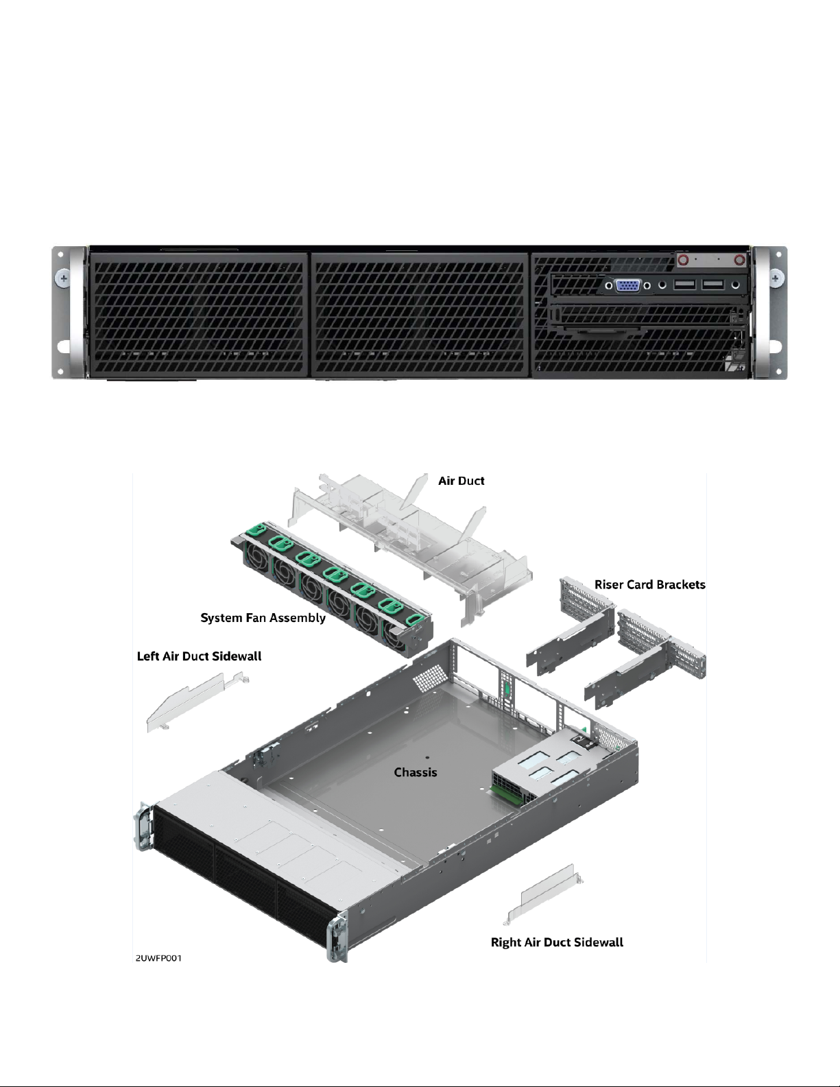
1.1.1 Chassis Component Identification
Figure 2. Chassis Components
18
Page 19

Intel® Server System R2000WF Product Family System Integration and Service Guide
1.2 Prepare Chassis for Assembly
As received, the Intel Server Chassis will include several components within a boxed accessory kit or placed
within the chassis.
1. Remove the System Cover
Note: A non-skid surface or a stop behind the server system may be needed to prevent the server system
from sliding on your work surface
Figure 3. Chassis Cover Removal
a) Loosen the two captive thumb screws located on the back edge of the system cover (See letter “A”)
Note: New chassis as shipped from Intel will require a screw driver to loosen the thumb screws
securing the top cover to the chassis.
b) Slide cover back and lift upward (see letter "B").
The accessory kit and or system packaging will include the following components:
The left and right black plastic air duct sidewalls
Separate bags of screws for mounting the server board and riser card module
RAID Maintenance Free Backup Unit (RMFBU) mounting plate and screws
DIMM Blanks
Black Mylar “No CPU” processor socket spacers
The following components will be found inside the chassis. Each should be removed:
Clear plastic air duct and sidewalls
A box with two processor heat sinks
Two riser card brackets
The system fan module
19
Page 20
Intel® Server System R2000WF Product Family System Integration and Service Guide
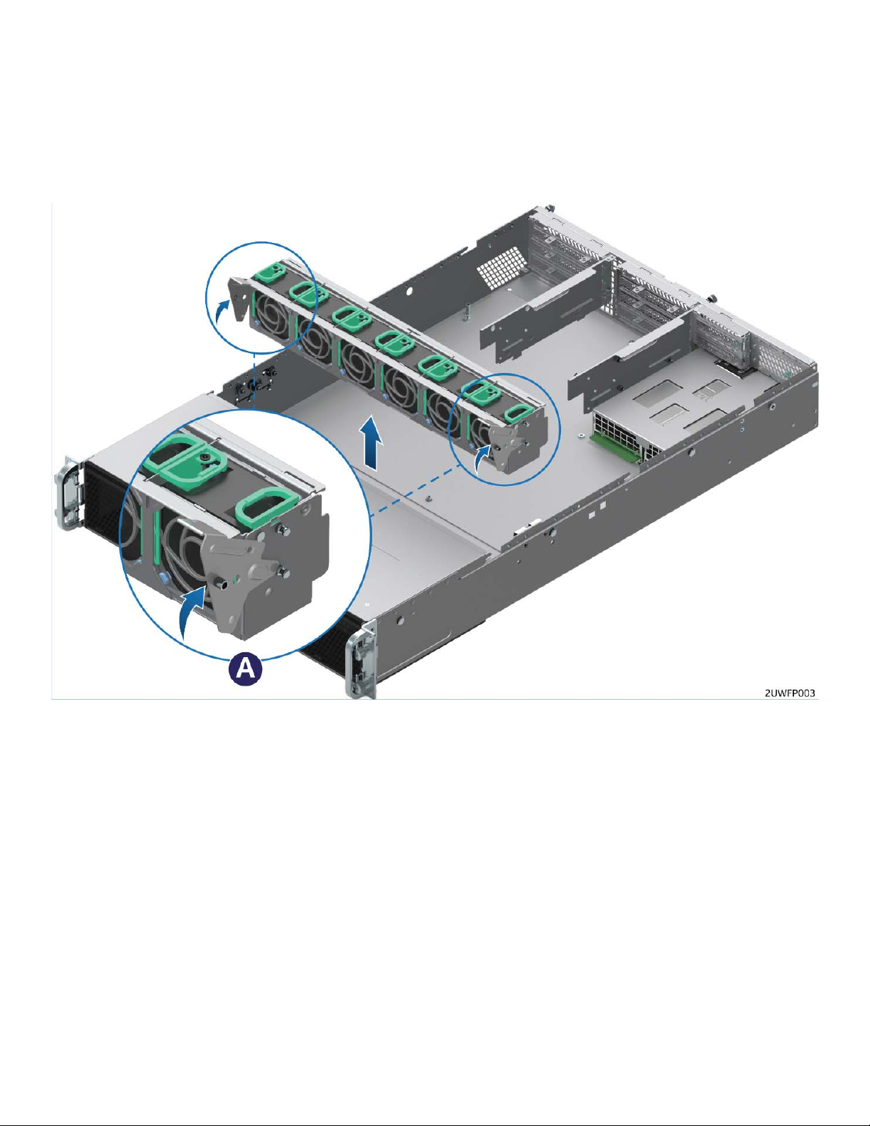
2. Remove the System Fan Module
Figure 4. System Fan Module Removal
a) Lift the latches located on each end of the fan module until each latch is fully disengaged from the
latch receivers on the chassis side wall.
b) Grasp each end of the fan module and pull straight up until the module is fully disengaged from the
module receivers on the chassis side wall.
c) Carefully place the fan module face down onto a flat surface. Do NOT rest the fan module on the
fan connectors located on the bottom side of the fan module, doing so may damage the connectors.
20
Page 21
Intel® Server System R2000WF Product Family System Integration and Service Guide
1.3 System Assembly
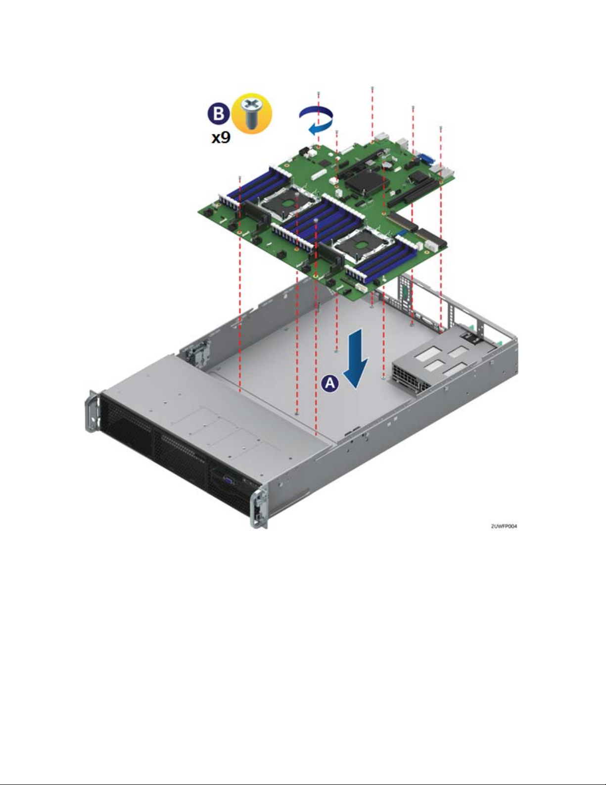
1. Install the Server Board
Figure 5. Server Board Installation
a) Clear the area for server board placement by carefully moving aside any cables that may be taped to
the chassis base.
b) Remove power supplies if present.
c) Remove the server board from its anti-static bag.
d) Holding the server board by its edges, carefully lower the server board into the chassis so that the
rear I/O connectors of the server board align with and are fully seated into the matching cut outs on
the chassis back panel and each server board mounting hole is aligned with a threaded chassis
standoff. (See letter “A”)
e) The server board is accurately placed when the two end screw holes nearest the front edge of the
server board sit securely onto the shouldered chassis standoffs.
f) Using 8 in-lb torque, fasten down the server board with 9 screws (See letter “B”)
21
Page 22
Intel® Server System R2000WF Product Family System Integration and Service Guide
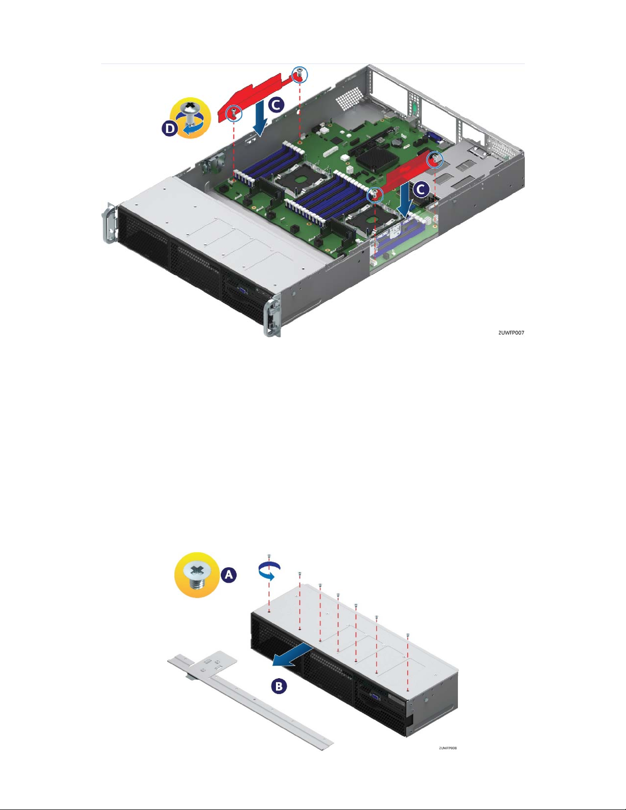
2. Install the Air Duct Side Walls
Figure 6. Air Duct Side Wall Installation
a) Locate the two black plastic air duct sidewalls from the chassis accessory kit
b) Following the illustration above, fasten down the appropriate air duct side wall onto each side of the
server board using 8 in/lbf torque for each screw. (See Letter “C”)
1.3.1 8 x 2.5” Front Drive Bay Module Installation (Intel® Server Chassis R2000WFxxx and
Intel® Server System R2208WFxxxx)
Continue with the instructions in this section for installation of several available 8 x 2.5” front drive bay
accessory kits into the system. If the final system configuration does not include front drive support, proceed
to section 1.3.2
1. Remove the Drive Bay Retention Bracket
The Drive Bay Retention Bracket must be removed in order to remove the Drive Bay Filler Panels.
Figure 7. R2000WFxxx Drive Bay Retention Bracket Removal
22
Page 23
Intel® Server System R2000WF Product Family System Integration and Service Guide
a) Remove the six (6) screws from the top front edge of the drive bay
b) Pull the metal bracket straight out.
c) Set aside the retention bracket and screws for re-installation at a later time.
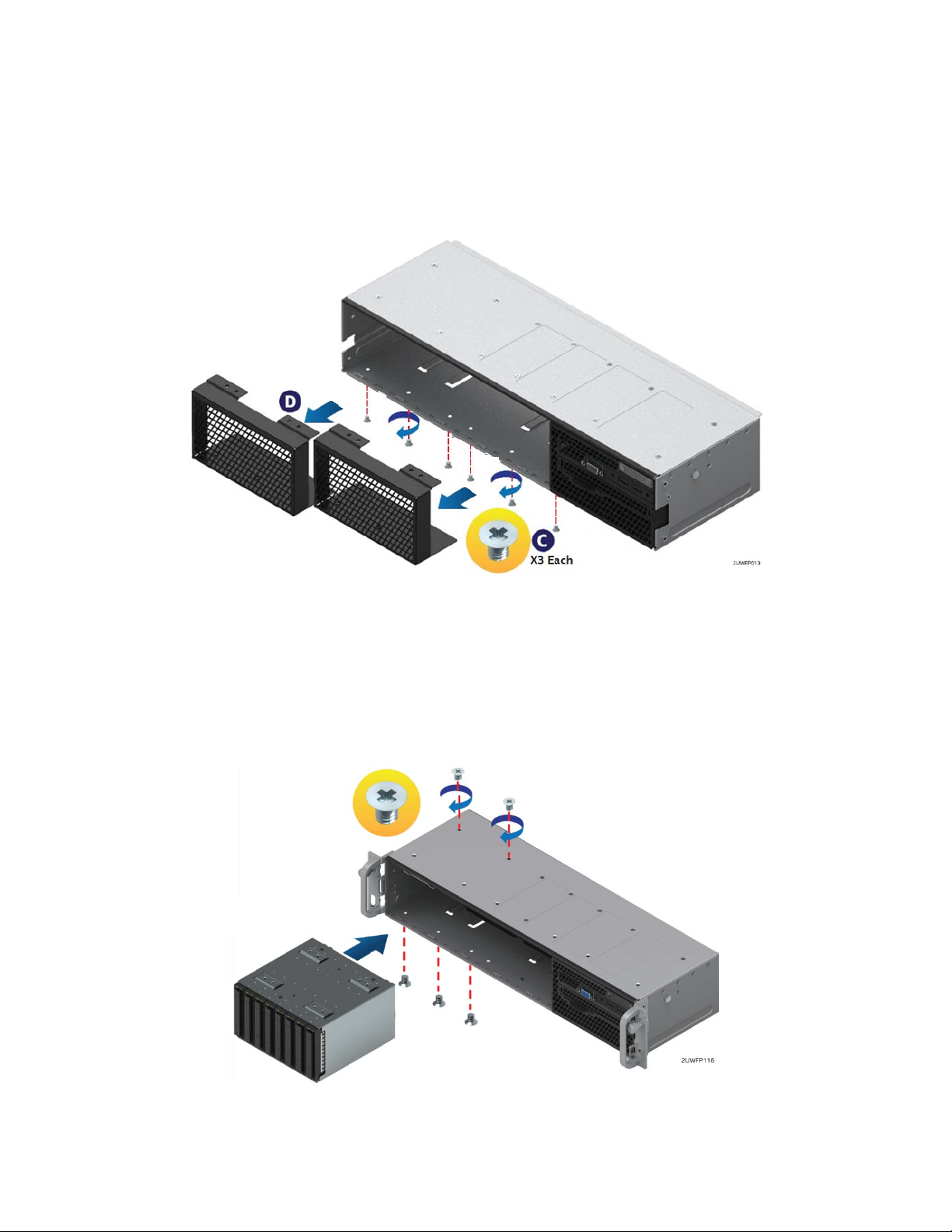
2. Remove Drive Bay Filler Panel(s)
The chassis includes a drive bay filler panel for each drive bay location that doesn’t have a drive bay preinstalled. Remove the filler panel for each 8 x 2.5” drive bay module to be installed.
Figure 8. Drive Bay Filler Panel Removal
a) Carefully turn the chassis onto its side, exposing the bottom side of the chassis.
b) From the bottom of the chassis, remove the three (3) screw securing the given drive bay filler panel
(see Letter ‘C’).
c) Carefully return the chassis to its original position.
d) Slide out the drive bay filler panel (see Letter ‘D’).
3. Insert 8 x 2.5” Drive Bay Module
Figure 9. 8 x 2.5" Drive Bay Module Installation
a) Carefully unpack the 8 x 2.5” drive bay module from the accessory kit.
b) Slide the 8 x 2.5” drive bay module into the server chassis
23
Page 24
Intel® Server System R2000WF Product Family System Integration and Service Guide
c) Using two screws on the top back edge of the drive bay, secure the drive bay to the chassis. (8 in/lbf
torque for each screw).
d) Repeat steps 1-3 for the second drive bay module (if applicable).
e) Carefully place the chassis on its side, and secure each installed drive bay module with three (3)
additional screws on the bottom of the chassis (8 in/lbf torque for each screw).
f) Carefully return the chassis to its original position.
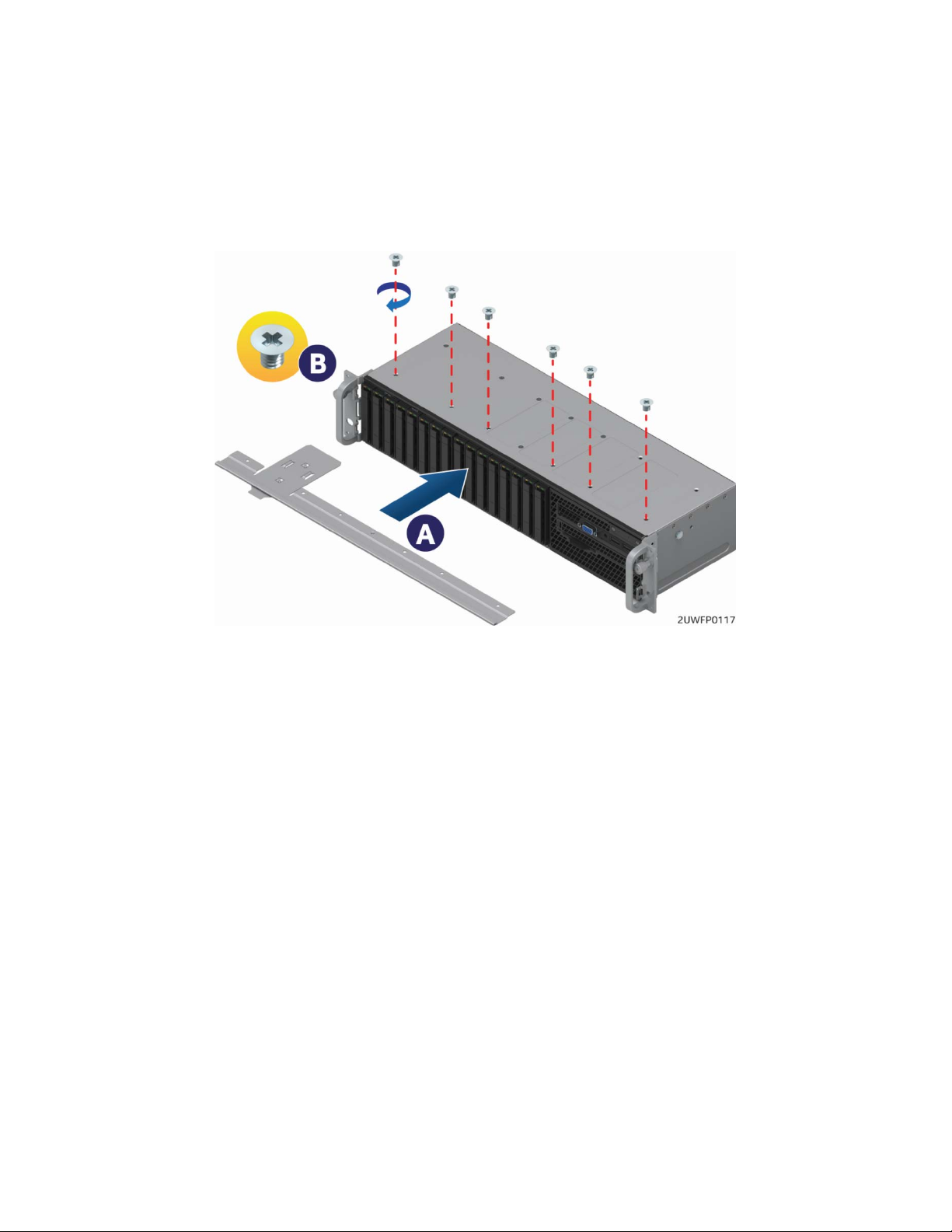
4. Install Drive Bay Retention Bracket
Figure 10. Drive Bay Retention Bracket Installation
a) Locate the drive bay retention bracket and screws.
b) Carefully slide the drive bay retention bracket straight into the gap between the top of the drive bay
module(s) and the underside of the chassis sheet metal. (See Letter ‘A’).
c) Secure the retention bracket with six screws (see Letter ‘B’). (8 in/lbf torque for each screw).
1.3.2 Internal Cable Routing and Connections
All cables in the system that need to be routed from front-to-back, should be routed using the cable
channels between the chassis sidewalls and the air duct sidewalls as shown in the following illustration.
When routing cables front-to-back, none should be routed through the center of the system or in the area
between the system fans and the DIMM slots. Cable connection instructions provided in this section are
presented in the recommended order in which they should be installed. See Error! Reference source not
found. for additional System Cable routing illustrations.
24
Page 25

Intel® Server System R2000WF Product Family System Integration and Service Guide
Figure 11. Internal Cable Routing Channels
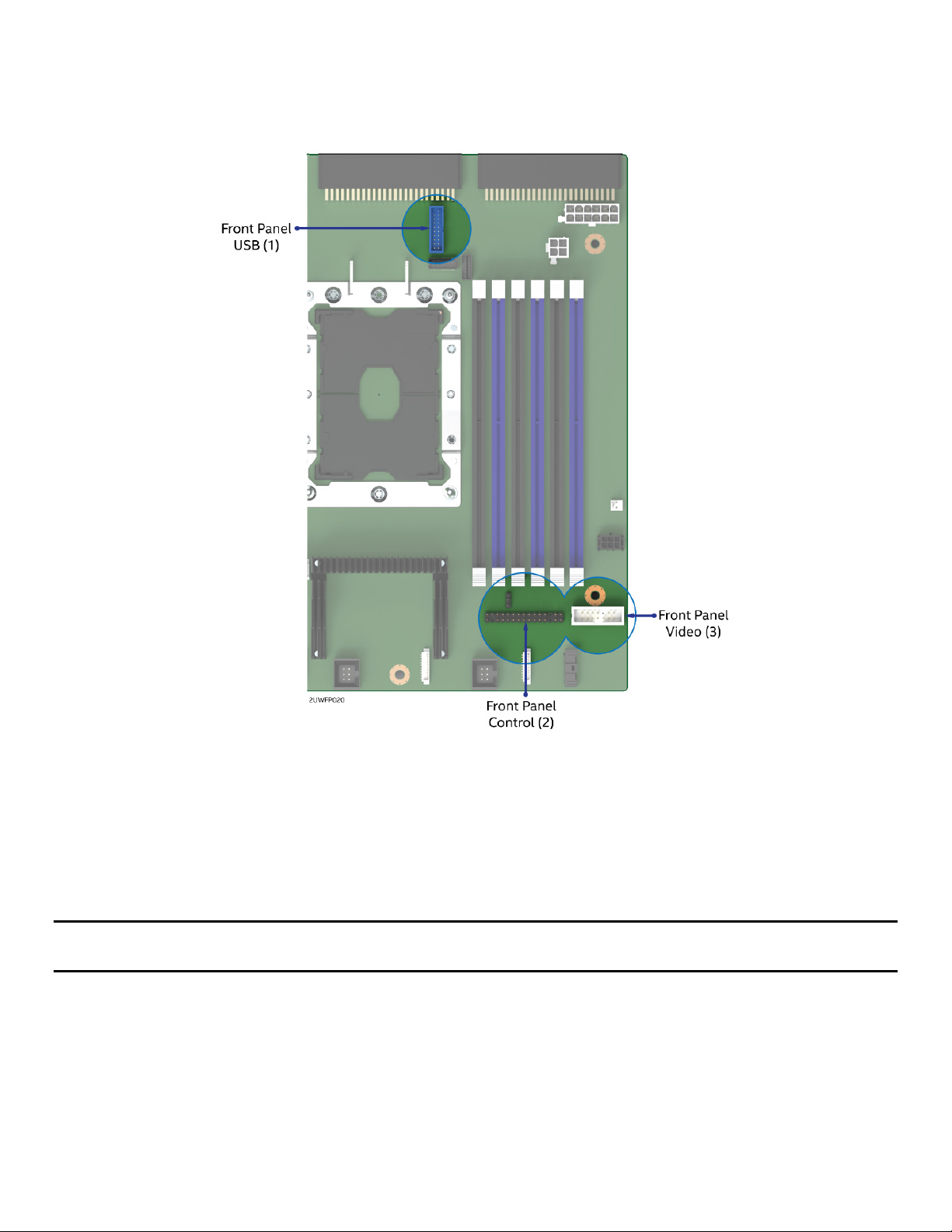
1. Connect Internal Cables for Front Control Panel and Front I/O Module
This system includes front panel USB, Video, Control Buttons, and various LED features that must be cabled
to the appropriate connectors on the server board. Cables should be routed in the following order: (1) Front
Panel USB, (2) Front Control Panel, and (3) Front Panel Video.
25
Page 26
Intel® Server System R2000WF Product Family System Integration and Service Guide
Figure 12. Front Control Panel and Front I/O Internal Cable Connections
a) Route the black round USB cable to the blue 20-pin connector on the server board labeled
“FP_USB2_11_13”. The cable should be routed as close to the chassis side wall as possible.
b) Route the folded 30-pin gray ribbon cable to the matching 30-pin header on the server board
labeled “SSI_FRONT_PANEL”.
c) Route the 14-pin gray folded ribbon cable to the 14-pin black shrouded connector on the server
board labeled “FP_VIDEO”.
Note: With the system fan module assembly removed from the chassis, all three front panel cables should
be routed beneath the fan module receiver feature on the right chassis sidewall.
System configurations with no front drive bay, can proceed to section 1.3.4
26
Page 27
Intel® Server System R2000WF Product Family System Integration and Service Guide
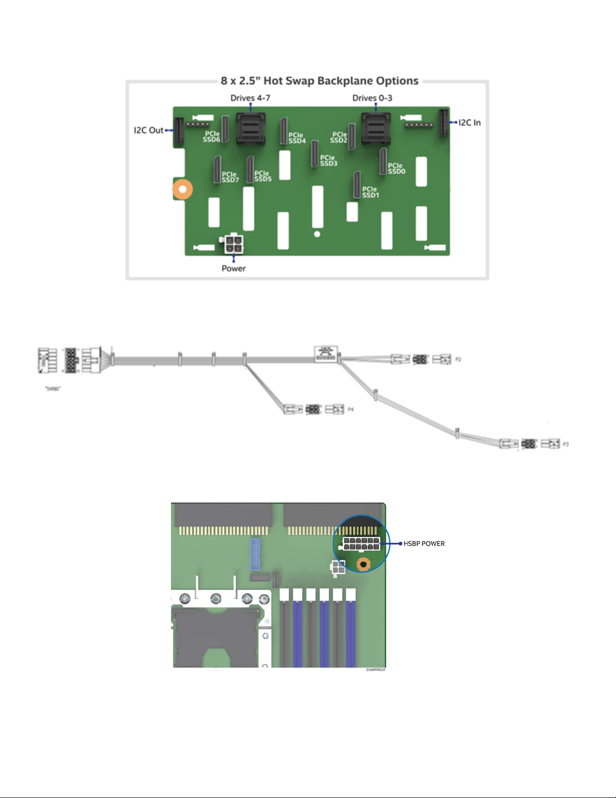
2. Connect the Hot Swap Backplane Power Cable and I
Figure 13. Hot Swap Backplane Connectors
a) Locate the backplane power cable.
2
C Cables
Figure 14. 2.5” Drive Module Hot Swap Backplane Power Cable
Figure 15. HSBP POWER Connector
b) Connect the 2x6 pin cable connector (labeled “SVRBRD”) to the matching 2x6 white power
connector on the server board (silk screened “HSBP PWR”)
27
Page 28
Intel® Server System R2000WF Product Family System Integration and Service Guide
c) Route the backplane power cable along the chassis sidewall, to the area behind the drive bay.
d) Connect the white 2x2 pin cable connector(s) (labeled ‘P#’) to the matching white 2x2 power
connector(s) on the backplane (silk screened ‘PWR’).
e) Once the cable is attached on both ends, carefully press the cable as low as possible into the cable
routing channel.
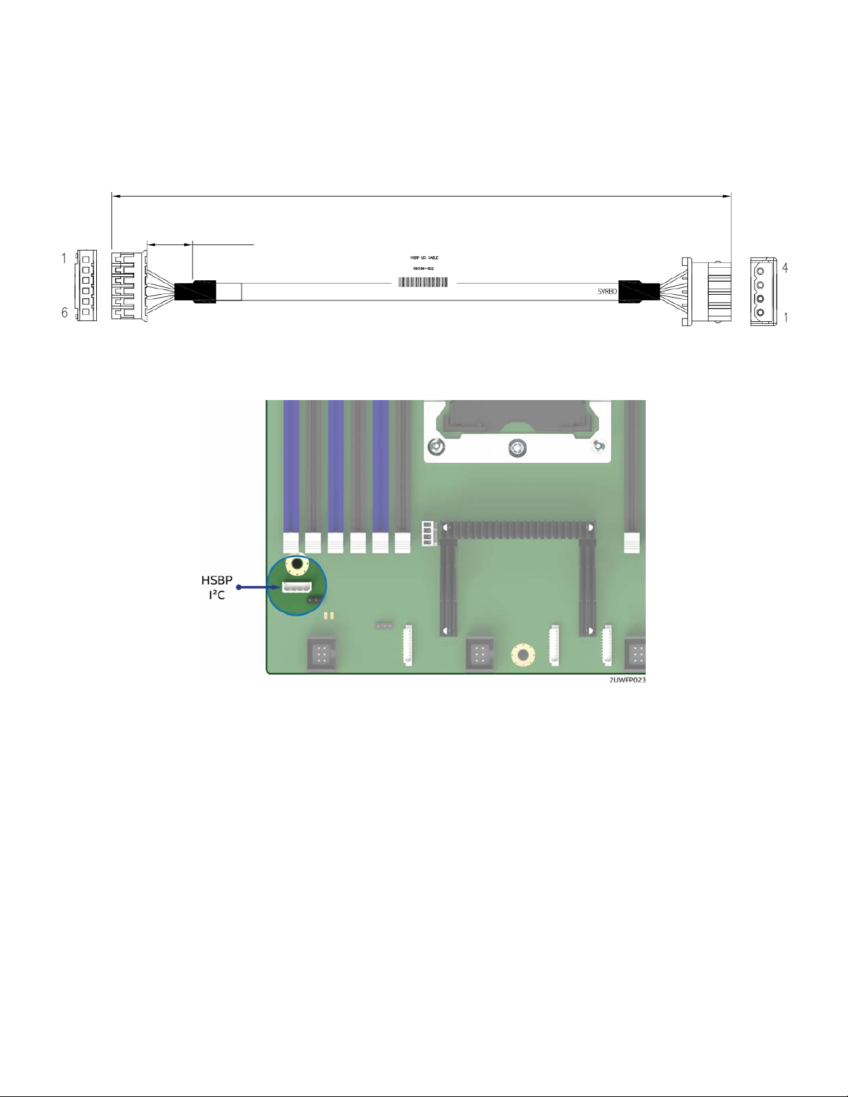
f) Locate the backplane I2C cable.
Figure 16. I
2
C cable
2
Figure 17. Hot Swap Backplane I
C Internal Cable Connector
g) Attach the connector (labeled “HSBP”) of the I2C cable to the matching HSBP pin connector (silk
screened “HSBP I2C”) on the backplane.
h) Route the backplane I2C cable next to the nearest chassis sidewall and connect the other end of the
I2C cable to the 1x4 pin connector (silk screened “HSBP I2C”) on the server board.
28
Page 29
Intel® Server System R2000WF Product Family System Integration and Service Guide
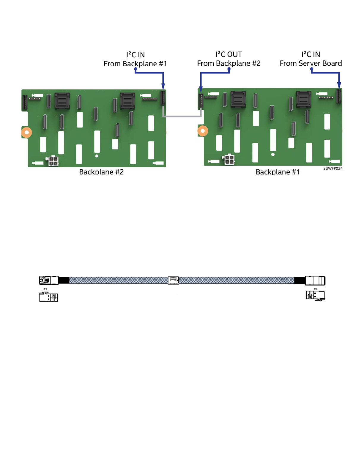
If more than one 8 x 2.5” backplane is being installed, locate the I
2
cable to the I
C -OUT connector of backplane #1 and the other end of the cable to the I2C - IN connector of
backplane #2.
Figure 18. Dual 8x2.5" Hot Swap Backplane I
2
2
C jumper cable and connect one end of the
C Jumper Cable Installation
3. Connect the SAS/SATA Data Cable(s)
SAS/SATA Data cable connections will vary depending on the system configuration. This section will only
describe cable connections when using the onboard SATA controllers. For other add-in storage options,
refer to the appropriate option installation sections available in this document.
a) Locate the appropriate SAS/SATA Data cables.
Figure 19. SATA Cable
b) Attach one side of the SAS/SATA Data cables to the mini-SAS HD connectors on the backplane.
c) Route the SAS/SATA DATA cables from the backplane to the back of the system via the cable
channels next to the chassis sidewalls.
29
Page 30
Intel® Server System R2000WF Product Family System Integration and Service Guide
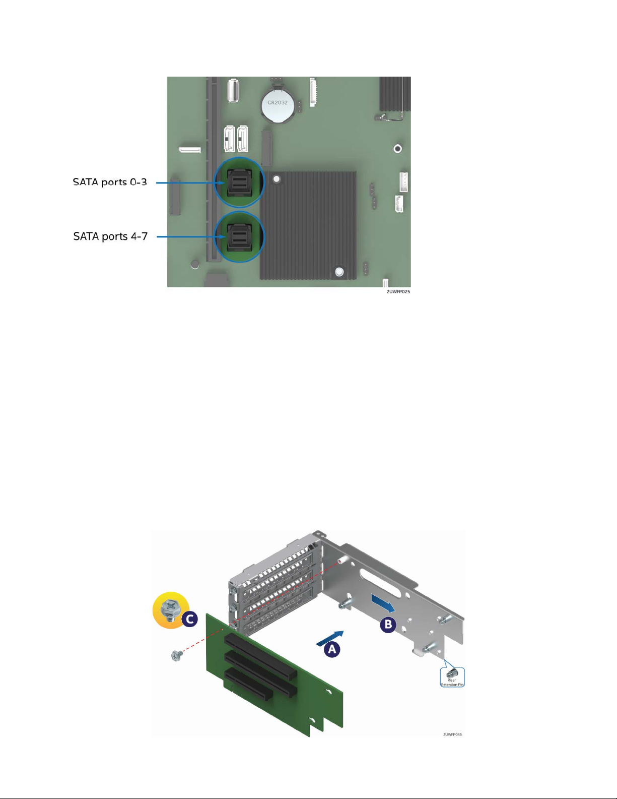
Figure 20. Onboard Connectors for Embedded SATA Support (S2600WFT and S2600WF0 only)
d) Attach the P2 end of the SATA Data cables to the on-board Mini-SAS HD connectors for embedded
SATA support (see Figure 20).
1.3.3 PCIe NVMe Support
See Section 2.10
1.3.4 Riser Card Assembly
The server system can support up to three (3) PCIe riser cards via the two riser card brackets. This section
will provide instructions for mounting of a riser card option to the bracket only. Add-in card installation and
system integration procedures for the riser card assemblies are continued in Chapter 2 after the installation
of other required system components has been performed.
1. Attach Riser Card(s) to Riser Card Bracket(s)
Figure 21. Riser Card Assembly
30
Page 31
Intel® Server System R2000WF Product Family System Integration and Service Guide
a) Locate the screw from chassis accessory kit
b) Locate and remove the riser card from its packaging
c) Position the mounting key holes of the riser card over the riser bracket mounting studs (see letter
“A”) and slide back (see letter “B”)
d) Using the screw from the chassis accessory kit, secure the riser card to the bracket (see Letter “C”).
e) See Section 0 for PCIe add-in card installation procedure
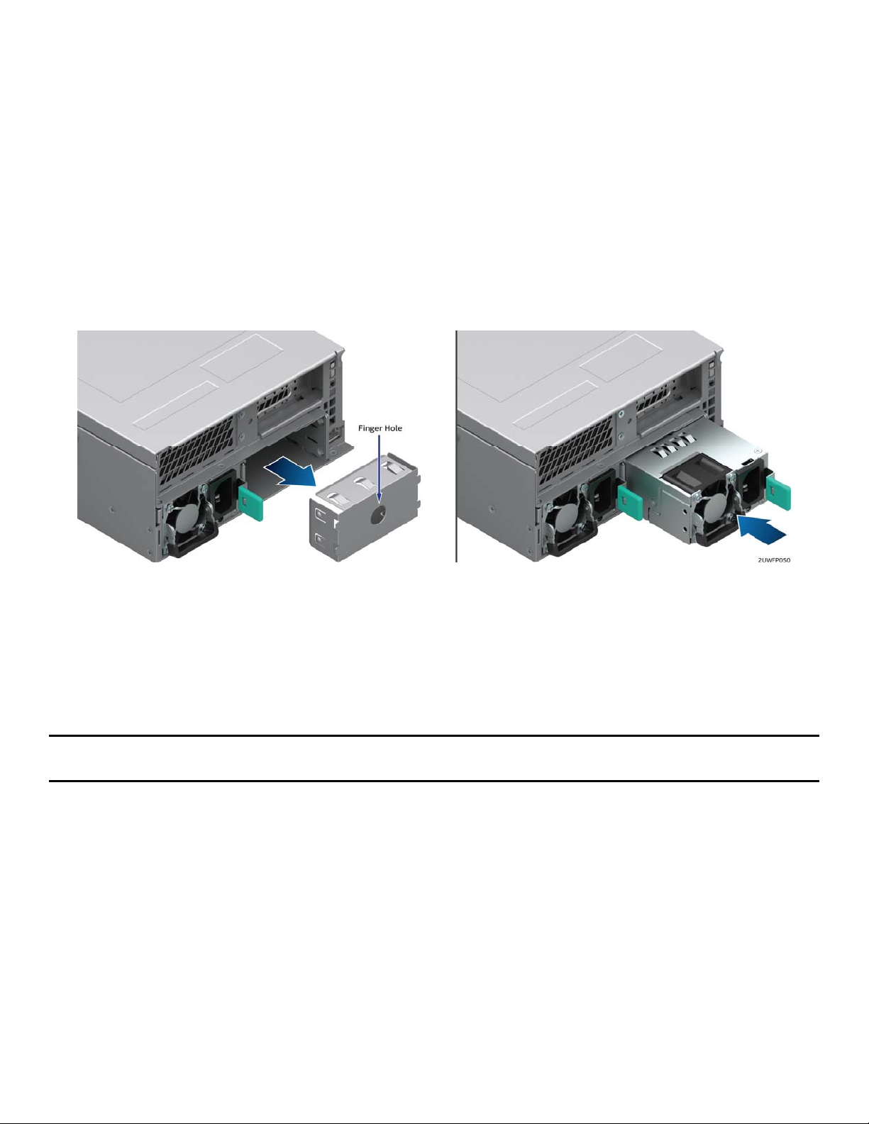
1.3.5 Power Supply Installation
The server system can support 1 or 2 power supply modules. Single power supply configurations must have
the power supply bay insert installed when the system is operational.
1. Install the Power Supply Module(s)
Figure 22. Power Supply Installation
st
a) Insert the 1
b) (Optional) To install a 2
c) (Optional) Install the 2
power supply into the left most power supply bay until it clicks and locks into place.
nd
power supply, remove the insert from the 2nd chassis power supply bay
nd
power supply
Note: A single power supply configuration requires that the power supply bay insert be installed when the
system is operational.
Continue on to Chapters 2 and 3 for installation of processors, memory, add-in cards, storage devices, and
other supported options.
31
Page 32

Intel® Server System R2000WF Product Family System Integration and Service Guide
2. Essential System Component Installation and Service
Purpose
This chapter provides instructions for the installation and removal of essential system components including
processors, memory, storage devices, and add-in cards.
If you are continuing the system integration from the previous chapter, you may skip ahead to section 2.5.
Before You Begin
Before working with your server product, observe the safety and ESD precautions found in the Warnings
section at the beginning of this manual.
Tools and Supplies Needed
T-30 Torx screwdriver
Flat head screwdriver
Adequate ESD protective gear (wrist strap, ESD mat)
System Reference
All references to left, right, front, top, and bottom assume the reader is facing the front of the chassis.
Instruction Format
Each procedure described in this section will follow an illustration first format. This format will give the
reader the option to follow a quicker path to system integration by first seeing an illustration of the intended
procedure. If necessary, the reader can then follow the step-by-step instructions that will accompany each
procedure.
32
Page 33

Intel® Server System R2000WF Product Family System Integration and Service Guide
2.1 Internal Cable Routing Channels
The system fan module must be removed when routing cables from front-to-back. All cables should be
routed using the cable channels in between the chassis sidewalls and the air duct side walls, as shown in the
following illustration. When routing cables front-to-back, none should be routed through the center of the
system or in the area between the system fans and the DIMMs slots.
Figure 23. Internal Cable Routing Channels
33
Page 34

Intel® Server System R2000WF Product Family System Integration and Service Guide
2.2 System Cover Removal / Installation
2.2.1 System Cover Removal
The server system must be operated with the system cover in place to ensure proper cooling. The top cover
must be removed to add or replace components inside of the system. Before removing the top cover, power
down the system and unplug all peripheral devices and the power cable(s).
Note: A non-skid surface or a stop behind the server system may be needed to prevent the server system
from sliding on your work surface. A screw driver may be needed to loosen the top cover thumb screws.
Figure 24. System Cover Removal
1. Loosen the two captive thumb screws located on the back edge of the system cover (See Letter ‘A’)
2. Slide cover back and lift upward (see Letter ‘B’).
2.2.2 System Cover Installation
Figure 25. System Cover Installation
1. Place the system cover onto the chassis and slide forward until the front edge of the system cover is
pressed up against the back edge of the front drive bay. (See letter ‘B’)
2. Hand tighten the two captive thumb screws at the back of the chassis (see letter ‘A’)
Note: For safety after performing service inside of the system, the top cover must be reinstalled and the
thumbscrews tightened to 8in/lb torque or to where the use of a tool is required to re-enter the server.
34
Page 35

Intel® Server System R2000WF Product Family System Integration and Service Guide
2.3 Air Duct Removal / Installation
Always operate your server system with the air duct in place. The air duct is required for proper airflow within
the server system.
2.3.1 Air Duct Removal
Figure 26. Air Duct Removal
1. To remove the air duct, unlatch the rear tabs ‘A’ from underneath each riser card module.
2. Using rear tab posts, lift the air duct straight up until tabs on the front edge of the air duct are free from
the fan module.
2.3.2 Air Duct Installation
Figure 27. Air Duct Installation
1. Align the three tabs on the front edge of the air duct with the matching slots on the fan module.
2. Lower the air duct into the system ensuring the three tabs are securely installed in the fan module.
35
Page 36

Intel® Server System R2000WF Product Family System Integration and Service Guide
3. Press down on the back edge of the air duct so that the tabs at the end of each air duct post snaps
underneath the top edge of the riser card assemblies. The air duct should lay/be flat and secure.
2.4 System Fan Module Removal / Installation
System fan module removal is required whenever routing cables inside the chassis from back to front or
from front to back, or when server board replacement is necessary.
2.4.1 System Fan Module Removal
Figure 28. System Fan Module Removal
36
Page 37

Intel® Server System R2000WF Product Family System Integration and Service Guide
To remove the system fan module:
1. Lift the latches located on each end of the fan module until each latch is fully disengaged from the latch
receivers on the chassis side wall. (see Letter ‘A’)
2. Grasp each end of the fan module and pull straight up (see Letter ‘B’)
3. Carefully place the fan module face down onto a flat surface. Do NOT rest the fan module on the fan
connectors located on the bottom side of the fan module, doing so may damage the connectors.
2.4.2 System Fan Module Installation
Figure 29. System Fan Module Installation
To install the system fan module:
1. Ensure that all cables are clear of the fan module keep out area on the base of the chassis.
2. Ensure the latches on both sides of the fan module are fully rotated up.
3. Position the fan module over the chassis so that the latches are oriented toward the front of the chassis
(see letter ‘A’).
4. Align the two guide pins on each side of the fan module with the latch receivers located on each chassis
sidewall (see letter ‘B’).
5. Carefully lower the fan module into the latch receivers.
6. Push down on both ends of the fan module until fully seated.
7. Rotate each latch down to lock the fan module in place.
37
Page 38

Intel® Server System R2000WF Product Family System Integration and Service Guide
2.5 Processor Assembly, Installation, and Replacement
Components Required:
1 or 2 Intel® Xeon® processor Scalable family
1 or 2 processor clips – Standard and/or Fabric
2 Processor Heat Sink(s)
Tools Required:
T-30 Torx screwdriver
Flat head screwdriver
Adequate ESD protective gear (wrist strap, ESD mat)
This generation of Intel Server Systems requires that the processor be attached to the heat sink prior to
installation on to the server board. The processor / heat sink assembly is referred to as the processor heat
sink module, or PHM.
Figure 30. Processor Heat Sink Module (PHM) Reference Diagram
To properly assemble the PHM and install it to the server board, the procedures described in the following
sections must be followed in the order specified. These instructions assume that all the PHM components
are new and the Thermal Interface Material (TIM) is already applied to the bottom of the heat sink.
Note: Intel Server Systems include two processor clips to support standard Intel® Xeon processors. For Intel®
Xeon® processors that include an Intel® Omni-path host interface connector, a Fabric processor clip must be
used in place of the standard processor clip. Fabric processor clips are included with the following Intel
Fabric processor accessory kits: AWF1PFABKITM or AWF1PFABKITP
WARNING: Attempting to use a Standard CPU Clip with a Fabric supported CPU may result in component
damage and/or induce improper assembly of the PHM.
38
Page 39
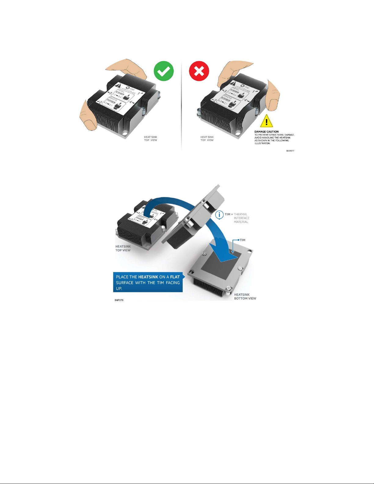
Intel® Server System R2000WF Product Family System Integration and Service Guide
2.5.1 PHM Assembly
1. Remove the heat sink from its packaging. To avoid damage to the heat sink, grasp it by its narrower, top
and bottom edges, as shown below.
Figure 31. Processor Heat Sink Handling
2. Place the heat, sink bottom side up, on to a flat surface as shown.
Figure 32. PHM Assembly – Heat Sink Orientation
3. If present, carefully remove the plastic protective cover from the bottom side of the processor to expose
the Thermal Interface Material (TIM)
4. Locate the processor clip and place it on to a flat non-skid surface with corner latch pins facing down
5. Carefully remove the processor from its packaging. A processor should only be grasped by its edges.
Do not touch any part of the component side of the processor with your fingers.
39
Page 40

Intel® Server System R2000WF Product Family System Integration and Service Guide
Figure 33. Processor Carrier Clip Assembly
6. Orient the processor, component side up, so that all alignment features match those of the processor clip
as shown.
Figure 34. Processor Carrier Clip Sub-Assembly
7. Install the processor into the processor clip until it snaps into place.
CAUTION: To prevent the processor from falling out of the processor clip, the processor / clip assembly
should only be grasped by its shorter edges.
CAUTION: Do not touch the sensitive contacts on the bottom side of the processor at any time during PHM
assembly or installation. In addition, the pins inside the processor socket are extremely sensitive. A damaged
processor socket may produce unpredictable system errors
40
Page 41

Intel® Server System R2000WF Product Family System Integration and Service Guide
Figure 35. Processor Clip Sub-assembly to Heat Sink Orientation
8. Orient the processor clip sub-assembly over the processor heat sink so that all corner features are in
alignment. Ensure Pin 1 indicators are aligned as shown in the following figures.
Figure 36. Processor Heat Sink Module (PHM)
9. Push the processor clip sub-assembly down on to the processor heat sink until it snaps into place,
ensuring all four corners are secure. Processor clip sub assembly should sit flat on top of the heat sink.
2.5.2 Processor Installation
Intel server systems support the installation of 1 or 2 processors. For the server to be operational, CPU #1
must be installed. The installation of CPU #2 is optional, however, to ensure proper airflow when the server
system is operational, the CPU #2 heat sink must be installed at all times. When no processor is installed in a
socket, one of the provided black Mylar spacers should be installed between the processor heat sink and the
processor socket. This is a serviceability feature that identifies that a socket has no processor present when
only a heat sink is installed
41
Page 42

Intel® Server System R2000WF Product Family System Integration and Service Guide
1. Remove the plastic cover from the processor socket on the server board
Figure 37. Plastic processor socket cover removal
a) Grasp the processor cover as shown (see Letter A)
b) Carefully pull it up away from the processor socket, ensuring no contact is made with any of the pins
within the socket. (see Letter B)
NOTE: The processor socket cover should be saved for future use.
CAUTION: When re-installing the socket cover, make sure it properly snaps into place. Improper installation
will cause it to become loose and damage the processor socket.
The assembled PHM and the processor socket include several alignment features to ensure the PHM can
only be installed one way. Care should be taken to ensure components are accurately assembled and the
PHM is oriented correctly to the processor socket prior to placement onto the server board.
Wide Alignment
Screw #1
(Pin #1)
Narrow Alignment
Guide Hole
Guide Hole
Wide Alignment
Guide Pin
Figure 38. Processor Installation Alignment Features
42
Narrow Alignment
Guide Pin
Page 43
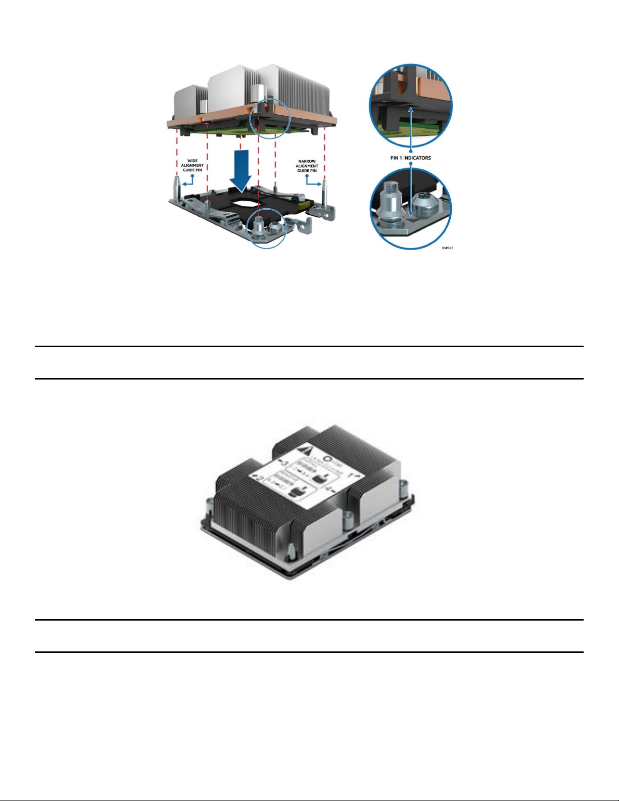
Intel® Server System R2000WF Product Family System Integration and Service Guide
2. Install PHM assembly to the processor socket on the server board
Figure 39. PHM Alignment to Bolster Plate
a) Align the mounting holes of the PHM (located on diagonal corners) to the guide pins of the
processor socket as shown in the following figure.
3. Lower the PHM onto the processor socket assembly
CAUTION: Processor socket pins are delicate and bend easily. Use extreme care when placing the PHM onto
the processor socket, do not drop it.
The PHM assembly is properly installed when seated flat and evenly upon the processor socket assembly
Figure 40. Correct PHM Placement
NOTE: The PHM is NOT installed properly if it does not sit level with the processor socket assembly.
Improperly installed PHMs cannot be fastened down. PHMs can only be fastened down if correctly installed.
4. Secure PHM to the processor socket assembly
a) Using a T30 Torx bit screwdriver, securely tighten (12 in-lb) each fastener in the sequence shown on
the label located on the top of the heat sink
43
Page 44

Intel® Server System R2000WF Product Family System Integration and Service Guide
Figure 41. Installing the PHM
CAUTION: Failure to tighten the heat sink screws in the specified order may cause damage to the processor
socket assembly. Each heat sink screw should be fully tightened to 12 in-lb torque before securing the next
screw in the sequence.
5. For a second procesor, repeat the processor installation instructions above, ensuring the proper
processor heatsink and processor carrier clip are used for the installation.
nd
For single processor configurations, where a 2
processor is not installed, install the CPU#2 heat on to the
CPU #2 socket to ensure proper air flow when the system is operational.
See section 3.9 for installation instructions related to fabric processor accessory kits.
2.5.3 Processor Replacement
1. Remove Processor from Server Board
WARNING: Processor heat sinks can become extremely hot during normal system operation. Before
attempting to remove the processor from the server board, allow the processor heat sinks to fully cool.
Failing to follow the indicated disassembly sequence, may cause damage
Figure 42. Uninstalling the Processor Heat Sink Module (PHM)
44
Page 45

Intel® Server System R2000WF Product Family System Integration and Service Guide
a) Using a T30 Torx bit screwdriver, loosen each heat sink fastener in the sequence shown on the label
located on the top of the heat sink (see Letter A)
b) Lift the PHM straight up from the server board until it is free from the processor socket bolster plate
guide pins (see Letter B)
Note: to prevent possible damage to the processor socket, re-install the original plastic cover to the
processor socket.
Figure 43. Plastic Processor Socket Cover Installation
2. With the heat sink facing down, place the Processor Heat Sink Module (PHM) onto a flat non-conductive
surface
3. Remove the processor clip sub-assembly from the heat sink:
a) Insert the head of a flat head screw driver in-between the heat sink and the processor clip assembly
(as shown below) and gently twist until the bond between heat sink and the processor is broken.
Figure 44. PHM Disassembly
b) Unlatch the hooks on each corner of the processor clip to free the processor from the heat sink
45
Page 46

Intel® Server System R2000WF Product Family System Integration and Service Guide
Figure 45. Releasing the Processor Carrier Clip from the Heat Sink
c) Carefully lift the processor sub-assembly from the heat sink
4. Remove the processor from the processor clip by carefully pushing back one of the latches located on
the ends of the processor and rotating the processor up and out of the processor clip
Figure 46. Releasing Processor from Processor Clip
For processor assembly and installation, see sections 2.5.1 and 2.5.2
2.6 Memory Module (DIMM) Installation and Replacement
Components Required:
Up to 24 DDR4 DIMMs
General Memory Population Rules:
Memory channels for each processor are identified as A – F. Each memory channel includes two DIMM slots
identified as 1 and 2. On the server board, each DIMM slot is identified by Processor #, Channel Identifier,
and DIMM Slot #.
Examples)
CPU1_DIMM_A1
CPU1_DIMM_A2
CPU2_DIMM_A1
etc….
46
Page 47

Intel® Server System R2000WF Product Family System Integration and Service Guide
BLUE DIMM Slots identify DIMM 1 for each memory channel.
To maintain required air flow within the system, certain memory slots MUST be populated with a DIMM or
supplied DIMM blank. DIMM blanks should only be removed when installing a DIMM in the same DIMM slot.
Figure 47. DIMM Blank
Figure 48. Memory Slot Population Requirements – 8x2.5, 16x2.5, 8x3.5 Front Drive Configurations
Figure 49. Memory Slot Population Requirements – 24x2.5, 12x3.5 Front Drive Configurations
For best performance, DIMMs should be populated using the following guidelines:
Each installed processor should have matching DIMM configurations
The following DIMM population guidelines should be followed for each installed processor
o 1 DIMM to 3 DIMM Configurations – DIMMs should be populated to DIMM Slot 1 (Blue Slot) of
Channels A thru C
o 4 DIMM Configurations – DIMMs should be populated to DIMM Slot 1 (Blue Slot) of Channels A,
B, D, and E
o 5 DIMM Configurations – NOT Recommended. This is an unbalanced configuration which will
yield less than optimal performance
o 6 DIMM Configurations – DIMMs should be populated to DIMM Slot1 (Blue Slot) of all Channels
o 7 DIMM Configurations – NOT Recommended. This is an unbalanced configuration which will
yield less than optimal performance
o 8 DIMM Configurations – DIMMs should be populated to DIMM Slots 1 and 2 of Channels A, B, D,
and E
47
Page 48

Intel® Server System R2000WF Product Family System Integration and Service Guide
o 9 DIMM, 10, DIMM, and 11 DIMM Configurations - NOT Recommended. These are an
unbalanced configurations which will yield less than optimal performance
o 12 DIMM Configurations – DIMMs are populated to ALL DIMM Slots
Note: DIMM populations noted as “Not Recommended” are fully functional configurations. However, they
will not yield the best possible system performance.
2.6.1 DDR4 DIMM Installation
Figure 50. DIMM Installation
1. Locate the DIMM sockets. Make sure the clips at either end of the DIMM socket(s) are pushed outward to
the open position (see letter ‘A’).
2. Holding the DIMM by the edges, remove it from its anti-static package. Position the DIMM above the
socket. Align the notch on the bottom edge of the DIMM with the key in the DIMM socket (see letter ‘B’).
3. Insert the bottom edge of the DIMM into the socket (see letter ‘C’). When the DIMM is inserted, push
down on the top edge of the DIMM until the retaining clips snap into place (see letter ‘D’). Make sure the
clips are firmly in place (see letter ‘E’).
2.6.2 DDR4 DIMM Replacement
1. Locate the DIMM socket for service. Ensure that the retaining clips of adjacent slots are closed.
2. Open the DIMM slot latches at either end of the selected DIMM socket (see Letter A in Figure 51. DIMM
Removal). The DIMM will lift up from the socket connectors.
3. Holding the DIMM by its edges, lift it away from the socket (see Letter B)
Figure 51. DIMM Removal
48
Page 49

Intel® Server System R2000WF Product Family System Integration and Service Guide
2.7 Drive Carrier Extraction, Installation, and Assembly
The 2U server product family has front drive bay chassis options that support 2.5” form factor drives (Hard
Disk Drives or Solid State Drives) or 3.5” form factor hard disk drives with the option to support 2.5” SSDs.
This section provides instruction for drive extraction from the chassis, drive installation into the chassis, and
drive assembly.
Note: To maintain proper system cooling, all externally accessible drive bays must be populated with a drive
carrier. Each drive carrier must have a hard disk drive (HDD), Solid State Device (SSD), or a supplied drive
blank installed.
2.7.1 Drive Carrier Extraction
Figure 52. Drive Carrier Extraction from Chassis
1. Remove the drive carrier from the chassis by first pressing the button on the carrier face plate to release
the lever (see Letter “A”).
2. Using the lever, pull the carrier from the drive bay (see Letter “B”).
2.7.2 Drive Carrier Installation
Figure 53. Drive Carrier into Chassis Installation
1. Align the drive assembly with the open drive bay
2. With the lever in the open position, insert the drive assembly into the drive bay (See letter “A”) and push
forward until the drive makes contact with the backplane
3. Complete the drive installation by closing the drive assembly lever until it locks into place (See letter “B”)
49
Page 50

Intel® Server System R2000WF Product Family System Integration and Service Guide
2.7.3 2.5” HDD / SSD Drive Carrier Assembly
Figure 54. 2.5” Drive Carrier Assembly – Drive / Drive Blank Removal
1. Remove the drive or drive blank from the carrier by gently rotating the top edge of a carrier rail outwards
while at the same time pushing the drive or drive blank up from the bottom (as shown above).
Mounting Tab
(2 on each side)
Mounting Holes
(2 on each side)
Figure 55. 2.5” Drive Carrier Assembly – Drive Installation to Carrier
2. With the rear drive connector positioned towards the back of the drive carrier, align and position the
mounting holes on one side of the drive over the mounting tabs located on the drive carrier side rail (See
letter “A”)
3. Lower the other side of the drive into the carrier (See letter “B”) and press down on the drive until all
mounting tabs are locked in place.
50
Page 51

Intel® Server System R2000WF Product Family System Integration and Service Guide
Note: The 2.5” drive blank and drive carrier each have an alignment feature (shown above) to ensure proper
assembly. When re-installing a drive blank in to the drive carrier, ensure the features are aligned prior to
installation. Failure to properly install a drive blank may result with the carrier assembly not fitting properly
in to the chassis drive bay.
Figure 56. 2.5” Drive Carrier Assembly – Alignment Features
2.7.4 3.5” HDD/SSD Drive Carrier Assembly
Figure 57. 3.5" Drive Carrier Assembly - Drive / Drive Blank Removal
1. Remove the drive or drive blank from the carrier by holding the carrier assembly top side down in your
right hand. Using your left hand, gently rotate the bottom edge of the left rail upwards (see Letter “A”)
while at the same time pushing the drive or drive blank down away from the carrier (see Letter “B”).
51
Page 52

Intel® Server System R2000WF Product Family System Integration and Service Guide
Figure 58. 3.5” Drive Carrier Assembly – Drive Installation to Carrier
2. With the rear drive connector positioned towards the back of the drive carrier, align and position the
mounting holes on the left side of the drive over the mounting tabs located on the drive carrier side rail
(See letter “A”)
3. Lower the other side of the drive into the carrier and press down until all mounting tabs lock in place.
2.7.5 2.5” SSD into a 3.5” Drive Carrier Assembly
The 3.5” drive blank can be used as a 2.5” SSD bracket.
Note: Due to degraded performance and reliability concerns, the use of the 3.5” drive blank as a 2.5” drive
bracket is intended to support SSD type storage devices only. Installing a 2.5” hard disk drive into the 3.5”
drive blank is not supported.
Figure 59. 3.5" Drive Carrier Assembly – Drive Blank Removal
52
Page 53

Intel® Server System R2000WF Product Family System Integration and Service Guide
1. Remove the drive blank from the carrier by holding the carrier assembly top side down in your right
hand. Using your left hand, gently rotate the bottom edge of the left rail upwards (see Letter “A”) while at
the same time pushing the drive blank down away from the carrier (see Letter “B”).
Figure 60. 3.5" Drive Carrier to 2.5” SSD Bracket – Tab Removal
2. Break off the small side tab from the side of the drive blank, making the drive blank into a 2.5” drive
bracket (see Letter “C”).
Note: Once the side tab is removed, it cannot be re-attached to the drive blank
Figure 61. 3.5" Drive Carrier to 2.5” SSD Bracket – Mount SSD to Bracket
3. Mount and secure a 2.5” SSD to the drive bracket using two screws at the locations shown above (See
letter “D”).
Note – New drive carriers with drive blanks installed, will include a bag containing four (4) mounting screws.
53
Page 54

Intel® Server System R2000WF Product Family System Integration and Service Guide
Figure 62. 3.5" Drive Carrier to 2.5” SSD Bracket – Mount Bracket Assembly to Carrier
4. With the rear drive connector positioned towards the back of the drive carrier, align and position the
mounting holes on the left side of the drive bracket over the mounting tabs located on the drive carrier
side rail (See letter “E”)
5. Lower the other side of the drive into the carrier and press down until all mounting tabs lock in place.
(See letter ‘F’)
6. Turn the drive assembly over.
Figure 63. 3.5" Drive Carrier to 2.5” SSD Bracket – Secure SSD to Carrier
7. Using two (2) screws, secure the SSD to the carrier side rail (See letter “G”)
54
Page 55
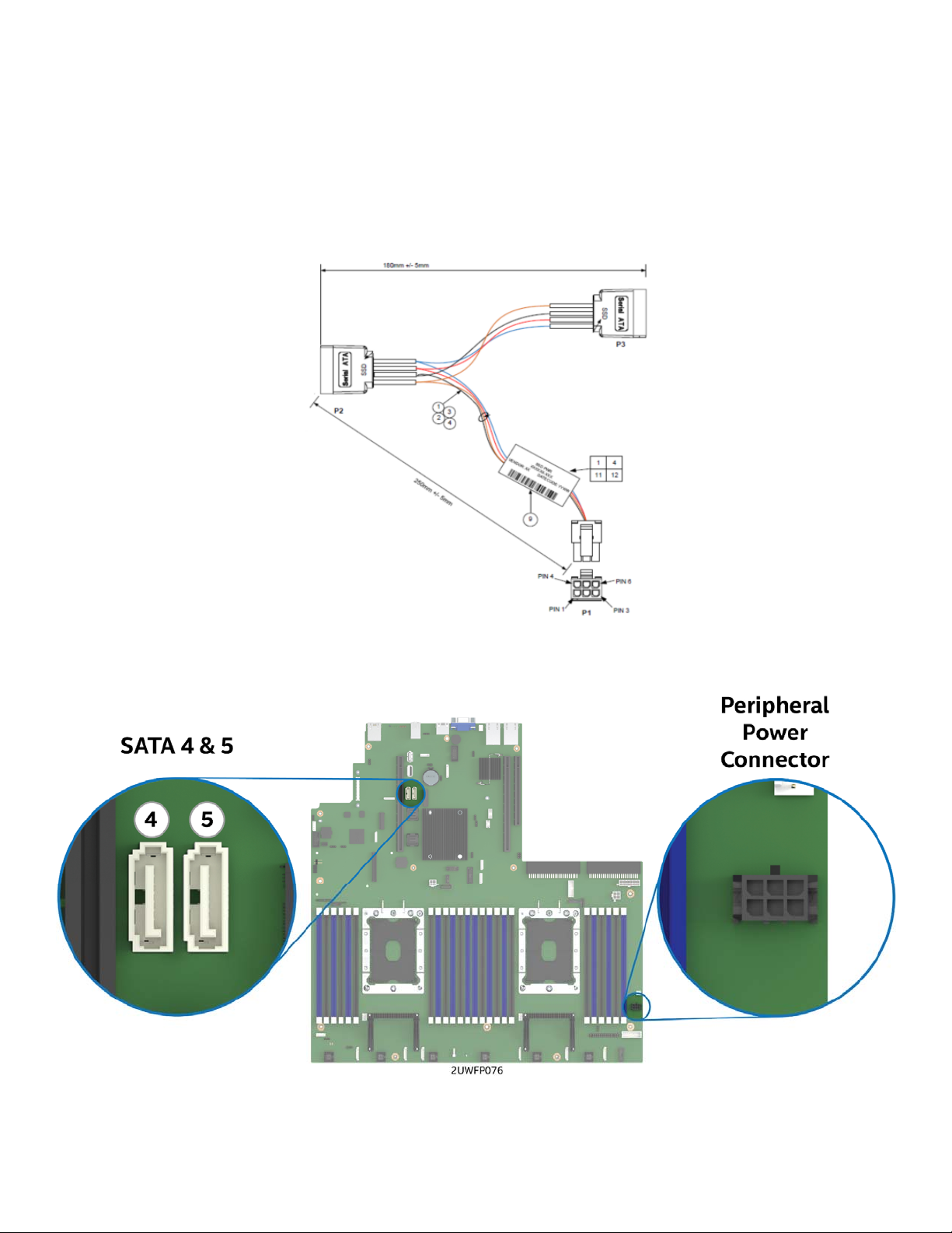
Intel® Server System R2000WF Product Family System Integration and Service Guide
2.8 Internal Fixed Mount SATA SSD – Installation / Removal
The system has support for up to two internal fixed mounted SATA Solid State Devices (SSDs). SSD’s can be
mounted to either of the two available air duct options (Standard or High Air Flow). SSD installation and
removal procedures are the same for both air ducts.
2.8.1 Internal Fixed Mount Solid State Drive Installation
1. From the system’s accessory kit, locate the peripheral device power cable.
Figure 64. Peripheral Device Power Cable
Figure 65. Onboard Peripheral Power and SATA Connectors for Internal SSD support
2. Connect the 2x3 cable connector (labeled “SB”) to the server board “Peripheral PWR” connector
3. Locate the SATA cable and install it to either the “SATA 4” or “SATA 5” ports on the server board
55
Page 56

Intel® Server System R2000WF Product Family System Integration and Service Guide
Figure 66. Internal Fixed Mount SSD Placement
1. Place the Solid State Drive onto the air duct (see Letter ‘A’).
2. Secure the Solid State Drive with four screws (see Letter ‘B’).
3. Install the air duct (see Section 2.3.2).
4. Attach the SATA and Power cables to the SSD (see Letter ‘C’).
2.8.2 Internal Fixed Mount Solid State Drive Removal
Note: The internal fixed mount SSDs are NOT hot-swappable. Before removing or replacing the drive, you
must first take the server out of service, turn off all peripheral devices connected to the system, turn off the
system by pressing the power button, and unplug the power cord from the system or wall outlet.
Figure 67. Internal Fixed Mount SSD Removal
1. Remove the system cover (see Section 2.2.1).
2. Detach the SATA and Power cables from the back of the SSD (see Letter ‘A’).
3. Remove the air duct from the system (see Section 2.3.1)
4. Remove the four screws to release the Solid State Drive (see Letter ‘B’).
5. Remove the SSD from the air duct (see Letter ‘C’).
56
Page 57

Intel® Server System R2000WF Product Family System Integration and Service Guide
2.9 Riser Card Bracket Assembly - Removal / Integration / Installation
The server system can support up to three (3) PCIe riser cards via the two riser card brackets. This section
will provide instructions for the removal and installation of the riser card assemblies from/to the system, and
installation of an add-in card into the riser assembly.
Figure 68. Riser Card Brackets
2.9.1 Riser Card Bracket Removal
Figure 69. Riser Card Bracket Removal
Disconnect all cables attached to any add-in cards. Grasp the riser assembly with both hands and pull up to
remove from the system.
57
Page 58
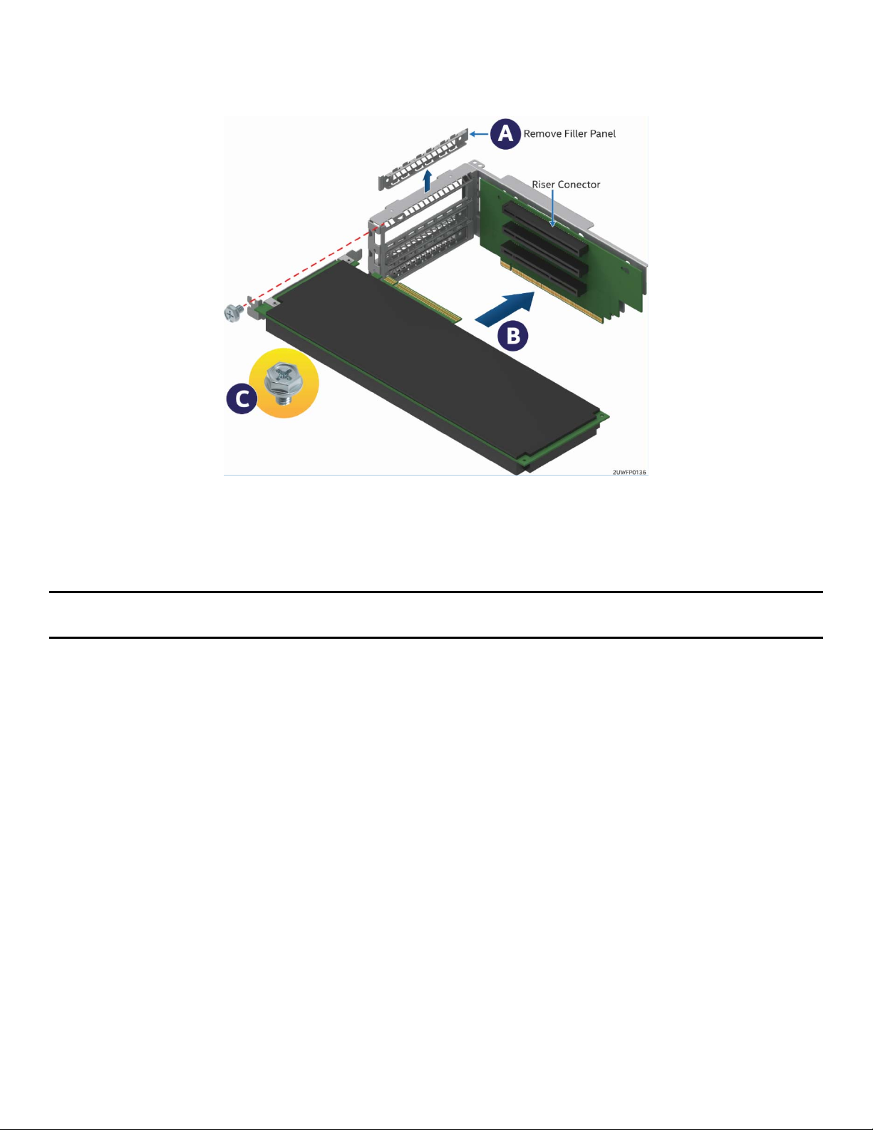
Intel® Server System R2000WF Product Family System Integration and Service Guide
2.9.2 PCI Add-in Card Installation
1. Remove the PCI riser assembly from the system. (see Section 2.9.1.)
Figure 70. PCI Add-In Card Installation
2. Remove the filler panel from the add-in card slot and remove the fastener screw (see Letter ‘A’).
3. Insert the add-in card until it is fully seated inside the PCI slot on the riser card (see Letter ‘B’).
4. Secure the add-in card to the riser bracket with the fastener screw using a 12in/lb torque (see Letter ‘C’).
Note: For add-in cards with internal cable connectors, it may be necessary to connect cables before installing
the riser card assembly into the system.
58
Page 59
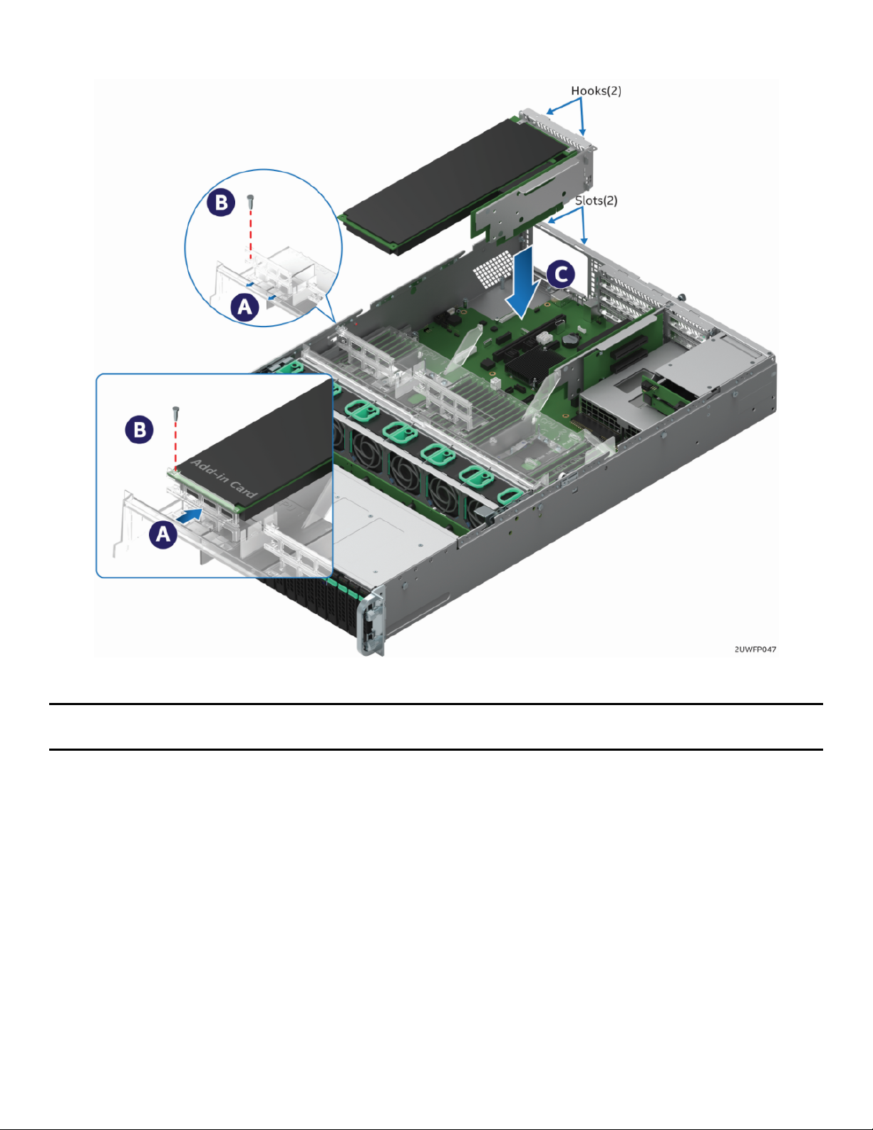
Intel® Server System R2000WF Product Family System Integration and Service Guide
2.9.3 Riser Card Bracket Installation
Figure 71. Riser Card Bracket Installation
Note: Steps 1, 2, 5, 6, and 7 highlighted below are only needed when a full-length PCIe card is installed on
the riser assembly.
1. Slide back the blue card guide on the air duct (see Letter ‘A’).
2. If installed, remove the blue plastic pin from the card guide (see Letter ‘B’).
3. Position the riser card’s edge connector over the riser slot on the server board and align the two hooks
on the back edge of the riser assembly with the slots on the back of the chassis.
4. Once aligned, press the riser assembly straight down into the riser slot (see Letter ‘C’).
5. Slide forward the card guide to lock in the back edge of the full–length add-in card (see Letter ‘A’).
6. Locate the blue plastic pin to secure the back edge of the full-length add-in card to the card guide.
7. Insert the blue plastic pin into the card guide and through the matching hole in the add-in card (see
Letter ‘B’).
8. Connect any cables to the add-in cards that require them. See your add-in card documentation for
additional information.
59
Page 60

Intel® Server System R2000WF Product Family System Integration and Service Guide
2.10 PCIe* NVMe SSD Support
The following 2U backplane options have support for 2.5” small form factor PCIe NVMe SSDs.
2.5” x 8 Combo Backplane (iPC – F2U8X25S3PHS) – Support for up to eight (8) NVMe SSDs per
installed backplane
3.5 x 12 Backplane (iPC – F2U12X35S3PH) – Support for up to two (2) NVMe SSDs
Available options to provide the necessary PCIe data signals to support each installed NVMe drive include:
Up to Four (4) PCIe OCuLink connectors on the server board
4-port PCIe X8 Switch Add-in Card – Accessory Option (iPC AXXP3SWX08040)
8-port PCIe X8 Switch Add-in Card – Accessory Option (iPC AXXP3SWX08080)
Accessory kits for the PCIe Switches, and available PCIe OCuLink cables are sold separately from the system.
Reference the Intel® Server S2600WF Product Family Configuration Guide to determine appropriate cables
necessary to match the desired NVMe drive configuration to a specified PCIe source. Cables identified in the
Configuration Guide are optimized to provide the cleanest cable routing.
The following procedure should be followed when installing data cables from a backplane to a PCIe source.
1. If installed, removed the system fan assembly module (See section 2.4.1)
2. Locate the PCIe OCuLink cable that supports the desired NVMe drive configuration and PCIe source:
a. Onboard OCuLink connectors – One (1) NVMe drive per cable (1 connector at each end of the cable)
b. PCIe Switch Add-in Card – Four (4) NVMe drives per cable (4 connectors at each end of the cable)
3. Attach one end of the cable (1 connector or 4 connectors) to matching PCI_SSD OCuLink connector(s) on
the backplane
4. Route the cable to the nearest chassis sidewall and carefully position it within the cable routing channel
along the sidewall
5. Connect the other end of the PCIe OCuLink cable to the appropriate PCIe source (Onboard OCuLink or
Add-in Switch card)
6. Repeat steps for each OCuLink cable to be installed
7. If no more cables are to be installed, re-install the system fan module (See section 2.4.2)
The following sections provide information necessary to support NVMe RAID and NVMe Management
features. They include instructions for the installation of an Intel® VROC Upgrade Key accessory and
associated drive population / support rules when VROC management features are enabled.
60
Page 61

Intel® Server System R2000WF Product Family System Integration and Service Guide
2.10.1 Installing the Intel® VROC Upgrade Key
Figure 72. Installing the Intel® VROC Upgrade Key
1. Remove the Intel® VROC Key from its packaging.
2. Locate the white 4-pin key connector above the CR2032 battery on the back edge of the server board.
3. To install the key, place it over the connector and confirm the orientation of the key matches that of the
connector.
4. Press the key down onto the connector.
2.10.2 Removing the Intel® VROC Upgrade Key
1. Power off the system and disconnect the power cable(s).
2. Remove the system cover (see Section 2.2.1).
3. Using the key pull tab, pull the key up until it disengages from the connector.
2.10.3 NVMe* Drive Population Rules for Intel® VROC
In order to support NVMe RAID and NVMe Management features, the optional Intel® VROC Key must be
installed on to the server board. With the Intel VROC key installed, specific drive population rules exist and
must be followed for proper support of the NVMe management features.
The backplane can support PCIe interfaces from the onboard OCuLink connectors on the server board,
and/or optional add-in Intel Tri-Mode RAID modules and/or PCIe Switch cards. When cabling the PCIe
interfaces from two different PCIe interface sources to the backplane, the cables from each source must be
connected in defined drive sets of four (0,1,2,3) & (4,5,6,7) as shown in the following diagrams.
Note: OCuLink connectors on the server board (one or all) routed to the backplane is considered a single
source.
Routing OCuLink cables from two or more PCIe sources to a defined drive set is not supported.
61
Page 62
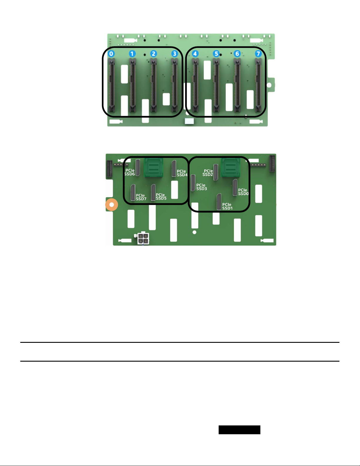
Intel® Server System R2000WF Product Family System Integration and Service Guide
PCIe Source #1
PCIe Source #2
PCIe Source #2
Front Drive Connectors
PCIe Source #1
Back OCuLink Cable Connectors
Figure 73. Backplane Cabling from Two PCIe Sources
When cabling the backplane from two different PCIe sources, no other drive set combinations beyond those
defined above are supported.
Drive population rules will differ depending on the source of the PCIe interface to the backplane. In addition,
specific drive population limits exist when populating a backplane with both NVMe and SAS/SATA drive
types.
The following sections define the drive population rules for each installed 2.5” x 8 combo backplane when
cabled to a specific PCIe source.
NOTE: When connecting the backplane to two different PCIe sources, the defined population rules for each
PCIe source are applied to the drive set connected to it
2.10.3.1 Onboard PCIe OCuLink Connectors and / or Intel Tri-mode RAID module to 8 x 2.5” Combo
Backplane
The following information is applicable when PCIe signals to the 8x2.5” combo backplane are cabled from
the PCIe OCuLink connectors located on the server board and/or an optionally installed Intel® Tri-mode
RAID Module.
OCuLink connectors on the server board are considered a single PCIe source to the backplane, and
therefore can only be connected in defined drive sets: PCIe_SSD (0-3) or (4-7)
62
Page 63

Intel® Server System R2000WF Product Family System Integration and Service Guide
NVMe drive management sideband signals on the backplane are routed between drive connector pairs:
(0,1) (2,3) (4,5) and (6,7)
In order to support NVMe drive management within a defined drive pair, an NVMe drive MUST be
populated in the first drive connector of the given pair (drives 0, 2, 4, or 6)
PCIe Source Drive Set
PCIe Source Drive Set
Combining an NVMe drive with a SAS/SATA drive within a defined drive pair is NOT supported.
Example) In order to support NVMe management features within a given drive set, with an NVMe drive
installed to drive connector 0, drive connector 1 cannot be populated with a SAS/SATA drive. The same
rule applies to ALL other drive pairs on the backplane.
The following illustrations identify supported and unsupported drive populations associated with any
defined drive pair of the 8x2.5” combo backplane when Intel VROC is used for NVMe drive management.
= Supported
= Supported
= Supported
= Not Supported
= Not Supported
= Supported
Where 1
st
Drive = drive connectors 0, 2, 4, or 6 and 2nd Drive = drive connectors 1, 3, 5, or 7
63
Page 64

Intel® Server System R2000WF Product Family System Integration and Service Guide
2.10.3.2 4 port / 8 port PCIe* Switch to 8 x 2.5” Combo Backplane
The following information is applicable when PCIe signals to the 8x2.5” combo backplane are cabled from 4
or 8 port PCIe Switch add-in cards.
NVMe drive management sideband signals on the backplane are routed between drive connector sets:
(0,1,2,3) and (4,5,6,7)
In order to support NVMe drive management within a defined drive set, an NVMe drive MUST be
populated in the first drive connector of the given set (drive connectors 0 or 4). Additional NVMe drives
within the drive set must be populated in sequential order with no gaps between drive connectors.
Combining NVMe drives and SAS/SATA drives within a defined drive set is NOT supported.
PCIe Source Drive Set
PCIe Source Drive Set
The following illustrations identify supported and unsupported drive populations associated with any
defined drive set of the 8x2.5” combo backplane when an Intel® VROC key is installed to the server board
and the PCIe source to the backplane is from an add-in PCIe Switch card.
= Supported
= Not Supported
1st Drive = NVMe +
NVMe in any sequential
drive slot (No gaps)
Mixing of NVMe and SAS
within a common drive set
is not supported
64
Page 65

Intel® Server System R2000WF Product Family System Integration and Service Guide
= Not Supported
SAS in all 4 drive slots,
No NVMe in 1st drive slot and
Mixing of NVMe and SAS
within a common drive set is
= Supported
no NVMe
Note: The NVMe drive population rules defined above are only applicable when the Intel® VROC accessory
option is installed and used to provide NVMe drive management.
65
Page 66

Intel® Server System R2000WF Product Family System Integration and Service Guide
3. Configuration Options and Accessory Kit Integration and
Service
Purpose
This chapter provides instructions for the integration of system components within a server system that has
the server board and other system components pre-installed. It includes installation instructions for
supported system options, and other available accessory option kits.
Before You Begin
Before working with your server product, observe the safety and ESD precautions found in the Warnings
section at the beginning of this manual.
Tools and Supplies Needed
Anti-static wrist strap and conductive foam pad (recommended).
Phillips* (cross head) screwdriver (#1 and #2 bits).
System Reference
All references to left, right, front, top, and bottom assume the reader is facing the front of the chassis.
Instruction Format
Each procedure described in this section will follow an illustration first format. This format will give the
reader the option to follow a quicker path to system integration by first seeing an illustration of the intended
procedure. If necessary, the reader can then follow the step-by-step instructions that will accompany each
procedure.
66
Page 67

Intel® Server System R2000WF Product Family System Integration and Service Guide
3.1 Power Supply Module – Installation / Removal
3.1.1 2nd Power Supply Module Installation
Figure 74. Power Supply Module Installation
1. If installed, remove the insert from the chassis power supply bay.
2. Install the power supply module into the power supply bay.
3. Push the power supply module into the bay until it locks into place.
3.1.2 Power Supply Module Removal
Caution: The power supply is only hot-swappable (system does not have to be powered down) if the system
is configured with two power supply modules operating in a 1+1 redundant configuration only.
Systems with a single power supply installed or a system operating in a 2+0 non-redundant power mode,
MUST be powered OFF before removing the power supply module from the system.
1. Detach the power cord from the power supply to be removed.
2. While pushing the green latch in the direction shown, use the handle to pull the power supply module
from the system
Figure 75. Power Supply Module Removal
67
Page 68

Intel® Server System R2000WF Product Family System Integration and Service Guide
3.1.3 Power Cord Retention Strap Installation
To minimize the risk of someone accidentally pulling out a power cord from the power supply, it is highly
recommended that the supplied power cord retention strap be installed.
Figure 76. Power Cord Retention Strap Installation
1. Locate the power cord retention strap from the system accessory kit.
2. Insert the locking tab end of the Retention Strap into the receiver hole located beneath the power
supply socket on the back of the power supply module (see Letter ‘A’).
Figure 77. Plugging the Power Cable
3. While pushing up the locking tab on the bottom of the slider, adjust the slider to the desired position
(see Letter ‘B’).
4. Install the power cord into the power supply socket on the back side of the power supply (see Letter ‘C’).
5. Pull the slider strap over the power cord and lock it securely into place (see Letter ‘D’).
6. To remove the power cord from the Retention Strap, push down on the slider tab to release the slider
strap.
7. Pull the slider strap back over the power cord.
8. Remove power cord.
68
Page 69

Intel® Server System R2000WF Product Family System Integration and Service Guide
3.2 ESRT2 SATA RAID 5 Upgrade Key – Installation / Removal
3.2.1 ESRT2 SATA RAID 5 Upgrade Key Installation
Figure 78. SATA RAID 5 Upgrade Key Installation
1. Remove the SATA 5 Upgrade Key from its packaging.
2. Locate the white 4-pin key connector above the CR2032 battery on the back edge of the server board.
3. To install the key, place it over the connector and confirm the orientation of the key matches that of the
connector.
4. Press the key down onto the connector.
3.2.2 ESRT2 SATA RAID 5 Upgrade Key Removal
1. Power off the system and disconnect the power cable(s).
2. Remove the system cover (see Section 2.2.1).
3. Using the key pull tab, pull the key up until it disengages from the connector.
69
Page 70

Intel® Server System R2000WF Product Family System Integration and Service Guide
3.3 Intel® Remote Management Module 4 Lite Key – Installation / Removal
3.3.1 Intel® RMM4 Lite Key Installation
Figure 79. Intel
1. Remove the Intel® RMM4 Lite key from its packaging.
2. Locate the Intel® RMM4 Lite connector on the server board next to the front panel USB 2.0 connector.
3. Place the Intel® RMM4 Lite key over the connector and match the orientation of the key to that of the
connector.
4. Press the key down onto the connector.
®
RMM4 Lite Key Installation
3.3.2 Intel® RMM4 Lite Key Removal
1. Power off the system and disconnect the power cable(s).
2. Remove the system cover (see Section 2.2.1).
3. Carefully grasp the key by its edges and pull it up until it disengages from the connector.
70
Page 71

Intel® Server System R2000WF Product Family System Integration and Service Guide
3.4 Trusted Platform Module (TPM) Installation
Figure 80. Trusted Platform Module (TPM) Installation
1. Locate the TPM module connector on the server just below the PHM.
2. Insert the plastic stand-off into the server board mounting hole (see Letter “A”).
3. Place the TPM module over the connector, match the orientation and press the key down onto the
connector (see Better “B”).
4. Secure the TPM module to the stand-off with the fastener screw (see Letter “C”). Tightened to 8 in-lb
Note: TPM module comes with two screws in kit, one Philips head version and one tamper proof version.
3.5 M.2 Memory Devices
3.5.1 M.2 Installation
There are two onboard M.2 connectors, one located by Riser Slot 1 and the other is located by SATA 4 and 5
connectors.
Figure 81. M.2 SSD Connector Locations
71
Page 72

Intel® Server System R2000WF Product Family System Integration and Service Guide
Figure 82. M.2 Device Installation
Screws for M.2 drives are pre-installed on the server board mounting standoffs.
1. Remove the pre-installed screw from the server board mounting standoff.
2. Insert the M.2 SSD into the M.2 socket (see Letter ‘A’).
3. While holding down the M.2 drive, secure it with the previously removed screw (see Letter ‘B’).
Tightened to 8 in-lb
Note: Not holding down the loose end of the M.2 drive while installing the screw will cause the board to
spring up and make installing the screw difficult.
3.5.2 M.2 Removal
Figure 83. M.2 Device Removal
1. Remove the screw to release the M.2 drive (See Letter ‘B’).
2. Carefully remove the M.2 drive from the socket (see Letter ‘A’).
3. For future use, re-install the screw into M.2 standoff and Tightened to 8 in-lb
72
Page 73

Intel® Server System R2000WF Product Family System Integration and Service Guide
3.6 OCP Expansion Module – Installation / Removal
3.6.1 OCP Expansion Module Installation
Figure 84. OCP Expansion Module Installation
1. Remove the OCP bay filler insert from the chassis back panel. Squeeze the panels on each side of the
filler and push it out from the chassis. (See letter ‘A’)
2. Remove the four (4) pre-installed screws from the OCP Module mounting stand-offs (2 on the server
board + 2 on the chassis base)
3. Carefully angle and position the rear connectors of the OCP module into the cut-out on the chassis back
panel and place the module over the server board connector. Care should be taken NOT to damage the
I/O shield material when placing the OCP module into the back panel cut-out (see Letter ‘B’).
4. Carefully press down on the module to engage the connectors.
5. Secure the module with four screws as shown (see Letter ‘C’). Tightened to 8 in-lb
73
Page 74
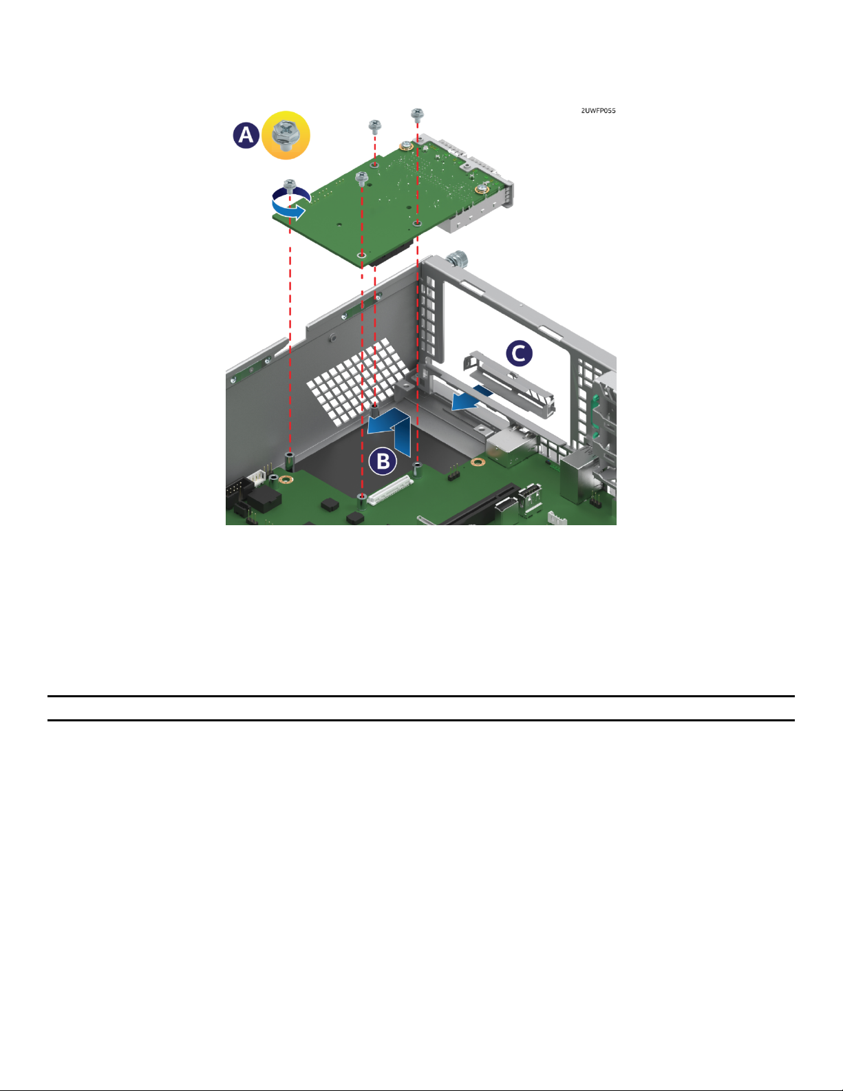
Intel® Server System R2000WF Product Family System Integration and Service Guide
3.6.2 OCP Expansion Module Removal
Figure 85. OCP Expansion Module Removal
1. Power off the server and detach the power cable(s).
2. Detach all cables from the OCP Module.
3. Remove the system cover – (see Section 2.2.1).
4. Remove the four screws as shown (see Letter ‘A’).
5. Carefully pull up on the OCP Module until it disengages from the server board (see Letter ‘B’).
6. If no replacement module is to be installed, re-install the OCP bay filler panel (See letter ‘C’)
Note: The filler panel snaps into the back panel from the outside of the chassis.
74
Page 75
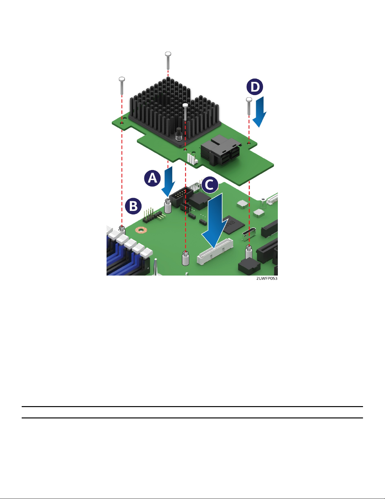
Intel® Server System R2000WF Product Family System Integration and Service Guide
3.7 Intel® SAS RAID Module Installation/Removal
3.7.1 Intel® SAS RAID Module Installation
Figure 86. Intel® SAS RAID Module Installation
1. Insert the four barrel standoffs into the matching holes in the server board (see Letter ‘A’).
2. Align the module mounting holes over the four barrel standoffs (see Letter ‘B’).
3. Press down firmly until the module connector is fully engaged with the matching connector on the
server board and the module is firmly seated over each barrel standoff (see Letter ‘C’).
4. Insert a locking pin into each barrel standoff and connect cables (see Letter ‘D’).
3.7.2 Intel® SAS RAID Module Removal
1. Disconnect cables and remove the four locking pins from each barrel standoff.
2. Grasp the module near the front two barrel standoffs and pull up firmly until the front side of the
module is clear of the standoffs.
3. Repeat step 2 to release the other side of the module.
Note: Remember to remove the four plastic barrel standoffs when replacing the server board.
75
Page 76

Intel® Server System R2000WF Product Family System Integration and Service Guide
3.8 Intel® RAID Maintenance Free Backup Unit (RMFBU) – Mounting Bracket
Installation
Figure 87. Intel® RMFBU Installation
1. Remove the RMFBU mounting bracket from the system accessory kit.
2. Place the RMFBU bracket onto the air duct (see Letter ‘A’).
3. Secure the RMFBU bracket to the air duct using the four screws (see Letter ‘B’).
4. Slide and lock the RMFBU onto the mounting bracket (see Letter ‘C’).
76
Page 77
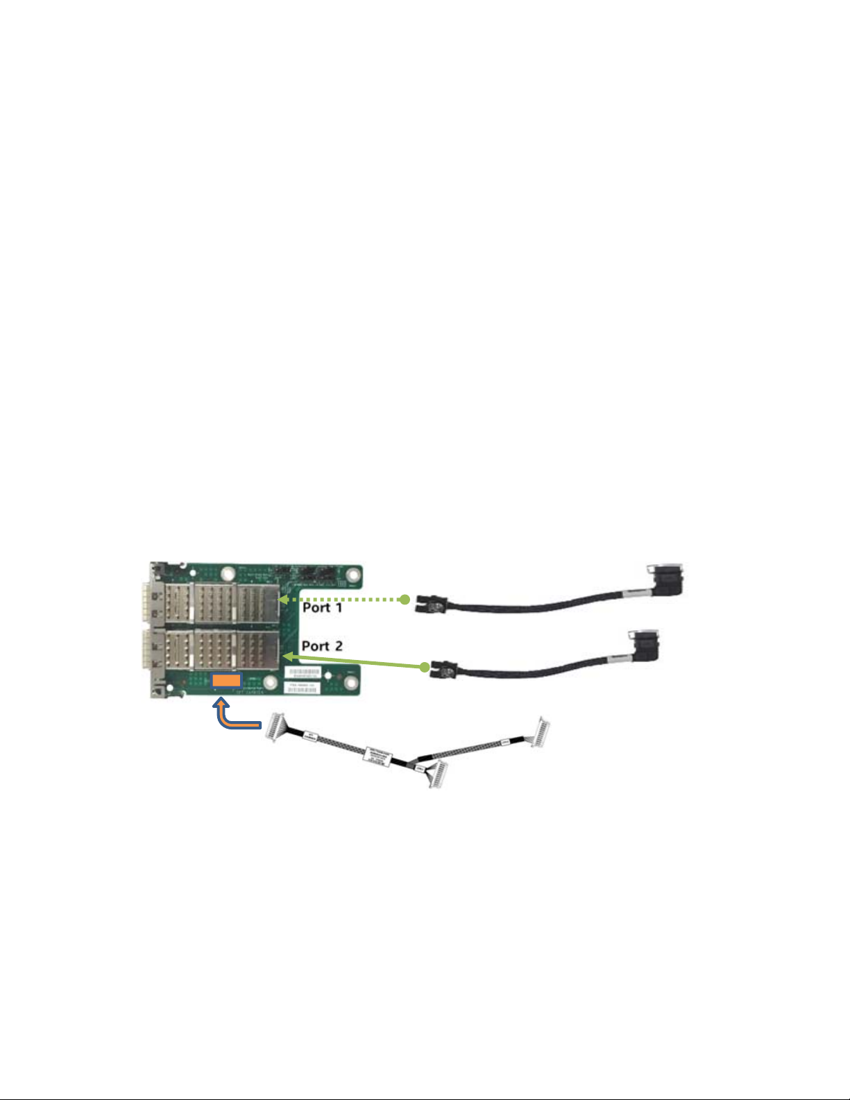
Intel® Server System R2000WF Product Family System Integration and Service Guide
–
–
3.9 Intel® Omni-Path IFT Carrier Accessory Kit Installation
The Intel® Server System R2000WF product family has support for 1 or 2 Intel® Xeon® processor Scalable
family SKUs that include an Intel Omni-path Host Fabric Interface (HFI) connector. In support of these
processor SKUs, one of two available Intel accessory kits is necessary to enable support for the fabric
interface.
AWF1PFABKITM – Intel Omni-path IFT Carrier Kit – Mezzanine Card
AWF1PFABKITP – Intel Omni-path IFT Carrier Kit – PCIe Add-in Card
The following sections describe the installation of components included with each kit.
3.9.1 Intel® Omni-path IFT Carrier Kit (iPC AWF1PFABKITM) – Installation
Kit Contents:
1 – Dual port IFT Carrier Mezzanine Card
1 – Internal Host Fabric Interface (HFI) Cable (CPU1)
1 – Internal Omni-Path Sideband Cable
2 – Fabric Processor Carrier Clips
Intel Cable Kit AXXCBL235IFPL1
required for dual fabric processor configurations.
1. Install Fabric processor(s) on to the server board. See Section 2.5 for processor assembly and installation
instructions.
Internal HFI Cable
IFT Card to CPU #1
B
C - Optional
Internal HFI Cable
IFT Card to CPU #2
A
Omni-path Sideband Cable
Figure 88. IFT Carrier Mezzanine Card Assembly
2. Connect the internal Omni-path sideband cable to the matching connector on the IFT Carrier mezzanine
card (See letter “A”)
3. Insert the internal HFI cable to Port 1 of the IFT Carrier mezzanine card until it locks into place (See letter
“B”)
4. (Optional – For dual Fabric processor configurations) Insert the second internal HFI cable to Port 2 of the
IFT Carrier mezzanine card until it locks into place (See letter “C”)
77
Page 78

Intel® Server System R2000WF Product Family System Integration and Service Guide
Figure 89. IFT Mezzanine Card Installation
5. Remove the OCP bay filler from the chassis back panel. Squeeze the panels on each side of the filler and
push it out from the chassis.
6. Remove the four (4) pre-installed screws from the mounting stand-offs (2 on the server board + 2 on the
chassis base)
7. Carefully angle and insert the rear connectors of the IFT Carrier card into the cut-out on the chassis back
panel and position the card over the four stand-offs on the server board (see Letter ‘A’). Care should be
taken NOT to damage the I/O shield material when placing the card into the back panel cut-out
8. Secure the IFT Carrier card with four screws (see Letter ‘B’). Tightened to 8 in-lb
9. Route the HFI cable attached to Port 1 of the IFT Carrier Card to CPU #1
Place and Insert Cable
Lock Cable
Figure 90. Fabric Processor Cable Installation
10. Place the HFI cable processor connector within the connector rails on the processor socket and slide
processor and cable connectors together (See Letter A)
78
Page 79
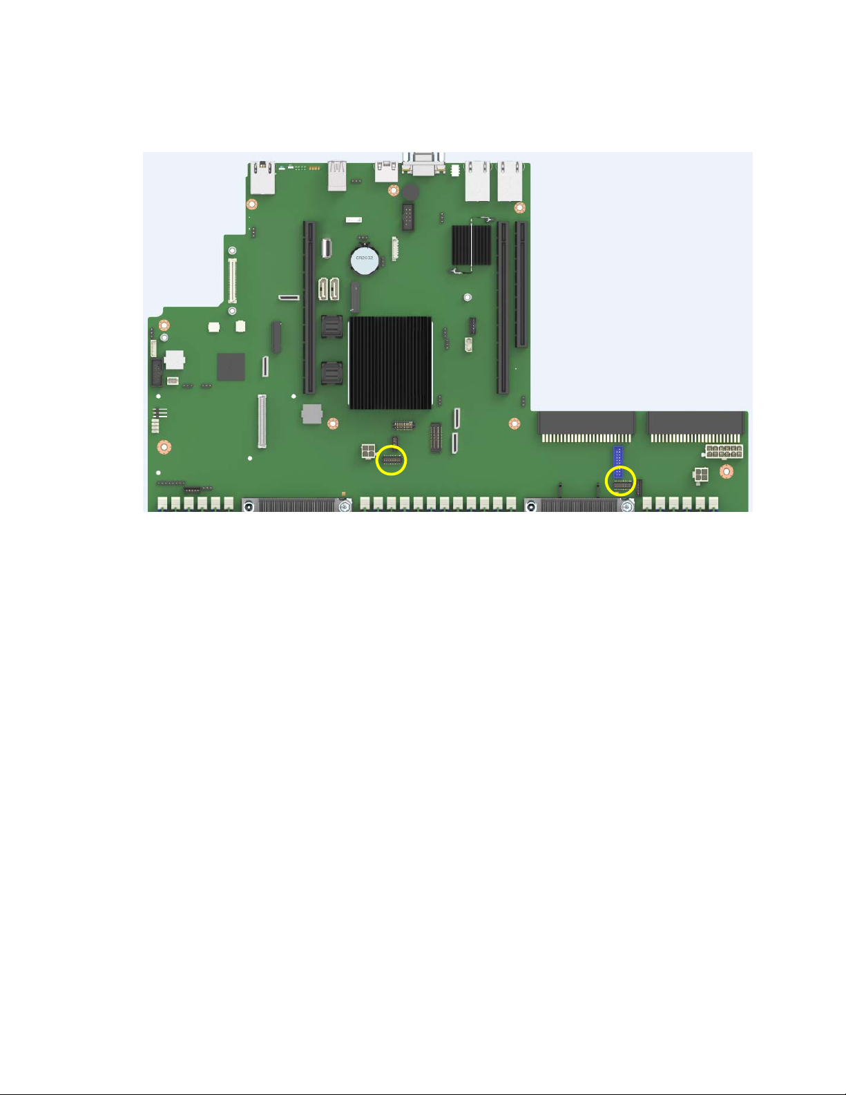
Intel® Server System R2000WF Product Family System Integration and Service Guide
r
r
11. Pull the bail wire back until the cable is securely locked in place (See Letter B)
12. Repeat Steps 8 thru 10 for the second internal HFI cable if present
Omni-path Sideband Connecto
CPU #1
Omni-path Sideband Connecto
CPU #2
Figure 91. Onboard Omni-path Sideband Signal Connectors
13. Connect the Omni-path sideband cable from the IFT Carrier card to the two sideband signal connectors
on the server board at the locations shown above.
3.9.2 Intel® Omni-path IFT Carrier Kit (iPC AWF1PFABKITP) – Installation
Kit Contents:
1 – Dual port IFT Carrier PCIe Add-in Card
1 – Internal Host Fabric Interface (HFI) Cable (CPU1)
1 – Internal Omni-Path Sideband Cable
2 – Fabric Processor Carrier Clips
Intel Cable Kit AXXCBL370IFPS1 required for dual fabric processor configurations.
1. Install Fabric processor(s) on to the server board. See Section 2.5 for fabric processor assembly and
installation instructions.
79
Page 80

Intel® Server System R2000WF Product Family System Integration and Service Guide
–
–
Omni-path Sideband Cable
A
Internal HFI Cable
IFT Card to CPU #1
B
C - Optional
Internal HFI Cable
Figure 92. IFT Carrier Add-in Card Assembly
2. Connect the internal Omni-path sideband cable to the matching connector on the IFT Carrier card (See
letter “A”)
3. Insert the internal HFI cable to Port 1 of the IFT Carrier mezzanine card until it locks into place (See letter
“B”)
4. (Optional – For dual Fabric processor configurations) Insert the second internal HFI cable to Port 2 of the
IFT Carrier card until it locks into place (See letter “C”)
IFT Card to CPU #2
Figure 93. IFT Carrier Add-in Card Installation
5. Remove the desired riser bracket assembly from the system and install the IFT Carrier card to one of the
add-in card slots on the riser card
6. Re-install the riser bracket in to the server – See section 2.9.3
7. Route the HFI cable attached to Port 1 of the IFT Carrier Card to CPU #1
80
Page 81

Intel® Server System R2000WF Product Family System Integration and Service Guide
r
r
Place and Insert Cable
Lock Cable
Figure 94. Fabric Processor Cable Installation
8. Place the HFI cable processor connector within the connector rails on the processor socket and slide
processor and cable connectors together (See Letter A)
9. Pull the bail wire back until the cable is securely locked in place (See Letter B)
10. Repeat Steps 7 thru 9 for the second internal HFI cable if present
Omni-path Sideband Connecto
CPU #1
Omni-path Sideband Connecto
CPU #2
11. Connect the Omni-path sideband cable from the IFT Carrier card to the two sideband signal connectors
on the server board at the locations shown above.
81
Page 82

Intel® Server System R2000WF Product Family System Integration and Service Guide
3.10 2 x 2.5” Rear Mount Backplane Module Accessory Kit (iPC- A2UREARHSDK1)
Figure 95. 2 x 2.5" Rear Mount Backplane Module Installation
1. Remove the two screws securing the bay cover plate to the chassis (see Letter ‘A’).
2. Unlatch and remove the bay cover plate from the chassis (see Letter ‘B’).
3. Carefully remove the backplane module from its packaging.
4. Position the drive bay module over the power supply bay and slide it back until it is flush with the back
of the chassis back panel (see Letter ‘C’).
5. Secure the drive bay module to the chassis using four screws; two on the chassis sidewall, and two on
the chassis back panel. (See Letter ‘D’).
6. From the backplane accessory kit, locate the following cables
Figure 96. Rear HSBP Power Cable
5-pin I2C to
Rear Backplane
3-pin I2C to
Server Board
Figure 97. Rear HSBP I2C Cable
82
Page 83

Intel® Server System R2000WF Product Family System Integration and Service Guide
7-pin SATA to
rear backplane
5-pin SATA SGPIO
to rear backplane
5-pin SATA SGPIO to
Server Board
7-pin SATA to
Server Board
Figure 98. Rear HSBP SATA & SGPIO Cable Bundle
Figure 99. Rear Backplane Cable Connectors
7. Connect the 2x3 power cable connector (labeled “SB”) to the server board “Peripheral PWR” connector.
8. Connect the 2x3 power cable connector (labeled “BP”) to the backplane “PWR” connector.
2
9. Connect the 5-pin I
C cable connector to the matching “HSBP_ I2C” connector on the backplane.
83
Page 84

Intel® Server System R2000WF Product Family System Integration and Service Guide
10. Connect the 3-pin I
2
C cable connector to the matching “HSBP_I2C” connector on the server board.
11. Match and connect the 7-pin SATA “Drive 0” and “Drive 1” cable connectors to the “Drive_0” and
“Drive_1” connectors on the backplane.
12. Connect the 5-pin SATA SGPIO cable connector to the “SGPIO” connector on the backplane.
13. Match and connect the 7-pin “SATA 4” and “SATA 5” cable connectors to the “sSATA_4” and “sSATA_5”
connectors on the server board.
14. Connect the 5-pin SATA SGPIO cable connector to the “SGPIO” connector on the server board.
84
Page 85

Intel® Server System R2000WF Product Family System Integration and Service Guide
3.11 Intel® SAS Expander Card Installation
Depending on the front drive bay configuration, 2.5” or 3.5” drive support, and drive type (6Gb/s SAS/SATA
or 12 Gb/s SAS), the 2U server system can support different Intel® SAS Expander card options.
3.11.1 2.5” Front Drive Bay Support
For Intel® Server Systems supporting 2.5” drive carriers, an Intel® SAS Expander Mezzanine Card option is
mounted internally behind the front drive bays.
Intel product code: RES3TV360 (12Gb)
Figure 100. SAS Expander Mezzanine Card Installation
1. Locate the Intel SAS RAID Expander Mezzanine Card.
2. Remove the system cover (see Section 2.2.1).
3. Remove the air duct (see Section 2.3.1).
4. Remove the system fan module (see Section 2.4.1).
5. Attach the rubber bumpers to the white circle targets on the bottom side of the RAID Expander card.
6. Align the three screw holes of the RAID Expander card with the matching threaded holes on the base of
the chassis directly behind the front drive bays (see Letter ‘A’).
7. Secure the RAID Expander card to the chassis using three screws (8 in/lb torque for each screw)(see
Letter ‘B’).
8. Locate and remove the power splitter cable from the RAID Expander kit.
9. Attach the power splitter cable to the power cable designated for use on the middle drive bay module.
10. Attach the 1x4-pin power connector from the splitter cable to the RAID Expander card.
11. Attach the 2x2-pin power connector from the splitter to the middle hot swap backplane.
85
Page 86

Intel® Server System R2000WF Product Family System Integration and Service Guide
3.11.2 3.5” Front Drive Bay Support
For the Intel® Server Systems supporting 3.5” drive carriers, an Intel® SAS Expander PCIe* add-in card option
installs into any available PCIe* add-in card slot. See section 2.9
Intel product code - RES3FV288 (12Gb)
3.11.3 Intel® RAID Expander Card Cabling Overview
The following diagrams identify SAS Expander card connectors to be used when cabling the expander card
to the system backplane(s) and to the add-in SAS RAID card. Care should be taken when connecting cables
from the RAID expander card to the connectors on the backplane because each connector is preprogrammed at the factory to provide specific drive ID mapping. Improper connections may provide
undesirable drive mappings.
Figure 101. 12 Gb Intel® RAID Expander Card RES3FV288 Connector Identification
Figure 102. Internal 12 Gb Intel® RAID Expander Card RES3TV360 - Connector Identification Block
Diagram
86
Page 87

Intel® Server System R2000WF Product Family System Integration and Service Guide
3.12 R2208WF Upgrade to 16 Drive Configuration
The 8 x 2.5” drive R2208WF server system can be upgraded to a 16 x 2.5” drive system with the addition of
one 8 x 2.5” Front Drive Bay Module accessory kit option. Below is an installation overview. Refer to Section
1.3.1 for complete installation instructions.
Depending on the system configuration requirements, it may also be necessary to install an Intel® SAS
expander card. See Section 3.11.1 for SAS Expander card installation instructions.
87
Page 88

Intel® Server System R2000WF Product Family System Integration and Service Guide
3.13 24 Drive Upgrade Option
The “no drive” server chassis building block SKU and any 2.5” drive server system can be configured to
support 24 drives.
Upgrade
In order to support 24 2.5” drives, the system must have all the following Intel accessory kits installed:
• Three (3) 8 x 2.5” Front Drive Bay Module Accessory Kit options (several kits available)
• Storage Rack Handles from Rack Handle Spare / Accessory Kit (Intel product code A2UHANDLKIT)
• Appropriate SAS/SATA/NVMe Cables
• (Optional) Intel® SAS (12Gb) Expander Card (Intel product code RES3TV360)
Note: Reference the Intel® Server S2600WF Product Family Configuration Guide for a complete list of
available accessory options
1. Remove the system cover (see Section 2.2.1).
2. Remove the air duct (see Section 2.3.1).
3. Remove the system fan module (see section 2.4.1).
4. Disconnect the front panel cables for the Front USB ports, Front Video port, and Front Control Panel
from the server board (see Figure 12).
5. Disconnect all cables from the first (left most) drive bay module.
6. Remove the standard rack handles
Figure 103. Standard Rack Handle Removal
88
Page 89

Intel® Server System R2000WF Product Family System Integration and Service Guide
7. Remove the following from the chassis: drive bay retention bracket, drive bay modules (Storage and I/O)
and/or drive bay inserts.
Drive Bay Storage Module
Drive Bay Insert
Drive Bay I/O Module
Figure 104. Drive Bay Disassemly – Retention Bracket Removal
a) Remove the 6 screws from the top front edge of the drive bay (See Letter ‘A’) and pull out the metal
retention bracket (see Letter ‘B’).
b) Remove the top screws near the back edge of the drive bay from all installed drive bay modules (see
Letter ‘C’).
c) Carefully place the chassis on its side.
89
Page 90
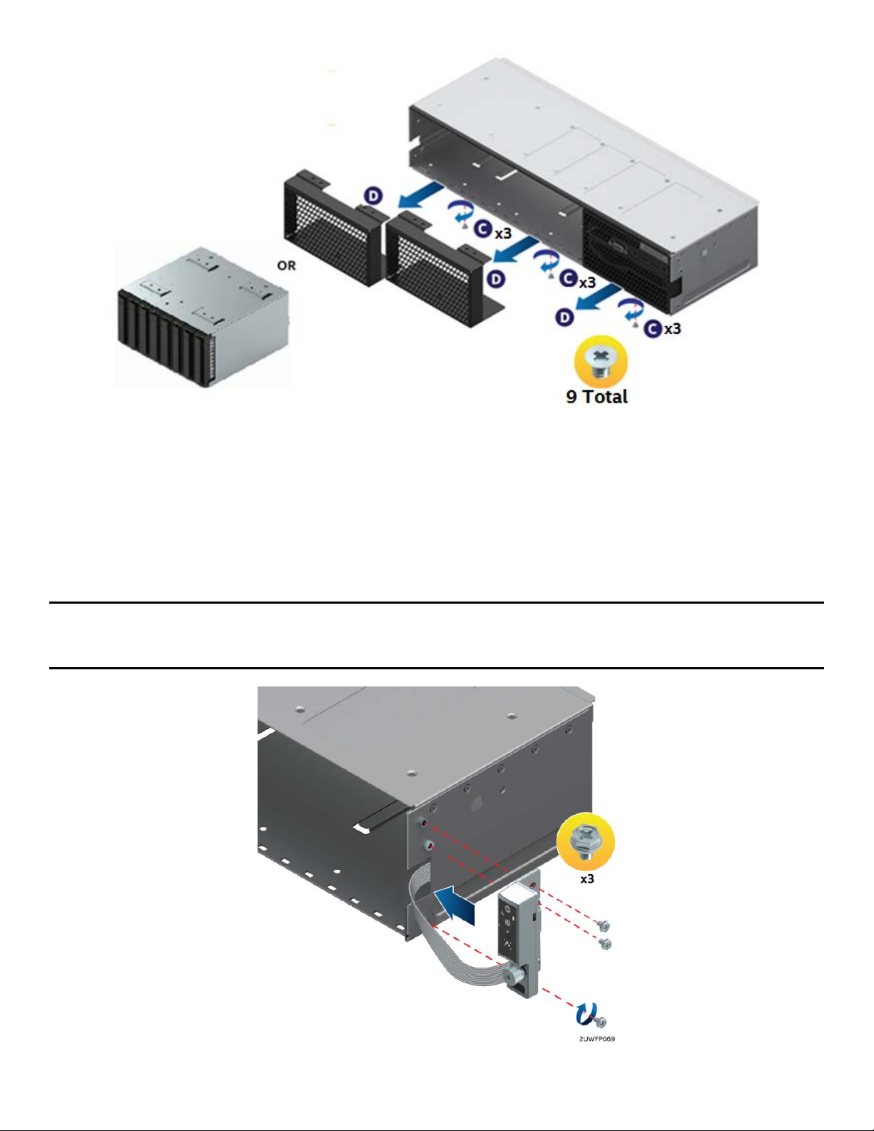
Intel® Server System R2000WF Product Family System Integration and Service Guide
Figure 105. Drive Bay Disassembly – Module Removal
d) From the bottom of the chassis, remove three (3) screws from each installed drive bay module or
insert (see Letter ‘C’’).
e) Carefully return the chassis to its original position.
f) Carefully slide out each drive bay module (Storage and I/O) and/or bay insert from the chassis (see
Letter ‘D’)
8. Install the Storage Rack Handles
Note: The Storage Rack Handles are ONLY intended to ease sliding of the system in and out of the rack
when a rail kit is installed on the system. The rack handles are NOT designed to support the full weight of the
system during installation/deinstallation or movement outside of the rack.
Figure 106. Storage Rack Handle Installation
90
Page 91

Intel® Server System R2000WF Product Family System Integration and Service Guide
a) Locate and remove the Left (with USB port) and Right (with Control Panel) storage rack handle
assemblies from Intel Accessory Kit A2UHANDLKIT.
b) Lay each rack handle assembly near the left and right chassis corners, then route the ribbon cable
from each along the inside of the chassis side wall towards the back of the drive bay.
c) Attach the left and right rack handle assemblies to the chassis using three screws each (8 in/lb
torque for each screw). Note that the ribbon cables should fit inside cutouts in the chassis sidewall.
Figure 107. Server Board USB 2.0 Header
d) Attach the Left USB flat cable to the black 10-pin server board connector labeled “FP_USB”.
e) Attach the Right front panel ribbon cable to the high density 30-pin connector labeled “Storage_FP”
on the front right corner of the server board.
f) Ensure that the ribbon cables are routed within the cable channel inside each chassis sidewall, then
secure them in place using the included adhesive tape strips.
Note: Failing to secure each ribbon cable to the chassis sidewall may cause cable damage
9. Install the 8 x 2.5” Drive Bay Module(s)
Figure 108. Installing the 8 x 2.5” Drive Bay Module(s)
91
Page 92

Intel® Server System R2000WF Product Family System Integration and Service Guide
a) Slide all 8x2.5” drive bay module(s) into the chassis (see Letter ‘E’).
b) Secure the top side of each drive bay module with two fastener screws each (see letter ‘F’) (8 in/lb
torque for each screw).
c) Carefully place the chassis on its side and secure the bottom side of each drive bay module with
three (3) screws each (see Letter ‘G’) (8 in/lb torque for each screw).
d) Carefully return the chassis to its original position.
10. Install Drive Bay Retention Bracket
Figure 109. Installing Drive Bay Retention Bracket
a) Locate the drive bay retention bracket and screws.
b) Carefully slide the drive bay retention bracket into the gap between the top of the drive bay
module(s) and the bottom of the drive bay sheet metal. (See Letter ‘A’).
c) Secure the retention bracket with six fastener screws (see Letter ‘B’). (8 in/lb torque for each screw).
d) Connect a power cable to each of the hot swap backplanes.
e) (Optional) Install add-in RAID Card option(s)
f) (Optional) Install SAS Expander module option – See Section 3.11.1
g) (Optional) Install SAS RAID RMFBU option(s)
h) Route and attach appropriate SAS/SATA/NVMe data cables between data I/O sources (SAS RAID,
Tri-Mode, onboard OCuLink, PCIe Switch) and backplanes
Note: If installing a RAID expander card, do NOT attach the power cable to the middle hot swap backplane.
This will be attached at a later time.
92
Page 93

Intel® Server System R2000WF Product Family System Integration and Service Guide
4. System Software Updates and Configuration
4.1 Updating the System Software Stack
The system includes a software stack to operate including a BIOS, BMC firmware, ME firmware, and FRU &
SDR data. A default software stack is loaded during the system manufacturing process. However, it may not
be the latest available. For best operation and system reliability, it is highly recommended to update the
system software stack to the latest available.
The latest system software stack can be downloaded from Intel at the following Intel web site:
http://downloadcenter.intel.com
At a minimum, after the initial configuration, the system’s FRU and SDR data MUST be updated to ensure that
the embedded platform management sub-system is configured properly. The system’s FRU and SDR data is
updated by running the FRUSDR utility. Properly loaded FRU and SDR data allows platform management to
monitor the appropriate system sensors which are used to determine proper system cooling, best
performance, and accurate error reporting. The FRUSDR utility is included in the platform’s System Update
Package (SUP) which can be downloaded from the Intel web site referenced above. The SUP will include full
system update instructions.
4.2 Using the BIOS Setup Utility
This section describes how to access and navigate the embedded <F2> BIOS Setup utility. This utility can be
used to view and configure system settings that determine how the server operates.
4.2.1 Entering BIOS Setup
To enter the BIOS Setup using a keyboard (or emulated keyboard), press the <F2> function key during boot
when the OEM or Intel Logo Screen or the POST Diagnostic Screen is displayed.
Note: At initial system power on, a USB Keyboard will not be functional until the USB Controller has been
initialized during the power on self test (POST) process. When the USB controller is initialized, the system
will beep once. Only after that time will the key strokes from a USB Keyboard be recognized allowing for
access into the <F2> BIOS Setup utility.
The following message will be displayed on the Diagnostic Screen or under the Quiet Boot Logo Screen:
Press <F2> to enter setup, <F6> Boot Menu, <F12> Network Boot
After pressing the <F2> key, the system will eventually load the BIOS Setup Utility and display the BIOS
Setup Main Menu screen.
Note: Should serious system errors occur during the POST process, the regular system boot will stop and the
system will load the BIOS Setup Utility and display the Error Manager Screen. The Error Manager Screen will
list and provide information about the specific boot errors detected
4.2.2 No Access to the BIOS Setup Utility
If the BIOS Setup Utility is not accessible by hitting the <F2> key or other described access methods, it may
be necessary to restore the BIOS default settings. For information relating to restoring BIOS defaults, see
Section 6.2.1 BIOS Default Jumper Block.
93
Page 94

Intel® Server System R2000WF Product Family System Integration and Service Guide
4.2.3 Navigating the BIOS Setup Utility
The BIOS Setup Utility consists of several menu screens, each holding either informational fields and/or
configurable system setup options.
The bottom right portion of each menu screen provides a list of commands that are used to navigate through
the Setup utility. These commands are displayed at all times.
If no Administrator or User password is used, all available settings are configurable and can be set by anyone
with access to BIOS Setup.
System settings that are not configurable, because of security settings or configuration limits, will be grayed
out and are not accessible.
Table 3. BIOS Setup: Keyboard Command Bar
Key
<Enter>
<Esc>
↑
↓
← →
<Tab>
−
Option Description
Execute Command
Exit
Select Item
Select Item
Select Menu
Select Field
Change Value
The <Enter> key is used to activate submenus when the
selected feature is a submenu, or to display a pick list if a
selected option has a value field, or to select a subfield for
multi-valued features like time and date. If a pick list is
displayed, the <Enter> key selects the currently highlighted
item, undoes the pick list, and returns the focus to the parent
menu.
The <Esc> key provides a mechanism for backing out of any
field. When the <Esc> key is pressed while editing any field or
selecting features of a menu, the parent menu is re-entered.
When the <Esc> key is pressed in any submenu, the parent
menu is re-entered. When the <Esc> key is pressed in any
major menu, the exit confirmation window is displayed and the
user is asked whether changes can be discarded. If “No” is
selected and the <Enter> key is pressed, or if the <Esc> key is
pressed, the user is returned to where they were before <Esc>
was pressed, without affecting any existing settings. If “Yes” is
selected and the <Enter> key is pressed, the setup is exited and
the BIOS returns to the main System Options Menu screen.
The up arrow is used to select the previous value in a pick list,
or the previous option in a menu item's option list. The
selected item must then be activated by pressing the <Enter>
key.
The down arrow is used to select the next value in a menu
item’s option list, or a value field’s pick list. The selected item
must then be activated by pressing the <Enter> key.
The left and right arrow keys are used to move between the
major menu pages. The keys have no effect if a sub-menu or
pick list is displayed.
The <Tab> key is used to move between fields. For example,
<Tab> can be used to move from hours to minutes in the time
item in the main menu.
The minus key on the keypad is used to change the value of
the current item to the previous value. This key scrolls through
the values in the associated pick list without displaying the full
list.
94
Page 95

Intel® Server System R2000WF Product Family System Integration and Service Guide
Key
+
<F9>
Option Description
Change Value
Setup Defaults
The plus key on the keypad is used to change the value of the
current menu item to the next value. This key scrolls through
the values in the associated pick list without displaying the full
list. On 106-key Japanese keyboards, the plus key has a
different scan code than the plus key on the other keyboards,
but will have the same effect.
Pressing the <F9> key causes the following to display:
Load Optimized Defaults?
Yes No
If “Yes” is highlighted and <Enter> is pressed, all Setup fields are
set to their default values. If “No” is highlighted and <Enter> is
pressed, or if the <Esc> key is pressed, the user is returned to
where they were before <F9> was pressed without affecting any
existing field values.
Pressing the <F10> key causes the following message to
display:
Save configuration and reset?
Yes No
<F10>
Save and Exit
If “Yes” is highlighted and <Enter> is pressed, all changes are saved
and the Setup is exited. If “No” is highlighted and <Enter> is
pressed, or the <Esc> key is pressed, the user is returned to where
they were before <F10> was pressed without affecting any existing
values.
95
Page 96

Intel® Server System R2000WF Product Family System Integration and Service Guide
5. System Packaging Assembly Instructions
The original Intel packaging in which the server system was delivered, is designed to provide protection to a
fully configured system and was tested to meet ISTA (International Safe Transit Association) Test Procedure
3A (2008). The packaging was also designed to be re-used for shipment after system integration has been
completed.
The original packaging includes two layers of boxes – an inner box and the outer shipping box, and various
protective inner packaging components. The boxes and packaging components are designed to function
together as a protective packaging system. When reused, all of the original packaging material must be used,
including both boxes and each inner packaging component. In addition, all inner packaging components
MUST be reinstalled in the proper location to ensure adequate protection of the system for subsequent
shipment.
Note: The design of the inner packaging components does not prevent improper placement within the
packaging assembly. There is only one correct packaging assembly that will allow the package to meet the
ISTA (International Safe Transit Association) Test Procedure 3A (2008) limits.
Failure to follow the specified packaging assembly instructions may result in damage to the system during
shipment.
1. Place four foam inserts into the inner box as shown. Note foam insert orientation.
2. Place the Accessory Kit box between the end foam insert and the end wall of the inner box as shown.
96
Page 97

Intel® Server System R2000WF Product Family System Integration and Service Guide
3. Place the two pieces of side wall foam as shown.
4. Place three corrugated double wall cardboard pads onto the two bottom foam inserts as shown.
5. Carefully place the system into the shipping bag and tape the bag shut.
6. Carefully lower the system into the inner shipping box as shown.
97
Page 98

Intel® Server System R2000WF Product Family System Integration and Service Guide
7. Place the accesory box next to the foam located in the back of the box.
8. Place foam in front of the accessory box.
98
Page 99

Intel® Server System R2000WF Product Family System Integration and Service Guide
9. At the front of the system, between the front foam insert and system front panel, place the foam
marked J36266-001.
10. Place two remaining foam inserts on top of the cardboard panels in the positions shown.
99
Page 100

Intel® Server System R2000WF Product Family System Integration and Service Guide
11. Fold the top flaps of the inner box closed, end flaps first, followed by side flaps.
a. By design, the two side flaps will not meet. Do not tape side flaps shut.
12. Fold the top flaps of the outer box closed, end flaps first, followed by the side flaps.
13. Tape the outer box using an H-pattern. Across the center first, followed by both ends.
100
 Loading...