

Page 1

Intel® Server System R2000WF
Product Family
Technical Product Specification
An overview of product features, functions, architecture, and support specifications
Revision 1.2
November 2017
Intel® Server Products and Solutions
Page 2

<Blank page>
Page 3

Intel® Server System R2000WF Product Family Technical Product Specification
Date
Revision
Modifications
July 2017
1.0
Production Release
September
1.1
Updated all tables from Appendix B and Appendix C
Updated S2600WF Architecture Block Diagram
Added QAT information:
Server Board Product Family Feature Set
S2600WFQ Architecture Block Diagram
Edited bullet on the section 4.1.1 Memory Slot Population Requirements
Added subsection 3.3.8 DC Output Specification
November 2017
1.2
Updated Trusted Platform Module (China version) iPC AXXTPMCHNE8 on table Intel® Server
Board S2600WF product family feature set
Added TPM definition on Glossary section
Added Retimer accessory to the sections: 6.5, 7.4 and 7.4.4
Document Revision History
3
Page 4

Intel® Server System R2000WF Product Family Technical Product Specification
Disclaimers
Intel technologies’ features and benefits depend on system configuration and may require enabled
hardware, software, or service activation. Learn more at Intel.com, or from the OEM or retailer.
You may not use or facilitate the use of this document in connection with any infringement or other legal
analysis concerning Intel products described herein. You agree to grant Intel a non-exclusive, royalty-free
license to any patent claim thereafter drafted which includes subject matter disclosed herein.
No license (express or implied, by estoppel or otherwise) to any intellectual property rights is granted by this
document.
The products described may contain design defects or errors known as errata which may cause the product
to deviate from published specifications. Current characterized errata are available on request.
Intel disclaims all express and implied warranties, including without limitation, the implied warranties of
merchantability, fitness for a particular purpose, and non-infringement, as well as any warranty arising from
course of performance, course of dealing, or usage in trade.
Copies of documents which have an order number and are referenced in this document may be obtained by
calling 1-800-548-4725 or by visiting www.intel.com/design/literature.htm.
Intel, the Intel logo, and Xeon are trademarks of Intel Corporation or its subsidiaries in the U.S. and/or other
countries.
*Other names and brands may be claimed as the property of others.
Copyright © Intel Corporation. All rights reserved.
4
Page 5

Intel® Server System R2000WF Product Family Technical Product Specification
Table of Contents
1. Introduction ............................................................................................................................................................... 15
1.1 Document Outline.......................................................................................................................................................... 16
1.2 Intel® Server Board Use Disclaimer......................................................................................................................... 16
1.3 Product Errata.................................................................................................................................................................. 16
2. Server System Family Overview............................................................................................................................ 17
2.1 System Features Overview ......................................................................................................................................... 21
2.2 Server Board Architecture .......................................................................................................................................... 22
2.3 Server Board Features Overview ............................................................................................................................. 24
2.4 Back Panel Features ...................................................................................................................................................... 27
2.5 Front Control Panel Options ..................................................................................................................................... 27
2.6 Front Drive Bay Options .............................................................................................................................................. 28
2.7 Locking Front Bezel Support ..................................................................................................................................... 29
2.8 System Dimensional Data ........................................................................................................................................... 30
2.8.1 Chassis Dimensions, 2.5” Drive Bay ........................................................................................................................ 30
2.8.2 Label Emboss Dimensions ......................................................................................................................................... 31
2.8.3 Pull-Out Tab Label Emboss Dimensions.............................................................................................................. 32
2.9 System Cable Routing Channels .............................................................................................................................. 33
2.10 Available Rack and Cabinet Mounting Kit Options .......................................................................................... 34
2.11 System Level Environmental Limits ....................................................................................................................... 35
2.12 System Packaging .......................................................................................................................................................... 36
3. System Power ............................................................................................................................................................ 37
3.1 Power Supply Configurations ................................................................................................................................... 37
3.2 Power Supply Module Options ................................................................................................................................ 38
3.2.1 Power Supply Module Efficiency ............................................................................................................................. 38
3.2.2 Power Supply Module Mechanical Overview ..................................................................................................... 39
3.2.3 Power Cord Specification Requirements ............................................................................................................. 41
3.3 AC Power Supply Input Specifications .................................................................................................................. 41
3.3.1 Power Factor .................................................................................................................................................................... 42
3.3.2 AC Input Voltage Specification ................................................................................................................................. 42
3.3.3 AC Line Isolation Requirements ............................................................................................................................... 42
3.3.4 AC Line Dropout/Holdup ............................................................................................................................................ 42
3.3.5 AC Line Fuse ..................................................................................................................................................................... 43
3.3.6 AC Inrush ........................................................................................................................................................................... 43
3.3.7 AC Line Transient Specification ............................................................................................................................... 43
3.3.8 Susceptibility Requirements ...................................................................................................................................... 44
3.3.9 Electrostatic Discharge Susceptibility ................................................................................................................... 44
3.3.10 Fast Transient/Burst...................................................................................................................................................... 44
3.3.11 Radiated Immunity ........................................................................................................................................................ 44
3.3.12 Surge Immunity ............................................................................................................................................................... 44
3.3.13 Power Recovery .............................................................................................................................................................. 45
5
Page 6

Intel® Server System R2000WF Product Family Technical Product Specification
3.3.14 Voltage Interruptions ................................................................................................................................................... 45
3.3.15 Protection Circuits ......................................................................................................................................................... 45
3.3.16 Power Supply Status LED ........................................................................................................................................... 46
3.4 DC Power Supply Input Specifications (iPC – AXX750DCCRPS) ................................................................ 46
3.4.1 DC Input Voltage ............................................................................................................................................................ 46
3.4.2 DC Input Fuse................................................................................................................................................................... 47
3.4.3 DC Inrush Current .......................................................................................................................................................... 47
3.4.4 DC Input under Voltage ............................................................................................................................................... 47
3.4.5 DC Holdup Time and Dropout .................................................................................................................................. 47
3.4.6 DC Line Surge Voltages (Line Transients) ............................................................................................................ 47
3.4.7 Susceptibility Requirements ...................................................................................................................................... 48
3.4.8 Protection Circuits ......................................................................................................................................................... 48
3.5 Cold Redundancy Support ......................................................................................................................................... 49
3.5.1 Powering on Cold Standby Supplies to Maintain Best Efficiency .............................................................. 49
3.5.2 Powering on Cold Standby Supplies during a Fault or Over Current Condition ................................. 50
3.5.3 BMC Requirements ........................................................................................................................................................ 50
3.5.4 Power Supply Turn on Function .............................................................................................................................. 50
3.6 Closed Loop System Throttling (CLST) ................................................................................................................. 50
3.7 Smart Ride Through (SmaRT) ................................................................................................................................... 51
3.8 Server Board Power Connectors ............................................................................................................................. 51
3.8.1 Power Supply Module Card Edge Connector ..................................................................................................... 51
3.8.2 Optional 12 V Power Connectors for High Power Add-in Cards ............................................................... 51
3.8.3 Hot Swap Backplane Power Connector ................................................................................................................ 52
3.8.4 Peripheral Power Connector ..................................................................................................................................... 53
4. Thermal Management ............................................................................................................................................. 54
4.1 Thermal Operation and Configuration Requirements .................................................................................... 56
4.1.1 Memory Slot Population Requirements ............................................................................................................... 57
4.2 Thermal Management Overview .............................................................................................................................. 58
4.2.1 Fan Speed Control ......................................................................................................................................................... 59
4.3 System Fans ..................................................................................................................................................................... 62
4.4 Power Supply Module Fans ....................................................................................................................................... 64
4.5 FRUSDR Utility ................................................................................................................................................................. 64
5. Intel® Xeon Phi™ Coprocessor and Non-Intel GPGPU Add-in Card Support ............................................... 65
5.1 Support Criteria .............................................................................................................................................................. 65
5.2 Intel® Xeon Phi™ Coprocessor Card – System Configuration Requirements ......................................... 68
6. System Storage and Peripheral Drive Bay Overview ........................................................................................ 69
6.1 Front Mount – Drive Bay Support ............................................................................................................................ 69
6.2 Hot Swap Drive Carriers .............................................................................................................................................. 71
6.3 Peripheral Power Sources .......................................................................................................................................... 73
6.4 Hot Swap Backplane Support ................................................................................................................................... 73
6.4.1 SGPIO Functionality ...................................................................................................................................................... 75
6.4.2 I2C Functionality ............................................................................................................................................................. 75
6
Page 7

Intel® Server System R2000WF Product Family Technical Product Specification
6.5 8 x 2.5” Drive SATA/SAS/NVMe* Combo Backplane ....................................................................................... 75
6.6 8 x 2.5” Drive Dual Port SAS Backplane ................................................................................................................ 77
6.7 8 x 3.5” Drive Hot-Swap Backplane Overview.................................................................................................... 79
6.8 12 x 3.5” Drive Hot-Swap Backplane Overview ................................................................................................. 80
6.9 2 x 2.5” Hot Swap Drive Bay Accessory Kit .......................................................................................................... 81
6.10 Internal Fixed Mount Solid State Drive (SSD) Support ................................................................................... 85
7. Storage Controller Options Overview ................................................................................................................. 86
7.1 Onboard SATA Support .............................................................................................................................................. 86
7.1.1 Staggered Disk Spin-Up .............................................................................................................................................. 88
7.2 Onboard SATA Software RAID Support ............................................................................................................... 88
7.2.1 Intel® Rapid Storage Technology Enterprise (Intel® RSTe) 5.0 .................................................................... 89
7.2.2 Intel® Embedded Server RAID Technology 2 (ESRT2) 1.60 for SATA ...................................................... 89
7.3 M.2 SSD Support ............................................................................................................................................................ 91
7.3.1 Embedded RAID Support ........................................................................................................................................... 91
7.4 PCIe NVMe* Drive Support ......................................................................................................................................... 92
7.4.1 Onboard PCIe* OCuLink Connectors ..................................................................................................................... 92
7.4.2 Intel® Volume Management Device (Intel® VMD) for NVMe* ....................................................................... 92
7.4.3 Intel® Virtual RAID on Chip (Intel® VROC) for NVMe* ...................................................................................... 96
7.4.4 NVMe* Drive Population Rules for Intel® VROC ................................................................................................ 97
7.5 Intel® Integrated RAID Module Support ............................................................................................................. 101
7.5.1 RAID Maintenance Free Backup Unit (AXXRMFBUx) Support .................................................................. 102
7.6 Intel® RAID Expander Card Support .................................................................................................................... 103
8. Front Control Panel and I/O Panel Overview ................................................................................................... 107
8.1 I/O Panel Features ...................................................................................................................................................... 107
8.2 Control Panel Features ............................................................................................................................................. 108
9. PCIe* Riser Card Support ...................................................................................................................................... 111
9.1 Riser Card Assembly .................................................................................................................................................. 112
9.2 Riser Slot #1 and Riser Slot #2 Riser Card Options ...................................................................................... 114
9.2.1 Three-Slot PCIe Riser Card (iPC – A2UL8RISER2) ......................................................................................... 114
9.2.2 Two-Slot PCIe Riser Card (iPC – A2UL16RISER2) .......................................................................................... 114
9.3 Riser Slot #3 Riser Card Option (iPC – A2UX8X4RISER) ............................................................................. 115
10. OCP* Compatible Intel® Ethernet Network Adapter Support ....................................................................... 116
11. Basic and Advanced Server Management Features ........................................................................................ 117
11.1 Dedicated Management Port ................................................................................................................................. 118
11.2 Embedded Web Server ............................................................................................................................................. 118
11.3 Advanced Management Feature Support (Intel® RMM4 Lite) ................................................................... 120
11.3.1 Keyboard, Video, Mouse (KVM) Redirection .................................................................................................... 120
11.3.2 Remote Console .......................................................................................................................................................... 121
11.3.3 Performance .................................................................................................................................................................. 121
11.3.4 Availability ...................................................................................................................................................................... 122
11.3.5 Security ............................................................................................................................................................................ 122
11.3.6 Usage ................................................................................................................................................................................ 122
7
Page 8

Intel® Server System R2000WF Product Family Technical Product Specification
11.3.7 Force-enter BIOS Setup ........................................................................................................................................... 122
11.3.8 Media Redirection ....................................................................................................................................................... 122
Appendix A. Integration and Usage Tips .............................................................................................................. 124
Appendix B. POST Code Diagnostic LED Decoder ............................................................................................. 125
B.1. Early POST Memory Initialization MRC Diagnostic Codes ..................................................................... 126
B.2. BIOS POST Progress Codes .................................................................................................................................... 129
Appendix C. POST Code Errors .............................................................................................................................. 132
C.1. POST Error Beep Codes ........................................................................................................................................... 140
Appendix D. System Configuration Table for Thermal Compatibility ........................................................... 141
Appendix E. System Cable Routing Diagrams .................................................................................................... 158
Appendix F. Statement of Volatility...................................................................................................................... 163
Glossary ........................................................................................................................................................................... 166
8
Page 9

Intel® Server System R2000WF Product Family Technical Product Specification
List of Figures
Figure 1. System components overview.......................................................................................................................................... 21
Figure 2. 2U standard top cover ......................................................................................................................................................... 21
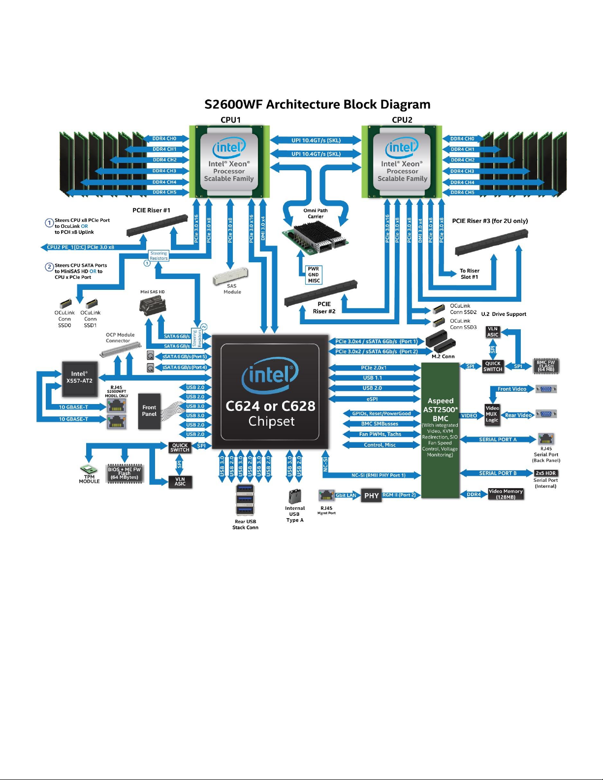
Figure 3. Server Board Architecture .................................................................................................................................................. 22
Figure 4. S2600WFQ Server Board Architecture ......................................................................................................................... 23
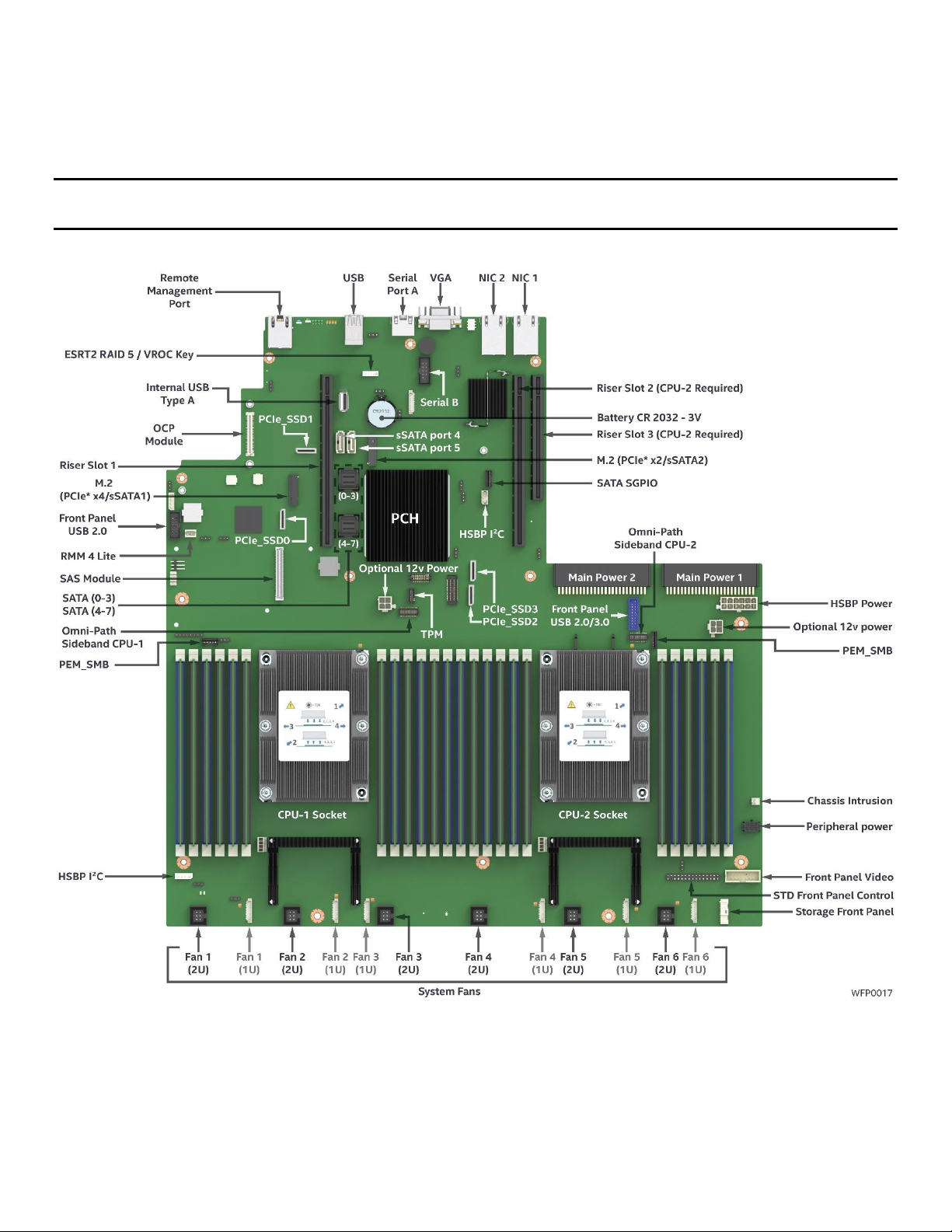
Figure 5. Server board component/feature identification ....................................................................................................... 24
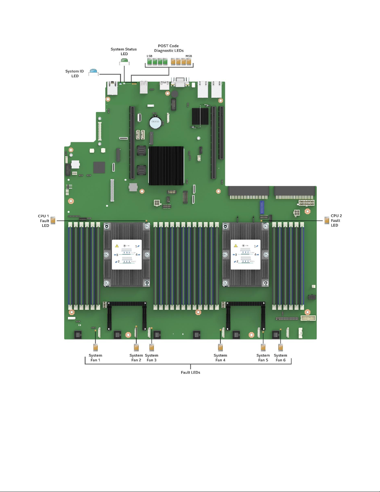
Figure 6. Intel® Light Guided Diagnostics – LED identification ............................................................................................... 25
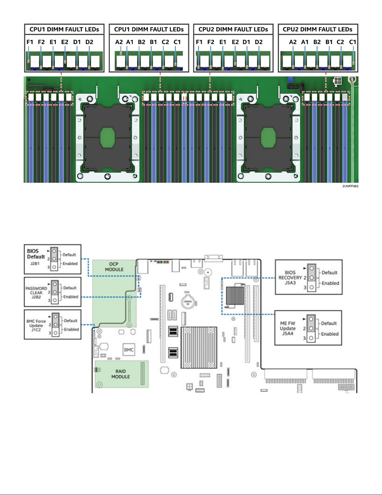
Figure 7. Intel® Light Guided Diagnostics - DIMM fault LEDs .................................................................................................. 26
Figure 8. System configuration and recovery jumpers ............................................................................................................. 26
Figure 9. Back panel feature identification ..................................................................................................................................... 27
Figure 10. Front control panel options ............................................................................................................................................ 27
Figure 11. 3.5" x 8 front drive bay configuration – R2308WFxxxx ....................................................................................... 28
Figure 12. 3.5" x 12 front drive bay configuration – R2312WFxxxx ..................................................................................... 28
Figure 13. 2.5" x 8 front drive bay configuration – R2208WFxxxx ....................................................................................... 28
Figure 14. 2.5" x 16 front drive bay configuration – R2208WFxxxx + 8 Drive Accessory Kit .................................... 28
Figure 15. 2.5" x 24 front drive bay configuration – R2224WFxxxx ..................................................................................... 28
Figure 16. Concept Reference Design – Front Bezel Installation .......................................................................................... 29
Figure 17. Chassis dimensions, 2.5” drive bay .............................................................................................................................. 30
Figure 18. Label emboss dimensions ............................................................................................................................................... 31
Figure 19. Pull-out tab label emboss dimensions, non-storage models........................................................................... 32
Figure 20. Pull-out tab label area dimensions, storage models ............................................................................................ 32
Figure 21. System cable routing channels...................................................................................................................................... 33
Figure 22. Power supply module identification ........................................................................................................................... 37
Figure 23. Power supply module mechanical overview ........................................................................................................... 39
Figure 24. 1100W AC power supply module mechanical drawing ...................................................................................... 40
Figure 25. 1300W AC power supply module mechanical drawing ...................................................................................... 40
Figure 26. AC power cord specification ........................................................................................................................................... 41
Figure 27. DC power cord specification ........................................................................................................................................... 41
Figure 28. Power cable for the OPT_12V ........................................................................................................................................ 52
Figure 29. System Airflow and Fan Identification ........................................................................................................................ 54
Figure 30. System DIMM/DIMM blanks for 8x2.5, 16x2.5, and 8x3.5 drive configurations ....................................... 57
Figure 31. System DIMM/DIMM blanks for 24x2.5 and 12x3.5 drive configurations ................................................... 57
Figure 32. High-level fan speed control model ............................................................................................................................ 62
Figure 33. Server board 2U system fan connector locations ................................................................................................. 62
Figure 34. System fan assembly ......................................................................................................................................................... 63
Figure 35. 2-slot PCIe* riser card ........................................................................................................................................................ 65
Figure 36. Auxiliary 12 V power cable (iPC – AXXGPGPUCABLE) ......................................................................................... 66
Figure 37. High airflow air duct included in accessory kit AWFCOPRODUCTAD ........................................................... 66
Figure 38. Shipping bracket .................................................................................................................................................................. 67
Figure 39. Shipping bracket placement ........................................................................................................................................... 68
Figure 40. 2.5" front mount drive bay, 8 drive (R2208WFxxx) and 16 drive configuration option ......................... 69
9
Page 10

Intel® Server System R2000WF Product Family Technical Product Specification
Figure 41. 2.5" front mount drive bay, 24 drive (R2224WFxxx) configuration ................................................................ 69
Figure 42. 3.5" drive bay, 8 drive configuration ........................................................................................................................ 70
Figure 43. 3.5” drive bay, 12 drive configuration ......................................................................................................................... 70
Figure 44. Drive carrier removal .......................................................................................................................................................... 71
Figure 45. 2.5" SSD mounted to 3.5" drive carrier....................................................................................................................... 71
Figure 46. Drive tray LED identification ........................................................................................................................................... 72
Figure 47. Server board peripheral power connectors ............................................................................................................. 73
Figure 48. 3.5" backplane placement ............................................................................................................................................... 74
Figure 49. 2.5" drive bay module placement options ................................................................................................................ 74
Figure 50. 8 x 2.5" SAS/SATA/NVMe* hot swap backplane, front side .............................................................................. 75
Figure 51. 8 x 2.5" SAS/SATA/NVMe* hot swap backplane, back side ............................................................................... 76
Figure 52. 8 x 2.5" dual port SAS backplane, back side ............................................................................................................ 76
Figure 53. 8 x 2.5" dual port SAS backplane, front side ............................................................................................................ 77
Figure 54 . 8 x 2.5" dual port SAS backplane, Back side ........................................................................................................... 78
Figure 55. 8 x 3.5" HSBP Connector Identification ...................................................................................................................... 79
Figure 56. 12 x 3.5" hot swap backplane, front side ................................................................................................................... 80
Figure 57. 12 x 3.5" HSBP connector identification .................................................................................................................... 81
Figure 58. 2 x 2.5" rear mount backplane kit placement .......................................................................................................... 82
Figure 59. 2 x 2.5" hot swap backplane ........................................................................................................................................... 83
Figure 60. 2.5" Solid state drive (SSD) mounting option .......................................................................................................... 85
Figure 61. Onboard storage support features .............................................................................................................................. 86
Figure 62. BIOS setup Mass Storage Controller Configuration screen ............................................................................... 88
Figure 63. ESRT2 SATA RAID-5 upgrade key ................................................................................................................................ 90
Figure 64. M.2 module connector locations .................................................................................................................................. 91
Figure 65. Onboard OCuLink connectors ....................................................................................................................................... 92
Figure 66. NVMe* storage bus event/error handling ................................................................................................................. 93
Figure 67. VMD support disabled in BIOS setup .......................................................................................................................... 95
Figure 68. Intel® VMD support enabled in BIOS setup .............................................................................................................. 95
Figure 69. Intel® VROC basic architecture overview ................................................................................................................... 96
Figure 70. Intel® VROC upgrade key .................................................................................................................................................. 97
Figure 71. Backplane cabling from two PCIe sources ................................................................................................................ 98
Figure 72. Intel® Integrated RAID Module .................................................................................................................................... 102
Figure 73. Triple RMFBU (default) mounting bracket installation ..................................................................................... 103
Figure 74. Dual RMFBU mounting bracket installation .......................................................................................................... 103
Figure 75. SAS expander card installation ................................................................................................................................... 104
Figure 76. Intel® RAID Expander RES3FV288 connector identification .......................................................................... 105
Figure 77. 12 GB internal 36-Port Intel® RAID Expander Card RES3TV360 connector identification ............... 106
Figure 78. Front I/O panel features ................................................................................................................................................ 107
Figure 79. Front control panel features ........................................................................................................................................ 108
Figure 80. PCIe* add-in card support ............................................................................................................................................ 111
Figure 81. Riser card #1 bracket ...................................................................................................................................................... 112
Figure 82. Left and right views of riser card #2 and #3 bracket ......................................................................................... 113
10
Page 11

Intel® Server System R2000WF Product Family Technical Product Specification
Figure 83. Full height/full length add-in card support ........................................................................................................... 113
Figure 84. Three-slot PCIe* riser card (iPC – A2UL8RISER2) ............................................................................................... 114
Figure 85. Two-slot PCIe riser card (iPC – A2UL16RISER2) .................................................................................................. 114
Figure 86. Low profile riser card (iPC – A2UX8X4RISER) ....................................................................................................... 115
Figure 87. OCP module placement ................................................................................................................................................. 116
Figure 88. Intel® RMM4 Lite activation key placement ........................................................................................................... 118
Figure 89. Dedicated management port ....................................................................................................................................... 118
Figure 90. On-board POST Diagnostic LEDs .............................................................................................................................. 125
Figure 91. R2308WFxxx system cable routing diagram ........................................................................................................ 158
Figure 92. R2208WFxxx system cable routing diagram ........................................................................................................ 159
Figure 93. R2312WFxxx system cable routing diagram ........................................................................................................ 160
Figure 94. R2208WFxxx + 8 drives system cable routing diagram ................................................................................... 161
Figure 95. R2224WFxxx system cable routing diagram ........................................................................................................ 162
11
Page 12

Intel® Server System R2000WF Product Family Technical Product Specification
List of Tables
Table 1. Reference Documents ........................................................................................................................................................... 15
Table 2. Intel® Server Board S2600WF product family features ........................................................................................... 17
Table 3. Intel® Server System R2000WF product family configurations ........................................................................... 19
Table 4. System environmental limits summary.......................................................................................................................... 35
Table 5. Product weight information ................................................................................................................................................ 36
Table 6. 1100 Watt AC power supply efficiency (80 Plus Platinum) ................................................................................... 38
Table 7. 1300 Watt AC power supply efficiency (80 Plus Titanium) ................................................................................... 38
Table 8. 750 Watt DC power supply efficiency (80 Plus Gold) .............................................................................................. 38
Table 9. AC power cord specifications ............................................................................................................................................. 41
Table 10. DC power cable connector pin-out ............................................................................................................................... 41
Table 11. AC Power Factor – 1100W Power Supply .................................................................................................................. 42
Table 12 . AC Power Factor - 1300W Power Supply .................................................................................................................. 42
Table 13. AC input voltage range, 1100 W power supply ....................................................................................................... 42
Table 14. AC input voltage range, 1300 W power supply ....................................................................................................... 42
Table 15. AC line holdup time, 1100 W power supply .............................................................................................................. 43
Table 16. AC line holdup time, 1300 W power supply .............................................................................................................. 43
Table 17. AC line sag transient performance (10 sec interval between each sagging) ............................................... 43
Table 18. AC line surge transient performance ............................................................................................................................ 44
Table 18. Maximum Load Ratings ...................................................................................................................................................... 44
Table 19. Performance criteria ............................................................................................................................................................ 44
Table 20. Over current protection, 1300 W power supply ...................................................................................................... 45
Table 21. Over current protection, 1100 W power supply ...................................................................................................... 45
Table 22. Over voltage protection (OVP) limits, 1300 W power supply ............................................................................ 46
Table 23. Over voltage protection (OVP) limits, 1100 W power supply ............................................................................ 46
Table 24. LED indicators ........................................................................................................................................................................ 46
Table 25. DC input rating ....................................................................................................................................................................... 47
Table 26. DC holdup time ...................................................................................................................................................................... 47
Table 27. Line voltage transient limits ............................................................................................................................................. 47
Table 28. Performance criteria ............................................................................................................................................................ 48
Table 29. Over current protection ..................................................................................................................................................... 48
Table 30. Over voltage protection limits ......................................................................................................................................... 49
Table 31. Example load share threshold for activating supplies .......................................................................................... 50
Table 32. Power supply module output power connector pin-out ..................................................................................... 51
Table 33. Riser slot power pin-out (OPT_12V_PWR_#) ............................................................................................................ 52
Table 34. Hot swap backplane power connector pin-out (“HSBP PWR") .......................................................................... 52
Table 35. Peripheral drive power connector pin-out (“Peripheral PWR”) ......................................................................... 53
Table 36. System volumetric airflow, Intel® Server System R2308WFxxx ........................................................................ 54
Table 37 . System volumetric airflow, Intel® Server System R2308WFxxx w/Intel® Xeon Phi™ (passive) ............ 54
Table 38. System volumetric airflow, Intel® Server System R2312WFxxx ........................................................................ 55
Table 39. System volumetric airflow, Intel® Server System R2208WFxxx ........................................................................ 55
12
Page 13

Intel® Server System R2000WF Product Family Technical Product Specification
Table 40 . System volumetric airflow, Intel® Server System R2208WFxxx w/Intel® Xeon Phi™ (passive) ............ 55
Table 41. System volumetric airflow, Intel® Server System R2208WFxxx + 8 Drive Acc (16x2.5”) ........................ 55
Table 42 . System volumetric airflow, Intel® Server System R2208WFxxx + 8 Drive Acc (16x2.5”) w/Intel®
Xeon Phi™ (passive) .......................................................................................................................................................................... 55
Table 43. System volumetric airflow, Intel® Server System R2224WFxxx ........................................................................ 55
Table 44. PCIe* add-in card airflow (LFM) support limits – R2312WFxxx and R2224WFxxx ................................... 56
Table 45. PCIe* add-in card airflow (LFM) support limits – R2208WFxxx, R2208WFxxx + 8 drive accessory kit,
and R2308WFxxx .............................................................................................................................................................................. 57
Table 46. System fan connector pin-out......................................................................................................................................... 63
Table 47. 2-slot PCIe* riser card description and routing ........................................................................................................ 65
Table 48. Drive status LED states ....................................................................................................................................................... 72
Table 49. Drive activity LED states ..................................................................................................................................................... 72
Table 50. PCIe* SSD drive status LED states ................................................................................................................................. 72
Table 51. I2C cable connector pin-out ............................................................................................................................................ 76
Table 52. Power harness connector pin-out ................................................................................................................................. 77
Table 53. Power harness connector pin-out ................................................................................................................................. 78
Table 54. I2C cable connector pin-out ............................................................................................................................................ 79
Table 55. 7-pin SATA cable connector pin-out ............................................................................................................................ 83
Table 56. Power connector pin-out .................................................................................................................................................. 84
Table 57. I2C connector pin-out ......................................................................................................................................................... 84
Table 58. SGPIO connector pin-out .................................................................................................................................................. 84
Table 59. SATA and sSATA controller feature support ............................................................................................................ 87
Table 60. SATA and sSATA controller BIOS setup utility options ........................................................................................ 87
Table 61. CPU - PCIe* port routing .................................................................................................................................................... 94
Table 62. Intel® VROC upgrade key options .................................................................................................................................. 97
Table 63. Intel® SAS RAID expander card support ................................................................................................................... 105
Table 64. System status LED state definitions........................................................................................................................... 109
Table 65. Power/sleep LED functional states ............................................................................................................................ 110
Table 66. Riser slot #1 PCIe* root port mapping ...................................................................................................................... 112
Table 67. Riser slot #2 PCIe* root port mapping ...................................................................................................................... 112
Table 68. Riser slot #3 PCIe* root port mapping ...................................................................................................................... 112
Table 69. Three-slot PCIe* riser card slot description ........................................................................................................... 114
Table 70. Two-slot PCIe riser card slot description................................................................................................................. 114
Table 71. Low profile riser card slot description ...................................................................................................................... 115
Table 72. OCP* Compatible Intel® Ethernet Network Adapters ......................................................................................... 116
Table 73. Intel® Remote Management Module 4 (RMM4) options .................................................................................... 117
Table 74. Basic and advanced server management features overview .......................................................................... 117
Table 75. POST progress code LED example .......................................................................................................................... 125
Table 76. MRC progress codes ......................................................................................................................................................... 126
Table 77. MRC fatal error codes....................................................................................................................................................... 128
Table 78. POST progress codes ....................................................................................................................................................... 129
Table 79. POST Error Messages and Handling .......................................................................................................................... 133
13
Page 14

Intel® Server System R2000WF Product Family Technical Product Specification
Table 80. POST error beep codes ................................................................................................................................................... 140
Table 81. Integrated BMC beep codes .......................................................................................................................................... 140
Table 82. Thermal configuration table for system in “normal” operating mode ........................................................ 142
Table 83. Thermal configuration table for system in “fan fail” operating mode ......................................................... 150
Table 84. Intel® Server Board S2600WF (iPN – H48104-xxx) .............................................................................................. 164
Table 85. 2U 3-Slot PCIe* Riser Card (iPN – H20087-xxx) .................................................................................................... 164
Table 86. 2U 2-Slot PCIe* Riser Card (iPN – H20078-xxx) .................................................................................................... 164
Table 87. Riser Slot #3 Low Profile PCIe* Riser Card (iPN – G94347-xxx) ..................................................................... 164
Table 88. Common Front Panel Board (iPN – H29366-xxx) ................................................................................................. 164
Table 89. Storage System Model Mini- Front Panel Board (iPN – G28538-xxx) ......................................................... 164
Table 90. 2U 8 x 3.5” Hot Swap Back Plane (iPN – G97160-xxx) ....................................................................................... 164
Table 91. 2U 12 x 3.5” Hot Swap Back Plane (iPN – H88392-xxx) .................................................................................... 164
Table 92. 2U 8 x 2.5” SAS Hot Swap Back Plane (iPN –H95877-xxx) ............................................................................... 165
Table 93. Intel® 2U 8 x 2.5” Dual Port Hot Swap Back Plane Accessory Kit (iPC – A2U8X25S3DPDK) 2U 8 x
2.5” Dual Port Hot Swap Back Plane (iPN – G97166-xxx) ............................................................................................. 165
Table 94. Intel® 2U 2 x 2.5” Rear Hot Swap Back Plane Accessory Kit (iPC – A2UREARHSDK) 2U 2 x 2.5” Rear
Hot Swap Back Plane (iPN – G94339-xxx) ........................................................................................................................... 165
Table 95. Intel® Remote Management Module Lite Accessory Option (iPC – AXXRMM4LITE2)........................... 165
14
Page 15

Intel® Server System R2000WF Product Family Technical Product Specification
Document Title
Document Classification
Intel® Server Board S2600WF Product Family Technical Product Specification
Public
Intel® Server S2600WF Product Family Configuration Guide
Public
Intel® Server System R1000WF Product Family System Integration and Service Guide
Public
Intel® Server S2600WF Product Family Power Budget & Thermal Configuration Tool
Public
Intel® Servers System BMC Firmware EPS for Intel® Xeon® processor Scalable Family
Intel Confidential
Intel® Server System BIOS EPS for Intel® Xeon® processor Scalable Family
Intel Confidential
Intel® Chipset C62X Product Family External Design Specification
Intel Confidential
Intel® Ethernet Connection X557-AT2 Product Brief
Public
Advanced Configuration and Power Interface Specification, Revision 3.0, http://www.acpi.info/.
Public
Intelligent Platform Management Interface Specification, Version 2.0. 2004.
Public
Intelligent Platform Management Bus Communications Protocol Specification, Version 1.0. 1998
Public
Platform Support for Serial-over-LAN (SOL), TMode, and Terminal Mode External Architecture
Specification, Version 1.1, 02/01/02
Public
Intel® Remote Management Module User’s Guide, Intel Corporation.
Public
Alert Standard Format (ASF) Specification, Version 2.0, 23 April 2003, ©2000-2003, Distributed
Management Task Force, Inc., http://www.dmtf.org.
Public
SmaRT & CLST Architecture on Intel Systems and Power Supplies Specification
Public
Intel® Remote Management Module 4 Technical Product Specification
Public
Intel® Remote Management Module 4 and Integrated BMC Web Console Users Guide
Public
1. Introduction
This Technical Product Specification (TPS) provides system level information for the Intel® Server System
R2000WF product family.
This document describes the embedded functionality and available features of the integrated server system
which includes: the chassis layout, system boards, power subsystem, cooling subsystem, storage subsystem
options, and available installable options. Note that some system features are provided as configurable
options and may not be included standard in every system configuration offered. Please reference the Intel®
Server Board S2600WF Product Family Configuration Guide for a list of configured options for all system
models made available.
For more additional product information, refer to the documents listed in Table 1.
Table 1. Reference Documents
EPS and EDS documents are made available under NDA with Intel and must be ordered through an Intel
representative.
15
Page 16

Intel® Server System R2000WF Product Family Technical Product Specification
1.1 Document Outline
This document is divided into the following chapters:
Chapter 1 – Introduction
Chapter 2 – Product Family Overview
Chapter 3 – System Power
Chapter 4 – Thermal Management
Chapter 5 – System Storage and Peripherals Drive Bay Overview
Chapter 6 – Storage Controller Options Overview
Chapter 7 – Front Control Panel and I/O Panel Overview
Chapter 8 – PCIe* Riser Card Support
Chapter 9 – Intel® I/O Module Support
Chapter 10 – Basic and Advanced Server Management Features
Appendix A – Integration and Usage Tips
Appendix B – POST Code Diagnostic LED Decoder
Appendix C – Post Code Errors
Appendix D – System Configuration Tables for Thermal Compatibility
Appendix E – System Cable Routing Diagrams
Glossary
1.2 Intel® Server Board Use Disclaimer
Intel® Server Boards support add-in peripherals and contain a number of high-density very large scale
integration (VLSI) and power delivery components that need adequate airflow to cool. Intel ensures through
its own chassis development and testing that when Intel server building blocks are used together, the fully
integrated system will meet the intended thermal requirements of these components. It is the responsibility
of the system integrator who chooses not to use Intel developed server building blocks to consult vendor
datasheets and operating parameters to determine the amount of airflow required for their specific
application and environmental conditions. Intel Corporation cannot be held responsible if components fail
or the server board does not operate correctly when used outside any of its published operating or nonoperating limits.
1.3 Product Errata
Product that is currently shipping may have features or functionality that deviate from published
specifications. These deviations are generally discovered after the product has gone into formal production.
Intel terms these deviations as product errata. Known product errata are published in the Monthly
Specification Update for the given product family which can be downloaded from
http://www.intel.com/support .
16
Page 17

Intel® Server System R2000WF Product Family Technical Product Specification
Intel Server Board
Product Code
S2600WFT
S2600WF0
S2600WFQ
Processor Support
Two LGA3647-0 (Socket P) processor sockets
Support for one or two Intel
®
Xeon® processor Scalable family (Platinum, Gold, Silver, and Bronze)
o Previous generation Intel
®
Xeon® processors are not supported
Maximum supported Thermal Design Power (TDP) of up to 205W (Board Only)
Note: Intel Server Systems based on this server board family may support a lower maximum Thermal
Design Power (TDP). See appropriate Intel System TPS for max supported TDP
Memory
24 Total DIMM slots (12 DIMMs per processor)
o 6 Memory Channels per processor / 2 DIMMs per Channel
Registered DDR4 (RDIMM), Load Reduced DDR4 (LRDIMM)
Memory Capacity
o Up to 1.5TB for Gold and Platinum CPUs; Up to 768GB for Silver and Bronze CPUs
Memory data transfer rates:
o Up to 2666 MT/s @ 1 DPC and 2 DPC (Processor SKU Dependent) DPC = DIMMs Per
Channel
DDR4 standard voltage of 1.2V
Intel® C62x Series
Chipset
Intel® C624 Chipset
Intel® C624 Chipset
Intel® C628 Chipset
Intel® Quick Assist
Technology (QAT)
No
No
Yes
Intel® Omni-Path
Fabric Support
Yes
Yes
Yes
On-board LAN
Dual Port RJ45 10GbE
No
No
Intel® OCP Module
Support
iPC = Intel Product
Code
iPC 557T2OCPG1P5 –
Dual Port 10Gb RJ45
iPC
527DA2OCPG1P5–
Dual Port SFP+
iPC I357T4OCPG1P5 – Quad Port
1Gb RJ45
iPC X527DA4OCPG1P5 – Quad
Port SFP+
iPC X557T2OCPG1P5 – Dual Port
10Gb RJ45
iPC X527DA2OCPG1P5 – Dual Port
SFP+
iPC I357T4OCPG1P5 – Quad Port
1Gb RJ45
iPC X527DA4OCPG1P5 – Quad
Port SFP+
iPC X557T2OCPG1P5 – Dual Port
10Gb RJ45
iPC X527DA2OCPG1P5 – Dual Port
SFP+
Intel® Integrated SAS
Module Support
Yes
Yes
Yes
Onboard PCIe* NVMe
Support
4 – PCIe OCuLink
Connectors
Intel® VMD Support
Intel® RSTe VROC
Support – Acc. Option
4 – PCIe OCuLink Connectors
Intel® VMD Support
Intel® RSTe VROC Support – Acc.
Option
2 – OCuLink Connectors
Intel® VMD Support
Intel® RSTe VROC Support – Acc.
Option
2. Server System Family Overview
The 2U server platforms within the Intel® Server System R2000WF product family offer a variety of system
options to meet varied configuration requirements of high-density, high-performance computing
environments.
This chapter provides a high-level overview of the system features and available options supported in
different system models within this product family. Greater detail for each major sub-system, feature or
option is provided in following chapters.
The following table identifies the feature set of each supported server board.
Table 2. Intel® Server Board S2600WF product family features
17
Page 18

Intel® Server System R2000WF Product Family Technical Product Specification
Intel Server Board
Product Code
S2600WFT
S2600WF0
S2600WFQ
Onboard SATA
Support
12 x SATA 6Gbps ports (6Gb/s, 3 Gb/s and 1.5Gb/s transfer
rates are supported)
o Two single port 7-pin SATA connectors
o Two M.2 connectors – SATA / PCIe*
o Two 4-port mini-SAS HD (SFF-8643) connectors
Embedded SATA Software RAID
o Intel® Rapid Storage RAID Technology (RSTe) 5.0
o Intel® Embedded Server RAID Technology 2
(ESRT2) 1.60 with optional RAID 5 key support
NOTE: ESRT2 is only supported on S2600WFT and S2600WF0
boards
4 x SATA 6Gbps ports (6Gb/s, 3
Gb/s and 1.5Gb/s transfer rates
are supported)
o Two single port 7-pin
SATA connectors
o Two M.2 connectors –
SATA / PCIe*
Embedded SATA Software RAID
o Intel® Rapid Storage
RAID Technology
(RSTe) 5.0
NOTE: 4-port mini-SAS HD
connectors are present on
S2600WFQ but are not configure as
SATA, these cables are used only for
Intel® Quick Assist Technology (QAT).
Riser Card Support
Concurrent support for up to three riser cards
Riser #1 – PCIe* 3.0 x24 (CPU1 x16, CPU2 x8) – 2 and 3 slot riser card options available
Riser #2 – PCIe* 3.0 x24 (CPU2 x24) – 2 and 3 slot riser card options available
Riser #3 (2U systems only) – PCIe* 3.0 (CPU 2 x12) – 2 slot riser card available
Video
Integrated 2D Video Controller
16MB of DDR4 Video Memory
One DB-15 External Connector
One 14-Pin Internal connector for optional Front Panel Video support
USB Support
Three external USB 3.0 ports
One internal Type-A USB 2.0 port
One internal 20-pin connector for optional 2x USB 3.0 port Front Panel support
One Internal 10-pin connector for optional 2x USB 2.0 port Front Panel support
Serial Port Support
One external RJ-45 Serial-A port connector
One internal DH-10 Serial-B port header for optional front or rear serial port support
Server Management
Integrated Baseboard Management Controller, IPMI 2.0 compliant
Support for Intel
®
Server Management Software
On-board dedicated RJ45 management port
Support for Advanced Server Management features via an Intel® Remote Management Module 4 Lite
Accessory Option (iPC – AXXRMM4LITE2)
Security
Intel® Trusted Platform Module 2.0 (Rest of World) – iPC- AXXTPMENC8 (Accessory Option)
Intel® Trusted Platform Module 2.0 (China Version) – iPC- AXXTPMCHNE8 (Accessory Option)
System Fan Support
Six System fans supported in two different connector formats hot swap (2U) and cabled (1U)
o Six 10-pin managed system fan headers (Sys_Fan 1-6) – Used for 1U system configuration
o Six 6-pin hot swap capable managed system fan connectors (Sys_Fan 1-6) – Used for 2U
system Configuration
18
Page 19

Intel® Server System R2000WF Product Family Technical Product Specification
Feature
Description
Chassis Type
2U rack mount chassis
Server Board
Intel® Server Board S2600WF product family
Maximum Supported Processor
Thermal Design Power (TDP)
Up to 140 W in all Intel system configuration options
165 W processors supported on Intel® Server Chassis R2208WFxxxx and R2308WFxxxx
configurations only
See Thermal Config Tables at end of this document for more information
External I/O Connections
DB-15 video connectors
o Front and back (non-storage system configurations only)
RJ-45 serial port A connector
Dual RJ-45 network interface connectors (S2600WFT-based systems only)
Dedicated RJ-45 server management NIC
(3) – USB 3.0 connectors on back panel
(2) – USB 3.0 connectors on front panel (non-storage system configurations only)
(1) – USB 2.0 connector on rack handle (storage configurations only)
Internal I/O
Connectors/Headers
(1) – Type-A USB 2.0 connector
(1) – DH-10 serial port B connector
System Fans
(6) – managed 60 mm hot swap capable system fans
Integrated fans included with each installed power supply module
Riser Card Support
Support for three riser cards:
Riser #1 – PCIe* 3.0 x24 - up to 3 PCIe slots
Riser #2 – PCIe* 3.0 x24 - up to 3 PCIe slots
Riser #3 – PCIe* 3.0 x16 – up to 2 PCIe slots – Low profile cards only (optional)
With three riser cards installed, up to eight possible add-in cards can be supported:
(4) full height/half-length + (2) full height/half-length add-in cards via Risers #1 and #2
(2) low profile add in cards via riser #3 (option)
Power Supply Options
The server system can have up to two power supply modules installed, providing support for
the following power configurations: 1+0, 1+1 redundant power, and 2+0 combined power.
(3) power supply options:
AC 1100W Platinum
AC 1300W Titanium
DC 750W Gold
The following table describes the features of the server system configurations. Storage system
configurations include R2312WFxxxx and R2224WFxxxx. Non-storage system configurations include
R2308WFxxxx, R2208WFxxxx, and R2208WFxxxx +8 (base 8 drive system with 8 drive add in module).
Table 3. Intel® Server System R2000WF product family configurations
19
Page 20

Intel® Server System R2000WF Product Family Technical Product Specification
Feature
Description
Drive Bay Options
Hot Swap Backplane Options:
Note: All available backplane options have support for SAS 3.0 (12 Gb/sec)
8 x 3.5” SAS/ SATA
8 x 2.5” combo backplane – SAS/SATA/NVMe
8 x 2.5” Dual Port SAS
12 x 3.5” SAS/ SATA (supports up to 2 NVMe drives)
Storage Bay Options:
8 x 3.5” SAS/SATA hot swap drive bays
12 x 3.5” SAS/SATA hot swap drive bays (supports up to 2 NVMe drives)
8 x 2.5” SAS/SATA/NVMe hot swap drive bays
16 x 2.5” SAS/SATA/NVMe hot swap drive bays
24 x 2.5” SAS/SATA/NVMe swap drive bays
2 x 2.5” SATA SSD Back of Chassis Hot Swap Drive Bays (accessory Option)
2 x internal fixed mount 2.5” SSDs (all SYSTEM MODELs)
Supported Rack Mount Kit
Accessory Options
AXXELVRAIL – Enhanced value rack mount rail kit - 424mm max travel length, 59kgs
(130lbs.) max supported weight
AXXFULLRAIL- 2U Premium rail with CMA support – 800mm max travel length, 45kgs
(99lbs.) max supported weight
AXXSHRTRAIL - 2U Premium rail without CMA support - 788mm max travel length, 45kgs
(99lbs.) max supported weight
AXX2POSTBRCKT – Two post fixed mount bracket kit
AXXCMA2– Cable Management Arm – (*supported with AXXFULLRAIL only)
20
Page 21

Intel® Server System R2000WF Product Family Technical Product Specification
2.1 System Features Overview
Figure 1. System components overview
Most 2U systems within this product family include the standard top cover shown in Figure 2.
Figure 2. 2U standard top cover
21
Page 22
Intel® Server System R2000WF Product Family Technical Product Specification
2.2 Server Board Architecture
Figure 3. Server Board Architecture
22
Page 23

Intel® Server System R2000WF Product Family Technical Product Specification
Figure 4. S2600WFQ Server Board Architecture
23
Page 24
Intel® Server System R2000WF Product Family Technical Product Specification
2.3 Server Board Features Overview
The illustration in Figure 5 provides a general overview of the server board, identifying key feature and
component locations. For more information, refer to Intel® Server Board S2600WF Technical Product
Specification.
Note: Intel® Server Board S2600WFT shown. Some features may not be present on Intel® Server Board
S2600WF0.
Figure 5. Server board component/feature identification
24
Page 25
Intel® Server System R2000WF Product Family Technical Product Specification
The server board includes a number of LEDs to identify system status and/or indicate a component fault.
Figure 6 and Figure 7 identify each diagnostic LED and their location.
Figure 6. Intel® Light Guided Diagnostics – LED identification
25
Page 26
Intel® Server System R2000WF Product Family Technical Product Specification
Figure 7. Intel® Light Guided Diagnostics - DIMM fault LEDs
Figure 8. System configuration and recovery jumpers
26
Page 27

Intel® Server System R2000WF Product Family Technical Product Specification
2.4 Back Panel Features
Figure 9. Back panel feature identification
2.5 Front Control Panel Options
Figure 10. Front control panel options
27
Page 28
Intel® Server System R2000WF Product Family Technical Product Specification
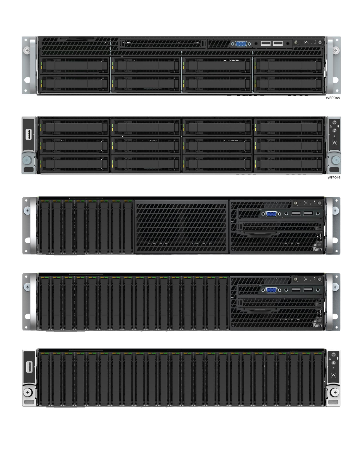
2.6 Front Drive Bay Options
Figure 11. 3.5" x 8 front drive bay configuration – R2308WFxxxx
Figure 12. 3.5" x 12 front drive bay configuration – R2312WFxxxx
Figure 13. 2.5" x 8 front drive bay configuration – R2208WFxxxx
Figure 14. 2.5" x 16 front drive bay configuration – R2208WFxxxx + 8 Drive Accessory Kit
Figure 15. 2.5" x 24 front drive bay configuration – R2224WFxxxx
28
Page 29
Intel® Server System R2000WF Product Family Technical Product Specification
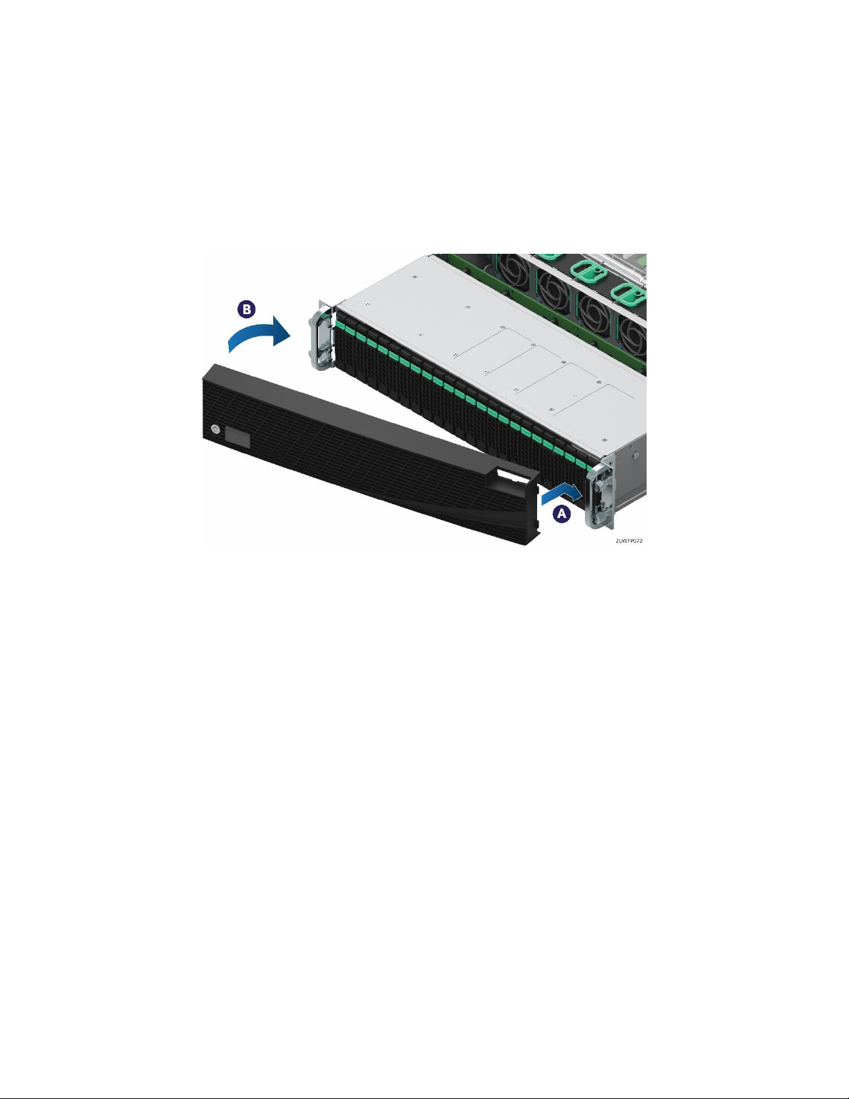
2.7 Locking Front Bezel Support
The Intel 2U chassis includes features designed into the rack handles and front drive bay by to support a
locking front bezel.
Note: Intel will not offer a front bezel accessory option. OEMs looking to develop a locking front bezel can
obtain necessary CAD files of the chassis from Intel to aid with front bezel development. Contact your local
Intel representative for additional information.
Figure 16. Concept Reference Design – Front Bezel Installation
29
Page 30
Intel® Server System R2000WF Product Family Technical Product Specification
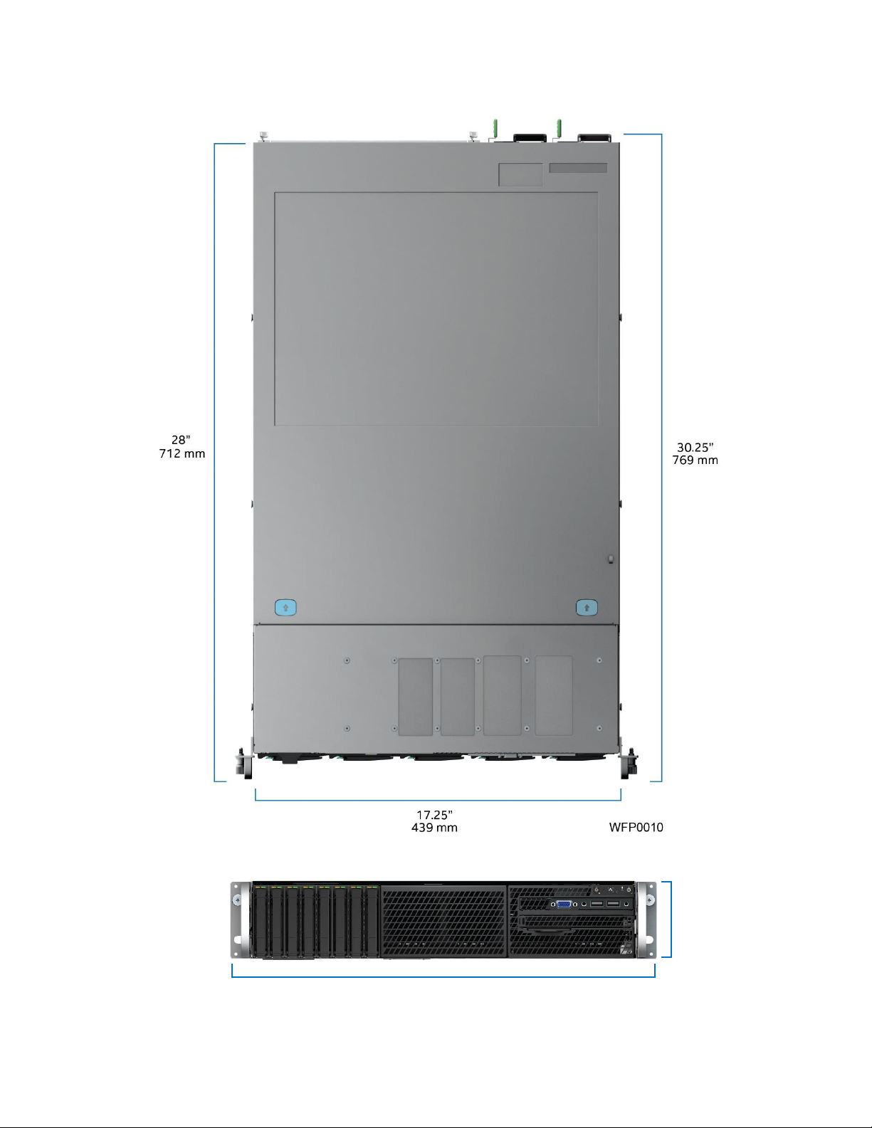
3.5”
89 mm
19”
482.6 mm
2.8 System Dimensional Data
2.8.1 Chassis Dimensions, 2.5” Drive Bay
Figure 17. Chassis dimensions, 2.5” drive bay
30
Page 31

Intel® Server System R2000WF Product Family Technical Product Specification
2.8.2 Label Emboss Dimensions
Figure 18. Label emboss dimensions
31
Page 32

Intel® Server System R2000WF Product Family Technical Product Specification
45 x 19 mm
46mm x 26 mm
2.8.3 Pull-Out Tab Label Emboss Dimensions
Figure 19. Pull-out tab label emboss dimensions, non-storage models
Figure 20. Pull-out tab label area dimensions, storage models
32
Page 33
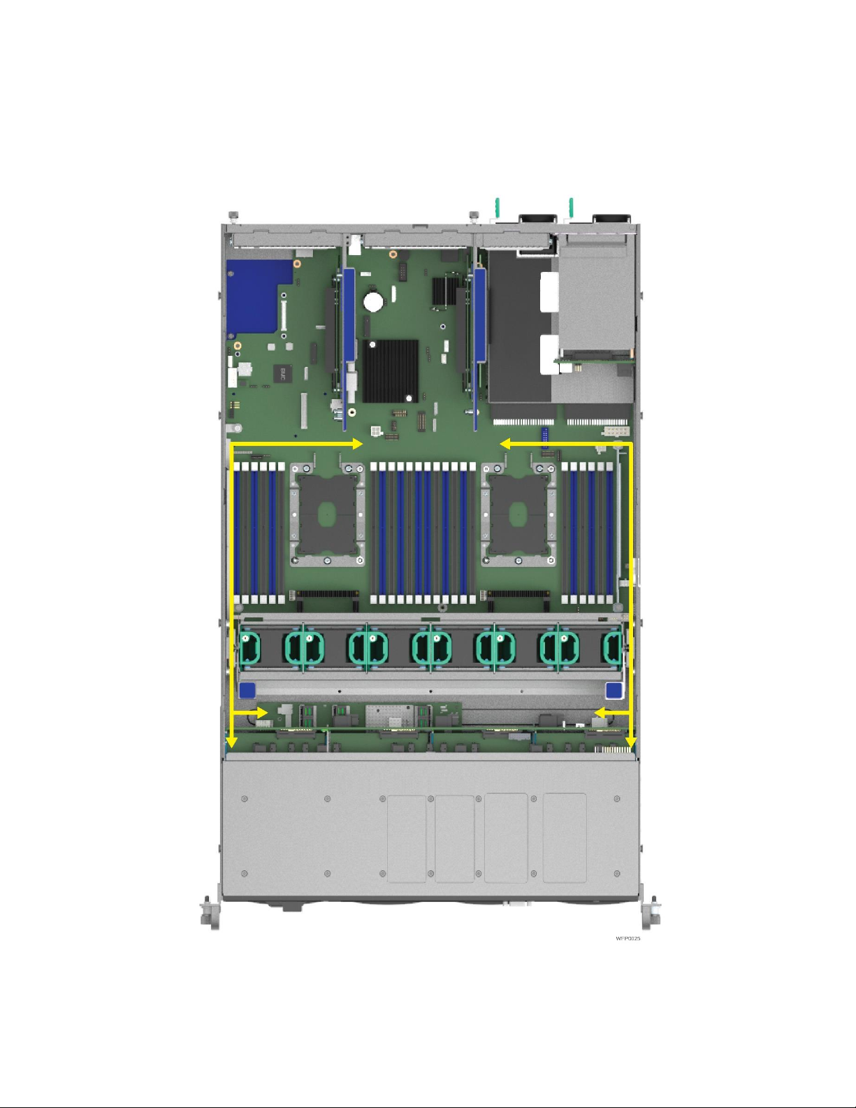
Intel® Server System R2000WF Product Family Technical Product Specification
2.9 System Cable Routing Channels
The 2U system provides cable routing channels along each chassis sidewall. No cables should be routed
directly in front of the system fans or through the center of the server board between the memory slots and
CPU sockets. The system fan assembly must be removed before routing cables.
See Appendix E, System Cable Routing Diagrams for additional information on supported cable routing.
Figure 21. System cable routing channels
33
Page 34

Intel® Server System R2000WF Product Family Technical Product Specification
2.10 Available Rack and Cabinet Mounting Kit Options
Advisory Note: Available rack and cabinet mounting kits are not designed to support shipment of the server
system while installed in a rack. If you chose to do so, Intel advises you verify your shipping configuration
with appropriate shock and vibration testing, before shipment. Intel does not perform shipping tests which
cover the complex combination of unique rack offerings and custom packaging options.
Caution: Exceeding the specified maximum weight limit of a given rail kit or misalignment of the server in the
rack may result in failure of the rack rails, causing damage to the system or personal injury. Using two people
or the use of a mechanical assist tool to install and align the server into the rack is highly recommended.
AXXELVRAIL – Enhanced Value Rack Mount Rail Kit
o 1U, 2U, 4U compatible
o Tool-less chassis attach
o Tools required to attach to rails to rack
o Rack installation length adjustment from 610mm ~ 765mm
o 424mm travel distance (2/3 extension from rack)
o 130 lbs. (59 kg) max support weight
AXXFULLRAIL – Premium Rail Kit with Cable Management Arm (CMA) support
o 2U compatible
o Tool-less chassis attach
o Full extension from rack
o 800mm travel distance
o 99 lbs. (45 Kgs) max supported weight
AXXSHRTRAIL - Premium quality rails with no CMA support
o 2U Compatible
o Tool-less installation
o Full extension from rack
o 788mm travel distance
o 99 lbs. (45 Kgs) max supported weight
AXX2POSTBRCKT – 2-Post Fixed Mount Bracket Kit
o 1U and 2U compatible
o Tools required to attach components to rack
AXXCMA2 – Cable Management Arm (supports AXXFULLRAIL only)
34
Page 35

Intel® Server System R2000WF Product Family Technical Product Specification
Parameter
Limits
Temperature
Operating
ASHRAE Class A2 – Continuous Operation. 10 °C to 35 ° C (50 °F to 95 °F) with the
maximum rate of change not to exceed 10 °C per hour.
ASHRAE Class A3 – Includes operation up to 40 °C for up to 900 hrs per year.
ASHRAE Class A4 – Includes operation up to 45 °C for up to 90 hrs per year.
Shipping
-40 °C to 70 °C (-40 °F to 158 °F)
Altitude
Operating
Support operation up to 3050 m with ASHRAE class de-ratings.
Humidity
Shipping
50% to 90%, non-condensing with a maximum wet bulb of 28 °C (at temperatures from
25 °C to 35 °C)
Shock
Operating
Half sine, 2 g, 11 msec
Unpackaged
Trapezoidal, 25 g, velocity change is based on packaged weight
Packaged
ISTA (International Safe Transit Association) Test Procedure 3A 2008
Vibration
Unpackaged
5 Hz to 500 Hz, 2.20 g RMS random
Packaged
ISTA (International Safe Transit Association) Test Procedure 3A 2008
AC-DC
Voltage
90 Hz to 132 V and 180 V to 264 V
Frequency
47 Hz to 63 Hz
Source Interrupt
No loss of data for power line drop-out of 12 msec
Surge Nonoperating and
operating
Unidirectional
Line to earth Only
AC Leads 2.0 kV
I/O Leads 1.0 kV
DC Leads 0.5 kV
ESD
Air Discharged
12.0 kV
Contact Discharge
8.0 kV
Acoustics
Sound Power
Measured
Power
<300 W ≥300 W ≥600 W ≥1000 W
Servers/Rack
Mount Sound
Power Level
7.0 7.0 7.0 7.0
Note: System configurations that include one or more Intel® Xeon Phi™ co-processor
cards may exhibit sound power levels of up to 8.0 BA.
2.11 System Level Environmental Limits
The following table defines the system level operating and non-operating environmental limits.
Table 4. System environmental limits summary
For system configuration requirements and limitations, refer to Appendix D in this document or the Intel®
S2600WF Product Family Power Budget and Thermal Configuration Tool.
35
Page 36

Intel® Server System R2000WF Product Family Technical Product Specification
iPC
Product Type
Packaged Gross
Weight (kg)
Packaged Gross
Weight (lbs)
Un-packaged Net
Weight (kg)
Un-packaged Net
Weight (lbs)
R2000WFXXX
Chassis
13.08
28.78
6.52
14.34
R2312WFXXX
Chassis
13.06
28.73
6.495
14.29
R2308WFxxx
L6 System
22.88
50.34
16.32
35.9
R2312WFxxx
L6 System
23.41
51.5
16.845
37.06
R2208WFxxx
L6 System
22.35
49.17
15.785
34.73
R2224WFxxx
L6 System
24.13
53.09
17.565
38.64
2.12 System Packaging
The original Intel packaging is designed to provide protection to a fully configured system and tested to
meet International Safe Transit Association (ISTA) Test Procedure 3A (2008). The packaging is also designed
to be re-used for shipment after system integration has been completed.
The original packaging includes two layers of boxes – an inner box and the outer shipping box – and various
protective inner packaging components. The boxes and packaging components are designed to function
together as a protective packaging system. When reused, all of the original packaging material must be used,
including both boxes and each inner packaging component. In addition, all inner packaging components
must be reinstalled in the proper location to ensure adequate protection of the system for subsequent
shipment.
Note: The design of the inner packaging components does not prevent improper placement within the
packaging assembly. There is only one correct packaging assembly that allows the package to meet the ISTA
Test Procedure 3A (2008) limits. See the Intel® Server System R2000WF Product Family System Integration
and Service Guide for complete packaging assembly instructions.
Failure to follow the specified packaging assembly instructions may result in damage to the system during
shipment.
Outer shipping box external dimensions
o Length: 983 mm
o Breadth: 577 mm
o Height: 260 mm
Inner box internal dimension
o Length: 956 mm
o Breadth: 550 mm
o Height: 202 mm
Table 5. Product weight information
Note: An L6 system does not include processors, memory, drives, or add-in cards. It is the system
configuration shipped from Intel. Weights of integrated system (system configurations that include the items
above) vary depending on the final system configuration. For the 2U product family, a fully integrated unpackaged system can weigh upwards of 65 lbs (29.5 kg).
36
Page 37

Intel® Server System R2000WF Product Family Technical Product Specification
3. System Power
This chapter provides a high level overview of the features and functions related to system power.
3.1 Power Supply Configurations
The server system can have up to two power supply modules installed and can support the following power
supply configurations: 1+0 (single power supply), 1+1 redundant power, and 2+0 combined power (nonredundant). 1+1 redundant power and 2+0 combined power configurations are automatically configured
depending on the total power draw of the system. If the total system power draw exceeds the power capacity
of a single power supply module, then power from the second power supply module is utilized. Should this
occur, power redundancy is lost. In a 2+0 power configuration, total power available maybe less than twice
the rated power of the installed power supply modules due to the amount of heat produced with both
supplies providing peak power. Should system thermal levels exceed programmed limits, platform
management attempts to keep the system operational. For details, see section 3.6 and chapter 4.
Caution: Installing two power supply units with different wattage ratings in a system is not supported. Doing
so does not provide power supply redundancy and results in multiple errors being logged by the system.
The power supplies are modular, allowing for tool-less insertion and extraction from a bay in the back of the
chassis. When inserted, the card edge connector of the power supply mates blindly to a matching slot
connector on the server board.
Figure 22. Power supply module identification
In the event of a power supply failure, redundant 1+1 power supply configurations have support for hotswap extraction and insertion. The AC input is auto-ranging and power factor corrected.
37
Page 38

Intel® Server System R2000WF Product Family Technical Product Specification
Loading
100% of maximum
50% of maximum
20% of maximum
10% of maximum
Minimum Efficiency
91%
94%
90%
82%
Loading
100% of maximum
50% of maximum
20% of maximum
10% of maximum
Minimum Efficiency
91%
96%
94%
90%
Loading
100% of maximum
50% of maximum
20% of maximum
10% of maximum
Minimum Efficiency
88%
92%
88%
80%
3.2 Power Supply Module Options
There are three power supply options available for this server product family:
- 1100W AC 80 Plus Platinum – iPC AXX1100CRPS
- 1300W AC 80 Plus Titanium – iPC AXX1300TCRPS
- 750W DC 80 Plus Gold – iPC AXX750DCCRPS
iPC= Intel product code
3.2.1 Power Supply Module Efficiency
The following tables provide the required minimum efficiency level at various loading conditions. These are
provided at three different load levels: 100%, 50% and 20%.
The AC power supply efficiency is tested over an AC input voltage range of 115 VAC to 220 VAC.
Table 6. 1100 Watt AC power supply efficiency (80 Plus Platinum)
Table 7. 1300 Watt AC power supply efficiency (80 Plus Titanium)
The DC power supply efficiency is tested with a 53 V DC input.
Table 8. 750 Watt DC power supply efficiency (80 Plus Gold)
38
Page 39

Intel® Server System R2000WF Product Family Technical Product Specification
1300W AC Power Supply Module
750W DC Power Supply Module
AC Power Cable Connectors
DC Power Cable Connectors
3.2.2 Power Supply Module Mechanical Overview
1100W AC Power Supply
Figure 23. Power supply module mechanical overview
The physical size of the 1100 W AC power supply enclosure is 39 mm x 74 mm x 185 mm. The power supply
includes dual in-line 40 mm fans, with one mounted inside the enclosure, and the other extending outside
the enclosure.
Note: The second fan protrudes from the back of the power supply bay, making the total length 213 mm
front to back.
The power supply has a card edge output that interfaces with a 2x25 card edge connector in the system.
39
Page 40

Intel® Server System R2000WF Product Family Technical Product Specification
74 mm
FCI 2x25 card
edge connector
10035388-102
A25
A1
B25
B1
2 mm
Retention latch
Airflow direction
8.5 mm
39 mm
Dual 40x40x28 mm fans
11 mm
185 mm
213 mm
74 mm
FCI 2x25 card
edge connector
A25
A1
B25
B1
2 mm
Retention latch
Airflow direction
8.5 mm
39 mm
40x40x28 mm fan
11 mm
185 mm
Figure 24. 1100W AC power supply module mechanical drawing
40
Figure 25. 1300W AC power supply module mechanical drawing
Page 41

Intel® Server System R2000WF Product Family Technical Product Specification
Cable Type
SJT
Wire Size
16 AWG
Temperature Rating
105ºC
Amperage Rating
13 A
Voltage Rating
125 V
Pin
Definition
1
+ Return
2
Safety Ground
3
- 48V
3.2.3 Power Cord Specification Requirements
The AC power cord used must meet the specification requirements listed in the following table.
Table 9. AC power cord specifications
Figure 26. AC power cord specification
Figure 27. DC power cord specification
Table 10. DC power cable connector pin-out
3.3 AC Power Supply Input Specifications
The following sections provide the AC input specifications for systems configured with AC power supply
modules.
The power supply meets the power factor requirements stated in the ENERGY STAR* Program Requirements
for Computer Servers; these requirements are stated below.
41
Page 42
Intel® Server System R2000WF Product Family Technical Product Specification
Output Power
10% load
20% load
50% load
100% load
Power Factor
> 0.65
> 0.80
> 0.90
> 0.95
Output power
10% load
20% load
50% load
100% load
Power factor
> 0.90
> 0.96
> 0.98
> 0.99
Current THD
< 20%
< 10%
< 8%
< 5%
Parameter
MIN
Rated
VMAX
Startup VAC
Power Off VAC
Voltage (110)
90 Vrms
100-127 Vrms
140 Vrms
85 VAC +/-4 VAC
74 VAC +/-5 VAC
Voltage (220)
180 Vrms
200-240 Vrms
264 Vrms
Frequency
47 Hz
50/60
63 Hz
Parameter
MIN
Rated
VMAX
Startup VAC
Power Off VAC
Voltage (110)
90 Vrms
100-127 Vrms
140 Vrms
85VAC +/-4VAC
74VAC +/-5VAC
Voltage (220)
180 Vrms
200-240 Vrms
264 Vrms
Frequency
47 Hz
50/60
63 Hz
3.3.1 Power Factor
Table 11. AC Power Factor – 1100W Power Supply
Tested at 230 VAC, 50 Hz and 60 Hz and 115 VAC, 60 Hz.
Table 12 . AC Power Factor - 1300W Power Supply
Tested at 230Vac, 50Hz
3.3.2 AC Input Voltage Specification
The power supply operates within all specified limits over the following input voltage range. Harmonic
distortion of up to 10% of the rated line voltage does not cause the power supply to go out of specified
limits. Application of an input voltage below 85 VAC does not cause damage to the power supply, including a
blown fuse.
Table 13. AC input voltage range, 1100 W power supply
Table 14. AC input voltage range, 1300 W power supply
Maximum input current at low input voltage range is measured at 90 VAC, at max load.
Maximum input current at high input voltage range is measured at 180 VAC, at max load.
This requirement is not to be used for determining agency input current markings.
3.3.3 AC Line Isolation Requirements
The power supply meets all safety agency requirements for dielectric strength. Transformer isolation
between primary and secondary windings must comply with the 3000 VAC (4242 VDC) dielectric strength
criteria. If the working voltage between primary and secondary dictates a higher dielectric strength test
voltage the highest test voltage should be used. In addition, the insulation system must comply with
reinforced insulation per safety standard IEC 950. Separation between the primary and secondary circuits,
and primary to ground circuits, must comply with the IEC 950 spacing requirements.
3.3.4 AC Line Dropout/Holdup
An AC line dropout is defined to be when the AC input drops to 0VAC at any phase of the AC line for any
length of time. During an AC dropout the power supply meets dynamic voltage regulation requirements. An
42
Page 43

Intel® Server System R2000WF Product Family Technical Product Specification
Loading
Holdup time
70%
10msec
Loading during AC dropout / holdup
Holdup time / Dropout duration
0% to 70% of rated load
10msec
Duration
Sag
Operating AC Voltage
Line Frequency
Performance Criteria
0 to 1/2 AC cycle
95%
Nominal AC Voltage ranges
50/60Hz
No loss of function or performance
> 1 AC cycle
>30%
Nominal AC Voltage ranges
50/60Hz
Loss of function acceptable, self-recoverable
AC line dropout of any duration does not cause tripping of control signals or protection circuits. If the AC
dropout lasts longer than the holdup time, the power supply recovers and meets all turn on requirements.
The power supply meets the AC dropout requirement over rated AC voltages and frequencies. A dropout of
the AC line for any duration does not cause damage to the power supply.
Table 15. AC line holdup time, 1100 W power supply
Table 16. AC line holdup time, 1300 W power supply
3.3.4.1 AC Line 12 VSB Holdup
The 12 VSB output voltage stays in regulation under its full load (static or dynamic) during an AC dropout of
70 msec minimum (12 VSB holdup time) whether the power supply is in an ON or OFF state (PSON asserted
or de-asserted).
3.3.5 AC Line Fuse
The power supply has one line fused in the single line fuse on the line (hot) wire of the AC input. The line
fusing is acceptable for all safety agency requirements. The input fuse shall be a slow blow type. AC inrush
current does not cause the AC line fuse to blow under any conditions. All protection circuits in the power
supply do not cause the AC fuse to blow unless a component in the power supply has failed. This includes
DC output load short conditions.
3.3.6 AC Inrush
AC line inrush current does not exceed (55 A peak – 1100 W PSU, 35 A peak – 1300 W PSU), for up to one-
quarter of the AC cycle, after which the input current is no more than the specified maximum input current.
The peak inrush current is less than the ratings of its critical components (including input fuse, bulk rectifiers,
and surge limiting device).
The power supply meets the inrush requirements for any rated AC voltage during turn on at any phase of AC
voltage, during a single cycle AC dropout condition, upon recovery after AC dropout of any duration, and
over the specified temperature range (Top).
3.3.7 AC Line Transient Specification
AC line transient conditions are defined as “sag” and “surge” conditions. “Sag” conditions, also commonly
referred to as “brownout,” are defined as the AC line voltage dropping below nominal voltage conditions.
“Surge” is defined as conditions when the AC line voltage rises above nominal voltage.
The power supply meets the requirements under the following AC line sag and surge conditions.
Table 17. AC line sag transient performance (10 sec interval between each sagging)
43
Page 44

Intel® Server System R2000WF Product Family Technical Product Specification
Duration
Surge
Operating AC Voltage
Line Frequency
Performance Criteria
Continuous
10%
Nominal AC Voltages
50/60 Hz
No loss of function or performance
0 to ½ AC cycle
30%
Mid-point of nominal AC Voltages
50/60 Hz
No loss of function or performance
Parameter
VAC
Min
Max.
Continuous
20sec
Peak 2
10msec
Peak
3,4
100µsec
Peak
Unit
12V main
200-
240VAC
0.0
108
120
130
150 5
A
12V main
100-
127VAC
0.0
62
70
80
NA
A
12Vstby 1
0.0
2.1
2.4
NA
NA
A
Level
Description
A
The apparatus continues to operate as intended. No degradation of performance.
B
The apparatus shall continue to operate as intended. No degradation of performance beyond spec limits.
C
Temporary loss of function is allowed provided the function is self-recoverable or can be restored by the operation of the
controls.
Table 18. AC line surge transient performance
3.3.8 DC Output Specification
The following tables defines the minimum power and current ratings. The power supply 1300W must meet
both static and dynamic voltage regulation requirements for all conditions.
Table 19. Maximum Load Ratings
3.3.9 Susceptibility Requirements
The power supply meets the following electrical immunity requirements when connected to a cage with an
external EMI filter which meets the criteria defined in the SSI document EPS Power Supply Specification. For
further information on Intel standards, please request a copy of the Intel Environmental Standards
Handbook.
Table 20. Performance criteria
3.3.10 Electrostatic Discharge Susceptibility
The power supply complies with the limits defined in EN 55024: 1998/A1: 2001/A2: 2003 using the IEC
61000-4-2: Edition 1.2: 2001-04 test standard and performance criteria B defined in Annex B of CISPR 24.
3.3.11 Fast Transient/Burst
The power supply complies with the limits defined in EN55024: 1998/A1: 2001/A2: 2003 using the IEC
61000-4-4: Second edition: 2004-07 test standard and performance criteria B defined in Annex B of CISPR
24.
3.3.12 Radiated Immunity
The power supply complies with the limits defined in EN55024: 1998/A1: 2001/A2: 2003 using the IEC
61000-4-3: Edition 2.1: 2002-09 test standard and performance criteria A defined in Annex B of CISPR 24.
3.3.13 Surge Immunity
The power supply is tested with the system for immunity to the following for each power supply option:
44
Page 45

Intel® Server System R2000WF Product Family Technical Product Specification
Output
VOLTAGE
Input voltage
range
OVER CURRENT LIMITS
OCP DELAY
+12V
180 – 264VAC
132A min / 138A max
50msec min / 200msec max
152A min / 160A max
5msec min / 20msec max
+12V
90 – 140VAC
72A min / 77A max
50msec min / 200msec max
90 – 140VAC
103A min; 107A max
5msec min / 20msec
12VSB
90 – 264VAC
2.5A min; 3.5A max
5msec min / 20msec
Output Voltage
Input Voltage Range
Over Current Limits
+12 V
90 – 264 VAC
120 A min/132 A max
Trip delay
50 msec min
12 VSB
90 – 264 VAC
2.5 A min/3.5 A max
1100W Power Supply – AC unidirectional wave; 2.6 kV line to ground and 1.3 kV line to line, per EN
55024: 1998/A1: 2001/A2: 2003, EN 61000-4-5: Edition 1.1:2001-04.
1300W Power Supply – AC Unidirectional wave; 2kV line to ground and 1kV line to line, per EN
55024: 1998/A1: 2001/A2: 2003, EN 61000-4-5: Edition 1.1:2001-04 .
The pass criteria include the following: No unsafe operation is allowed under any condition; all power supply
output voltage levels to stay within proper specification levels; No change in operating state or loss of data
during and after the test profile; No component damage under any condition.
The power supply complies with the limits defined in EN55024: 1998/A1: 2001/A2: 2003 using the IEC
61000-4-5: Edition 1.1:2001-04 test standard and performance criteria B defined in Annex B of CISPR 24.
3.3.14 Power Recovery
The power supply recovers automatically after an AC power failure. AC power failure is defined to be any loss
of AC power that exceeds the dropout criteria.
3.3.15 Voltage Interruptions
The power supply complies with the limits defined in EN55024: 1998/A1: 2001/A2: 2003 using the IEC
61000-4-11: Second Edition: 2004-03 test standard and performance criteria C defined in Annex B of CISPR
24.
3.3.16 Protection Circuits
Protection circuits inside the power supply cause only the power supply’s main outputs to shut down. If the
power supply latches off due to a protection circuit tripping, an AC cycle OFF for 15 seconds and a PSON#
cycle HIGH for one second reset the power supply.
3.3.16.1 Over-Current Protection
The power supply has current limit to prevent the outputs from exceeding the values shown in Table 21. If
the current limits are exceeded, the power supply shuts down and latches off. The latch is cleared by
toggling the PSON# signal or by an AC power interruption. The power supply is not damaged from repeated
power cycling in this condition. 12 VSB is auto-recovered after removing the over current protection limit.
Table 21. Over current protection, 1300 W power supply
3.3.16.2 Over Voltage Protection (OVP)
The power supply over voltage protection is locally sensed. The power supply shuts down and latches off
after an over voltage condition occurs. This latch is cleared by an AC power interruption. The values are
measured at the output of the power supply’s connectors. The voltage never exceeds the maximum levels
45
Table 22. Over current protection, 1100 W power supply
Page 46

Intel® Server System R2000WF Product Family Technical Product Specification
Output Voltage
Minimum (V)
Maximum (V)
+12 V
13.5
14.5
+12 VSB
13.5
14.5
Output Voltage
Minimum (V)
Maximum (V)
+12V
13.5
14.5
+12VSB
13.5
14.5
Power Supply Condition
LED State
Output ON and OK
Solid green
No AC power to all power supplies
Off
AC present/Only 12 VSB on (PS off) or PS in cold redundant state
1 Hz blinking green
AC cord unplugged or AC power lost; with a second power supply in parallel still with AC input power
Solid amber
Power supply warning events where the power supply continues to operate; high temp, high power,
high current, slow fan
1 Hz blinking amber
Power supply critical event causing a shutdown; failure, OCP, OVP, fan fail
Solid amber
Power supply FW updating
2 Hz blinking green
when measured at the power connectors of the power supply connector during any single point of fail. The
voltage never trips any lower than the minimum levels when measured at the power connector. 12 VSB is
auto-recovered after removing OVP limit.
Table 23. Over voltage protection (OVP) limits, 1300 W power supply
Table 24. Over voltage protection (OVP) limits, 1100 W power supply
3.3.16.3 Over Temperature Protection (OTP)
The power supply is protected against over temperature conditions caused by loss of fan cooling or
excessive ambient temperature. In an OTP condition, the PSU shuts down. OT warning SMBAlert# assertion
always precedes the OTP shutdown. When the power supply temperature drops to within specified limits,
the power supply restores power automatically, while the 12 VSB remains always on. The OTP circuit has
built-in margin such that the power supply does not oscillate on and off due to temperature recovering
condition. The OTP trip temperature level is at least 5 C higher than SMBAlert over temperature warning
threshold level.
3.3.17 Power Supply Status LED
There is a single bi-color LED to indicate power supply status. The LED operation is defined in Table 25.
Table 25. LED indicators
3.4 DC Power Supply Input Specifications (iPC – AXX750DCCRPS)
The following sections provide the DC input specifications for systems configured with DC power supply
modules.
Note: Product safety regulations pertaining to the use of DC power supplies require that chassis grounding
studs be used for all DC power supply configurations. In the event that chassis grounding studs are not
available on a given server chassis, systems must be configured with two DC power supplies, each connected
to separate ground wires while the system is operational.
3.4.1 DC Input Voltage
The power supply must operate within all specified limits over the following input voltage range.
46
Page 47

Intel® Server System R2000WF Product Family Technical Product Specification
Parameter
Minimum
Rated
Maximum
DC Voltage
-40.5 VDC
-48 VDC/-60 VDC
-75 VDC
Input Current
24bA
12.5 A
Loading
Holdup Time
750 W (100%)
0.2 msec
Duration
Slope/Rate
Output
Performance Criteria
200 µsec max
-48 V → -30 V w/ +2 V/µs
Rated DC voltages
No loss of function or performance
-30 V → -48 V w/ -2 V/µs
Rated DC voltages
No loss of function or performance
Table 26. DC input rating
3.4.2 DC Input Fuse
The power supply should have the -48 VDC input fused. The fusing shall be acceptable for all safety agency
requirements. DC inrush current shall not cause the fuse to blow under any conditions. No protection circuits
in the power supply shall cause the DC fuse to blow unless a component in the power supply has failed. This
includes DC output load short conditions.
3.4.3 DC Inrush Current
Maximum inrush current from power-on shall be limited to a level below the surge rating of the input line
cable; input diodes, fuse, and EMI filter components. To allow multiple power cycling events and DC line
transient conditions max I²t value shall not exceed 20% of the fuse max rating. Repetitive ON/OFF cycling of
the DC input line voltage should not damage the power supply or cause the input fuse to blow.
3.4.4 DC Input under Voltage
The power supply shall contain protection circuitry (under-voltage lock-out) such that the application of an
input voltage below the specified minimum specified, shall not cause damage (overstress) to the power
supply unit (due to over-heating or otherwise).
3.4.5 DC Holdup Time and Dropout
Table 27. DC holdup time
During a DC dropout of 0.2 msec or less the power supply must meet dynamic voltage regulation
requirements for every rated load condition. A DC line dropout of 0.2 msec or less shall not cause tripping of
control signals or protection circuits. Repeated every ten seconds starting at the minimum input voltage, DC
line dropout shall not damage the power supply under any specified load conditions. The PWOK signal shall
not go to a low state under these conditions. DC dropout transients in excess of 0.2 msec may cause
shutdown of the power supply or out of regulation conditions, but shall not damage the power supply. The
power supply should recover and meet all turn on requirements for DC dropouts that last longer than
0.2 msec. The power supply must meet the DC dropout requirement over rated DC voltages and output
loading conditions.
3.4.6 DC Line Surge Voltages (Line Transients)
The power supply should demonstrate tolerance for transients in the input DC power line caused by
switching or lightning. The power supply shall be primarily tested and must be compliant with the
requirements of EN61000-4-5: “Electrical Fast transients / Burst Requirements and Surge Immunity
Requirements” for surge withstand capability. The test voltage surge levels are to be 500Vpk for each Line to
Primary Earth Ground test (none required between the L1 and L2). The exact description can be found in
Intel Environmental Standards Handbook 2001.
47
Table 28. Line voltage transient limits
Page 48

Intel® Server System R2000WF Product Family Technical Product Specification
Level
Description
A
The apparatus shall continue to operate as intended. No degradation of performance.
B
The apparatus shall continue to operate as intended. No degradation of performance beyond spec limits.
C
Temporary loss of function is allowed provided the function is self-recoverable or can be restored by the
operation of the controls.
3.4.7 Susceptibility Requirements
The power supply shall meet the following electrical immunity requirements when connected to a cage with
an external EMI filter which meets the criteria defined in the SSI document EPS Power Supply Specification.
For further information on Intel standards, please request a copy of the Intel Environmental Standards
Handbook.
Table 29. Performance criteria
3.4.7.1 Electrostatic Discharge Susceptibility
The power supply shall comply with the limits defined in EN 55024: 1998 using the IEC 61000-4-2:1995 test
standard and performance criteria B defined in Annex B of CISPR 24. Limits shall comply with those specified
in the Intel Environmental Standards Handbook.
3.4.7.2 Fast Transient/Burst
The power supply shall comply with the limits defined in EN55024: 1998 using the IEC 61000-4-4:1995 test
standard and performance criteria B defined in Annex B of CISPR 24. Limits shall comply with those specified
in the Intel Environmental Standards Handbook.
3.4.7.3 Radiated Immunity
The power supply shall comply with the limits defined in EN55024: 1998 using the IEC 61000-4-3:1995 test
standard and performance criteria A defined in Annex B of CISPR 24. Limits shall comply with those specified
in the Intel Environmental Standards Handbook. Additionally, the power supply must comply with field
strength requirements specified in GR 1089 (10 V/m).
3.4.7.4 Surge Immunity
The power supply shall be tested with the system for surge immunity, per EN 55024:1998, EN 61000-45:1995 and ANSI C62.45: 1992.
The pass criteria include the following: No unsafe operation is allowed under any condition; all power supply
output voltage levels to stay within proper spec levels; No change in operating state or loss of data during
and after the test profile; No component damage under any condition.
The power supply shall comply with the limits defined in EN55024: 1998 using the IEC 61000-4-5:1995 test
standard and performance criteria B defined in Annex B of CISPR 24. Limits shall comply with those specified
in the Intel Environmental Standards Handbook.
3.4.8 Protection Circuits
Protection circuits inside the power supply shall cause only the power supply’s main outputs to shut down.
If the power supply latches off due to a protection circuit tripping, a DC cycle OFF for 15 sec and a PSON#
cycle HIGH for 1 sec shall be able to reset the power supply.
3.4.8.1 Over Current Protections (OCP)
The power supply shall have current limit to prevent the outputs from exceeding the values shown in Table
30. If the current limits are exceeded, the power supply shall shutdown and latch off. The latch will be
cleared by toggling the PSON# signal or by a DC power interruption. The power supply shall not be damaged
from repeated power cycling in this condition. 12VSB will be auto-recovered after removing OCP limit.
Table 30. Over current protection
48
Page 49

Intel® Server System R2000WF Product Family Technical Product Specification
Output Voltage
Input Voltage Range
Over Current Limits
+12V
72 A min/78 A max
12VSB
2.5 A min/3.5 A max
Output Voltage
Minimum (V)
Maximum (V)
+12 V
13.3
14.5
+12 VSB
13.3
14.5
3.4.8.2 Over Voltage Protection (OVP)
The power supply over voltage protection shall be locally sensed. The power supply shall shutdown and
latch off after an over voltage condition occurs. This latch shall be cleared by toggling the PSON# signal or
by a DC power interruption. The values are measured at the output of the power supply’s connectors. The
voltage shall never exceed the maximum levels when measured at the power supply connector during any
single point of fail. The voltage shall never trip any lower than the minimum levels when measured at the
power connector. 12 VSB will be auto-recovered after removing OVP limit.
Table 31. Over voltage protection limits
3.4.8.3 Over Temperature Protection (OTP)
The power supply will be protected against over temperature conditions caused by loss of fan cooling or
excessive ambient temperature. In an OTP condition the PSU will shut down. When the power supply
temperature drops to within specified limits, the power supply shall restore power automatically, while the
12 VSB remains always on. The OTP circuit must have built in margin such that the power supply will not
oscillate on and off during a temperature recovering condition. The OTP trip level shall have a minimum of
4 °C of ambient temperature margin.
3.5 Cold Redundancy Support
The power supplies support cold redundancy allowing them to go into a low-power state (that is, a cold
redundant state) in order to provide increased power usage efficiency when system loads are such that both
power supplies are not needed. When the power subsystem is in cold redundant mode, only the needed
power supply to support the best power delivery efficiency is ON. Any additional power supplies, including
the redundant power supply, is in cold standby state.
Each power supply has an additional signal that is dedicated to supporting cold redundancy: CR_BUS. This
signal is a common bus between all power supplies in the system. CR_BUS is asserted when there is a fault in
any power supply or the power supplies’ output voltages fall below the Vfault threshold. Asserting the
CR_BUS signal causes all power supplies in cold standby state to power ON.
Enabling power supplies to maintain optimum efficiency is achieved by looking at the load share bus voltage
and comparing it to a programmed voltage level via a PMBus command.
Whenever there is no active power supply on the cold redundancy bus driving a HIGH level on the bus, all
power supplies are ON no matter their defined cold redundant roll (active or cold standby). This guarantees
that incorrect programming of the cold redundancy states of the power supply will never cause the power
subsystem to shut down or become over loaded. The default state of the power subsystem is all power
supplies ON. There needs to be at least one power supply in cold redundant active state or standard
redundant state to allow the cold standby state power supplies to go into cold standby state.
3.5.1 Powering on Cold Standby Supplies to Maintain Best Efficiency
Power supplies in cold standby state shall monitor the shared voltage level of the load share signal to sense
when it needs to power on. Depending upon which position (1, 2, or 3) the system defines that power supply
to be in, the cold standby configuration slightly changes the load share threshold that the power supply shall
power on at.
49
Page 50

Intel® Server System R2000WF Product Family Technical Product Specification
State
Enable Threshold for
VCR_ON_EN
Disable Threshold for
VCR_ON_DIS
CR_BUS De-Asserted/
Asserted States
Standard Redundancy
NA; Ignore dc/dc_ active# signal; power supply is always ON
OK = High, Fault = Low
Cold Redundant Active
NA; Ignore dc/dc_ active# signal; power supply is always ON
OK = High, Fault = Low
Cold Standby 1 (02h)
3.2 V (40% of max)
3.2 V x 0.5 x 0.9 = 1.44 V
OK = Open, Fault = Low
Cold Standby 2 (03h)
5.0 V (62% of max)
5.0 V x 0.67 x 0.9 = 3.01 V
OK = Open, Fault = Low
Cold Standby 3 (04h)
6.7 V (84% of max)
6.7 V x 0.75 x 0.9 = 4.52 V
OK = Open, Fault = Low
Table 32. Example load share threshold for activating supplies
Note: Maximum load share voltage is 8.0 V at 100% of rated output power.
Note: Load share bus thresholds are examples. For a given power supply, these will be customized to
maintain the best efficiency curve for that specific model.
3.5.2 Powering on Cold Standby Supplies during a Fault or Over Current Condition
When an active power supply asserts its CR_BUS signal (pulling it low), all parallel power supplies in cold
standby mode will power on within 100 μsec.
3.5.3 BMC Requirements
The BMC uses the Cold_Redundancy_Config command to define and configure the power supply’s role
in cold redundancy and to turn on/off cold redundancy.
To allow for equal loading over the life time of installed power supplies, the BMC shall schedule a rolling re-
configuration of installed power supplies so that each alternates between being the “Active” power supply
and the “Cold Stby” power supply.
Events that trigger a re-configuration of the power supplies using the Cold_Redundancy_Config
command are listed below.
AC power ON
PSON power ON
Power supply failure
Power supply inserted into system
3.5.4 Power Supply Turn on Function
Powering on and off of the cold standby power supplies is only controlled by each PSU sensing the Vshare
bus. Once a power supply turns on after crossing the enable threshold, it lowers itself to the disable
threshold. The system defines the position of each power supply in the cold redundant operation. It does
this each time the system is powered on, a power supply fails, or a power supply is added to the system.
The system is relied upon to tell each power supply where it resides in the cold redundancy scheme.
3.6 Closed Loop System Throttling (CLST)
The server system has support for Closed Loop System Throttling (CLST) which prevents the system from
crashing if a power supply module is overloaded or over heats. Should system power reach a preprogrammed power limit, CLST throttles system memory and/or processors to reduce power. System
performance is impacted should this occur.
50
Page 51

Intel® Server System R2000WF Product Family Technical Product Specification
Pin
Name
Pin
Name
A1
GND
B1
GND
A2
GND
B2
GND
A3
GND
B3
GND
A4
GND
B4
GND
A5
GND
B5
GND
A6
GND
B6
GND
A7
GND
B7
GND
A8
GND
B8
GND
A9
GND
B9
GND
A10
+12V
B10
+12V
A11
+12V
B11
+12V
A12
+12V
B12
+12V
A13
+12V
B13
+12V
A14
+12V
B14
+12V
A15
+12V
B15
+12V
A16
+12V
B16
+12V
A17
+12V
B17
+12V
A18
+12V
B18
+12V
A19
PMBus SDA
B19
A0 (SMBus address)
A20
PMBus SCL
B20
A1 (SMBus address)
A21
PSON
B21
12 VSB
A22
SMBAlert#
B22
Cold redundancy bus
A23
Return sense
B23
12V load share bus
A24
+12V remote sense
B24
No connect
A25
PWOK
B25
Compatibility check pin
3.7 Smart Ride Through (SmaRT)
The server system has support for Smart Ride Through Throttling (SmaRT) which increases the reliability for
a system operating in a heavy power load condition and to remain operational during an AC line dropout
event. For power supply hold up time requirements for AC line dropout events, see section 3.3.4.
When AC voltage is too low, a fast AC loss detection circuit inside each installed power supply asserts an
SMBALERT# signal to initiate a throttle condition in the system. System throttling reduces the bandwidth to
both system memory and CPUs, which in turn reduces the power load during the AC line drop out event
3.8 Server Board Power Connectors
The server board provides several connectors to provide power to various system options. This section
provide the pin-out definition and a brief usage description for each.
3.8.1 Power Supply Module Card Edge Connector
Each power supply module has a single 2x25 card edge output connection that plugs directly into a
matching slot connector on the server board. The connector provides both power and communication
signals to the server board. The following table defines the connector pin-out.
Table 33. Power supply module output power connector pin-out
3.8.2 Optional 12 V Power Connectors for High Power Add-in Cards
The server board includes two white 2x2-pin power connectors that provide supplemental power to high
power PCIe x16 add-in cards (Intel® Xeon Phi™ or non-Intel GPGPU) that have power requirements that
51
Page 52
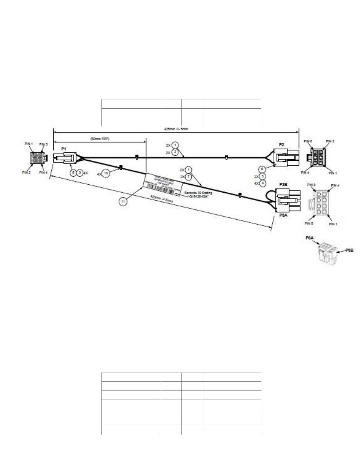
Intel® Server System R2000WF Product Family Technical Product Specification
Signal Description
Pin#
Pin#
Signal Description
P12V
3 1 GND
P12V
4 2 GND
Signal Description
Pin#
Pin#
Signal Description
GND
1 7 P12V_240VA3
GND
2 8 P12V_240VA3
GND
3 9 P12V_240VA2
GND
4
10
P12V_240VA2
GND
5
11
P12V_240VA1
GND
6
12
P12V_240VA1
exceed the 75 W maximum power supplied by the PCIe x16 riser slot. A cable from this connector may be
routed to a power connector on the given add-in card. Maximum power draw for each connector is 225 W,
but is also limited by available power provided by the power supply and the total power draw of the rest of
the system. A power budget for the complete system should be performed to determine how much
supplemental power is available to support any high power add-in cards configured in the system.
Each connector is labeled as “OPT_12V_PWR” on the server board. The following table provides the pin-out
for both connectors.
Table 34. Riser slot power pin-out (OPT_12V_PWR_#)
Figure 28. Power cable for the OPT_12V
The power cable for the OPT_12V_PWR connectors (shown in Figure 28) is included in the two-slot riser card
accessory kit (iPC – A2UL16RISER2 ) and can support both six- and eight-pin 12 V AUX power connectors
found on high power add-in cards.
3.8.3 Hot Swap Backplane Power Connector
The server board includes one white 2x6-pin power connector that is used to provide power for the hot
swap backplanes mounted in the front of the chassis only. On the server board, this connector is labeled as
“HSBP PWR”. The power for this connector is routed from two separate 12 V power rails, each capable of
supporting a current limit of 18 A. The following table provides the pin-out for this connector.
Table 35. Hot swap backplane power connector pin-out (“HSBP PWR")
52
Page 53

Intel® Server System R2000WF Product Family Technical Product Specification
Pin
Signal Name
Pin
Signal Name
1
P5V
4
P12V
2
P5V
5
P3V3
3
GND
6
GND
3.8.4 Peripheral Power Connector
The server board includes one brown 2x3-pin power connector intended to provide power to various
possible peripheral options including: Solid State Devices (SSDs) mounted to the top side of the air duct or
to the rear mounted two drive backplane accessory option. On the server board this connector is labeled as
“Peripheral PWR”. The following table provides the pin-out for this connector.
Table 36. Peripheral drive power connector pin-out (“Peripheral PWR”)
53
Page 54

Intel® Server System R2000WF Product Family Technical Product Specification
System Fan
PSU Fan
Total Airflow (CFM)
100%
auto
136.2
100%
100%
141.5
55%
auto
70.8
System Fan
PSU Fan
Total Airflow (CFM)
100%
auto
170.6
100%
100%
173.3
55%
auto
86.5
4. Thermal Management
The fully integrated system is designed to operate at external ambient temperatures of between 10 °C and
35 °C with limited excursion based operation up to 45 °C, as specified in Table 4. Working with integrated
platform management, several features within the system are designed to move air in a front to back
direction, through the system and over critical components to prevent them from overheating and allow the
system to operate with best performance.
Figure 29. System Airflow and Fan Identification
The following tables provide air flow data associated with the different system models within this 2U product
family and are provided for reference purposes only. The data was derived from actual wind tunnel test
methods and measurements using fully configured (worst case) system configurations. Lesser system
configurations may produce slightly different data results. In addition, the CFM data provided using server
management utilities that utilize platform sensor data may vary slightly from the data listed in the tables.
Note: For system BTU data, see the Intel® Server Board S2600WF Product Family Power Budget and Thermal
Configuration Tool.
Table 37. System volumetric airflow, Intel® Server System R2308WFxxx
Table 38 . System volumetric airflow, Intel® Server System R2308WFxxx w/Intel® Xeon Phi™ (passive)
54
Page 55

Intel® Server System R2000WF Product Family Technical Product Specification
System Fan
PSU Fan
Total Airflow (CFM)
100%
auto
77.9
100%
100%
80.0
55%
auto
40.3
System Fan
PSU Fan
Total Airflow (CFM)
100%
auto
154.6
100%
100%
159.1
55%
auto
84.0
System Airflow – R2208WFxxx w/Intel Xeon Phi (passive)
System Fan
PSU Fan
Total Airflow (CFM)
100%
auto
189.0
100%
100%
194.2
55%
auto
97.6
System Fan
PSU Fan
Total Airflow (CFM)
100%
auto
136.2
100%
100%
140.5
55%
auto
69.8
System Airflow – R2216WFxxx w/Intel Xeon Phi (passive)
System Fan
PSU Fan
Total Airflow (CFM)
100%
auto
163.4
100%
100%
165.7
55%
auto
87.0
System Fan
PSU Fan
Total Airflow (CFM)
100%
auto
105.5
100%
100%
108.4
55%
auto
48.9
Table 39. System volumetric airflow, Intel® Server System R2312WFxxx
Table 40. System volumetric airflow, Intel® Server System R2208WFxxx
Table 41 . System volumetric airflow, Intel® Server System R2208WFxxx w/Intel® Xeon Phi™ (passive)
Table 42. System volumetric airflow, Intel® Server System R2208WFxxx + 8 Drive Acc (16x2.5”)
Table 43 . System volumetric airflow, Intel® Server System R2208WFxxx + 8 Drive Acc (16x2.5”) w/Intel®
Xeon Phi™ (passive)
Table 44. System volumetric airflow, Intel® Server System R2224WFxxx
Note: Intel® Xeon Phi™ processor is not supported in Intel® Server Systems R2312WFxxx and R2224WFxxx.
Note: Airflow data is preliminary and is subject to change.
55
Page 56

Intel® Server System R2000WF Product Family Technical Product Specification
PCIe* Add-In Slot
Riser Slot #1
Riser Slot #2
Riser Slot #3
Top
100 LFM
200 LFM
100 LFM
Middle
100 LFM
200 LFM
100 LFM
Bottom
200 LFM
200 LFM
N/A
The Intel® Server System R2000WF product family supports short-term, excursion-based, operation up to
45 °C (ASHRAE A4) with limited performance impact. The configuration requirements and limitations are
described in the configuration matrix found in Appendix D of this document or in the Intel® S2600WF
Product Family Power Budget and Thermal Configuration Tool available as a download online at:
http://www.intel.com/support
The installation and functionality of several system components are used to maintain system thermals. They
include six managed 60 mm system fans, fans integrated into each installed power supply module, an air
duct, populated drive carriers, and installed CPU heats sinks. Drive carriers can be populated with a storage
device (SSD or HDD) or supplied drive blank. In addition, it may be necessary to have specific DIMM slots
populated with DIMMs or supplied DIMM blanks. System configurations that require population of specific
DIMM slots ship from Intel with DIMM blanks pre-installed. Pre-installed DIMM blanks should only be
removed when installing a memory module in its place. Chassis only products include DIMM blanks
separately in the accessory kit and must be installed in the appropriate DIMM slot locations as defined in the
following section.
4.1 Thermal Operation and Configuration Requirements
To keep the system operating within supported maximum thermal limits, the system must meet the
following operating and configuration guidelines:
The system is designed to sustain operations at an ambient temperature of up to 35 °C (ASHRAE
Class A2) with short term excursion based operation up to 45 °C (ASHRAE Class A4).
The system can operate up to 40 °C (ASHRAE Class A3) for up to 900 hours per year.
The system can operate up to 45 °C (ASHRAE Class A4) for up to 90 hours per year.
System performance may be impacted when operating within the extended operating temperature
range.
There is no long term system reliability impact when operating at the extended temperature range
within the documented limits.
Specific configuration requirements and limitations are documented in the configuration matrix found in
Appendix D of this document or in the Intel® Server Board S2600WF product family Power Budget and
Thermal Configuration Tool, available as a download online at http://www.intel.com/support.
The CPU-1 processor and CPU heat sink must be installed first. The CPU-2 heat sink must be installed at all
times, with or without a processor installed.
Thermally, a system supporting fan redundancy can support the following PCI add-in cards when the system
is operating at up to a maximum operating ambient temperature of 35 °C (ASHRAE Class 2).
Airflow for add-in cards is measured at local inlet. Add-in card thermal support limits are listed by riser and
by riser slot in the following tables. This limitation is driven primarily by fan failure performance.
Table 45. PCIe* add-in card airflow (LFM) support limits – R2312WFxxx and R2224WFxxx
56
Page 57

Intel® Server System R2000WF Product Family Technical Product Specification
PCIe* Add-In Slot
Riser Slot #1
Riser Slot #2
Riser Slot #3
Top
200 LFM
200 LFM
200 LFM
Middle
200 LFM
200 LFM
200 LFM
Bottom
300 LFM
300 LFM
N/A
Table 46. PCIe* add-in card airflow (LFM) support limits – R2208WFxxx, R2208WFxxx + 8 drive accessory
kit, and R2308WFxxx
Note: Most PCI cards have cooling requirements of airflow up to 100 LFM (0.5 m/s). Some of the more
difficult to cool cards have airflow requirements of up to 200 LFM (1 m/s). The top and middle PCI locations
for the first riser have limited thermals during fan fail.
4.1.1 Memory Slot Population Requirements
System thermal requirements dictate that specific airflow be maintained over or between critical system
components. To ensure that proper air flow is achieved, specific memory slots must be populated with a
DIMM or factory installed DIMM blank while the system is in operation. Figure 30 and Figure 31 identify the
memory slots, identified with an arrow, which must be populated in all 2U system configurations.
Figure 30. System DIMM/DIMM blanks for 8x2.5, 16x2.5, and 8x3.5 drive configurations
Figure 31. System DIMM/DIMM blanks for 24x2.5 and 12x3.5 drive configurations
The following memory population rules apply when installing DIMMs:
DIMM population rules require that DIMMs within a channel be populated starting with the BLUE
DIMM slot or DIMM farthest from the processor in a “fill-farthest” approach.
57
Page 58

Intel® Server System R2000WF Product Family Technical Product Specification
When only one DIMM is used for a given memory channel, it must be populated in the BLUE DIMM
slot (furthest from the CPU).
Mixing of DDR4 DIMM Types (RDIMM, LRDIMM, 3DS RDIMM, 3DS, LRDIMM) within a channel socket or
across sockets produces a Fatal Error Halt during Memory Initialization.
Mixing DIMMs of different frequencies and latencies is not supported within or across processor
sockets. If a mixed configuration is encountered, the BIOS will attempt to operate at the highest
common frequency and the lowest latency possible.
When populating a Quad-rank DIMM with a Single- or Dual-rank DIMM in the same channel, the
Quad-rank DIMM must be populated farthest from the processor. Intel MRC will check for correct
DIMM placement. A maximum of 8 logical ranks can be used on any one channel, as well as a
maximum of 10 physical ranks loaded on a channel.
The memory slots associated with a given processor are unavailable if the corresponding processor
socket is not populated.
A processor may be installed without populating the associated memory slots, provided a second
processor is installed with associated memory. In this case, the memory is shared by the processors.
However, the platform suffers performance degradation and latency due to the remote memory.
Processor sockets are self-contained and autonomous. However, all memory subsystem support
(such as Memory RAS, Error Management,) in the BIOS setup are applied commonly across processor
sockets.
For multiple DIMMs per channel:
o For RDIMM, LRDIMM, 3DS RDIMM, 3DS LRDIMM; Always populate DIMMs with higher electrical
loading in slot1, followed by slot 2.
o NVM DIMMs must be populated in DIMM slot 1 of a given memory channel when paired with
an RDIMM or 3DS RDIMM type
4.2 Thermal Management Overview
In order to maintain the necessary airflow within the system, all of the previously listed components and top
cover need to be properly installed. For optimum system performance, the external ambient temperature
should remain below 35 °C and all system fans should be operational. System fan redundancy can be
supported for system configurations that meet the necessary fan redundancy support limits identified in
Appendix D.
For system configurations that support fan redundancy, should a single fan failure occur (system fan or
power supply fan), integrated platform management changes the state of the system status LED to blinking
green, reports an error to the system event log, and automatically adjusts fan speeds as needed to maintain
system temperatures below maximum thermal limits.
Note: All system fans are controlled independently of each other. The fan control system may adjust fan
speeds for different fans based on increasing/decreasing temperatures in different thermal zones within the
chassis.
In the event that system temperatures should continue to increase with the system fans operating at their
maximum speed, platform management may begin to throttle bandwidth of either the memory subsystem,
the processors, or both to keep components from overheating and keep the system operational. Throttling
of these sub-systems continues until system temperatures are reduced below preprogrammed limits.
58
Page 59

Intel® Server System R2000WF Product Family Technical Product Specification
The power supply is protected against over temperature conditions caused by excessive ambient
temperature. In an over-temperature protection condition, the power supply module shuts down.
Should system thermals increase to a point beyond the maximum thermal limits, the system shuts down, the
system status LED changes to solid amber, and the event is logged to the system event log. Should power
supply thermals increase to a point beyond their maximum thermal limits or if a power supply fan should fail,
the power supply shuts down.
Note: For proper system thermal management, Sensor Data Records (SDRs) for any given system
configuration must be loaded by the system integrator as part of the initial system integration process. SDRs
are loaded using the FRUSDR utility which is part of the System Update Package (SUP) or One-boot Firmware
Update (OFU) package which can be downloaded from http://downloadcenter.intel.com.
4.2.1 Fan Speed Control
The BMC controls and monitors the system fans. Each fan is associated with a fan speed sensor that detects
fan failure and may also be associated with a fan presence sensor for hot-swap support. For redundant fan
configurations, the fan failure and presence status determines the fan redundancy sensor state.
The system fans are divided into fan domains, each of which has a separate fan speed control signal and a
separate configurable fan control policy. A fan domain can have a set of temperature and fan sensors
associated with it. These are used to determine the current fan domain state.
A fan domain has three states:
The sleep and boost states have fixed (but configurable through OEM SDRs) fan speeds associated
with them.
The nominal state has a variable speed determined by the fan domain policy. An OEM SDR record is
used to configure the fan domain policy.
The fan domain state is controlled by several factors. They are listed below in order of precedence, high to
low:
Boost – if any of the below conditions apply, the fans are set to a fixed boost state speed
o Associated fan is in a critical state or missing. The SDR describes which fan domains are
boosted in response to a fan failure or removal in each domain. If a fan is removed when the
system is in ‘Fans-off’ mode it is not detected and there is not any fan boost until the system
comes out of ‘Fans-off; mode.
o Any associated temperature sensor is in a critical state. The SDR describes which temperature
threshold violations cause fan boost for each fan domain.
o The BMC is in firmware update mode or the operational firmware is corrupted.
Nominal
o A fan domain’s nominal fan speed can be configured as static (fixed value) or controlled by the
state of one or more associated temperature sensors.
4.2.1.1 Programmable Fan PWM Offset
The system provides a BIOS setup option to boost the system fan speed by a programmable positive offset
or a Max setting. Setting the programmable offset causes the BMC to add the offset to the fan speeds to
which it would otherwise be driving the fans. The Max setting causes the BMC to replace the domain
minimum speed with alternate domain minimums that also are programmable through SDRs.
This capability is offered to provide system administrators the option to manually configure fan speeds in
instances where the fan speed optimized for a given platform may not be sufficient when a high end add-in
59
Page 60

Intel® Server System R2000WF Product Family Technical Product Specification
adapter is configured into the system. This enables easier usage of the fan speed control to support Intel as
well as third party chassis and better support of ambient temperatures higher than 35 °C.
4.2.1.2 Hot-Swap Fans
Hot-swap fans are supported. These fans can be removed and replaced while the system is powered on and
operating. The BMC implements fan presence sensors for each hot-swappable fan.
When a fan is not present, the associated fan speed sensor is put into the reading/unavailable state and any
associated fan domains are put into the boost state. The fans may already be boosted due to a previous fan
failure or fan removal.
When a removed fan is inserted, the associated fan speed sensor is rearmed. If there are no other critical
conditions causing a fan boost condition, the fan speed returns to the nominal state. Power cycling or
resetting the system re-arms the fan speed sensors and clears fan failure conditions. If the failure condition
is still present, the boost state returns once the sensor has re-initialized and the threshold violation is
detected again.
4.2.1.3 Fan Redundancy Detection
The BMC supports redundant fan monitoring and implements a fan redundancy sensor. A fan redundancy
sensor generates events when it’s associated set of fans transitions between redundant and non-redundant
states, as determined by the number and health of the fans. The definition of fan redundancy is
configuration dependent. The BMC allows redundancy to be configured on a per fan redundancy sensor
basis through OEM SDR records.
A fan failure or removal of hot-swap fans up to the number of redundant fans specified in the SDR in a fan
configuration is a non-critical failure and is reflected in the front panel status. A fan failure or removal that
exceeds the number of redundant fans is a non-fatal, insufficient-resources condition and is reflected in the
front panel status as a non-fatal error.
Redundancy is checked only when the system is in the DC-on state. Fan redundancy changes that occur
when the system is DC-off or when AC is removed will not be logged until the system is turned on.
4.2.1.4 Fan Domains
System fan speeds are controlled through pulse width modulation (PWM) signals, which are driven
separately for each domain by integrated PWM hardware. Fan speed is changed by adjusting the duty cycle,
which is the percentage of time the signal is driven high in each pulse.
The BMC controls the average duty cycle of each PWM signal through direct manipulation of the integrated
PWM control registers.
The same device may drive multiple PWM signals.
4.2.1.5 Nominal Fan Speed
A fan domain’s nominal fan speed can be configured as static (fixed value) or controlled by the state of one
or more associated temperature sensors.
OEM SDR records are used to configure which temperature sensors are associated with which fan control
domains and the algorithmic relationship between the temperature and fan speed. Multiple OEM SDRs can
reference or control the same fan control domain and multiple OEM SDRs can reference the same
temperature sensors.
The PWM duty cycle value for a domain is computed as a percentage using one or more instances of a
stepwise linear algorithm and a clamp algorithm. The transition from one computed nominal fan speed
(PWM value) to another is ramped over time to minimize audible transitions. The ramp rate is configurable by
means of the OEM SDR.
60
Page 61

Intel® Server System R2000WF Product Family Technical Product Specification
Multiple stepwise linear and clamp controls can be defined for each fan domain and used simultaneously.
For each domain, the BMC uses the maximum of the domain’s stepwise linear control contributions and the
sum of the domain’s clamp control contributions to compute the domain’s PWM value, except that a
stepwise linear instance can be configured to provide the domain maximum.
Hysteresis can be specified to minimize fan speed oscillation and to smooth fan speed transitions. If a
Tcontrol SDR record does not contain a hysteresis definition (for example, an SDR adhering to a legacy
format), the BMC assumes a hysteresis value of zero.
4.2.1.6 Thermal and Acoustic Management
This feature refers to enhanced fan management to keep the system optimally cooled while reducing the
amount of noise generated by the system fans. Aggressive acoustics standards might require a trade-off
between fan speed and system performance parameters that contribute to the cooling requirements,
primarily memory bandwidth. The BIOS, BMC, and SDRs work together to provide control over how this
trade-off is determined.
This capability requires the BMC to access temperature sensors on the individual memory DIMMs.
Additionally, closed-loop thermal throttling is only supported with buffered DIMMs.
4.2.1.7 Thermal Sensor Input to Fan Speed Control
The BMC uses various IPMI sensors as input to the fan speed control. Some of the sensors are IPMI models
of actual physical sensors whereas some are “virtual” sensors whose values are derived from physical
sensors using calculations and/or tabular information.
The following IPMI thermal sensors are used as input to fan speed control:
1, 7, 9
3, 6
2, 4
3, 6
1
3, 5
3, 5
7
Front panel temperature sensor
CPU margin sensors
2, 4, 5
DIMM thermal margin sensors
Exit air temperature sensor
PCH temperature sensor
3, 5
Onboard Ethernet controller temperature sensors
Add-in SAS module temperature sensors
PSU thermal sensor
3, 8
CPU VR temperature sensors
DIMM VR temperature sensors
BMC temperature sensor
3, 6
Global aggregate thermal margin sensors
Hot swap backplane temperature sensors
Intel® OCP module temperature sensor (with option installed)
Intel® SAS module (with option installed)
Riser card temperature sensors (2U systems only)
Intel® Xeon Phi™ coprocessor (2U system only with option installed)
Notes:
1
For fan speed control in Intel chassis
2
Temperature margin to max junction temp
3
Absolute temperature
4
PECI value or margin value
5
On-die sensor
6
Onboard sensor
7
Virtual sensor
61
Page 62

Intel® Server System R2000WF Product Family Technical Product Specification
Fan
Events:
Memory
settings
Sensors:
(chipset, temp,
Policy:
System Behaviors
8
Available only when PSU has PMBus
9
Calculated estimate
Figure 32 shows a high-level representation of the fan speed control structure that determines fan speed.
CLTT
Acoustic/
performance
Auto-profile
configuration
throttle
Front panel
Processor
margin
Other sensors
etc.)
speed
Intrusion
Fan failure
Power supply
failure
Figure 32. High-level fan speed control model
4.3 System Fans
Six (6) 60 x 38 mm system fans and embedded fans for each installed power supply module provide the
primary airflow for the system.
The system is designed for fan redundancy when configured with two power supply modules, all system fan
rotors are operational, and ambient air remains at or below ASHRAE class 2 limits. Should a single system fan
fail, platform management will adjust air flow of the remaining system fans and manage other platform
features to maintain system thermals. Fan redundancy is lost if more than one system fan is in a failed state.
The server board is capable of supporting up to a total of six system fans. On the server board, each system
fan includes a pair of fan connectors, a 1x10 pin connector to support a dual rotor cabled fan typically used
in 1U system configurations, and a 2x3 pin connector to support a single rotor hot swap fan assembly
typically used in 2U system configurations. Concurrent use of both fan connector types for any given system
fan pair is not supported.
Figure 33. Server board 2U system fan connector locations
62
Page 63

Intel® Server System R2000WF Product Family Technical Product Specification
Pin
Signal Name
Pin
Signal Name
1
GND
4
FAN PWM
2
P12V FAN
5
SYS FAN PRSNT
3
FAN TACH
6
LED FAN FAULT
Table 47. System fan connector pin-out
All six system fans are mounted within a single fan assembly module, which can be removed for cable
routing or to service other components within the chassis. Each system fan includes support for the
following:
Each individual fan is hot-swappable
Each fan is blind mated to a matching 6-pin connector located on the server board
Each fan is designed for tool-less insertion and extraction from the fan assembly
Each fan has a tachometer signal that allows the integrated BMC to monitor its status.
Fan speed for each fan is controlled by integrated platform management. As system thermals fluctuate
high and low, the integrated BMC firmware increases and decreases the speeds to specific fans within
the fan assembly to regulate system thermals.
On top of each fan is an integrated fault LED. Platform management illuminates the fault LED for the
failed fan.
63
Figure 34. System fan assembly
Page 64

Intel® Server System R2000WF Product Family Technical Product Specification
4.4 Power Supply Module Fans
Each installed power supply module includes embedded (non-removable) 40-mm fans. They are responsible
for airflow through the power supply module. These fans are managed by the fan control system. Should a
fan fail, the power supply shuts down.
4.5 FRUSDR Utility
The purpose of the embedded platform management and fan control systems is to monitor and control
various system features, and to maintain an efficient operating environment. Platform management is also
used to communicate system health to supported platform management software and support mechanisms.
The FRUSDR utility is used to program the server board with platform specific environmental limits,
configuration data, and the appropriate sensor data records (SDRs) for use by these management features.
The FRUSDR utility must be run as part of the initial platform integration process before it is deployed into a
live operating environment. Once the initial FRU and SDR data is loaded on to the system, all subsequent
system configuration changes automatically update SDR data using the BMC auto configuration feature,
without having to run the FRUSDR utility again. However, to ensure the latest sensor data is installed, the
SDR data should be updated to the latest available as part of a planned system software update.
The FRUSDR utility for the given server platform can be downloaded as part of the System Update Package
(SUP) or One-boot Firmware Update (OFU) package from:
http://downloadcenter.intel.com
Note: The embedded platform management system may not operate as expected if the platform is not
updated with accurate system configuration data. The FRUSDR utility must be run with the system fully
configured during the initial system integration process for accurate system monitoring and event reporting.
64
Page 65

Intel® Server System R2000WF Product Family Technical Product Specification
Slot #
Description
PCIe* Lane Routing Riser Slot #1
PCIe* Lane Routing Riser Slot #2
Slot-1 (top)
PCIe x16 lanes, x16 slot
CPU1
CPU2
Slot-2 (bottom)
PCIe x8 lanes, x8 slot
CPU2
CPU2
5. Intel® Xeon Phi™ Coprocessor and Non-Intel GPGPU Add-in
Card Support
Some (not all) system configurations of the Intel® Server System R2000WF product family have thermal and
mechanical support for Intel® Xeon Phi™ coprocessor cards and non-Intel GPGPU add-in cards. The card and
system configurations that are supported depend on power and thermal limits of the system and power and
thermal requirements of the add-in card. This chapter provides an overview of the system configuration
criteria needed to support these high power cards.
Disclaimer: Intel incorporates necessary features and conducts appropriate thermal testing of its server
systems to ensure the thermal requirements of Intel® Xeon Phi™ coprocessor cards can be supported when
the documented support criteria are met.
Intel can make support recommendations for non-Intel GPGPU cards listed on its Tested Hardware and
Support List, based on the same support criteria. However, Intel cannot guarantee its server systems can
meet the thermal requirements of these non-Intel high power add-in cards. System integrators should verify
non-Intel GPGPU add-in card air flow and thermal requirements from vendor specifications before
integrating them into the system. It is the responsibility of the system integrator to conduct appropriate
system testing on server systems configured with a non-Intel GPGPU card to ensure reliable operation.
For non-Intel GPGPU cards listed on Intel’s tested hardware and OS list, Intel will provide best internal
support efforts to duplicate and understand reported issues. However, Intel cannot guarantee an issue will
be root caused nor that a fix can be made available to correct it.
5.1 Support Criteria
Due to air flow and thermal limitations, Intel® Xeon Phi™ coprocessor cards and non-Intel GPGPU cards can
only be supported in the following base system models: R2308WFxxxx, R2208WFxxxx, and R2208WFxxxx +
8 Drive Accessory Kit (16x2.5” drive configuration).
See Appendix D at the end of this document for additional thermal configuration information.
Each Intel Xeon Phi coprocessor card and non-Intel GPGPU card must be installed into the top slot of a twoslot PCIe* riser card. With a two-slot riser card installed, the embedded fan speed control operates system
fans at a higher speed. Three-slot riser cards (as shipped in the standard platform configuration) cannot be
used due to airflow and thermal limitations as embedded fan speed control does not drive system fans to
higher speeds needed to support the thermal requirements of these cards.
65
Figure 35. 2-slot PCIe* riser card
Table 48. 2-slot PCIe* riser card description and routing
Page 66

Intel® Server System R2000WF Product Family Technical Product Specification
Figure 36. Auxiliary 12 V power cable (iPC – AXXGPGPUCABLE)
Riser slots 1 and 2 are capable of supporting up to 100 W maximum power each. Available power to each
add-in card slot on a given riser card is defined by the PCIe* specification. Add-in cards with power
requirements above 75 W require the additional power to be drawn from either of two 2x2 pin
“OPT_12V_PWR” connectors on the server board. A 12 V aux power cable is routed from the “OPT_12V_
PWR” on the server board to a six- or eight-pin 12 V AUX power connector located on the add-in cards.
Note: Both the two-slot PCIe riser card and the 12 V auxiliary power cable are included in accessory kit
A2UL16RISER2.
Configuration Note: An add-in card that requires additional 12 V power and is installed in Riser Slot #1 must
have its AUX 12 V power connector located on the back edge of the card to avoid interference with the
chassis side wall.
High power add-in cards with passive cooling solutions (no fan on the heat sink) can only be supported in
systems configured with the high air flow air duct included in accessory kits AWFCOPRODUCTAD and
AWFCOPRODUCTBKT.
Figure 37. High airflow air duct included in accessory kit AWFCOPRODUCTAD
Air Duct Note: The high air flow air duct included in accessory kit AWFCOPRODUCTAD includes two plastic
knock-out panels to allow for additional air flow over a specific riser card area. A knock-out panel is only
removed when installing a high power add-in card that is a double wide card with a passive heat sink
66
Page 67

Intel® Server System R2000WF Product Family Technical Product Specification
solution (heat sink with no fan attached). If the add-in card does not meet these criteria, the given knock-out
panel should not be removed.
When installing a double wide add-in card with a passive heat sink solution, remove only the plastic knockout from the side on which the add-in card is installed. Only remove both plastic knock outs when installing
two cards that meet the criteria defined above (one per riser card). Once a knock-out panel is removed, it
cannot be re-installed.
High power add-in cards with active cooling (heat sink with mounted fan), are only supported in system
configurations installed with the standard shipping air duct (default). High power add-in cards with active
cooling (heat sink with mounted fan) are not supported in systems configured with the high air flow air duct
included in accessory kit AWFCOPRODUCTAD.
A system configured with the contents of accessory kits AWFCOPRODUCTAD and AWFCOPRODUCTBKT and
an Intel® Xeon Phi™ card can also support the following additional PCIe* add-in card configurations.
PCIe add-in cards with minimum 100 LFM (0.5 m/s) or 200 LFM (1m/s) air flow requirement can be
installed in any available add-in card slot in Riser Card #1, Riser Card #2, and Riser Card #3 (if
installed)
PCIe add-in cards with a minimum 300 LFM (1.5 m/s) air flow requirement can be installed in the
bottom add-in card slot of Riser Card #1 and Riser Card #2.
PCIe add-in cards with air flow requirement greater than 300 LFM cannot be supported.
Systems configured with an Intel Xeon Phi card and/or non-Intel GPGPU card must have a shipping bracket
installed before the system is exposed to any level of shock or vibration or is transported to the end user
location. Failure to install the shipping bracket has the potential to cause serious damage to various
components within the system. The shipping bracket is only available as part of accessory kit
AWFCOPRODUCTBKT.
Figure 38. Shipping bracket
67
Page 68

Intel® Server System R2000WF Product Family Technical Product Specification
Figure 39. Shipping bracket placement
The shipping bracket can be used with both the standard air duct and the high airflow air duct included in
accessory kit AWFCOPRODUCTAD.
With no shipping bracket installed, the air duct has support for the addition of up to two SSD storage devices
mounted to the air duct via fastener screws. Mounting standard hard disk drives to the air duct is not a
supported configuration. Mounting hard disk drives to the CPU air duct may cause data loss, performance
degradation, and premature drive failures.
High power add-in cards that require up to 300 W can be supported. A total system power budget should be
calculated to determine if the power draw of the desired system configuration meets the power limits of the
installed power supplies. A power budget tool for the specified system can be downloaded from
http://www.intel.com/support.
The latest posted system software updates must be installed on the system to ensure proper fan speed
control is enabled. The latest system update package can be downloaded from
http://downloadcenter.intel.com.
5.2 Intel® Xeon Phi™ Coprocessor Card – System Configuration Requirements
For optimum system performance and proper fan speed control, ensure the following BIOS setup utility
options are set:
• MMIO over 4 GB = Enabled
• MMIO Size = 256 GB
Intel highly recommends that the latest available system software be installed. The latest system update
package can be downloaded from http://downloadcenter.intel.com.
68
Page 69

Intel® Server System R2000WF Product Family Technical Product Specification
USB 2.0
Control Panel
6. System Storage and Peripheral Drive Bay Overview
The Intel® Server System R2000WF product family has support for a variety of different storage options
including:
Support for 8, 16, or 24 front mount hot swap 2.5” SAS/SATA/NVMe* drives,
Support for 8 front mount hot swap 3.5” SAS/SATA drives
Support for 12 front mount hot swap 3.5” drives – 12 SATA/SAS or up to 2 NVMe + SATA /SAS
Accessory kit option to support two rear mount 2.5” hot swap SSDs
Up to two Internal fixed mount SSDs in all system models
Up to two server board mounted M.2 PCIe* / SATA SSDs
Support for different storage and peripheral options vary depending on the system model and/or available
accessory options installed. This section provides an overview of each available option.
6.1 Front Mount – Drive Bay Support
The 2U product family provides options to support 8, 16 and 24 front mounted 2.5” devices. System
configurations of 8 or 16 drives also include front panel I/O support.
69
Figure 40. 2.5" front mount drive bay, 8 drive (R2208WFxxx) and 16 drive configuration option
Figure 41. 2.5" front mount drive bay, 24 drive (R2224WFxxx) configuration
Page 70
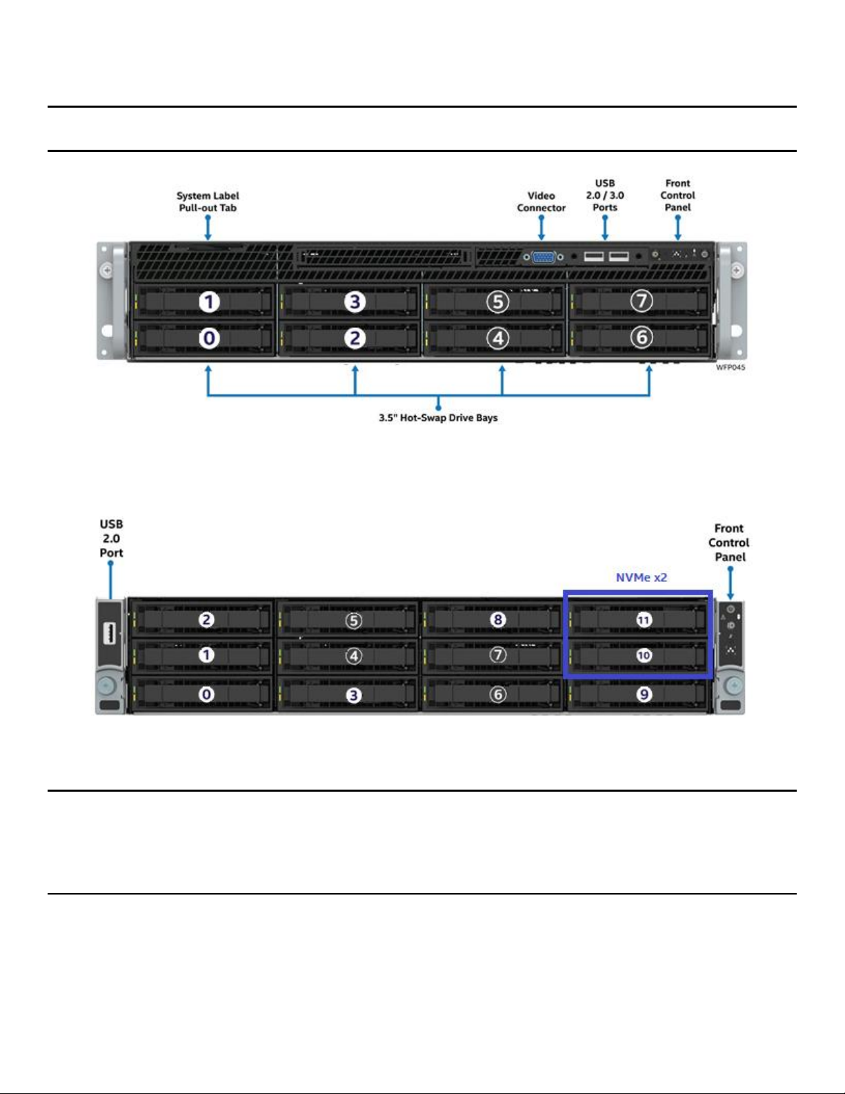
Intel® Server System R2000WF Product Family Technical Product Specification
The 2U product family also includes options to support 8 and 12 front mounted 3.5” drives. System
configured with eight devices also include front panel I/O.
Note: 3.5” drive trays in the 8 and 12 drive system configurations are capable of supporting 3.5” drives or
2.5” SSDs with the supplied device bracket.
Figure 42. 3.5" drive bay, 8 drive configuration
Figure 43. 3.5” drive bay, 12 drive configuration
Note: Drive numbering in the system illustrations is for general reference only. Actual drive numbering is
dependent on SAS / SATA controller configuration and how they are cabled to the backplane. On the
backside of each installed backplane is a multi-port mini-SAS HD data connector for each set of four
SATA/SAS drives. Backplanes that support PCIe NVMe drives will also include a single PCIe OCuLink
connector for each NVMe drive supported on the backplane.
70
Page 71

Intel® Server System R2000WF Product Family Technical Product Specification
6.2 Hot Swap Drive Carriers
Each SAS/SATA/NVMe* drive that interfaces with a backplane is mounted to a tool-less hot swap drive
carrier.
Drive carriers include a latching mechanism used to assist with drive extraction and drive insertion.
Figure 44. Drive carrier removal
Note: To ensure proper system air flow requirements, all front drive bays must be populated with a drive
carrier. Drive carriers must be installed with either a drive or supplied drive blank.
There are drive carriers to support 2.5” drives and 3.5” drives. Drive blanks used with the 3.5” drive carrier
can also be used to mount a 2.5” SSD.
Figure 45. 2.5" SSD mounted to 3.5" drive carrier
71
Page 72

Intel® Server System R2000WF Product Family Technical Product Specification
Amber
LED State
Drive Status
Off
No access and no fault
Solid on
Hard drive fault has occurred
1 Hz blinking
RAID rebuild in progress
2 Hz blinking
Locate (identify)
Green
Condition
Drive Type
LED Behavior
Power on with no drive activity
SAS/NVMe*
LED stays on
SATA
LED stays off
Power on with drive activity
SAS/NVMe*
LED blinks off when processing a command
SATA
LED blinks on when processing a command
Power on and drive spun down
SAS/NVMe*
LED stays off
SATA
LED stays off
Power on and drive spinning up
SAS/NVMe*
LED blinks
SATA
LED stays off
Amber
LED State
Drive Status
Off
No fault, OK
4 Hz blinking
Locate (identify)
Solid on
Fault/fail
1 Hz blinking
Rebuild
Amber status LED
Green activity LED
2.5” only
drive tray
Amber status LED
Green activity LED
2.5” / 3.5”
drive tray
Note: Due to degraded performance and reliability concerns, the use of the 3.5” drive blank as a 2.5” drive
bracket is intended to support SSD type storage devices only. Installing a 2.5” hard disk drive into the 3.5”
drive blank cannot be supported.
Each drive carrier includes separate LED indicators for drive activity and drive status. Light pipes integrated
into the drive carrier assembly direct light emitted from LEDs mounted next to each drive connector on the
backplane to the drive carrier faceplate, making them visible from the front of the system.
Figure 46. Drive tray LED identification
Table 49. Drive status LED states
Table 50. Drive activity LED states
72
Table 51. PCIe* SSD drive status LED states
Page 73

Intel® Server System R2000WF Product Family Technical Product Specification
Peripheral power
(Peripheral PWR)
HSBP power
(HSBP_PWR)
Note: The drive activity LED is driven by signals coming from the drive itself. Drive vendors may choose to
operate the activity LED different from what is described in the table above. Should the activity LED on a
given drive type behave differently than what is described, customers should reference the drive vendor
specifications for the specific drive model to determine the expected drive activity LED operation.
6.3 Peripheral Power Sources
Power for all backplanes and peripheral storage devices is drawn from two power connectors labeled as
“HSBP_PWR” and “Peripheral PWR” on the server board as illustrated below.
Figure 47. Server board peripheral power connectors
HSBP power – The hot swap backplane power connector provides power for all front mounted
backplane options. Appropriate power cables to support any given backplane option are included
with the given system model or given backplane accessory kit. For the HSBP power connector pinout, see Table 35.
Peripheral power – The peripheral power connector is used to provide power to various add-in
options including: internal mounted SSD drives, and the 2 x 2.5” rear mount hot swap backplane
accessory kit. Appropriate power cables for supported peripheral options are included with the given
system model or given accessory kit option.
6.4 Hot Swap Backplane Support
The 2U system has support for several backplane options.
For 2.5” drives, available backplane options include:
8 x 2.5” drive combo backplane with support for SAS/SATA/NVMe*
8 x 2.5” drive dual port SAS backplane
2 x 2.5” drive rear mount SATA SSD backplane
For 3.5” drives, available options include:
8 x 3.5” drive backplane with support for SAS/SATA
12 x 3.5” drive backplane with support SAS/SATA and up to two NVMe drives
73
Page 74

Intel® Server System R2000WF Product Family Technical Product Specification
The 3.5” drive backplanes are fixed mounted to the back of the drive bay within the chassis (as shown in the
following diagram).
Figure 48. 3.5" backplane placement
All 2.5” drive backplane options are mounted to a drive bay module that either slide into open bays within
the front of the chassis or is mounted to a fixed mount bay in the rear of the chassis as shown below.
Figure 49. 2.5" drive bay module placement options
Backplanes include the following features:
12 Gb SAS and 6 Gb SAS/SATA or slower support
Drive interface connectors
o 29-pin SFF-8680 – SATA/SAS only
o 68-pin SFF-8639 – SATA/SAS/NVMe – NVMe compatible backplanes only
Hot swap drive support
Cable connectors
o SFF-8643 Mini-SAS HD – 2.5” and 3.5” backplanes – 12 Gb SAS capable
o OCuLink PCIe* interface – NVMe compatible backplanes only
o 1x5-pin connector – I2C interface for device status communication to the BMC over slave
SMBus
o 2x2-pin connector – power
SGPIO SFF-8485 interface embedded within the sideband of the mini-SAS HD connectors
HSBP microcontroller – Cypress* CY8C22545-24AXI PSoC* Programmable System-on-Chip device
74
Page 75

Intel® Server System R2000WF Product Family Technical Product Specification
LEDs to indicate drive activity and status for each attached device
Device presence detect inputs to the microcontroller
5 V VR for devices
3.3 V VR for microcontroller
In-application microcontroller firmware updateable over the I2C interface
FRU EEPROM support
Temperature sensor through the use of a TMP75 (or equivalent) thermistor implementation with the
microcontroller
6.4.1 SGPIO Functionality
Backplanes include support for a SFF-8485 compliant SGPIO interface used to activate the status LED. This
interface is also monitored by the microcontroller for generating FAULT, IDENTIFY, and REBUILD registers
that in turn are monitored by the server board BMC for generating corresponding SEL events.
6.4.2 I2C Functionality
The microcontroller has a master/slave I2C connection to the server board BMC. The microcontroller is not
an IPMB compliant device. The BMC generates SEL events by monitoring registers on the HSBP
microcontroller for DRIVE PRESENCE, FAULT, and RAID REBUILD in progress.
6.5 8 x 2.5” Drive SATA/SAS/NVMe* Combo Backplane
This section applies to the 8 x 2.5” drive SAS/SATA/NVMe combo backplane (iPC – F2U8X25S3PHS).
All system SKUs capable of supporting 2.5” drives will include one or more eight drive backplanes capable of
supporting 12 Gb/sec SAS, 6 Gb/sec SATA drives, and PCIe NVMe* drives.
The front side of the backplane includes 68-pin SFF-8639 drive interface connectors, each capable of
supporting SAS, SATA, or NVMe drives. The connectors are numbered 0 through 7.
Figure 50. 8 x 2.5" SAS/SATA/NVMe* hot swap backplane, front side
The backside of the backplane includes two multi-port mini-SAS HD connectors labeled SAS/SATA_0-3 and
SAS/SATA_4-7, and eight PCIe OCuLink connectors, each labeled PCIe SSD#, where # = 0 -7, one connector
for each installed NVMe drive.
75
Page 76
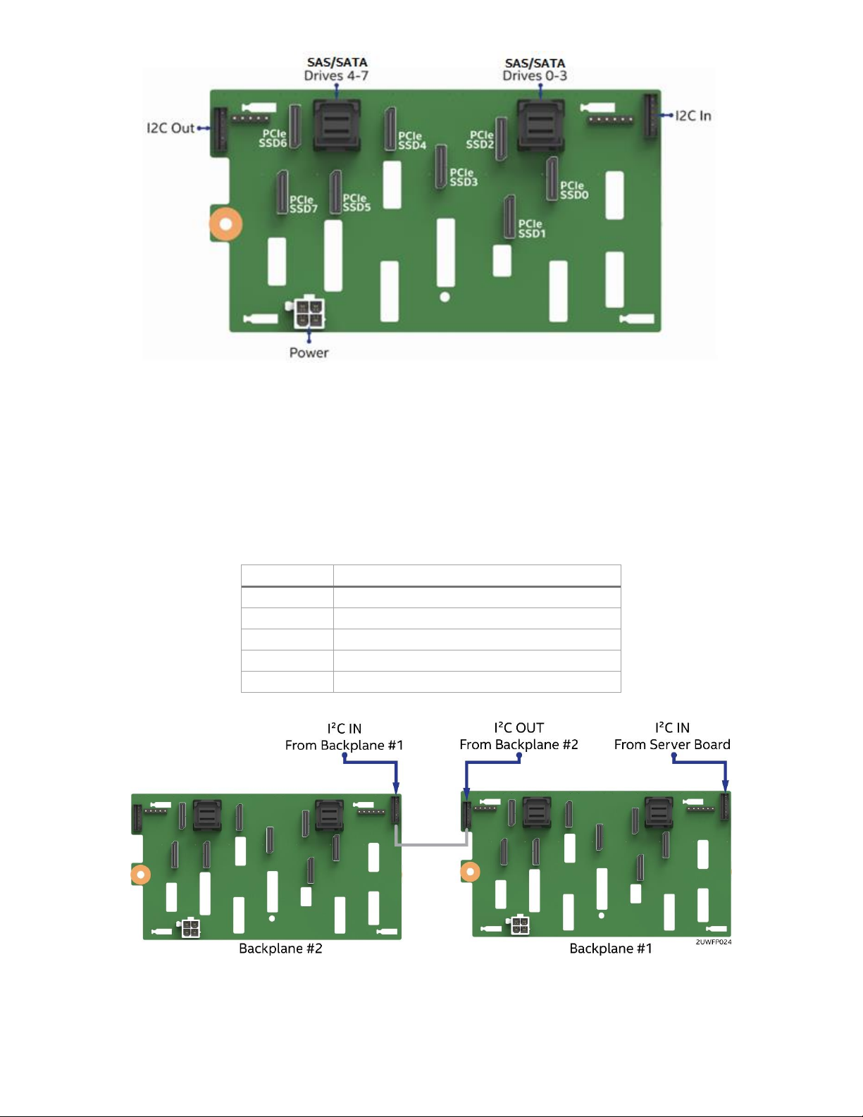
Intel® Server System R2000WF Product Family Technical Product Specification
Pin
Signal
1
SMB_3V3SB_DAT
2
GND
3
SMB_3V3SB_CLK
4
SMB_ADD0
5
SMB_ADD1
Figure 51. 8 x 2.5" SAS/SATA/NVMe* hot swap backplane, back side
I2C cable connectors – The backplane includes two 1x5 cable connectors (labeled I2C_IN and I2C_OUT)
used as a management interface between the server board and the installed backplanes. In systems
configured with multiple backplanes, a short jumper cable is attached between backplanes, with connector A
used on the first board and connector D used on the second board, extending the SMBus to each installed
backplane.
Table 52. I2C cable connector pin-out
Multi-port mini-SAS HD cable connectors – The backplane includes two multi-port mini-SAS HD cable
connectors (labeled PORT 0-3 and PORT 4-7), each providing SGPIO and I/O signals for up to four SAS/SATA
devices installed in the hot swap drive bay. Input cables can be routed from matching connectors on the
76
Figure 52. 8 x 2.5" dual port SAS backplane, back side
Page 77
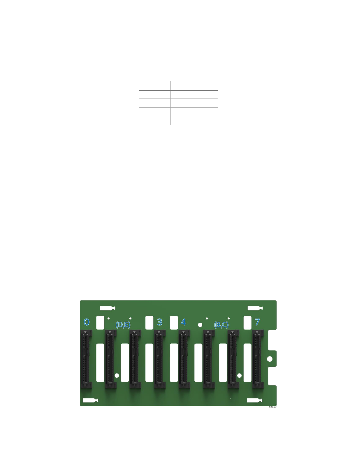
Intel® Server System R2000WF Product Family Technical Product Specification
Pin
Signal
1
GND
2
GND
3
P12V
4
P12V
server board (on-board SATA only), from installed add-in SAS/SATA RAID cards, or from an optionally
installed SAS expander card for drive configurations of greater than eight hard drives.
Power harness connector– The backplane includes a 2x2 connector supplying power to the backplane.
Power is routed to each installed backplane via a multi-connector power cable harness from the server
board.
Table 53. Power harness connector pin-out
PCIe OCuLink* Connectors The backplane has support for up to eight (8) NVMe SFF SSDs. The backside of
the backplane includes eight OCuLink* cable connectors, one for each drive connector on the front side of
the backplane. Each installed NVMe drive must have PCIe signals cabled to the appropriate backplane
OCuLink connector from any of the following PCIe signal sources:
Available onboard PCIe* OCuLink connectors on the server board
Optional PCIe 4 or 8 Port Switch Add-in Card
Optional Tri-Mode Raid Module or Add-in Card
Optional PCIe 4 port Retimer Add-in Card
See section 7.4 for NVMe support information.
6.6 8 x 2.5” Drive Dual Port SAS Backplane
This section applies to the 8 x 2.5” drive dual port SAS backplane (accessory kit iPC – A2U8X25S3DPDK).
With the 8 x drive dual port backplane accessory kit installed, the server can support up to eight dual port
SAS drives. The front side of the backplane includes 8 x 29-pin drive interface connectors, each capable of
supporting 12 Gb SAS or 6 Gb SAS/SATA. The connectors are numbered 0 through 7. Signals for each set of
four drive connectors (0-3 and 4-7), are routed to a pair of mini-SAS HD connectors on the back side of the
backplane, one for the primary port and one for the secondary port.
Figure 53. 8 x 2.5" dual port SAS backplane, front side
77
Page 78
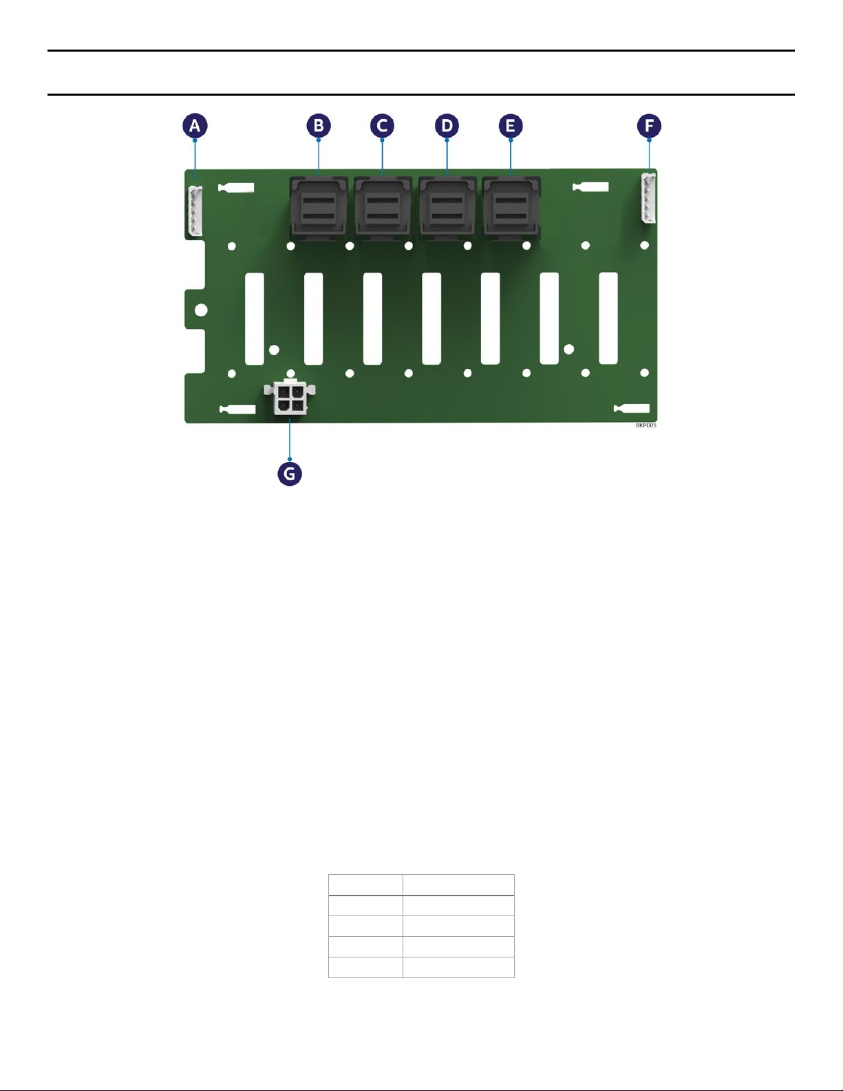
Intel® Server System R2000WF Product Family Technical Product Specification
Pin
Signal
1
GND
2
GND
3
P12V
4
P12V
A – I2C-out cable connector for multi-backplane support
B – Ports 4-7 (secondary) mini-SAS HD cable connector
C – Ports 4-7 (primary) mini-SAS HD cable connector
D – Ports 0-3 (secondary) mini-SAS HD cable connector
E – Ports 0-3 (primary) mini-SAS HD cable connector
F – I2C-in cable connector – from server board or other backplane
G – Power connector
Note: Letters in parenthesis denote references to connectors on the back side of the backplane as illustrated
in Figure 52.
Figure 54 . 8 x 2.5" dual port SAS backplane, Back side
Multi-port mini-SAS HD cable connectors (connectors B and C) – Primary and secondary port connectors
for drives 4-7. Cables can be routed from matching connectors on the server board, from installed add-in
SAS/SATA RAID cards, or from optionally installed SAS expander cards for drive configurations of greater
than eight hard drives.
Multi-port mini-SAS cable connectors (connectors D and E) – Primary and secondary port connectors for
drives 0-3. Cables can be routed from matching connectors on the server board, from installed add-in
SAS/SATA RAID cards, or from optionally installed SAS expander cards for drive configurations of greater
than eight hard drives.
Power harness connector (connector G) – The backplane includes a 2x2 connector supplying power to the
backplane. Power is routed to each installed backplane via a multi-connector power cable harness from the
server board.
Table 54. Power harness connector pin-out
78
Page 79
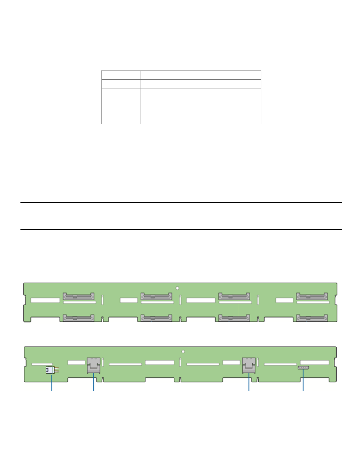
Intel® Server System R2000WF Product Family Technical Product Specification
Pin
Signal
1
SMB_3V3SB_DAT
2
GND
3
SMB_3V3SB_CLK
4
SMB_ADD0
5
SMB_ADD1
A B C
D
0 (C)
1 (C)
2 (C)
3 (C)
4 (B)
5 (B)
6 (B)
7 (B)
A – Power connectors
B – Ports 4-7 mini-SAS HD cable connector
Note: Letters in parenthesis denote references to connectors on the back side of the backplane.
C – Ports 0-3 mini-SAS HD cable connector
D – I2C connector
I2C cable connectors (connectors A and F) – The backplane includes two 1x5 cable connectors used as a
management interface between the server board and the installed backplanes. In systems configured with
multiple backplanes, a short jumper cable is attached between backplanes, with connector A used on the
first board and connector F used on the second board, extending the SMBus to each installed backplane.
Table 55. I2C cable connector pin-out
6.7 8 x 3.5” Drive Hot-Swap Backplane Overview
This section applies to the 8 x 3.5” drive hot-swap backplane (iPC – F2U8X35S3HSBP).
2U server systems that support the 8 drive backplane have support for the following drive form factors:
3.5” hard drives
2.5” SSDs using the included drive blanks as a drive bracket
Note: Due to degraded performance and reliability concerns, the use of the 3.5” drive blank as a 2.5” drive
bracket is intended to support SSD type storage devices only. Installing a 2.5” hard disk drive into the 3.5”
drive blank cannot be supported.
This backplane has support for up to 6Gb/s SATA drives or up to 12 Gb/s SAS drives
Mounted on the front side of the backplane are eight 29-pin (SFF-8482) drive connectors. On the backside of
the backplane are connectors for power, I2C management, and SAS/SATA data.
Figure 55. 8 x 3.5" HSBP Connector Identification
79
Page 80
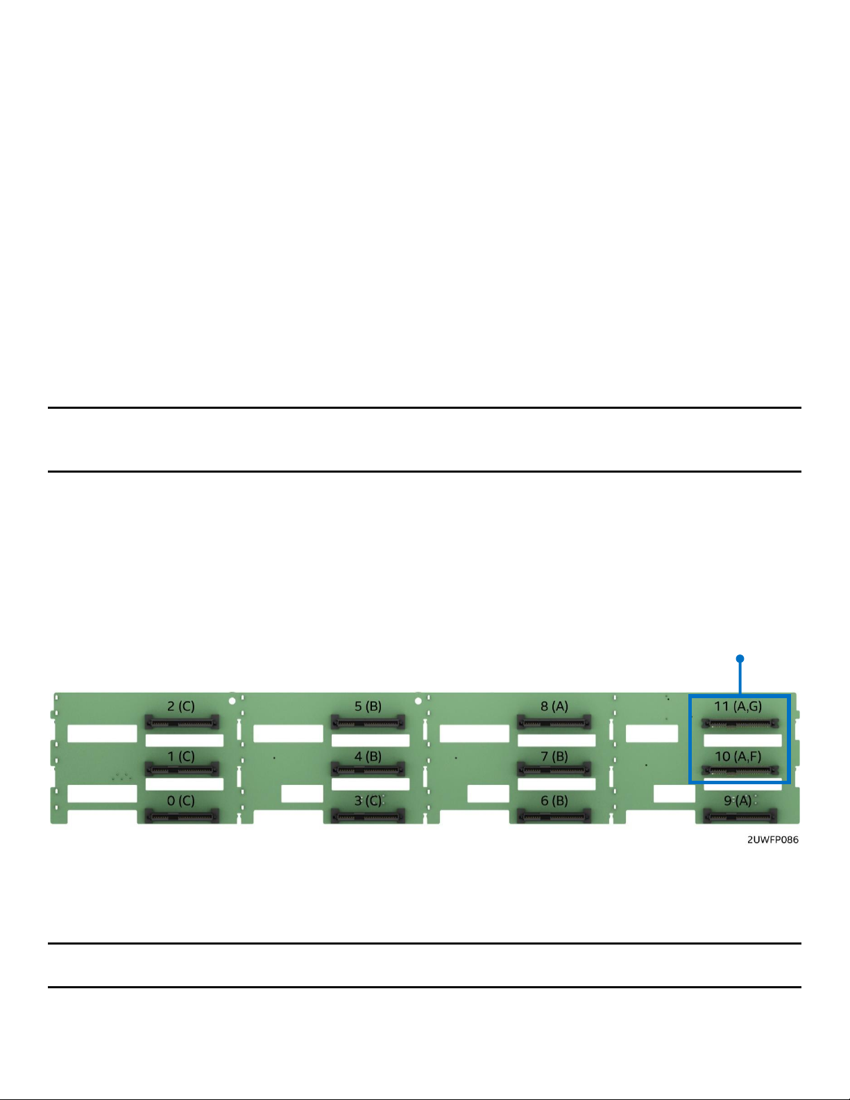
Intel® Server System R2000WF Product Family Technical Product Specification
NVMe Compatible
Power harness connector (connector A) – The backplane includes a 2x2 connector supplying power to the
backplane. Power is routed to the backplane via a power cable harness from the server board
Multi-port mini-SAS HD cable connectors (connectors B and C) – The 8 x drive backplane includes two
multi-port mini-SAS cable connectors, each providing SGPIO and I/O signals for four SAS/SATA hard drives
on the backplane. Cables can be routed from matching connectors on the server board, from add-in
SAS/SATA RAID cards, or from an optionally installed SAS expander card. Each mini-SAS HD connector
includes a silk-screen identifying which drives the connector supports: drives 0-3 and drives 4-7.
I2C cable connector (connector D) – The backplane includes a 1x5 cable connector used as a management
interface to the server board
6.8 12 x 3.5” Drive Hot-Swap Backplane Overview
This section applies to the 12 x 3.5” drive hot-swap backplane (iPC – F2U12X35S3PH).
2U server systems that support the 12 drive backplane have support for the following drive form factors:
3.5” hard drives
2.5” SSDs using the included drive blanks as a drive bracket
Note: Due to degraded performance and reliability concerns, the use of the 3.5” drive blank as a 2.5” drive
bracket is intended to support SSD type storage devices only. Installing a 2.5” hard disk drive into the 3.5”
drive blank cannot be supported.
Drive technologies supported include:
6 Gb/s SATA
12 Gb/s SAS
PCIe* NVMe (up to 2 drives)
Mounted on the front side of the backplane are ten 29-pin (SFF-8482) drive connectors supporting
SAS/SATA drives only, and two 68-pin SFF-8639 drive connectors supporting SAS/SATA/NVMe drives.
Figure 56. 12 x 3.5" hot swap backplane, front side
On the backside of the backplane are connectors for power, I2C management, SAS/SATA data, and PCIe
NVMe.
Note: Letters in parenthesis denote references to connectors on the back side of the backplane as illustrated
in Figure 57.
80
Page 81
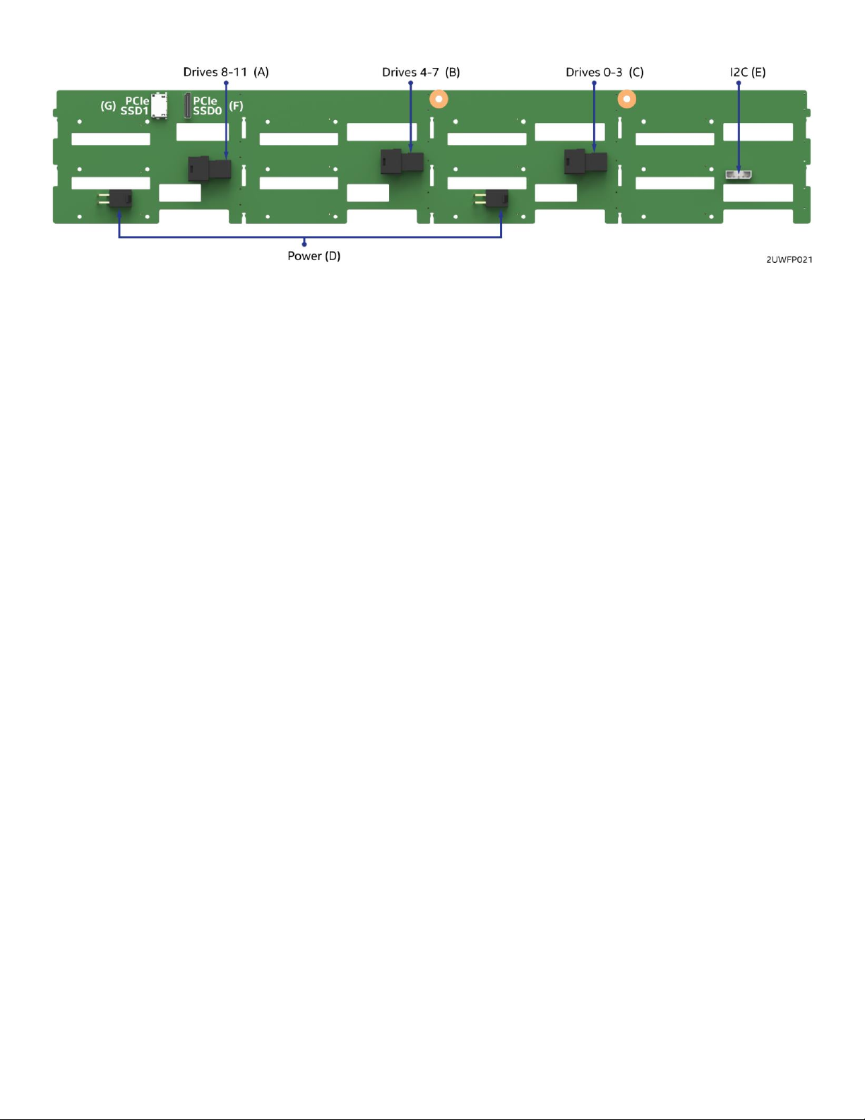
Intel® Server System R2000WF Product Family Technical Product Specification
A – Ports 8-11 mini-SAS HD cable connector
B – Ports 4-7 mini-SAS HD cable connector
C – Ports 0-3 mini-SAS HD cable connector
D – Power connectors
E – I2C connector
F
G – PCIe* SSD connector SSD1
– PCIe* SSD connector SSD0
Figure 57. 12 x 3.5" HSBP connector identification
Multi-port mini-SAS HD cable connectors (connectors A, B, and C) – The 12 x drive backplane includes
three multi-port mini-SAS cable connectors, each providing SGPIO and I/O signals for four SAS/SATA drives
on the backplane. Cables can be routed from matching connectors on the server board, from add-in
SAS/SATA RAID cards, or from an optionally installed SAS expander card. Each mini-SAS HD connector
includes a silk-screen identifying which drives the connector supports: drives 0-3, drives 4-7, and drives
8-11.
Power harness connector (connector D) – The backplane includes a 2x2 connector supplying power to the
backplane. Power is routed to the backplane via a power cable harness from the server board
I2C cable connectors (connector E) – The backplane includes a 1x5 cable connector used as a management
interface to the server board.
PCIe SSD connector (connectors F and G) – The backplane includes two PCIe OCuLink cable connectors
(labeled PCIe SSD0 and PCIe SSD1), each providing support for one NVMe drive.
6.9 2 x 2.5” Hot Swap Drive Bay Accessory Kit
This section applies to the 2 x 2.5” hot swap drive bay accessory kit (iPC – A2UREARHSDK).
The 2U product family provides the option to support two 6 Gb/sec hot swap SATA SSDs installed to a
modular drive bay mounted in the back of the system.
81
Page 82

Intel® Server System R2000WF Product Family Technical Product Specification
Figure 58. 2 x 2.5" rear mount backplane kit placement
Supported SATA SSDs must not exceed the following power and thermal limits:
One or two SATA SSDs supporting up to 4 W per device with a case temperature rating of 70 °C
One or two SATA SSDs supporting up to 1.5 W per device with a case temperature rating of 60 °C
Note: The maximum supported SSD power and thermal limits documented above were derived based on
thermal testing using a maximum system configuration with fan redundancy support operating at ambient
input air temp of 35 °C. The test system was based on the system models utilizing a maximum number of
front and rear drive storage devices – 12 x 3.5” or 24 x 2.5” in the front and 2 x 2.5” in the back.
Because of thermal limits in this area of the chassis, the rear hot swap drive bay option cannot support hard
disk drives in any system configuration.
By lowering the maximum supported ambient air temperature to 27 °C, and limiting the system configuration
to support 8 or 16 devices up front and no storage devices configured on the air duct, supported SATA SSDs
must not exceed the following power and thermal limits:
One or two SATA SSDs supporting up to 6.4 W per device with a case temperature rating of 70 °C
One or two SATA SSDs supporting up to 3.6 W per device with a case temperature rating of 60 °C
The backplane includes several connectors and a jumper block, as defined in the following illustrations.
82
Page 83
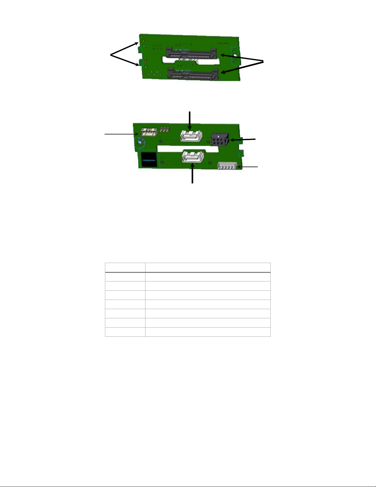
Intel® Server System R2000WF Product Family Technical Product Specification
Pin
Signal
1
GND
2
SAS_SATA_TX_P
3
SAS_SATA_TX_N
4
GND
5
SAS_SATA_RX_N
6
SAS_SATA_RX_P
7
GND
SATA drive
connectors
Activity and
status LEDs
Drive 0
Drive 1
Power
HSBP_I2C
SGPIO
Figure 59. 2 x 2.5" hot swap backplane
Activity/status LEDs – The backplane includes LEDs for both activity and status for each drive.
SATA drive connectors – The backplane includes two hot-swap capable SATA drive connectors
7-pin SATA cable connectors – The backplane includes two 7-pin connectors capable of supporting
a SATA interface. The following table defines the pin-out for these connectors.
Table 56. 7-pin SATA cable connector pin-out
83
Page 84

Intel® Server System R2000WF Product Family Technical Product Specification
Pin
Signal
1
P5V 2 P5V
3
GND
4
P12V
5
P3V3
6
GND
Pin
Signal
1
SMB_3V3SB_DAT
2
GND
3
SMB_3V3SB_CLK
4
SMB_ADD0
5
SMB_ADD1
Pin
Signal
1
SGPIO_CLOCK
2
SGPIO_LOAD
3
GND
4
SGPIO_DATAOUT
5
SGPIO_ DATAIN
Power connector – The backplane includes a 2x3 pin power connector. The following table defines
the pin-out for this connector:
Table 57. Power connector pin-out
I2C connector – The backplane includes a 1x5 pin I2C connector. This connector is cabled to a
matching HSBP I2C connector on the server board and is used as a communication path to the
onboard BMC. The following table defines the pin out for this connector.
Table 58. I2C connector pin-out
SGPIO connector – The backplane includes a 1x5 pin SGPIO connector. When the backplane is cabled to
the on-board SATA ports, this connector is cabled to a matching SGPIO connector on the server board
and provides support for drive activity and fault LEDs. The following table defines the pin out for this
connector.
Table 59. SGPIO connector pin-out
84
Page 85
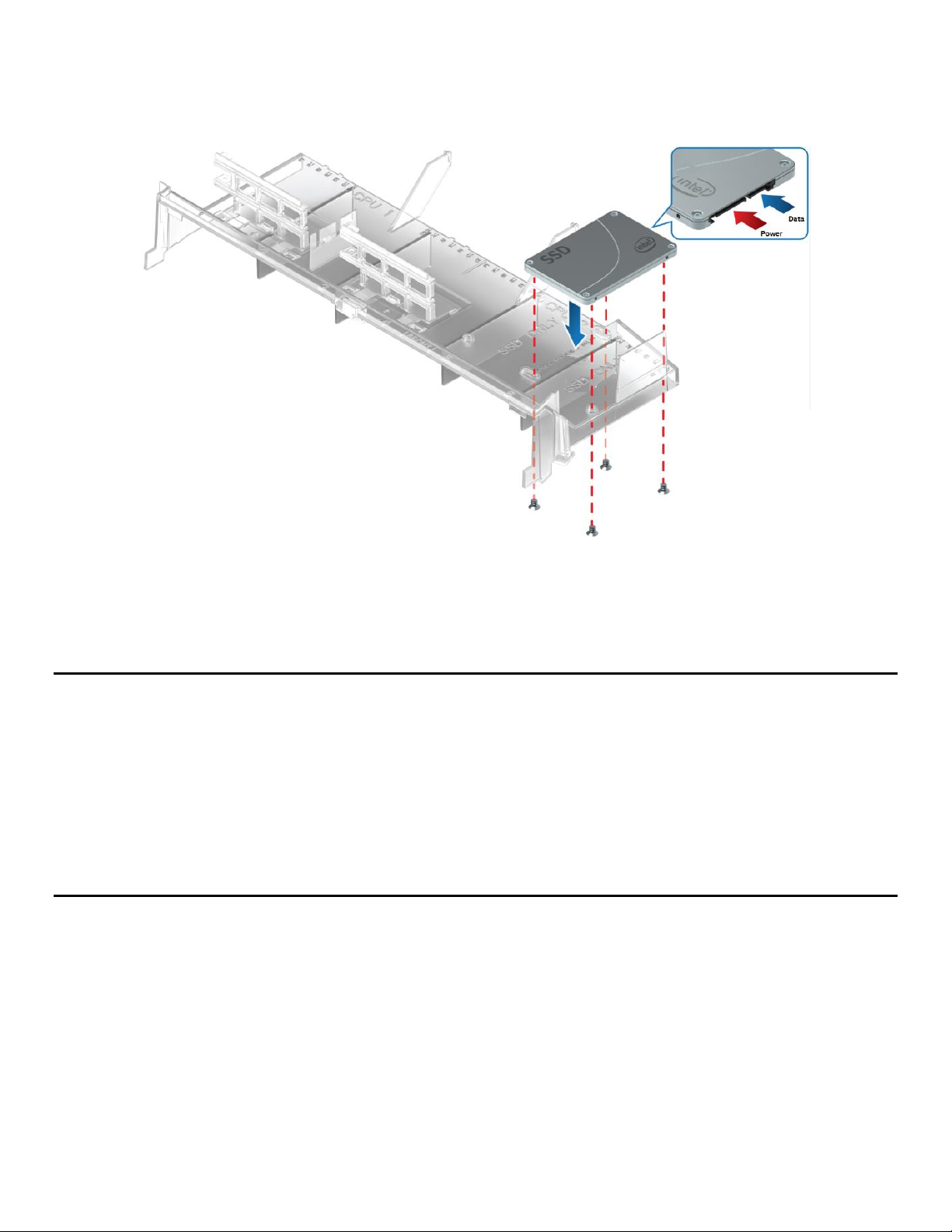
Intel® Server System R2000WF Product Family Technical Product Specification
6.10 Internal Fixed Mount Solid State Drive (SSD) Support
The system can support up to two internal fixed mount 2.5” solid state drives (SSDs). Each drive is attached
to the top side of the air duct as illustrated below.
Figure 60. 2.5" Solid state drive (SSD) mounting option
SSDs mounted to the air duct must not exceed the following power and thermal limits.
One or two SATA SSDs supporting up to 6.2 W per device with a case temperature rating of 70 °C
One or two SATA SSDs supporting up to 2.3 W per device with a case temperature rating of 60 °C
Note: Maximum supported SSD power and thermal limits were derived based on thermal testing using a
maximum system configuration with fan redundancy support using a maximum ambient temperature of
35 °C. The test system was based on the system models utilizing a maximum number of front and rear drive
storage devices – 12 x 3.5” or 24 x 2.5” in the front and 2 x 2.5” in the back. Higher SSD power and thermal
limits maybe possible with system configurations that support 8 or 16 devices up front, no storage devices
configured in back, and lowering the maximum operating ambient temperature.
Note: Mounting standard hard disk drives to the CPU air duct is not a supported configuration. Mounting
hard disk drives to the CPU air duct may cause data loss, performance degradation, and premature drive
failures.
A 2x3 pin power connector on the server board labeled “Peripheral PWR” is designed to provide power to
both SSDs or a single SSD and an optical drive. Using the supplied power harness, one power lead is routed
to the optical drive bay, and two longer power leads are routed to the SSDs. SATA signals for one SSD and
one optical drive or two SSDs are cabled from the two white 7-pin AHCI SATA connectors on the server
board.
85
Page 86
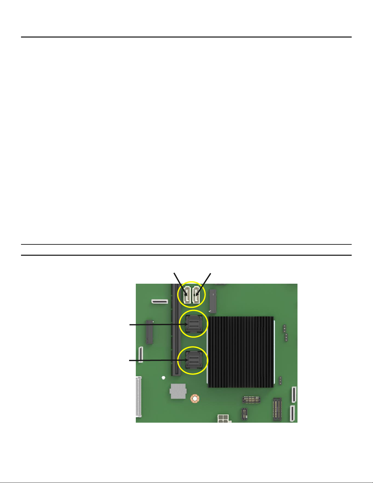
Intel® Server System R2000WF Product Family Technical Product Specification
SATA ports 0-3
SATA ports 4-7
sSATA port 4
sSATA port 5
7. Storage Controller Options Overview
The Intel® Server System R2000WF product family has support for a variety of storage controller and storage
device options including:
Onboard SATA support
Embedded software RAID support
M.2 SSD support
NVMe* SFF SSD support
Intel® Integrated RAID Modules support
7.1 Onboard SATA Support
The server board utilizes two chipset embedded AHCI SATA controllers, identified as SATA and sSATA,
providing for up to ten 6 Gb/sec Serial ATA (SATA) ports.
The AHCI sSATA controller provides support for up to 4 SATA ports on the server board:
• Two ports accessed via two white single port 7-pin connectors labeled “sSATA-4” and “sSATA-5” on the
server board
• Two ports (sSATA 1 and sSATA 2) via two M.2 SSD connectors
The AHCI SATA controller provides support for up to 8 SATA ports on the server board: (S2600WFT &
S2600WF0 boards only)
• Four ports from the Mini-SAS HD (SFF-8643) connector labeled “SATA Ports 0-3” on the server board
• Four ports from the Mini-SAS HD (SFF-8643) connector labeled “SATA Ports 4-7” on the server board.
Note: The onboard SATA controllers are not compatible with and cannot be used with SAS expander cards.
86
Figure 61. Onboard storage support features
Page 87

Intel® Server System R2000WF Product Family Technical Product Specification
Feature
Description
AHCI Mode
RAID Mode
Intel® RSTe
RAID Mode
Intel® ESRT2
Native Command
Queuing (NCQ)
Allows the device to reorder commands for more
efficient data transfers
Supported
Supported
Auto Activate for DMA
Collapses a DMA Setup then DMA Activate sequence
into a DMA Setup only
Supported
Supported
Hot Plug Support
Allows for device detection without power being applied
and ability to connect and disconnect devices without
prior notification to the system
Supported
Supported
Asynchronous Signal
Recovery
Provides a recovery from a loss of signal or establishing
communication after hot plug
Supported
Supported
6 Gb/s Transfer Rate
Capable of data transfers up to 6 Gb/s
Supported
Supported
Supported
ATAPI Asynchronous
Notification
A mechanism for a device to send a notification to the
host that the device requires attention
Supported
Supported
Host & Link Initiated
Power Management
Capability for the host controller or device to request
Partial and Slumber interface power states
Supported
Supported
Staggered Spin-Up
Enables the host the ability to spin up hard drives
sequentially to prevent power load problems on boot
Supported
Supported
Supported
Command Completion
Coalescing
Reduces interrupt and completion overhead by allowing
a specified number of commands to complete and then
generating an interrupt to process the commands
Supported
N/A
SATA Controller
sSATA Controller
Supported
AHCI
AHCI
Yes
AHCI
Disabled
Yes
AHCI
Intel® RSTe
Yes
AHCI
Intel® Embedded Server RAID Technology 2
Microsoft Windows* only
Disabled
AHCI
Yes
Disabled
Disabled
Yes
Disabled
Intel® RSTe
Yes
Disabled
Intel® Embedded Server RAID Technology 2
Yes
Intel® RSTe
AHCI
Yes
Intel® RSTe
Disabled
Yes
Intel® RSTe
Intel® RSTe
Yes
Intel® RSTe
Intel® Embedded Server RAID Technology 2
No
Intel® Embedded Server RAID Technology 2
AHCI
Microsoft Windows only
Intel® Embedded Server RAID Technology 2
Disabled
Yes
Intel® Embedded Server RAID Technology 2
Intel® RSTe
No
Intel® Embedded Server RAID Technology 2
Intel® Embedded Server RAID Technology 2
Yes
Table 60. SATA and sSATA controller feature support
The SATA controller and the sSATA controller can be independently enabled and disabled and configured
through the BIOS setup utility under the Mass Storage Controller Configuration menu screen. The following
table identifies supported setup options.
Table 61. SATA and sSATA controller BIOS setup utility options
87
Page 88

Intel® Server System R2000WF Product Family Technical Product Specification
7.1.1 Staggered Disk Spin-Up
Because of the high density of disk drives that can be attached to the Intel® C620 onboard AHCI SATA
controller and the sSATA controller, the combined startup power demand surge for all drives at once can be
much higher than the normal running power requirements and could require a much larger power supply for
startup than for normal operations.
In order to mitigate this and lessen the peak power demand during system startup, both the AHCI SATA
Controller and the sSATA Controller implement a Staggered Spin-Up capability for the attached drives. This
means that the drives are started up separately, with a certain delay between disk drives starting.
For the onboard SATA controller, staggered spin-up is an option – AHCI HDD Staggered Spin-Up – in the
Mass Storage Controller Configuration screen found in the BIOS setup utility.
7.2 Onboard SATA Software RAID Support
The server board includes support for two embedded SATA RAID options:
Intel® Rapid Storage Technology enterprise (Intel® RSTe) 5.0
Intel® Embedded Server RAID Technology 2 (ESRT2) 1.60
By default, onboard RAID options are disabled in BIOS setup. To enable onboard RAID support, access the
BIOS setup utility during POST. The onboard RAID options can be found under the sSATA Controller or
SATA Controller options under the following BIOS setup menu:
Advanced -> Mass Storage Controller Configuration
Figure 62. BIOS setup Mass Storage Controller Configuration screen
Note: RAID partitions created using either RSTe or ESRT2 cannot span across the two embedded SATA
controllers. Only drives attached to a common SATA controller can be included in a RAID partition.
88
Page 89

Intel® Server System R2000WF Product Family Technical Product Specification
7.2.1 Intel® Rapid Storage Technology Enterprise (Intel® RSTe) 5.0
Intel® Rapid Storage Technology enterprise (Intel® RSTe) offers several options for RAID to meet the needs of
the end user. AHCI support provides higher performance and alleviates disk bottlenecks by taking advantage
of the independent DMA engines that each SATA port offers in the chipset. Supported RAID levels include 0,
1, 5, and 10.
RAID 0 – Uses striping to provide high data throughput, especially for large files in an environment
that does not require fault tolerance.
RAID 1 – Uses mirroring so that data written to one disk drive simultaneously writes to another disk
drive. This is good for small databases or other applications that require small capacity but complete
data redundancy.
RAID 5 – Uses disk striping and parity data across all drives (distributed parity) to provide high data
throughput, especially for small random access.
RAID 10 – A combination of RAID 0 and RAID 1, consists of striped data across mirrored spans. It
provides high data throughput and complete data redundancy but uses a larger number of spans.
By using Intel RSTe, there is no loss of PCI resources (request/grant pair) or add-in card slot. Intel RSTe
functionality requires the following:
The embedded RAID option must be enabled in BIOS setup.
Intel RSTe option must be selected in BIOS setup.
Intel RSTe drivers must be loaded for the installed operating system.
At least two SATA drives needed to support RAID levels 0 or 1.
At least three SATA drives needed to support RAID level 5.
At least four SATA drives needed to support RAID level 10.
NVMe SSDs and SATA drives must not be mixed within a single RAID volume
With Intel RSTe software RAID enabled, the following features are made available:
A boot-time, pre-operating-system environment, text-mode user interface that allows the user to
manage the RAID configuration on the system. Its feature set is kept simple to keep size to a
minimum, but allows the user to create and delete RAID volumes and select recovery options when
problems occur. The user interface can be accessed by pressing <CTRL-I> during system POST.
Boot support when using a RAID volume as a boot disk. It does this by providing Int13 services when
a RAID volume needs to be accessed by MS-DOS applications (such as NT loader (NTLDR)) and by
exporting the RAID volumes to the system BIOS for selection in the boot order.
At each boot-up, a status of the RAID volumes provided to the user.
7.2.2 Intel® Embedded Server RAID Technology 2 (ESRT2) 1.60 for SATA
Intel® Embedded Server RAID Technology 2 (powered by LSI*) is a driver-based RAID solution for SATA that
is compatible with previous generation Intel® server RAID solutions. Intel Embedded Server RAID Technology
2 provides RAID levels 0, 1, and 10, with an optional RAID 5 capability depending on whether a RAID upgrade
key is installed.
Note: The embedded Intel Embedded Server RAID Technology 2 option has no RAID support for PCIe*
NVMe* SSDs.
Intel Embedded Server RAID Technology 2 is based on LSI* MegaRAID software stack and utilizes the system
memory and CPU.
Supported RAID levels include:
RAID 0: Uses striping to provide high data throughput, especially for large files in an environment that
does not require fault tolerance.
89
Page 90

Intel® Server System R2000WF Product Family Technical Product Specification
RAID 1: Uses mirroring so that data written to one disk drive simultaneously writes to another disk
drive. This is good for small databases or other applications that require small capacity but complete
data redundancy
RAID 10: A combination of RAID 0 and RAID 1, consists of striped data across mirrored spans. It
provides high data throughput and complete data redundancy but uses a larger number of spans.
Optional support for RAID Level 5
o Enabled with the addition of an optionally installed ESRT2 SATA RAID 5 Upgrade Key (iPN -
RKSATA4R5)
Figure 63. ESRT2 SATA RAID-5 upgrade key
o RAID 5: Uses disk striping and parity data across all drives (distributed parity) to provide high
data throughput, especially for small random access.
Intel Embedded Server RAID Technology 2 on this server board supports a maximum of six drives which is
the maximum onboard SATA port support.
The binary driver includes partial source files. The driver is fully open source using an MDRAID layer in
Linux*.
Note: RAID configurations cannot span across the two embedded AHCI SATA controllers.
90
Page 91

Intel® Server System R2000WF Product Family Technical Product Specification
7.3 M.2 SSD Support
The Intel® Server Board S2600WF product family includes two M.2 SSD connectors labeled
“M2_x4PCIE/sSATA_1” and “M2_x2PCIE/sSATA_2” on the server board as shown below.
Figure 64. M.2 module connector locations
Each M.2 connector can support PCIe* or SATA modules that conform to a 2280 (80 mm) form factor.
PCIe bus lanes for each connector are routed from the Intel chipset and can be supported in single processor
configurations.
The M.2 connector to the left of Riser Slot #1 is supported by PCIe x4 bus lanes and sSATA-1 from the
chipset embedded sSATA controller. The M.2 connector to the right of Riser Sot #1is supported by PCIe x2
bus lanes and sSATA-2 from the chipset embedded sSATA controller.
7.3.1 Embedded RAID Support
RAID support from embedded RAID options for server board mounted M.2 SSDs is defined as follows:
Neither Intel® ESRT2 nor Intel® RSTe have RAID support for PCIe* M.2 SSDs when installed to the M.2
connectors on the server board.
o Note: NVMe RAID support using Intel® RSTe VROC requires that the PCIe bus lanes be routed
directly from the CPU. On this server board, the PCIe bus lanes routed to the on-board M.2
connectors are routed from the Intel chipset (PCH).
o Note: The Intel® ESRT2 onboard RAID option does not support PCIe devices.
Both Intel® ESRT2 and Intel® RSTe provide RAID support for SATA devices
Neither embedded RAID option supports mixing of M.2 SATA SSDs and SATA hard drives within a
single RAID volume
Note: Storage devices used to create a single RAID volume created using either RSTe or ESRT2, cannot span
across the two embedded SATA controllers nor is mixing both SATA and NVMe devices within a single RAID
volume supported.
Open Source Compliance = Binary Driver (includes Partial Source files) or Open Source using MDRAID
layer in Linux*
91
Page 92
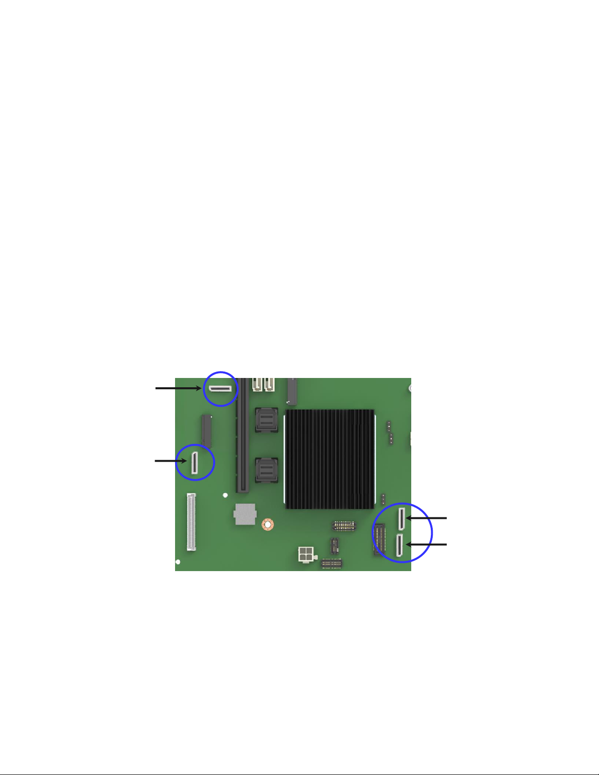
Intel® Server System R2000WF Product Family Technical Product Specification
PCIe SSD1
(CPU 1)
PCIe SSD0
(CPU 1)
PCIe SSD3
(CPU 2)
PCIe SSD2
(CPU 2)
7.4 PCIe NVMe* Drive Support
Several system models within the Intel® Server System R2000WF product family have support for PCIe
NVMe drives installed into the front drive bays. For system models supporting 12x3.5” drives, the front drive
bay can support up to two (2) NVMe drives. For system models supporting from one up to three 8x2.5”
combo backplanes, the front drive bay can support from one (1) up to eight (8) NVMe drives per installed
backplane.
Each installed NVMe drive must have its own PCIe interface as cabled to the backplane from one or more of
the following PCIe signal sources:
Onboard PCIe OCuLink connectors on the server board
4-port PCIe 3.0 x8 Switch add-in card (accessory kit iPC – AXXP3SWX08040)
8-port PCIe 3.0 x8 Switch add-in card (accessory kit iPC – AXXP3SWX08080)
4-port PCIe 3.0 x16 retimer add-in card (accessory kit iPC – AXXP3RTX16040)
Intel® Integrated RAID Modules with tri-mode support
7.4.1 Onboard PCIe* OCuLink Connectors
The server board provides four (4) onboard PCIe* OCuLink* connectors, each supporting a x4 PCIe signaling
interface. When cabled to the backplane, each connector provides the PCIe interface to a single installed
NVMe drive on the backplane.
PCIe* signals for onboard OCuLink connectors “PCIe_SSD0” and “PCIe_SSD1” are routed directly from
CPU_1 and PCIe signals for OCuLink connectors “PCIe_SSD2” and “PCIe_SSD3” are directly routed from
CPU_2..
Figure 65. Onboard OCuLink connectors
7.4.2 Intel® Volume Management Device (Intel® VMD) for NVMe*
Intel® Volume Management Device (Intel® VMD) is hardware logic inside the processor root complex to help
manage PCIe* NVMe* SSDs. It provides robust hot plug support and status LED management. This allows
servicing of storage system NVMe SSD media without fear of system crashes or hangs when ejecting or
inserting NVMe SSD devices on the PCIe bus.
92
Page 93
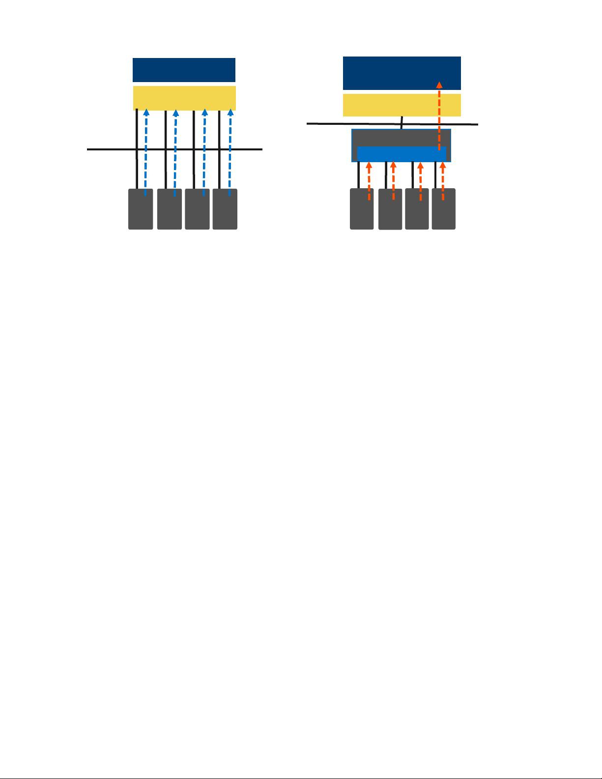
Intel® Server System R2000WF Product Family Technical Product Specification
Storage bus event/error handled by
BIOS or OS.
NVMe* Support w/o Intel® VMD
NVMe* driver
PCIe*
NVMe*
SSDs
OS PCI bus driver
Storage bus event/error handled by
storage driver.
Intel® VMD-enabled
NVMe* driver
OS PCI bus driver
PCIe*
NVMe*
SSDs
Processor
NVMe* Storage with Intel® VMD
Intel® VMD
Figure 66. NVMe* storage bus event/error handling
Intel® VMD handles the physical management of NVMe storage devices as a standalone function but can be
enhanced when Intel® VROC support options are enabled to implement RAID based storage systems. See
section 7.4.3 for more information.
Hardware is integrated inside the processor PCIe* root complex.
Entire PCIe* trees are mapped into their own address spaces (domains).
Each domain manages x16 PCIe* lanes.
Can be enabled/disabled in BIOS setup at x4 lane granularity.
Driver sets up/manages the domain (enumerate, event/error handling)
May load an additional child device driver that is Intel VMD aware.
Hot plug support - hot insert array of PCIe* SSDs.
Support for PCIe* SSDs and switches only (no network interface controllers (NICs), graphics cards,
etc.)
Maximum of 128 PCIe* bus numbers per domain.
Support for MCTP over SMBus only.
Support for MMIO only (no port-mapped I/O).
Does not support NTB, Quick Data Tech, Intel® Omni-Path Architecture, or SR-IOV.
Correctable errors do not bring down the system.
Intel® VMD only manages devices on PCIe* lanes routed directly from the processor. Intel® VMD
cannot provide device management on PCI lanes routed from the chipset (PCH)
When Intel VMD is enabled, the BIOS does not enumerate devices that are behind Intel VMD. The
Intel VMD-enabled driver is responsible for enumerating these devices and exposing them to the
host.
Intel® VMD supports hot-plug PCIe* SSDs connected to switch downstream ports. Intel® VMD does
not support hot-plug of the switch itself.
7.4.2.1 Enabling Intel® VMD support
In order for installed NVMe devices to utilize the Intel® VMD features of the server board, Intel VMD must be
enabled on the appropriate CPU PCIe root ports in BIOS setup. By default, Intel VMD support is disabled on
all CPU PCIe root ports in BIOS setup.
93
Page 94

Intel® Server System R2000WF Product Family Technical Product Specification
CPU 1
CPU 2
PCI Ports
On-board Device
PCI Ports
On-board Device
Port DMI 3 - x4
Chipset
Port DMI 3 - x4
Riser Slot #3
Port 1A - x4
Riser Slot #1
Port 1A - x4
Riser Slot #2
Port 1B - x4
Riser Slot #1
Port 1B - x4
Riser Slot #2
Port 1C – x4
Riser Slot #1
Port 1C – x4
Riser Slot #1
Port 1D – x4
Riser Slot #1
Port 1D – x4
Riser Slot #1
Port 2A - x4
Chipset (PCH) - uplink
Port 2A - x4
Riser Slot #2
Port 2B - x4
Chipset (PCH) - uplink
Port 2B - x4
Riser Slot #2
Port 2C - x4
Chipset (PCH) - uplink
Port 2C - x4
Riser Slot #2
Port 2D - x4
Chipset (PCH) - uplink
Port 2D - x4
Riser Slot #2
Port 3A - x4
SAS Module
Port 3A - x4
OCuLink
PCIe_SSD2
Port 3B - x4
SAS Module
Port 3B - x4
OCuLink
PCIe_SSD3
Port 3C - x4
OCuLink
PCIe_SSD0
Port 3C - x4
Riser Slot #3
Port 3D -x4
OCuLink
PCIe_SSD1
Port 3D -x4
Riser Slot #3
The following table provides the PCIe root port mapping for all on-board PCIe devices, OCuLink Connectors
and Riser Card slots.
Table 62. CPU - PCIe* port routing
For PCIe add-in card slot root port mapping associated with each riser slot and supported riser cards, See
Table 67. Riser slot #1 PCIe* root port mapping, Table 68. Riser slot #2 PCIe* root port mapping, Table 69.
Riser slot #3 PCIe* root port mapping.
94
Page 95

Intel® Server System R2000WF Product Family Technical Product Specification
In BIOS setup, the Intel VMD support menu can be found under the following BIOS setup menu:
Advanced -> PCI Configuration -> Volume Management Device
Figure 67. VMD support disabled in BIOS setup
Figure 68. Intel® VMD support enabled in BIOS setup
95
Page 96
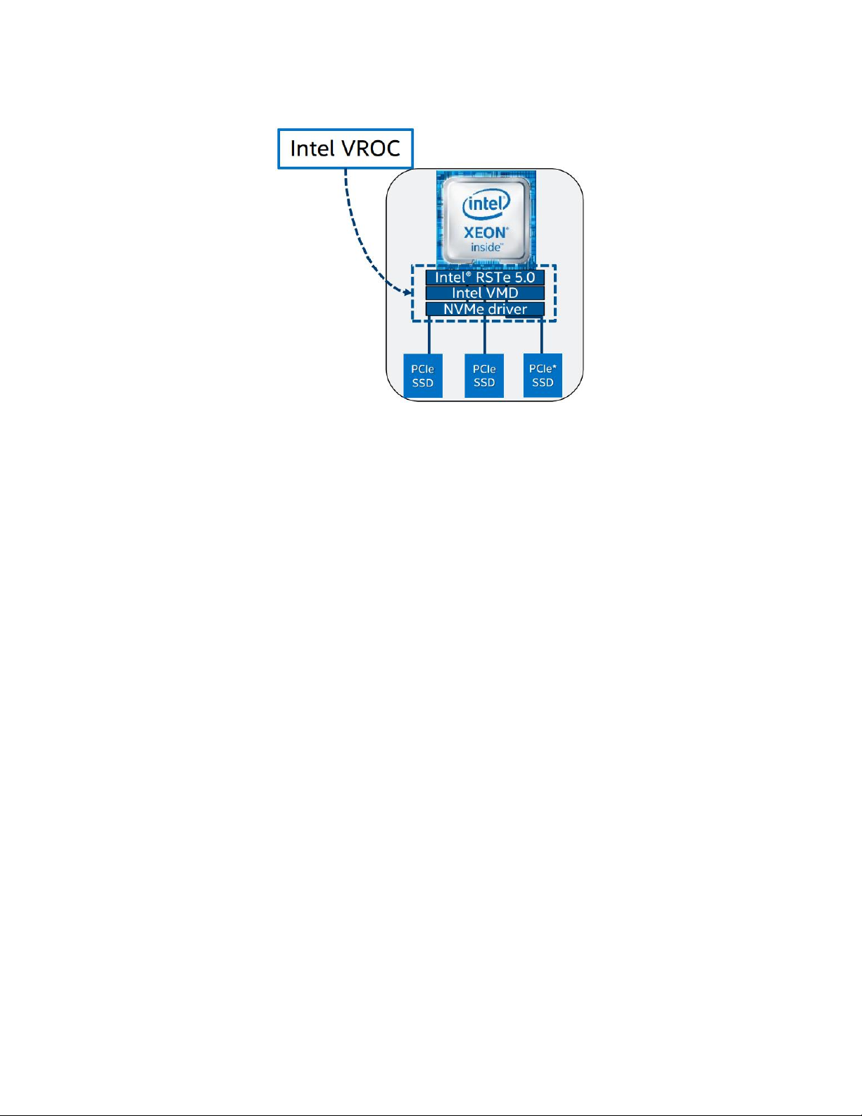
Intel® Server System R2000WF Product Family Technical Product Specification
7.4.3 Intel® Virtual RAID on Chip (Intel® VROC) for NVMe*
Intel® Virtual RAID on Chip (Intel® VROC) enables NVMe* boot on RAID and volume management (Intel® RSTe
5.0 + Intel® VMD)
Figure 69. Intel® VROC basic architecture overview
Intel® VROC supports the following:
I/O processor with controller (ROC) and DRAM.
No need for battery backup / RAID maintenance free backup unit.
Protected write back cache – software and hardware that allows recovery from a double fault.
Isolated storage devices from OS for error handling.
Protected R5 data from OS crash.
Boot from RAID volumes based on NVMe SSDs within a single Intel VMD domain.
NVMe SSD hot plug and surprise removal on CPU PCIe* lanes.
LED management for CPU PCIe attached storage.
RAID / storage management using representational state transfer (RESTful) application programming
interfaces (APIs).
Graphical user interface (GUI) for Linux*.
4K native NVMe SSD support.
Enabling Intel VROC support requires installation of an optional upgrade key on to the server board as
shown in Figure 70.
Table 63 identifies available Intel VROC upgrade key options.
96
Page 97

Intel® Server System R2000WF Product Family Technical Product Specification
NVMe* RAID Major Features
Standard Intel® VROC
(iPC VROCSTANMOD)
Premium Intel® VROC
(iPC VROCPREMMOD)
CPU attached NVMe SSD – high perf.
√
√
Boot on RAID volume
√
√
Third party vendor SSD support
√
√
Intel® RSTe 5.0 RAID 0/1/10
√
√
Intel® RSTe 5.0 RAID 5
-
√
RAID write hole closed (RMFBU replacement)
-
√
Hot plug/ surprise removal
(2.5” SSD form factor only
√
√
Enclosure LED management
√
√
Figure 70. Intel® VROC upgrade key
Table 63. Intel® VROC upgrade key options
Note: Intel® VROC Upgrade Keys referenced in
Table 63 are used for PCIe* NVMe* SSDs only. For SATA RAID support, see Section 7.2.
7.4.4 NVMe* Drive Population Rules for Intel® VROC
In order to support NVMe RAID and NVMe Management features, the optional Intel® VROC Key must be
installed on to the server board. With the Intel VROC key installed, specific drive population rules exist and
must be followed for proper support of the NVMe management features.
The backplane can support PCIe interfaces from the onboard OCuLink connectors on the server board,
and/or optional add-in Intel Tri-Mode RAID modules, PCIe Switch cards and Retimer cards. When cabling the
PCIe interfaces from two different PCIe interface sources to the backplane, the cables from each source must
be connected in defined drive sets of four (0,1,2,3) & (4,5,6,7) as shown in the following diagrams.
Note: The use of one or more OCuLink connectors on the server board to the backplane is considered a
single source.
97
Page 98

Intel® Server System R2000WF Product Family Technical Product Specification
PCIe Source #1
PCIe Source #2
PCIe Source #1
PCIe Source #2
Front Drive Connectors
Back OCuLink Cable Connectors
Figure 71. Backplane cabling from two PCIe sources
When cabling the backplane from two different PCIe sources, no other drive set combinations beyond those
defined above are supported.
Drive population rules will differ depending on the source of the PCIe interface to the backplane. In addition,
specific drive population limits exist when populating a backplane with both NVMe and SAS drive types.
The following sections define the drive population rules associated with each of the available PCIe sources to
the backplane.
NOTE: When connecting the backplane to two different PCIe sources, the defined population rules for each
PCIe source are applied to the drive set connected to it
7.4.4.1 Onboard PCIe OCuLink Connectors and / or Intel Tri-mode RAID module to 8 x 2.5” Combo
Backplane
The following information is applicable when PCIe signal to the 8x2.5” combo backplane are cabled from the
PCIe OCuLink connectors located on the server board and/or an optionally installed Intel® Tri-mode RAID
Module.
OCuLink connectors on the server board are considered a single PCIe source to the backplane, and
therefore can only be connected in defined drive sets 0-3 or 4-7
NVMe drive management sideband signals on the backplane are routed between drive connector pairs:
(0,1) (2,3) (4,5) and (6,7)
98
Page 99
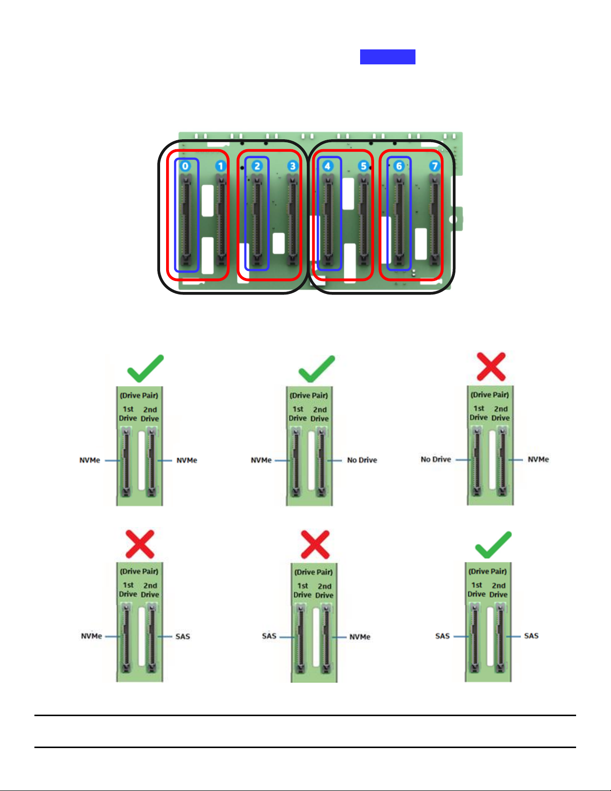
Intel® Server System R2000WF Product Family Technical Product Specification
PCIe Source Drive Set
PCIe Source Drive Set
In order to support NVMe drive management within a defined drive pair, an NVMe drive MUST be
populated in the first drive connector of the given pair (drives 0, 2, 4, or 6)
Combining an NVMe drive with a SAS/SATA drive within a defined drive pair is NOT supported.
Example) With an NVMe drive installed to drive connector 0, drive connector 1 cannot be populated with
a SAS/SATA drive. The same rule applies to ALL other drive pairs on the backplane.
The following illustrations identify supported and unsupported drive populations associated with any
defined drive pair of the 8x2.5” combo backplane when Intel VROC is used for NVMe drive management.
Where 1st Drive = drive connectors 0, 2, 4, or 6 and 2nd Drive = drive connectors 1, 3, 5, or 7
Note: The NVMe drive population rules defined above are only applicable when the Intel® VROC accessory
option is installed and used to provide NVMe drive management.
99
Page 100

Intel® Server System R2000WF Product Family Technical Product Specification
PCIe Source Drive Set
PCIe Source Drive Set
1st Drive = NVMe +
NVMe in any sequential
drive slot (No gaps)
Mixing of NVMe and SAS
within a common drive set
is not supported
= Supported
= Not Supported
7.4.4.2 4 port / 8 port PCIe* Switch to 8 x 2.5” Combo Backplane
The following information is applicable when PCIe signal to the 8x2.5” combo backplane are cabled from 4
or 8 port PCIe Switch add-in cards.
NVMe drive management sideband signals on the backplane are routed between drive connector sets:
(0,1,2,3) and (4,5,6,7)
In order to support NVMe drive management within a defined drive set, an NVMe drive MUST be
populated in the first drive connector of the given set (drive connectors 0 or 4). Additional NVMe drives
within the drive set must be populated in sequential order with no gaps between drive connectors.
Combining NVMe drives and SAS/SATA drives within a defined drive set is NOT supported.
The following illustrations identify supported and unsupported drive populations associated with any
defined drive set of the 8x2.5” combo backplane when an Intel® VROC key is installed to the server board
and the PCIe source to the backplane is from an add-in PCIe Switch card.
100
 Loading...