

Page 1

Intel® Server System
R1304BTSSFAN/R1304BTLSFAN/
R1304BTLSHBN Service Guide
A Guide for Technically Qualified Assemblers of Intel® Identified
Subassemblies/Products
Intel Order Number G21355-003
Page 2

Disclaimer
®
Information in this document is provided in connection with Intel
estoppel or otherwise, to any intellectual property rights is granted by this document. Except as provided in Intel
products. No license, express or implied, by
®
’s
Terms and Conditions of Sale for such products, Intel® assumes no liability whatsoever, and Intel® disclaims any
express or implied warranty, relating to sale and/or use of Intel® products including liability or warranties relating to
fitness for a particular purpose, merchantability, or infringement of any patent, copyright or other intellectual property
right. Intel
applications or for any other application in which the failure of the Intel® product could create a situation where
personal injury or death may occur. Intel
®
products are not designed, intended or authorized for use in any medical, life saving, or life sustaining
®
may make changes to specifications and product descriptions at any time,
without notice.
®
server boards contain a number of high-density VLSI and power delivery components that need adequate
Intel
airflow for cooling. Intel®’s own chassis are designed and tested to meet the intended thermal requirements of these
components when the fully integrated system is used together. It is the responsibility of the system integrator that
chooses not to use Intel developed server building blocks to consult vendor datasheets and operating parameters to
determine the amount of airflow required for their specific application and environmental conditions. Intel Corporation
can not be held responsible if components fail or the server board does not operate correctly when used outside any
of their published operating or non-operating limits.
Intel and Intel Xeon are trademarks or registered trademarks of Intel Corporation or its subsidiaries in the United
States and other countries.
* Other names and brands may be claimed as the property of others.
Copyright © 2011, Intel Corporation. All Rights Reserved
ii Intel® Server System R1304BTSSFAN/R1304BTLSFAN/R1304BTLSHBN Service Guide
Page 3

Safety Information
Important Safety Instructions
Read all caution and safety statements in this document before performing any of the
instructions. See also Intel Server Boards and Server Chassis Safety Information on the
®
Server Deployment Toolkit CD and/or at http://www.intel.com/support/
Intel
motherboards/server/sb/cs-010770.htm.
Wichtige Sicherheitshinweise
Lesen Sie zunächst sämtliche Warnund Sicherheitshinweise in diesem Dokument, bevor
Sie eine der Anweisungen ausführen. Beachten Sie hierzu auch die Sicherheitshinweise zu
Intel-Serverplatinen und Servergehäusen auf der Intel
oder unter
http://www.intel.com/support/motherboards/server/sb/cs-010770.htm.
®
Server Deployment Toolkit CD
Consignes de sécurité
Lisez attention toutes les consignes de sécurité et les mises en garde indiquées dans ce
document avant de suivre toute instruction. Consultez Intel Server Boards and Server
Chassis Safety Information sur le Intel
vous sur le site
http://www.intel.com/support/motherboards/server/sb/cs-010770.htm.
®
Server Deployment Toolkit CD ou bien rendez-
Instrucciones de seguridad importantes
Lea todas las declaraciones de seguridad y precaución de este documento antes de realizar
cualquiera de las instrucciones. Vea Intel Server Boards and Server Chassis Safety
Information en el Intel
support/motherboards/server/sb/cs-010770.htm.
®
Server Deployment Toolkit CD y/o en http://www.intel.com/
Intel® Server System R1304BTSSFAN/R1304BTLSFAN/R1304BTLSHBN Service Guide iii
Page 4
iv Intel® Server System R1304BTSSFAN/R1304BTLSFAN/R1304BTLSHBN Service Guide
Page 5

Warnings
Heed safety instructions: Before working with your server product, whether you are
using this guide or any other resource as a reference, pay close attention to the safety
instructions. You must adhere to the assembly instructions in this guide to ensure and
maintain compliance with existing product certifications and approvals. Use only the
described, regulated components specified in this guide. Use of other products/
components will void the UL listing and other regulatory approvals of the product and
will most likely result in noncompliance with product regulations in the region(s) in which
the product is sold.
System power on/off: The power button DOES NOT turn off the system AC power. To
remove power from system, you must unplug the AC power cord from the wall outlet.
Make sure the AC power cord is unplugged before you open the chassis, add, or remove
any components.
Hazardous conditions, devices and cables: Hazardous electrical conditions may be
present on power, telephone, and communication cables. Turn off the server and
disconnect the power cord, telecommunications systems, networks, and modems attached
to the server before opening it. Otherwise, personal injury or equipment damage can
result.
Electrostatic discharge (ESD) and ESD protection: ESD can damage disk drives,
boards, and other parts. We recommend that you perform all procedures in this chapter
only at an ESD workstation. If one is not available, provide some ESD protection by
wearing an antistatic wrist strap attached to chassis ground any unpainted metal surface on
your server when handling parts.
ESD and handling boards: Always handle boards carefully. They can be extremely
sensitive to ESD. Hold boards only by their edges. After removing a board from its
protective wrapper or from the server, place the board component side up on a grounded,
static free surface. Use a conductive foam pad if available but not the board wrapper. Do
not slide board over any surface.
Installing or removing jumpers: A jumper is a small plastic encased conductor that slips
over two jumper pins. Some jumpers have a small tab on top that you can grip with your
fingertips or with a pair of fine needle nosed pliers. If your jumpers do not have such a tab,
take care when using needle nosed pliers to remove or install a jumper; grip the narrow
sides of the jumper with the pliers, never the wide sides. Gripping the wide sides can
damage the contacts inside the jumper, causing intermittent problems with the function
controlled by that jumper. Take care to grip with, but not squeeze, the pliers or other tool
you use to remove a jumper, or you may bend or break the pins on the board.
Intel® Server System R1304BTSSFAN/R1304BTLSFAN/R1304BTLSHBN Service Guide v
Page 6

vi Intel® Server System R1304BTSSFAN/R1304BTLSFAN/R1304BTLSHBN Service Guide
Page 7

Preface
About this Manual
Thank you for purchasing and using the Intel® Server System R1304BTSSFAN/
R1304BTLSFAN/R1304BTLSHBN.
This manual is written for system technicians responsible for troubleshooting, upgrading,
and repairing this server system. This document provides reference information, feature
information, and step-by-step instructions on how to add and replace components on the
server system.
Manual Organization
Chapter 1 provides an overview of the server system. In this chapter, you will find a list of
the server system features, illustrations of the product, and product diagrams to help you
identify components and their locations.
Chapter 2 provides instructions on using the utilities shipped with the board or that may be
required to update the system. This includes how to navigate through the BIOS Setup
screens, perform a BIOS update, and reset the password or CMOS. Information about the
specific BIOS settings and screens is available in the Intel
Technical Product Specification.
Chapter 3 provides instructions on adding and replacing components. Use this chapte r for
step-by-step instructions and diagrams for installing or replacing components such as the
fans, power supply, drives, and other components.
At the back of this manual, you will find technical specifications, troubleshooting tips,
regulatory information, complete safety information, “getting help” information, and
the warranty.
®
Server Board S1200BT
Intel® Server System R1304BTSSFAN/R1304BTLSFAN/R1304BTLSHBN Service Guide vii
Page 8

Product Contents
The Intel® Server System R1304BTSSFAN ships with the Intel® Server Board
S1200BTS. The Intel
®
Server Board S1200BTL.
Intel
There are three versions of this server system: the Intel® Server System R1304BTSSF AN,
®
Server System R1304BTLSFAN and the Intel® Server System R1304BTLSHBN.
Intel
The contents of each server system are listed below.
®
Server System R1304BTLSFAN/R1304BTLSHBN ships with the
Intel® Server System R1304BTSSFAN Contents
Your Intel® Server System R1304BTSSFAN ships with the following items:
• One Intel
• One 250-W power supply module, installed in the server system
• Three system fans, with attached cables, installed in the server system
• One passive heat sink, in the server system product box
• Four hard disk drive brackets, installed in the server system
• One PCI-E X 8 low profile riser card with supporting bracket, installed in the
server system
• Rack handles, installed in the server system
• Standard front panel, installed in the server system
®
Server Board S1200BTS installed in the server system
• Cables:
— Four SATA cables for SATA HDDs
— One front panel USB cable, installed in the server system
— One front panel cable, installed in the server system
• Documentation, drivers, and installation CD
Intel® Server System R1304BTLSFAN Contents
Your Intel® Server System R1304BTLSFAN ships with the following items:
• One Intel
• One 250-W power supply module, installed in the server system
• Three system fans, with attached cables, installed in the server system
• One passive heat sink, in the server system product box
• Four hard disk drive brackets, installed in the server system
• One PCI-E x 8 low profile riser card with supporting bracket, installed in the
server system
®
Server Board S1200BTL installed in the server system
viii Intel® Server System R1304BTSSFAN/R1304BTLSFAN/R1304BTLSHBN Service Guide
Page 9

• Rack handles, installed in the server system
• Standard front panel, installed in the server system
• Cables:
— Four SATA cables for SATA HDDs
— One front panel USB cable, installed in the server system
— One front panel cable, installed in the server system
• Documentation, drivers, and installation CD
Intel® Server System R1304BTSSFAN/R1304BTLSFAN/R1304BTLSHBN Service Guide ix
Page 10

Intel® Server System R1304BTLSHBN Contents
Your Intel® Server System R1304BTLSHBN ships with the following items:
• One Intel
• One 350-W power supply module, installed in the server system
• Three system fans, with attached cables, installed in the server system:
• One passive heat sink, in the server system product box
• Four hot-swap hard disk drive carriers, installed in the server system.
• One PCI-E x 8 low profile riser card with supporting bracket, installed in the
server system.
• Rack handles, installed in the server system
• Standard front panel, installed in the server system
• Standard HDD backplane, installed in the server system.
• Cables:
®
Server Board S1200BTL installed in the server system
— Four SATA cables, installed in the server system
— One front panel USB cable, installed in the server system
— One front panel cable, installed in the server system
— One SPGIO cable, installed in the server system
— One I2C cable, installed in the server system
• Documentation, drivers, and installation CD
x Intel® Server System R1304BTSSFAN/R1304BTLSFAN/R1304BTLSHBN Service Guide
Page 11
Server System References
If you need more information about this product or information about the accessories that
you can use with this server chassis, use the following resources.
For this Information or
Software
Technical information
about the server chassis,
including sub-system
overviews and
mechanical drawings
If you just received this
produ
ct and need to
install it
Accessories or other Intel
rver products
se
Hardware (peripheral
board
s, adapter cards)
and operating systems
that have been tested with
this product
Processors that have
tested with this
been
product
DIMMs that have been
tested with this product
Use this Document or
®
Intel
Server System R1304BTSSFAN/R1304BTLSFAN/
R1304BTLSHBN Technical Product Specification
®
Intel
Server System S1200BT Technical Product Specification
http://www.intel.com/support/motherboards/server/
Intel® Server System R1304BTLSFAN/R1304BTLSHBN Quick
Start User's Guide in the product box.
Spares/Parts List & Configuration Guide
This is available from your Intel field represe
Configurator Tool at:
http://serverconfigurator.intel.com/default.aspx
For the Tested Hardware Operating Systems List, y
®
Intel
Server Configurator Tool:
http://serverconfigurator.intel.com/default.aspx
Supported processors can be found at:
http://www.intel.com/suppor
Supported memory can be found at:
http://www.intel.com/suppor
t/motherboards/server/
t/motherboards/server/
Software
ntative or on the Server
ou can go to the
To make sure your system
f
alls within the allowed
power budget
For software to manage
y
our Intel
For drivers Driver (for an extensive list of drivers available)
For firmware and BIOS
upda
For diagnostics test
so
Intel® Server System R1304BTSSFAN/R1304BTLSFAN/R1304BTLSHBN Service Guide xi
tes
ftware
®
server
Power Budget Tool
http://www.intel.com/suppor
®
System Management
Intel
http://www.intel.com/suppor
Operating System Driver (for operating system drivers)
http://www.intel.com/support/motherboards/server/
Firmware can be found at:
http://www.intel.com/suppor
Diagnostics
http://www.intel.com/suppor
t/motherboards/server/
t/motherboards/server/
t/motherboards/server/
t/motherboards/server/
Page 12

xii Intel® Server System R1304BTSSFAN/R1304BTLSFAN/R1304BTLSHBN Service Guide
Page 13

Table of Contents
Safety Information ..................................................................................................... iii
Important Safety Instructions ................................................................................................ iii
Wichtige Sicherheitshinweise ............................................................................................... iii
Consignes de sécurité .......................................................................................................... iii
Instrucciones de seguridad importantes ............................................................................... iii
Warnings ................................................................................................................................ v
Preface .......................................................................................................................vii
About this Manual ................................................................................................................ vii
Manual Organization ............................................................................................................vii
Product Contents .................................................................................................................viii
Server System References ................................................................................................... xi
®
Intel
Server System R1304BTSSFAN Contents .......................................................viii
®
Server System R1304BTLSFAN Contents ........................................................viii
Intel
®
Intel
Server System R1304BTLSHBN Contents .........................................................x
Chapter 1: Server System Features .......................................................................... 1
Chassis Component Identification .........................................................................................4
System Front Panel .......................................................................................................4
System Rear .................................................................................................................. 6
Peripheral Devices (R1304BTSSFAN/R1304BTLSFAN) .............................................. 7
Peripheral Devices (R1304BTLSHBN) ..........................................................................7
Hard Disk Drives ............................................................................................................7
Slimline Optical Drive Carrier ........................................................................................7
Internal Components (R1304BTSSFAN) .......................................................................8
Internal Components (R1304BTLSFAN) .......................................................................9
Internal Components (R1304BTLSHBN) .....................................................................10
Server Board Connectors/Components (S1200BTS) ..........................................................11
Server Board Connectors/Components (S1200BTL) ..........................................................12
Configuration Jumpers .........................................................................................................14
Hardware Requirements ......................................................................................................16
Processor ....................................................................................................................16
Memory ........................................................................................................................16
Chapter 2: Server Utilities ........................................................................................19
Using the BIOS Setup Utility ................................................................................................19
Starting Setup ..............................................................................................................19
If You Cannot Access Setup ........................................................................................19
Setup Menus ...............................................................................................................19
Upgrading the BIOS .............................................................................................................21
Intel® Server System R1304BTSSFAN/R1304BTLSFAN/R1304BTLSHBN Service Guide xiii
Page 14

Preparing for the Upgrade ........................................................................................... 21
Upgrading the BIOS .................................................................................................... 22
Recovering the BIOS .................................................................................................. 22
Recovering the BIOS ........................................................................................................... 22
Clearing the Password ........................................................................................................ 23
Clearing the CMOS ..................................................................................................... 24
Updating the Integrated BMC ...................................................................................... 24
Updating ME Firmware ............................................................................................... 25
Chapter 3: Hardware Installations and Upgrades ..................................................27
Before You Begin ................................................................................................................ 27
Tools and Supplies Needed ........................................................................................ 27
System References ..................................................................................................... 27
Removing and Installing the Server Cover .......................................................................... 28
Removing the Server System Cover ........................................................................... 28
Installing the Server System Cover ............................................................................. 29
Removing and Installing the Processor Air Duct ................................................................. 30
Removing the Processor Air Duct ............................................................................... 30
Installing the Processor Air Duct ................................................................................. 31
Installing and Removing Memory ........................................................................................ 32
Installing DIMMs .......................................................................................................... 33
Removing DIMMs ........................................................................................................ 33
Replacing the Processor ..................................................................................................... 35
Removing the Heat Sink and Processor ..................................................................... 35
Installing the Processor ............................................................................................... 36
Installing the Heat Sink ............................................................................................... 39
Installing and Removing a Hard Drive (R1304BTSSFAN/R1304BTLSFAN) ...................... 41
Installing a Hard Disk Drive (R1304BTSSFAN/R1304BTLSFAN) .............................. 41
Removing a Hard Disk Drive (R1304BTSSFAN/R1304BTLSFAN) ............................ 43
Installing and Removing a Hot-Swap SATA Drive (R1304BTLSHBN) ................................ 44
Installing a Hot-Swap SATA Drive (R1304BTLSHBN) ................................................ 44
Removing a Hot-Swap SATA Drive (R1304BTLSHBN) .............................................. 46
Installing or Removing a Slimline Optical Drive ................................................................... 48
Installing a Slimline Optical Drive ................................................................................ 48
Removing a Slimline Optical Drive .............................................................................. 50
Installing and Removing the PCIe* Riser Assembly ............................................................ 51
Removing the PCIe* Riser Assembly .......................................................................... 51
Installing the PCIe* Riser Assembly ............................................................................ 52
Installing or Replacing a PCIe* Riser Card ......................................................................... 53
Removing a PCIe* Riser Card .................................................................................... 53
Installing a PCIe* Riser Card ...................................................................................... 54
Installing and Removing a PCI Add-in Card ........................................................................ 55
Installing a PCI Add-in Card ........................................................................................ 55
Removing a PCI Add-in Card ...................................................................................... 56
xiv Intel® Server System R1304BTSSFAN/R1304BTLSFAN/R1304BTLSHBN Service Guide
Page 15

Replacing the Server Board .................................................................................................58
Removing the Server Board ........................................................................................58
Installing the Server Board ..........................................................................................59
Replacing the CMOS Battery ...............................................................................................61
Replacing the Power Supply ................................................................................................63
Replacing a System Fan ......................................................................................................64
Replacing the System Fans .........................................................................................64
Installing and Removing the Rack Handles ......................................................................... 66
Installing the Rack Handles .........................................................................................66
Removing the Rack Handles .......................................................................................67
Appendix A: Technical Reference .......................................................................... 69
Cable Routing ......................................................................................................................69
Cable Routing (R1304BTSSFAN) ...............................................................................70
Cable Routing (R1304BTLSFAN) ................................................................................71
Cable Routing (R1304BTLSHBN) ...............................................................................72
350-W Single Power Supply Input Voltages ........................................................................ 73
350-W Single Power Supply Output Voltages .....................................................................73
System Environmental Specifications ..................................................................................74
Appendix B: Troubleshooting .................................................................................75
Resetting the System ...........................................................................................................75
Problems following Initial System Installation ...................................................................... 76
First Steps Checklist ....................................................................................................76
Hardware Diagnostic Testing ...............................................................................................77
Verifying Proper Operation of Key System Lights .......................................................77
Confirming Loading of the Operating System ..............................................................77
Specific Problems and Corrective Actions ...........................................................................77
Power Light Does Not Light .........................................................................................78
No Characters Appear on Screen ...............................................................................78
Characters Are Distorted or Incorrect ..........................................................................79
System Cooling Fans Do Not Rotate Properly ............................................................79
Drive Activity Light Does Not Light ..............................................................................80
CD-ROM Drive or DVD-ROM Drive Activity Light Does
Not Light ..........................................................................................................80
Cannot Connect to a Server ........................................................................................80
Problems with Network ................................................................................................81
System Boots when Installing PCI Card ...................................................................... 82
Problems with Newly Installed Application Software ................................................... 82
Problems with Application Software that Ran
Correctly Earlier ...............................................................................................82
Devices are not Recognized under Device Manager (Microsoft Windows* Operating Sys-
tem) ..................................................................................................................83
Hard Drive(s) are not Recognized ...............................................................................83
Bootable CD-ROM Disk Is Not Detected .....................................................................83
Intel® Server System R1304BTSSFAN/R1304BTLSFAN/R1304BTLSHBN Service Guide xv
Page 16

LED Information .......................................................................................................... 84
BIOS POST Beep Codes ............................................................................................ 84
Appendix C: Warranty ..............................................................................................85
Limited Warranty for Intel® Chassis Subassembly Products ............................................... 85
Appendix D: Getting Help ........................................................................................89
World Wide Web .................................................................................................................89
Telephone ........................................................................................................................... 89
xvi Intel® Server System R1304BTSSFAN/R1304BTLSFAN/R1304BTLSHBN Service Guide
Page 17

List of Figures
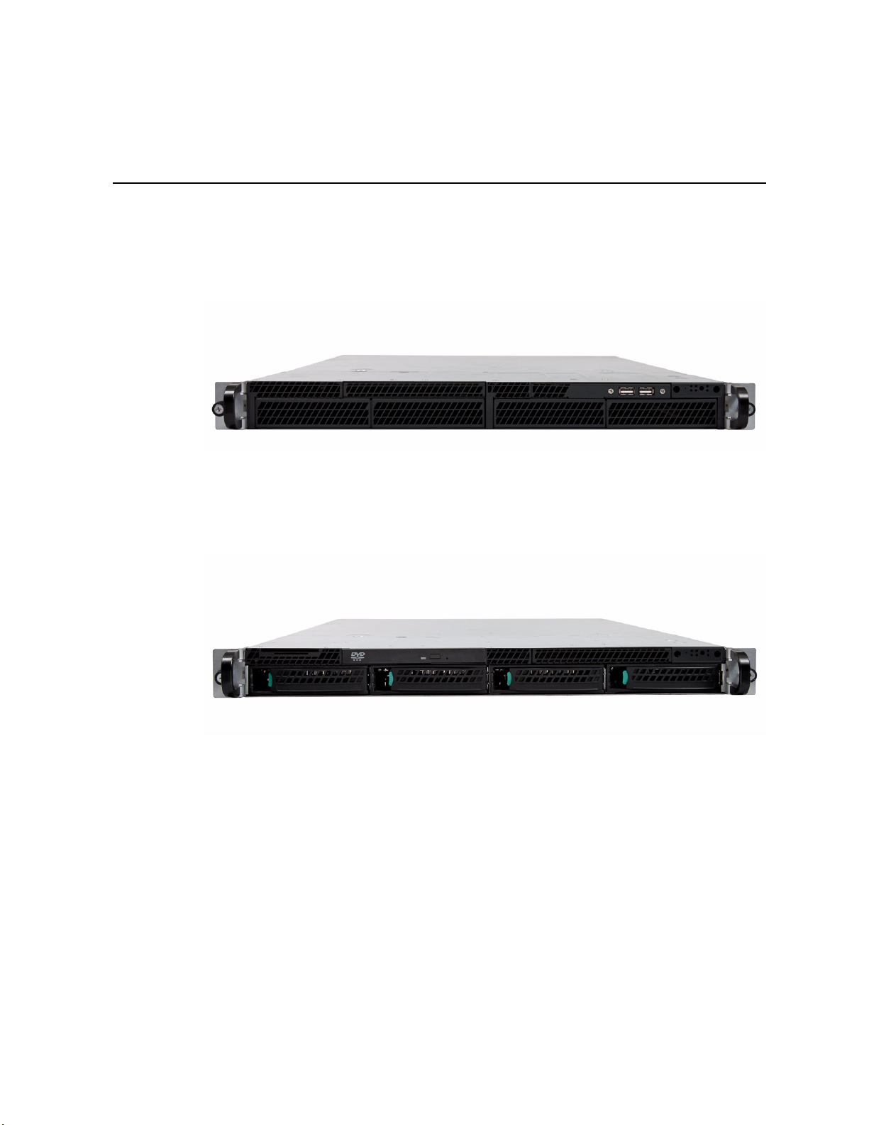
Figure 1. Intel® Server System R1304BTSSFAN/R1304BTLSFAN.......................................... 1
Figure 2. Intel
Figure 3. Front Controls and LEDs............................................................................................ 4
Figure 4. Back Panel Connectors.............................................................................................. 6
Figure 5. System Components (R1304BTSSFAN) ................................................................... 8
Figure 6. System Components (R1304BTLSFAN).................................................................... 9
Figure 7. System Components (R1304BTLSHBN) ................................................................. 10
Figure 8. Intel
Figure 9. Intel
Figure 10. Configuration Jumper Locations (S1200BTS)........................................................ 14
Figure 11. Configuration Jumper Locations ............................................................................ 14
Figure 12. Removing the Server System Cover...................................................................... 28
Figure 13. Installing the Server System Cover........................................................................ 29
Figure 14. Installing the Processor Air Duct............................................................................ 31
Figure 15. Installing the Memory............................................................................................. 33
Figure 16. Lifting the Processor Socket Handle...................................................................... 36
Figure 17. Opening the Load Plate ......................................................................................... 37
Figure 18. Removing the Shipping Cover ............................................................................... 37
Figure 19. Installing the Processor.......................................................................................... 38
Figure 20. Removing the Protective Socket Cover ................................................................. 38
Figure 21. Installing the Heat Sink .......................................................................................... 39
Figure 22. Removing Drive Carrier from the Server System (R1304BTLSFAN)..................... 42
Figure 23. Installing Drive into Drive Carrier (R1304BTSSFAN/R1304BTLSFAN)................. 42
Figure 24. Removing the Drive Carrier (R1304BTLSHBN)..................................................... 44
Figure 25. Installing Drive into Drive Carrier (R1304BTLSHBN)............................................. 45
Figure 26. Install Drive Assembly into the Server System (R1304BTLSHBN)........................ 46
Figure 27. Removing the Knock-out from the Sheet Metal Panel ........................................... 48
Figure 28. Attaching the latch to the Optical Drive.................................................................. 49
Figure 29. Installing the Optical Drive into the System............................................................ 49
Figure 30. Removing PCIe* Riser Assembly from the Server System.................................... 51
Figure 31. Installing PCIe* Riser Assembly into the Server System ....................................... 52
Figure 32. Removing Riser Card from Riser Assembly........................................................... 53
Figure 33. Installing Riser Card onto Riser Assembly............................................................. 54
Figure 34. Installing an Add-In Card........................................................................................ 56
Figure 35. Removing the Server Board................................................................................... 58
Figure 36. Installing the Server Board..................................................................................... 60
Figure 37. Replacing the CMOS Battery................................................................................. 62
Figure 38. Removing Power Supply........................................................................................ 63
Figure 39. Removing Bracket and System Fans from Server System.................................... 64
Figure 40. Installing the Rack Handle ..................................................................................... 66
Figure 41. Cable Routing (R1304BTLSFAN) .......................................................................... 70
Figure 42. Cable Routing (R1304BTLSFAN) .......................................................................... 71
®
Server System R1304BTLSHBN ..................................................................... 1
®
Server Board S1200BTS Layout.................................................................... 12
®
Server Board S1200BTL Layout .................................................................... 13
Intel® Server System R1304BTSSFAN/R1304BTLSFAN/R1304BTLSHBN Service Guide xvii
Page 18

Figure 43. Cable Routing (R1304BTLSHBN) ......................................................................... 72
xviii Intel® Server System R1304BTSSFAN/R1304BTLSFAN/R1304BTLSHBN Service Guide
Page 19

List of Tables
Table 1. Intel® Server System R1304BTSSFAN/R1304BTLSFAN/R1304BTLSHBN Feature
Summary ................................................................................................................................... 2
Table 2. Control Panel LED Functions ......................................................................................4
Table 3. NIC LED Descriptions .................................................................................................6
Table 4. Memory Configuration Table .....................................................................................16
Table 5. Setup Menu Key Use ................................................................................................20
Table 6. Power Supply Output Capability ................................................................................73
Table 7. System Environmental Specifications .......................................................................74
Table 8. Resetting the System ................................................................................................75
Table 9. LED Information ........................................................................................................84
Table 10. POST Error Beep Codes .........................................................................................84
Intel® Server System R1304BTSSFAN/R1304BTLSFAN/R1304BTLSHBN Service Guide xix
Page 20

xx Intel® Server System R1304BTSSFAN/R1304BTLSFAN/R1304BTLSHBN Service Guide
Page 21
1 Server System Features
This chapter briefly describes the main features of the server system. This chapter
provides illustrations of the product, a list of the server system features, and diagrams
showing the location of important components and connections on the server system.
Figure 1. Intel® Server System R1304BTSSFAN/R1304BTLSFAN
Note: Figure 1 is shown without an optional
Figure 2. Intel® Server System R1304BTLSHBN
Note: Figure 2 is shown with an optional optical drive installed.
optical drive installed.
Intel® Server System R1304BTSSFAN/R1304BTLSFAN/R1304BTLSHBN Service Guide 1
Page 22
Table 1 summarizes the features of the server system.
Table 1. Intel® Server System R1304BTSSFAN/R1304BTLSFAN/
R1304BTLSHBN Feature Summary
Feature Description
Dimensions • 1.67 inches high (4.24 centimeters)
• 17.25 inches wide (43.82 centimeters)
• 20 inches deep (50.80 centimeters)
• 33 pounds (15 kilograms)
Server Board Intel® Server System R1304BTSSFAN
®
• Intel
Intel® Server System R1304BTLSFAN/R1304BTLSHBN
• Intel
Processor Support for one Xeon® E3-1200 Series Processor or Intel® Core™
Processor i3-2100 Series in FC-LGA 1155 socket package.
Server Board S1200BTS
®
Server Board S1200BTL
• 2.5 GT/s point-to-point DMI interface to PCH
• LGA 1155 pin socket
• Max TDP 95W
Memory Two memory channels with support for 1066/1333 ECC Unbuffered
(UDIMM).
• Up to 2 UDIMMs per channel
• 32 GB max with x8 ECC UDIMM (2 Gb DRAM)
Chipset Intel® Server Board S1200BTS
• Support for Intel
Intel® Server Board S1200BTL
• Support for Intel
®
C202 Platform Controller Hub (PCH)
®
C204 Platform Controller Hub (PCH)
• ServerEngines* LLC Pilot III BMC controller (Integrated BMC)
Peripherals Slimline bay for slimline SATA optical drive.
One PCI Express* x8 add-in card slot (Gen 2).
I/O Control External connections:
• DB-15 video connectors
• DB-9 serial Port A connector
• Four USB 2.0 connectors
• Two USB 2.0 connectors (front)
Expansion Capabilities
(optional accessory
required)
Fans Supports three system fans.
One low-profile riser slot supporting one low-profile half-length PCI
Express* 2.0 x8 add-in card.
2 Intel® Server System R1304BTSSFAN/R1304BTLSFAN/R1304BTLSHBN Service Guide
Page 23
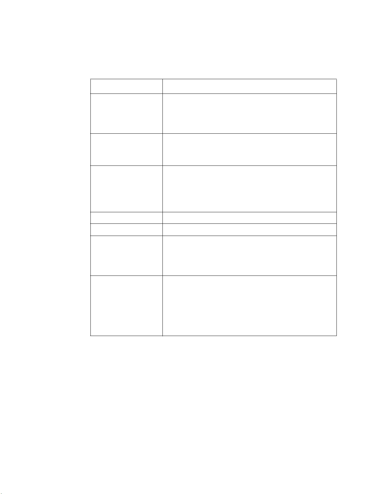
Table 1. Intel® Server System R1304BTSSFAN/R1304BTLSFAN/
R1304BTLSHBN Feature Summary
Feature Description
Video Intel® Server Board S1200BTS
• Silicon Motion SM712GX04LF02-BA
Intel® Server Board S1200BTL
• Onboard ServerEngines* LLC Pilot III BMC Controller
LAN • One Gigabit Ethernet device 82574L connect to PCI-E x1
interfaces on the PCH
• One Gigabit Ethernet PHY 82579 connected to PCH through
PCI-E x1 interface
Hard Drives Intel® Server System R1304BTSSFAN/R1304BTLSFAN:
• Four Fixed SATA drives
®
Server System R1304BTLSHBN:
Intel
• Four Hot-Swappable SATA/SAS drives (SAS drives are
supported when a SAS add-on card is installed)
Peripherals Slimline bay for SATA optical drive (optional).
Front panel Standard front panel
Power Supply Intel® Server System R1304BTSSFAN/R1304BTLSFAN:
• Single 250-W power supply
Intel® Server System R1304BTLSHBN:
• Single 350-W power supply
System Management Intel® Server System R1304BTLSFAN/R1304BTLSHBN:
Onboard LLC Pilot III Controller (Integrated BMC)
• Integrated Baseboard Management Controller (Integrated
BMC), IPMI 2.0 compliant
• Integrated 2D video controller on PCI-E x 1
• Optional Intel
and optional dedicated NIC module
®
Remote Management Module 4 (RMM4) lite
Intel® Server System R1304BTSSFAN/R1304BTLSFAN/R1304BTLSHBN Service Guide 3
Page 24
ABCDEFG
J
IH
AF003708
Chassis Component Identification
This section helps you identify the components of your server system. If you are near the
system, you can also use the Quick Reference Label on the inside of the chassis cover to
assist in identifying components.
System Front Panel
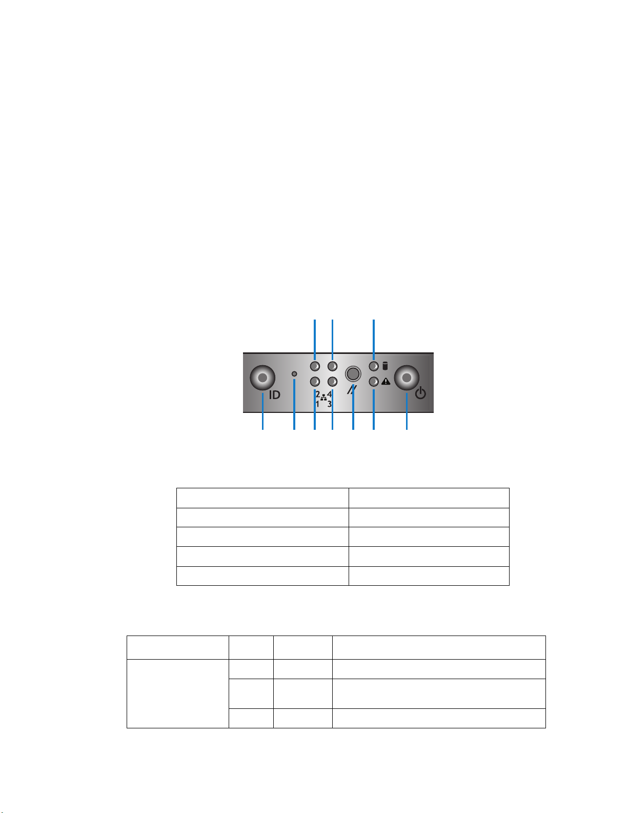
The front of the server system includes the following buttons and LEDs.
Note: The LAN3/4 LEDs are not used on the Intel® Server Systems R1304BTSSFAN/
R1304BTLSFAN or R1304BTLSHBN. Unstuffable ID Button with ID LED and Status/
Fault LED is not used on Intel
®
Server System R1304BTSSFAN.
A. Unstuffable ID Button with ID LED F. Status/Fault LED
B. NMI Button G. Power Button with power LED
C. LAN1 LED H. LAN2 LED
D. LAN3 LED I. LAN4 LED
E. Reset Button J. HDD LED
4 Intel® Server System R1304BTSSFAN/R1304BTLSFAN/R1304BTLSHBN Service Guide
Power/Sleep Green On Power on or S0 sleep.
LED Color Condition What It Means
Figure 3. Front Controls and LEDs
Table 2. Control Panel LED Functions
Green Blink S1 sleep or S3 standby only for workstation
baseboards.
Off Off (also sleep S4/S5 modes).
Page 25
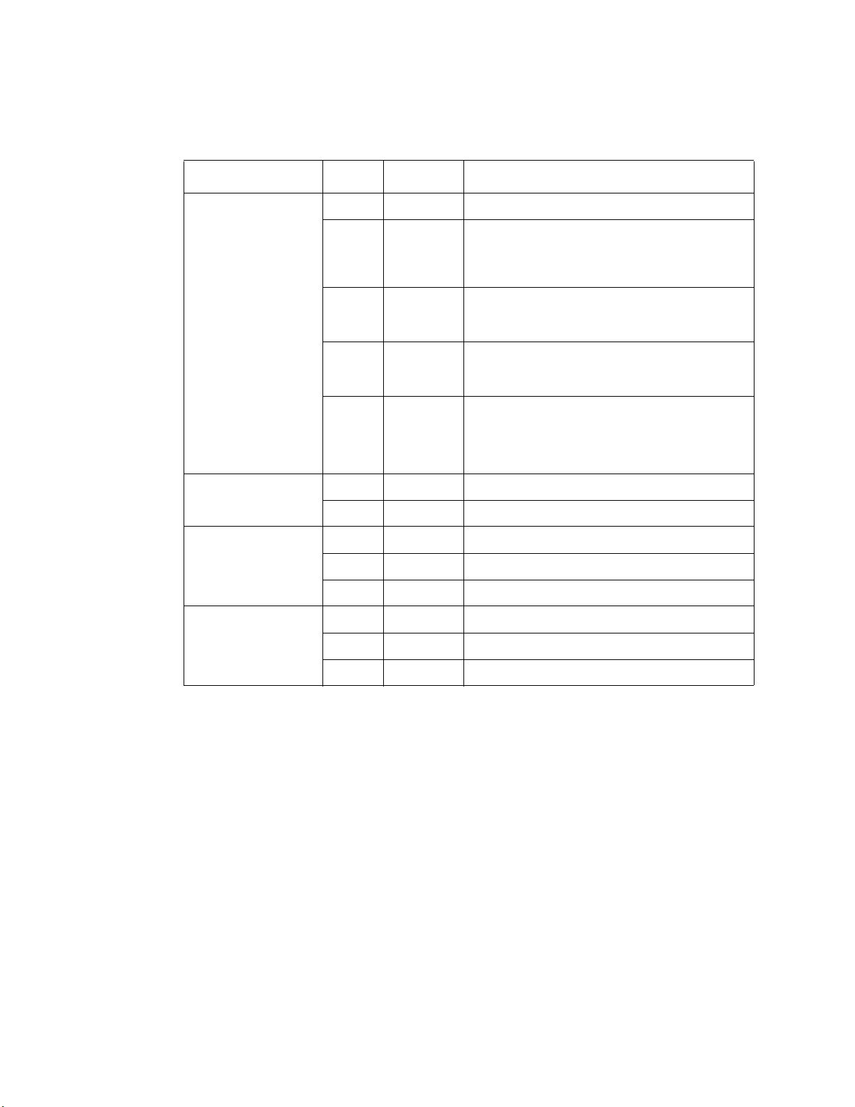
Table 2. Control Panel LED Functions
LED Color Condition What It Means
Status Green On System ready/No alarm.
Green Blink System ready, but degraded: redundancy lost
Amber On Critical alarm: Voltage, thermal, or power fault;
Amber Blink Non-Critical failure: Critical temp/voltage
Off AC power off: System unplugged.
Global HDD Activity Green Blink HDD access.
Off No access and no fault.
LAN 1-4 Activity/Link
(LAN 1-2 for Intel
Server Board
S1200BT)
Chassis Identification Blue On Front panel chassis ID button pressed.
®
Green On LAN link/no access.
Green Blink LAN access.
Off Idle.
such as PS or fan failure; non-critical temp/
voltage threshold; battery failure; or predictive PS
failure.
CPU missing; insufficient power unit redundancy
resource offset asserted.
threshold; VDR hot asserted; min number fans
not present or failed.
AC power on: System powered off and in
standby, no prior degraded\non-critical\critical
state.
Blue Blink Unit selected for identification via software.
Off No identification.
Intel® Server System R1304BTSSFAN/R1304BTLSFAN/R1304BTLSHBN Service Guide 5
Page 26
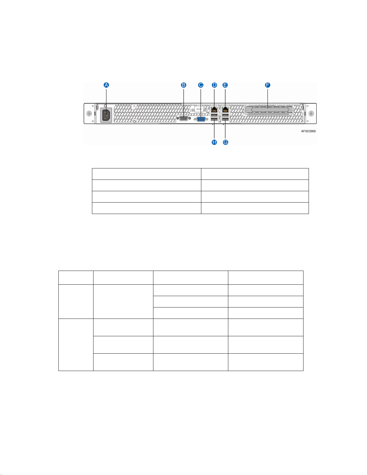
System Rear
A. AC Power Connector E. NIC 2 Connector (10/100/1000 MB)
B
C. Video Connector G. USB Ports
. Serial Port A F. PCI Express* Slot
D. NIC 1 Connector (10/100/1000 MB) H. USB Ports
Figure 4. Back Panel Connectors
The NIC LEDs at the right and left of each NIC provide the
following information.
Table 3. NIC LED Descriptions
LED LED State LED State NIC State
Left Green Off LAN link is not established.
On LAN link is established.
Blinking LAN activity is occurring.
Right N/A Off 10 Mbit/sec data rate is
Green On 100 Mbit/sec data is
Ye l l o w On 1000 Mbit/sec data rate is
selected
selected
selected
6 Intel® Server System R1304BTSSFAN/R1304BTLSFAN/R1304BTLSHBN Service Guide
Page 27

Peripheral Devices (R1304BTSSFAN/R1304BTLSFAN)
The server system provides locations and hardware for installing hard drives, slimline
CD-ROM drive, or DVD-ROM drive. You must purchase the drives separately. Available
options include:
• Slimline Optical Drive Bay
• Hard Disk Drive Bay HDD0/HDD1/HDD2/HDD3
Peripheral Devices (R1304BTLSHBN)
The server system provides locations and hardware for installing hard drives, slimline
CD-ROM drive, or DVD-ROM drive. You must purchase the drives separately. Available
options include:
• Slimline Optical Drive Bay
• Four Hard Disk Drive Bays
Hard Disk Drives
The Intel® Server System R1304BTSSFAN/R1304BTLSFAN/R1304BTLSHBN provides
six SATA ports.
For instructions on installing hard drives, see “Installing and Removing a Hard Drive
(R1304BTSSFAN/R1304BTLSFAN)” on page 41 on Page 41.
Note: Each drive can consume up to 17 W of power. Drives must be specified to run at a
maximum ambient temperature of 45
Note: The Intel® Server System R1304BTSSFAN/R1304BTLSFAN/R1304BTLSHBN does not
support all Serial ATA (SATA) hard drives. See
Page x for an Internet link to a list of supported hardware.
Slimline Optical Drive Carrier
One slimline drive carrier is included with your server system; you must purchase the
optical drive separately. To use the slimline DVD drive provided by Intel, use order code
AXXSATADVDROM. To use the slimline DVD CDRW drive provided by Intel, use
order code AXXSATADVDRWROM.
Note: The Intel® Server System R1304BTSSFAN/R1304BTLSFAN/R1304BTLSHBN does not
support all slimline optical drives. See
Internet link to a list of supported hardware. Intel provides accessory kits for these drives.
°C.
“Server System References” on page xi on
“Server System References” on page xi for an
For installation instructions for an optical drive, see “Removing a Slimline Optical Drive”
on page 50.
Intel® Server System R1304BTSSFAN/R1304BTLSFAN/R1304BTLSHBN Service Guide 7
Page 28
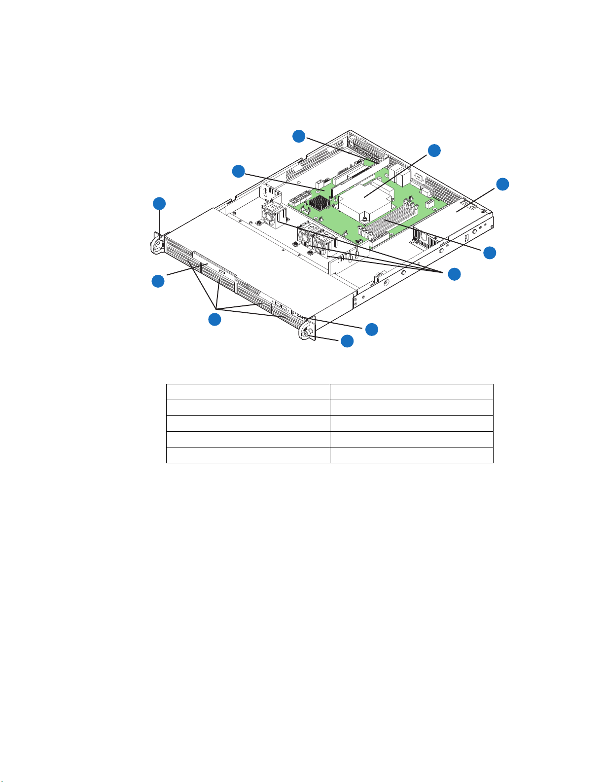
Internal Components (R1304BTSSFAN)
C
B
A
D
E
F
J
I
H
A
A. Rack Handles (two) F. System Memory DIMM Sockets
B. Server Board G. Cooling Fans
C. PCIe* Riser Assembly H. Front Panel
D. Processor and Heatsink I. Hard Drive Bays
E. Power Supply J. Front Panel Slimline Optical Drive
Figure 5. System Components (R1304BTSSFAN)
G
AF003908
8 Intel® Server System R1304BTSSFAN/R1304BTLSFAN/R1304BTLSHBN Service Guide
Page 29
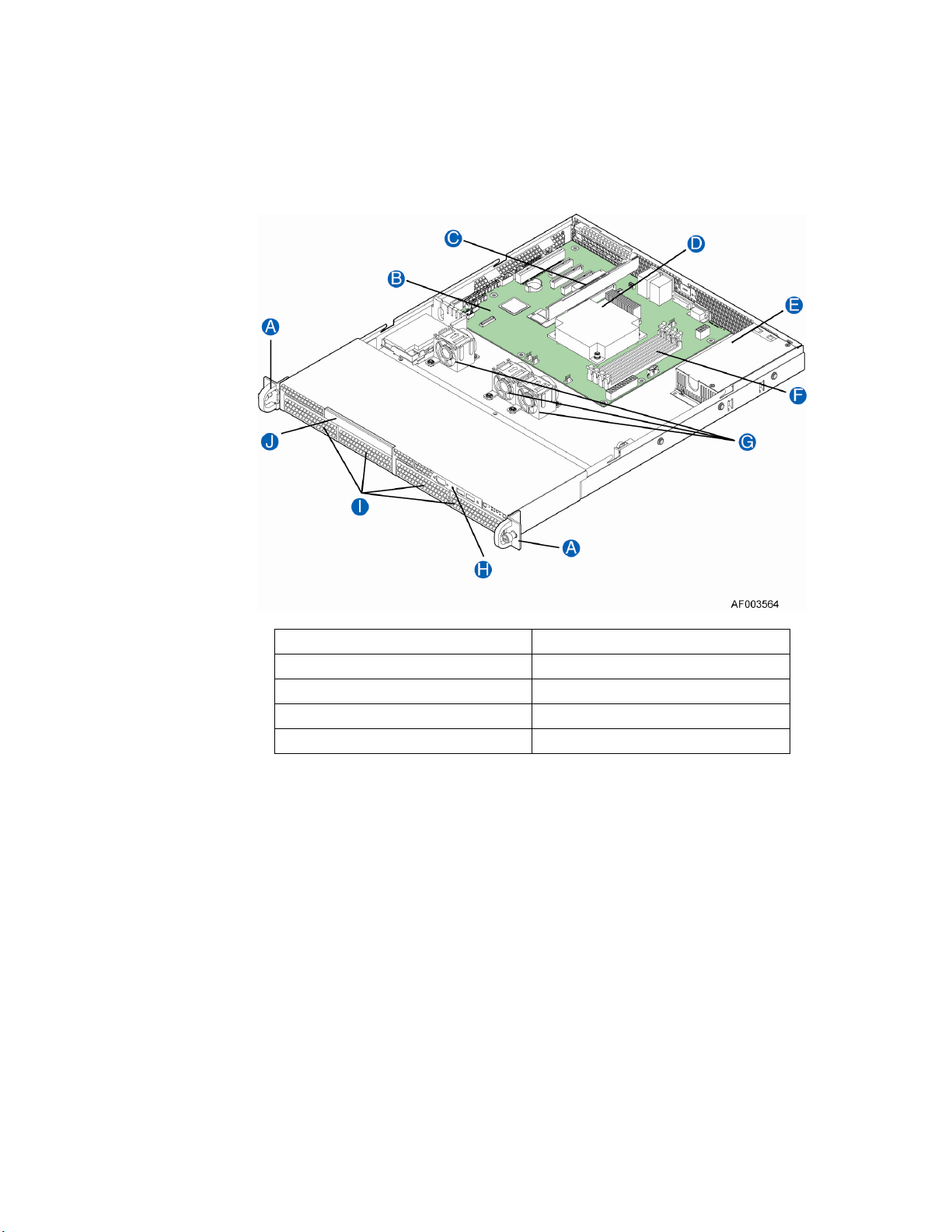
Internal Components (R1304BTLSFAN)
A. Rack Handles (two) F. System Memory DIMM Sockets
B. Server Board G. Cooling Fans
C. PCIe* Riser Assembly H. Front Panel
D. Processor and Heatsink I. Hard Drive Bays
E. Power Supply J. Front Panel Slimline Optical Drive
Figure 6. System Components (R1304BTLSFAN)
Intel® Server System R1304BTSSFAN/R1304BTLSFAN/R1304BTLSHBN Service Guide 9
Page 30
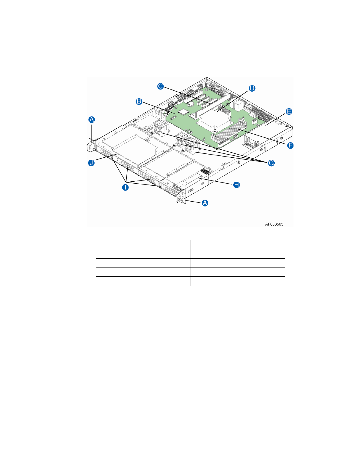
Internal Components (R1304BTLSHBN)
A. Rack Handles (two) F. System Memory DIMM Slots
B. Server Board G. Cooling Fans
C. PCIe* Riser Assembly H. Front Panel Board
D. Processor and Heatsink I. Hard Drive Bays
E. Power Supply J. Slimline Optical Drive
Figure 7. System Components (R1304BTLSHBN)
10 Intel® Server System R1304BTSSFAN/R1304BTLSFAN/R1304BTLSHBN Service Guide
Page 31

Server Board Connectors/Components (S1200BTS)
A. Slot 4, 32 Mbit/33 MHz PCI N. SYS_FAN_1
B. Slot 5/6, PCI Express* Gen2 x4 (x8
connector)
C. SATA_KEY P. CPU Fan connector
D. Slot 7, PCI Express* Gen2 x8 (x16
connector)
E. Ethernet and Dual USB COMBO R. SATA_SGPIO
F. Ethernet and Dual USB COMBO S. SYS_FAN_3
G. Video port T. Six 3Gb/s SATA ports
H. External Serial port U. Internal USB connector
I. CPU Power connector V. Internal USB
Intel® Server System R1304BTSSFAN/R1304BTLSFAN/R1304BTLSHBN Service Guide 11
O. CPU connector
Q. Chassis Intrusion
Page 32

J. SYS_FAN_2 W. CMOS battery
K. DIMM slots X. Front Panel
L. MAIN power connector Y. HDD LED
M. TPM connector
Figure 8. Intel® Server Board S1200BTS Layout
Server Board Connectors/Components (S1200BTL)
A Slot 1, 32 Mbit/33 MHz PCI R System FAN2 and System FAN3
Connector
B TPM S CPU connector
12 Intel® Server System R1304BTSSFAN/R1304BTLSFAN/R1304BTLSHBN Service Guide
Page 33

C Slot 3/4, PCI Express* Gen2 x4 (x8
connector)
D Slot 5, PCI Express* Gen2 x4 (x8
connector)
E Slot 6, PCI Express* Gen2 x8 (x16
connector)
F Chassis Intrusion W IPMB
G SATA_KEY X SYS_FAN_1
H Two Ethernet and Dual USB COMBO Y HSBP
I Video port Z SATA_SGPIO
J External Serial port AA Internal Serial Connector
K RMM4 Lite Connector BB Front Panel Connector
L CPU Power Connector CC HDD LED
M SYS_FAN_4 DD Internal USB Connector
N RMM4 Dedicated NIC connector EE CMOS battery
O Four DIMM Slots FF Four 3Gb/s SATA ports
P P/S AUX GG Two 6Gb/s SATA ports
T CPU Fan connector
U USB connector for smart module
V SAS Module connector
Q MAIN POWER HH Smart module
Figure 9. Intel® Server Board S1200BTL Layout
Intel® Server System R1304BTSSFAN/R1304BTLSFAN/R1304BTLSHBN Service Guide 13
Page 34
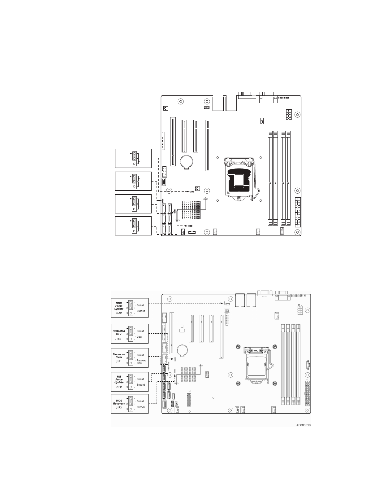
Configuration Jumpers
BIOS
Recovery
J2G1
Password
Clear
J1G1
Protected
RTC
J1H3
ME
Force
Update
J2J1
Default
2
Enabled
3
Default
2
Cleared
3
Default
2
Clear
3
Default
2
Enabled
3
AF003618
Figure 10. Configuration Jumper Locations (S1200BTS)
Figure 11. Configuration Jumper Locations
14 Intel® Server System R1304BTSSFAN/R1304BTLSFAN/R1304BTLSHBN Service Guide
Page 35

Jumper Name Jumper Purpose
BIOS Recovery Jumper in normal position (pins 1-2) allows normal system operation with
correct BIOS settings. System will POST normally.
Jumper in maintenance mode (pins 2-3) allows Intel
password reset.
Jumper removed is used to recover from a corrupted BIOS. Bootable
media with a valid BIOS ROM required.
Password Clear Jumper in normal position (pins 1-2) allows the system to successfully
POST and boot to the operating system environment. BIOS settings are
kept intact.
Jumper in clear position (pins 2-3) initiates a clearing of password.
®
AMT setting/
Protected RTC
(CMOS clear)
Jumper in normal position (pins 1-2) allows the system to successfully
POST and boot to the operating system environment. BIOS settings are
kept intact.
Jumper in clear position (pins 2-3) initiates a clearing of NVRAM following
POST. A system message confirms the Protected RTC (CMOS clear)
operation was successful. This setting enforces default BIOS settings,
which you can change by entering setup pressing F2, then exiting setup
pressing F10 and saving changes.
BMC Force
Update
Jumper in normal position (pins 1-2) disables BMC firmware force update.
Jumper in clear position (pins 2-3) allows BMC firmware force update.
ME Force Update Jumper in normal position (pins 1-2) disables ME firmware force update.
Jumper in clear position (pins 2-3) allows ME firmware force update.
Intel® Server System R1304BTSSFAN/R1304BTLSFAN/R1304BTLSHBN Service Guide 15
Page 36

Hardware Requirements
To avoid integration difficulties and possible board damage, your system must meet the
following requirements outlined. For a list of qualified components, see the links under
“Server System References” on page xi.
Processor
For a complete list of supported processors, see the links under “Server System
References” on page xi.
Memory
The Intel® Server Board S1200BTS/S1200BTL supports a DDR3-based memory subsystem. The server board supports up to two DIMM sockets per channel.
Refer to the following table for
channel slot configuratoin. For a complete list of
supported memory DIMMs, see the links under “Server System References” on page xi.
Table 4. Memory Configuration Table
Configuration DIMM_A1 DIMM_A2 DIMM_B1 DIMM_B2
1 DIMM Single
Channel
1 DIMM Single
Channel
2 DIMMs Single
Channel
2 DIMMs Single
Channel
2 DIMMs Dual
Channel
Symmetric
3 DIMMs Intel®
Flex Memory
A1 only Single
Channel
A1 Single Channel A2 Single Channel
A1 Dual Channel
ymmetric
S
A1 Dual Channel
Symmetric
A2 Dual Channel
Asymmetric
B1 only Single
Channel
B1 Single Channel B2 Single Channel
B1 Dual Channel
Symmetric
B1 Dual Channel
Symmetric
3 DIMMs Intel®
Flex Memory
4 DIMMs Dual
Channel
Symm
etric
16 Intel® Server System R1304BTSSFAN/R1304BTLSFAN/R1304BTLSHBN Service Guide
A1 Dual Channel
Symmetric
A1 Dual Channel
S
ymmetric
A2 Dual Channel
Symmetric
B1 Dual Channel
Symmetric
B1 Dual Channel
Symmetric
B2 Dual Channel
Asymmetric
B2 Dual Channel
Symmetric
Page 37

The Independent Channel Mode is the default Maximum Performance Mode preferred for
®
Xeon® E3-1200 based platforms. All three channels may be populated in any order
Intel
and have no matching requirements. All channels must run at the same interface
frequency, but individual channels may run at different DIMM timings (RAS latency,
CAS latency, and so on).
Intel® Server System R1304BTSSFAN/R1304BTLSFAN/R1304BTLSHBN Service Guide 17
Page 38

18 Intel® Server System R1304BTSSFAN/R1304BTLSFAN/R1304BTLSHBN Service Guide
Page 39

2 Server Utilities
Using the BIOS Setup Utility
This section describes the BIOS Setup Utility options, which are used to change server
configuration defaults. You can run BIOS Setup with or without an operating system
present. See the links under
Server Board S1200BT Technical Product Specification where you will find details about
specific BIOS setup screens.
Starting Setup
You can enter and start BIOS Setup under several conditions:
“Server System References” on page xi for a link to the Intel®
• When you turn on the server, after POST completes the memory test.
• When you have moved the CMOS jumper on the server board to the “Clear CMOS”
position (enabled).
In the two conditions listed previously, during the Power On Self Test (POST), you will
see this prompt:
Press <F2> to enter SETUP
In a third condition, when CMOS/NVRAM is corrupted, you will see other prompts but
not the <F2> prompt:
Warning: CMOS checksum invalid
Warning: CMOS time and date not set
In this condition, the BIOS loads the default values for CMOS and attempts to boot.
If You Cannot Access Setup
If you cannot access the BIOS Setup, you might need to clear the CMOS memory. For
instructions on clearing the CMOS, see
Setup Menus
“Clearing the CMOS” on page 24.
Each BIOS Setup menu page contains a number of features. Except for those features that
are provided only to display automatically configured information, each feature is
associated with a value field that contains user-selectable parameters. A user can change
these parameters if they have adequate security rights. If a value cannot be changed for
any reason, the feature's value field is inaccessible.
Intel® Server System R1304BTSSFAN/R1304BTLSFAN/R1304BTLSHBN Service Guide 19
Page 40

“Setup Menu Key Use” describes the keyboard commands you can use in the BIOS
Setup menus.
Table 5. Setup Menu Key Use
Key to Press Description
<F1> Pressing the <F1> key on any menu opens the general help window.
Left and right arrows The left and right arrow keys are used to move between the major menu
pages. The keys have no effect if a submenu or pick list is displayed.
Up arrow Select Item up - The up arrow is used to select the previous value in a
menu item's option list, or a value field pick list. Pressing <Enter>
activates the selected item.
Down arrow Select Item down - The down arrow is used to select the next value in a
menu item's option list, or a value field pick list. Pressing <Enter>
activates the selected item.
<F5> or <-> Change Value - The minus key or the <F5> function key is used to
change the value of the current item to the previous value. This key
scrolls through the values in the associated pick list without displaying
the full list.
<F6> or <+> Change Value - The plus key or the <F6> function key is used to change
the value of the current menu item to the next value. This key scrolls
through the values in the associated pick list without displaying the full
list. On 106-key Japanese keyboards, the plus key has a different scan
code than the plus key on the other keyboard, but it has the same effect.
<Enter> Execute Command - The <Enter> key is used to activate submenus
when the selected feature is a submenu, or to display a pick list if a
selected feature has a value field, or to select a sub-field for multi-valued
features like time and date. If a pick list is displayed, pressing <Enter>
will undo the pick list, and allow another selection in the parent menu.
<Esc> Exit - The <Esc> key provides a mechanism for backing out of any field.
<F9> Setup Defaults - Pressing <F9> causes the following to display:
This key will undo the pressing of the <Enter> key. When <Esc> is
pressed while editing any field or selecting features of a menu, the
parent menu is re-entered. When <Esc> is pressed in any submenu, the
parent menu is re-entered. When <Esc> is pressed in any major menu,
the exit confirmation window displays and the user is asked whether they
want to discard their changes.
Setup Confirmation
Load default configuration now?
[Yes] [No]
If “Yes” is selected and <Enter> is pressed, all Setup fields are set to
their default values. If “No” is selected and <Enter> is pressed, or <Esc>
is pressed, the user is returned to where they were before <F9> was
pressed without affecting any existing field values.
20 Intel® Server System R1304BTSSFAN/R1304BTLSFAN/R1304BTLSHBN Service Guide
Page 41

Key to Press Description
<F10> Save and Exit - Pressing <F10> causes the following message to
display:
If “Yes” is selected and <Enter> is pressed, all changes are saved and
Setup is exited. If “No” is selected and <Enter> is pressed, or <Esc> is
pressed, the user is returned to where they were before <F10> was
pressed without affecting any existing values.
Upgrading the BIOS
The upgrade utility allows you to upgrade the BIOS in flash memory. The code and data in
the upgrade file include the following:
Table 5. Setup Menu Key Use
Setup Confirmation
Save Configuration changes and exit now?
[Yes] [No]
• On-board system BIOS, including the recovery code, BIOS Setup Utility,
and strings.
• On-board video BIOS, and other option ROMs for devices embedded on the
server board.
• OEM binary area
• Microcode
Preparing for the Upgrade
The following steps explain how to prepare to upgrade the BIOS, including how to record
the current BIOS settings and obtain the upgrade utility.
Note: In the unlikely event that a BIOS error occurs during the BIOS update process, you may
need to follow a recovery process to return the system to service. See
References” on page xi for a link to necessary software and instructions.
Recording the Current BIOS Settings
1. Boot the computer and press <F2> when you see the following message:
Press <F2> Key if you want to run SETUP
2. Write down the current settings in the BIOS Setup program.
“Server System
Note: Do not skip Step 2. You need these settings to configure your server at the end of
the procedure.
Intel® Server System R1304BTSSFAN/R1304BTLSFAN/R1304BTLSHBN Service Guide 21
Page 42

Obtaining the Upgrade
Download the BIOS image file to a temporary folder on your hard drive. See “Server
System References” on page xi for a link to the update software.
Note: Before attempting a BIOS upgrade, review the instructions and release notes provided in
the readme file distributed with the BIOS image file. The release notes contain critical
information regarding jumper settings, specific fixes, and other information to complete
the upgrade.
Upgrading the BIOS
Follow the instructions in the readme file that came with the BIOS upgrade. When the
update completes, remove the bootable media from which you performed the upgrade.
Caution: Do not power down the system during the BIOS update process!
Note: You may encounter a CMOS Checksum error or other problem after reboot. If this
happens, shut down the system and boot it again. CMOS checksum errors require that you
enter Setup, check your settings, save your settings, and exit Setup.
Recovering the BIOS
If an update to the system BIOS is not successful or if the system fails to complete POST
and the BIOS is unable to boot an operating system, it may be necessary to run the BIOS
recovery procedure.
To place the baseboard into recovery mode, move the boot option jumper (located on the
baseboard) to the recovery position. The BIOS can then execute the recovery BIOS (also
known as the boot block) instead of the normal BIOS. The recovery BIOS is a selfcontained image that exists solely as a fail-safe mechanism for installing a new
BIOS image.
Note: During the recovery mode, video is not initialized. One high-pitched beep announces the
start of the recovery process. The entire process takes two to four minutes. A successful
update ends with two high-pitched beeps. Failure is indicated by a long series of
short beeps.
Recovering the BIOS
The following steps boot the recovery BIOS and flashes the normal BIOS:
1. Power down and unplug the system from the AC power source.
2. Move the recovery jumper from the default location at pins 1 and 2 to cover pins 2
and 3. For location of the jumper, see “Configuration Jumpers” on page 14.
22 Intel® Server System R1304BTSSFAN/R1304BTLSFAN/R1304BTLSHBN Service Guide
Page 43

3. Insert the bootable BIOS Recovery media containing the new BIOS image files.
A BIOS recovery can be accomplished from SATA CD and USB Mass Storage
device. Please note this platform does not support recovery from a USB floppy.
The recovery media must contain the following files under the root directory:
✧ FVMAIN.FV
✧ UEFI iFlash32
✧ *Rec.CAP
✧ Startup.nsh (update accordingly to use proper *Rec.CAP file)
4. Plug the system into the AC power source and power it on.
5. The BIOS POST screen will appear displaying the progress, and the system will
automatically boot to the EFI SHELL.
6. Remove the recovery media.
7. Power down and unplug the system from the AC power source.
8. Move the BIOS recovery jumper back to the original position, covering pins
1 and 2.
9. Plug the system into the AC power source and power it up to confirm the recovery
was successful.
10. Do NOT interrupt the BIOS POST during the first boot.
Clearing the Password
11. If the user or administrator password(s) is lost or forgotten, moving the password
clear jumper into the “clear” position clears both passwords. Before a new
password(s) is set, you must restore the password clear jumper to its original
position. For location of the jumper, see “Configuration Jumpers” on page 14.
1. Power down the system and disconnect the AC power.
2. Open the server chassis.
3. Move the jumper from the normal operation position, Password Clear Protect, at
pins 1 and 2 to the Password Clear Erase position, covering pins 2 and 3.
4. Reconnect the AC power, power up the system.
5. Power down the system and disconnect the AC power.
6. Return the Password Clear jumper to the Password Clear Protect position, covering
pins 1 and 2.
7. Reconnect the AC power and power up the server.
8. Close the server chassis. The password is cleared and can be reset by going into the
BIOS setup.
Intel® Server System R1304BTSSFAN/R1304BTLSFAN/R1304BTLSHBN Service Guide 23
Page 44

Clearing the CMOS
9. If you cannot access the BIOS setup screens, you must use the Protected RTC
(CMOS clear) jumper to reset the configuration RAM. For location of the jumper,
see “Configuration Jumpers” on page 14.
1. Power down the system and disconnect the AC power.
2. Open the server chassis. For instructions, see your server chassis documentation.
3. Move the jumper from the default operating position (covering pins 1 and 2) to the
reset/clear position (covering pins 2 and 3).
4. Wait five seconds.
5. Move the jumper back to default position, covering pins 1 and 2.
6. Close the server chassis.
7. Reconnect the AC power and power up the system. The CMOS is cleared and can
be reset by going into the BIOS setup.
Updating the Integrated BMC
8. When performing the standard Integrated BMC firmware update procedure, the
update utility places the Integrated BMC into an update mode, allowing the
firmware to load safely onto the flash device. In the unlikely event the Integrated
BMC firmware update process fails (due to the Integrated BMC not being in the
proper update state), the server board provides an Integrated BMC Force Update
jumper, which forces the Integrated BMC into the proper update state. You should
complete the following procedure in the event the standard Integrated BMC
firmware update process fails. For location of the jumper, see “Configuration
Jumpers” on page 14.
Note: Normal Integrated BMC functionality is disabled with the Force Integrated BMC Update
jumper set to the enabled position. The server should never be run with the Integrated
BMC Force Update jumper set in this position. This jumper setting should only be used
when the standard firmware update process fails. This jumper should remain in the
default/disabled position when the server is running normally.
1. Power down and remove the AC power cord.
2. Open the server chassis. For instructions, refer to your server chassis
documentation.
3. Move the jumper from the default operating position (covering pins 1 and 2) to the
enabled position (covering pins 2 and 3).
4. Close the server chassis.
5. Reconnect the AC cord and power up the server.
6. Perform the Integrated BMC firmware update procedure as documented in the
README.TXT file included in the given Integrated BMC firmware update
package. After successful completion of the firmware update process, the firmware
24 Intel® Server System R1304BTSSFAN/R1304BTLSFAN/R1304BTLSHBN Service Guide
Page 45

update utility may generate an error stating the Integrated BMC is still in
update mode.
7. Power down and remove the AC power cord.
8. Open the server chassis.
9. Move jumper from the enabled position (covering pins 2 and 3) to the disabled
position (covering pins 1 and 2).
10. Close the server chassis.
11. Reconnect the AC cord and power up the server.
Updating ME Firmware
When performing the standard ME force update procedure, the update utility places the
ME into an update mode, allowing the ME to load safely onto the flash device. In the
unlikely event ME firmware update process fails due to ME not being in the proper update
state, the server board provides an Integrated BMC Force Update jumper, which forces the
ME into the proper update state. The following procedure should be completed in the
event the standard ME firmware update process fails.
1. Power down and remove the AC power cord.
2. Open the server chassis. For instructions, see your server chassis documentation.
3. Move jumper from the default operating position (covering pins 1 and 2) to the
enabled position (covering pins 2 and 3).
4. Close the server chassis.
5. Reconnect the AC cord and power up the server.
6. Perform the ME firmware update procedure as documented in the README.TXT
file that is included in the given ME firmware update package (same package
as BIOS).
7. Power down and remove the AC power cord.
8. Open the server chassis.
9. Move jumper from the enabled position (covering pins 2 and 3) to the disabled
position (covering pins 1 and 2).
10. Close the server chassis.
11. Reconnect the AC cord and power up the server.
Intel® Server System R1304BTSSFAN/R1304BTLSFAN/R1304BTLSHBN Service Guide 25
Page 46

26 Intel® Server System R1304BTSSFAN/R1304BTLSFAN/R1304BTLSHBN Service Guide
Page 47

3 Hardware Installations and
Upgrades
Caution: No components in the Intel® Server System R1304BTSSFAN/R1304BTLSFAN are hot-
swappable. Before removing or installing any component in this server system, you must
first take the server out of service, turn off all peripheral devices connected to the system,
turn off the system by pressing the power button, and unplug the AC power cord from the
system or wall outlet.
Note: Some components in the Intel® Server System R1304BTLSHBN are hot-swappable and
are noted as such (where applicable) in the following instructions.
Note: Most of the illustrations in this chapter show the Intel® Server System R1304BTLSFAN
with an optional optical drive installed. Unless otherwise noted, the instructions for
removing and installing components are the same for the Intel
R1304BTSSFAN/R1304BTLSHBN. When instructions differ, separate illustrations are
shown for the Intel
®
Server System R1304BTSSFAN or R1304BTLSHBN.
®
Server System
Before You Begin
Before working with your server product, pay close attention to the “Safety Information”
on page iii.
Tools and Supplies Needed
• Phillips* (cross head) screwdriver, #1 bit and #2 bit
• Antistatic wrist strap and conductive foam pad (recommended)
System References
All references to the left, right, front, top, and bottom assume the reader is facing the front
of the server system as it would be positioned for normal operation.
Intel® Server System R1304BTSSFAN/R1304BTLSFAN/R1304BTLSHBN Service Guide 27
Page 48

AF003681
C
A
B
B
Removing and Installing the Server Cover
Removing the Server System Cover
You must operate the server system with the server system cover in place to ensure proper
cooling. You must remove the cover to add or replace components inside of the server.
None of the internal components are hot-swappable. Before removing the server system
, power down the server and unplug all peripheral devices and the AC power cable.
cover
Note: Y
ou may need a non-skid surface or a stop behind the server system to prevent the server
system from sliding on your work surface.
1. Observe the safety and ESD precautions at the beginning of this book. See “Safety
Information” on page iii.
2. Turn off all peripheral devices connected to the server. Turn off the server.
3. Disconnect the AC power cord.
4. Remove the screw at the front of the chassis. See letter “A” in Figure 12.
5. Push down the two buttons, then push rearward. See letter "B" in Figure 15. Slide
the cover back until it stops and then lift the cover upward to remove it. See letter
“C” in Figure 12.
Figure 12. Removing the Server System Cover
28 Intel® Server System R1304BTSSFAN/R1304BTLSFAN/R1304BTLSHBN Service Guide
Page 49

Installing the Server System Cover
1. Observe the safety and ESD precautions at the beginning of this book. See “Safety
Information” on page iii.
2. Place the cover over the server system so that the side edges of the cover sit just
inside the server system sidewalls. Slide the cover forward. See letter “A” in
Figure 13.
3. Install the screw at the front of the server. See letter “B” in Figure 13.
Recessed
Edge
A
B
Figure 13. Installing the Server System Cover
4.
Reconnect all peripheral devices and the AC power cord.
AF003703
Intel® Server System R1304BTSSFAN/R1304BTLSFAN/R1304BTLSHBN Service Guide 29
Page 50

Removing and Installing the Processor Air Duct
Always operate your server system with the processor air duct in place. The air duct is
required for proper airflow within the server system.
Removing the Processor Air Duct
1. Observe the safety and ESD precautions at the beginning of this book. See “Safety
Information” on page iii.
2. Power down the server and unplug all peripheral devices and the AC power cable.
3. Remove the server system cover. For instructions, see “Removing the Server
System Cover” on page 28.
4. Lift the processor air duct from its location.
30 Intel® Server System R1304BTSSFAN/R1304BTLSFAN/R1304BTLSHBN Service Guide
Page 51

AF003701
Installing the Processor Air Duct
1. Observe the safety and ESD precautions at the beginning of this book. See “Safety
Information” on page iii.
2. Power down the server and unplug all peripheral devices and the AC power cable.
3. Remove the server system cover. For instructions, see “Removing the Server
System Cover” on page 28.
4. Lower the air duct into place,
insert the two hooks at the front of the processor air
duct into the corresponding slots on the bracket. Use caution not to pinch or
disengage cables that may be near or under the air duct.
5. Install the server system cover. For instructions, see “Installing the Server System
Cover” on page 29.
Figure 14. Installing the Processor Air Duct
Intel® Server System R1304BTSSFAN/R1304BTLSFAN/R1304BTLSHBN Service Guide 31
Page 52

Installing and Removing Memory
Caution: The memory is NOT hot-swappable. Before removing or replacing any memory DIMM,
you must first take the server out of service, turn off all peripheral devices connected to
the system, turn off the system by pressing the power button, and unplug the AC power
cord from the system or wall outlet.
The silkscreen on the board for the DIMMs displays DIMM A1, DIMM A2, DIMM B1,
and DIMM B2 starting from the center of the board. See
discussion of the memory requirements and options. See “Server System References” on
page xi for a link to the list of tested DIMMs.
“Memory” on page 16 for a
32 Intel® Server System R1304BTSSFAN/R1304BTLSFAN/R1304BTLSHBN Service Guide
Page 53

Installing DIMMs
To install DIMMs, follow these steps:
1. Observe the safety and ESD precautions at the beginning of this book. See “Safety
Information” on page iii.
2. Power down the server and unplug all peripheral devices and the AC power cable.
3. Remove the server system cover. For instructions, see “Removing the Server
System Cover” on page 28.
4. Locate the DIMM sockets. See Figure 15.
5. Make sure the clips at both ends of the DIMM socket(s) are pushed outward to the
open position. See letter “A” in Figure 15.
6. Holding the DIMM by the edges, remove it from its anti-static package.
7. Position the DIMM above the socket. Align the notch on the bottom edge of the
DIMM with the key in the DIMM socket. See letter “B” in Figure 15.
8. Insert the bottom edge of the DIMM into the socket. See letter “C” in Figure 15.
9. When the DIMM is correctly positioned, push down on the top edge of the DIMM
until the retaining clips snap into place.
10. Make sure the clips are firmly in place. See letter “D” in Figure 15.
11. Install the server system cover. For instructions, see “Installing the Server System
Cover” on page 29.
Removing DIMMs
To remove a DIMM, follow these steps:
1. Observe the safety and ESD precautions at the beginning of this book. See “Safety
Information” on page iii.
Figure 15. Installing the Memory
Intel® Server System R1304BTSSFAN/R1304BTLSFAN/R1304BTLSHBN Service Guide 33
Page 54

2. Power down the server and unplug all peripheral devices and the AC power cable.
3. Remove the server system cover. For instructions, see “Removing the Server
System Cover” on page 28.
4. Locate the DIMM sockets. See Figure 15.
5. Gently spread the retaining clips at each end of the socket. The DIMM lifts from
the socket.
6. Holding the DIMM by the edges, lift it from the socket, and store it in an anti-static
package.
7. Install the server system cover. For instructions, see “Installing the Server System
Cover” on page 29.
34 Intel® Server System R1304BTSSFAN/R1304BTLSFAN/R1304BTLSHBN Service Guide
Page 55

Replacing the Processor
Note: This manual assumes a processor is already installed and you are referring to these steps
to replace your processor. If you are setting up this system for the first time, see the Quick
Start User’s Guide included in the product box.
Caution: Use only processors validated to work with this server board. See “Server System
References” on page xi for a link to the list of compatible processor(s).
Caution: ESD and handling processors: Reduce the risk of electrostatic discharge (ESD) damage to
the processor by doing the following: (1) Touch the metal chassis before touching the
processor or server board. Keep part of your body in contact with the metal chassis to
dissipate the static charge while handling the processor. (2) Avoid moving around
unnecessarily.
Removing the Heat Sink and Processor
1. Observe the safety and ESD precautions at the beginning of this book. See “Safety
Information” on page iii.
2. Power down the server and unplug all peripheral devices and the AC power cable.
3. Remove the server system cover. For instructions, see “Removing the Server
System Cover” on page 28.
4. Loosen the four captive screws on the corners of the heat sink.
5. Twist the heat sink slightly to break the seal between the heat sink and the
processor.
6. Lift the heat sink from the processor. If it does not pull up easily, twist the heat sink
again. Do not force the heat sink from the processor. Doing so could damage the
processor.
7. Lift the processor lever.
8. Raise the CPU load plate.
9. Remove the processor.
10. If installing a replacement processor, see “Installing the Processor” on page 36.
Otherwise, install the protective socket cover over the empty processor socket and
then reinstall the chassis cover.
Intel® Server System R1304BTSSFAN/R1304BTLSFAN/R1304BTLSHBN Service Guide 35
Page 56

Installing the Processor
To install a processor, follow these instructions:
1. Observe the safety and ESD precautions at the beginning of this book. See “Safety
Information” on page iii.
2. Power down the server and unplug all peripheral devices and the AC power cable.
3. Remove the server system cover. For instructions, see “Removing the Server
System Cover” on page 28.
4. Locate the processor socket and raise the socket handle completely. See Figure 16.
REMOVE
A
B
AF003186
Figure 16. Lifting the Processor Socket Handle
5. Push the rear tab with your finger to slightly lift the front of the load plate. Raise the
load plate completely. Raise the CPU load plate (see Figure 17).
36 Intel® Server System R1304BTSSFAN/R1304BTLSFAN/R1304BTLSHBN Service Guide
Page 57

REMOVE
AF003187
REMOVE
A
B
Figure 17. Opening the Load Plate
Caution: Do not touch the socket pins; they are very sensitive and easily damaged.
6. Remove the processor from the packaging box and remove the protective shipping
cover. See Figure 18.
A
AF003189
Figure 18. Removing the Shipping Cover
Intel® Server System R1304BTSSFAN/R1304BTLSFAN/R1304BTLSHBN Service Guide 37
Page 58

7. Orient the processor with the socket so the processor cutouts match the socket
notches. See letter “A” in Figure 19.
8. Set the processor into place as shown by letter “B” in Figure 19.
A
AF003190
Figure 19. Installing the Processor
Note: Make sure the alignment triangle mark and the alignment triangle cutout align correctly.
9. Remove the protective socket cover. See Figure 20.
Figure 20. Removing the Protective Socket Cover
Note: Retain the protective socket cover for use when removing a processor that will not be
replaced.
10. Lower the CPU load plate.
11. Lower the socket lever.
12. Install the heat sink. For instructions, see “Installing the Heat Sink” on page 39.
38 Intel® Server System R1304BTSSFAN/R1304BTLSFAN/R1304BTLSHBN Service Guide
Page 59

Installing the Heat Sink
Before installing the heat sink, you must install your processor. For instructions, see
“Installing the Processor” on page 36.
Caution: The heat sink has The
caution when you unpack the heat sink so you do not damage the TIM.
1. Remove the protective cover from the TIM on the underside of the heat sink. Do
not touch the TIM.
2. Orient the heat sink over the processor as shown in Figure 21. You must position
the fins as shown to provide correct airflow through the system.
3. Set the heat sink over the processor, lining up the four captive screws with the four
posts surrounding the processor.
4. Loosely screw in the captive screws on the heat sink corners in a diagonal manner
as shown by the four circled numbers in Figure 21. Do not fully tighten one screw
before tightening another.
5. Gradually and equally tighten each captive screw in the same order until each is
firmly tightened.
rmal Interface Material (TIM) located on the bottom of it. Use
AIRFLOW
2
3
1
4
Chassis
Front
AF001049
Figure 21. Installing the Heat Sink
6. Reinstall and reconnect any parts you remove
d or disconnected to reach the
processor sockets.
Intel® Server System R1304BTSSFAN/R1304BTLSFAN/R1304BTLSHBN Service Guide 39
Page 60

7. Install the server system cover. For instructions, see “Installing the Server System
Cover” on page 29.
40 Intel® Server System R1304BTSSFAN/R1304BTLSFAN/R1304BTLSHBN Service Guide
Page 61

Installing and Removing a Hard Drive (R1304BTSSFAN/R1304BTLSFAN)
Caution: The hard drives are NOT hot-swappable. Before removing or replacing a hard drive, you
must first take the server out of service, turn off all peripheral devices connected to the
system, turn off the system by pressing the power button, and unplug the AC power cord
from the system or wall outlet.
You can install up to four SATA drives. The HDD0 drive bay is at the left side of the
chassis. The HDD1 drive bay is at the right side of HDD0. You do not need to install the
drives in order; you can install HDD1, HDD2, or HDD3 before HDD0.
Note: The server system does not support all hard drives. See “Server System References” on
page xi for an Internet link to a list of supported hardware.
Installing a Hard Disk Drive (R1304BTSSFAN/ R1304BTLSFAN)
Note: If you are replacing a hard drive, see “Installing and Removing a Hard Drive
(R1304BTSSFAN/R1304BTLSFAN)” on page 41 for instructions first. Return to these
steps when directed.
1. Observe the safety and ESD precautions at the beginning of this book. See “Safety
Information” on page iii.
2. Power down the server. Unplug all peripheral devices and the AC power cable.
3. Remove the server system cover. For instructions, see “Removing the Server
System Cover” on page 28.
4. Locate the drive position you want to use.
5. Remove the screws that holds the hard drive bracket to the chassis. See letter “A” in
Figure 22. Save the screws. You will use them to reinstall the drive assembly later.
6. Slide-out the drive carrier from the chassis. See letter “B” in Figure 22.
Intel® Server System R1304BTSSFAN/R1304BTLSFAN/R1304BTLSHBN Service Guide 41
Page 62

AF003684
Screw
A
B
C
Figure 22. Removing Drive Carrier from the Server System (R1304BTLSFAN)
7. Insert hard drive into the carrier with the bottom-side of the drive facing up.
8. Attach the hard drive to the carrier with four screws as shown.
9. Re-install the hard drive/carrier assembly into the chassis.
D
AF003686
Figure 23. Installing Drive into Drive Carrier (R1304BTSSFAN/
R1304
10. Secure the hard drive/carrier assembly with the screws.
11. Connect the data cables to the drive(s).
12. Connect the power cables to the drive(s).
13. Install the server system cover. For instructions, see “Installing the Server System
Cover” on page 29.
BTLSFAN)
42 Intel® Server System R1304BTSSFAN/R1304BTLSFAN/R1304BTLSHBN Service Guide
Page 63

Removing a Hard Disk Drive (R1304BTSSFAN/ R1304BTLSFAN)
1. Observe the safety and ESD precautions at the beginning of this book. See “Safety
Information” on page iii.
2. Power down the server and unplug all peripheral devices and the AC power cable.
3. Remove the server system cover. For instructions, see “Removing the Server
System Cover” on page 28.
4. Disconnect the power and data cables from the drive.
5. Remove the screws that holds the hard drive bracket to the chassis. Save this screw.
You will use it to reinstall the drive assembly later.
6. Remove the drive carrier from the chassis.
7. Remove the four screws that attach the hard drive to the drive carrier. Lift the drive
from the carrier. Store the drive in an anti-static bag.
8. If you are installing a new drive, skip the rest of these steps and instead see
“Installing and Removing a Hard Drive (R1304BTSSFAN/R1304BTLSFAN)” on
page 41, beginning with step 7.
9. Insert the screws that held the drive in the carrier into the screw-locations on the
carrier for future use.
10. Set the drive assembly into place in the chassis.
11. Attach the drive assembly to the chassis with the screws that you removed
in Step 5.
Note: You must install the assembly that contains the optical drive bracket at the left side of
the system.
12. Install the server system cover. For instructions, see “Installing the Server System
Cover” on page 29.
Intel® Server System R1304BTSSFAN/R1304BTLSFAN/R1304BTLSHBN Service Guide 43
Page 64

A
B
Installing and Removing a Hot-Swap SATA Drive (R1304BTLSHBN)
You can install up to three hot swappable SATA drives. The HDD0 drive bay is at the left
side. You do not need to install the drives in order; you can install HDD1 before HDD0.
Cautions: If you install less than four drives or devices, the empty drive bays must be occupied by
carriers with baffles to maintain proper system cooling.
Note: The server system does not support all hard drives. See “Server System References” on
page xi for an Internet link to a list of supported hardware.
Installing a Hot-Swap SATA Drive (R1304BTLSHBN)
1. If it is installed, remove the front bezel.
2. Locate the drive position you want to use.
3. Open the latch at the front of the hard drive carrier. See letter "A" in Figure 24.
Figure 24. Removing the Drive Carrier (R1304BTLSHBN)
4. Pull out on the black lever and slide the carrier from the server system.
5. Remove the four screws that attach the plastic retention device or the previously
installed hard drive to the drive carrier. Two screws are at each side of the retention
device or the hard drive. Store the plastic retention device for future use.
6. Remove the hard drive from its wrapper and place it on an antistatic surface.
7. Set any jumpers and/or switches on the drive according to the drive
manufacturer's instructions.
44 Intel® Server System R1304BTSSFAN/R1304BTLSFAN/R1304BTLSHBN Service Guide
Page 65

AF003721
TOP
BREAK OFF TAB
BEFORE MOUTING
2.5´´ HARD DRIVE
AF003722
D
3.5´´ HDD
8. With the drive circuit-side down, position the connector end of the drive so it is
facing the rear of the drive carrier.
9. Align the holes in the drive to the holes in the drive carrier and attach it to the
carrier with the screws that were attached to the plastic retention device. See letter
“D” in Figure 25.
Figure 25. Installing Drive into Drive Carrier (R1304BTLSHBN)
10. With the black lever in the fully open position, slide the drive assembly into the
server system (see letter “E” in Figure 26). The green latch at the front of the drive
carrier must be to the right. Do not push on the black drive carrier lever until the
lever begins to close by itself.
11. When the black drive carrier lever begins to close by itself, push on it to lock the
drive assembly into place (see letter “F” in Figure 26).
Intel® Server System R1304BTSSFAN/R1304BTLSFAN/R1304BTLSHBN Service Guide 45
Page 66

E
F
AF003723
Figure 26. Install Drive Assembly into the Server System (R1304BTLSHBN)
12. Install the server
Cover” on page 29.
13. (Optional) Install the front bezel.
14. Plug all peripheral devices and the AC power cable into the server.
system cover. For instructions, see “Installing the Server System
Removing a Hot-Swap SATA Drive (R1304BTLSHBN)
1. If it is installed, remove the front bezel. For instructions.
2. Press in on the green latch at the front of the hard drive carrier.
3. Pull out on the black lever to slide the carrier from the server system.
4. Remove the four screws that attach the hard drive to the drive carrier. Lift the drive
from the carrier. Store the drive in an anti-static bag.
5. If you are not installing a new drive, place the plastic retention device into the drive
carrier, using the four screws you removed from the hard drive.
6. Insert the screws that held the drive in the carrier into the screw locations on the
carrier for future use.
7. With the black lever in the fully open position, slide the drive carrier into the server
system. The green latch must be to the right. Do not push on the black lever until
the lever begins to close by itself.
46 Intel® Server System R1304BTSSFAN/R1304BTLSFAN/R1304BTLSHBN Service Guide
Page 67

Note: For proper airflow, you must replace the hard drive carrier in the server system, even if no
hard drive is installed in it.
8. When the black lever begins to close by itself, push on it to lock the drive carrier
into place.
9. Install the server system cover. For instructions, see “Installing the Server System
Cover” on page 29.
10. (Optional) Install the front bezel.
11. Plug all peripheral devices and the AC power cable into the server.
Intel® Server System R1304BTSSFAN/R1304BTLSFAN/R1304BTLSHBN Service Guide 47
Page 68

B
A
AF003724
Installing or Removing a Slimline Optical Drive
Caution: The optical drive is NOT hot-swappable. Before removing or replacing the optical drive,
you must first take the server out of service, turn off all peripheral devices connected to
the system, turn off the system by pressing the power button, and unplug the AC power
cord from the system or wall outlet.
Installing a Slimline Optical Drive
Notes:
• If you are replacing an optical drive, see “Installing a Slimline Optical Drive” on
page 48 for instructions first. Return to these steps when directed.
1. Observe the safety and ESD precautions at the beginning of this book. See “Safety
Information” on page iii.
2. Power down the server and unplug all peripheral devices and the AC power cable.
3. Remove two screws secured the Filler Panel.
4. Remove the Filler Panel.
Figure 27. Removing the Knock-out from the Sheet Metal Panel
5. Attach the latch to the optical drive as shown, using two screws.
48 Intel® Server System R1304BTSSFAN/R1304BTLSFAN/R1304BTLSHBN Service Guide
Page 69

AF003700
B
AF003702
Optical
Device Tray
Assembly
Rear View
of Optical
Drive
Figure 28. Attaching the latch to the Optical Drive
6. Pull the power and data cables through the front of the chassis opening.
7. Connect the mini SATA power connector on the optical drive.
8. Connect the data cable to the optical drive and to the SATA connector on the
server board.
9. Slide the optical drive assembly in, through the front of the chassis.
Figure 29. Installing the Optical Drive into the System
10. Install the server system cover. For instructions, see “Installing the Server System
Cover” on page 29.
11. Plug all peripheral devices and the AC power cable into the server.
Intel® Server System R1304BTSSFAN/R1304BTLSFAN/R1304BTLSHBN Service Guide 49
Page 70

Removing a Slimline Optical Drive
1. Observe the safety and ESD precautions at the beginning of this book. See “Safety
Information” on page iii.
2. Power down the server and unplug all peripheral devices and the AC power cable.
3. Remove the server system cover. For instructions, see “Removing the Server
System Cover” on page 28.
4. Press down the latch and then Slide the optical drive out through the front of
the system.
5. Disconnect the optical drive power and data cables.
6. Remove the screws that secure the latch to the optical drive. Save these screws for
future use.
7. If you are installing a replacement optical drive, skip the rest of these steps and
instead continue with “Installing a Slimline Optical Drive” on page 48, Step 5 on
page 48.
8. Install the server system cover. For instructions, see “Installing the Server System
Cover” on page 29.
50 Intel® Server System R1304BTSSFAN/R1304BTLSFAN/R1304BTLSHBN Service Guide
Page 71

AF003683
Riser Card
Connector
Installing and Removing the PCIe* Riser Assembly
Caution: The PCIe* riser assembly is NOT hot-swappable. Before removing or replacing the PCIe*
riser assembly, you must first take the server out of service, turn off all peripheral devices
connected to the system, turn off the system by pressing the power button, and unplug the
AC power cord from the system or wall outlet.
Removing the PCIe* Riser Assembly
To remove the PCIe* riser assembly, use the following instructions.
1. Observe the safety and ESD precautions at the beginning of this book. See “Safety
Information” on page iii.
2. Power down the server and unplug all peripheral devices and the AC power cable.
3. Remove the server system cover. For instructions, see “Removing the Server
System Cover” on page 28.
4. Disconnect any cables attached to any add-in cards.
5. Lift riser assembly up to remove it. Use caution to gently ease the riser card from
the add-in card slot so you do not damage the slot or the riser card. See Figure 30.
Figure 30. Removing PCIe* Riser Assembly from the Server System
Intel® Server System R1304BTSSFAN/R1304BTLSFAN/R1304BTLSHBN Service Guide 51
Page 72

6. If you need to add or replace a PCIe* Riser connector, see “Installing and
Removing a PCI Add-in Card” on page 55.
7. If you need to add or replace a PCI add-in card, see “Installing and Removing a PCI
Add-in Card” on page 55.
8. If you removed the PCIe* Riser assembly for another procedure, continue with that
procedure.
Installing the PCIe* Riser Assembly
Note: For clarity, the figures in this series of instructions does not show an attached add-in
card. If you are installing an add-in card, do so before installing the PCIe* riser assembly
into your server system.
1. Lower the riser assembly into place over the add-in card slot. See letter “B” in
Figure 31.
2. Align the three hooks in the riser assembly with the matching slots at the back of
the server system. See letter “A” in Figure 31.
A
Riser Card
Connector
B
PCI Riser
Socket
AF003695
Figure 31. Installing PCIe* Riser Assembly into the Server System
3. Press down uniformly until the two hooks on the rear of the PCIe* riser assembly
engage the server system back panel slots. The riser cards will seat into the
matching sockets on the server board.
4. Connect any cables to add-in cards that require them. See your add-in card
documentation for information and add-in card requirements.
5. Install the server system cover. For instructions, see “Installing the Server System
Cover” on page 29.
52 Intel® Server System R1304BTSSFAN/R1304BTLSFAN/R1304BTLSHBN Service Guide
Page 73

AF003288
Installing or Replacing a PCIe* Riser Card
Caution: The PCIe* Riser card is NOT hot-swappable. Before removing or replacing the PCIe*
Riser card, you must first take the server out of service, turn off all peripheral devices
connected to the system, turn off the system by pressing the power button, and unplug the
AC power cord from the system or wall outlet.
You have the option to install one of two PCIe* Riser cards into your server system:
• A low-profile PCI Express* riser with one PCI Express x16 slot.
Note: To eliminate the possibility of installing the replacement connector on the wrong side of
the PCIe* Riser assembly, replace one connector at a time.
Removing a PCIe* Riser Card
1. Observe the safety and ESD precautions at the beginning of this book. See “Safety
Information” on page iii.
2. Power down the server and unplug all peripheral devices and the AC power cable.
3. Remove the server system cover. For instructions, see “Removing the Server
System Cover” on page 28.
4. Disconnect any cables attached to any add-in cards.
5. Remove the PCIe* Riser assembly. For instructions, see “Removing the PCIe*
Riser Assembly” on page 51.
6. Remove any add-in cards from the PCIe* Riser connector. For instructions, see
“Removing a PCI Add-in Card” on page 56.
7. Remove the two screws that attach the riser card to the riser assembly. See
Figure 32. Save these screws to be used later.
Figure 32. Removing Riser Card from Riser Assembly
8. Install the replacement riser connector, if desired. For instructions, see “Installing a
PCIe* Riser Card” on page 54.
9. Install the PCIe* Riser assembly into the server system. For instructions, see
“Installing the PCIe* Riser Assembly” on page 52.
Intel® Server System R1304BTSSFAN/R1304BTLSFAN/R1304BTLSHBN Service Guide 53
Page 74

AF003289
10. Install the server system cover. For instructions, see “Installing the Server System
Cover” on page 29.
11. Plug all peripheral devices and the AC power cable into the server.
Installing a PCIe* Riser Card
1. Observe the safety and ESD precautions at the beginning of this book. See “Safety
Information” on page iii.
2. Power down the server and unplug all peripheral devices and the AC power cable.
3. Remove the server system cover. For instructions, see “Removing the Server
System Cover” on page 28.
4. Disconnect any cables attached to any add-in cards.
5. Remove the PCIe* Riser assembly. For instructions, see “Removing the PCIe*
Riser Assembly” on page 51.
6. Remove any add-in cards from the PCIe* Riser connector. For instructions, see
“Removing a PCI Add-in Card” on page 56.
7. Use two screws to attach the riser card to the riser assembly. See Figure 33.
Figure 33. Installing Riser Card onto Riser Assembly
8. Install an PCI add-in card if desired. For instructions, see “Installing a PCI Add-in
Card” on page 55.
9. Install the PCIe* Riser assembly into the server system. For instructions, see
“Installing the PCIe* Riser Assembly” on page 52.
10. Connect any cables to add-in cards that require them. See your add-in card
documentation for information and add-in card requirements.
11. Re-install the processor air duct. For instructions, see “Installing the Processor Air
Duct” on page 31.
12. Install the server system cover. For instructions, see “Installing the Server System
Cover” on page 29.
13. Plug all peripheral devices and the AC power cable into the server.
54 Intel® Server System R1304BTSSFAN/R1304BTLSFAN/R1304BTLSHBN Service Guide
Page 75

Installing and Removing a PCI Add-in Card
Caution: The add-in cards are NOT hot-swappable. Before removing or replacing an add-in card,
you must first take the server out of service, turn off all peripheral devices connected to
the system, turn off the system by pressing the power button, and unplug the AC power
cord from the system or wall outlet.
Installing a PCI Add-in Card
1. Observe the safety and ESD precautions at the beginning of this book. See “Safety
Information” on page iii.
2. Power down the server and unplug all peripheral devices and the AC power cable.
3. Remove the server system cover. For instructions, see “Removing the Server
System Cover” on page 28.
4. Remove the PCIe* Riser assembly. For instructions, see “Removing the PCIe*
Riser Assembly” on page 51.
5. Remove the screw at the rear of the riser assembly. See letter “A” in Figure 34.
Save this screw. You will reinstall it later.
6. If a filler panel is installed over the opening at the rear of the riser assembly, lift it
from the riser assembly. See letter “B” in Figure 34. Save the filler panel in case
you later need to remove the add-in card.
7. Insert the add-in card into the socket in the riser assembly. Push the add-in card into
place firmly until it seats in the riser card connector, but use caution so you do not
twist or bend the card. See letter “C” in Figure 34.
8. Re-install the screw you removed in Step 5. See letter “A” in Figure 34.
Intel® Server System R1304BTSSFAN/R1304BTLSFAN/R1304BTLSHBN Service Guide 55
Page 76

AF003694
Riser Connector
REMOVE Filler Panel
A
B
Add-in Card
C
Figure 34. Installing an Add-In Card
9. Install the PCIe* Riser assembly into the server system. For instruc
“Installing the PCIe* Riser Assembly” on page 52.
10. Install the server system cover. For instructions, see “Installing the Server System
Cover” on page 29.
11. Plug all peripheral devices and the AC power cable into the server.
Removing a PCI Add-in Card
1. Observe the safety and ESD precautions at the beginning of this book. See “Safety
Information” on page iii.
2. Power down the server and unplug all peripheral devices and the AC power cable.
3. Remove the server system cover. For instructions, see “Removing the Server
4. Remove the PCIe* Riser assembly. For instructions, see “Removing the PCIe*
5. Remove the screw at the rear of the riser assembly. You will use it later.
6. Pull the add-in card from the socket in the riser assembly. You may need to wriggle
System Cover” on page 28.
Riser Assembly” on page 51.
the card from front to back to remove it, but use caution so you do not twist or bend
the card.
tions, see
7. Install a filler panel over the opening at the rear of the riser assembly.
56 Intel® Server System R1304BTSSFAN/R1304BTLSFAN/R1304BTLSHBN Service Guide
Page 77

8. Re-install the screw you removed in step 5.
Note: Make sure that all empty add-in card slots have filler panels installed.
9. Install the PCIe* Riser assembly into the server system. For instructions, see
“Installing the PCIe* Riser Assembly” on page 52.
10. Install the processor air duct. For instructions, see “Installing the Processor Air
Duct” on page 31.
11. Install the server system cover. For instructions, see “Installing the Server System
Cover” on page 29.
12. Plug all peripheral devices and the AC power cable into the server.
Intel® Server System R1304BTSSFAN/R1304BTLSFAN/R1304BTLSHBN Service Guide 57
Page 78

Replacing the Server Board
Removing the Server Board
1. Observe the safety and ESD precautions at the beginning of this book. See “Safety
Information” on page iii.
2. Power down the server and unplug all peripheral devices and the AC power cable.
3. Remove the server system cover. For instructions, see “Removing the Server
System Cover” on page 28.
4. Remove the processor air duct. For instructions, see “Removing the Processor Air
Duct” on page 30.
5. Remove the PCIe* Riser assembly. For instructions, see “Removing the PCIe*
Riser Assembly” on page 51.
6. Detach all cables connected to the server board.
7. Remove the heat sink and the processor. For instructions, see “Removing the Heat
Sink and Processor” on page 35.
8. Remove the DIMMs. For instructions, see “Removing DIMMs” on page 33.
9. Remove the nine screws from the server board and lift the server board from the
server system.
A
B
AF003739
Figure 35. Removing the Server Board
58 Intel® Server System R1304BTSSFAN/R1304BTLSFAN/R1304BTLSHBN Service Guide
Page 79

10. Replace the server board. For instructions, see “Installing the Server Board” on
page 59.
11. Install the processor. For instructions, see “Installing the Processor” on page 36.
12. Install the DIMMs. For instructions, see “Installing DIMMs” on page 33.
13. Install the PCIe* Riser assembly. For instructions, see “Installing the PCIe* Riser
Assembly” on page 52.
14. Reconnect all cables to the server board.
15. Install the processor air duct. For instructions, see “Installing the Processor Air
Duct” on page 31.
16. Install the server system cover. For instructions, see “Installing the Server System
Cover” on page 29.
17. Plug all peripheral devices and the AC power cable into the server.
Installing the Server Board
1. Observe the safety and ESD precautions at the beginning of this book. See “Safety
Information” on page iii.
2. Power down the server and unplug all peripheral devices and the AC power cable.
3. Remove the server system cover. For instructions, see “Removing the Server
System Cover” on page 28.
4. Remove the processor air duct. For instructions, see “Removing the Processor Air
Duct” on page 30.
5. Remove the PCIe* Riser assembly. For instructions, see “Removing the PCIe*
Riser Assembly” on page 51.
6. Place the server board into the server system as shown by letter “A” in Figure 36.
7. Attach the server board with nine screws. See letter “B” in Figure 36.
Intel® Server System R1304BTSSFAN/R1304BTLSFAN/R1304BTLSHBN Service Guide 59
Page 80
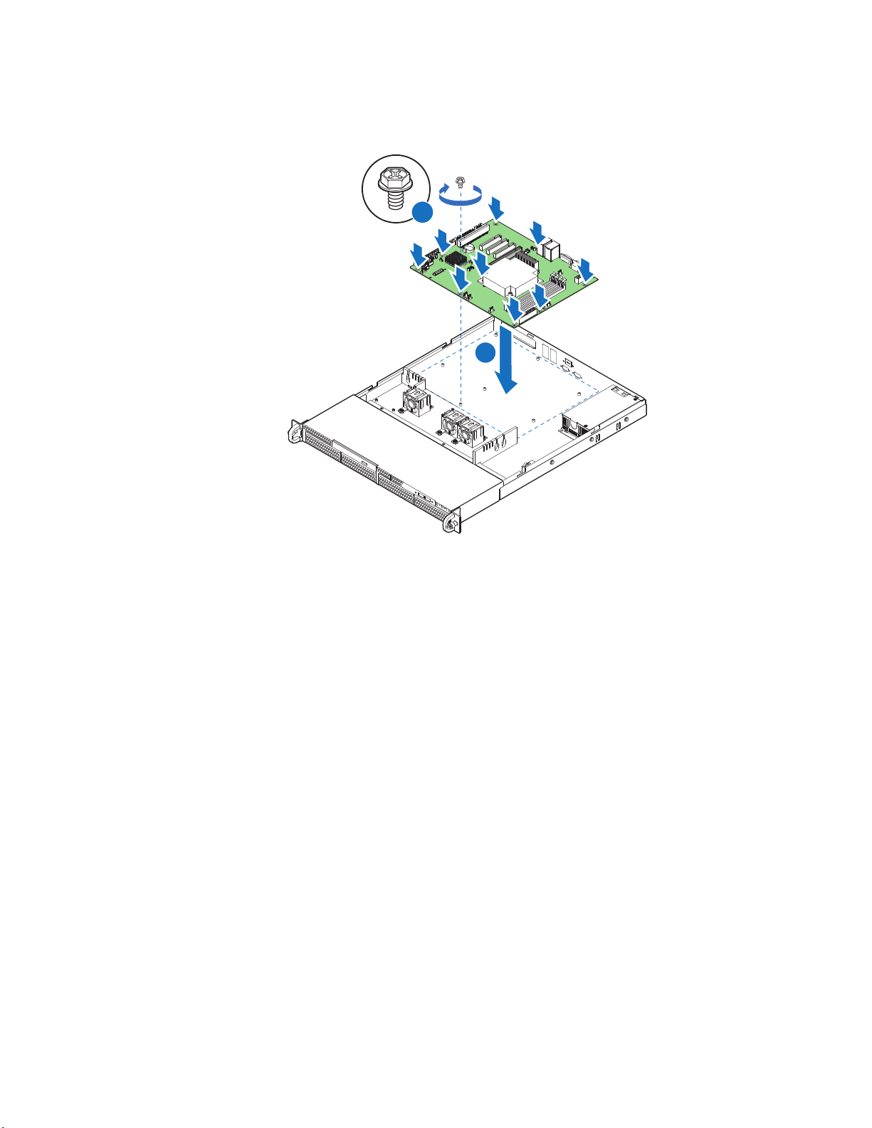
AF003738
A
B
Figure 36. Installing the Server Board
8. Install the processor and the heat sink. For instructions, see “Installing the
Processor” on page 36.
9. Install the system memory. For instructions, see “Installing DIMMs” on page 33.
10. Connect the data cables. For data cable routing information, see .
11. Connect the power cables. For power cable routing information, see “Cable
Routing” on page 69.
12. Install the PCIe* Riser assembly. For instructions, see “Installing the PCIe* Riser
Assembly” on page 52.
13. Install the processor air duct. For instructions, see “Installing the Processor Air
Duct” on page 31.
14. Install the server system cover. For instructions, see “Installing the Server System
Cover” on page 29.
15. Plug all peripheral devices and the AC power cable into the server.
60 Intel® Server System R1304BTSSFAN/R1304BTLSFAN/R1304BTLSHBN Service Guide
Page 81

Replacing the CMOS Battery
Caution: The CMOS battery is NOT hot-swappable. Before removing or replacing the CMOS
battery, you must first take the server out of service, turn off all peripheral devices
connected to the system, turn off the system by pressing the power button, and unplug the
AC power cord from the system or wall outlet.
The lithium battery on the server board powers the RTC in the absence of power. When
the battery starts to weaken, it loses voltage, and the server settings stored in CMOS RAM
in the RTC (for example, the date and time) may be wrong. For a list of approved devices,
contact your customer service representative or dealer.
Warning: Danger of explosion if battery is incorrectly replaced. Replace only with the same or
equivalent type recommended by the equipment manufacturer. Discard used batteries
according to manufacturer's instructions.
Advarsel: Lithiumbatteri - Eksplosionsfare ved fejlagtig håndtering. Udskiftning må kun ske med
batteri af samme fabrikat og type. Levér det brugte batteri tilbage til leverandøren.
Advarsel: Lithiumbatteri - Eksplosjonsfare. Ved utskifting benyttes kun batteri som anbefalt av
apparatfabrikanten. Brukt batteri returneres apparatleverandøren.
Va r ni ng : Explosionsfara vid felaktigt batteribyte. Använd samma batterityp eller en ekvivalent typ
som rekommenderas av apparattillverkaren. Kassera använt batteri enligt fabrikantens
instruktion.
Varoitus: Paristo voi räjähtää, jos se on virheellisesti asennettu. Vaihda paristo ainoastaan
laitevalmistajan suosittelemaan tyyppiin. Hävitä käytetty paristo valmistajan ohjeiden
mukaisesti.
1. Observe the safety and ESD precautions at the beginning of this book. See “Safety
Information” on page iii.
2. Power down the server and unplug all peripheral devices and the AC power cable.
3. Remove the server system cover. For instructions, see “Removing the Server
System Cover” on page 28.
4. Remove the server's cover and locate the battery. See Figure 37.
5. Pull back gently on the metal tab at the top of the battery.
6. Remove the battery from its socket.
Intel® Server System R1304BTSSFAN/R1304BTLSFAN/R1304BTLSHBN Service Guide 61
Page 82

AF003525
Figure 37. Replacing the CMOS Battery
7. Dispose of the battery according to local ordinance.
8. Remove the new lithium battery from its package, and, being careful to observe the
correct polarity, insert it in the battery socket.
9. Close the chassis.
10. Run the BIOS Setup utility to restore the configuration settings.
62 Intel® Server System R1304BTSSFAN/R1304BTLSFAN/R1304BTLSHBN Service Guide
Page 83

Power Supply
1
3
AF003735
2
Replacing the Power Supply
Caution: The power supply is NOT hot-swappable. Before removing or replacing the power supply,
you must first take the server out of service, turn off all peripheral devices connected to
the system, turn off the system by pressing the power button, and unplug the AC power
cord from the system or wall outlet.
You can replace the power supply if it fails or if one of the integrated fans in it fails. To
replace the power supply, use the following instructions.
1. Observe the safety and ESD precautions at the beginning of this book. See “Safety
Information” on page iii.
2. Power down the server and unplug all peripheral devices and the AC power cable.
3. Remove the server system cover. For instructions, see “Removing the Server
System Cover” on page 28.
4. Disconnect all power cables connected to the server board and peripherals.
5. Remove the screws secured the power supply.
6. Lift up the power supply from the chassis.
Figure 38. Removing Power Supply
7. Insert the replacement power supply into the server.
8. Secure the screw you removed in Step 5 to attach the power supply to the
server system.
9. Connect the power supply cables to the server board and peripherals. See Figure 38.
10. Install the server system cover. For instructions, see “Installing the Server System
Cover” on page 29.
11. Plug all peripheral devices and the AC power cable into the server.
Intel® Server System R1304BTSSFAN/R1304BTLSFAN/R1304BTLSHBN Service Guide 63
Page 84

AF003568
Replacing a System Fan
Caution: The fans are NOT hot-swappable. Before removing or replacing a fan, you must first take
the server out of service, turn off all peripheral devices connected to the system, turn off
the system by pressing the power button, and unplug the AC power cord from the system
or wall outlet.
Note: You cannot replace the fans integrated into the power supply separately. If one of the fans
in the power supply fails, you must replace the power supply.
If one of the fans fails, you can individually replace them. If a fan in the power supply
fails, you must replace the power supply. Use the following steps to replace a system fan
or the CPU cooling fan.
Replacing the System Fans
1. See “Safety Information” on page iii.
2. Power down the server and unplug all peripheral devices and the AC power cable.
3. Remove the server system cover. For instructions, see “Removing the Server
System Cover” on page 28.
4. Remove the processor air duct. For instructions, see “Removing the Processor Air
Duct” on page 30.
5. Disconnect the fan cables from the server board.
6. Lift the fan holder from the server.
Figure 39. Removing Bracket and System Fans from Server System.
64 Intel® Server System R1304BTSSFAN/R1304BTLSFAN/R1304BTLSHBN Service Guide
Page 85

7. Lift the fan from the fan-holder.
8. Install the replacement fan.
9. Set the fan assembly into the system. Use caution to make sure you do not pinch
any cables.
10. Route the cable from the fan at the right around the right side of the assembly and
under the clip at the front of the fan bracket.
11. Connect the fans to the server board.
12. Install the processor air duct. For instructions. see “Installing the Processor Air
Duct” on page 31.
Intel® Server System R1304BTSSFAN/R1304BTLSFAN/R1304BTLSHBN Service Guide 65
Page 86

AF003729
Installing and Removing the Rack Handles
Installing the Rack Handles
1. Observe the safety and ESD precautions at the beginning of this book. See “Safety
Information” on page iii.
2. Power down the server and unplug all peripheral devices and the AC power cable.
3. If it is installed, remove the front bezel if it is installed.
4. Attach the rack handle to the server system with two screws as shown in Figure 40.
Figure 40. Installing the Rack Handle
5. Repeat Step 4 on the opposite side of the server.
6. (Optional) Install the front bezel, if desired.
7. Plug all peripheral devices and the AC power cable into the server.
66 Intel® Server System R1304BTSSFAN/R1304BTLSFAN/R1304BTLSHBN Service Guide
Page 87

Removing the Rack Handles
1. Observe the safety and ESD precautions at the beginning of this book. See “Safety
Information” on page iii.
2. Power down the server and unplug all peripheral devices and the AC power cable.
3. If it is installed, remove the front bezel.
4. Remove the two screws holding the rack handle in place, and remove the rack
handle from the server system.
5. Repeat Step 4 on the opposite side of the system.
6. (Optional) Install the front bezel, if desired.
7. Plug all peripheral devices and the AC power cable into the server.
Intel® Server System R1304BTSSFAN/R1304BTLSFAN/R1304BTLSHBN Service Guide 67
Page 88

68 Intel® Server System R1304BTSSFAN/R1304BTLSFAN/R1304BTLSHBN Service Guide
Page 89

Appendix A: Technical Reference
Cable Routing
When you add or remove components from your server system, make sure your cables are
routed correctly before reinstalling the server system cover. Use caution to make sure no
cables or wires are pinched and that the airflow from the fans is not blocked. Use the
following figures to determine the correct cable routing.
For readability, separate figures for power ca
included. Make sure all necessary power and data cables are connected and routed as
shown. Dashed lines in the drawings indicate a location where a cable is routed beneath a
component and each connector end is labeled with the same letter. For example, the PCI
cooling fan cable is labeled with the letter “C” both where it connects to the server board
and at the PCI cooling fan itself.
ble routing and data cable routing are
Intel® Server System R1304BTSSFAN/R1304BTLSFAN/R1304BTLSHBN Service Guide 69
Page 90
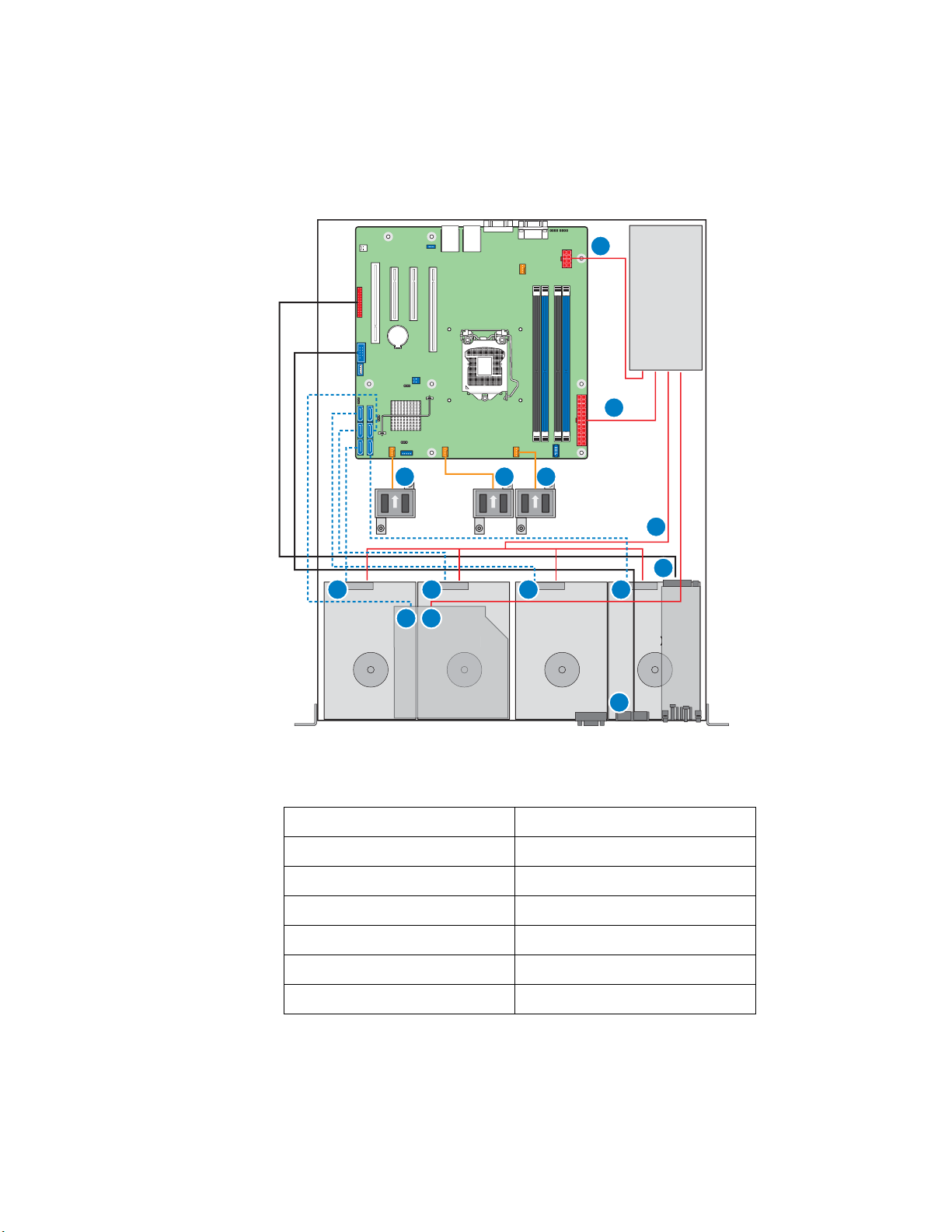
AF003909
HDD 0 HDD 1 HDD 2 HDD 3
Optical Device
3
A
N
G H I
J
K
C
L M
D E F
B
Cable Routing (R1304BTSSFAN)
A. Internal USB to Front H. System FAN2
B. Front Panel I. System FAN3
C. SATA port to HSBP HDD0 J. Power Supply to Main Power
D. SATA port to HSBP HDD1 K. Power Supply to CPU Power
E. SATA port to HSBP HDD2 L. ODD to SATA Port
F. SATA port to HSBP HDD3 M. Power Supply to ODD
G. System FAN1 N. Power Supply to HDDs
Figure 41. Cable Routing (R1304BTSSFAN)
70 Intel® Server System R1304BTSSFAN/R1304BTLSFAN/R1304BTLSHBN Service Guide
Page 91

AF003910
DIMM A2
DIMM A1
DIMM B2
DIMM B1
CPU
HDD 0 HDD 1 HDD 2 HDD 3
HDD 1
Optical Device
3
A
B
O
G
H I
J
K
L
C
M N
D E F
Cable Routing (R1304BTLSFAN)
A. Internal USB to Front I. System FAN3
B. Front Panel J. Power Supply to Main Power
C. SATA port to HSBP HDD0 K. Power Supply to P/S AUX
D. SATA port to HSBP HDD1 L. Power Supply to CPU Power
E. SATA port to HSBP HDD2 M. ODD to SATA Port
F. SATA port to HSBP HDD3 N. Power Supply to ODD
G. System FAN1 O. Power Supply to HDDs
H. System FAN2
Figure 42. Cable Routing (R1304BTLSFAN)
Intel® Server System R1304BTSSFAN/R1304BTLSFAN/R1304BTLSHBN Service Guide 71
Page 92
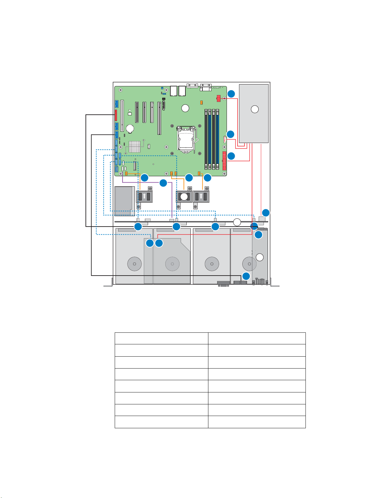
AF003730
DIMM A2
DIMM A1
DIMM B2
DIMM B1
CPU
HDD 0 HDD 1 HDD 2 HDD 3
HDD 1
Optical Device
3
BBU
A
B
C
D
E
E
F
K
C
B
A
G
DL
H I J
M
N O P
Cable Routing (R1304BTLSHBN)
A. Power Supply to CPU Power I. SATA port to HSBP HDD1
B. Power Supply to P/S AUX J. SATA port to HSBP HDD2
C. Power Supply to Main Power K. SATA port to HSBP HDD3
D. Power Supply to ODD L. ODD to SATA Port
E. Power Supply to HDDs M. SGPIO
F. Internal USB to Front N. System FAN1
G. Front Panel O. System FAN2
H. SATA port to HSBP HDD0 P. System FAN3
Figure 43. Cable Routing (R1304BTLSHBN)
72 Intel® Server System R1304BTSSFAN/R1304BTLSFAN/R1304BTLSHBN Service Guide
Page 93
350-W Single Power Supply Input Voltages
• 100 - 127 V at 50/60 Hz 6.0 A
• 200 - 240 V at 50/60 Hz 3.0 A
350-W Single Power Supply Output Voltages
Table 6 lists the total wattage available from the power subsystem for each voltage. For
information about calculating the power usage for your co
Power Usage.”
Table 6. Power Supply Output Capability
Voltage Maximum Current
+3.3 V 14 A
nfiguration, see “Calculating
+5.0 V 18 A
+5 V Standby 2 A
+12.0 24 A
-12.0 V 0.3 A
Warning: Do not exceed a combined power output of 90 W for the +5 V and +3.3 V outputs.
Exceeding a combined 90 W will overload the power subsystem and may cause the power
supplies to overheat and malfunction.
Intel® Server System R1304BTSSFAN/R1304BTLSFAN/R1304BTLSHBN Service Guide 73
Page 94

System Environmental Specifications
Table 7. System Environmental Specifications
Temperature
Non-operating
Operating
Humidity
Non-operating 90% relative humidity, non-condensing at 35°C
Shock
Operating
Packaged
-40° to 70°C
10° to 35°C, with the maximum rate of change not to exceed 10°C per hour
2.0 g, 11 msec, 1/2 sine
Operational after an 24-inch free fall.
Acoustic noise 7 Bels in sound power for a typical office ambient temperature
Electrostatic
discharge (ESD)
(65 to 75 °F). Your selection of peripherals may change the noise level.
Tested to 8 Kilovotls (KV) contact discharge, 12 kilovolts (KV) air discharge;
no component damage.
74 Intel® Server System R1304BTSSFAN/R1304BTLSFAN/R1304BTLSHBN Service Guide
Page 95

Appendix B: Troubleshooting
This chapter helps you identify and solve problems that might occur while you are using
the system.
For any issue, first ensure you are using the latest firmware
include updates for the BIOS, Baseboard Management Controller (BMC), and hot-swap
controller (HSC). See “Server System References” on page xi for a link to the software
updates. In addition to the server firmware and files, also
components you installed in your system, such as video drivers, network drivers, and
SATA drivers.
Intel provides a package called the “Platform Confid
diagnostics. See “Server System References” on page xi for a link to this software.
If you cannot resolve your server problems on your own, see “Getting Help” on page 89
for assistance.
Resetting the System
Before going through in-depth troubleshooting, attempt first to reset your system using
one of the methods below.
Table 8. Resetting the System
To do this Press
Soft boot reset to clear the system memory and
reload the operating system
and files. Firmware upgrades
update any drivers used for
ence Test” that may help with your
<Ctrl+Alt+Del>
Clear system memory, restart POST, and reload the
operating
Cold boot reset. Turn the system
on. This clears system memory, restarts POST,
reloads the operating system, and halts power to all
peripherals
Reset the BMC and get it back to a stable state Remove AC power from
Intel® Server System R1304BTSSFAN/R1304BTLSFAN/R1304BTLSHBN Service Guide 75
system
power off and then
Reset button
Power off/on button
the
server for one minute
Page 96

Problems following Initial System Installation
Problems that occur at initial system startup are usually caused by an incorrect installation
or configuration. Hardware failure is a less frequent cause. If the problem you are
experiencing is with a specific software application, see
Application Software” on page 82.
First Steps Checklist
• Is AC power available at the wall outlet?
• Are the power supplies plugged in? Check the AC cable(s) on the back of the chassis
and at the AC source.
• Are all cables correctly connected and secured?
• Are the processors fully seated in their sockets on the server board?
• Are all standoffs in the proper location and not touching any components, causing a
potential short?
“Problems with Newly Installed
• Are all add-in PCI boards fully seated in their slots on the server board?
• Are all jumper settings on the server board correct?
• Are all jumper and switch settings on add-in boards and peripheral devices correct?
To check these settings, refer to the manufacturer's documentation that comes with
them. If applicable, ensure there are no conflicts (for example, two add-in boards
sharing the same interrupt).
• Are all peripheral devices installed correctly?
• If the system has a hard disk drive, is it properly formatted or configured?
• Are all device drivers properly installed?
• Are the configuration settings made in Setup correct?
• Is the operating system properly loaded? See the operating system documentation.
• Did you press the system power on/off switch on the front panel to turn the server on
(power on light should be lit)?
• Is the system power cord properly connected to the system and plugged into a
NEMA 5 15R outlet for 100-120 V or a NEMA 6-15R outlet for 200-240 V?
• Are all integrated components from the tested components lists? Check the tested
memory and chassis lists, as well as the supported hardware and operating system
list. See “Server System References” on page xi for links to the tested
component lists.
76 Intel® Server System R1304BTSSFAN/R1304BTLSFAN/R1304BTLSHBN Service Guide
Page 97

Hardware Diagnostic Testing
This section provides a more detailed approach to identifying a hardware problem and
locating its source.
Caution: Turn off devices before disconnecting cables: Before disconnecting any peripheral cables
from the system, turn off the system and any external peripheral devices. Failure to do so
can cause permanent damage to the system and/or the peripheral devices.
1. Turn off the system and all external peripheral devices. Except for the keyboard and
video monitor, disconnect each device from the system.
2. Make sure the system power cord is plugged into a properly grounded AC outlet.
3. Make sure your video display monitor and keyboard are correctly connected to the
system. Turn on the video monitor. Set its brightness and contrast controls to at
least two thirds of their maximum ranges (see the documentation supplied with
your video display monitor).
4. If the operating system normally loads from the hard disk drive, make sure there is
no CD-ROM/DVD disk in the optical drive.
5. If the power LED does light, attempt to boot from a USB floppy or from a CDROM disk.
6. Turn on the system. If the power LED does not light, see “Power Light Does Not
Light” on page 78.
Verifying Proper Operation of Key System Lights
As POST determines the system configuration, it tests for the presence of each mass
storage device installed in the system. As each device is checked, its activity light should
turn on briefly. Check for the following:
• Does the drive activity light turn on briefly? If not, see “Drive Activity Light Does
Not Light” on page 80.
Confirming Loading of the Operating System
Once the system boots up, the operating system prompt displays on the screen. The
prompt varies according to the operating system. If the operating system prompt does not
display, see
“No Characters Appear on Screen” on page 78.
Specific Problems and Corrective Actions
This section provides possible solutions for these specific problems:
• Power light does not light.
• No characters appear on screen.
Intel® Server System R1304BTSSFAN/R1304BTLSFAN/R1304BTLSHBN Service Guide 77
Page 98

• Characters on the screen appear distorted or incorrect.
• System cooling fans do not rotate.
• Diskette drive activity light does not light.
• Hard disk drive activity light does not light.
• CD-ROM drive activity light does not light.
• There are problems with application software.
• The bootable CD-ROM is not detected.
Try the following solutions in the order given. If you cannot correct the problem, contact
your service representative or authorized dealer for help.
Power Light Does Not Light
Check the following:
• Did you press the power-on button?
• Is the system operating normally? If yes, the power LED might be defective or the
connection from the front panel to the server board might be loose.
• Have you securely plugged the server AC power cord into the power supply?
• Some ATX power supplies have a power switch on the back of the power supply. If
your system has one, is it turned on?
• Remove all add-in cards and see if the system boots. If successful, add the cards
back in one at a time with a reboot between each addition.
• Make sure the memory DIMMs comply with the system requirements.
• Make sure the memory DIMMs have been populated according to the system
requirements.
• Remove the memory DIMMs and re-seat them.
• Make sure the processor(s) comply with the system requirements.
• Make sure the processor(s) have been populated according to the system
requirements.
• Remove the processor(s) and re-seat them.
• Make sure the chassis standoffs are installed only below mounting holes. Misplaced
standoffs can contact the pins on the bottom of the server board and cause a short.
No Characters Appear on Screen
Check the following:
• Is the keyboard functioning? Test it by turning the “Num Lock” function on and off
to make sure the Num Lock light is functioning.
78 Intel® Server System R1304BTSSFAN/R1304BTLSFAN/R1304BTLSHBN Service Guide
Page 99

• Is the video monitor plugged in and turned on? If you are using a switch box, is it
switched to the correct system?
• Are the brightness and contrast controls on the video monitor properly adjusted?
• Is the video monitor signal cable properly installed?
• Does this video monitor work correctly if plugged into a different system?
• Is the onboard video controller enabled in the BIOS?
• Remove all add-in cards and see if the video returns. If successful, add the cards
back in one at a time with a reboot between each addition.
• Make sure the memory DIMMs comply with the system requirements.
• Make sure the memory DIMMs have been populated according to the system
requirements.
• Remove the memory DIMMs and re-seat them.
• Make sure the processor(s) comply with the system requirements.
• Make sure the processor(s) have been populated according to the system
requirements.
• Remove the processor(s) and re-seat them.
If you are using an add-in video controller board, do the following:
1. Verify the video works using the onboard video controller.
2. Verify the video controller board is fully seated in the server board connector.
3. Reboot the system for changes to take effect.
4. If there are still no characters on the screen after you reboot the system and POST
emits a beep code, write down the beep code you hear. This information is useful
for your service representative.
5. If you do not receive a beep code and characters do not display, the video display
monitor or video controller may have failed. Contact your service representative or
authorized dealer for help.
Characters Are Distorted or Incorrect
Check the following:
• Are the brightness and contrast controls properly adjusted on the video monitor? See
the manufacturer's documentation.
• Are the video monitor's signal and power cables properly installed?
• Does this video monitor work correctly if plugged into a different system?
System Cooling Fans Do Not Rotate Properly
If the system cooling fans are not operating properly, it is an indication of possible system
component failure.
Intel® Server System R1304BTSSFAN/R1304BTLSFAN/R1304BTLSHBN Service Guide 79
Page 100

Check the following:
• Is the power-on light lit? If not, see “Power Light Does Not Light” on page 78.
• Are any other front panel LEDs lit?
• Have any of the fan motors stopped? Use the server management subsystem to
check the fan status.
• Have your fans speeded up in response to an overheating situation?
• Have your fans speeded up in response to a fan that has failed?
• Are the fan power connectors properly connected to the server board?
• Is the cable from the front panel board connected to the both the front panel board
and to the server board?
• Are the power supply cables properly connected to the server board?
• Are there any shorted wires caused by pinched-cables or have power connector
plugs been forced into power connector sockets the wrong way?
Drive Activity Light Does Not Light
Check the following:
• Are the drive's power and signal cables properly installed?
• Are all relevant switches and jumpers on the drive set correctly?
• Is the drive properly configured?
• Is the drive activity light always on? If so, the signal cable may be plugged
in incorrectly.
CD-ROM Drive or DVD-ROM Drive Activity Light Does Not Light
Check the following:
• Are the CD-ROM/DVD-ROM drive's power and signal cables properly installed?
• Are all relevant switches and jumpers on the drive set correctly?
• Is the drive properly configured?
Cannot Connect to a Server
• Make sure the network cable is securely attached to the correct connector at the
system back panel.
• Try a different network cable.
• Make sure you are using the correct and the current drivers. See “Server System
References” on page xi for a link to the current drivers.
80 Intel® Server System R1304BTSSFAN/R1304BTLSFAN/R1304BTLSHBN Service Guide
 Loading...