

Page 1

Intel® Server System R1000SPO
Revision 1.0
March 2016
Intel® Server Boards and Systems
Product Family
Technical Product Specification
A document providing an overview of product features, functions, architecture, and
support specifications
Page 2

Intel® Server System R1000SPO Product Family TPS
Date
Revision Number
Modifications
January 2016
0.7
First preliminary version
March 2016
1.0
First External Public Release
Changes:
Updated Illustrations
Appendix E - Added High Temperature Ambient Information
Section 3.3.4 - Added Holdup time for Fixed Power Supply
Section 3.2.3 - Added Information for Power Distribution Board
Added Glossary
Removed – AXXPRAIL from supported Rail kits
Updated Copyright data
Table 2 - Added info about PCIe riser slot
Revision History
i
Page 3

Intel® Server System R1000SPO Product Family TPS
Disclaimers
No license (express or implied, by estoppel or otherwise) to any intellectual property rights is granted by this
document.
Intel disclaims all express and implied warranties, including without limitation, the implied warranties of
merchantability, fitness for a particular purpose, and non-infringement, as well as any warranty arising from
course of performance, course of dealing, or usage in trade.
This document contains information on products, services and/or processes in development. All information
provided here is subject to change without notice. Contact your Intel representative to obtain the latest TPS.
The products and services described may contain defects or errors known as errata which may cause
deviations from published specifications. Current characterized errata are available on request.
Intel, and the Intel logo are trademarks of Intel Corporation in the U.S. and/or other countries.
*Other names and brands may be claimed as the property of others
© 2016 Intel Corporation.
ii
Page 4

Intel® Server System R1000SPO Product Family TPS
Table of Contents
1. Introduction ........................................................................................................................................ 1
1.1 Chapter Outline .................................................................................................................................... 1
1.2 Server Board Use Disclaimer ......................................................................................................... 2
1.3 Product Errata ....................................................................................................................................... 2
2. Product Family Overview ................................................................................................................ 3
2.1 Operating System Support............................................................................................................... 5
2.1.1 OS Validation Levels .......................................................................................................................... 5
2.1.2 OS Technical Support Levels ......................................................................................................... 6
2.2 System Features Overview.............................................................................................................. 6
2.3 Server Board Features Overview .................................................................................................. 8
2.4 Back Panel Features ....................................................................................................................... 10
2.5 Front Control Panel .......................................................................................................................... 11
2.6 Front Drive Bay Options ................................................................................................................. 11
2.7 Locking Front Bezel ......................................................................................................................... 12
2.8 System Dimensions ......................................................................................................................... 14
2.8.1 Chassis Dimensions ........................................................................................................................ 14
2.8.2 Label Emboss Dimensions ........................................................................................................... 15
2.8.3 Pull-out Tab Label Emboss Dimensions ................................................................................. 16
2.9 Available Rack Mounting Kit Options ....................................................................................... 16
2.10 System Level Environmental Limits .......................................................................................... 17
2.11 System Packaging ............................................................................................................................ 18
2.11.1 Intel Product Weight Information ................................................................................................ 18
3. System Power ................................................................................................................................. 19
3.1 Power Supply Configurations ...................................................................................................... 19
3.2 Power Supply Module Options .................................................................................................... 20
3.2.1 Power Supply Module Efficiency ................................................................................................ 20
3.2.2 Power Supply Module Mechanical Overview ........................................................................ 20
3.2.3 Power distribution board ................................................................................................................ 21
3.2.4 Power Cord Specification Requirements ................................................................................ 22
3.3 AC Power Supply Input Specifications ..................................................................................... 22
3.3.1 Power Factor ...................................................................................................................................... 22
3.3.2 AC Input Voltage Specification .................................................................................................... 23
3.3.3 AC Line Isolation Requirements ................................................................................................. 23
3.3.4 AC Line Dropout / Holdup ............................................................................................................. 23
3.3.5 AC Line Fuse ...................................................................................................................................... 24
3.3.6 AC Line Transient Specification .................................................................................................. 24
3.3.7 Susceptibility Requirements ......................................................................................................... 25
3.3.8 Electrostatic Discharge Susceptibility ....................................................................................... 25
3.3.9 Fast Transient/Burst ........................................................................................................................ 25
3.3.10 Radiated Immunity ........................................................................................................................... 25
iii
Page 5

Intel® Server System R1000SPO Product Family TPS
3.3.11 Power Recovery ................................................................................................................................ 25
3.3.12 Voltage Interruptions ....................................................................................................................... 25
3.3.13 Protection Circuits ............................................................................................................................ 25
3.3.14 Power Supply Status LED ............................................................................................................. 27
3.4 Server Board Power Connectors................................................................................................ 27
4. Thermal Management ................................................................................................................... 29
4.1 Thermal Operation and Configuration Requirements ........................................................ 30
4.2 Thermal Management Overview ................................................................................................ 30
4.2.1 Fan Speed Control ........................................................................................................................... 30
4.2.2 Programmable Fan PWM Offset ................................................................................................ 31
4.2.3 Fan Domains ...................................................................................................................................... 31
4.2.4 Nominal Fan Speed ......................................................................................................................... 32
4.2.5 Thermal and Acoustic Management ......................................................................................... 32
4.2.6 Thermal Sensor Input to Fan Speed Control ......................................................................... 32
4.3 System Fans ....................................................................................................................................... 34
5. System Storage and Peripheral Drive Bay Overview ........................................................... 36
5.1 Front Mount Drive Support............................................................................................................ 36
5.2 System Fan RVI and Hard Disk Drive Storage Performance ......................................... 36
5.3 Hot Swap Drive Carriers ................................................................................................................ 37
5.4 Storage Backplane Options .......................................................................................................... 39
5.4.1 I2C Functionality ............................................................................................................................... 40
5.4.2 4 x 3.5” Drive Hot-Swap Backplane Overview ...................................................................... 40
5.4.3 8 x 2.5” Drive SAS Backplane ..................................................................................................... 42
5.5 M.2 SSD Support .............................................................................................................................. 43
5.6 SATA DOM Support ........................................................................................................................ 44
6. Storage Controller Options Overview ...................................................................................... 45
6.1 Embedded SATA/SATA RAID Support ................................................................................... 45
6.2 Intel® Integrated RAID Module Support ................................................................................... 47
6.2.1 Intel® RAID Maintenance Free Backup Unit (RMFBU) Support .................................... 47
7. Front Control Panel and I/O Panel Overview .......................................................................... 48
7.1 I/O Panel Features ........................................................................................................................... 48
7.2 Control Panel Features .................................................................................................................. 48
7.2.1 System Status LED .......................................................................................................................... 49
8. PCIe* Riser Card Support ............................................................................................................ 51
9. Intel® I/O Module Support ........................................................................................................... 52
10. Basic and Advanced Server Management Features ............................................................ 53
10.1 IPMI 2.0 Features ............................................................................................................................. 54
10.2 Non-IPMI Features ........................................................................................................................... 54
10.2.1 Dedicated Management Port ....................................................................................................... 55
10.2.2 Embedded Web Server .................................................................................................................. 55
10.2.3 Advanced Management Feature Support (RMM4 Lite) .................................................... 57
Appendix A: Integration and Usage Tips ........................................................................................ 61
iv
Page 6

Intel® Server System R1000SPO Product Family TPS
Appendix B: POST Code Diagnostic LED Decoder ..................................................................... 62
Appendix C: POST Code Errors ........................................................................................................ 72
Appendix D: System Cable Routing Diagrams ............................................................................. 76
Appendix E: High Temperature Ambient Info ................................................................................ 77
Glossary .................................................................................................................................................. 79
v
Page 7

Intel® Server System R1000SPO Product Family TPS
List of Figures
Figure 1. System Components Overview ............................................................................................................. 6
Figure 2. Top Cover Features .................................................................................................................................... 7
Figure 3. Server Board Features ............................................................................................................................... 8
Figure 4. On-board Diagnostic LEDs ...................................................................................................................... 9
Figure 5. System Reset and Configuration Jumpers .................................................................................... 10
Figure 6. Back Panel Features ................................................................................................................................ 10
Figure 7. Front Control Panel Options ............................................................................................................... 11
Figure 8. 3.5" Drive Bay – 4 Drive Configuration (Model R1304SPxxxxx) ............................................ 11
Figure 9. 2.5" Drive Bay – 8 Drive Configuration (Model R1208SPxxxxx) ............................................ 11
Figure 10. Front Bezel ............................................................................................................................................... 12
Figure 11. Front Bezel Accessory with Optionally Installed Wave Feature ........................................ 12
Figure 12. Front Bezel Accessory with Optionally Installed Wave and ID Badge (1) ...................... 13
Figure 13. Front Bezel Accessory with Optionally Installed Wave and ID Badge (2) ...................... 13
Figure 14. Front Bezel Accessory ID Badge Mechanical Drawings ......................................................... 13
Figure 15. Chassis Dimensions .............................................................................................................................. 14
Figure 16. Label Emboss Dimensions ................................................................................................................. 15
Figure 17. Pull-out Tab Label Emboss Dimensions ...................................................................................... 16
Figure 18. 350W AC Fixed Power Supply ......................................................................................................... 19
Figure 19. 450W AC Power Supply...................................................................................................................... 19
Figure 20. 350W Power Supply Mechanical Drawings ................................................................................ 20
Figure 21. 450W Power Supply Mechanical drawings ................................................................................ 21
Figure 22. Power Distribution Board ................................................................................................................... 21
Figure 23. AC Power Cord ........................................................................................................................................ 22
Figure 24. System Air Flow and Fan Identification ........................................................................................ 29
Figure 25. Fan Control Model ................................................................................................................................ 33
Figure 26. System Fans ............................................................................................................................................. 34
Figure 27. System Fan Connector Locations on Server Board ................................................................ 35
Figure 28. 8x2.5" Drive Bay Configuration (Model R1208xxxxx) ............................................................. 36
Figure 29. 4x3.5" Drive Bay Configuration (Model R1304WTxxxx) ........................................................ 36
Figure 30. Hot Swap Storage Device Carrier Removal ................................................................................. 37
Figure 31. 2.5" SSD mounted to 3.5" Drive Tray ............................................................................................ 38
Figure 32. Drive Tray LED Identification ............................................................................................................ 38
Figure 33. Backplane Installation ......................................................................................................................... 40
Figure 34. 4 x 3.5” Drive Hot-Swap Backplane – front view ...................................................................... 41
Figure 35. 4 x 3.5” Drive Hot-Swap Backplane – rear view ........................................................................ 41
Figure 36. 8 x 2.5” Drive SAS/SATA Backplane – front view ..................................................................... 42
Figure 37. 8 x 2.5” Drive SAS/SATA Backplane – rear view ....................................................................... 42
Figure 38. Installing M.2 Device ............................................................................................................................ 43
Figure 39. Intel® Raid Upgrade Key ...................................................................................................................... 46
Figure 40. Intel® RAID Maintenance Free Backup Unit ................................................................................. 47
vi
Page 8

Intel® Server System R1000SPO Product Family TPS
Figure 41. Front I/O Panel Features .................................................................................................................... 48
Figure 42. Front Panel LEDs and Buttons ......................................................................................................... 48
Figure 43. Add-in Card Support ............................................................................................................................ 51
Figure 44. Riser Card Assembly............................................................................................................................. 51
Figure 45. Intel® I/O Module Placement ............................................................................................................ 52
Figure 46. Intel® RMM4 Lite Activation Key Installation .............................................................................. 55
Figure 47. POST Diagnostic LED Location ........................................................................................................ 62
Figure 48. Internal Cable Routing ......................................................................................................................... 76
vii
Page 9

Intel® Server System R1000SPO Product Family TPS
List of Tables
Table 1. Reference Documents ................................................................................................................................ 1
Table 2. Intel® Server System R1000SPO Product Family Feature Set ................................................... 3
Table 3. Operating System Support List .............................................................................................................. 5
Table 4. Operating System Validation Levels .................................................................................................... 5
Table 5. System Environmental Limits Summary .......................................................................................... 17
Table 6. Intel Product Weight Information ....................................................................................................... 18
Table 7. 350 Watt AC Power Supply Efficiency (Gold) ................................................................................ 20
Table 8. 450 Watt AC Power Supply Efficiency (Gold) ................................................................................ 20
Table 9. AC Power Cord Specifications .............................................................................................................. 22
Table 10. Input Voltage Range – 350W Power Supply ............................................................................... 23
Table 11. AC Input Voltage Range – 450W Power Supply ........................................................................ 23
Table 12. AC Line Holdup Time – 350W Power supply .............................................................................. 23
Table 13. AC Line Holdup Time – 450W Power Supply.............................................................................. 24
Table 14. AC Line Sag Transient Performance – 350W Power Supply ................................................ 24
Table 15. AC Line Surge Transient Performance – 350W Power Supply ............................................ 24
Table 16. AC Line Sag Transient Performance – 450W Power Supply ................................................ 24
Table 17. AC Line Surge Transient Performance – 450W Power Supply ............................................ 25
Table 18. Performance Criteria ............................................................................................................................. 25
Table 19. Over Current Protection – 350W Power Supply ........................................................................ 26
Table 20. Over Current Protection – 450 Watt Power Supply ................................................................. 26
Table 21. Over Voltage Protection - 350W Power Supply ........................................................................ 26
Table 22. Over Voltage Protection (OVP) Limits – 750W Power Supply ............................................. 27
Table 23. LED Indicators .......................................................................................................................................... 27
Table 24. Main Power Connector Pin-out ......................................................................................................... 28
Table 25. CPU Power Connector Pin-out .......................................................................................................... 28
Table 26. PMBUS SSI Connector Pin-out (PS_AUX) ..................................................................................... 28
Table 27. System Volumetric Air Flow ............................................................................................................... 29
Table 28. System Fan Connector Pin-out ......................................................................................................... 35
Table 29. Drive Status LED States ........................................................................................................................ 39
Table 30. Drive Activity LED States ...................................................................................................................... 39
Table 31. SATA/SATADOM capable Connector Pin-out ............................................................................ 44
Table 32. Front Control Panel Buttons And Indicators ............................................................................... 48
Table 33. System Status LED Indicator States ................................................................................................ 49
Table 34. Front panel LED indication of BMC state ...................................................................................... 50
Table 35. Supported Intel® I/O Modules ........................................................................................................... 52
Table 36. Intel® Remote Management Module 4 (RMM4) Options ......................................................... 53
Table 37. Basic and Advanced Server Management Features Overview ............................................. 53
Table 38. POST Progress Code LED Example ................................................................................................. 63
viii
Page 10

Intel® Server System R1000SPO Product Family TPS
Table 39. POST Progress Codes ........................................................................................................................... 63
Table 40. MRC Progress Codes ............................................................................................................................. 69
Table 41. POST Progress LED Codes .................................................................................................................. 70
Table 42. POST Error Codes and Messages..................................................................................................... 72
Table 43. POST Error Beep Codes ....................................................................................................................... 74
Table 44. Integrated BMC Beep Codes .............................................................................................................. 75
ix
Page 11

Page 12

Intel® Server System R1000SPO Product Family TPS
Document Title
Document
Classification
Intel® Server Board S1200SP Family BMC EPS 1.1
Intel Confidential
Intel® Server Board S1200SP Family BIOS EPS v1.0
Intel Confidential
Intel® Xeon® Processor E3-1200 v5 Product Family
Datasheet
Intel Confidential
Intel® Ethernet Controller I210: Datasheet
Intel® Server Board S1200SP Family Technical Product
Specification 1.0
1. Introduction
This Technical Product Specification (TPS) provides system level information for the Intel® Server System
R1000SPO product family.
This document describes the embedded functionality and available features of the integrated server system
which includes: the chassis layout, system boards, power subsystem, cooling subsystem, storage subsystem
options, and available installable options. Note that some system features are provided as configurable
options and may not be included standard in every system configuration offered. Please reference the Intel®
Server Board S1200SP Product Family Configuration Guide for a list of configurable options.
Server board specific detail can be obtained by referencing the Intel® Server Board S1200SP Technical
Product Specification.
NOTE: Some of the documents listed in the following table are classified as “Intel Confidential”. These
documents are made available under a Non-Disclosure Agreement (NDA) with Intel and must be ordered
through your local Intel representative.
Table 1. Reference Documents
1.1 Chapter Outline
This document is divided into the following chapters:
Chapter 1 – Introduction
Chapter 2 – Product Family Overview
Chapter 3 – System Power
Chapter 4 – Thermal Management
Chapter 5 – System Storage and Peripherals Drive Bay Overview
Chapter 6 – Storage Controller Options Overview
Chapter 7 – Front Control Panel and I/O Panel Overview
Chapter 8 – PCIe* Riser Card Support
Chapter 9 – Intel® I/O Module Support
Chapter 10 – Basic and Advanced Server Management Features
Appendix A – Integration and Usage Tips
Appendix B – POST Code Diagnostic LED Decoder
Appendix C – POST Code Errors
Appendix D – System Configuration Tables for Thermal Compatibility
Appendix E – High Temperature Ambient Info
Glossary
1
Page 13

Intel® Server System R1000SPO Product Family TPS
1.2 Server Board Use Disclaimer
Intel Corporation server boards support add-in peripherals and contain a number of high-density VLSI and
power delivery components that need adequate airflow to cool. Intel ensures through its own chassis
development and testing that when Intel® server building blocks are used together, the fully integrated
system will meet the intended thermal requirements of these components. It is the responsibility of the
system integrator who chooses not to use Intel-developed server building blocks to consult vendor
datasheets and operating parameters to determine the amount of airflow required for their specific
application and environmental conditions. Intel Corporation cannot be held responsible if components fail
or the server board does not operate correctly when used outside any of their published operating or nonoperating limits.
1.3 Product Errata
Shipping product may have features or functionality that may deviate from published specifications. These
deviations are generally discovered after the product has gone into formal production. Intel terms these
deviations as product Errata. Known product Errata will be published in the Monthly Specification Update for
the given product family which can be downloaded from the following Intel web site:
http://www.intel.com/support
2
Page 14

Intel® Server System R1000SPO Product Family TPS
Feature
Description
Chassis Type
1U Rack Mount Chassis
Server Board
Intel® Server Board S1200SP – (Intel product code - S1200SPO)
Processor Support
One LGA1151 (Socket H4) processor socket
Support for one Intel® Xeon® E3-1200 V5 processor without processor graphics (GT0 or 4+0)
Maximum supported Thermal Design Power (TDP) of up to 80 W.
8 GT/s point-to-point DMI 3.0 interface to PCH
Memory
Two memory channels, four memory DIMM Slots (Two memory DIMMs per channel)
Support for 2133 MT/s Unbuffered DIMMs (UDIMM DDR4 ECC memory)
Chipset
Intel® C236 Platform Controller Hub (PCH) chipset
External I/O
connections
1x DB-15 video connector
Two Gigabit Ethernet Ports
Dedicated RJ-45 server management port
Two USB 2.0 connectors on back panel
Two USB 3.0 connectors on back panel
Two USB 3.0 connectors on front panel
Internal I/O connectors
/ headers
One Type-A USB 2.0 connector
One 2x5 pin connector providing front panel support for two USB 2.0 ports
One 2x10 pin connector providing front panel support for two USB 2.0 / 3.0 ports
Intel® I/O Module
Accessory Options
The server board includes a proprietary on-board connector allowing for the installation of a variety of
available Intel® I/O modules. An installed I/O module can be supported in addition to standard on-board
features and add-in PCIe* cards.
The Following Intel® I/O Modules are supported:
AXX4P1GBPWLIOM – Quad port 1GbE I/O based on Intel® Ethernet Controller I350
AXX10GBNIAIOM – Dual SFP+ port 10GbE based on Intel® 82599 10 Gigabit Ethernet Controller
AXX10GBTWLIOM3 – Dual RJ-45 port 10G BASE-T based on Intel® Ethernet Controller X540
System Fans
Three managed 40mm single rotor system fans
One power supply fan for each installed power supply module
Riser Card Support
One x16 PCIe* 3.0 Riser Card H87808-XXX on a x8 Riser slot (slot-6)
Video
Integrated 2D video controller
16 MB DDR3 Memory
2. Product Family Overview
The Intel® Server System R1000SPO product family offers a variety of system options to meet the varied
configuration requirements of entry level computing environments, and includes several available 1U rack
mount server systems. Each integrated system within this product family is configured around the Intel®
Server Board S1200SPO.
This chapter provides a high-level overview of the system features and available options as supported in
different system models within this product family. Greater detail for each major sub-system, feature, or
option is provided in the following chapters.
Table 2. Intel
®
Server System R1000SPO Product Family Feature Set
3
Page 15

Intel® Server System R1000SPO Product Family TPS
Feature
Description
On-board storage
controllers and options
8x SATA connectors up to 6Gbps
1x SATADOM connector (SATA port 4)
1x 75 pin connector for M.2 SATA SSD (2242 form factor)
Embedded Software SATA RAID
o Intel® RSTe 4 SW RAID through onboard SATA connectors provides SATA RAID 0/1/10/5.
o Intel
®
Embedded Server RAID Technology II through onboard SATA connectors provides SATA
RAID 0/1/10 and optional RAID 5 support provided by the Intel® RAID Activation Key
RKSATA8R5.
Security
Intel® Trusted Platform Module (TPM) 1.2 based on LPC
Server Management
Integrated Baseboard Management Controller, IPMI 2.0 compliant
Support for Intel® Server Management Software
On-board RJ45 management port
Advanced Server Management via an Intel® Remote Management Module 4 Lite (Accessory Option)
Power Supply Options
The server system supports two options for Power Supply:
o 1 x 350w Power Supply (Fixed)
o 2 x 450w Power Supply Modules (Redundant, Hot-Swap capable)
Storage Bay Options
Hot Swap Backplane Options:
NOTE: All available backplane options have support for SAS 3.0 (12 Gb/sec)
4 x 3.5” SAS/SATA backplane
8 x 2.5” SAS/SATA backplane
Storage Bay Options:
4 x 3.5” SAS/SATA hot swap drive bays + front panel I/O
8 x 2.5” SAS/SATA hot swap drive bays + front panel I/O
Supported Rack Mount
Kit Accessory Options
AXXVPSRAIL - Value Plus Short Rail
4
Page 16

Intel® Server System R1000SPO Product Family TPS
Operating System
Operating System
Validation Level
(P)
Windows Server 2012* R2 with Hyper-Vx64 & EFI
P1
Red Hat Enterprise Linux* 7.0 with KVM x64 & UEFI
P1
SuSE Linux Enterprise Server* 12 with XEN x64
P1
Red Hat Enterprise Linux 6U5 with KVM x64 & UEFI
P2
VMWare ESXi* 5.5 U3
P2
SuSE Linux Enterprise Server 11 SP4 with XEN x64
P2
Windows Server 2008 R2 SP1
P2
Windows 7*
P2
Ubuntu* 14.04
P2
FreeBSD* 10.1
P3
CentOS* 7.0
P3
Operating System Validation Levels
P1
P2
P3
Basic Installation testing
Yes
Yes
Yes
Test all on-board I/O features in all modes
Yes
Adapter\Peripheral Compatibility & Stress testing
Yes
Technical Support Level
T1
T2
T3
2.1 Operating System Support
As of this writing, the Intel® Server System R1000SPO product family provides support for the following
operating systems. This list will be updated as new operating systems are validated by Intel.
Table 3. Operating System Support List
Table 4. Operating System Validation Levels
See the following sections for additional information regarding validation levels and technical support levels
as referenced in Table 4.
2.1.1 OS Validation Levels
Basic installation testing is performed with each supported operating system. The testing validates that the
system can install the operating system and that the base hardware feature set is functional. A small set of
peripherals is used for installation purposes only. Add-in adapter cards are not tested.
Adapter compatibility validation (CV) testing uses test suites to gain an accurate view of how the server
performs with a wide variety of adapters under the primary supported operating systems. These tests are
designed to show hardware compatibility between the cards and the server platform and include functional
testing only. No heavy stressing of the systems or the cards is performed for CV testing.
5
Page 17
Intel® Server System R1000SPO Product Family TPS
Stress Testing uses configurations that include add-in adapters in all available slots for a 48-hour (two-day),
or a 72-hour (three-day) test run without injecting errors. Each configuration passes an installation test and a
Network/Disk Stress test. Any fatal errors that occur require a complete test restart.
2.1.2 OS Technical Support Levels
T1: Intel will provide support for issues involving the installation and/or functionality of a specified operating
system as configured with or without supported adapters and/or peripherals.
T2: Intel will provide and test operating system drivers for each of the server board’s integrated controllers,
provided that the controller vendor has a driver available upon request. Vendors will not be required by Intel
to develop drivers for operating systems that they do not already support. Intel will NOT provide support for
issues related to the use of any add-in adapters or peripherals installed in the server system when an
operating system that received only basic installation testing is in use.
T3: Intel will not provide technical support for an open source operating system. All questions and issues
related to an open source operating system must be submitted to and supported by the open source
community supporting the given operating system.
2.2 System Features Overview
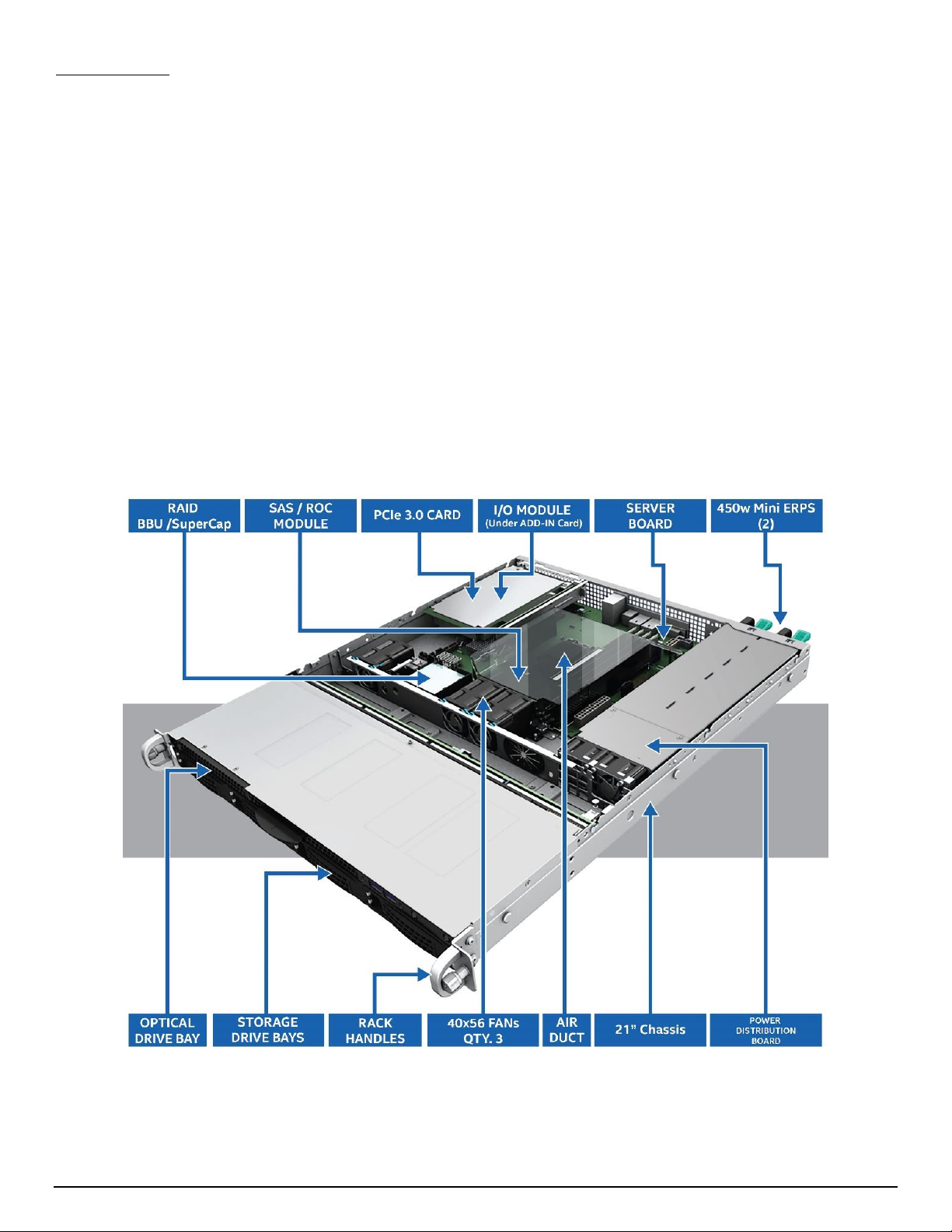
Figure 1. System Components Overview
6
Page 18
Intel® Server System R1000SPO Product Family TPS
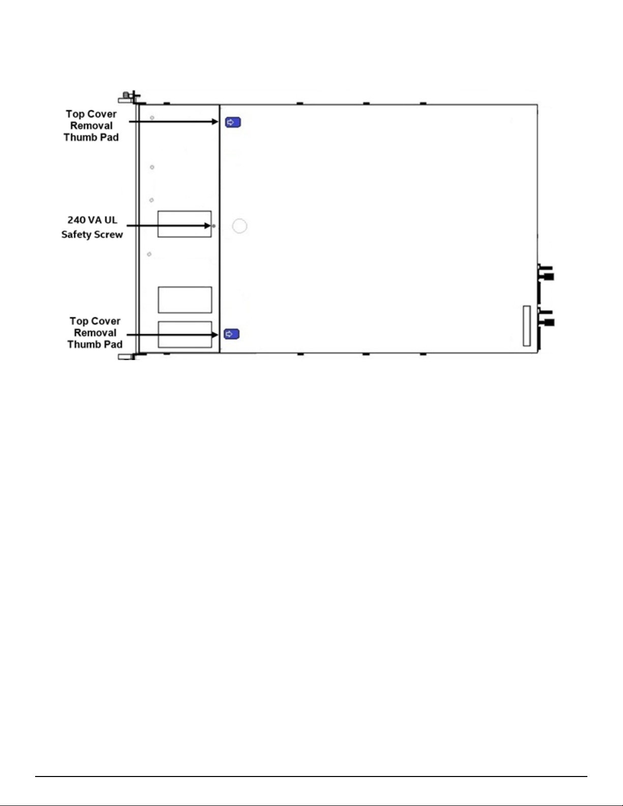
Figure 2. Top Cover Features
7
Page 19
Intel® Server System R1000SPO Product Family TPS
2.3 Server Board Features Overview
The following illustration provides a general overview of the server board, identifying key feature and
component locations. Please refer to Intel® Server Board S1200SP Technical Product Specification for more
information.
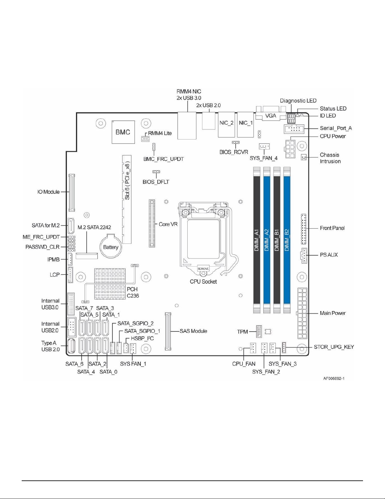
Figure 3. Server Board Features
8
Page 20

Intel® Server System R1000SPO Product Family TPS
The server board includes several LEDs to identify system status. The following illustrations define
supported LEDs and identify their location.
Figure 4. On-board Diagnostic LEDs
9
Page 21
Intel® Server System R1000SPO Product Family TPS
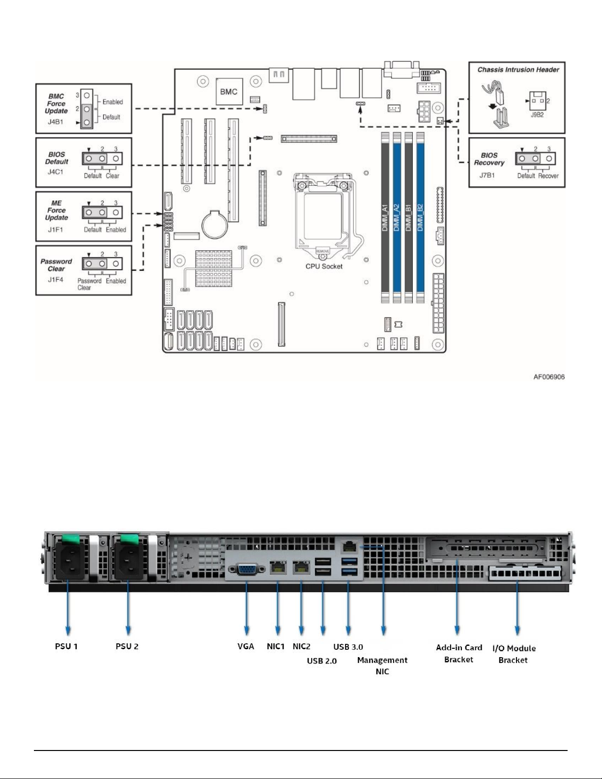
Figure 5. System Reset and Configuration Jumpers
2.4 Back Panel Features
Figure 6. Back Panel Features
10
Page 22
Intel® Server System R1000SPO Product Family TPS
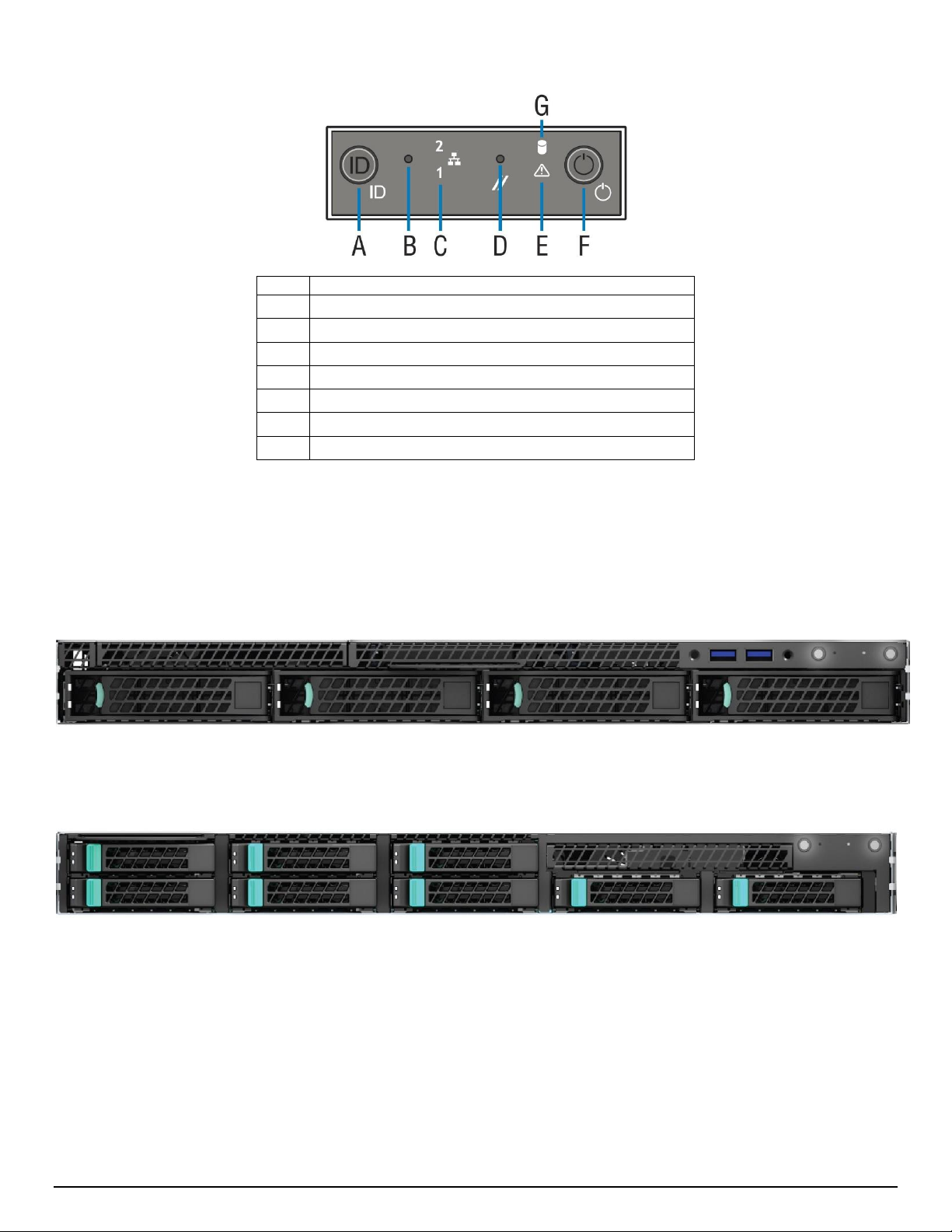
Label
Description
A
System ID Button w/Integrated LED
B
NMI Button (recessed, tool required for use)
C
NIC 1 & 2 Activity LEDs
D
System Cold Reset Button (recessed, tool required for use)
E
System Status LED
F
Power Button w/Integrated LED
G
Drive Activity LED
2.5 Front Control Panel
Figure 7. Front Control Panel Options
2.6 Front Drive Bay Options
Figure 8. 3.5" Drive Bay – 4 Drive Configuration (Model R1304SPxxxxx)
Figure 9. 2.5" Drive Bay – 8 Drive Configuration (Model R1208SPxxxxx)
11
Page 23
Intel® Server System R1000SPO Product Family TPS
2.7 Locking Front Bezel
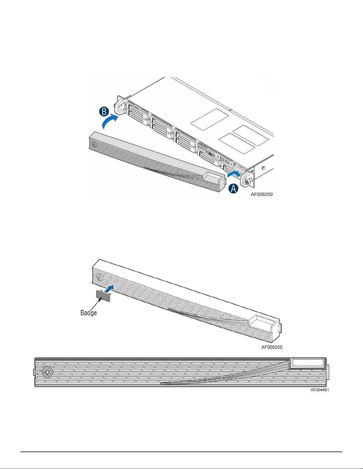
The optional front bezel is made of Black molded plastic and uses a snap-on design. When installed, its
design allows for maximum airflow to maintain system cooling requirements. The front bezel includes a
keyed locking mechanism which can be used to prevent unauthorized access to installed storage devices
and front I/O ports.
Figure 10. Front Bezel
(Intel Product Order Code – A1UBEZEL)
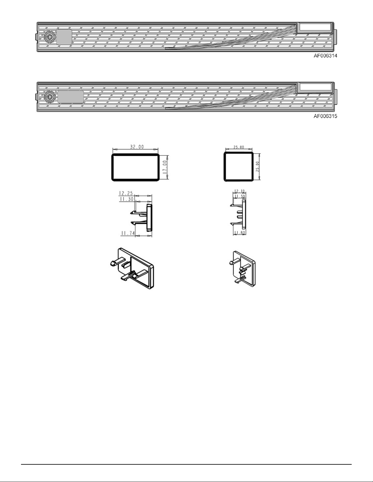
The face of the bezel assembly includes snap-in identification badge options and a wave feature option to
allow for customization.
Figure 11. Front Bezel Accessory with Optionally Installed Wave Feature
12
Page 24
Intel® Server System R1000SPO Product Family TPS
Figure 12. Front Bezel Accessory with Optionally Installed Wave and ID Badge (1)
Figure 13. Front Bezel Accessory with Optionally Installed Wave and ID Badge (2)
Figure 14. Front Bezel Accessory ID Badge Mechanical Drawings
13
Page 25
Intel® Server System R1000SPO Product Family TPS
1.7”
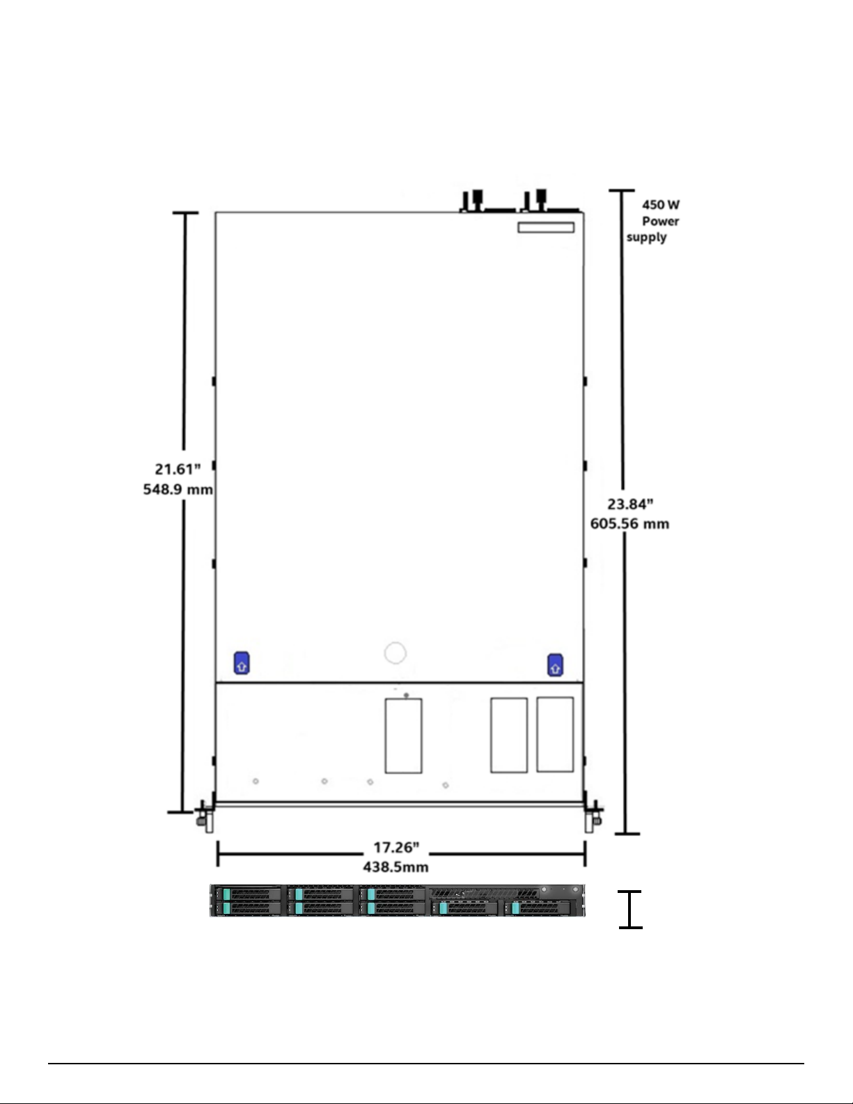
2.8 System Dimensions
2.8.1 Chassis Dimensions
Figure 15. Chassis Dimensions
14
Page 26
Intel® Server System R1000SPO Product Family TPS
2.8.2 Label Emboss Dimensions
15
Figure 16. Label Emboss Dimensions
Page 27

Intel® Server System R1000SPO Product Family TPS
2.8.3 Pull-out Tab Label Emboss Dimensions
Figure 17. Pull-out Tab Label Emboss Dimensions
2.9 Available Rack Mounting Kit Options
Advisory Note – Available rack and cabinet mounting kits are not designed to support shipment of the
server system while installed in a rack. If you chose to do so, Intel advises you verify your shipping
configuration with appropriate shock and vibration testing, before shipment. Intel does not perform shipping
tests which cover the complex combination of unique rack offerings and custom packaging options.
Caution: Exceeding the rail kit’s specified maximum weight limit or misalignment of the server in the rack
may result in failure of the rack rails, resulting in damage to the system or personal injury. Two people or the
use of a mechanical assist tool to install and align the server into the rack is highly recommended.
Available Rack mounting kits:
AXXVPSRAIL – Vale plus short rail
- 424mm max travel length
- 129 lbs. (59 Kg) max support weight
- Front and rear mounting bracket adjustment distance: 609mm to 705mm
- Stab-in system install
- x8 #10-32 screws to mount rail kit on rack flange (screw kit come with rail kit assembling)
- No cable management arm support
16
Page 28
Intel® Server System R1000SPO Product Family TPS
Parameter
Limits
Temperature
Operating
ASHRAE Class A2 – Continuous Operation. 10º C to 35º C (50º F to 95º F) with the maximum
rate of change not to exceed 10°C per hour
ASHARE Class A3 – Includes operation up to 40°C for up to 900 hours per year. Refer to
Appendix E for detailed guidance.
Shipping
-40º C to 70º C (-40º F to 158º F)
Altitude
Operating
Support operation up to 3050m with ASHRAE class de-ratings.
Humidity
Shipping
50% to 90%, non-condensing with a maximum wet bulb of 28° C (at temperatures from 25°
C to 35° C)
Shock
Operating
Half sine, 2 g, 11 mSec
Unpackaged
Trapezoidal, 25 g, velocity change is based on packaged weight
Packaged
ISTA (International Safe Transit Association) Test Procedure 3A 2008
Vibration
Unpackaged
5 Hz to 500 Hz 2.20 g RMS random
Packaged
ISTA (International Safe Transit Association) Test Procedure 3A 2008
AC-DC
Voltage
90 V to 132 V and 180 V to 264 V
Frequency
47 Hz to 63 Hz
Source Interrupt
No loss of data for power line drop-out of 12 mSec
Surge Nonoperating and
operating
Unidirectional
Line to earth Only
AC Leads 2.0 kV
I/O Leads 1.0 kV
DC Leads 0.5 kV
ESD
Air Discharged
12.0 kV
Contact Discharge
8.0 kV
Acoustics
Sound Power
Measured
Power in Watts
<300 W ≥300 W ≥600 W ≥1000 W
Servers/Rack
Mount Sound
Power Level (in
BA)
7.0 7.0 7.0 7.0
2.10 System Level Environmental Limits
The following table defines the system level operating and non-operating environmental limits.
Table 5. System Environmental Limits Summary
17
Page 29

Intel® Server System R1000SPO Product Family TPS
Product code
Net Weight(kg)
Gross Weight(kg)
Net Weight (Lbs.)
Gross Weight (Lbs.)
R1304SPOSHBN
7.77
11.6
17.1
25.6
R1304SPOSHOR
8.87
12.8
19.6
28.2
R1208SPOSHOR
9.09
13
20
28.7
E1304SPOSHON
8.99
12.8
19.8
28.2
2.11 System Packaging
The original Intel packaging, in which the server system is delivered, is designed to provide protection to a
fully configured system and was tested to meet ISTA (International Safe Transit Association) Test Procedure
3A (2008). The packaging was also designed to be re-used for shipment after system integration has been
completed.
The original packaging includes – a small inner box for ship along accessories, the outer shipping main box,
and various protective inner packaging components. The boxes and packaging components are designed to
function together as a protective packaging system. When reused, all of the original packaging material must
be used, including both boxes and each inner packaging component. In addition, all inner packaging
components MUST be reinstalled in the proper location to ensure adequate protection of the system for
subsequent shipment.
Please refer to the Intel® Server System R1000SPO Product Family System Integration and Service Guide for
complete packaging assembly instructions.
NOTE: The design of the inner packaging components does not prevent improper placement within the
packaging assembly. There is only one correct packaging assembly that will allow the package to meet the
ISTA (International Safe Transit Association) Test Procedure 3A (2008) limits.
Failure to follow the specified packaging assembly instructions may result in damage to the system during
shipment.
2.11.1 Intel Product Weight Information
Table 6. Intel Product Weight Information
NOTE: An L6 system does not include processors, memory, drives, or add-in cards. It is the system
configuration as shipped from Intel. Integrated system weights (System configurations that include the items
above) will vary depending on the final system configuration. For the 1U product family, a fully integrated
un-packaged system can weigh up to 40 Lbs. (18+ Kg).
18
Page 30

Intel® Server System R1000SPO Product Family TPS
3. System Power
This chapter provides a high level overview of the features and functions related to system power.
3.1 Power Supply Configurations
Systems within this product family are offered with options to support a single fixed mount 350 watt power
supply or dual 450 watt power supply modules. Dual power supply configurations support the following
power configurations: 1+0 (single), and 1+1 (redundant).
1+1 redundant power is supported if the total system power draw remains below the maximum power
capacity of a single power supply module. If a power supply fails, the remaining power supply will allow the
system to remain fully operational. The power supplies are hot swap capable allowing the failed power
supply to be replaced without powering down the system.
In dual power supply configured systems, the power supplies are modular, allowing for tool-less insertion
and extraction from a bay in the back of the chassis. When inserted, the card edge connector of the power
supply mates blindly to a matching slot connector on the Power Distribution Board (PDB).
19
Figure 18. 350W AC Fixed Power Supply
Figure 19. 450W AC Power Supply
Page 31

Intel® Server System R1000SPO Product Family TPS
Loading
Efficiency
20% of maximum
85%
50% of maximum
88%
100% of maximum
85%
Loading
Efficiency
20% of maximum
88%
50% of maximum
92%
100% of maximum
88%
3.2 Power Supply Module Options
There are two power supply options available for this server product family: 350W AC (fixed mount) and
450W AC (Module).
3.2.1 Power Supply Module Efficiency
The following tables provide the required minimum efficiency level at various loading conditions. These are
provided at three different load levels: 100%, 50%, and 20%.
The AC power supply efficiency is tested over an AC input voltage of 230 VAC.
Table 7. 350 Watt AC Power Supply Efficiency (Gold)
Table 8. 450 Watt AC Power Supply Efficiency (Gold)
3.2.2 Power Supply Module Mechanical Overview
Figure 20. 350W Power Supply Mechanical Drawings
20
Page 32

Intel® Server System R1000SPO Product Family TPS
Figure 21. 450W Power Supply Mechanical drawings
3.2.3 Power distribution board
The dual power supply configuration option for the Intel® Server System R1000SPO product family
incorporates a Power Distribution Board (PDB), and is where the Redundant Power Supply modules are
attached. The Connections for Server Board power, communications for power supply monitoring, power for
the Backplane and Optical Disk Drive, come from the Power Distribution Board. For connector pinout and
power supply monitoring details, please refer to the Intel® Server Board S1200SP Product Family Technical
Product Specification. The PDB is designed to plug directly to the output connector of the power supply and
it contains two DC/DC power converters to produce other required voltages.
Figure 22. Power Distribution Board
21
Page 33

Intel® Server System R1000SPO Product Family TPS
Cable Type
SJT
Wire Size
16 AWG
Temperature Rating
105ºC
Amperage Rating
13 A
Voltage Rating
125 V
Output power (350w PSU)
20% load
50% load
100% load
Power factor
0.8
0.9
0.98
Output power (450w PSU)
20% load
50% load
100% load
Power factor
0.8
0.9
0.95
3.2.4 Power Cord Specification Requirements
The AC power cord used must meet the specification requirements listed in the following table.
Table 9. AC Power Cord Specifications
Figure 23. AC Power Cord
3.3 AC Power Supply Input Specifications
The following sections provide the AC Input Specifications for systems configured with AC power supply
modules.
3.3.1 Power Factor
The power supply must meet the power factor requirements stated in the Energy Star* Program
Requirements for Computer Servers. These requirements are stated below.
22
Page 34

Intel® Server System R1000SPO Product Family TPS
PARAMETER
MIN
RATED
MAX
Max Input AC Current
Line Voltage (110)
90V
rms
100-127 V
rms
140V
rms
6 A
rms
1
Line Voltage (220)
180V
rms
200-240 V
rms
264V
rms
3 A
rms
2
Frequency
47 Hz
50/60Hz
63 Hz
DC Voltage
237VDC
250VDC
262VDC
PARAMETER
MIN
RATED
VMAX
Start-up VAC
Power-off VAC
Voltage (110)
90 V
rms
100-127 V
rms
140 V
rms
1
85VAC +/-4VAC
70VAC +/-5VAC
Voltage (220)
180 V
rms
200-240 V
rms
264 V
rms
2
Frequency
47 Hz
50/60 Hz
63 Hz³
Loading
Holdup time
75%
12msec
3.3.2 AC Input Voltage Specification
The power supply must operate within all specified limits over the following input voltage range. Harmonic
distortion of up to 10% of the rated line voltage must not cause the power supply to go out of specified
limits. Application of an input voltage below 85VAC shall not cause damage to the power supply, including a
blown fuse.
Table 10. Input Voltage Range – 350W Power Supply
1. Maximum input current at low input voltage range shall be measured at 90VAC, at max load.
2. Maximum input current at high input voltage range shall be measured at 180VAC, at max load.
Table 11. AC Input Voltage Range – 450W Power Supply
1. Maximum input current at low input voltage range shall be measured at 90VAC, at max load.
2. Maximum input current at high input voltage range shall be measured at 180VAC, at max load.
3. This requirement is not to be used for determining agency input current markings.
3.3.3 AC Line Isolation Requirements
The power supply shall meet all safety agency requirements for dielectric strength. Transformers’ isolation
between primary and secondary windings must comply with the 3000Vac (4242Vdc) dielectric strength
criteria. If the working voltage between primary and secondary dictates a higher dielectric strength test
voltage the highest test voltage should be used. In addition the insulation system must comply with
reinforced insulation per safety standard IEC 950. Separation between the primary and secondary circuits,
and primary to ground circuits, must comply with the IEC 950 spacing requirements.
3.3.4 AC Line Dropout / Holdup
An AC line dropout is defined to be when the AC input drops to 0VAC at any phase of the AC line for any
length of time. An AC line dropout for less than 12ms shall not cause tripping of control signals or protection
circuits. If the AC dropout lasts longer than the holdup time the power supply should recover and meet all
turn on requirements. The power supply shall meet the AC dropout requirement over rated AC voltages and
frequencies. A dropout of the AC line for any duration shall not cause damage to the power supply.
23
Table 12. AC Line Holdup Time – 350W Power supply
Page 35

Intel® Server System R1000SPO Product Family TPS
Loading
Holdup time
75%
12msec
100%
10msec
AC Line Sag (10sec interval between each sagging)
Duration
Sag
Operating AC Voltage
Line Frequency
Performance Criteria
Continuous
10%
Nominal AC Voltage ranges
50/60Hz
No loss of function or performance
1 to 12ms
100%
Nominal AC Voltage ranges
50/60Hz
No loss of function or performance
> 12ms
>30%
Nominal AC Voltage ranges
50/60Hz
Loss of function acceptable, selfrecoverable
AC Line Surge
Duration
Surge
Operating AC Voltage
Line Frequency
Performance Criteria
Continuous
10%
Nominal AC Voltages
50/60Hz
No loss of function or performance
0 to ½ AC
cycle
30%
Nominal AC Voltages
50/60Hz
No loss of function or performance
AC Line Sag (10sec interval between each sagging)
Duration
Sag
Operating AC Voltage
Line Frequency
Performance Criteria
0 to 1/2 AC cycle
95%
Nominal AC Voltage ranges
50/60Hz
No loss of function or performance
> 1 AC cycle
>30%
Nominal AC Voltage ranges
50/60Hz
Loss of function acceptable, self-recoverable
Table 13. AC Line Holdup Time – 450W Power Supply
3.3.5 AC Line Fuse
The power supply shall have one line fused in the single line fuse on the line (Hot) wire of the AC input. The
line fusing shall be acceptable for all safety agency requirements. The input fuse shall be a slow blow type.
AC inrush current shall not cause the AC line fuse to blow under any conditions. All protection circuits in the
power supply shall not cause the AC fuse to blow unless a component in the power supply has failed. This
includes DC output load short conditions.
3.3.6 AC Line Transient Specification
AC line transient conditions shall be defined as “sag” and “surge” conditions. “Sag” conditions are also
commonly referred to as “brownout”, these conditions will be defined as the AC line voltage dropping below
nominal voltage conditions. “Surge” will be defined to refer to conditions when the AC line voltage rises
above nominal voltage.
Table 14. AC Line Sag Transient Performance – 350W Power Supply
Table 15. AC Line Surge Transient Performance – 350W Power Supply
Table 16. AC Line Sag Transient Performance – 450W Power Supply
24
Page 36

Intel® Server System R1000SPO Product Family TPS
AC Line Surge
Duration
Surge
Operating AC Voltage
Line Frequency
Performance Criteria
Continuous
10%
Nominal AC Voltages
50/60Hz
No loss of function or performance
0 to ½ AC cycle
30%
Mid-point of nominal AC Voltages
50/60Hz
No loss of function or performance
Level
Description
A
The apparatus shall continue to operate as intended. No degradation of performance.
B
The apparatus shall continue to operate as intended. No degradation of performance beyond spec limits.
C
Temporary loss of function is allowed provided the function is self-recoverable or can be restored by the
operation of the controls.
Table 17. AC Line Surge Transient Performance – 450W Power Supply
3.3.7 Susceptibility Requirements
The power supply shall meet the following electrical immunity requirements when connected to a cage with
an external EMI filter which meets the criteria defined in the SSI document EPS Power Supply Specification.
For further information on Intel standards please request a copy of the Intel Environmental Standards
Handbook.
Table 18. Performance Criteria
3.3.8 Electrostatic Discharge Susceptibility
The power supply shall comply with the limits defined in EN 55024: 1998/A1: 2001/A2: 2003 using the IEC
61000-4-2: Edition 1.2: 2001-04 test standard and performance criteria B defined in Annex B of CISPR 24.
3.3.9 Fast Transient/Burst
The power supply shall comply with the limits defined in EN55024: 1998/A1: 2001/A2: 2003 using the IEC
61000-4-4: Second edition: 2004-07 test standard and performance criteria B defined in Annex B of CISPR
24.
3.3.10 Radiated Immunity
The power supply shall comply with the limits defined in EN55024: 1998/A1: 2001/A2: 2003 using the IEC
61000-4-3: Edition 2.1: 2002-09 test standard and performance criteria A defined in Annex B of CISPR 24.
3.3.11 Power Recovery
The power supply shall recover automatically after an AC power failure. AC power failure is defined to be
any loss of AC power that exceeds the dropout criteria.
3.3.12 Voltage Interruptions
The power supply shall comply with the limits defined in EN55024: 1998/A1: 2001/A2: 2003 using the IEC
61000-4-11: Second Edition: 2004-03 test standard and performance criteria C defined in Annex B of CISPR
24.
3.3.13 Protection Circuits
Protection circuits inside the power supply cause only the power supply’s main outputs to shut down. If the
power supply latches off due to a protection circuit tripping, an AC cycle OFF for 15 seconds and a PSON#
cycle HIGH for one second reset the power supply.
25
Page 37

Intel® Server System R1000SPO Product Family TPS
Output Voltage
Continuous Load
Current Limit MIN
Current Limit MAX
+12V1
18.2A
20A
+12V2
18.2A
20A
+5V
19.2A
24A
+3.3V
12A
15A
-12V
4A
+5VSB
4.5A
Output
Min OCP
Max OCP
+12V
40 A
54 A
5Vstby
3.6A~8A
Output Voltage
OVP MIN (V)
OVP MAX (V)
+3.3V
3.7
4.5
+5V
5.7
6.5
+12V1/+12V2
13.3
15.6
-12V
-13.3
-15.6
+5VSB
5.7
6.5
3.3.13.1 Over-current Protection (OCP)
The power supply shall have current limit to prevent the outputs from exceeding the values shown in table
below. If the current limits are exceeded the power supply shall shutdown and latch off. The latch will be
cleared by toggling the PSON# signal or by an AC power interruption. The power supply shall not be
damaged from repeated power cycling in this condition. 5VSB will be auto-recovered after removing OCP
limit.
Table 19. Over Current Protection – 350W Power Supply
Table 20. Over Current Protection – 450 Watt Power Supply
3.3.13.2 Over-voltage Protection (OVP)
The power supply over voltage protection shall be locally sensed. The power supply shall shutdown and
latch off after an over voltage condition occurs. This latch shall be cleared by an AC power interruption. The
values are measured at the output of the power supply’s connectors. The voltage shall never exceed the
maximum levels when measured at the power connectors of the power supply connector during any single
point of fail. The voltage shall never trip any lower than the minimum levels when measured at the power
connector. 12VSB will be auto-recovered after removing OVP limit.
Table 21. Over Voltage Protection - 350W Power Supply
26
Page 38

Intel® Server System R1000SPO Product Family TPS
OUTPUT VOLTAGE
PROTECTION POINT [ V]
+12 V
13.6V ~ 15.0V
5VSB
5.6V ~ 6.5V
Power Supply Condition
LED State
Output ON and OK
GREEN
No AC power to all power supplies
OFF
AC present / Only 12VSB on (PS off) or PS in Cold
redundant state
1Hz Blink GREEN
AC cord unplugged or AC power lost; with a second
power supply in parallel still with AC input power.
AMBER
Power supply warning events where the power supply
continues to operate; high temp, high power, high
current, slow fan.
1Hz Blink Amber
Power supply critical event causing a shutdown; failure,
OCP, OVP, Fan Fail
AMBER
Power supply FW updating
2Hz Blink GREEN
Table 22. Over Voltage Protection (OVP) Limits – 750W Power Supply
3.3.13.3 Over-temperature Protection (OTP)
The power supply will be protected against over temperature conditions caused by loss of fan cooling or
excessive ambient temperature. In an OTP condition the PSU will shut down. When the power supply
temperature drops to within specified limits, the power supply shall restore power automatically, while the
12VSB remains always on. The OTP circuit must have built in margin such that the power supply will not
oscillate on and off due to temperature recovering condition. The OTP trip level shall have a minimum of 4C
of ambient temperature margin.
3.3.14 Power Supply Status LED
There is a single bi-color LED to indicate the power supply status on the Redundant Power Supply Modules.
The LED operation is defined in the following table.
Table 23. LED Indicators
3.4 Server Board Power Connectors
The server board provides several connectors to provide power to various system options. The following
sub-sections will provide the pin-out definition; and a brief usage description for each.
The main power supply connection uses an SSI-compliant 2x12 pin connector.
Two additional power-related connectors also exist:
One SSI-compliant 2x4 pin power connector to provide 12-V power to the CPU voltage regulators and
memory.
One SSI-compliant 1x5 pin connector to provide monitoring of the power supply.
27
Page 39

Intel® Server System R1000SPO Product Family TPS
Pin
IO
Signal Name
Pin
IO
Signal Name
1
PWR
+3.3V
13
PWR
+3.3V
2
PWR
+3.3V
14
PWR
-12V (NA for most designs)
3
GND
GND
15
GND
GND
4
PWR
+5V
16
I
PS_ON#
5
GND
GND
17
GND
GND
6
PWR
+5V
18
GND
GND
7
GND
GND
19
GND
GND
8 O PWR_GD
20
NC
NC
9
PWR
SB5V
21
PWR
+5V
10
PWR
+12V
22
PWR
+5V
11
PWR
+12V
23
PWR
+5V
12
PWR
+3.3V
24
GND
GND
Pin
IO
Signal Name
Pin
IO
Signal Name
1
GND
GND
5
PWR
P12V1
2
GND
GND
6
PWR
P12V1
3
GND
GND
7
PWR
P12V2
4
GND
GND
8
PWR
P12V2
Pin
IO
Signal Name
1 I PMBUS_CLK
2
IO
PMBUS_DATA
3 O IRQ_PMBUS_ALERT_N
4
GND
GND Return Sense
5 I P3V3 Sense
The following tables define the pin-out for the connectors:
Table 24. Main Power Connector Pin-out
Table 25. CPU Power Connector Pin-out
Table 26. PMBUS SSI Connector Pin-out (PS_AUX)
28
Page 40

Intel® Server System R1000SPO Product Family TPS
4X3.5'' Front End
All System Fan
PSU Fan
w/o
PSU(CFM)
w/
PSU(CFM)
100%
Auto
42.6
44.19
85%
35.3
37.2
75%
31.1
32.4
65%
26.7
27.6
55%
22.3
22.7
45%
18.1
18.2
35%
13.5
14.0
20%
7.5
7.7
4. Thermal Management
The fully integrated system is designed to operate at external ambient temperatures of between 10°C and
35°C. Working with integrated platform management, several features within the system are designed to
move air in a front to back direction, through the system and over critical components to prevent them from
overheating and allow the system to operate with best performance.
Figure 24. System Air Flow and Fan Identification
The following table provides air flow data associated with one of the system models within this 1U product
family, and is provided for reference purposes only. The data was derived from actual wind tunnel test
methods and measurements using fully configured (worst case) system configurations. Lesser system
configurations may produce slightly different data results. In addition, the CFM data was derived using server
management utilities that utilize platform sensor data, and may vary slightly from the data listed in the
tables.
Table 27. System Volumetric Air Flow
29
Page 41

Intel® Server System R1000SPO Product Family TPS
The Intel® Server System R1000SPO product family is thermally designed and developed in compliance with
ASHRAE Class A2 environment guidance; however, there is extra thermal margin for all components in the
system, so ASHRAE Class A3 environment conditions can be thermally supported.
Note: ASHARE Class A3 – Includes operation up to 40°C for up to 900 hours per year. Refer to Appendix E for
detailed HTA guidance.
The installation and functionality of several system components are used to maintain system thermals. They
include three managed 40mm single rotor system fans, fans integrated into each installed power supply
module, an air duct, populated drive carriers, and a CPU heat sink. Drive carriers can be populated with a
storage device (SSD or Hard Disk Drive) or supplied drive blank.
4.1 Thermal Operation and Configuration Requirements
To keep the system operating within supported maximum thermal limits, the system must meet the
following operating and configuration guidelines:
The system is designed for sustained operation on ambient temperature up to 35°C (ASHRAE Class
A2)
All externally accessed drive bays must be populated. Drive carriers can be populated with a storage
device (SSD or HDD) or supplied drive blank
When the system is operating, the air duct must be installed at all times
The system top cover must be installed at all times when the system is in operation in order to have
proper air flow
4.2 Thermal Management Overview
In order to maintain the necessary airflow within the system, all of the previously listed components need to
be properly installed. For best system performance, the external ambient temperature should remain below
35°C and all system fans (all rotors) should be operational.
NOTE: All system fans are controlled independent of each other. The fan control system may adjust fan
speeds for different fans based on increasing/decreasing temperatures in different thermal zones within the
chassis.
In the event that system temperatures should continue to increase with the system fans operating at their
maximum speed, platform management may begin to throttle bandwidth of either the memory subsystem or
the processors or both, in order to keep components from overheating and keep the system operational.
Throttling of these subsystems will continue until system temperatures are reduced below preprogrammed
limits.
The power supply will be protected against over temperature conditions caused by excessive ambient
temperature. In an over-temperature protection condition, the power supply module will shut down.
4.2.1 Fan Speed Control
The baseboard management controller (BMC) supports monitoring and control of fan speed (RPM). Each fan
is associated with a fan speed sensor that detects fan failure.
30
Page 42

Intel® Server System R1000SPO Product Family TPS
The system fans are divided into fan domains, each of which has a separate fan speed control signal and a
separate configurable fan control policy. A fan domain can have a set of temperature and fan sensors
associated with it. These are used to determine the current fan domain state.
A fan domain has three states:
The sleep and boost states have fixed (but configurable through OEM SDRs) fan speeds associated
with them
o The nominal state has a variable speed determined by the fan domain policy. An OEM SDR
record is used to configure the fan domain policy
The fan domain state is controlled by several factors. They are listed below in order of precedence, high to
low:
Boost
- Associated fan is in a critical state or missing. The SDR describes which fan domains are boosted
in response to a fan failure or removal in each domain. If a fan is removed when the system is in
‘Fans-off’ mode it will not be detected and there will not be any fan boost till system comes out of
‘Fans-off; mode.
- Any associated temperature sensor is in a critical state. The SDR describes which temperature
threshold violations cause fan boost for each fan domain.
- The BMC is in firmware update mode, or the operational firmware is corrupted.
- If any of the above conditions apply, the fans are set to a fixed boost state speed.
Nominal
- A fan domain’s nominal fan speed can be configured as static (fixed value) or controlled by the
state of one or more associated temperature sensors.
4.2.2 Programmable Fan PWM Offset
The system provides a BIOS Setup option to boost the system fan speed by a programmable positive offset
or a “Max” setting. Setting the programmable offset causes the BMC to add the offset to the fan speeds to
which it would otherwise be driving the fans. The Max setting causes the BMC to replace the domain
minimum speed with alternate domain minimums that also are programmable through SDRs.
This capability is offered to provide system administrators the option to manually configure fan speeds in
instances where the fan speed optimized for a given platform may not be sufficient when a high end add-in
adapter is configured into the system. This enables easier usage of the fan speed control to support Intel as
well as third party chassis and better support of ambient temperatures higher than 35°C.
4.2.3 Fan Domains
System fan speeds are controlled through pulse width modulation (PWM) signals, which are driven
separately for each domain by integrated PWM hardware. Fan speed is changed by adjusting the duty cycle,
which is the percentage of time the signal is driven high in each pulse.
The BMC controls the average duty cycle of each PWM signal through direct manipulation of the integrated
PWM control registers.
The same device may drive multiple PWM signals.
31
Page 43

Intel® Server System R1000SPO Product Family TPS
4.2.4 Nominal Fan Speed
A fan domain’s nominal fan speed can be configured as static (fixed value) or controlled by the state of one
or more associated temperature sensors.
OEM SDR records are used to configure which temperature sensors are associated with which fan control
domains and the algorithmic relationship between the temperature and fan speed. Multiple OEM SDRs can
reference or control the same fan control domain; and multiple OEM SDRs can reference the same
temperature sensors.
The PWM duty-cycle value for a domain is computed as a percentage using one or more instances of a
stepwise linear algorithm and a clamp algorithm. The transition from one computed nominal fan speed
(PWM value) to another is ramped over time to minimize audible transitions. The ramp rate is configurable by
means of the OEM SDR.
Multiple stepwise linear and clamp controls can be defined for each fan domain and used simultaneously.
For each domain, the BMC uses the maximum of the domain’s stepwise linear control contributions and the
sum of the domain’s clamp control contributions to compute the domain’s PWM value, except that a
stepwise linear instance can be configured to provide the domain maximum.
Hysteresis can be specified to minimize fan speed oscillation and to smooth fan speed transitions. If a
Tcontrol SDR record does not contain a hysteresis definition, for example, an SDR adhering to a legacy
format, the BMC assumes a hysteresis value of zero.
4.2.5 Thermal and Acoustic Management
This feature refers to enhanced fan management to keep the system optimally cooled while reducing the
amount of noise generated by the system fans. Aggressive acoustics standards might require a trade-off
between fan speed and system performance parameters that contribute to the cooling requirements and
primarily memory bandwidth. The BIOS, BMC, and SDRs work together to provide control over how this
trade-off is determined.
This capability requires the BMC to access temperature sensors on the individual memory DIMMs.
Additionally, closed-loop thermal throttling is only supported with buffered DIMMs.
4.2.6 Thermal Sensor Input to Fan Speed Control
The BMC uses various IPMI sensors as input to the fan speed control. Some of the sensors are IPMI models
of actual physical sensors whereas some are “virtual” sensors whose values are derived from physical
sensors using calculations and/or tabular information.
The following IPMI thermal sensors are used as input to fan speed control:
1, 7, 9
1
2,4
6
5
5
7
Front Panel Temperature Sensor
CPU Margin Sensors
2,4,5
DIMM Thermal Margin Sensors
Exit Air Temperature Sensor
PCH Temperature Sensor
3,5
Add-In Intel SAS Module Temperature Sensors
PSU Thermal Sensor
3, 8
CPU VR Temperature Sensors
DIMM VR Temperature Sensors
BMC Temperature Sensor
3, 6
Global Aggregate Thermal Margin Sensors
32
Page 44

Intel® Server System R1000SPO Product Family TPS
Resulting
Fan Speed
Policy
Events
Sensor
System Behavior
Memory
Settings
Intrusion
Fan Failure
Power Supply
Failure
Other Sensors
(Chipset, Temp,
etc..)
Policy: CLTT,
Acoustic/Performance,
configuration
Front Panel
Processor
Margin
Hot Swap Backplane Temperature Sensors
I/O Module Temperature Sensor (With option installed)
Intel
®
SAS Module (With option installed)
Notes:
1. For fan speed control in Intel chassis
2. Temperature margin from throttling threshold
3. Absolute temperature
4. PECI value or margin value
5. On-die sensor
6. On-board sensor
7. Virtual sensor
8. Available only when PSU has PMBus
9. Calculated estimate
A simple model is shown in the following figure which gives a high level representation of how the fan speed
control structure creates the resulting fan speeds
Auto-Profile
Throttle
33
Figure 25. Fan Control Model
Page 45

Intel® Server System R1000SPO Product Family TPS
4.3 System Fans
Three single rotor 40 x 56mm system fans, and dedicated fans for the installed power supply modules
provide the primary airflow for the system.
The system includes three system fans (see Figure 26). The fans are held in place by fitting them over
mounting pins coming up from the chassis base.
The Fixed Power Supply option of this product family comes with a dedicated fan inside the Power Supply
Module.
The dual Power Supply Option integrates a Power supply Cage with a fixed single rotor 40x56mm fan for
each Power Supply Module. They are responsible for airflow through the power supply module. The fans are
managed by the fan control system. Should a fan fail, the power supply will shut down.
Figure 26. System Fans
System fans are NOT hot-swap capable
Each fan and is designed for tool-less insertion and extraction from the system. For instructions on
fan replacement, please refer to the Intel® Server System R1000SPO System Integration and Service
Guide
Each fan and incorporates vibration dampening features used to minimize fan vibration affects within
the chassis
Fan speed for each fan is controlled by integrated platform management as controlled by the
integrated BMC on the server board. As system thermals fluctuate high and low, the integrated BMC
firmware will increase and decrease the speeds to specific fans to regulate system thermals.
Each fan has a tachometer signal for each rotor that allows the Integrated BMC to monitor their
status.
Each fan has a 4-pin wire harness that connects to a matching connector on the server board.
34
Page 46

Intel® Server System R1000SPO Product Family TPS
Pin
Signal Name
Type
Description
1
Ground
GND
Ground is the power supply ground
2
12V
Power
Power supply 12 V
3
Fan Tach Fan
PWM
In Out
FAN_TACH signal is connected to the BMC to monitor the fan speed
FAN_PWM signal to control fan speed
4
Fan PWM Fan
Tach
Out In
FAN_PWM signal to control fan speed FAN_TACH signal is connected to
the BMC to monitor the fan speed
Figure 27. System Fan Connector Locations on Server Board
Table 28. System Fan Connector Pin-out
35
Page 47

Intel® Server System R1000SPO Product Family TPS
5. System Storage and Peripheral Drive Bay Overview
The Intel® Server System R1000SPO product family has support for a variety of different storage options,
including:
Up to 8 x 2.5” hot swap SAS or SATA drives (hard disk or SSD)
Up to 4 x 3.5” hot swap SAS or SATA hard disk drives or 2.5” SSDs
SATA Slim-line Optical Drive support
SATADOM Support on SATA port 4
Internally mounted Low Profile M.2 Solid State Device (M.2 SSD)
Support for different storage and peripheral options will vary depending on the system model and/or
available accessory options installed. This section will provide an overview of each available option.
5.1 Front Mount Drive Support
The 1U product family provides options to support either 8x2.5” or 4x3.5” front mounted drives. Both
system options provide front panel I/O and front control panel support.
Figure 28. 8x2.5" Drive Bay Configuration (Model R1208xxxxx)
Figure 29. 4x3.5" Drive Bay Configuration (Model R1304WTxxxx)
5.2 System Fan RVI and Hard Disk Drive Storage Performance
Hard disk drive storage technology, which utilizes the latest state-of-the-art track density architectures, are
susceptible to the effects of system fan rotational vibration interference (RVI) within the server system. As
system fan speeds increase to their upper limits (>80% PWM or > 19,320 RPM), hard disk drive performance
can be impacted.
Intel publishes a list of supported hard drives on its Tested Hardware and OS List (THOL). In general, unless
identified in the NOTES column in the THOL, all listed hard drives have been tested to meet Intel
performance targets when the systems fans are operating above 80% PWM and/or the system is operating
at or below the platform ambient thermal limit of 35°C (95°F).
The THOL may also list hard drives that are only recommended for use in non-extreme operating
environments, where the ambient air is at or below 20°C (68°F) and /or the hard drives are installed in
system configurations where the system fans regularly operate below 80% PWM. Hard drives that require
these support criteria for a given system will include an “Environmental Limitation” tag and message in the
THOL “NOTES” column for that device. Using these drives in the more extreme operating environments puts
these devices at higher risk of performance degradation.
36
Page 48

Intel® Server System R1000SPO Product Family TPS
Intel recommends the following general support guidelines for server systems configured with hard drive
storage technology:
Avoid sustained server operation in extreme operating environments. Doing so will cause the system
fans to operate at their upper speed limits and produce higher levels of RVI which could affect hard
drive performance.
NOTE: Solid State Drive (SSD) performance is not impacted by the effects of system fan RVI.
5.3 Hot Swap Drive Carriers
Each SAS/SATA hard disk drive or SSD that interfaces with a backplane is mounted to a hot swap drive
carrier. Drive carriers include a latching mechanism used to assist with drive extraction and drive insertion.
Figure 30. Hot Swap Storage Device Carrier Removal
NOTE: To ensure proper system air flow requirements, all front drive bays must be populated with a drive
carrier. Drive carriers must be installed with either a drive or supplied drive blank.
There are drive carriers to support 2.5” devices and 3.5” devices. To maintain system thermals, all drive bays
must be populated with a drive carrier mounted with a hard disk drive, SSD, or supplied drive blank. Drive
blanks used with the 3.5” drive carrier can also be used to mount a 2.5” SSD into it as shown below.
37
Page 49

Intel® Server System R1000SPO Product Family TPS
Amber Status LED
Green Activity LED
2.5” only drive tray
Amber Status LED
Green Activity LED
2.5” / 3.5” drive tray
Figure 31. 2.5" SSD mounted to 3.5" Drive Tray
NOTE: Due to degraded performance and reliability concerns, the use of the 3.5” drive blank as a 2.5” device
bracket is intended to support SSD type storage devices only. Installing a 2.5” hard disk drive into the 3.5”
drive blank cannot be supported.
Each drive carrier includes separate LED indicators for drive Activity and drive Status. Light pipes integrated
into the drive carrier assembly direct light emitted from LEDs mounted next to each drive connector on the
backplane to the drive carrier faceplate, making them visible from the front of the system.
Figure 32. Drive Tray LED Identification
38
Page 50

Intel® Server System R1000SPO Product Family TPS
Amber
Off
No access and no fault
Solid On
Hard Drive Fault has occurred
Blink
RAID rebuild in progress (1 Hz), Identify (2 Hz)
Green
Condition
Drive Type
Behavior
Power on with no drive activity
SAS
LED stays on
SATA
LED stays off
Power on with drive activity
SAS
LED blinks off when processing a command
SATA
LED blinks on when processing a command
Power on and drive spun down
SAS
LED stays off
SATA
LED stays off
Power on and drive spinning up
SAS
LED blinks
SATA
LED stays off
Table 29. Drive Status LED States
Table 30. Drive Activity LED States
NOTE: The drive activity LED is driven by signals coming from the drive itself. Drive vendors may choose to
operate the activity LED different from what is described in the table above. Should the activity LED on a
given drive type behave differently than what is described, customers should reference the drive vendor
specifications for the specific drive model to determine what the expected drive activity LED operation
should be.
5.4 Storage Backplane Options
The 1U system has support for two backplane options.
For 2.5” drives:
8 x 2.5” drive (SAS/SATA) backplane
For 3.5” drives:
4 x 3.5 SAS/SATA backplane
All available backplane options mount directly to the back of the drive bay as shown in the following
illustration.
39
Page 51

Intel® Server System R1000SPO Product Family TPS
Figure 33. Backplane Installation
NOTE: For details on the istallation/removal of the Backplane, please refer to the Intel® Server System
R1000SPO Product Family System Integration and Service Guide.
All available SAS/SATA compatible backplanes include the following common features:
12 Gb SAS and 6Gb SAS/SATA
29-pin SFF-8680 12 Gb rated drive interface connectors, providing both power and I/O signals to
attached devices
Hot swap support for SAS/SATA devices
I2C interface from a 3-pin connector for device status communication to the BMC over slave SMBus
LEDs to indicate drive activity and status for each attached device
5.4.1 I2C Functionality
The microcontroller has a master/slave I2C connection to the server board BMC. The microcontroller is not
an IPMB compliant device. The BMC will generate SEL events by monitoring registers on the HSBP
microcontroller for DRIVE PRESENCE, FAULT, and RAID REBUILD in progress.
5.4.2 4 x 3.5” Drive Hot-Swap Backplane Overview
Intel Spare Product Code: FXX35HSCAR
The 3.5” drive system SKUs within the product family will ship with a 4x drive backplane capable of
supporting 12 Gb/sec SAS and 6 Gb/sec SAS / SATA drives. Both hard disks and Solid State Drives (SSDs)
can be supported within a common backplane. Each backplane can support either SATA or SAS devices.
However, mixing of SATA and SAS devices within a common hot swap backplane is not supported.
Supported devices are dependent on the type of host bus controller driving the backplane, SATA only or
SAS.
40
Page 52

Intel® Server System R1000SPO Product Family TPS
Label
Description
A
HDD_0
B
HDD_1
C
HDD_2
D
HDD_3
Label
Description
A
Power connector
B
SAS/SATA Ports 0-3 Mini-SAS HD cable connector
C
I2C connector
The front side of the backplane includes 4 x 29-pin drive interface connectors, each capable of supporting
12 Gb SAS or 6 Gb SAS/SATA. The connectors are numbered 0 thru 3. Signals for all four drive connectors
are routed to a single multi-port mini-SAS HD connector on the back side of the backplane.
Figure 34. 4 x 3.5” Drive Hot-Swap Backplane – front view
On the backside of the backplane are several connectors. The following illustration identifies each.
Figure 35. 4 x 3.5” Drive Hot-Swap Backplane – rear view
A – Power Connector – The backplane includes a 2x2 connector supplying power to the backplane. Power is
routed to the backplane via a power cable harness from the Power Supply Modules.
B – Multi-port Mini-SAS Cable Connector – The backplane includes one multi-port mini-SAS cable
connector providing data signals for four SAS/SATA drives on the backplane. A cable can be routed from
matching connectors on the server board or add-in SAS/SATA RAID cards.
C – I2C Cable Connector – The backplane includes a 1x3 cable connector used as a management interface
to the server board.
41
Page 53

Intel® Server System R1000SPO Product Family TPS
Label
Description
A
HDD_0
B
HDD_1
C
HDD_2
D
HDD_3
E
HDD_4
F
HDD_5
G
HDD_6
H
HDD_7
Label
Description
A
Power connector
B
I2C-In cable connector – From Server board
C
SAS/SATA Ports 4-7 Mini-SAS HD cable connector
D
SAS/SATA Ports 0-3 Mini-SAS HD cable connector
5.4.3 8 x 2.5” Drive SAS Backplane
Intel Spare Product Code: F1U8X25S3HSBP
The 2.5” drive system SKU will ship with a 8x drive backplane capable of supporting 12 Gb/sec SAS and 6
Gb/sec SAS / SATA drives. Both hard disks and Solid State Devices (SSDs) can be supported within a
common backplane. Each backplane can support either SATA or SAS devices. However, mixing of SATA and
SAS devices within a common hot swap backplane is not supported. Supported devices are dependent on
the type of host bus controller driving the backplane, SATA only or SAS.
The front side of the backplane includes 8 x 29-pin drive interface connectors, each capable of supporting
12 Gb SAS or 6 Gb SAS/SATA. The connectors are numbered 0 thru 7. Data signals for each set of four drive
connectors (0-3 and 4-7), are routed to separate multi-port mini-SAS HD connectors on the back side of the
backplane.
Figure 36. 8 x 2.5” Drive SAS/SATA Backplane – front view
On the backside of each backplane are several connectors. The following illustration identifies each.
Figure 37. 8 x 2.5” Drive SAS/SATA Backplane – rear view
42
Page 54

Intel® Server System R1000SPO Product Family TPS
PIN
SIGNAL
SIGNAL
PIN
1
GND
P12V
3
2
GND
P12V
4
A – Power Connector – The backplane includes a 2x2 connector supplying power to the backplane. Power is
routed to the backplane via a power cable harness from the Power Supply Modules.
B – I2C Cable Connectors – The backplane includes a 1x3 cable connector used as a management interface
to the server board.
C and D – Multi-port Mini-SAS Cable Connectors – The backplane includes two multi-port mini-SAS cable
connectors, each providing data signals for four SAS/SATA drives on the backplane. Cables can be routed
from matching connectors on the server board or add-in SAS/SATA RAID cards.
5.5 M.2 SSD Support
The system provides support for a SATA M.2 SSD storage device. A 22x42mm 75-pin connector labeled “M.2
SATA” at the left of the battery section of the server board is used to connect this small flash storage device.
In order to use an M.2 device, a SATA cable needs to be connected between any of the SATA connectors
(SATA-0 to SATA-7, recommend SATA-7 for better cable routing) and the SATA connector (black) next to the
jumpers. See illustration below. This cable needs to be purchased separately.
Figure 38. Installing M.2 Device
Visit https://serverconfigurator.intel.com for a list of supported devices.
43
Page 55

Intel® Server System R1000SPO Product Family TPS
Pin
IO
Signal Name
MH1
PWR
GND
1
GND
GND
2 I SATA_TX_P
3 I SATA_TX_N
4
GND
GND
5 O SATA_RX_N
6 O SATA_RX_P
7
PWR
GND
MH2
PWR
P5V (For Apacer* SATADOM)
GND (For SATA)
5.6 SATA DOM Support
The SATA-4 connector on the server board is designed to be compatible with SATADOM devices.
Table 31. SATA/SATADOM capable Connector Pin-out
Visit https://serverconfigurator.intel.com for a list of supported SATA DOM devices.
44
Page 56

Intel® Server System R1000SPO Product Family TPS
6. Storage Controller Options Overview
The server platform supports different embedded and add-in SAS/SATA controller options to provide a
larger number of possible storage configurations. This section will provide an overview of the different
options available.
6.1 Embedded SATA/SATA RAID Support
The Intel® Server System R1000SPO product family provides an embedded SATA host controller that
supports independent DMA operation on up to eight ports and supports data transfer rates of up to 6.0 Gb/s
(600 MB/s). The SATA controller contains two modes of operation – a legacy mode using I/O space, and an
AHCI mode using memory space. Software that uses legacy mode will not have AHCI capabilities. The Intel®
C230 series chipset supports the Serial ATA Specification, Revision 3.0. The Intel® C230 series also supports
several optional sections of the Serial ATA II: Extensions to Serial ATA 1.0 Specification, Revision 1.0 (AHCI
support is required for some elements).
The server board also offers hardware support for Advanced Host Controller Interface (AHCI), a standardized
programming interface for SATA host controllers. Platforms supporting AHCI may take advantage of
performance features such as no master/slave designation for SATA devices—each device is treated as a
master—and hardware assisted native command queuing. AHCI also provides usability enhancements such
as Hot-Plug. AHCI requires appropriate software support (for example, an AHCI driver) and for some features,
hardware support in the SATA device or additional platform hardware.
The Intel® Server System R1000SPO product family includes support for two embedded software RAID
options:
Intel
Intel
®
Embedded Server RAID Technology 2 (ESRT2) based on LSI* MegaRAID SW RAID technology
®
Rapid Storage Technology (RSTe)
Using the <F2> BIOS Setup Utility, accessed during system POST, options are available to enable/disable SW
RAID, and select which embedded software RAID option to use.
6.1.1.1 Intel
®
Rapid Storage Technology Enterprise
The server board provides support for Intel® Rapid Storage Technology enterprise, providing both AHCI (see
above for details on AHCI) and integrated RAID functionality. The industry-leading RAID capability provides
high-performance RAID functionality on up to 8 SATA ports of the server board on the following
configurations:
RAID Level 0 – Non-redundant striping of drive volumes with performance scaling of up to 6 drives,
enabling higher throughput for data intensive applications such as video editing.
Data security is offered through RAID Level 1, which performs mirroring.
RAID Level 10 provides high levels of storage performance with data protection, combining the fault-
tolerance of RAID Level 1 with the performance of RAID Level 0. By striping RAID Level 1 segments,
high I/O rates can be achieved on systems that require both performance and fault-tolerance. RAID
Level 10 requires 4 hard drives, and provides the capacity of two drives.
RAID Level 5 provides highly efficient storage while maintaining fault-tolerance on 3 or more drives.
By striping parity, and rotating it across all disks, fault tolerance of any single drive is achieved while
only consuming 1 drive worth of capacity. That is, a 3 drive RAID 5 has the capacity of 2 drives, or a 4
drive RAID 5 has the capacity of 3 drives. RAID 5 has high read transaction rates, with a medium write
45
Page 57

Intel® Server System R1000SPO Product Family TPS
rate. RAID 5 is well suited for applications that require high amounts of storage while maintaining
fault tolerance.
RSTe RAID support is provided to allow multiple RAID levels to be combined on a single set of hard drives,
such as RAID 0 and RAID 1 on two disks. Other RAID features include hot-spare support, and SMART alerting.
Software components include an Option ROM for pre-boot configuration and boot functionality, a Microsoft
Windows* compatible driver, and a user interface for configuration and management of the RAID capability
of the Intel® C230 series chipset.
6.1.1.2 Intel
®
Embedded Server RAID Technology 2 (ESRT2)
Features of the embedded software RAID option Intel® Embedded Server RAID Technology 2 (ESRT2) include
the following:
Based on LSI* MegaRAID* Software Stack
Software RAID with system providing memory and CPU utilization
Supported RAID Levels – 0, 1, 10
RAID 5 support is provided when an upgrade key RKSATA8R5 is installed. RAID 5 under legacy BIOS
mode is not supported.
Open Source Compliance = Binary Driver (includes Partial Source files) or Open Source using MDRAID
layer in Linux*
OS Support = Microsoft Windows 2012*, Microsoft Windows 2008*, RHEL*, SLES, and other Linux*
variants using partial source builds
Utilities = Microsoft Windows* GUI and CLI, Linux* GUI and CLI, DOS CLI, and EFI CLI
Figure 39. Intel® Raid Upgrade Key
46
Page 58

Intel® Server System R1000SPO Product Family TPS
6.2 Intel
®
Integrated RAID Module Support
The Intel® Server System R1000SPO product family provides a high density 80-pin connector labeled
SAS_MOD for the installation of an optional Intel® SAS/ROC Mezzanine Integrated RAID Module.
Features of this option include:
SKU options to support full or entry level hardware RAID
6Gb SAS/SATA ROC/IOC (LSI* 2208 and 2308)
12Gb SAS ROC/IOC (LSI* 3008 and 3108)
4 or 8 ports and SAS/SATA or SATA
SKU options to support 512MB or 1GB embedded memory
Intel
®
designed flash plus optional support for Intel® RAID Maintenance Free Backup Units
(AXXRMFBU5)
NOTE: RAID configurations cannot span across the embedded and add-in AHCI SATA controllers.
For supported SAS modules, refer to the document Intel® Server Boards S1200SP Configuration Guide and
Spares/Accessories List
6.2.1 Intel
®
RAID Maintenance Free Backup Unit (RMFBU) Support
The Intel® Server System R1000SPO product family has support for an Intel® RAID Maintenance Free Backup
Unit (RMFBU).
47
Figure 40. Intel® RAID Maintenance Free Backup Unit
Page 59

Intel® Server System R1000SPO Product Family TPS
Label
Description
A
System ID Button w/Integrated LED
B
NMI Button (recessed, tool required for use)
C
NIC 1 & 2 Activity LEDs
D
System Cold Reset Button (recessed, tool required for use)
E
System Status LED
F
Power Button w/Integrated LED
G
Drive Activity LED
USB 2.0/3.0**
7. Front Control Panel and I/O Panel Overview
All system configurations include a Control Panel and I/O Panel on the front of the system.
7.1 I/O Panel Features
Figure 41. Front I/O Panel Features
USB 2.0/3.0 Ports –The front I/O panel includes two USB 2.0/3.0 ports. The USB ports are cabled to a Blue
2x5 connector on the server board labeled “Internal_USB3.0”.
** NOTE: Due to signal strength limits associated with USB 3.0 ports cabled to a front panel, some marginally
compliant USB 3.0 devices may not be supported from these ports. In addition, server systems based on the
Intel® Server Board S1200SP cannot be USB 3.0 certified with USB 3.0 ports cabled to a front panel.
7.2 Control Panel Features
Figure 42. Front Panel LEDs and Buttons
The system includes a front panel that provides button system controls and LED indicators for several
system features. This section will provide a description for each front control panel feature.
Table 32. Front Control Panel Buttons And Indicators
48
Page 60

Intel® Server System R1000SPO Product Family TPS
LED
color
state
LED
Activity
State
BIOS Status description
Off
Off
System is not operating.
System AC power is off.
Green
Solid
On
System is operating normally.
System is running (in S0 State) and no error
conditions affecting the Status LED have been
observed.
Green
Blink
System is operating in a degraded state although
still functional, or system is operating in a
redundant state but with an impending failure
warning.
1. Unable to use all of the installed memory (one or
more DIMMs failed/disabled but functional memory
remains available).
2. Correctable memory error threshold has been
reached for a failing DDR4 DIMM in memory Sparing
Mode, causing Loss of Redundancy.
3. Uncorrectable memory error has occurred in
memory Mirroring Mode, causing Loss of
Redundancy.
4. Correctable memory error threshold has been
reached for a failing DDR4 DIMM when the system is
operating in fully redundant RAS Mirroring Mode.
Amber
Blink
System is operating in a degraded state with an
impending failure warning, although still
functioning.
Correctable memory error threshold has been
reached for a failing DDR4 DIMM when the system is
operating in a non-redundant mode.
Amber
Solid
On
Critical/Fatal – system is halted.
1. Fatal Error in processor initialization.
o Processor family not identical
o Processor model not identical
o Processor core/thread counts not identical
o Processor cache size not identical
o Unable to synchronize processor frequency
o Unable to synchronize QPI Link frequency
2. Uncorrectable memory error in a non-redundant
mode.
7.2.1 System Status LED
NOTE: The Status LED is controlled by the BMC but the BIOS informs the BMC of the state to which the
Status LED should be set.
The System Status LED has specific states that are described in the following table but the actual state of the
Status LED is indicative of one or more of the conditions listed. When multiple conditions are indicated to
the BMC, the BMC reflects in the Status LED the highest severity of the conditions which have been reported
to it. There are also conditions for which the BIOS is not responsible which may set the Status LED to the
same or higher level of severity.
Table 33. System Status LED Indicator States
The BMC-detected states are included in the LED states. For fault states that are monitored by the BMC
sensors, the contribution to the LED state follows the associated sensor state, with priority given to the most
critical asserted state.
When the server is powered down (transitions to the DC-off state or S5), the BMC is still on standby power
and retains the sensor and front panel status LED state established before the power-down event.
49
Page 61

Intel® Server System R1000SPO Product Family TPS
State
Chassis ID
(Blue)
Status LED
Comment
BMC/Video
memory test
failed
Solid
Blue
Solid
Amber
Non-recoverable condition. Contact your
Intel representative for information on
replacing this motherboard.
Both
Universal
Bootloader
(u-Boot)
images bad
Blink
Blue 6Hz
Solid
Amber
Non-recoverable condition. Contact your
Intel representative for information on
replacing this motherboard
BMC in u-
Boot
Blink
Blue 3Hz
Blink
Green
1Hz
Blinking green indicates degraded state
(no manageability), blinking blue indicates
u-Boot is running but has not transferred
control to BMC Linux*. Server will be in this
state 6-8 seconds after BMC reset while it
pulls the Linux* image into flash
BMC Booting
Linux*
Solid
Blue
Solid
Green
Solid green with solid blue after an AC
cycle/BMC reset, indicates that the control
has been passed from u-Boot to BMC
Linux* itself. It will be in this state for ~10~20 seconds.
Normal
operation
Off
Solid
Green
Indicates BMC Linux* has booted and
manageability functionality is up and
running. Fault/Status LEDs operate as per
usual.
When AC power is first applied to the system, the status LED turns solid amber and then immediately
changes to green blinking to indicate that the BMC is booting. Upon completing the BMC boot, the status
LED will be solid green if there are no errors/abnormal conditions in the system. Please refer to the System
Status LED states information in Table 33 for more details.
Table 34. Front panel LED indication of BMC state
50
Page 62

Intel® Server System R1000SPO Product Family TPS
8. PCIe* Riser Card Support
The system includes a riser card slot on the server board. This section will provide an overview and
description of the server board features and architecture supporting it.
NOTE: The riser card slot is specifically designed to support riser cards only. Attempting to install a PCIe*
add-in card directly into a riser card slot on the server board may damage the server board, the add-in card,
or both.
The system supports a single slot PCIe* x16 (16 lanes, x16 slot) riser card. The riser card is mounted to a
bracket assembly which is inserted into the riser card slot on the server board.
Figure 43. Add-in Card Support
The riser card assembly has support for a single full height, half-length PCIe* add-in card.
NOTE: Add-in cards that exceed the PCI specification for ½ length PCI add-in cards (167.65mm or 6.6in) may
interfere with other installed devices on the server board.
51
Figure 44. Riser Card Assembly
Page 63

Intel® Server System R1000SPO Product Family TPS
Intel Product Code
Description
Intel® I/O Module AXX10GBTWLIOM3
Dual RJ-45 port 10G BASE-T I/O expansion module, based on Intel® Ethernet
Controller X540
Intel® I/O Module AXX10GBNIAIOM
Dual SFP+ port 10GbE IO module based on Intel® 82599 10 Gigabit Ethernet
Controller
Intel® I/O Module AXX4P1GBPWLIOM
Quad port 1GbE I/O expansion module based on Intel® Ethernet Controller I350
9. Intel® I/O Module Support
To broaden the standard on-board feature set, the server board provides support for one of several
available Intel® I/O Module options. The I/O module attaches to a high density 80-pin connector on the
server board (labeled “IO_Module”) and is supported by x8 PCIe Gen3 signals from the IIO module of the
CPU 1 processor.
Supported I/O modules include:
Figure 45. Intel® I/O Module Placement
Table 35. Supported Intel® I/O Modules
52
Page 64

Intel® Server System R1000SPO Product Family TPS
Intel Product
Code
Description
Kit Contents
Benefits
AXXRMM4LITE
Intel® Remote Management Module 4 Lite
RMM4 Lite Activation Key
Enables KVM & media redirection
Feature
Basic
Advanced
w/RMM4
Lite Key
IPMI 2.0 Feature Support
X
X
In-circuit BMC Firmware Update
X
X
FRB 2 X X
Chassis Intrusion Detection
X
X
Fan Redundancy Monitoring
X X Hot-Swap Fan Support
X X Acoustic Management
X X Diagnostic Beep Code Support
X X Power State Retention
X X ARP/DHCP Support
X X PECI Thermal Management Support
X X E-mail Alerting
X X Embedded Web Server
X X SSH Support
X X Integrated KVM
X Integrated Remote Media Redirection
X
Lightweight Directory Access Protocol (LDAP)
X X Intel® Intelligent Power Node Manager Support
X X SMASH CLP
X
X
10. Basic and Advanced Server Management Features
The integrated BMC has support for basic and advanced server management features. Basic management
features are available by default. Advanced management features are enabled with the addition of an
optionally installed Remote Management Module 4 Lite (RMM4 Lite) key.
Table 36. Intel® Remote Management Module 4 (RMM4) Options
When the BMC FW initializes, it attempts to access the Intel® RMM4 lite. If the attempt to access Intel® RMM4
lite is successful, then the BMC activates the Advanced features.
The following table identifies both Basic and Advanced server management features.
Table 37. Basic and Advanced Server Management Features Overview
53
Page 65

Intel® Server System R1000SPO Product Family TPS
10.1 IPMI 2.0 Features
Baseboard management controller (BMC)
IPMI Watchdog timer
Messaging support, including command bridging and user/session support
Chassis device functionality, including power/reset control and BIOS boot flags support
Event receiver device: The BMC receives and processes events from other platform subsystems.
Field Replaceable Unit (FRU) inventory device functionality: The BMC supports access to system FRU
devices using IPMI FRU commands.
System Event Log (SEL) device functionality: The BMC supports and provides access to a SEL.
Sensor Data Record (SDR) repository device functionality: The BMC supports storage and access of
system SDRs.
Sensor device and sensor scanning/monitoring: The BMC provides IPMI management of sensors. It
polls sensors to monitor and report system health.
IPMI interfaces
- Host interfaces including system management software (SMS) with receive message queue
support, and server management mode (SMM)
- IPMB interface
- LAN interface that supports the IPMI-over-LAN protocol Remote Management Control Protocol
(RMCP, RMCP+)
Serial-over-LAN (SOL)
ACPI state synchronization: The BMC tracks ACPI state changes that are provided by the BIOS.
BMC self-test: The BMC performs initialization and run-time self-tests and makes results available to
external entities.
Please refer to the Intelligent Platform Management Interface Specification Second Generation v2.0 for more
details.
10.2 Non-IPMI Features
The BMC supports the following non-IPMI features. This list does not preclude support for future
enhancements or additions.
In-circuit BMC firmware update
Fault resilient booting (FRB): FRB2 is supported by the watchdog timer functionality.
Chassis intrusion detection
Basic fan speed control using Control version 2 SDRs
Fan redundancy monitoring and support
Power supply redundancy monitoring and support
Hot-swap fan support
Acoustic management: Support for multiple fan profiles
Signal testing support: The BMC provides test commands for setting and getting platform signal states.
The BMC generates diagnostic beep codes for fault conditions.
System GUID storage and retrieval
54
Page 66

Intel® Server System R1000SPO Product Family TPS
Front panel management: The BMC controls the system status LED and chassis ID LED. It supports
secure lockout of certain front panel functionality and monitors button presses. The chassis ID LED is
turned on using a front panel button or a command.
Power state retention
Power fault analysis
Intel
Power unit management: Support for power unit sensor. The BMC handles power-good dropout
®
Light-Guided Diagnostics
conditions.
DIMM temperature monitoring: New sensors and improved acoustic management using closed-loop
fan control algorithm taking into account DIMM temperature readings.
Address Resolution Protocol (ARP): The BMC sends and responds to ARPs (supported on embedded
NICs).
Dynamic Host Configuration Protocol (DHCP): The BMC performs DHCP (supported on embedded
NICs).
Platform environment control interface (PECI) thermal management support
E-mail alerting
Embedded web server:
Integrated KVM
Integrated Remote Media Redirection
Lightweight Directory Access Protocol (LDAP) support
Intel
®
Intelligent Power Node Manager support
On the server board the Intel® RMM4 Lite key is installed at the following location.
Figure 46. Intel® RMM4 Lite Activation Key Installation
10.2.1 Dedicated Management Port
The server board includes a dedicated 1GbE RJ45 Management Port. The management port is active with or
without the RMM4 Lite key installed.
10.2.2 Embedded Web Server
BMC Base manageability provides an embedded web server and an OEM-customizable web GUI which
exposes the manageability features of the BMC base feature set. It is supported over all on-board NICs that
55
Page 67

Intel® Server System R1000SPO Product Family TPS
have management connectivity to the BMC as well as an optional dedicated add-in management NIC. At least
two concurrent web sessions from up to two different users is supported. The embedded web user interface
shall support the following client web browsers:
Microsoft Internet Explorer 9.0*
Microsoft Internet Explorer 10.0*
Mozilla Firefox 24*
Mozilla Firefox 25*
The embedded web user interface supports strong security (authentication, encryption, and firewall support)
since it enables remote server configuration and control. The user interface presented by the embedded web
user interface, shall authenticate the user before allowing a web session to be initiated. Encryption using
128-bit SSL is supported. User authentication is based on user id and password.
The GUI presented by the embedded web server authenticates the user before allowing a web session to be
initiated. It presents all functions to all users but grays-out those functions that the user does not have
privilege to execute. For example, if a user does not have privilege to power control, then the item shall be
displayed in grey-out font in that user’s UI display. The web GUI also provides a launch point for some of the
advanced features, such as KVM and media redirection. These features are grayed out in the GUI unless the
system has been updated to support these advanced features. The embedded web server only displays US
English or Chinese language output.
Additional features supported by the web GUI includes:
Presents all the Basic features to the users
Power on/off/reset the server and view current power state
Displays BIOS, BMC, ME and SDR version information
Display overall system health.
Configuration of various IPMI over LAN parameters for both IPV4 and IPV6
Configuration of alerting (SNMP and SMTP)
Display system asset information for the product, board, and chassis.
Display of BMC-owned sensors (name, status, current reading, enabled thresholds), including color-
code status of sensors.
Provides ability to filter sensors based on sensor type (Voltage, Temperature, Fan and Power supply
related)
Automatic refresh of sensor data with a configurable refresh rate
On-line help
Display/clear SEL (display is in easily understandable human readable format)
Supports major industry-standard browsers (Microsoft Internet Explorer* and Mozilla Firefox*)
The GUI session automatically times-out after a user-configurable inactivity period. By default, this
inactivity period is 30 minutes.
Embedded Platform Debug feature - Allow the user to initiate a “debug dump” to a file that can be
sent to Intel for debug purposes.
Virtual Front Panel. The Virtual Front Panel provides the same functionality as the local front panel.
The displayed LEDs match the current state of the local panel LEDs. The displayed buttons (for
example, power button) can be used in the same manner as the local buttons.
56
Page 68

Intel® Server System R1000SPO Product Family TPS
Display of ME sensor data. Only sensors that have associated SDRs loaded will be displayed.
Ability to save the SEL to a file
Ability to force HTTPS connectivity for greater security. This is provided through a configuration
option in the UI.
Display of processor and memory information as is available over IPMI over LAN.
Ability to get and set Node Manager (NM) power policies
Display of power consumed by the server
Ability to view and configure VLAN settings
Warn user the reconfiguration of IP address will cause disconnect.
Capability to block logins for a period of time after several consecutive failed login attempts. The
lock-out period and the number of failed logins that initiates the lock-out period are configurable by
the user.
Server Power Control – Ability to force into Setup on a reset
System POST results – The web server provides the system’s Power-On Self-Test (POST) sequence
for the previous two boot cycles, including timestamps. The timestamps may be viewed in relative to
the start of POST or the previous POST code.
Customizable ports – The web server provides the ability to customize the port numbers used for
SMASH, http, https, KVM, secure KVM, remote media, and secure remote media.
For additional information, reference the Intel® Remote Management Module 4 and Integrated BMC Web
Console Users Guide.
10.2.3 Advanced Management Feature Support (RMM4 Lite)
The integrated baseboard management controller has support for advanced management features which are
enabled when an optional Intel® Remote Management Module 4 Lite (RMM4 Lite) is installed. The Intel RMM4
add-on offers convenient, remote KVM access and control through LAN and internet. It captures, digitizes,
and compresses video and transmits it with keyboard and mouse signals to and from a remote computer.
Remote access and control software runs in the integrated baseboard management controller, utilizing
expanded capabilities enabled by the Intel RMM4 hardware.
Key Features of the RMM4 add-on are:
KVM redirection from either the dedicated management NIC or the server board NICs used for
management traffic; up to two KVM sessions
Media Redirection – The media redirection feature is intended to allow system administrators or
users to mount a remote IDE or USB CDROM, floppy drive, or a USB flash disk as a remote device to
the server. Once mounted, the remote device appears just like a local device to the server allowing
system administrators or users to install software (including operating systems), copy files, update
BIOS, or boot the server from this device.
KVM – Automatically senses video resolution for best possible screen capture, high performance
mouse tracking and synchronization. It allows remote viewing and configuration in pre-boot POST
and BIOS setup.
10.2.3.1 Keyboard, Video, Mouse (KVM) Redirection
The BMC firmware supports keyboard, video, and mouse redirection (KVM) over LAN. This feature is available
remotely from the embedded web server as a Java applet. This feature is only enabled when the Intel® RMM4
57
Page 69

Intel® Server System R1000SPO Product Family TPS
lite is present. The client system must have a Java Runtime Environment (JRE) version 6.0 or later to run the
KVM or media redirection applets.
The BMC supports an embedded KVM application (Remote Console) that can be launched from the
embedded web server from a remote console. USB1.1 or USB 2.0 based mouse and keyboard redirection are
supported. It is also possible to use the KVM-redirection (KVM-r) session concurrently with media-redirection
(media-r). This feature allows a user to interactively use the keyboard, video, and mouse (KVM) functions of
the remote server as if the user were physically at the managed server. KVM redirection console supports the
following keyboard layouts: English, Dutch, French, German, Italian, Russian, and Spanish.
KVM redirection includes a “soft keyboard” function. The “soft keyboard” is used to simulate an entire
keyboard that is connected to the remote system. The “soft keyboard” functionality supports the following
layouts: English, Dutch, French, German, Italian, Russian, and Spanish.
The KVM-redirection feature automatically senses video resolution for best possible screen capture and
provides high-performance mouse tracking and synchronization. It allows remote viewing and configuration
in pre-boot POST and BIOS setup, once BIOS has initialized video.
Other attributes of this feature include:
Encryption of the redirected screen, keyboard, and mouse
Compression of the redirected screen.
Ability to select a mouse configuration based on the OS type.
Supports user definable keyboard macros.
KVM redirection feature supports the following resolutions and refresh rates:
640x480 at 60Hz, 72Hz, 75Hz, 85Hz, 100Hz
800x600 at 60Hz, 72Hz, 75Hz, 85Hz
1024x768 at 60Hx, 72Hz, 75Hz, 85Hz
1280x960 at 60Hz
1280x1024 at 60Hz
1600x1200 at 60Hz
1920x1080 (1080p),
1920x1200 (WUXGA)
1650x1080 (WSXGA+)
10.2.3.2 Remote Console
The Remote Console is the redirected screen, keyboard and mouse of the remote host system. To use the
Remote Console window of your managed host system, the browser must include a Java* Runtime
Environment plug-in. If the browser has no Java support, such as with a small handheld device, the user can
maintain the remote host system using the administration forms displayed by the browser.
The Remote Console window is a Java Applet that establishes TCP connections to the BMC. The protocol
that is run over these connections is a unique KVM protocol and not HTTP or HTTPS. This protocol uses
ports #7578 for KVM, #5120 for CDROM media redirection, and #5123 for Floppy/USB media redirection.
When encryption is enabled, the protocol uses ports #7582 for KVM, #5124 for CDROM media redirection,
and #5127 for Floppy/USB media redirection. The local network environment must permit these
58
Page 70

Intel® Server System R1000SPO Product Family TPS
connections to be made, that is, the firewall and, in case of a private internal network, the NAT (Network
Address Translation) settings have to be configured accordingly.
10.2.3.3 Performance
The remote display accurately represents the local display. The feature adapts to changes to the video
resolution of the local display and continues to work smoothly when the system transitions from graphics to
text or vice-versa. The responsiveness may be slightly delayed depending on the bandwidth and latency of
the network.
Enabling KVM and/or media encryption will degrade performance. Enabling video compression provides the
fastest response while disabling compression provides better video quality.
For the best possible KVM performance, a 2Mb/sec link or higher is recommended.
The redirection of KVM over IP is performed in parallel with the local KVM without affecting the local KVM
operation.
10.2.3.4 Security
The KVM redirection feature supports multiple encryption algorithms, including RC4 and AES. The actual
algorithm that is used is negotiated with the client based on the client’s capabilities.
10.2.3.5 Availability
The remote KVM session is available even when the server is powered-off (in stand-by mode). No re-start of
the remote KVM session shall be required during a server reset or power on/off. A BMC reset (for example,
due to a BMC Watchdog initiated reset or BMC reset after BMC FW update) will require the session to be reestablished.
KVM sessions persist across system reset, but not across an AC power loss.
10.2.3.6 Usage
As the server is powered up, the remote KVM session displays the complete BIOS boot process. The user is
able interact with BIOS setup, change and save settings as well as enter and interact with option ROM
configuration screens.
At least two concurrent remote KVM sessions are supported. It is possible for at least two different users to
connect to same server and start remote KVM sessions.
10.2.3.7 Force-enter BIOS Setup
KVM redirection can present an option to force-enter BIOS Setup. This enables the system to enter F2 setup
while booting which is often missed by the time the remote console redirects the video.
10.2.3.8 Media Redirection
The embedded web server provides a Java applet to enable remote media redirection. This may be used in
conjunction with the remote KVM feature, or as a standalone applet.
The media redirection feature is intended to allow system administrators or users to mount a remote IDE or
USB CD-ROM, floppy drive, or a USB flash disk as a remote device to the server. Once mounted, the remote
device appears just like a local device to the server, allowing system administrators or users to install
software (including operating systems), copy files, update BIOS, and so on, or boot the server from this
device.
59
Page 71

Intel® Server System R1000SPO Product Family TPS
The following capabilities are supported:
The operation of remotely mounted devices is independent of the local devices on the server. Both
remote and local devices are useable in parallel.
Either IDE (CD-ROM, floppy) or USB devices can be mounted as a remote device to the server.
It is possible to boot all supported operating systems from the remotely mounted device and to boot
from disk IMAGE (*.IMG) and CD-ROM or DVD-ROM ISO files. See the Tested/supported Operating
System List (Table 3) for more information.
Media redirection supports redirection for both a virtual CD device and a virtual Floppy/USB device
concurrently. The CD device may be either a local CD drive or else an ISO image file; the Floppy/USB
device may be a local Floppy drive, a local USB device, or a disk image file.
The media redirection feature supports multiple encryption algorithms, including RC4 and AES. The
actual algorithm that is used is negotiated with the client based on the client’s capabilities.
A remote media session is maintained even when the server is powered-off (in standby mode). No
restart of the remote media session is required during a server reset or power on/off. An BMC reset
(for example, due to an BMC reset after BMC FW update) will require the session to be re-established
The mounted device is visible to (and useable by) managed system’s OS and BIOS in both pre-boot
and post-boot states.
The mounted device shows up in the BIOS boot order and it is possible to change the BIOS boot
order to boot from this remote device.
It is possible to install an operating system on a bare metal server (no OS present) using the remotely
mounted device. This may also require the use of KVM-r to configure the OS during install.
USB storage devices will appear as floppy disks over media redirection. This allows for the installation of
device drivers during OS installation.
If either a virtual IDE or virtual floppy device is remotely attached during system boot, both the virtual IDE
and virtual floppy are presented as bootable devices. It is not possible to present only a single-mounted
device type to the system BIOS.
Availability
The default inactivity timeout is 30 minutes and is not user-configurable. Media redirection sessions persist
across system reset but not across an AC power loss or BMC reset.
Network Port Usage
The KVM and media redirection features use the following ports:
5120 – CD Redirection
5123 – FD Redirection
5124 – CD Redirection (Secure)
5127 – FD Redirection (Secure)
7578 – Video Redirection
7582 – Video Redirection (Secure)
For additional information, reference the Intel® Remote Management Module 4 and Integrated BMC Web
Console Users Guide.
60
Page 72

Intel® Server System R1000SPO Product Family TPS
Appendix A: Integration and Usage Tips
This section provides a list of useful information that is unique to the Intel® Server System R1000SPO
Product Family and should be kept in mind while configuring your server system.
When adding or removing components or peripherals from the server board, you must remove the AC
power cord. With AC power plugged into the server board, 5-V standby is still present even though the
server board is powered off.
This server board supports the Intel
Design Power (TDP) of up to and including 80 Watts. Previous generation Intel® Xeon® processors are
not supported.
On the back edge of the server board are EIGHT (2 rows of 4) diagnostic LEDs that display a sequence
of POST codes during the boot process. If the server board hangs during POST, the LEDs display the
last POST event run before the hang.
Only ECC Unbuffered DDR4 DIMMs (UDIMMs) are supported on this Product Family.
Clear CMOS with the AC power cord plugged in. Removing AC power before performing the CMOS
Clear operation causes the system to automatically power up and immediately power down after the
CMOS Clear procedure is followed and AC power is re-applied. If this happens, remove the AC power
cord, wait 30 seconds, and then re-connect the AC power cord. Power up the system and proceed to
the <F2> BIOS Setup Utility to reset the desired settings.
®
Xeon® Processor E3-1200 V5 product family with a Thermal
Normal BMC functionality is disabled with the Force BMC Update jumper set to the “enabled” position
(pins 2-3). You should never run the server with the Force BMC Update jumper set in this position and
should only use the jumper in this position when the standard firmware update process fails. This
jumper must remain in the default (disabled) position (pins 1-2) when the server is running normally.
Make sure the recovery jumper is placed on pins 1-2, before a normal BIOS update procedure.
61
Page 73

Intel® Server System R1000SPO Product Family TPS
Appendix B: POST Code Diagnostic LED Decoder
As an aid to assist in trouble shooting a system hang that occurs during a system’s Power-On Self-est (POST)
process, the server board includes a bank of eight (2 rows of 4) POST Code Diagnostic LEDs on the back
edge of the server board.
During the system boot process, Memory Reference Code (MRC) and System BIOS execute a number of
memory initialization and platform configuration processes, each of which is assigned a specific hex POST
code number. As each routine is started, the given POST code number is displayed to the POST Code
Diagnostic LEDs on the back edge of the server board.
During a POST system hang, the displayed post code can be used to identify the last POST routine that was
run prior to the error occurring, helping to isolate the possible cause of the hang condition.
Each POST code is represented by eight LEDs; four Green and four Amber. The POST codes are divided into
two groups, an upper nibble and a lower nibble. The upper nibble bits are represented by Amber Diagnostic
LEDs #4, #5, #6, #7. The lower nibble bits are represented by Green Diagnostics LEDs #0, #1, #2 and #3. If
the bit is set in the upper and lower nibbles, the corresponding LED is lit. If the bit is clear, the corresponding
LED is off.
Figure 47. POST Diagnostic LED Location
In the following example, the BIOS sends a value of ACh to the diagnostic LED decoder. The LEDs are
decoded as follows:
62
Page 74

Intel® Server System R1000SPO Product Family TPS
LED #3
LED #2
LED #1
LED #0
8h (MSB)
4h
2h
1h (LSB)
LED
Status
ON
off
ON
off
Upper Nibble: Ah
ON
ON
off
off
Lower Nibble: Ch
8h (MSB)
4h
2h
1h (LSB)
POST CODE: ACh
LED #3
LED #2
LED #1
LED #0
Diagnostic LED Decoder
LED #
LED 3
LED 2
LED 1
LED 0
Description
Checkpoint
Upper Nibble
8h (MSB)
4h
2h
1h (LSB)
Lower Nibble
8h (MSB)
4h
2h
1h (LSB)
SEC Phase
01h
Upper Nibble
off
off
off
off
First POST code after CPU reset
Lower Nibble
off
off
off
ON
02h
Upper Nibble
off
off
off
off
Microcode load begin
Lower Nibble
off
off
ON
off
03h
Upper Nibble
off
off
off
off
CRAM initialization begin
Lower Nibble
off
off
ON
ON
04h
Upper Nibble
off
off
off
off
Pei Cache When Disabled
Lower Nibble
off
ON
off
off
05h
Upper Nibble
off
off
off
off
SEC Core At Power On Begin.
Lower Nibble
off
ON
off
ON
06h
Upper Nibble
off
off
off
off
Early CPU initialization during Sec Phase.
Lower Nibble
off
ON
ON
off
07h
Upper Nibble
off
off
off
off
Early SB initialization during Sec Phase.
Lower Nibble
off
ON
ON
ON
08h
Upper Nibble
off
off
off
off
Early NB initialization during Sec Phase.
Lower Nibble
ON
off
off
off
Table 38. POST Progress Code LED Example
Note: Upper nibble bits = 1010b = Ah; Lower nibble bits = 1100b = Ch; the two are concatenated as ACh
The following table provides a list of all POST progress codes.
Table 39. POST Progress Codes
63
Page 75

Intel® Server System R1000SPO Product Family TPS
Diagnostic LED Decoder
LED #
LED 3
LED 2
LED 1
LED 0
Description
Checkpoint
Upper Nibble
8h (MSB)
4h
2h
1h (LSB)
Lower Nibble
8h (MSB)
4h
2h
1h (LSB)
09h
Upper Nibble
off
off
off
off
End Of Sec Phase.
Lower Nibble
ON
off
off
ON
0Eh
Upper Nibble
off
off
off
off
Microcode Not Found.
Lower Nibble
ON
ON
ON
off
0Fh
Upper Nibble
off
off
off
off
Microcode Not Loaded.
Lower Nibble
ON
ON
ON
ON
PEI Phase
10h
Upper Nibble
off
off
off
ON
PEI Core
Lower Nibble
off
off
off
off
11h
Upper Nibble
off
off
off
ON
CPU PEIM
Lower Nibble
off
off
off
ON
15h
Upper Nibble
off
off
off
ON
NB PEIM
Lower Nibble
off
ON
off
ON
19h
Upper Nibble
off
off
off
ON
SB PEIM
Lower Nibble
ON
off
off
ON
MRC Process Codes – MRC Progress Code Sequence is executed
PEI Phase continued…
31h
Upper Nibble
off
off
ON
ON
Memory Installed
Lower Nibble
off
off
off
ON
32h
Upper Nibble
off
off
ON
ON
CPU PEIM (Cpu Init)
Lower Nibble
off
off
ON
off
33h
Upper Nibble
off
off
ON
ON
CPU PEIM (Cache Init)
Lower Nibble
off
off
ON
ON
4Fh
Upper Nibble
off
ON
off
off
Dxe IPL started
Lower Nibble
ON
ON
ON
ON
DXE Phase
60h
Upper Nibble
off
ON
ON
off
DXE Core started
Lower Nibble
off
off
off
off
61h
Upper Nibble
off
ON
ON
off
DXE NVRAM Init
Lower Nibble
off
off
off
ON
62h
Upper Nibble
off
ON
ON
off
SB RUN Init
Lower Nibble
off
off
ON
off
64
Page 76

Intel® Server System R1000SPO Product Family TPS
Diagnostic LED Decoder
LED #
LED 3
LED 2
LED 1
LED 0
Description
Checkpoint
Upper Nibble
8h (MSB)
4h
2h
1h (LSB)
Lower Nibble
8h (MSB)
4h
2h
1h (LSB)
63h
Upper Nibble
off
ON
ON
off
DXE CPU Init
Lower Nibble
off
off
ON
ON
65h
Upper Nibble
off
ON
ON
off
DXE CPU BSP Select
Lower Nibble
off
ON
off
ON
66h
Upper Nibble
off
ON
ON
off
DXE CPU AP Init
Lower Nibble
off
ON
ON
off
68h
Upper Nibble
off
ON
ON
off
DXE PCI Host Bridge Init
Lower Nibble
ON
off
off
off
69h
Upper Nibble
off
ON
ON
off
DXE NB Init
Lower Nibble
ON
off
off
ON
6Ah
Upper Nibble
off
ON
ON
off
DXE NB SMM Init
Lower Nibble
ON
off
ON
off
70h
Upper Nibble
off
ON
ON
ON
DXE SB Init
Lower Nibble
off
off
off
off
71h
Upper Nibble
off
ON
ON
ON
DXE SB SMM Init
Lower Nibble
off
off
off
ON
72h
Upper Nibble
off
ON
ON
ON
DXE SB devices Init
Lower Nibble
off
off
ON
off
78h
Upper Nibble
off
ON
ON
ON
DXE ACPI Init
Lower Nibble
ON
off
off
off
79h
Upper Nibble
off
ON
ON
ON
DXE CSM Init
Lower Nibble
ON
off
off
ON
80h
Upper Nibble
ON
off
off
off
DXE BDS Started
Lower Nibble
off
off
off
off
81h
Upper Nibble
ON
off
off
off
DXE BDS connect drivers
Lower Nibble
off
off
off
ON
82h
Upper Nibble
ON
off
off
off
DXE PCI Bus begin
Lower Nibble
off
off
ON
off
83h
Upper Nibble
ON
off
off
off
DXE PCI Bus HPC Init
Lower Nibble
off
off
ON
ON
84h
Upper Nibble
ON
off
off
off
DXE PCI Bus enumeration
Lower Nibble
off
ON
off
off
65
Page 77

Intel® Server System R1000SPO Product Family TPS
Diagnostic LED Decoder
LED #
LED 3
LED 2
LED 1
LED 0
Description
Checkpoint
Upper Nibble
8h (MSB)
4h
2h
1h (LSB)
Lower Nibble
8h (MSB)
4h
2h
1h (LSB)
85h
Upper Nibble
ON
off
off
off
DXE PCI Bus resource requested
Lower Nibble
off
ON
off
ON
86h
Upper Nibble
ON
off
off
off
DXE PCI Bus assign resource
Lower Nibble
off
ON
ON
off
87h
Upper Nibble
ON
off
off
off
DXE CON_OUT connect
Lower Nibble
off
ON
ON
ON
88h
Upper Nibble
ON
off
off
off
DXE CON_IN connect
Lower Nibble
ON
off
off
off
89h
Upper Nibble
ON
off
off
off
DXE SIO Init
Lower Nibble
ON
off
off
ON
8A
Upper Nibble
ON
off
off
off
DXE USB start
Lower Nibble
ON
off
ON
off
8B
Upper Nibble
ON
off
off
off
DXE USB reset
Lower Nibble
ON
off
ON
ON
8C
Upper Nibble
ON
off
off
off
DXE USB detect
Lower Nibble
ON
ON
off
off
8D
Upper Nibble
ON
off
off
off
DXE USB enable
Lower Nibble
ON
ON
off
ON
90h
Upper Nibble
ON
off
off
ON
DXE IDE begin
Lower Nibble
off
off
off
off
91h
Upper Nibble
ON
off
off
ON
DXE IDE reset
Lower Nibble
off
off
off
ON
92h
Upper Nibble
ON
off
off
ON
DXE IDE detect
Lower Nibble
off
off
ON
off
93h
Upper Nibble
ON
off
off
ON
DXE IDE enable
Lower Nibble
off
off
ON
ON
94h
Upper Nibble
ON
off
off
ON
DXE SCSI begin
Lower Nibble
off
ON
off
off
95h
Upper Nibble
ON
off
off
ON
DXE SCSI reset
Lower Nibble
off
ON
off
ON
96h
Upper Nibble
ON
off
off
ON
DXE SCSI detect
Lower Nibble
off
ON
ON
off
66
Page 78

Intel® Server System R1000SPO Product Family TPS
Diagnostic LED Decoder
LED #
LED 3
LED 2
LED 1
LED 0
Description
Checkpoint
Upper Nibble
8h (MSB)
4h
2h
1h (LSB)
Lower Nibble
8h (MSB)
4h
2h
1h (LSB)
97h
Upper Nibble
ON
off
off
ON
DXE SCSI enable
Lower Nibble
off
ON
ON
ON
98h
Upper Nibble
ON
off
off
ON
DXE verifying SETUP password
Lower Nibble
ON
off
off
off
99h
Upper Nibble
ON
off
off
ON
DXE SETUP start
Lower Nibble
ON
off
off
ON
9Ah
Upper Nibble
ON
off
off
ON
DXE SETUP input wait
Lower Nibble
ON
off
ON
off
9Bh
Upper Nibble
ON
off
off
ON
DXE Ready to Boot
Lower Nibble
ON
off
ON
ON
9Ch
Upper Nibble
ON
off
off
ON
DXE Legacy Boot
Lower Nibble
ON
ON
off
off
9Dh
Upper Nibble
ON
off
off
ON
DXE Exit Boot Services
Lower Nibble
ON
ON
off
ON
C0h
Upper Nibble
ON
ON
off
off
RT Set Virtual Address Map Begin
Lower Nibble
off
off
off
off
C1h
Upper Nibble
ON
ON
off
off
RT Set Virtual Address Map End
Lower Nibble
off
off
off
ON
C2h
Upper Nibble
ON
ON
off
off
DXE Legacy Option ROM init
Lower Nibble
off
off
ON
off
C3h
Upper Nibble
ON
ON
off
off
DXE Reset system
Lower Nibble
off
off
ON
ON
C4h
Upper Nibble
ON
ON
off
off
DXE USB Hot plug
Lower Nibble
off
ON
off
off
C5h
Upper Nibble
ON
ON
off
off
DXE PCI BUS Hot plug
Lower Nibble
off
ON
off
ON
C6h
Upper Nibble
ON
ON
off
off
DXE NVRAM cleanup
Lower Nibble
off
ON
ON
off
C7h
Upper Nibble
ON
ON
off
off
DXE Configuration Reset
Lower Nibble
off
ON
ON
ON
00h
Upper Nibble
off
off
off
off
INT19
Lower Nibble
off
off
off
off
67
Page 79

Intel® Server System R1000SPO Product Family TPS
Diagnostic LED Decoder
LED #
LED 3
LED 2
LED 1
LED 0
Description
Checkpoint
Upper Nibble
8h (MSB)
4h
2h
1h (LSB)
Lower Nibble
8h (MSB)
4h
2h
1h (LSB)
S3 Resume
40h
Upper Nibble
off
ON
off
off
S3 Resume PEIM (S3 started)
Lower Nibble
off
off
off
off
41h
Upper Nibble
off
ON
off
off
S3 Resume PEIM (S3 boot script)
Lower Nibble
off
off
off
ON
42h
Upper Nibble
off
ON
off
off
S3 Resume PEIM (S3 Video Repost)
Lower Nibble
off
off
ON
off
43h
Upper Nibble
off
ON
off
off
S3 Resume PEIM (S3 OS wake)
Lower Nibble
off
off
ON
ON
BIOS Recovery
46h
Upper Nibble
off
ON
off
off
PEIM which detected forced Recovery condition
Lower Nibble
off
ON
ON
off
47h
Upper Nibble
off
ON
off
off
PEIM which detected User Recovery condition
Lower Nibble
off
ON
ON
ON
48h
Upper Nibble
off
ON
off
off
Recovery PEIM (Recovery started)
Lower Nibble
ON
off
off
off
49h
Upper Nibble
off
ON
off
off
Recovery PEIM (Capsule found)
Lower Nibble
ON
off
off
ON
4Ah
Upper Nibble
off
ON
off
off
Recovery PEIM (Capsule loaded)
Lower Nibble
ON
off
ON
off
POST Memory Initialization MRC Diagnostic Codes
There are two types of POST Diagnostic Codes displayed by the MRC during memory initialization; Progress
Codes and Fatal Error Codes.
The MRC Progress Codes are displays to the Diagnostic LEDs that show the execution point in the MRC
operational path at each step.
68
Page 80

Intel® Server System R1000SPO Product Family TPS
Diagnostic LED Decoder
LED #
LED 3
LED 2
LED 1
LED 0
Description
Checkpoint
Upper Nibble
8h (MSB)
4h
2h
1h (LSB)
Lower Nibble
8h (MSB)
4h
2h
1h (LSB)
MRC Progress Codes
B0h
Upper Nibble
ON
off
ON
ON
Detect DIMM population
Lower Nibble
off
off
off
off
B1h
Upper Nibble
ON
off
ON
ON
Set DDR4 frequency
Lower Nibble
off
off
off
ON
B2h
Upper Nibble
ON
off
ON
ON
Gather remaining SPD data
Lower Nibble
off
off
ON
off
B3h
Upper Nibble
ON
off
ON
ON
Program registers on the memory controller level
Lower Nibble
off
off
ON
ON
B4h
Upper Nibble
ON
off
ON
ON
Evaluate RAS modes and save rank information
Lower Nibble
off
ON
off
off
B5h
Upper Nibble
ON
off
ON
ON
Program registers on the channel level
Lower Nibble
off
ON
off
ON
B6h
Upper Nibble
ON
off
ON
ON
Perform the JEDEC defined initialization sequence
Lower Nibble
off
ON
ON
off
B7h
Upper Nibble
ON
off
ON
ON
Train DDR4 ranks
Lower Nibble
off
ON
ON
ON
B8h
Upper Nibble
ON
off
ON
ON
Initialize CLTT/OLTT
Lower Nibble
ON
off
off
off
B9h
Upper Nibble
ON
off
ON
ON
Hardware memory test and init
Lower Nibble
ON
off
off
ON
BAh
Upper Nibble
ON
off
ON
ON
Execute software memory init
Lower Nibble
ON
off
ON
off
BBh
Upper Nibble
ON
off
ON
ON
Program memory map and interleaving
Lower Nibble
ON
off
ON
ON
BCh
Upper Nibble
ON
off
ON
ON
Program RAS configuration
Lower Nibble
ON
ON
off
off
BFh
Upper Nibble
ON
off
ON
ON
MRC is done
Lower Nibble
ON
ON
ON
ON
Table 40. MRC Progress Codes
69
Page 81

Intel® Server System R1000SPO Product Family TPS
Diagnostic LED Decoder
LED #
LED 3
LED 2
LED 1
LED 0
Description
Checkp
oint
Upper
Nibble
8h
(MSB)
4h
2h
1h
(LSB)
Lower
Nibble
8h
(MSB)
4h
2h
1h
(LSB)
MRC Fatal Error Codes
E8h
Upper
Nibble
ON
ON
ON
off
No usable memory error
01h = No memory was detected from the SPD read, or invalid
config that causes no operable memory.
Lower
Nibble
ON
off
off
off
02h = Memory DIMMs on all channels of all sockets are
disabled due to hardware mem-test error.
3h = No memory installed. All channels are disabled.
E9h
Upper
Nibble
ON
ON
ON
off
Memory is locked by Intel® Trusted Execution Technology
and is inaccessible
Lower
Nibble
ON
off
off
ON
EAh
Upper
Nibble
ON
ON
ON
off
DDR4 channel training error
01h = Error on read DQ/DQS (Data/Data Strobe) init
02h = Error on Receive Enable
Lower
Nibble
ON
off
ON
off
3h = Error on Write Leveling
04h = Error on write DQ/DQS (Data/Data Strobe
EBh
Upper
Nibble
ON
ON
ON
off
Memory test failure
01h = Software mem-test failure.
02h = Hardware mem-test failed.
Lower
Nibble
ON
off
ON
ON
03h = Hardware Mem-test failure in Lockstep Channel mode
requiring a channel to be disabled.
This is a fatal error which requires a reset and calling MRC with
a different RAS mode to retry.
Memory Initialization at the beginning of POST includes multiple functions, including: discovery, channel
training, validation that the DIMM population is acceptable and functional, initialization of the IMC and other
hardware settings, and initialization of applicable RAS configurations.
When a major memory initialization error occurs and prevents the system from booting with data integrity, a
beep code is generated, the MRC will display a fatal error code on the diagnostic LEDs, and a system halt
command is executed. Fatal MRC error halts do NOT change the state of the System Status LED, and they do
NOT get logged as SEL events. The following table lists all MRC fatal errors that are displayed to the
Diagnostic LEDs.
Table 41. POST Progress LED Codes
70
Page 82

Intel® Server System R1000SPO Product Family TPS
Diagnostic LED Decoder
LED #
LED 3
LED 2
LED 1
LED 0
Description
Checkp
oint
Upper
Nibble
8h
(MSB)
4h
2h
1h
(LSB)
Lower
Nibble
8h
(MSB)
4h
2h
1h
(LSB)
EDh
Upper
Nibble
ON
ON
ON
off
DIMM configuration population error
01h = Different DIMM types (UDIMM, RDIMM, LRDIMM) are
detected installed in the system.
02h = Violation of DIMM population rules.
Lower
Nibble
ON
ON
off
ON
03h = The 3rd DIMM slot cannot be populated when QR DIMMs
are installed.
04h = UDIMMs are not supported in the 3rd DIMM slot.
05h = Unsupported DIMM Voltage.
EFh
Upper
Nibble
ON
ON
ON
off
Indicates a CLTT table structure error
Lower
Nibble
ON
ON
ON
ON
71
Page 83

Intel® Server System R1000SPO Product Family TPS
Error Code
Error Message
Response
0012
System RTC date/time not set
Major
0048
Password check failed
Major
0140
PCI component encountered a PERR error
Major
0141
PCI resource conflict
Major
0146
PCI out of resources error
Major
0191
Processor core/thread count mismatch detected
Fatal
0192
Processor cache size mismatch detected
Fatal
0194
Processor family mismatch detected
Fatal
Appendix C: POST Code Errors
Most error conditions encountered during POST are reported using POST Error Codes. These codes
represent specific failures, warnings, or are informational. POST Error Codes may be displayed in the Error
Manager Display screen, and are always logged to the System Event Log (SEL). Logged events are available to
System Management applications, including Remote and Out of Band (OOB) management.
There are exception cases in early initialization where system resources are not adequately initialized for
handling POST Error Code reporting. These cases are primarily Fatal Error conditions resulting from
initialization of processors and memory, and they are handed by a Diagnostic LED display with a system halt.
The following table lists the supported POST Error Codes. Each error code is assigned an error type which
determines the action the BIOS will take when the error is encountered. Error types include Minor, Major, and
Fatal. The BIOS action for each is defined as follows:
Minor: The error message is displayed on the screen or on the Error Manager screen, and an error is
logged to the SEL. The system continues booting in a degraded state. The user may want to replace
the erroneous unit. The POST Error Pause option setting in the BIOS setup does not have any effect
on this error.
Major: The error message is displayed on the Error Manager screen, and an error is logged to the
SEL. The POST Error Pause option setting in the BIOS setup determines whether the system pauses
to the Error Manager for this type of error so the user can take immediate corrective action or the
system continues booting.
Note that for 0048 “Password check failed”, the system halts, and then after the next reset/reboot
will displays the error code on the Error Manager screen.
Fatal: The system halts during post at a blank screen with the text “Unrecoverable fatal error found.
System will not boot until the error is resolved” and “Press <F2> to enter setup” The POST Error
Pause option setting in the BIOS setup does not have any effect with this class of error.
When the operator presses the F2 key on the keyboard, the error message is displayed on the Error
Manager screen, and an error is logged to the SEL with the error code. The system cannot boot
unless the error is resolved. The user needs to replace the faulty part and restart the system.
NOTE: The POST error codes in the following table are common to all current generation Intel server
platforms. Features present on a given server board/system will determine which of the listed error codes
are supported
Table 42. POST Error Codes and Messages
72
Page 84

Intel® Server System R1000SPO Product Family TPS
Error Code
Error Message
Response
0195
Processor Intel(R) QPI link frequencies unable to synchronize
Fatal
0196
Processor model mismatch detected
Fatal
0197
Processor frequencies unable to synchronize
Fatal
5220
BIOS Settings reset to default settings
Major
5221
Passwords cleared by jumper
Major
5224
Password clear jumper is Set
Major
8130
Processor 01 disabled
Major
8131
Processor 02 disabled
Major
8160
Processor 01 unable to apply microcode update
Major
8161
Processor 02 unable to apply microcode update
Major
8170
Processor 01 failed Self Test (BIST)
Major
8171
Processor 02 failed Self Test (BIST)
Major
8180
Processor 01 microcode update not found
Minor
8181
Processor 02 microcode update not found
Minor
8190
Watchdog timer failed on last boot
Major
8198
OS boot watchdog timer failure
Major
8300
Baseboard management controller failed self test
Major
8305
Hot Swap Controller failure
Major
83A0
Management Engine (ME) failed self test
Major
83A1
Management Engine (ME) Failed to respond.
Major
84F2
Baseboard management controller failed to respond
Major
84F3
Baseboard management controller in update mode
Major
84F4
Sensor data record empty
Major
84FF
System event log full
Minor
8500
Memory component could not be configured in the selected RAS mode
Major
8501
DIMM Population Error
Major
8520
DIMM_A1 failed test/initialization
Major
8521
DIMM_A2 failed test/initialization
Major
8523
DIMM_B1 failed test/initialization
Major
8524
DIMM_B2 failed test/initialization
Major
8540
DIMM_A1 disabled
Major
8541
DIMM_A2 disabled
Major
8543
DIMM_B1 disabled
Major
8544
DIMM_B2 disabled
Major
8560
DIMM_A1 encountered a Serial Presence Detection (SPD) failure
Major
8561
DIMM_A2 encountered a Serial Presence Detection (SPD) failure
Major
8563
DIMM_B1 encountered a Serial Presence Detection (SPD) failure
Major
8564
DIMM_B2 encountered a Serial Presence Detection (SPD) failure
Major
8604
POST Reclaim of non-critical NVRAM variables
Minor
8605
BIOS Settings are corrupted
Major
8606
NVRAM variable space was corrupted and has been reinitialized
Major
8607
Recovery boot has been initiated.
NOTE: The Primary BIOS image may be corrupted or the system may hang
during POST. A BIOS update is required.
Fatal
73
Page 85

Intel® Server System R1000SPO Product Family TPS
Error Code
Error Message
Response
92A3
Serial port component was not detected
Major
92A9
Serial port component encountered a resource conflict error
Major
A000
TPM device not detected.
Minor
A001
TPM device missing or not responding.
Minor
A002
TPM device failure.
Minor
A003
TPM device failed self-test.
Minor
A100
BIOS ACM Error
Major
A421
PCI component encountered a SERR error
Fatal
A5A0
PCI Express component encountered a PERR error
Minor
A5A1
PCI Express component encountered an SERR error
Fatal
A6A0
DXE Boot Services driver: Not enough memory available to shadow a Legacy
Option ROM.
Minor
Beeps
Error Message
POST Progress Code
Description
1
USB device action
N/A
Short beep sounded whenever USB device is
discovered in POST, or inserted or removed during
runtime.
1 long
Intel® TXT security
violation
0xAE, 0xAF
System halted because Intel® Trusted Execution
Technology detected a potential violation of system
security.
3
Memory error
Multiple
System halted because a fatal error related to the
memory was detected.
3 long
and 1
CPU mismatch
error
0xE5, 0xE6
System halted because a fatal error related to the
CPU family/core/cache mismatch was detected.
The following Beep Codes are sounded during BIOS Recovery.
2
BIOS Recovery
started
N/A
Recovery boot has been initiated.
4
BIOS Recovery
failure
N/A
BIOS recovery has failed. This typically happens so
quickly after recovery us initiated that it sounds like a
2-4 beep code.
POST Error Beep Codes
The following table lists the POST error beep codes. Prior to system video initialization, the BIOS uses these
beep codes to inform users on error conditions. The beep code is followed by a user-visible code on the
POST Progress LEDs.
Table 43. POST Error Beep Codes
74
Page 86

Intel® Server System R1000SPO Product Family TPS
Code
Associated Sensors
Reason for Beep
1-5-2-1
No CPUs installed or first CPU socket is
empty.
CPU1 socket is empty, or sockets are populated
incorrectly
CPU1 must be populated before CPU2.
1-5-2-4
MSID Mismatch
MSID mismatch occurs if a processor is installed
into a system board that has incompatible power
capabilities.
1-5-4-2
Power fault
DC power unexpectedly lost (power good
dropout) – Power unit sensors report power unit
failure offset
1-5-4-4
Power control fault (power good
assertion timeout).
Power good assertion timeout – Power unit
sensors report soft power control failure offset
1-5-1-2
VR Watchdog Timer sensor assertion
VR controller DC power on sequence was not
completed in time.
1-5-1-4
Power Supply Status
The system does not power on or unexpectedly
powers off and a Power Supply Unit (PSU) is
present that is an incompatible model with one or
more other PSUs in the system.
The Integrated BMC may generate beep codes upon detection of failure conditions. Beep codes are sounded
each time the problem is discovered, such as on each power-up attempt, but are not sounded continuously.
Codes that are common across all Intel server boards and systems that use same generation chipset are
listed in the following table. Each digit in the code is represented by a sequence of beeps whose count is
equal to the digit.
Table 44. Integrated BMC Beep Codes
75
Page 87

Intel® Server System R1000SPO Product Family TPS
Appendix D: System Cable Routing Diagrams
Figure 48. Internal Cable Routing
76
Page 88

Intel® Server System R1000SPO Product Family TPS
Appendix E: High Temperature Ambient Info
The system can operate in an environment that complies with ASHARE Class A3 specification with no
hardware configuration limitation. However, there are limitations regarding the time that the system can
operate in such situation.
The ASHARE Class A3 specification includes operation of the system in an environment with a temperature
of 40°C for up to 900 hours per year. The use beyond this limits may impact system reliability.
The following notes communicate support criteria associated with specific configurations identified in the
following table. Each relevant note to a configuration is identified by reference number in the table.
1. The 27°C configuration alone is limited to elevations of 900m or less. Altitudes higher than 900m need to
be de-rated to ASHRAE Class 2 levels.
2. To support system fan redundancy, the system must be configured with two power supplies to maintain
sufficient cooling. Concurrent system and power supply fan failures is not supported.
3. Processor and memory throttling may occur which may impact system performance. CPU reliability is not
impacted.
4. In fan fail mode, Intel® I/O Modules AXX10GBTWLIOM and AXX2FDRIBIOM are only supported in the
specified base system model configured with 120W processors and DRx4 memory.
5. Use of the designated PCIe* slot is limited to add-in cards that have a limit of 55°C local ambient
temperature and air flow requirements of 200 LFM or less. Please refer to the add-in card specs for air flow
requirements.
6. For ASHRAE Class 3 and Class 4 support, the following power supply margining is required to meet
thermal specifications:
a) For dual power supply configurations, the power budget must fit within a single power supply rated load
and be installed in a dual configuration, or
b) For single power supply configurations, the power budget must be sized with 30% margin to single power
supply rated load.
7. The system only supports PCIe* SSD Add-in Card FF devices which have operational temperature limits of
55°C local ambient temperature and 300LFM.
8. The Intel® RAID Maintenance Free Backup Unit (AXXRMFBUx) can support a case temperature of up to
45°C with the system operating in normal mode and up to 55°C with the system operating in a fan fail mode.
Excursions over these specs may result in a reliability impact.
9. M.2 drives may see performance impact under heavy work load
10. Light workload is assuming 70% write, 30% read, 100% Random, 100% access, 8kb transfer rate, I/O
"delay" of 8ms
11. M.2 drives may see a slight performance impact under light workloads.
77
Page 89

Intel® Server System R1000SPO Product Family TPS
ASHRAE
(See Note 1)
Classifications
27°C
A2
A3
Maximum Ambient Temperature
27°C(1)
35°C
40°C
Altitude in meters
900
900
900
Power Supply
(See Note 6)
450W AC
● ● ●
350W AC
● ● ●
Intel® Xeon® E3
Processors
(See Note 3)
E3-1280V5 4+0 80W TDP
● ● ●
E3-1270V5 4+0 80W TDP
● ● ●
E3-1240V5 4+0 80W TDP
● ● ●
E3-1230V5 4+0 80W TDP
● ● ●
E3-1220V5 4+0 80W TDP
● ● ●
E3-1260LV5 4+0 45W TDP
● ● ●
E3-1240LV5 4+0 25W TDP
● ● ●
Memory Type
DDR4 UDIMM-up to 2133MHz
● ● ●
Add-in Cards
(See note 5)
On Riser Card
● ● ●
SAS and I/O
Modules
(See Note 4)
Intel® Integrated RAID Modules (Mezzanine
cards)
● ● ●
AXX10GBTWLIOM3 - Dual 10GBASE-T
I/O Module
● ● ●
AXX4P1GBPWLIOM - Quad Port 1GbE
I/O Module
● ● ●
AXX10GBNIAIOM - Dual SFP+ port 10GbE
I/O Module
● ● ●
Battery Backup
(See note 8)
BBU (rated to 45°C)
● ● ●
RMFBU (rated to 55°C)
● ● ●
Cache Offload Module (rated to 55°C)
● ● ●
2.5'' SSD on front
edge
Rated to 60°C
● ● ●
Rated to 70°C
● ● ●
PCIe* SSD AIC
FF(DC
P3700/P3500)
(See note 7)
1.6TB/2TB
● ● ●
800GB
● ● ●
600GB
● ● ●
400GB
● ● ●
200GB
● ● ●
Chipset
C230 Series Chipset up to 5.9W TDP
● ● ●
NIC
NIC chip up to 0.74W
● ● ●
M.2 full TDP
ADATA* M.2 SATA SSD 128GB
● ● ●
Plextor* M.2 SATA SSD 64GB
● ● ●
Other Non-Intel M.2 SSD
10
10
10
M.2 Typical OS
Workload [10]
ADATA* M.2 SATA SSD 128GB
● ● ●
Plextor* M.2 SATA SSD 64GB
● ● ●
Other Non-Intel M.2 SSD
12
12
12
Thermal Configuration Table
"●" = Full Support without limitation
"4.5" (Cell with number) = Conditional support with limitation
" " (Blank) = Not supported
78
Page 90

Intel® Server System R1000SPO Product Family TPS
Acronym
Definition
TPS
Technical Product Specification
NDA
Non-Disclosure Agreement
I/O
Input/Output
VLSI
Very Large Scale Integration
TDP
Thermal Design Power
PCH
Platform Hub Controller
DMI
Direct Media Interface
PCIe*
Peripheral Component Interconnect Express*
SFP+
Enhanced Small Form-Factor Pluggable
DIMM
Dual In-line Memory Module
RAID
Redundant Array of Independent Disks
TPM
Trusted Platform Module
IPMI
Intelligent Platform Management Interface
SAS
Serial Attached SCSI
SATA
Serial Advanced Technology Attachment
EFI
Extended Firmware Interface
UEFI
Unified Extended Firmware Interface
OS
Operating System
CV
Compatibility Validation
NMI
Non-Maskable Interrupt
NIC
Network Interface Card
ISTA
International Safe Transit Association
PDB
Power Distribution Board
VAC
Voltage Alternating Current
VDC
Voltage Direct Current
SSI
Server System Infrastructure Forum
EPS
External Product Specification
OCP
Over-Current Protection
OVP
Over Voltage Protection
OTP
Over Temperature Protection
PS
Power Supply
CFM
Cubic Feet per minute
LFM
Linear feet per minute
HTA
High Temperature Ambient
BMC
Baseboard Management Controller
SDR
Sensor Data Record
SSD
Solid State Drive
HDD
Hard Disk Drive
PWM
Pulse Width Modulation
BIOS
Basic Input-Output System
Glossary
79
Page 91

Intel® Server System R1000SPO Product Family TPS
Acronym
Definition
PMBUS
Power Management Bus
SATADOM
SATA Disk On a Module
RVI
Rotational Vibration Interference
THOL
Tested Hardware and operating list
HSBP
Hot-Swap Backplane
AHCI
Advanced Host Controller Interface
ESRT2
Embedded Server RAID Technology 2
RSTE
Intel® Rapid Storage Technology enterprise
USB
Universal Serial Bus
KVM
Keyboard, Video and Mouse Interface
RMM4
Remote Management Module
FRU
Field Replaceable Unit
SEL
System Event Log
SMS
System Management Software
RMCP
Remote Management Control Protocol
SMN
Server Management Mode
FRB
Fault Resilient Booting
DHCP
Dynamic Host Configuration Protocol
PECI
Platform Environment Control Interface
LDAP
Lightweight Directory Access Protocol
SSL
Secure Socket Layer
SMTP
Simple Mail Transfer Protocol
SNMP
Simple Network Management Protocol
VLAN
Virtual Local Area Network
POST
Power-On Self Test
FW
Firmware
AIC
Add-in Card
80
Page 92

Intel® Server System R1000SPO Product Family TPS
81
Page 93

Intel® Server System R1000SPO Product Family TPS
NOTES
__________________________________________________________________________________________________
__________________________________________________________________________________________________
__________________________________________________________________________________________________
__________________________________________________________________________________________________
__________________________________________________________________________________________________
__________________________________________________________________________________________________
__________________________________________________________________________________________________
__________________________________________________________________________________________________
__________________________________________________________________________________________________
__________________________________________________________________________________________________
__________________________________________________________________________________________________
__________________________________________________________________________________________________
__________________________________________________________________________________________________
__________________________________________________________________________________________________
__________________________________________________________________________________________________
__________________________________________________________________________________________________
__________________________________________________________________________________________________
__________________________________________________________________________________________________
__________________________________________________________________________________________________
__________________________________________________________________________________________________
__________________________________________________________________________________________________
__________________________________________________________________________________________________
__________________________________________________________________________________________________
__________________________________________________________________________________________________
__________________________________________________________________________________________________
__________________________________________________________________________________________________
__________________________________________________________________________________________________
__________________________________________________________________________________________________
__________________________________________________________________________________________________
__________________________________________________________________________________________________
__________________________________________________________________________________________________
__________________________________________________________________________________________________
__________________________________________________________________________________________________
82
 Loading...