

Page 1

Intel®Ethernet Adapters and Devices User Guide
Page 2

Overview
Welcome to the User's Guide for Intel® Ethernet Adapters and devices. This guide covers hardware and
software installation, setup procedures, and troubleshooting tips for Intel network adapters, connections, and
other devices.
Installing the Network Adapter
If you are installing a network adapter, follow this procedure from step 1.
If you are upgrading the driver software, start with step 5 .
1. Make sure that you are installing the latest driver software for your adapter. Visit Intel's support web-
site to download the latest drivers.
2. Review system requirements.
3. Insert the adapter(s) in the computer.
4. Attach the copper or fiber network cable(s).
5. Install the driver.
6. For Windows systems, install the Intel® PROSet software.
If you have any problems with basic installation, see Troubleshooting.
You can now set up advanced features, if necessary. The available features and the configuration process
varies with the adapter and your operating system.
Supported Devices
For help identifying your network device and finding supported devices, click the link below:
http://www.intel.com/support
Compatibility Notes
In order for an adapter based on the XL710 controller to reach its full potential, you must install it in a PCIe
Gen3 x8 slot. Installing it in a shorter slot, or a Gen2 or Gen1 slot, will limit the throughput of the adapter.
Some older Intel(R) Ethernet Adapters do not have full software support for the most recent versions of
Microsoft Windows*. Many older Intel Ethernet Adapters have base drivers supplied by Microsoft Windows.
Lists of supported devices per OS are available at
http://www.intel.com/support/go/network/adapter/nicoscomp.htm
Some Intel® 10 Gigabit Network Adapters and Connections support SFP+ pluggable optical modules. Please
see SFP+ Devices with Pluggable Optics
System Requirements
Before installing the network adapter, check your system for the following minimum configuration
requirements.
Page 3

Hardware Compatibility
l The latest BIOS for your computer
l One of the following slot types, depending on your adapter:
l One open PCI bus master slot, 32-bit or 64-bit, operating at 33 or 66 MHz
l One open PCI-X slot operating at 66, 100 or 133 MHz(recommended)
l One open PCI-Express slot (v1.0a or newer), 4x, 8x, or 16x.
NOTES:
l The PRO/1000 MT Quad Port Server adapter requires a 3.3 volt only slot. It
cannot be installed in a 5.0 volt or universal slot.
l The Intel® 10 Gigabit AT Server Adapter will only fit into x8 or larger PCI
Express slots. Some systems have physical x8 PCI Express slots that actually support lower speeds. Please check your system manual to identify the
slot.
Supported 32-bit Operating Systems
NOTE: Intel 10GbE Ethernet Adapters do not support Microsoft* Windows* 32-bit operating sys-
tems. They support 32-bit versions of Linux* and FreeBSD*.
Basic software and drivers are supported on the following operating systems:
l DOS
l SunSoft* Solaris* (drivers and support are provided by the operating system vendor)
Advanced software and drivers are supported on the following operating systems:
l Microsoft* Windows* 7
l Microsoft Windows 8
l Microsoft Windows 8.1
l Microsoft Windows 10
l Linux*, v2.4 kernel or higher
l FreeBSD*
Supported Intel® 64 Architecture Operating Systems
l Microsoft Windows 7
l Microsoft Windows 8
l Microsoft Windows 8.1
l Microsoft Windows 10
l Microsoft Windows Server 2008 R2
l Microsoft Windows Server 2012
l Microsoft Windows Server 2012 R2
l Red Hat Linux
l SUSE Linux
l FreeBSD
Page 4

Supported Operating Systems for Itanium-based Systems
l Linux, v2.x kernel and higher, except v2.6
Some older Intel(R) Ethernet Adapters do not have full software support for the most recent versions of
Microsoft Windows*. Many older Intel Ethernet Adapters have base drivers supplied by Microsoft Windows.
Lists of supported devices per OS are available at
http://www.intel.com/support/go/network/adapter/nicoscomp.htm
Page 5
Hardware Installation
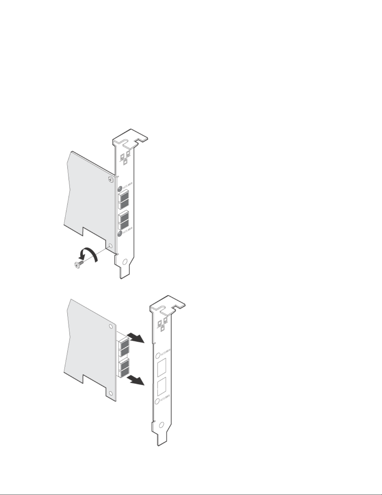
Attaching the Low Profile Bracket (Optional)
Some adapter models come with a small bracket in the product package, to be used in a low profile slot. If you
need to install the adapter in a low-profile slot, follow these instructions.
1. Before handling the adapter, ground yourself to dissipate any static charge.
2. Remove the two screws securing the standard bracket to the back side of the adapter.
3. Slide the bracket away from the adapter.
Page 6
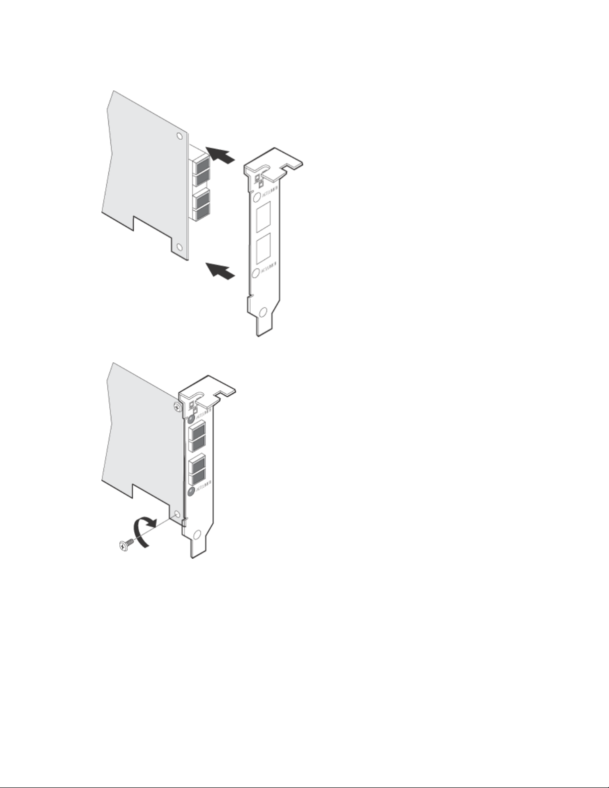
4. Slide the low profile bracket onto the adapter.
5. Attach the low profile bracket to the adapter using the screws you removed in step 2.
6. Carefully tighten the screws until they are seated. Do not over tighten.
You may re-attach the standard sized bracket in the future if necessary.
Installing the Adapter
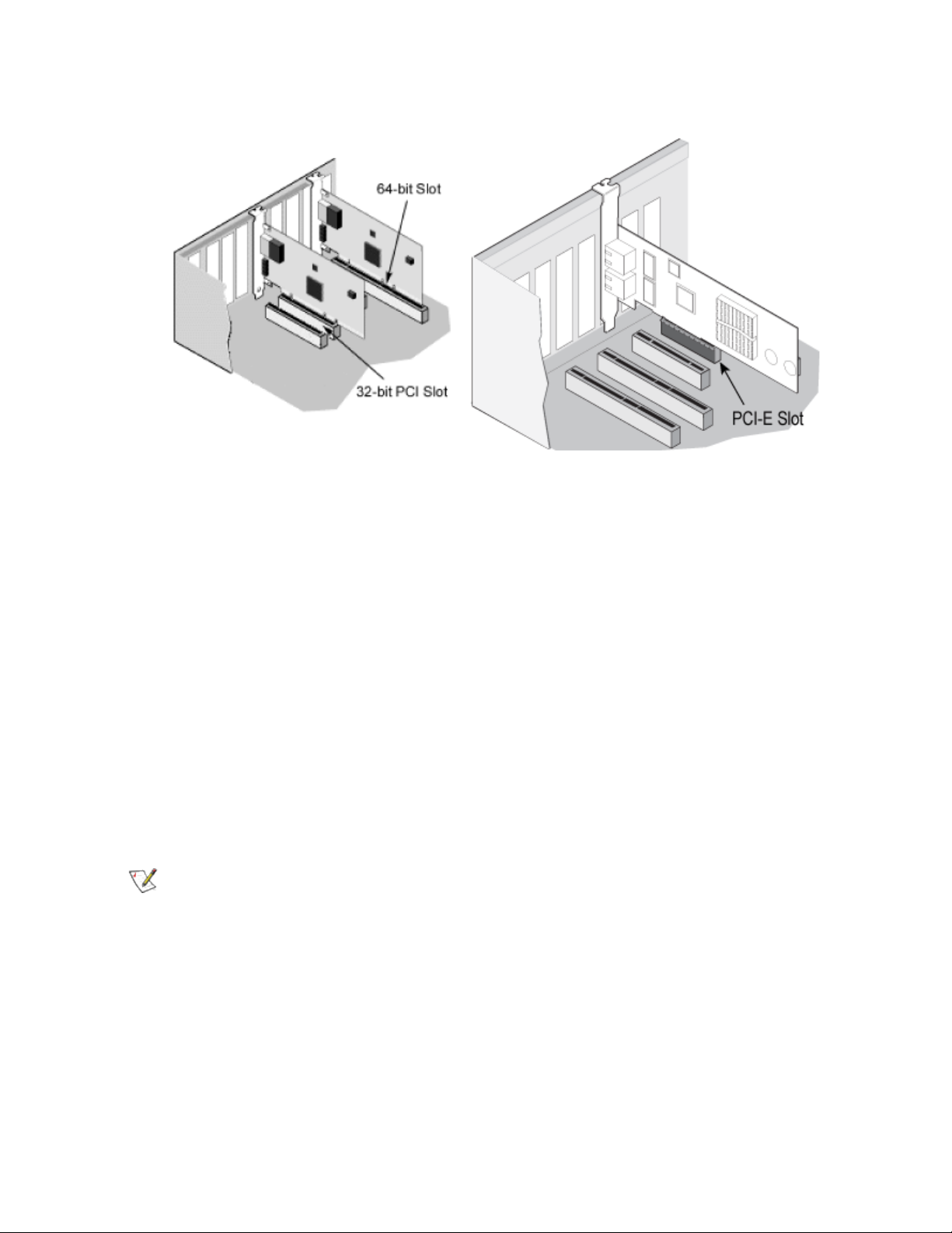
Selecting the Correct Slot
PCI-Express Adapters
l One open PCI-Express slot (v1.0a or newer), x4, x8, or x16.
Page 7

NOTE: The Intel® 10 Gigabit AT Server Adapter will only fit into x8 or larger PCI Express slots.
Some systems have physical x8 PCI Express slots that actually support lower speeds. Please
check your system manual to identify the slot.
PCI and PCI-X Adapters
One of the following slot types, depending on your adapter:
l One open PCI bus master slot, 32-bit or 64-bit, operating at 33 or 66 MHz
l One open PCI-X slot operating at 66, 100 or 133 MHz(recommended)
NOTE: The PRO/1000 MT Quad Port Server adapter requires a 3.3 volt only slot. It cannot be
installed in a 5.0 volt or universal slot.
If you have configuration problems, see your computer's documentation to determine if the PCI slots are bus
master-enabled. If you get a PCI or PCI-X configuration error, select Troubleshooting in the Table of Contents.
Insert the Adapter into the Computer
1. If your computer supports PCI Hot Plug, see your computer documentation for special installation
instructions.
2. Shut down the operating system (if it's running).
3. Turn off and unplug your computer. Then remove the cover.
CAUTION: Turn off and unplug the power before removing the computer's cover. Failure to
do so could endanger you and may damage the adapter or computer.
4. Remove the cover bracket from an appropriate slot.
5. Insert the adapter, pushing it into the slot until the adapter is firmly seated.
l If you install a 64-bit PCI adapter in a 32-bit slot, the adapter will still function, but the end of the
edge connector will be exposed and not connected. If this is the case, make sure the exposed
contacts do not touch anything that would cause an electrical problem.
l If you are installing a PCI-Express adapter, be aware that you can install a smaller PCI-Express
adapter in a larger PCI-Express slot.
Page 8
6. Secure the adapter bracket with a screw, if required.
7. Repeat steps 4 through 6 for each additional adapter to be installed.
8. Replace the computer cover and plug in the power cord.
9. Turn the power on and start your operating system.
Attaching Cables
Intel® Gigabit and 10 Gigabit Network Adapters using copper connections automatically accommodate either
MDI or MDI-X connections. The auto-MDI-X feature of Intel Gigabit Network adapters allows you to directly
connect two adapters without using a cross-over cable.
To ensure compliance with CISPR 24 and the EU's EN55024, Intel® 10 Gigabit Server Adapters and
Connections should be used only with CAT 6a shielded cables that are properly terminated according to the
recommendations in EN50174-2.
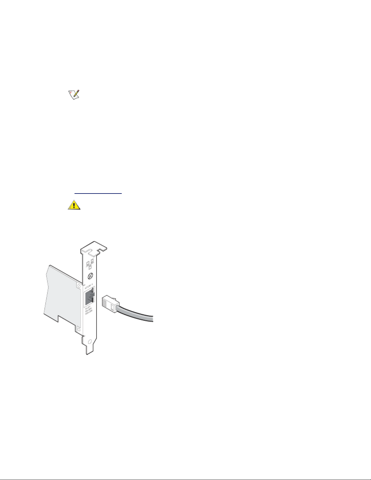
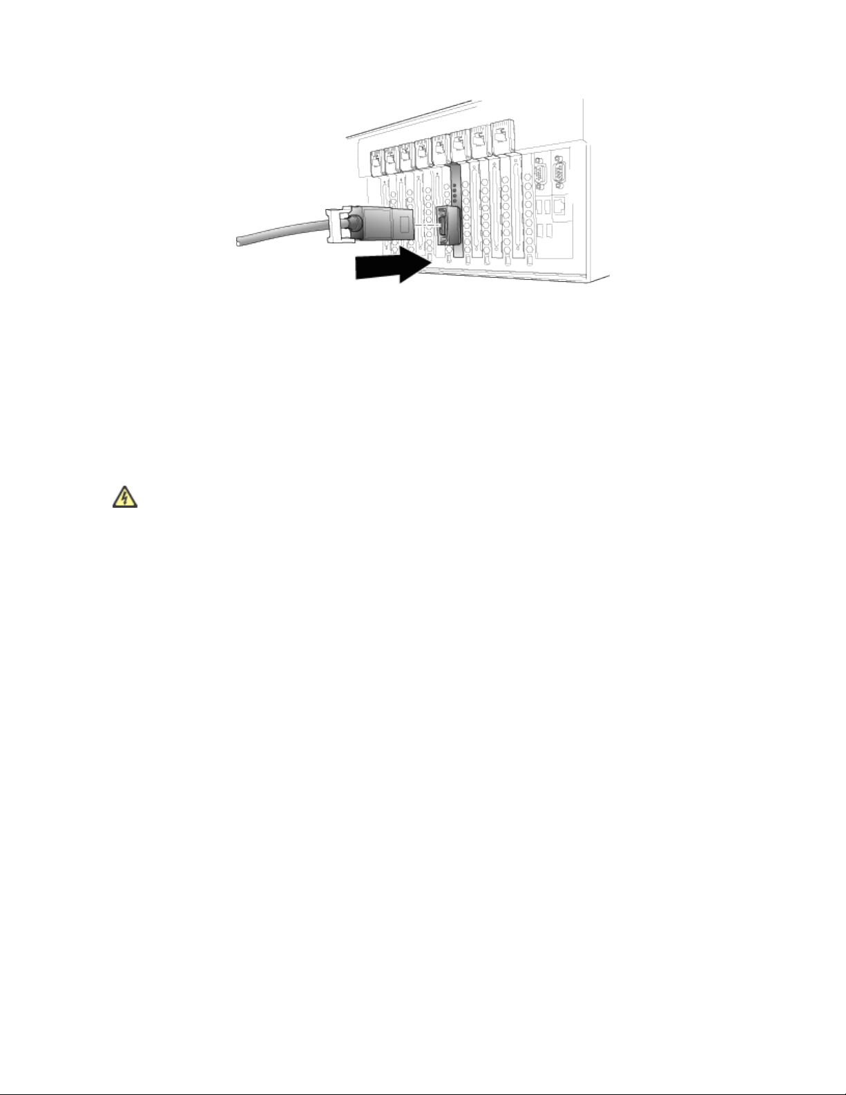
Attach an RJ45 Network Cable
Cable types
Use one of the following types of network cabling, depending on your adapter and the intended use:
NOTE: If you are using this adapter in a residential environment (at any speed), use Category 5 or
better wiring. If the cable runs between rooms or through walls and/or ceilings, it should be
plenum-rated for fire safety.
l Maximum lengths for Intel® 10 Gigabit Server Adapters and Connections that use 10GBASE-T on Cat-
egory 6, Category 6a, or Category 7 wiring, twisted 4-pair copper:
l Maximum length for Category 6 is 55 meters.
l Maximum length for Category 6a is 100 meters.
l Maximum length for Category 7 is 100 meters.
Page 9
l To ensure compliance with CISPR 24 and the EU's EN55024, Intel® 10 Gigabit Server
Adapters and Connections should be used only with CAT 6a shielded cables that are properly
terminated according to the recommendations in EN50174-2.
l For 1000 Mbps operation (1000BaseT), use Category 5 or better (must be 4-pair wiring). Make sure you
use Category 5 cable that complies with the TIA-568 wiring specification.
NOTE: To insure compliance with CISPR 24 and the EU’s EN55024, devices based on
the 82576 controller should be used only with CAT 5E shielded cables that are properly terminated according to the recommendations in EN50174-2.
l For 100 Mbps operation (100BaseTX), use Category 5 wiring or better.
l For 10 Mbps operation (10BaseT), use Category 3 wiring or better.
l In all cases:
l Segment length is limited to 100 meters (328 feet, 1 inch).
l The adapter must be connected to a compatible link partner, and may be set to auto-negotiate
speed and duplex.
l For more information on this specification, see the Telecommunications Industry Association's web-
site: www.tiaonline.org.
CAUTION: If using less than 4-pair cabling, you must manually configure the speed and
duplex setting of the adapter and the link partner. In addition, with 2- and 3-pair cabling the
adapter can only achieve speeds of up to 100Mbps.
Insert the twisted pair, RJ45 network cable as shown.
CX4
Physical cabling characteristics for the Intel® CX4 Dual Port Server Adapter must meet IEEE Std 802.3ak,
Clause 54 specifications. The required cable connector is an MDI latch-type receptacle, as defined by IEC
61076-3-113.
The IEEE standard defines a worst-case cable length of 15 meters, based on 100 O, twinaxial cable
characteristics. However, commercial cable manufacturers may offer enhanced products that will permit
successful operation over greater distances.
Page 10
Fiber Optic Cabling
Remove and save the fiber optic connector cover. Insert a fiber optic cable into the ports on the network
adapter bracket as shown.
Most connectors and ports are keyed for proper orientation. If the cable you are using is not keyed, check to
be sure the connector is oriented properly (transmit port connected to receive port on the link partner, and vice
versa).
The adapter must be connected to a compatible link partner that is operating at the same laser wavelength as
the adapter.
CAUTION: The fiber optic ports contain a Class 1 laser device. When the ports are disconnected,
always cover them with the provided plug. If an abnormal fault occurs, skin or eye damage may result if in close proximity to the exposed ports.
Connecting Fiber Optic SC Cables
The connection requirements are as follows:
l Laser wavelength: 850 nanometer (not visible).
l SX Cable type:
l Multi-mode fiber with 50 micron core diameter; maximum length is 550 meters.
l Multi-mode fiber with 62.5 micron core diameter; maximum length is 275 meters.
l Connector type: SC.
Page 11

Single-port fiber adapter with SC connector
Connecting Fiber Optic LC Cables
l Laser type: 850 nanometer wavelength (not visible).
l SX Cabling:
l Multi-mode fiber with 50 micron core diameter. Maximum length is 550 meters.
l Multi-mode fiber with 62.5 micron core diameter. Maximum length is 275 meters
l Connector type: LC.
"LX" Adapters
Adapters with an "LX" marking on the bracket support the 1000Base-LX connectivity standard. They are
designed for long-haul operation, and have different connectivity requirements:
l Laser type: 1310 nanometer wavelength (not visible).
l LX Cabling: single-mode fiber with 9.0 micron core diameter.
l Maximum length: 10 kilometers.
l Connector type: LC.
NOTES:
l Although LX adapters are designed for use with long-haul single-mode fiber, they can also
be used with short-haul multi-mode fiber. Maximum cable length is 550 meters. Must be
connected to compatible LX ports.
l If needed, an LC-to-SC adapter cable may be used to mate with SC connectors.
Page 12

Single-port fiber adapter with LC connector
SFP+ Devices with Pluggable Optics
X710 and XL710-Based Adapters
NOTES:
l If your Intel(R) Network Adapter came with Intel SFP+ optics, or is an Intel(R) Ethernet
Converged Network Adapter X710 type of adapter, then it only supports Intel optics and/or
the direct attach cables listed below.
Supplier Type Part Numbers
SR Modules
Intel DUAL RATE 1G/10G SFP+ SR (bailed) FTLX8571D3BCV-
IT
Intel DUAL RATE 1G/10G SFP+ SR (bailed) AFBR-703SDDZ-
IN1
LR Modules
Intel DUAL RATE 1G/10G SFP+ LR (bailed) FTLX1471D3BCV-
IT
Intel DUAL RATE 1G/10G SFP+ LR (bailed) AFCT-701SDZ-
IN2
QSFP Modules
Intel TRIPLE RATE 1G/10G/40G QSFP+ SR (bailed) (1G not supported
E40GQSFPSR
on XL710)
Page 13

Intel TRIPLE RATE 1G/10G/40G QSFP+ LR (bailed) (1G not supported
E40GQSFPLR
on XL710)
82599-Based Adapters
NOTES:
l If your 82599-based Intel® Network Adapter came with Intel optics, or is an Intel® Eth-
ernet Server Adapter X520-2, then it only supports Intel optics and/or the direct attach
cables listed below.
l 82599-Based adapters support all passive and active limiting direct attach cables that com-
ply with SFF-8431 v4.1 and SFF-8472 v10.4 specifications.
Supplier Type Part Numbers
SR Modules
Intel DUAL RATE 1G/10G SFP+ SR (bailed) AFBR-703SDZ-
IN2
Intel DUAL RATE 1G/10G SFP+ SR (bailed) FTLX8571D3BCV-
IT
Intel DUAL RATE 1G/10G SFP+ SR (bailed) AFBR-703SDDZ-
IN1
LR Modules
Intel DUAL RATE 1G/10G SFP+ LR (bailed) FTLX1471D3BCV-
IT
Intel DUAL RATE 1G/10G SFP+ LR (bailed) AFCT-701SDZ-
IN2
Intel DUAL RATE 1G/10G SFP+ LR (bailed) AFCT-701SDDZ-
IN1
QSFP Modules
Intel TRIPLE RATE 1G/10G/40G QSFP+ SR (bailed) (40G not sup-
E40GQSFPSR
ported on 82599)
The following is a list of 3rd party SFP+ modules that have received some testing. Not all modules are
applicable to all devices.
Supplier Type Part Numbers
Page 14

Finisar SFP+ SR bailed, 10g single rate FTLX8571D3BCL
Avago SFP+ SR bailed, 10g single rate AFBR-700SDZ
Finisar SFP+ LR bailed, 10g single rate FTLX1471D3BCL
Finisar DUAL RATE 1G/10G SFP+ SR (No Bail) FTLX8571D3QCV-IT
Avago DUAL RATE 1G/10G SFP+ SR (No Bail) AFBR-703SDZ-IN1
Finisar DUAL RATE 1G/10G SFP+ LR (No Bail) FTLX1471D3QCV-IT
Avago DUAL RATE 1G/10G SFP+ LR (No Bail) AFCT-701SDZ-IN1
Finisar 1000BASE-T SFP FCLF8522P2BTL
Avago 1000BASE-T SFP ABCU-5710RZ
HP 1000BASE-SX SFP 453153-001
82598-Based Adapters
NOTES:
l Intel® Network Adapters that support removable optical modules only support their original
module type (i.e., the Intel® 10 Gigabit SR Dual Port Express Module only supports SR
optical modules). If you plug in a different type of module, the driver will not load.
l 82598-Based adapters support all passive direct attach cables that comply with SFF-8431
v4.1 and SFF-8472 v10.4 specifications. Active direct attach cables are not supported.
l Hot Swapping/hot plugging optical modules is not supported.
l Only single speed, 10 gigabit modules are supported.
l LAN on Motherboard (LOMs) may support DA, SR, or LR modules. Other module types are
not supported. Please see your system documentation for details.
The following is a list of SFP+ modules and direct attach cables that have received some testing. Not all
modules are applicable to all devices.
Supplier Type Part Numbers
Page 15

Finisar SFP+ SR bailed, 10g single rate FTLX8571D3BCL
Avago SFP+ SR bailed, 10g single rate AFBR-700SDZ
Finisar SFP+ LR bailed, 10g single rate FTLX1471D3BCL
Molex 1m - Twin-ax cable 74752-1101
Molex 3m - Twin-ax cable 74752-2301
Molex 5m - Twin-ax cable 74752-3501
Molex 10m - Twin-ax cable 74752-9004
Tyco 1m - Twin-ax cable 2032237-2
Tyco 3m - Twin-ax cable 2032237-4
Tyco 5m - Twin-ax cable 2032237-6
Tyco 10m - Twin-ax cable 1-2032237-1
THIRD PARTY OPTIC MODULES AND CABLES REFERRED TO ABOVE ARE LISTED ONLY FOR THE PURPOSE OF HIGHLIGHTI NG THIRD
PARTY SPECIFICATIONS AND POTENTIAL COMPATIBILITY, AND ARE NOT RECOMMENDATIONS OR ENDORSEMENT OR SPONSORSHIP OF
ANY THIRD PARTY'S PRODUCT BY INTEL. INTEL IS NOT ENDORSING OR PROMOTING PRODUCTS MADE BY ANY THIRD PARTY AND THE
THIRD PARTY REFERENCE I S PROVIDED ONLY TO SHARE INFORMATION REGARDING CERTAIN OPTIC MODULES AND CABLES WI TH THE
ABOVE SPECIFICATIONS. THERE MAY BE OTHER MANUFACTURERS OR SUPPLIERS, PRODUCING OR SUPPLYING OPTIC MODULES AND
CABLES WITH SIMILAR OR MATCHING DESCRIPTIONS. CUSTOMERS MUST USE THEIR OWN DISCRETI ON AND DILIGENCE TO PURCHASE
OPTIC MODULES AND CABLES FROM ANY THI RD PARTY OF THEIR CHOICE. CUSTOMERS ARE SOLELY RESPONSIBLE FOR ASSESSING
THE SUITABILIT Y OF THE PRODUCT AND/OR DEVICES AND FOR THE SELECTION OF THE VENDOR FOR PURCHASING ANY PRODUCT. THE
OPTIC MODULES AND CABLES REFERRED TO ABOVE ARE NOT WARRANTED OR SUPPORTED BY INTEL. INTEL ASSUMES NO LIABILITY
WHATSOEVER, AND I NTEL DISCLAIMS ANY EXPRESS OR IMPLIED WARRANTY, RELATING TO SALE AND/OR USE OF SUCH THI RD PARTY
PRODUCTS OR SELECTION OF VENDOR BY CUSTOMERS.
PCI Hot Plug Support
Intel® PRO/100 Server Adapters and most Intel® Gigabit Server Adapters are enabled for use in selected
servers equipped with Hot Plug support.Exceptions: Intel Gigabit Quad Port Server adapters do not support
Hot Plug operations.
If you replace an adapter in a Hot Plug slot, do not place the removed adapter back into the same network until
the server has rebooted (unless you return it to the same slot and same team as before). This prevents a
conflict in having two of the same Ethernet addresses on the same network.
The system will require a reboot if you
l Change the primary adapter designator.
l Add a new adapter to an existing team and make the new adapter the primary adapter.
l Remove the primary adapter from the system and replace it with a different type of adapter.
Page 16

NOTE: To replace an existing SLA-teamed adapter in a Hot Plug slot, first unplug the adapter
cable. When the adapter is replaced, reconnect the cable.
PCI Hot Plug Support for Microsoft* Windows* Operating Systems
Intel® network adapters are enabled for use in selected servers equipped with PCI Hot Plug support and
runningMicrosoft* Windows* operating systems. For more information on setting up and using PCI Hot Plug
support in your server, see your hardware and/or Hot Plug support documentation for details. PCI Hot Plug
only works when you hot plug an identical Intel network adapter.
NOTES:
l The MAC address and driver from the removed adapter will be used by the replacement
adapter unless you remove the adapter from the team and add it back in. If you do not
remove and restore the replacement adapter from the team, and the original adapter is used
elsewhere on your network, a MAC address conflict will occur.
l For SLA teams, ensure that the replacement NIC is a member of the team before con-
necting it to the switch.
Getting the Most From Your Intel® 10 Gigabit Server Adapter
NOTE:These adjustments should be performed by a highly skilled network administrator. They
are not guaranteed to improve performance. Not all settings shown here may be available through
your BIOS, operating system or network driver configuration.
1. Install the adapter in a PCIe x8 slot.
NOTE: Some PCIe x8 slots are actually configured as x4 slots. These slots have
insufficient bandwidth for full 10Gbe line rate with dual port 10GbE devices. The driver can
detect this situation and will write the following message in the system log: “PCI-Express
bandwidth available for this card is not sufficient for optimal performance. For optimal
performance a x8 PCI-Express slot is required.”
If this error occurs, moving your adapter to a true x8 slot will resolve the issue.
2. Use the proper cabling for the adapter you have. See Attach the Network Cable for details.
3. Enable Jumbo Frames, if your other network components can also be configured for it.
4. If your BIOS has an MMRBC (Maximum Memory Read Byte Count) adjustment, change it from its
default (usually 512) to 4096 (maximum).
NOTE: Some systems may set the adapter's MMRBC to 4096 by default.
5. Increase the number of TCP and Socket resources from the default value.
6. Increase the allocation size of Driver Resources (transmit/receive buffers). However, most TCP traffic
patterns work best with the transmit buffer set to its default value, and the receive buffer set to its
minimum value.
Page 17

Advanced Features
NOTE:The options available on the Advanced tab are adapter and system dependent. Not all
adapters will display all options.
Jumbo Frames
Jumbo Frames are Ethernet frames that are larger than 1518 bytes. You can use Jumbo Frames to reduce
server CPU utilization and increase throughput. However, additional latency may be introduced.
NOTES:
l Jumbo Frames are supported at 1000 Mbps and higher. Using Jumbo Frames at 10 or 100
Mbps is not supported and may result in poor performance or loss of link.
l End-to-end network hardware must support this capability; otherwise, packets will be
dropped.
Jumbo Frames can be implemented simultaneously with VLANs and teaming.
To configure Jumbo Frames at the switch, consult your network administrator or switch user's guide.
Jumbo Frame Restrictions:
l Jumbo Frames are not supported in multi-vendor team configurations.
l Supported protocols are limited to IP (TCP, UDP).
l Jumbo Frames require compatible switch connections that forward Jumbo Frames. Contact your
switch vendor for more information.
l The Jumbo Frame setting inside a virtual machine must be the same, or lower than, the setting on the
physical port.
l When standard sized Ethernet frames (64 to 1518 bytes) are used, there is no benefit to configuring
Jumbo Frames.
l The Jumbo Frames setting on the switch must be set to at least 8 bytes larger than the adapter setting
for Microsoft* Windows* operating systems, and at least 22 bytes larger for all other operating systems.
l The Intel® PRO/1000 PL Network Connection supports Jumbo Frames in Microsoft* Windows* oper-
ating systems only when Intel® PROSet for Windows Device Manager is installed.
l The following devices do not support Jumbo Frames larger than 4096 bytes:
l Intel® 82577LM Gigabit Network Connection
l Intel® 82578DM Gigabit Network Connection.
l The following devices do not support Jumbo Frames:
l Intel® 82567V-4 Gigabit Network Connection
l Intel® 82578DC Gigabit Network Connection
l Intel® 82577LC Gigabit Network Connection
l Intel® 82567LF-3 Gigabit Network Connection
l Intel® 82567V-2 Gigabit Network Connection
Page 18

l Intel® 82567LF-2 Gigabit Network Connection
l Intel® 82567V Gigabit Network Connection
l Intel® 82567LF Gigabit Network Connection
l Intel® PRO/1000 Gigabit Server Adapter
l Intel® PRO/1000 PM Network Connection
l Intel® PRO/1000 PM Network Connection
l Intel® 82562V 10/100 Network Connection
l Intel® 82562GT 10/100 Network Connection
l Intel® 82566DM Gigabit Network Connection
l Intel® 82566DC Gigabit Network Connection
l Intel® 82566DC-2 Gigabit Network Connection
l Intel® 82562V-2 10/100 Gigabit Network Connection
l Intel® 82562G-2 10/100 Gigabit Network Connection
l Intel® 82562GT-2 10/100 Gigabit Network Connection
l Intel® 82552 10/100 Network Connection
Setting Up Jumbo Frames in Microsoft* Windows*
NOTE: Jumbo Frames are not supported in multi-vendor team configurations.
1. Open Microsoft* Windows* Device Manager.
2. Open Properties on your adapter.
3. Click the Advanced tab.
4. Select Jumbo Frames from the list of advanced features.
5. Set your desired packet size (based on network capability).
6. Click OK to apply the changes.
All equipment on the network must also support the larger frame size. When setting up Jumbo Frames on
other network devices, be aware that different network devices calculate Jumbo Frame size differently. Some
devices include the header information in the frame size while others do not. Intel adapters do not include
header information in the frame size. When configuring Jumbo Frames on a switch, set the frame size four
bytes higher for CRC, plus four bytes if you are using VLANs or QoS packet tagging.
Advanced Network Services Teaming
Advanced Network Services (ANS) Teaming, a feature of the Advanced Network Services component, lets
you take advantage of multiple adapters in a system by grouping them together. ANS teaming can use
features like fault tolerance and load balancing to increase throughput and reliability. Before you can set up
ANS teaming in Microsoft* Windows*, you must install Intel® PROSet software. For more information, select
Intel PROSet in the Table of Contents (left pane) of this window.
Page 19

NOTES:
l Be sure to use the latest available drivers on all adapters.
l NDIS 6.2 introduced new RSS data structures and interfaces. Because of this, you cannot
enable RSS on teams that contain a mix of adapters that support NDIS 6.2 RSS and
adapters that do not.
l If a team is bound to a Hyper-V virtual NIC, you cannot change the Primary or Secondary
adapter.
l Intel adapters that do not support Intel PROSet may still be included in a team. However,
they are restricted in the same way non-Intel adapters are. See Multi-Vendor Teaming for
more information.
l To assure a common feature set, some advanced features, including hardware offloading,
are automatically disabled when an adapter that does not support Intel PROSet is added to
a team.
l Hot Plug operations in a Multi-Vendor Team may cause system instability. We recom-
mended that you restart the system or reload the team after performing Hot Plug operations
with a Multi-Vendor Team.
l Spanning tree protocol (STP) should be disabled on switch ports connected to teamed
adapters in order to prevent data loss when the primary adapter is returned to service (failback). Alternatively, an activation delay may be configured on the adapters to prevent data
loss when spanning tree is used. Set the Activation Delay on the advanced tab of team
properties.
l ANS teaming of Virtual Function devices inside a Windows 2008 R2 guest running on an
open source hypervisor is supported.
l Fibre Channel over Ethernet/Data Center Bridging will be automatically disabled when an
adapter is added to a team with non-FCoE/DCB capable adapters.
Supported Adapters
Teaming options are supported on Intel® PRO/100, Intel® Gigabit, and Intel® 10GbE adapters. Selected
adapters from other manufacturers are also supported.
Conditions that may prevent you from teaming a device
During team creation or modification, the list of available team types or list of available devices may not
include all team types or devices. This may be caused by any of several conditions, including:
l The operating system does not support the desired team type.
l The device does not support the desired team type or does not support teaming at all.
l The devices you want to team together use different driver versions.
l You are trying to team an Intel PRO/100 device with an Intel 10GbE device.
l TOE (TCP Offload Engine) enabled devices cannot be added to an ANS team and will not appear in the
list of available adapters.
l You can add Intel® Active Management Technology (Intel® AMT) enabled devices to Adapter Fault
Tolerance (AFT), Switch Fault Tolerance (SFT), and Adaptive Load Balancing (ALB) teams. All other
team types are not supported. The Intel AMT enabled device must be designated as the primary
adapter for the team.
Page 20

l The device's MAC address is overridden by the Locally Administered Address advanced setting.
l Fibre Channel over Ethernet (FCoE) Boot has been enabled on the device.
l The device has “OS Controlled” selected on the Data Center tab.
l The device has a virtual NIC bound to it.
l The device is part of a Microsoft* Load Balancing and Failover (LBFO) team.
Microsoft* Load Balancing and Failover (LBFO) teams
Intel ANS teaming and VLANs are not compatible with Microsoft's LBFO teams. Intel® PROSet will block a
member of an LBFO team from being added to an Intel ANS team or VLAN. You should not add a port that is
already part of an Intel ANS team or VLAN to an LBFO team, as this may cause system instability. If you use
an ANS team member or VLAN in an LBFO team, perform the following procedure to restore your
configuration:
1. Reboot the machine
2. Remove LBFO team. Even though LBFO team creation failed, after a reboot Server Manager will report
that LBFO is Enabled, and the LBFO interface is present in the ‘NIC Teaming’ GUI.
3. Remove the ANS teams and VLANS involved in the LBFO team and recreate them. This is an optional
(all bindings are restored when the LBFO team is removed ), but strongly recommended step
NOTE: If you add an Intel AMT enabled port to an LBFO team, do not set the port to Standby in
the LBFO team. If you set the port to Standby you may lose AMT functionality.
ANS Teaming Types
l Adapter Fault Tolerance (AFT) - provides automatic redundancy for a server's network connection. If
the primary adapter fails, the secondary adapter takes over. Adapter Fault Tolerance supports two to
eight adapters per team. This teaming type works with any hub or switch. All team members must be
connected to the same subnet.
l Switch Fault Tolerance (SFT) - provides failover between two adapters connected to separate
switches. Switch Fault Tolerance supports two adapters per team. Spanning Tree Protocol (STP) must
be enabled on the switch when you create an SFT team. When SFT teams are created, the Activation
Delay is automatically set to 60 seconds. This teaming type works with any switch or hub. All team
members must be connected to the same subnet.
l Adaptive Load Balancing (ALB) - provides load balancing of transmit traffic and adapter fault tolerance.
In Microsoft* Windows* operating systems, you can also enable or disable receive load balancing
(RLB) in ALB teams (by default, RLB is enabled).
l Virtual Machine Load Balancing (VMLB) - provides transmit and receive traffic load balancing across
Virtual Machines bound to the team interface, as well as fault tolerance in the event of switch port,
cable, or adapter failure. This teaming type works with anyswitch.
l Static Link Aggregation (SLA) - provides increased transmission and reception throughput in a team of
two to eight adapters. This team type replaces the following team types from prior software releases:
Fast EtherChannel*/Link Aggregation (FEC) and Gigabit EtherChannel*/Link Aggregation (GEC). This
type also includes adapter fault tolerance and load balancing (only routed protocols). This teaming type
requires a switch with Intel Link Aggregation, Cisco* FEC or GEC, or IEEE 802.3ad Static Link Aggregation capability.
Page 21

All adapters in a Link Aggregation team running in static mode must run at the same speed and must be
connected to a Static Link Aggregation capable switch. If the speed capability of adapters in a Static
Link Aggregation team are different, the speed of the team is dependent on the lowest common
denominator.
l IEEE 802.3ad Dynamic Link Aggregation - creates one or more teams using Dynamic Link Aggregation
with mixed-speed adapters. Like the Static Link Aggregation teams, Dynamic 802.3ad teams increase
transmission and reception throughput and provide fault tolerance. This teaming type requires a switch
that fully supports the IEEE 802.3ad standard.
l Multi-Vendor Teaming (MVT) -adds the capability to include adapters from selected other vendors in a
team. If you are using a Windows-based computer, you can team adapters that appear in the Intel
PROSet teaming wizard.
IMPORTANT:
l Be sure to use the latest available drivers on all adapters.
l Before creating a team, adding or removing team members, or changing advanced settings
of a team member, make sure each team member has been configured similarly. Settings
to check include VLANs and QoS Packet Tagging, Jumbo Frames, and the various offloads. These settings are available in Intel PROSet's Advanced tab. Pay particular atten-
tion when using different adapter models or adapter versions, as adapter capabilities vary.
l If team members implement Advanced features differently, failover and team functionality
will be affected. To avoid team implementation issues:
l Create teams that use similar adapter types and models.
l Reload the team after adding an adapter or changing any Advanced features. One
way to reload the team is to select a new preferred primary adapter. Although there
will be a temporary loss of network connectivity as the team reconfigures, the team
will maintain its network addressing schema.
NOTES:
l Hot Plug operations for an adapter that is part of a team are only available in Windows
Server.
l For SLA teams, all team members must be connected to the same switch. For AFT, ALB,
and RLB teams, all team members must belong to the same subnet. The members of an
SFT team must be connected to a different switch.
l Teaming only one adapter port is possible, but provides no benefit.
Primary and Secondary Adapters
If the primary adapter fails, another adapter will take over its duties. If you are using more than two adapters,
and you want a specific adapter to take over if the primary fails, you must specify a secondary adapter. If an
Intel AMT enabled device is part of a team, it must be designated as the primary adapter for the team.
There are two types of primary and secondary adapters:
l Default primary adapter: If you do not specify a preferred primary adapter, the software will choose
an adapter of the highest capability (model and speed) to act as the default primary. If a failover occurs,
another adapter becomes the primary. The adapter will, however, rejoin the team as a non-primary.
Page 22

l Preferred Primary/Secondary adapters: You can specify a preferred adapter in Intel PROSet. Under
normal conditions, the Primary adapter handles all non-TCP/IP traffic. The Secondary adapter will
receive fallback traffic if the primary fails. If the Preferred Primary adapter fails, but is later restored to
an active status, control is automatically switched back to the Preferred Primary adapter.
To specify a preferred primary or secondary adapter
1. From Device Manager, open the properties of a team.
2. Click the Settings tab.
3. Click the Modify Team button.
4. Select the adapter you want to be the primary adapter and click the Set Primary button.
The adapter's preferred setting appears in the Priority column.
Failover and Failback
When a link fails, either because of port or cable failure, team types that provide fault tolerance will continue to
send and receive traffic. Failover is the initial transfer of traffic from the failed link to a good link. Failback
occurs when the original adapter regains link. You can use the Activation Delay setting (located on the
Advanced tab of the team's properties in Device Manager) to specify a how long the failover adapter waits
before becoming active. If you don't want your team to failback when the original adapter gets link back, you
can set the Allow Failback setting to disabled (located on the Advanced tab of the team's properties in Device
Manager).
Adapter Fault Tolerance
Adapter Fault Tolerance (AFT) provides the safety of an additional backup link between the server and switch.
In the case of switch port, cable, or adapter failure, network connectivity is maintained.
Adapter Fault Tolerance is implemented with a primary adapter and one or more backup, or secondary
adapters. During normal operation, the backup adapters are in standby. If the link to the primary adapter fails,
the link to the secondary adapter automatically takes over. For more information, see Primary and Secondary
Adapters.
To use Adapter Fault Tolerance all adapters must be connected to the same subnet.
Switch Fault Tolerance
Switch Fault Tolerance (SFT) teaming allows you to connect each of two teamed adapters to a separate
switch.
Switch Fault Tolerance can detect failures when they occur:
l on either teamed adapter
l on either cable connecting the teamed adapter to its switch
l on switch ports connected to the adapters, if link is lost
In SFT teams, one adapter is the primary adapter and one adapter is the secondary adapter. During normal
operation, the secondary adapter is in standby. In standby, the adapter is inactive and waiting for failover to
occur. It does not transmit or receive other network traffic. If the primary adapter loses connectivity, the
secondary adapter automatically takes over.
In SFT teams, each adapter in the team can operate at a different speed than the other.
Page 23

Configuration Monitoring
You can set up monitoring between an SFT team and up to five IP addresses. This allows you to detectlink
failure beyond the switch. You can ensure connection availability for several clients that you consider critical.
If the connection between the primary adapter and all of the monitored IP addresses is lost, the team will
failover to the secondary adapter.
Adaptive Load Balancing
Adaptive Load Balancing (ALB) uses software to balance routable traffic among a team of two to eight
adapters or LOMs (the team must include at least one server adapter) connected to the same subnet. The
software analyzes the send and transmit loading on each adapter and balances the rate across the adapters
based on destination address. Adapter teams configured for ALB also provide the benefits of fault tolerance.
NOTES:
l ALB does not load balance non-routed protocols such as NetBEUI and some IPX* traffic.
l You can create an ALB team with mixed speed adapters. The load is balanced according to
the lowest common denominator of adapter capabilities and the bandwidth of the channel.
l On Windows systems, Receive Load Balancing is enabled by default.
l Receive Load Balancing is not supported on Microsoft Hyper-V*.
Virtual Machine Load Balancing
Virtual Machine Load Balancing (VMLB) provides transmit and receive traffic load balancing across Virtual
Machines bound to the team interface, as well as fault tolerance in the event of switch port, cable, or adapter
failure.
The driver analyzes the transmit and receive load on each member adapter and balances the traffic across
member adapters. In a VMLB team, each Virtual Machine is associated with one team member for its TX and
RX traffic.
If only one virtual NIC is bound to the team, or if Hyper-V is removed, then the VMLB team will act like an ALB
team.
NOTES:
l VMLB does not load balance non-routed protocols such as NetBEUI and some IPX* traffic.
l VMLB supports from two to eight adapter ports per team.
l You can create an VMLB team with mixed speed adapters. The load is balanced according
to the lowest common denominator of adapter capabilities and the bandwidth of the channel.
l You cannot use an Intel AMT enabled adapter in a VMLB team.
Static Link Aggregation
Static Link Aggregation (SLA) is a performance technology developed by Cisco to increase throughput
between switches. This team type works with:
l Cisco EtherChannel-capable switches with channeling mode set to 'ON'
l Intel switches capable of Link Aggregation
l Other switches capable of static 802.3ad
Page 24

The transmission speed will never exceed the adapter base speed to any single address (per specification).
Teams can contain two to eight adapters, but must match the capability of the switch. Adapter teams
configured for Static Link Aggregation also provide the benefits of fault tolerance and load balancing.
NOTE: You cannot use an Intel AMT enabled adapter in an SLA team
IEEE 802.3ad Dynamic Link Aggregation
802.3ad is an adopted IEEE standard.Teams can contain two to eight adapters, and you can have a
maximum of two IEEE 802.3ad dynamic teams per server. You must use 802.3ad switches (in dynamic
mode, aggregation can go across switches). Adapter teams configured for IEEE 802.3ad also provide the
benefits of fault tolerance and load balancing. Under 802.3ad, all protocols can be load balanced.
Dynamic mode supports multiple aggregators. Aggregators are formed by port speed connected to a switch.
For example, a team can contain adapters running at 1 Gbps and 10 Gbps, but two aggregators will be formed,
one for each speed. Also, if a team contains 1 Gbps ports connected to one switch, and a combination of
1Gbps and 10Gbps ports connected to a second switch, three aggregators would be formed. One containing
all the ports connected to the first switch, one containing the 1Gbps ports connected to the second switch,
and the third containing the 10Gbps ports connected to the second switch.
NOTES:
l Once you choose an aggregator, it remains in force until all adapters in that aggregator lose
link.
l In some switches, copper and fiber adapters cannot belong to the same aggregator in an
IEEE 802.3ad configuration. If there are copper and fiber adapters installed in a system,
the switch might configure the copper adapters in one aggregator and the fiber-based
adapters in another. If you experience this behavior, for best performance you should use
either copper or fiber-based adapters in a system.
l If multiple switches are used, all team members connected to the same switch must oper-
ate at the same speed.
l You cannot use an Intel AMT enabled adapter in a DLA team.
Before you begin
l Verify that the switch fully supports the IEEE 802.3ad standard.
l Check your switch documentation for port dependencies. Some switches require pairing to start on a
primary port.
l Check your speed and duplex settings to ensure the adapter and switch are running at full duplex,
either forced or set to auto-negotiate. Both the adapter and the switch must have the same speed and
duplex configuration.The full duplex requirement is part of the IEEE 802.3ad specification: http://stand-
ards.ieee.org/
If needed, change your speed or duplex setting beforeyou link the adapter to the switch. Although you
can change speed and duplex settings after the team is created,Intel recommends you disconnect the
cables until settings are in effect. In some cases, switches or servers might not appropriately
recognize modified speed or duplex settings if settings are changed when there is an active link to the
network.
Page 25

l If you are configuring a VLAN, check your switch documentation for VLAN compatibility notes. Not all
switches support simultaneous dynamic 802.3ad teams and VLANs. If you choose to set up VLANs,
configure teaming and VLAN settings on the adapter before you link the adapter to the switch. Setting
up VLANs after the switch has created an active aggregator affects VLAN functionality.
Multi-Vendor Teaming
MVT allows teaming with a combination of Intel adapters that support Intel PROSet, Intel adapters that do not
support Intel PROSet, and non-Intel adapters. This feature is currently available under Windows Server.All
adapters that appear in the Intel PROSet teaming wizard can be included in a team.
MVT Design Considerations
l In order to activate MVT, you must have at least one Intel adapter or integrated connection that sup-
ports Intel PROSet in the team. That adapter or connection must be designated as the primary
adapter.
l A multi-vendor team can be created for any team type.
l All members in a MVT must operate on a common feature set (lowest common denominator).
l Manually verify that the frame setting for all adapters in the team is the same.
l Verify that the RSS settings for all adapters in the team are the same.
Virtual LANs
The term VLAN (Virtual Local Area Network) refers to a collection of devices that communicate as if they
were on the same physical LAN. Any set of ports (including all ports on the switch) can be considered a
VLAN. LAN segments are not restricted by the hardware that physically connects them.
VLANs offer the ability to group computers together
into logical workgroups. This can simplify network
administration when connecting clients to servers
that are geographically dispersed across the
building, campus, or enterprise network.
Typically, VLANs consist of co-workers within the
same department but in different locations, groups
of users running the same network protocol, or a
cross-functional team working on a joint project.
By using VLANs on your network, you can:
l Improve network performance
l Limit broadcast storms
l Improve LAN configuration updates (adds, moves, and changes)
l Minimize security problems
l Ease your management task
Other Considerations
l To set up IEEE VLAN membership (multiple VLANs), the adapter must be attached to a switch with
IEEE 802.1Q VLAN capability.
l A maximum of 64 VLANs per network port or team are supported by Intel software.
Page 26

l VLANs can co-exist with teaming (if the adapter supports both). If you do this, the team must be
defined first, then you can set up your VLAN.
l The Intel PRO/100 VE and VM Desktop Adapters and Network Connections can be used in a switch
based VLAN but do not support IEEE Tagging.
l You can set up only one untagged VLAN per adapter or team. You must have at least one tagged
VLAN before you can set up an untagged VLAN.
CAUTION: When using IEEE 802 VLANs, settings must match between the switch and those
adapters using the VLANs.
NOTE: Intel ANS VLANs are not compatible with Microsoft's Load Balancing and Failover (LBFO)
teams. Intel® PROSet will block a member of an LBFO team from being added to an Intel ANS
VLAN. You should not add a port that is already part of an Intel ANS VLAN to an LBFO team, as
this may cause system instability.
Configuring VLANs in Microsoft* Windows*
In Microsoft* Windows*, you must use Intel® PROSet to set up and configure VLANs. For more information,
select Intel PROSet in the Table of Contents (left pane) of this window.
NOTES:
l If you change a setting under the Advanced tab for one VLAN, it changes the settings for
all VLANS using that port.
l In most environments, a maximum of 64 VLANs per network port or team are supported by
Intel PROSet.
l ANS VLANs are not supported on adapters and teams that have VMQ enabled. However,
VLAN filtering with VMQ is supported via the Microsoft Hyper-V VLAN interface. For more
information see Microsoft Hyper-V virtual NICs on teams and VLANs.
l You can have different VLAN tags on a child partition and its parent. Those settings are
separate from one another, and can be different or the same. The only instance where the
VLAN tag on the parent and child MUST be the same is if you want the parent and child partitions to be able to communicate with each other through that VLAN. For more information
see Microsoft Hyper-V virtual NICs on teams and VLANs.
Power Management
The Intel® PROSet Power Management tab replaces the standard Microsoft* Windows* Power Management
tab in Device Manager. It includes the Power Saver and Wake on LAN* (WoL*) options that were previously
included on the Advanced tab. The standard Windows power management functionality is incorporated on the
Intel PROSet tab.
Page 27

NOTES:
l The options available on the Power Management tab are adapter and system dependent.
Not all adapters will display all options.
l The following adapters support WoL only on Port A:
l Intel® Ethernet Server Adapter I350-T2
l Intel® Ethernet Server Adapter I350-T4
l Intel® Ethernet Server Adapter I340-T2
l Intel® Ethernet Server Adapter I340-T4
l Intel® Ethernet Server Adapter I340-F4
l Intel® Gigabit ET2 Quad Port Server Adapter
l Intel® PRO/1000 PF Quad Port Server Adapter
l Intel® PRO/1000 PT Quad Port LP Server Adapter
l Intel® PRO/1000 PT Quad Port Server Adapter
l Intel® PRO/1000 PT Dual Port Network Connection
l Intel® PRO/1000 PT Dual Port Server Connection
l Intel® PRO/1000 PT Dual Port Server Adapter
l Intel® PRO/1000 PF Dual Port Server Adapter
l Intel® Gigabit PT Quad Port Server ExpressModule
l The following adapters do not support WoL:
l Intel® PRO/1000 MT Quad Port Server adapter
l Intel® Gigabit VT Quad Port Server Adapter
l Intel® Ethernet Server Adapter X520-2
l Intel® Ethernet Server Adapter X520-1
l Intel® Ethernet Server Adapter X540-T1
l Intel® Ethernet Converged Network Adapter X540-T2
l Intel® Ethernet Converged Network Adapter X540-T1
NOTE: If your system has a Manageability Engine, the Link LED may stay lit even if WoL is
disabled.
Power Options
The Intel PROSet Power Management tab includes several settings that control the adapter's power
consumption. For example, you can set the adapter to reduce its power consumption if the cable is
disconnected.
If Reduce speed during standby is enabled, then Wake on Magic Packet and/or Wake on directed
packet must be enabled. If both of these options are disabled, power is removed from the adapter during
standby. Wake on Magic Packet from power off state has no effect on this option.
Page 28

Energy Efficient Ethernet
The Energy Efficient Ethernet (EEE) feature allows a capable device to enter Low Power Idle between bursts
of network traffic. Both ends of a link must have EEE enabled for any power to be saved. Both ends of the link
will resume full power when data needs to be transmitted. This transition may introduce a small amount of
network latency.
NOTES:
l Both ends of the EEE link must automatically negotiate link
speed.
l EEE is not supported at 10Mbps.
Intel® Auto Connect Battery Saver
The Intel® Auto Connect Battery Saver (ACBS) feature turns off the adapter when link is down or the network
cable is disconnected. After a timeout period, the adapter will power off. When the network cable is
reconnected and link is restored, the NIC powers up and functionality is fully restored.
ACBS only functions when the system is on battery power. If the power cable is connected, ACBS will be
automatically disabled. If ACBS is active, the adapter will appear to be powered off. If you have Intel®
PROSet installed, on the Link Speed tab, the Link Status will indicate Speed: Not connected. Power off.
NOTE: ACBS will not function on an adapter if the adapter has forced speed or duplex settings.
ACBS will only function if the adapter is set to auto-detect or auto-negotiate.
Intel® System Idle Power Saver
The Intel® System Idle Power Saver feature sets the adapter to negotiate the lowest possible speed setting
when the system and network are idle. When the system activity is detected, the link will be negotiated to a
higher speed.
To support this feature, the adapter must be
l configured to Auto Detect speed and
l connected to a link partner that can auto-negotiate speed
Remote Wake-Up and Wake on LAN*
Microsoft Windows and Windows Server do not support wake from a power-off (S5) state, only from standby
(S3) or hibernate (S4). When shutting down the system, they shutdown ACPI devices, including Intel
adapters. This disarms the adapters remote wake up capability. However, in some ACPI-capable computers,
the BIOS may have a setting that allows you to override the operating system and wake from an S5 state
anyway. If there is no support for wake from S5 state in your BIOS settings, you are limited to Wake From
Standby when using these operating systems.
Wake on Intel® Ready Access
Intel® Ready Access keeps your network connection active when the rest of your system is in sleep or
standby mode, so that content on your system is readily accessible. Requests from other computers will
wake up your computer.
Page 29

Quality of Service
Quality of Service (QoS) allows the adapter to send and receive IEEE 802.3ac tagged frames. 802.3ac tagged
frames include 802.1p priority-tagged frames and 802.1Q VLAN-tagged frames. In order to implement QoS,
the adapter must be connected to a switch that supports and is configured for QoS. Priority-tagged frames
allow programs that deal with real-time events to make the most efficient use of network bandwidth. High
priority packets are processed before lower priority packets.
Tagging is enabled and disabled in Microsoft* Windows* Server* using the "QoS Packet Tagging" field in the
Advanced tab in Intel® PROSet. For other versions of the Windows operating system, tagging is enabled
using the "Priority/VLAN Tagging" setting on the Advanced tab in Intel® PROSet.
Once QoS is enabled in Intel PROSet, you can specify levels of priority based on IEEE 802.1p/802.1Q frame
tagging.
The supported operating systems, including Microsoft* Windows Server*, have a utility for 802.1p packet
prioritization. For more information, see the Windows system help and Microsoft's knowledge base.
NOTE: The first generation Intel® PRO/1000 Gigabit Server Adapter (PWLA 8490) does not
support QoS frame tagging.
Data Center Bridging
Data Center Bridging (DCB) is a collection of standards-based extensions to classical Ethernet. It provides a
lossless data center transport layer that enables the convergence of LANs and SANs onto a single unified
fabric.
Furthermore, DCB is a configuration Quality of Service implementation in hardware. It uses the VLAN priority
tag (802.1p) to filter traffic. That means that there are 8 different priorities that traffic can be filtered into. It also
enables priority flow control (802.1Qbb) which can limit or eliminate the number of dropped packets during
network stress. Bandwidth can be allocated to each of these priorities, which is enforced at the hardware level
(802.1Qaz).
Adapter firmware implements LLDP and DCBX protocol agents as per 802.1AB and 802.1Qaz respectively.
The firmware based DCBX agent runs in willing mode only and can accept settings from a DCBX capable
peer. Software configuration of DCBX parameters via dcbtool/lldptool are not supported.
NOTE: On Microsoft Windows, Data Center Bridging (DCB) is only supported on NVM version
4.52 and newer. Older NVM versions must be updated before the adapter is capable of DCB
support in Windows.
Microsoft* Hyper-V* Overview
Microsoft* Hyper-V* makes it possible for one or more operating systems to run simultaneously on the same
physical system as virtual machines. This allows you to consolidate several servers onto one system, even if
they are running different operating systems. Intel® Network Adapters work with, and within, Microsoft
Hyper-V virtual machines with their standard drivers and software.
Page 30

NOTES:
l Some virtualization options are not available on some adapter/operating system com-
binations.
l The jumbo frame setting inside a virtual machine must be the same, or lower than, the set-
ting on the physical port.
l See http://www.intel.com/technology/advanced_comm/virtualization.htm for more inform-
ation on using Intel Network Adapters in virtualized environments.
Using Intel®Network Adapters in a Hyper-V Environment
When a Hyper-V Virtual NIC (VNIC) interface is created in the parent partition, the VNIC takes on the MAC
address of the underlying physical NIC. The same is true when a VNIC is created on a team or VLAN. Since
the VNIC uses the MAC address of the underlying interface, any operation that changes the MAC address of
the interface (for example, setting LAA on the interface, changing the primary adapter on a team, etc.), will
cause the VNIC to lose connectivity. In order to prevent this loss of connectivity, Intel® PROSet will not allow
you to change settings that change the MAC address.
NOTES:
l If Fibre Channel over Ethernet (FCoE)/Data Center Bridging (DCB) is present on the port,
configuring the device in Virtual Machine Queue (VMQ) + DCB mode reduces the number
of VMQ VPorts available for guest OSes. This does not apply to Intel® Ethernet Controller
X710 based devices.
l When sent from inside a virtual machine, LLDP and LACP packets may be a security risk.
The Intel® Virtual Function driver blocks the transmission of such packets.
l The Virtualization setting on the Advanced tab of the adapter's Device Manager property
sheet is not available if the Hyper-V role is not installed.
l While Microsoft supports Hyper-V on the Windows* 8 client OS, Intel® Ethernet adapters
do not support virtualization settings (VMQ, SR-IOV) on Windows 8 client.
l ANS teaming of VF devices inside a Windows 2008 R2 guest running on an open source
hypervisor is supported.
The Virtual Machine Switch
The virtual machine switch is part of the network I/O data path. It sits between the physical NIC and the
virtual machine NICs and routes packets to the correct MAC address. Enabling Virtual Machine Queue (VMQ)
offloading in Intel(R) ProSet will automatically enable VMQ in the virtual machine switch. For driver-only
installations, you must manually enable VMQ in the virtual machine switch.
Using ANS VLANs
If you create ANS VLANs in the parent partition, and you then create a Hyper-V Virtual NIC interface on an
ANS VLAN, then the Virtual NIC interface *must* have the same VLAN ID as the ANS VLAN. Using a
different VLAN ID or not setting a VLAN ID on the Virtual NIC interface will result in loss of communication on
that interface.
Virtual Switches bound to an ANS VLAN will have the same MAC address as the VLAN, which will have the
same address as the underlying NIC or team. If you have several VLANs bound to a team and bind a virtual
switch to each VLAN, all of the virtual switches will have the same MAC address. Clustering the virtual
Page 31

switches together will cause a network error in Microsoft’s cluster validation tool. In some cases, ignoring this
error will not impact the performance of the cluster. However, such a cluster is not supported by Microsoft.
Using Device Manager to give each of the virtual switches a unique address will resolve the issue. See the
Microsoft Technet article Configure MAC Address Spoofing for Virtual Network Adapters for more
information.
Virtual Machine Queues (VMQ) and SR-IOV cannot be enabled on a Hyper-V Virtual NIC interface bound to a
VLAN configured using the VLANs tab in Windows Device Manager.
Using an ANS Team or VLAN as a Virtual NIC
If you want to use a team or VLAN as a virtual NIC you must follow these steps:
NOTES:
l This applies only to virtual NICs created on a team or VLAN. Virtual NICs created on a
physical adapter do not require these steps.
l Receive Load Balancing (RLB) is not supported in Hyper-V. Disable RLB when using
Hyper-V.
1. Use Intel® PROSet to create the team or VLAN.
2. Open the Network Control Panel.
3. Open the team or VLAN.
4. On the General Tab, uncheck all of the protocol bindings and click OK.
5. Create the virtual NIC. (If you check the "Allow management operating system to share the network
adapter." box you can do the following step in the parent partition.)
6. Open the Network Control Panel for the Virtual NIC.
7. On the General Tab, check the protocol bindings that you desire.
NOTE: This step is not required for the team. When the Virtual NIC is created, its protocols
are correctly bound.
Command Line for Microsoft Windows Server* Core
Microsoft Windows Server* Core does not have a GUI interface. If you want to use an ANS Team or VLAN as
a Virtual NIC, you must use the prosetcl.exe utility to set up the configuration. Use the prosetcl.exe utility to
create the team or VLAN. See the prosetcl.txt file for installation and usage details.
NOTE: Support for the Intel PROSet command line utilities (prosetcl.exe and crashdmp.exe) is
being removed. This functionality will be replaced by the Intel Netcmdlets for Microsoft* Windows
PowerShell*. Please transition all of your scripts and processes to use the Intel Netcmdlets for
Microsoft Windows PowerShell.
The following is an example of how to set up the configuration using prosetcl.exe.
1. Use prosetcl.exe to create a team.
prosetcl.exe Team_Create 1,2,3 TeamNew VMLB
(VMLB is a dedicated teaming mode for load balancing under Hyper-V.)
Page 32

2. Create the virtual NIC by running a remote Hyper-V manager on a different machine. Please see
Microsoft's documentation for instructions on how to do this.
The following is an example of how to set up the configuration using Microsoft* Windows PowerShell*.
1. Get all the adapters on the system and store them into a variable.
$a = Get-IntelNetAdapter
2. Create a team by referencing the indexes of the stored adapter array.
New-IntelNetTeam -TeamMembers $a[1],$a[2] -TeamMode
VirtualMachineLoadBalancing -TeamName “Team1”
Virtual Machine Queue Offloading
Enabling VMQ offloading increases receive and transmit performance, as the adapter hardware is able to
perform these tasks faster than the operating system. Offloading also frees up CPU resources. Filtering is
based on MAC and/or VLAN filters. For devices that support it, VMQ offloading is enabled in the host partition
on the adapter's Device Manager property sheet, under Virtualization on the Advanced Tab.
Each Intel® Ethernet Adapter has a pool of virtual ports that are split between the various features, such as
VMQ Offloading, SR-IOV, Data Center Bridging (DCB), and Fibre Channel over Ethernet (FCoE). Increasing
the number of virtual ports used for one feature decreases the number available for other features. On devices
that support it, enabling DCB reduces the total pool available for other features to 32. Enabling FCoE further
reduces the total pool to 24.
NOTE: This does not apply to devices based on the Intel® Ethernet X710 or XL710 controllers.
Intel PROSet displays the number of virtual ports available for virtual functions under Virtualization properties
on the device's Advanced Tab. It also allows you to set how the available virtual ports are distributed between
VMQ and SR-IOV.
Teaming Considerations
l If VMQ is not enabled for all adapters in a team, VMQ will be disabled for the team.
l If an adapter that does not support VMQ is added to a team, VMQ will be disabled for the team.
l Virtual NICs cannot be created on a team with Receive Load Balancing enabled. Receive Load Balan-
cing is automatically disabled if you create a virtual NIC on a team.
l If a team is bound to a Hyper-V virtual NIC, you cannot change the Primary or Secondary adapter.
SR-IOV (Single Root I/O Virtualization)
SR-IOV lets a single network port appear to be several virtual functions in a virtualized environment. If you
have an SR-IOV capable NIC, each port on that NIC can assign a virtual function to several guest partitions.
The virtual functions bypass the Virtual Machine Manager (VMM), allowing packet data to move directly to a
guest partition's memory, resulting in higher throughput and lower CPU utilization. SR-IOV also allows you to
move packet data directly to a guest partition's memory. SR-IOV support was added in Microsoft Windows
Server 2012. See your operating system documentation for system requirements.
For devices that support it, SR-IOV is enabled in the host partition on the adapter's Device Manager property
sheet, under Virtualization on the Advanced Tab. Some devices may need to have SR-IOV enabled in a
preboot environment.
Page 33

NOTES:
l You must enable VMQ for SR-IOV to function.
l SR-IOV is not supported with ANS teams.
Network Virtualization using Generic Routing Encapsulation (NVGRE)
Network Virtualization using Generic Routing Encapsulation (NVGRE) increases the efficient routing of
network traffic within a virtualized or cloud environment. Some Intel® Ethernet Network devices perform
Network Virtualization using Generic Routing Encapsulation (NVGRE) processing, offloading it from the
operating system. This reduces CPU utilization.
Intel®Active Management Technology
Intel® Active Management Technology (Intel® AMT) is a hardware-based solution that uses out-of-band
communication for management access to networked client computers. Even when the client computer is
powered down or has a non-operational OS, Intel AMT enables you to access and manage the system over
the network. You can easily get accurate platform information, and can perform remote updating, diagnostics,
debugging, and repair of a system, regardless of the state of the OS and the power state of the system. For
example, if an OS has failed, you can establish a remote-control session to the failed system and then
remotely reboot the failed system to a known good OS image on a remote drive. After the system reboots, you
can remotely manage the reinstallation of the OS or repair.
For more information on Intel AMT features, see the documentation that came with your system.
NOTE:Intel Active Management Technology drivers are installed as part of the base driver
installation on Intel AMT capable systems.
Locally Administered Address (LAA)
The Locally Administered Address feature allows you to override a device’s MAC Address and assign an
address of your choice. The address is a 12-digit hexadecimal number in the range: 0000 0000 0001 – FEFF
FFFF FFFF.
CAUTION: Make sure no other systems on the network use this address.
NOTES:
l Do not use a multicast address (least significant bit of the high byte = 1).
For example, in the address 0y123456789A, "y" cannot be an odd number. (y must be 0, 2,
4, 6, 8, A, C, or E.)
l To restore the default MAC address, click Use Default.
l You cannot change the address if the adapter is part of a team.
l Changing this setting may cause a momentary loss of connectivity.
The LAA setting is disabled and cannot be changed because one or more of the following is true:
l The device is configured to iSCSI boot primary or secondary.
l The device or team is bound to the Microsoft Virtual Switch Protocol.
Page 34

Low Latency Interrupts (LLI)
The LLI feature enables the network device to by-pass the configured interrupt moderation scheme based on
the type of data being received. It configures which arriving TCP packets trigger an immediate interrupt,
enabling the system to handle the packet more quickly. Reduced data latency enables some applications to
gain faster access to network data.
NOTE: When LLI is enabled, system CPU utilization may increase.
LLI Options:
You may evoke LLI for data packets containing a TCP PSH flag in the header or for specified TCP ports.
Use for packets
with TCP PSH flag:
Use for these TCP
ports:
Any incoming packet with the TCP PSH flag will trigger an immediate interrupt. The PSH flag is set by the sending device.
Every packet received on the specified ports will trigger an immediate interrupt. Up to 8 ports may be specified.
Direct Cache Access (DCA)
Direct Cache Access enables a capable I/O device such as a network controller to activate a pre-fetch engine
in the CPU that loads arriving packet data into the CPU cache for immediate access by the network stack
process. This reduces the number of memory access operations required to process each packet, reducing
CPU load and increasing throughput.
DCA takes advantage of high-speed cache and eliminates processor cycles required to read packet headers
and descriptors from system memory.
NOTE: DCA requires support from the I/O device, system chipset, and CPU.
Direct Memory Access (DMA) Coalescing
DMA (Direct Memory Access) allows the network device to move packet data directly to the system's
memory, reducing CPU utilization. However, the frequency and random intervals at which packets arrive do
not allow internal system components to enter energy-saving states. DMA Coalescing allows the NIC to
collect packets before it initiates a DMA event. This may increase network latency but also increases the
chances that the system will consume less energy.
Higher DMA Coalescing values result in more energy saved but may increase your system's network latency.
If you enable DMA Coalescing, you should also set the Interrupt Moderation Rate to 'Minimal'. This minimizes
the latency impact imposed by DMA Coalescing and results in better peak network throughput performance.
You must enable DMA Coalescing on all active ports in the system. You may not gain any energy savings if it
is enabled only on some of the ports in your system.
See Direct Memory Access (DMA) Coalescing for a list of supported devices, and information on BIOS,
platform, and application settings that will affect your potential energy savings.
Page 35

Receive Side Scaling
The phrase “Receive Side Scaling” (RSS) refers to the idea that all receive data processing is shared (scaled)
across multiple processors or processor cores. Without RSS, all receive data processing is performed by a
single processor, resulting in less efficient system cache utilization.
RSS can be enabled for a LAN or for FCoE. In the first case, it is called “LAN RSS”. In the second, it is called
“FCoE RSS”.
LAN RSS
LAN RSS applies to a particular TCP connection. Note the following:
l RSS has no effect if your system has only one processing unit.
l RSS must be enabled for Intel® I/O Acceleration Technology to function.
l RSS is not supported on some adapters configured to use Virtual Machine Queues (VMQ). On these
adapters VMQ will take precedence over RSS. RSS will appear disabled.
Configuration
LAN RSS is enabled on the Advanced tab of the adapter property sheet. If your adapter or operating system
does not support it, the RSS settings will not be displayed. If your adapter does support it, the following
settings will be displayed:
l Port NUMA Node: the NUMA node number of a device.
l Receive Side Scaling Queues: allocates queue space to buffer transactions between the network
adapter and CPU(s). Range:
1 queue is used when low CPU utilization is required.
2 queues are used when good throughput and low CPU utilization are required.
4 or more queues are used for applications that demand maximum throughput and
l Starting RSS CPU: allows you to set the preferred starting LAN RSS processor. Change this setting
if the current processor is dedicated to other processes. The setting range is from 0 to the number of
logical CPUs - 1. In Microsoft* Windows Server* 2008 R2, LAN RSS will only use CPUs in group 0
(CPUs 0 through 63).
l Preferred NUMA Node: allows you to choose the preferred NUMA (Non-Uniform Memory Access)
node to be used for memory allocations made by the network adapter. In addition the system will
attempt to use the CPUs from the preferred NUMA node first for the purposes of LAN RSS. On NUMA
platforms, memory access latency is dependent on the memory location. Allocation of memory from
the closest node helps improve performance. The Windows Task Manager shows the NUMA Node ID
for each processor. Note that this setting only affects NUMA systems; it will have no effect on nonNUMA systems.
Teaming
If RSS is not enabled for all adapters in a team, RSS will automatically be disabled for the team. If an adapter
that does not support RSS is added to a team, RSS will automatically be disabled for the team. If you create a
Multi-Vendor Team, you must manually verify that the RSS settings for all adapters in the team are the same.
FCoE RSS
If FCoE is installed, FCoE RSS is enabled and applies to FCoE receive processing that is shared across
processor cores.
Page 36

Configuration
If your adapter supports FCoE RSS, the following configuration settings can be viewed and changed on the
Performance Options of the Advanced tab of the Network Adapter device properties:
l FCoE NUMA Node Count: The number of consecutive NUMA Nodes where the allocated FCoE
queues will be evenly distributed.
l FCoE Starting NUMA Node: The NUMA Node representing the first node within the FCoE NUMA
Node Count.
l FCoE Starting Core Offset: The offset to first NUMA Node CPU core that will be assigned to FCoE
queue.
l FCoE Port NUMA Node: Indication from platform of optimal closest NUMA Node to physical port, if
available. NOTE: This item is read only.
Performance Tuning
The Intel Network Controller provides a set of advanced FCoE performance tuning options. These options
direct how FCoE transmit/receive queues are allocated in NUMA platforms. Specifically, they direct what
target set of NUMA node CPUs can be selected from to assign individual queue affinity. Selecting a specific
CPU has two main effects: it sets the desired interrupt location for processing queue packet indications, and
sets the relative locality of queue to available memory.
As indicated, these are intended as advanced tuning options for situations where you wish to maximize
system performance. They are generally expected to be used to maximize performance for multi-port platform
configurations. Because all ports share the same default installation directives ("Inf" file and so forth), the
FCoE queues for every port will be associated with the same set of NUMA CPUs, which may result in CPU
contention.
The SW exporting these tuning options defines a NUMA node to be equal or equivalent to an individual
processor (socket). Platform ACPI information presented by the BIOS to the OS helps to indicate the relation
of PCI devices to individual processors. This detail is not currently fully supportedin all platforms however, so
using the tuning options may produce unexpected results.
The performance tuning options are listed in the "Configuration" section above.
Example 1:
A Platform is known to have two physical sockets, each socket processor providing 8 core CPUs (16 when
hyper threading is enabled). You have also installed a dual port Intel NIC with FCoE enabled.
By default 8 FCoE queues will be allocated per NIC port. Also, by default the first (non-hyper thread) CPU
cores of the first processor will be assigned affinity to these queues, resulting in the allocation model pictured
below. You can see that both ports would then be competing for CPU cycles from the same set of CPUs on
socket 0.
Page 37

Socket Queue to CPU Allocation
Using the performance tuning options, you can direct association of the FCoE queues for the second port to a
different non-competing set of CPU cores. The following settings would direct SW to use CPUs on the other
processor socket:
l FCoE NUMA Node Count = 1: Assign queues to cores from a single NUMA node (or processor
socket)
l FCoE Starting NUMA Node = 1:Use CPU cores from the second NUMA node (or processor socket)
in the system
l FCoE Starting Core Offset = 0:SW will start at the first CPU core of the NUMA node (or processor
socket)
The following settings would direct SW to use a different set of CPUs on the same processor socket (this
assumes a processor that supports 16 non-HT cores):
l FCoE NUMA Node Count = 1
l FCoE Starting NUMA Node = 0
l FCoE Starting Core Offset = 8
Example 2:
You would like to experiment with having one or more ports with queues allocated across multiple NUMA
nodes. In this case, for each NIC port you would set FCoE NUMA Node Count to that number of NUMA
nodes. By default the queues will be allocated evenly from each NUMA node:
l FCoE NUMA Node Count = 2
l FCoE Starting NUMA Node = 0
l FCoE Starting Core Offset = 0
Example 3:
You learn that the FCoE Port NUMA Node setting is 2 for a given NIC port.This is a read-only indication from
SW that the optimal nearest NUMA node to the PCI device is the third logical NUMA node in the system. Yet
by default SW has allocated that port’s queues to NUMA node 0. The following settings would direct SW to
use CPUs on the optimal processor socket:
l FCoE NUMA Node Count = 1
l FCoE Starting NUMA Node = 2
l FCoE Starting Core Offset = 0
This example highlights the fact that platform architectures can vary in the number of PCI buses and where
they are attached. To help understand this, the figures below show two simplified platform architectures. The
first is the older common FSB style architecture in which multiple CPUs share access to a single MCH and/or
Page 38

ESB that provides PCI bus and memory connectivity. The second is a more recent architecture in which
multiple CPU processors are interconnected via QPI, and each processor itself supports integrated MCH and
PCI connectivity directly.
There is a perceived advantage in keeping the allocation of port objects, such as queues, as close as possible
to the NUMA node or collection of CPUs where it would most likely be accessed. So, as hinted at in this
example, having the port's queues using CPUs and memory from one socket when the PCI device is actually
hanging off of another socket could result in undesirable QPI processor-to-processor bus bandwidth being
consumed. This highlights the need for you to understand the specific platform architecture you are working
with when you are utilizing these performance options.
Shared Single Root PCI/Memory Architecture
Distributed Multi-Root PCI/Memory Architecture
Example 4:
Consider what happens if the number of available NUMA node CPUs is not sufficient for queue allocation. If
your platform has a processor that does not support an even power of 2 CPUs (for example, it supports 6
cores), then if SW runs out of CPUs on one socket during queue allocation it will by default reduce the number
of queues to a power of 2 until allocation is achieved.
For example, if there is a 6 core processor being used, and there is only a single NUMA node, the SW will only
allocate 4 FCoE queues. If there are multiple NUMA nodes, you have the option to change NUMA node count
to be >= 2 in order to have all 8 queues created.
Determining Active Queue Location
When you are using these performance options you will want to determine the affinity of FCoE queues to
CPUs in order to verify their actual effect on queue allocation. You can do this by using a fairly heavy small
packet workload and an I/O application such as IoMeter: by monitoring the per-CPU utilization using the built-
Page 39

in performance monitor provided by the OS, the CPUs that are supporting the queue activity should stand out.
Again, they should be the first non-hyper thread CPUs available on the processor, unless you have
specifically directed allocation to be shifted via the performance options discussed above.
To make the locality of the FCoE queues even more obvious, you can also experiment with assigning the
application affinity to an isolated set of CPUs on the same or another processor socket.For example, you
could set the IoMeter application to run only on a finite number of hyperthread CPUs for any processor. Or, if
you have used the performance options to direct that queues be allocated on a specific NUMA node, you
could set application affinity to a different NUMA node. The FCoE queues should not move, and the activity
should remain on those CPUs even though the application CPU activity moves to the other processor CPUs
selected.
Thermal Monitoring
Adapters and network controllers based on the Intel® Ethernet Controller I350 (and later controllers) can
display temperature data and automatically reduce the link speed if the controller temperature gets too hot.
NOTE: This feature is enabled and configured by the equipment manufacturer. It is not available
on all adapters and network controllers. There are no user-configurable settings.
Monitoring and Reporting
Temperature information is displayed on the Link tab in Intel® PROSet for Windows* Device Manger. There
are three possible conditions:
l Temperature: Normal
Indicates normal operation.
l Temperature: Overheated, Link Reduced
Indicates that the device has reduced link speed to lower power consumption and heat.
NOTE: Devices based on the Intel® X540 Ethernet Controller and Intel® 82599 10 Gigabit
Ethernet Controller do not support link speed reduction.
l Temperature: Overheated, Adapter Stopped
Indicates that the device is too hot and has stopped passing traffic so it is not damaged.
If either of the overheated events occurs, the device driver writes a message to the system event log.
Simple Network Management Protocol
The Simple Network Management Protocol (SNMP) is a network protocol used to manage TCP/IP networks.
SNMP-compliant devices (agents) communicate with management applications (consoles) to send alerts and
updates and allow configuration changes.
The Intel® SNMP Agent translates event notices from the adapter and sends them to specified SNMP
management stations. The SNMP agent provides information on Intel® network adapters as well as
information about advanced features, such as teaming and VLANs.
Using the Intel SNMP Agent
l Before you install the Intel SNMP Agent on a computer, you must install SNMP on the computer. See
your operating system documentation for more information.
l To use the Intel SNMP Agent with an SNMP management application, you must first compile the Intel
Page 40

MIB (Management Information Base) into the management application's database. This allows the
management application to recognize and support the adapter.
Installing the SNMP Agent on Microsoft* Windows* Operating Systems
This utility should only be employed by experienced network administrators. Additional software/services
must be installed on your network prior to installing the Intel® SNMP Agent.
To install the SNMP Agent, start the autorun menu from the Product CD or download directory and click
Install Drivers and Software. Follow the instructions on the screen.
IP Security Offloading
Internet Protocol (IP) Security (IPSec) is a set of protocols used to help secure the exchange of IP data. IP
Security offloading is the assignment of algorithm computations from software to hardware. Generally, CPU
utilization decreases and network performance increases when offloading takes place.
On Intel devices that support IPSec offloading features, you can configure those features through Intel®
PROSet. For more information, select Intel PROSet in the Table of Contents (left pane) of this window.
NOTE: Large Send Offload (LSO) and IPSec Offload are not compatible. LSO is automatically
disabled when IPSec Offload is enabled. This may reduce the performance of non-IPSec traffic.
Confining all of your IPSec traffic to one port and enabling IPSec Offload only on that port may
mitigate this issue. On Microsoft Windows 8/Server 2012 and later, devices based on the 82576,
82599, and X540 controllers are not affected by this issue.
IPMI Manageability
The Intelligent Platform Management Interface (IPMI) allows you to monitor server physical health
characteristics, such as temperature, voltage, fans, power supplies, and chassis intrusion. These monitoring
capabilities provide information that enables system management, recovery and asset tracking.
IPMI and Adapter Teaming
If an adapter is TCO-enabled and connected to a Baseboard Management Controller (BMC), you can add it to
any type of iANS team. However, if you add it to a Static Link Aggregation (SLA) or an IEEE 802.3ad
Dynamic Link Aggregation Team the system management capabilities will be non-functional. This is due to
load balancing requirements within a team and the fact that manageability traffic is restricted to a single port
on a specific adapter. Also, if the adapter is connected to a BMC device that does not use a dedicated MAC
address, Receive Load balancing and Adaptive Load Balancing teams will lose manageability traffic like SLA
and Dynamic Link Aggregation Teams mentioned above.
IPMI and VLANs
If you are using an 82541 or 82547-based network connection and plan to configure a VLAN dedicated to IPMI
manageability traffic, you must configure the IPMI-enabled port of the system and the BMC to use the same
VLAN ID. If the port will pass only non-manageability traffic, you do not need to configure a VLAN on the
BMC.
Page 41

Microsoft* Windows* Installation and Configuration
Intel Network Drivers for Microsoft* Windows* Operating Systems
Before you begin
To successfully install or uninstall the drivers or software, you must have administrative privileges on the
computer completing installation.
NOTES:
l If you are using an Intel® 10GbE Server Adapter and an Intel Gigabit adapter in the same
machine, the driver for the Gigabit adapter must be running with the Gigabit drivers found
on this Intel software CD (or respective download package).
l If you are installing a driver in a computer with existing Intel adapters, be sure to update all
the adapters (and additional adapter ports, if applicable) with the same Intel driver and supplemental software. This ensures that all adapters will function and interoperate correctly.
Install the Drivers in Microsoft Windows
NOTE: This will update the drivers for all supported Intel® network adapters in your system.
Before installing or updating the drivers, insert your adapter(s) in the computer and plug in the network cable.
When Windows discovers the new adapter, it attempts to find an acceptable Windows driver already installed
with the operating system.
If found, the driver is installed without any user intervention. If Windows cannot find the driver, the Found New
Hardware Wizard window is displayed.
Regardless of whether Windows finds the driver, it is recommended that you follow the procedure below to
install the driver. Drivers for all Intel adapters supported by this software release are installed.
1. If you are installing drivers from the Product CD, insert the CD. If you do not have the Product CD,
download drivers from the support website and transfer them to the system.
2. If the Found New Hardware Wizard screen is displayed, click Cancel.
3. Start the autorun located on the CD. If you downloaded the software package from the support website, the autorun automatically runs after you have extracted the files.
4. Click Install Drivers and Software.
5. Follow the instructions in the install wizard.
Uninstalling the Driver
These instructions uninstall the drivers for all Intel network adapters in a system.
1. From the Control Panel, double-click Add/Remove Programs.
2. Select Intel(R) Network Connections Drivers.
3. Click Add/Remove.
4. When the confirmation dialog displays, click OK.
Page 42

Configuring with Intel®PROSet for Windows* Device Manager
Intel® PROSet for Windows* Device Manager is an extension to the Windows Device Manager. When you
install the Intel PROSet software, additional tabs are automatically added to Device Manager.
NOTES:
l You must have administrator rights to install or use Intel PROSet for Windows Device Man-
ager.
l Intel PROSet for Windows Device Manager and the IntelNetCmdlets module for
WindowsPowerShell* require the latest driver and software package for your Intel Ethernet
devices. Please download the most recent driver and software package for your operating
system from www.intel.com.
l On recent operating systems, older hardware may not support Intel PROSet for Windows
Device Manager and the IntelNetCmdlets module for WindowsPowerShell. In this case,
the Intel PROSet tabs may not be displayed in the Windows Device Manager user interface, and the IntelNetCmdlets may display an error message stating that the device does
not have an Intel driver installed.
Installing Intel PROSet for Windows Device Manager
Intel PROSet for Windows Device Manager is installed from the Product CD with the same process used to
install drivers. You can select Intel PROSet for Windows Device Manager and Advanced Network Services
from the Install Options dialog.
NOTE: Upgrading PROSet for Windows Device Manager may take a few minutes.
Removing Intel PROSet for Windows Device Manager
Use Add/Remove programs from the Control Panel to uninstall Intel PROSet for Windows Device Manager.
Changing Intel PROSet Settings Under Windows Server Core
You can use the command line utility prosetcl.exe to change most Intel PROSet settings under Windows
Server Core. Please refer to the help file prosetcl.txt located in the \Program Files\Intel\DMIX\CL directory.
For iSCSICrash Dump configuration, use the Intel NetCmdlets for Microsoft*Windows PowerShell* and refer
to the aboutIntelNetCmdlets.help.txt help file.
NOTE: Support for the Intel PROSet command line utilities (prosetcl.exe and crashdmp.exe) is
being removed. The crashdmp.exe functionality is now available in the Intel Netcmdlets for
Microsoft* Windows PowerShell*. The prosetcl.exe functionality is superseded by the Intel
Netcmdlets for Microsoft Windows PowerShell in the future. Please transition all of your scripts
and processes to use the Intel Netcmdlets for Microsoft Windows PowerShell. Microsoft*
Windows* 8.1 and Windows Server* 2012 R2 are the last operating systems to support the Intel
PROSet command line utilities.
Compatibility Notes
The following devices do not support Intel PROSet for Windows Device Manager
Page 43

l Intel® 82552 10/100 Network Connection
l Intel® 82567V-3 Gigabit Network Connection
l Intel® X552 10G Ethernet devices
l Intel® I218 1G Ethernet devices on systems with Intel X552 10G Ethernet devices
Set Up Speed and Duplex
In addressing speed and duplex configuration issues, you need to distinguish between copper-based adapters
and fiber-based adapters.
In the default mode, an Intel® Network Adapter using copper-based connections will attempt to auto-negotiate
with its link partner to determine the best setting. If the adapter cannot establish link with the link partner using
auto-negotiation, you may need to manually configure the adapter and link partner to identical settings to
establish link and pass packets. This should only be needed when attempting to link with an older switch that
does not support auto-negotiation or one that has been forced to a specific speed or duplex mode. Your link
partner must match the setting you choose.
CAUTION: Only experienced network administrators should force speed and duplex manually.
The settings at the switch must always match the adapter settings.Adapter performance may
suffer or your adapter may not operate if you configure the adapter differently from your switch.
An Intel® Network Adapter using fiber-based connections, however, will not attempt auto-negotiate with its
link partner since those adapters operate only in full duplex, and only at their native speed.
Configuring Speed and Duplex in Microsoft* Windows*
By default, auto-negotiation is enabled. Change this setting only to match your link partner.
1. Navigate to the Device Manager.
2. Open Properties on the adapter you would like to configure.
3. Click the Link Speed tab.
4. Select the appropriate speed and duplex from the Speed and Duplex pull down menu.
5. Click OK.
10 Gigabit Network Device Considerations
Intel® 10 Gigabit adapters that support 1 gigabit speed allow you to configure the Speed setting. If this option
is not present, your adapter only runs at its native speed.
If the adapter cannot establish link with the gigabit link partner using auto-negotiation, set the adapter to 1
Gbps Full duplex.
Intel 10 gigabit fiber-based adapters and SFP direct-attach devices operate only in full duplex, and only at their
native speed. Multi-speed 10 gigabit SFP+ fiber modules support full duplex at 10 Gbps and 1 Gbps.
2.5 Gigabit Network Device Considerations
2.5 gigabit speed is available only in full duplex.
Gigabit Network Device Considerations
Per the IEEE specification, gigabit speed is available only in full duplex.
The settings available when auto-negotiation is disabled are:
Page 44

l 10 Mbps or 100 Mbps Full duplex (requires a full duplex capable link partner set to full duplex). The
adapter can send and receive packets at the same time. You must set this mode manually.
l 10 Mbps or 100 Mbps Half duplex (requires a link partner set to half duplex). The adapter performs
one operation at a time; it either sends or receives. You must set this mode manually.
l Auto-Negotiation 1000 Mbps. The adapter only advertises gigabit speed at full duplex.
Intel®PRO/100 Network Adapter Considerations
The settings available when auto-negotiation is disabled are:
l 10 Mbps or 100 Mbps Full duplex (requires a full duplex capable link partner set to full duplex). The
adapter can send and receive packets at the same time. You must set this mode manually.
l 10 Mbps or 100 Mbps Half duplex (requires a link partner set to half duplex). The adapter performs
one operation at a time; it either sends or receives. You must set this mode manually.
Performance Profiles
Performance profiles allow you to quickly optimize the performance of your Intel® Ethernet Adapter. Selecting
a performance profile will automatically adjust some Advanced Settings to their optimum setting for the
selected application. For example, a standard server has optimal performance with only two RSS (ReceiveSide Scaling) queues, but a web server requires more RSS queues for better scalability.
You must install Intel® PROSet for Windows Device Manager to use Performance profiles. Profiles are
selected on the Advanced tab of the adapter's property sheet.
Profile Descriptions
l Standard Server – This profile is optimized for typical servers.
l Web Server – This profile is optimized for IIS and HTTP based web servers.
l Virtualization Server – This profile is optimized for Microsoft’s Hyper-V virtualization environment.
Selecting this profile will disable Data Center Bridging (DCB).
l Storage Server – This profile is optimized for Fibre Channel over Ethernet and iSCSI over DCB per-
formance. Selecting this profile will disable SR-IOV and VMQ.
l Storage + Virtualization – This profile is optimized for a combination of storage and virtualization
requirements.
l Low Latency – This profile is optimized to minimize network latency.
NOTES:
l Not all profiles are available on all operating systems or with all adapters.
l If you have selected the Virtualization Server profile or the Storage + Virtualization profile,
and you uninstall the Hyper-V role, you should select a new profile.
Supported Adapters
Performance Profiles are supported on Intel® 10GbE adapters.
Teaming Considerations
When you create a team with all members of the team supporting Performance Profiles, you will be asked
which profile to use at the time of team creation. The profile will be synchronized across the team. If there is
not a profile that is supported by all team members then the only option will be Use Current Settings. The team
Page 45

will be created normally. Adding an adapter to an existing team works in much the same way.
If you attempt to team an adapter that supports performance profiles with an adapter that doesn't, the profile
on the supporting adapter will be set to Custom Settings and the team will be created normally.
Configuring with IntelNetCmdlets Module for Windows PowerShell*
The IntelNetCmdlets module for Windows PowerShell contains several cmdlets that allow you to configure
and manage the Intel® Ethernet Adapters and devices present in your system. For a complete list of these
cmdlets and their descriptions, type get-help IntelNetCmdlets at the Windows PowerShell prompt. For
detailed usage information for each cmdlet, type get-help <cmdlet_name> at the Windows PowerShell
prompt.
NOTE: Online help (get-help -online) is not supported.
Install the IntelNetCmdlets module by checking the Windows PowerShell Module checkbox during the driver
and PROSet installation process. Then use the Import-Module cmdlet to import the new cmdlets. You may
need to restart Windows PowerShell to access the newly imported cmdlets.
To use the Import-Module cmdlet, you must specify the path and the name of the module. For example:
PS c:\> Import-Module -Name "C:\Program Files\Intel\IntelNetCmdlets"
See Microsoft TechNet for more information about the Import-Module cmdlet.
System requirements for using IntelNetCmdlets:
l Microsoft* Windows* 7, Microsoft Windows Server* 2008 R2, or newer
l Windows PowerShell v3.0, or newer
Changing Intel PROSet Settings via Microsoft* Windows PowerShell*
You can use the IntelNetCmdlets module for Windows PowerShell to change most Intel PROSet settings.
NOTE: If an adapter is bound to an ANS team, do not change settings using the Set–
NetAdapterAdvanceProperty cmdlet from Windows PowerShell*, or any other cmdlet not
provided by Intel. Doing so may cause the team to stop using that adapter to pass traffic. You
may see this as reduced performance or the adapter being disabled in the ANS team. You can
resolve this issue by changing the setting back to its previous state, or by removing the adapter
from the ANS team and then adding it back.
Installing the Base Driver and Intel®PROSet via the Command Line
Installation Methods
DxSetup.exe is the preferred installation method. You can use it to install the Windows base drivers and
Intel® PROSet for Windows* Device Manager. DxSetup.exe detects the system's language, searches for the
appropriate transform file, and applies it to MSI package. The transform file translates the installation
instructions to the language associated with your operating system.
Page 46

NOTES:
l Intel® 10GbE Network Adapters do not support unattended driver install-
ation.
l Intel PROSet cannot be installed with msiexec.exe. You must use
DxSetup.exe.
You can use the base driver install utility (SetupBD.exe) to install Microsoft Windows base drivers from a
command line. If you use SetupBD.exe to install base drivers, you will not be able to use the advanced
features in Intel PROSet.
Installing with DxSetup.exe
DxSetup.exe is a setup utility used for installing Intel PROSet. It detects the system language, searches for
the appropriate transform file in the same folder, and then launches PROSETDX.msi in the language specific
to the operating system. The transform file translates the installation instructions to the language associated
with your operating system.
DxSetup.exe also takes the install options from the command line and applies them to the PROSETDX.msi
command line installation.
DxSetup.exe command line switches:
Switch Description
/q[r|n] silent install options.
r Reduced GUI Install
n Silent install
/l[i|w|e|a] log file option.
i log status messages.
w log non-fatal warnings.
e log error messages.
a log the start of all actions.
/uninstall/xuninstalls Intel PROSet and drivers.
DxSetup.exe Public Properties
Property Definition
BD "0", do not install base drivers.
Page 47

Property Definition
"1", install the base drivers (default).
NOTE: BD should only be set to 0 if the Base Drivers have already been installed prior
to running DxSetup.exe
DMIX "0", do not install Intel PROSet.
"1", install Intel PROSet (default). The DMIX property requires BD=1.
ANS "0", do not install ANS.
"1", install ANS (default). The ANS property requires DMIX=1.
FCOE "0", do not install Fibre Channel Over Ethernet (FCoE) using DCB (default).
"1", install FCoE using DCB. The FCOE property requires DMIX=1.
ISCSI "0", do not install iSCSI using DCB (default).
"1", install ISCSI using DCB. The ISCSI property requires DMIX=1.
POWERSHELL "0", do not install the IntelNetCmdlets module (default).
"1", install the IntelNetCmdlets module. The POWERSHELL property requires
DMIX=1.
SNMP "0", do not install the SNMP Agent (default).
"1", install the SNMP Agent. The SNMP property requires BD=1.
FORCE "0", check that the installed device supports a feature (FCOE, iSCSI) and only
install the feature if such a device is found (default).
"1", install the specified features regardless of the presence of supporting devices.
Page 48

NOTES:
l If you specify a path for the log file, the path must exist. If you do not specify a complete
path, the install log will be created in the current directory.
l You do not need to specify default values. To install the base drivers, Intel PROSet, and
ANS, the following examples are equivalent:
DxSetup.exe
DxSetup.exe BD=1 DMIX=1 ANS=1
l The ANS property should only be set to ANS=1 if DMIX=1 is set. If DMIX=0 and ANS=1,
the ANS=1 is ignored and only the base driver will be installed.
l Even if FCOE=1 is passed, FCoE using DCB will not be installed if the operating system
and installed adapters do not support it. If FORCE=1 is also passed, FCoE will be installed
if the operating system supports it.
l Even if ISCSI=1 is passed, iSCSI using DCB will not be installed if the operating system
and installed adapters do not support it. If FORCE=1 is also passed, iSCSI will be installed
if the operating system supports it.
l Public properties are not case sensitive. No white space is allowed between characters.
For example:
DxSetup.exe /qn DMIX=1
Any white space in "DMIX=1" makes the setting invalid.
Modify and Upgrade
You can use DxSetup.exe to modify or upgrade your drivers and software. If a feature is already installed, the
public property for that feature will default to 1 and if a feature is not installed, the public property for that
feature will default to 0. Running DxSetup.exe without specifying properties will upgrade all installed software.
You can remove installed software (except for base drivers) by setting the property to 0. If you uninstall
PROSet (DMIX=0), all features that rely on PROSet will also be removed.
Command line examples
You can modify the paths for different operating systems and CD layouts and apply the command line
examples.
1. The following launches a typical install silently:
DxSetup.exe /qn /liew install.log
NOTE: BD, ANS and DMIX are selected by default.
2. How to install components but deselect ANS. Set the ANS=0 in the command line:
DxSetup.exe /qn ANS=0 /liew install.log
Page 49

Using SetupBD.exe to Install Base Drivers on Windows Server* Core Operating
Systems
NOTE: If you want to use prosetcl.exe to configure your adapters, you must use DxSetup.exe to
install drivers and Intel PROSet. SetupBD.exe only installs the base drivers. Please note that
support for the Intel PROSet command line utilities (prosetcl.exe and crashdmp.exe) is being
removed. This functionality will be replaced by the Intel Netcmdlets for Microsoft* Windows
PowerShell*. Please transition all of your scripts and processes to use the Intel Netcmdlets for
Microsoft Windows PowerShell.
Command Line Options
SetupBD.exe supports the following command line switches.
NOTE: You must include a space between switches.
Switch Description
/s silent install
/r force reboot (must be used with the /s switch)
/nr no reboot (must be used with the /s switch. This switch is ignored if it is included with the /r
switch)
Examples:
Option Description
SetupBD Installs and/or updates the driver(s) and displays the GUI.
SetupBD /s Installs and/or updates the driver(s) silently.
SetupBD /s /r Installs and/or updates the driver(s) silently and forces a reboot.
SetupBD /s /r /nr Installs and/or updates the driver(s) silently and forces a reboot (/nr is ignored).
Other information
NOTES:
l If you install drivers on a system based on a server chipset and BIOS that are Intel I/OAT
capable, the /s switch (silent install) forces a reboot without the /r switch. If you do not
want the system to reboot, use the /nr switch.
l For Intel® I/O Acceleration Technology to function properly, you must reboot after driver
installation.
You can use the /r and /nr switches only with a silent install (i.e. with the "/s" option).
Page 50

Uninstalling Drivers and Intel PROSet
Intel recommends you use Add/Remove Programs to uninstall Intel PROSet and the base drivers. If your
operating system does not have a GUI installed, you can use DxSetup.exe to uninstall the base drivers and
Intel PROSet.
If you only installed base drivers, you can use the PROUnstl.exe utility to remove them.
NOTE: PROUnstl.exe only removes the base drivers. Do not use this utility if Intel PROSet is
installed on your system. Removing the base drivers without removing Intel PROSet will result in
system instability.
PROUnstl.exe supports the following command line switch:
Switch Description
/nogui silent uninstall.
Microsoft* Windows* Push Install Instructions
A "Push," or unattended, installation provides a means for network administrators to easily install the drivers
on systems that have similar equipment. The following document provides instructions for a basic unattended
installation of Microsoft* Windows* that includes the installation of drivers for Intel® Network Adapters.
For 32-bit Microsoft Windows operating systems, see the Push32.txt file in the APPS\SETUP\PUSH\WIN32
directory on the Product CD or in the download directory.
For x64 Microsoft Windows operating systems, see the Pushx64.txt file in the
APPS\SETUP\PUSH\WINX64 directory on the Product CD or in the download directory.
Saving and Restoring an Adapter's Configuration Settings
The Save and Restore Command Line Tool allows you to copy the current adapter and team settings into a
standalone file (such as on a USB drive) as a backup measure. In the event of a hard drive failure, you can
reinstate most of your former settings.
There are two versions of the Save and Restore Command Line Tool currently available:a
Microsoft*Windows PowerShell* version (recommended)and a VBScript version. Please note that the
VBScript version is being removed and you should migrate your processes to use the Windows PowerShell
version.
Using the Microsoft* Windows PowerShell* Version
The system on which you restore network configuration settings must have the same configuration as the one
on which the save was performed.
Page 51

NOTES:
l You must have Administrator privileges to run scripts. If you do not have Administrator priv-
ileges, you will not receive an error, the script just will not run.
l Only adapter settings are saved (these include ANS teaming and VLANs). The adapter's
driver is not saved.
l Restore using the script only once. Restoring multiple times may result in unstable con-
figuration.
l The Restore operation requires the same OS as when the configuration was Saved.
l Intel® PROSet for Windows*Device Manager must be installed for the SaveRestore.ps1
script to run.
l For systems running a 64-bit OS, be sure to run the 64-bit version of Windows PowerShell,
not the 32-bit (x86) version, when running the SaveRestore.ps1 script.
Command Line Syntax
SaveRestore.ps1 –Action save|restore [-ConfigPath] [-BDF]
SaveRestore.ps1 has the following command line options:
Option Description
-Action Required. Valid values: save | restore.
The save option saves adapter and team settings that have been changed from the default
settings. When you restore with the resulting file, any settings not contained in the file are
assumed to be the default.
The restore option restores the settings.
-ConfigPath Optional. Specifies the path and filename of the main configuration save file. If not specified, it is the script path and default filename (saved_config.txt).
-BDF Optional. Default configuration file names are saved_config.txt and Saved_StaticIP.txt.
If you specify -BDF during a restore, the script attempts to restore the configuration based
on the PCI Bus:Device:Function:Segment values of the saved configuration. If you
removed, added, or moved a NIC to a different slot, this may result in the script applying
the saved settings to a different device.
NOTES:
l If the restore system is not identical to the saved system, the script may not
restore any settings when the -BDF option is specified.
l Virtual Function devices do not support the -BDF option.
Examples
Save Example
To save the adapter settings to a file on a removable media device, do the following.
Page 52

1. Open a Windows PowerShell Prompt.
2. Navigate to the directory where SaveRestore.ps1 is located (generally c:\Program Files\Intel\DMIX).
3. Type the following:
SaveRestore.ps1 –Action Save –ConfigPath e:\settings.txt
Restore Example
To restore the adapter settings from a file on removable media, do the following:
1. Open a Windows PowerShell Prompt.
2. Navigate to the directory where SaveRestore.ps1 is located (generally c:\Program Files\Intel\DMIX).
3. Type the following:
SaveRestore.ps1 –Action Restore –ConfigPath e:\settings.txt
Using the VBScript Version
The system on which you restore network configuration settings must have the same configuration as the one
on which the save was performed.
NOTES:
l You must have Administrator privileges to run scripts. If you do not have Administrator priv-
ileges, you will not receive an error, the script just will not run.
l Only adapter settings are saved (these include ANS teaming and VLANs). The adapter's
driver is not saved.
l Restore using the script only once. Restoring multiple times may result in unstable con-
figuration.
l The Restore operation requires the same OS as when the configuration was Saved.
Command Line Syntax
cscript SavResDX.vbs save|restore [filename] [/bdf]
SavResDX.vbs has the following command line options:
Option Description
save Saves adapter and team settings that have been changed from the default settings. When
you restore with the resulting file, any settings not contained in the file are assumed to be the
default.
restore Restores the settings.
filename The file to save settings to or restore settings from. If no filename is specified, the script
default to WmiConf.txt.
NOTE: The static IP address and WINS configuration are saved to separate files
(StaticIP.txt and WINS.txt). You cannot choose the path or names for these files. If you wish
restore these settings, the files must be in the same directory as the SavResDX.vbs script.
/bdf If you specify /bdf during a restore, the script attempts to restore the configuration based on
the PCI Bus:Device:Function:Segment values of the saved configuration. If you removed,
Page 53

added, or moved a NIC to a different slot, this may result in the script applying the saved
settings to a different device.
NOTES:
l If the restore system is not identical to the saved system, the script may not restore
any settings when the /bdf option is specified.
l Virtual Function devices do not support the /bdf option.
Examples
Save Example
To save the adapter settings to a file on a removable media device, do the following.
1. Open a Windows Command Prompt.
2. Navigate to the directory where SavResDX.vbs is located (generally c:\Program Files\Intel\DMIX).
3. Type the following:
cscript SavResDX.vbs save e:\settings.txt
Restore Example
To restore the adapter settings from a file on removable media, do the following:
1. Open a Windows Command Prompt.
2. Navigate to the directory where SavResDX.vbs is located (generally c:\Program Files\Intel\DMIX).
3. Type the following:
cscript SavResDX.vbs restore e:\settings.txt
Intel®Network Adapters WMI Provider
Overview
The Intel® Network Adapters Windows Management Instrumentation (WMI) Provider enables WMI-based
management applications such as Intel® PROSet for Windows Device Manager to monitor and configure the
status of PCI network adapters. Intel Network Adapters WMI Provider uses WMI, a user-level
instrumentation technology for the Microsoft Windows* platform.
WMI is a middleware layer that allows measurement and instrumentation information to be collected from
kernel mode data providers. This information can then be provided to local or remote user-mode data
consumers through the use of a common set of interfaces (Web-based Enterprise Management called
WBEM). WMI is a data-independent pipeline between the data consumer and the data provider that makes no
assumptions about the format of the data.
A guide is available on this distribution, which contains detailed information on the Intel Network Adapters
WMI Provider, also referred to as Network Configuration Services (NCS2) WMI Providers. This guide is
located in \APPS\WMI\DOCS. The technical reference paper describes the external view of NCS2 WMI
providers so WMI-based management applications could use it to manage the network configuration for the
Intel adapters.
Page 54

System Requirements
l Any Intel® PRO/100, Intel® Gigabit Network Adapter, or Intel® 10GbE Network Adapter
l related driver software
l a supported Microsoft* Windows* operating system. Please refer to the System Requirements page
for a list of supported operating systems.
The Intel Network Adapters WMI Provider supports all Intel PRO/100, Gigabit, and 10GbE network adapters.
Installation
The Intel Network Adapters WMI Provider are installed as part of Intel® PROSet for Windows Device
Manager software installation. See the Installing Intel PROSet for Windows Device Manager section for more
information on how to install Intel PROSet for Windows Device Manager.
Intel PROSet for Windows Device Manager Typical Setup Type registers the Intel Network Adapters WMI
Provider into the root\IntelNCS2 namespace.
Supported Standards
The Intel Network Adapters WMI Provider supports the standards-based CIM 2.6 specification.
Known Issues
DMI-SNMP Instrumentation
This Intel Network Adapters WMI Provider cannot jointly operate with the Intel® DMI-SNMP instrumentation.
Page 55

Intel Network Drivers for DOS
The NDIS2 (DOS) driver is provided solely for the purpose of loading other operating systems -- for example,
during RIS or unattended installations. It is not intended as a high-performance driver.
You can find adapter drivers, PROTOCOL.INI files, and NET.CFG files in the PRO100\DOS or
PRO1000\DOS directory on the Product CD or download folder. For additional unattended install information,
see the text files in the operating system subdirectories under the APPS\SETUP\PUSH directory.
Automatic or Explicit Configuration of a Single NIC or Multiple NICs
When the driver finds that only one adapter is installed in the system, it will use that adapter regardless of
whether or not parameters in PROTOCOL.INI are present or correct. If the parameters do not match the
actual configuration, the driver will display warning messages indicating that the parameter was not used.
One instance of the driver must be loaded for each adapter that is activated. When multiple adapters are
installed, the SLOT parameter becomes advisable but not required.
The determination as to which adapter each driver will control should be made by the user based on the
protocol stack(s) bound to each driver, and based on the network that is connected to each adapter. The
“BINDINGS” list in each protocol stack’s PROTOCOL.INI section establishes the relationship between
protocol stacks and drivers. The SLOT parameter in the driver’s PROTOCOL.INI section establishes the
relationship between drivers and adapters, and a value can be provided for each driver loaded. If a SLOT
parameter is not specified, the first driver instance will load on the first NIC/Port found in the scanning list, the
second driver instance will load on the second NIC/Port found in the scanning list, etc. When the driver
detects multiple NICs/Ports it will report all of the possible slots. The only way for the driver to know which
driver instance is being loaded is to use the DRIVERNAME parameter instance number. Therefore, it is
essential that the DRIVERNAME parameter instance syntax defined below be used correctly.
The adapters are automatically configured by the PCI system BIOS when the system boots. The driver
queries the PCI BIOS and obtains all of the adapter’s configuration information. BIOS scanning using
mechanisms 1 and 2, as defined in the PCI BIOS specification, are supported. The SLOT number is actually
the encoded value of the PCI adapter’s device location, which is defined as shown below. The SLOT value
reported by the driver and entered by the user is the value of bits 0 through 15. In versions of the driver prior to
2.01, the SLOT value reported by the driver and entered by the user was shifted right by 3 bits (divided by 8) so
that SLOT 0x0088 was actually entered into PROTOCOL.INI as 0x0011. This doesn’t allow for multi-function
devices to be specified with this SLOT parameter. So starting with v2.01, the driver does not shift the input
parameter by 3 bits and SLOT 0x0088 would be entered as 0x0088. This also allows for specifying slot
0x0081 = Bus 0 Device 16 Function 1. If the driver finds that the entered SLOT number is not found in its slot
list table, it may be because the SLOT uses the older convention (shifted right). The driver then tries to match
this old style slot parameter to a slot in the slot list and loads on that slot if it finds a match. This is done for
backward compatibility.
Configuring with the PROTOCOL.INI File
The configuration parameters listed below are supported through the PROTOCOL.INI file. When the machine
has a single adapter, all the parameters (except DRIVERNAME) are optional; when the machine has multiple
adapters, some of the parameters are required.
Page 56

DRIVERNAME
This is the only parameter required for all configurations. This parameter is essentially an "instance ID". Each
instance of the driver must create a unique instance name, both to satisfy DOS driver requirements, and to
make it possible to find the parameters for the instance in the PROTOCOL.INI file.
When the driver initializes, it tries to find previously loaded instances of itself. If none are found, the driver
calls itself "E1000$", and looks for that name in the PROTOCOL.INI file to find its parameters. If one or more
instances are found, the driver calls itself "E100x$", where 'x' is one more than the value used by the most
recently loaded instance. So, in this scenario, the second driver calls itself "E1002$", the third calls itself
"E1003$", and so on; there is no driver called "E1001$". Up to 10 drivers can be loaded in a single system in
this way.
Syntax: DRIVERNAME = [E1000$| E1002$| etc.]
Example: DRIVERNAME = E1000$
Default: None, this is a required parameter.
Normal
Behavior:
Possible
Errors:
The driver finds its section in PROTOCOL.INI by matching its instance ID to the value for
this parameter.
The device driver uses a DOS function to display the name of the driver it is expecting. This
function cannot display a '$' character. For this reason, the user may see a message referring to this value without the '$'; the user must remember to enter the '$' character as part of
the parameter's value.
SPEEDDUPLEX
The parameter disables Auto-Speed-Detect and causes the adapter to function at the speed indicated. Do not
include this parameter if you want your Gigabit adapter to connect at 1000Mbps.
Syntax: SPEEDDUPLEX = [0 | 1 | 2 | 3]
Example: SPEEDDUPLEX = 2
Default: Parameter not included in PROTOCOL.INI
Normal Behavior: 0 = 10Mbps half duplex
1 = 10Mbps full duplex
2 = 100Mbps half duplex
3 = 100Mbps full duplex
Possible Errors: If the SPEEDDUPLEX parameter is set to an invalid value:
l The parameter is ignored and the default (Auto-Speed-Detect)
is used
l A message indicates a "Parameter value out of range" error
SLOT
This parameter makes it possible for the driver to uniquely identify which of the adapters is to be controlled by
the driver. The parameter can be entered in hexadecimal or decimal.
Page 57

Syntax: SLOT = [0x0..0x1FFF]
SLOT = [0..8191]
Examples: SLOT = 0x1C
SLOT = 28
Default: The driver will Auto-Configure if possible.
Normal Beha-
The driver uses the value of the parameter to decide which adapter to control.
vior:
Possible Errors: If only one adapter is installed, and the value does not correctly indicate the adapter
slot:
l A message indicates that the value does not match the actual configuration
l The driver finds the adapter and uses it
If more than one adapter is installed, and the value does not correctly indicate an
adapter slot:
l A message indicates possible slots to use
l The driver loads on the next available slot
NODE
This parameter sets the Individual Address of the adapter, overriding the value read from the EEPROM.
Syntax: NODE = "12 hexadecimal digits"
l The value must be exactly 12 hexadecimal digits, enclosed in double quotes.
l The value can not be all zeros.
l The value can not have the Multicast bit set (LSB of 2nd digit = 1).
Example: NODE = “00AA00123456”
Default: Value from EEPROM installed on adapter
Normal
Behavior:
The Current Station Address in the NDIS MAC Service-Specific Characteristics (MSSC)
table is assigned the value of this parameter. The adapter hardware is programmed to
receive frames with the destination address equal to the Current Station Address in the
MSSC table. The Permanent Station Address in the MSSC table will be set to reflect the
node address read from the adapter's EEPROM.
Possible
Errors:
If any of the rules described above are violated, the driver treats this as a fatal error and an
error message occurs, indicating the correct rules for forming a proper address.
ADVERTISE
This parameter can be used to restrict the speeds and duplexes advertised to a link partner during autonegotiation. If AutoNeg = 1, this value is used to determine what speed and duplex combinations are
advertised to the link partner. This field is treated as a bit mask.
Page 58

Syntax: ADVERTISE = [1 | 2 | 4 | 8 | 0x20 | 0x2F]:
0x01 = 10 Half, 0x02 = 10 Full, 0x04 = 100 Half, 0x08 = 100 Full, 0x20 = 1000 Full,
0x2F = all rates
Example: ADVERTISE = 1
Default: 0x2F (all rates are supported)
Normal Beha-
By default all speed/duplex combinations are advertised.
vior:
Possible
An error message is displayed if the value given is out of range.
Errors:
FLOWCONTROL
This parameter, which refers to IEEE 802.3x flow control, helps prevent packets from being dropped and can
improve overall network performance. Specifically, the parameter determines what flow control capabilities
the adapter advertises to its link partner when auto negotiation occurs. This setting does NOT force flow
control to be used. It only affects the advertised capabilities.
NOTES:
l Due to errata in the 82542 silicon, the chip is not able to receive PAUSE frames if the
ReportTxEarly parameter is set to 1. Thus, if ReportTxEarly =1 and the driver is running on
an adapter using this silicon (such as the PWLA8490), the driver will modify the FlowControl parameter to disable the ability to receive PAUSE frames.
l If half-duplex is forced or auto-negotiated, the driver will completely disable flow control.
Syntax: FLOWCONTROL = [0 | 1 | 2 | 3 |0xFF]
Example: FLOWCONTROL = 1
Default: 3
Normal Behavior: 0 = Disabled (No flow control capability)
1 = Receive Pause Frames (can receive and respond to PAUSE frames)
2 = Transmit Pause Frames (can send PAUSE frames)
3 = Both Enabled (can send and receive PAUSE frames)
0xFF = Hardware Default.
Possible Errors: An error message is displayed if the value given is out of range.
USELASTSLOT
This parameter causes the driver to load on the device in the last slot found in the slot scan. The default
behavior of the driver is to load on the first adapter found in the slot scan. This parameter forces the driver to
load on the last one found instead.
Page 59

Syntax: UseLastSlot = [0 | any other value ]
Example: USELASTSLOT = 1
Default: 0
Normal Behavior: 0 = Disabled, any other value = Enabled
Possible Errors: None
TXLOOPCOUNT
This parameter controls the number of times the transmit routine loops while waiting for a free transmit buffer.
This parameter can affect Transmit performance.
Syntax: TXLOOPCOUNT = <32-bit value>
Example: TXLOOPCOUNT = 10000
Default: 1000
Normal Behavior: Default
Possible Errors: None
Page 60

Troubleshooting
Common Problems and Solutions
There are many simple, easy-to-fix problems related to network problems. Review each one of these before
going further.
l Check for recent changes to hardware, software, or the network, that may have disrupted com-
munications.
l Check the driver software.
l Make sure you are using the latest appropriate drivers for your adapter from the Intel support
website.
l Disable (or unload), then re-enable (reload) the driver or adapter.
l Check for conflicting settings. Disable advanced settings such as teaming or VLANs to see if it
corrects the problem.
l Re-install the drivers.
l Check the cable. Use the best available cabling for the intended data rate.
l Check that the cable is securely attached at both points.
l Make sure the cable length does not exceed specifications.
l Perform a cable test.
l Replace the cable.
l Check the link partner (switch, hub, etc.).
l Make sure the link partner is active and can send and receive traffic.
l Make sure the adapter and link partner settings match one another, or are set to auto-negotiate.
l Make sure the port is enabled.
l Re-connect to another available port or another link partner.
l Look for adapter hardware problems.
l Re-seat the adapter.
l Insert the adapter in another slot.
l Check for conflicting or incompatible hardware devices and settings.
l Replace the adapter.
l Check the Intel support website for possible documented issues.
l Select your adapter from the adapter family list.
l Check the Frequently Asked questions section.
l Check the Knowledge Base.
l Check your process monitor and other system monitors.
l Check to see that there is sufficient processor and memory capacity to perform networking
activity.
l Look for any unusual activity (or lack of activity).
l Use network testing programs to check for basic connectivity.
Page 61

l Check your BIOS version and settings.
l Use the latest appropriate BIOS for your computer.
l Make sure the settings are appropriate for your computer.
The following troubleshooting table assumes that you have already reviewed the common problems and
solutions.
Problem Solution
Your computer cannot find the adapter Make sure your adapter slots are compatible for the type
of adapter you are using:
l PCI Express v1.0 (or newer)
l PCI-X v2.0
l PCI slots are v2.2
Diagnostics pass but the connection fails Make sure the cable is securely attached, is the proper
type and does not exceed the recommended lengths.
Try running the Sender-Responder diagnostic Test.
Make sure the duplex mode and speed setting on the
adapter matches the setting on the switch.
Another adapter stops working after you
installed the Intel® Network Adapter
Adapter unable to connect to switch at correct speed. Gigabit adapter connects at 100
Mbps and 10 gigabit adapter connects at
1000 Mbps.
The device does not connect at the expected speed.
Make sure your PCI BIOS is current. See PCI / PCI-X /
PCI Express Configuration.
Check for interrupt conflicts and sharing problems. Make
sure the other adapter supports shared interrupts. Also,
make sure your operating system supports shared
interrupts.
Unload all PCI device drivers, then reload all drivers.
This is applicable only to copper-based connections.
Make sure the adapter and the link partner are set to autonegotiate.
Verify that you are running the latest operating system
revision for your switch and that the switch is compliant
with the proper IEEE standard:
l IEEE 802.3ad-compliant (gigabit over copper)
l IEEE 802.3an-compliant (10 gigabit over copper)
When Gigabit Master/Slave mode is forced to "master"
mode on both the Intel adapter and its link partner, the link
speed obtained by the Intel adapter may be lower than
expected.
The adapter stops working without apparent
cause
Run the adapter and network tests described under "Test
the Adapter".
Page 62

Problem Solution
The Link indicator light is off Run the adapter and network tests described under "Test
the Adapter".
Make sure the proper (and latest) driver is loaded.
Make sure that the link partner is configured to autonegotiate (or forced to match adapter)
Verify that the switch is IEEE 802.3ad-compliant.
The link light is on, but communications are
not properly established
RX or TX light is off Network may be idle; try creating traffic while monitoring
The diagnostic utility reports the adapter is
"Not enabled by BIOS"
The computer hangs when the drivers are
loaded
Make sure the proper (and latest) driver is loaded.
Both the adapter and its link partner must be set to either
auto-detect or manually set to the same speed and duplex
settings.
NOTE: The adapter's link indicator light may
be on even if communications between the
adapter and its link partner have not been
properly established. Technically, the link
indicator light represents the presence of a
carrier signal but not necessarily the ability to
properly communicate with a link partner.
This is expected behavior and is consistent
with IEEE's specification for physical layer
operation.
the lights.
The PCI BIOS isn't configuring the adapter correctly. See
PCI / PCI-X / PCI Express Configuration.
Try changing the PCI BIOS interrupt settings. See PCI /
PCI-X / PCI Express Configuration.
The Fan Fail LED of the 10 Gigabit AT
Server Adapter is on (red)
The fan cooling solution is not functioning properly.
Contact customer support for further instructions.
Multiple Adapters
When configuring a multi-adapter environment, you must upgrade all Intel adapters in the computer to the
latest software.
If the computer has trouble detecting all adapters, consider the following:
l If you enable Wake on LAN* (WoL) on more than two adapters, the Wake on LAN feature may over-
draw your system’s auxiliary power supply, resulting in the inability to boot the system and other unpredictable problems. For multiple desktop/management adapters, it is recommended that you install one
adapter at a time and use the IBAUtil utility (ibautil.exe in \APPS\BOOTAGNT) to disable the WoL feature on adapters that do not require WoL capabilities. On server adapters, the WoL feature is disabled
Page 63

by default.
l Adapters with Intel Boot Agent enabled will require a portion of the limited start up memory for each
adapter enabled. Disable the service on adapters that do not need to boot Pre-Boot Execution Environment (PXE).
PCI / PCI-X / PCI Express Configuration
If the adapter is not recognized by your OS or if it does not work you may need to change some BIOS settings.
Try the following only if you are having problems with the adapter and are familiar with BIOS settings.
l Check to see that the "Plug-and-Play" setting is compatible with the operating system you are using.
l Make sure the slot is enabled.
l Install the adapter in a bus-master slot.
l Configure interrupts for level-triggering, as opposed to edge-triggering.
l Reserve interrupts and/or memory addresses. This prevents multiple buses or bus slots from using the
same interrupts. Check the BIOS for IRQ options for PCI / PCI-X / PCIe.
Here are some examples of BIOS parameters:
PCI / PCI-X / PCIe slot #: Slot where the adapter is installed
Master: ENABLED
Slave: ENABLED
Latency timer: 40 - 80
Interrupt: Choose any one of several that the BIOS provides.
Edge-level: Level
The exact wording of the parameters varies with different computers.
Other Performance Issues
Attaining the best speed requires that many components are operating at peak efficiency. Among them are the
following:
l Cable quality and length - Do not exceed the maximum recommended length for your cable type.
Shorter lengths often provide better results. Check for loose or damaged connectors. Check the cable
for kinked or damaged sections.
l Bus speed and traffic - The PCI bus speed accommodates the slowest PCI card installed. Check to
see if you have a card that is slowing down your system.
l Processor and Memory - Check your performance monitoring programs to see if traffic is being
affected by your processor speed, available memory or other processes.
l Transmission frame size - Your network performance may be enhanced by adjusting or maximizing
the transmission frame size. Operating systems, switches and adapters will impose varying limits on
maximum frame size. See the discussion on Jumbo Frames for your OS.
l Operating System - Networking feature implementation will vary by operating system version, such
as offloading and multiprocessor threading.
Microsoft* Windows*-Specific Issues
Use the information in this table after you have reviewed common problems and solutions.
Page 64

Problem Solution
Event viewer message: A
device attached to the sys-
If there is a BIOS setting for "Plug and Play OS", it should be set to "NO"
for all versions of Microsoft* Windows*.
tem is not functioning
After upgrading operating systems, Intel®PROSet is no
longer available
If you are upgrading a Microsoft Windows operating system and you
have Intel PROSet software installed, it will be deleted in the process.
You will need to reinstall Intel PROSet.
Terminal Server support When using Terminal Server, make sure only one session of Intel
PROSet is open at any one time. Simultaneous sessions are not supported in Intel PROSet.
Non-volatile memory integrity check fails
Hardware diagnostics verify the authenticity of the non-volatile memory
(NVM), and return a "Pass/Fail" message. If the test fails, contact Intel
Customer Support.
Test the Adapter from Microsoft* Windows*
Intel® PROSet allows you to run several diagnostic tests, including:
l Connection Test: Tests the adapter's connection to the network. If the adapter connects below its max-
imum speed, the connection test reports the reason for this lower speed. If the adapter has link but
does not have an IP address, the test reports whether the adapter can communicate with the link partner. If the adapter has link and has an IP address, ping tests are performed.
l Link Test: Tests the link speed and duplex capabilities of the link partner and reports the optimum set-
tings.
l Cable Tests: Provide information about cable properties.
l Hardware Tests: Determines if the adapter is functioning properly.
To access these tests, select the adapter in Windows* Device Manager, click the Link Speed tab, and click
Diagnostics. A Diagnostics window displays tabs for each type of test. Click the tab and run the test.
The availability of these tests is dependent on the adapter and operating system. Tests may be disabled if:
l iSCSI Boot is enabled on the port.
l FCoE Boot is enabled on the port.
l The port is used as a managability port.
l The tests are being run from a virtual machine.
Test the Adapter from Microsoft* PowerShell*
Intel provides two PowerShell cmdlets for testing your adapter.
l Test-IntelNetDiagnostics runs the specified test suite on the specified device. See the Test-
IntelNetDiagnostics help inside PowerShell for more information.
l Test-IntelNetIdentifyAdapter blinks the LED on the specified device.
Page 65

DOS Troubleshooting
l Make sure you’re using the correct and most recent drivers for this adapter.
l If you’re replacing an existing adapter, make sure the LINK statement in your NET.CFG is correct for
the new adapter.
l Verify that the frame type in your NET.CFG file matches your network.
l Test the adapter by running the DIAGS.EXE diagnostics program. Additional testing is available by
using a responder.
Page 66

Indicator Lights
The Intel Server and Desktop network adapters feature indicator lights on the adapter backplate that serve to
indicate activity and the status of the adapter board. The following tables define the meaning for the possible
states of the indicator lights for each adapter board.
Dual Port QSFP+ Adapters
The Intel® Ethernet Converged Network Adapter XL710-Q2 has the following indicator lights:
Label Indication Meaning
Green Linked at 40Gb
Yellow Linked at 1/10Gb
ACT/LNK
Blinking On/OFF Actively transmitting or receiving data
Off No link.
Page 67

Single Port QSFP+ Adapters
The Intel® Ethernet Converged Network Adapter XL710-Q1 has the following indicator lights:
Label Indication Meaning
Green Linked at 40Gb
Yellow Linked at 1/10Gb
ACT/LNK
Blinking On/OFF Actively transmitting or receiving data
Off No link.
The Intel® Ethernet Converged Network Adapter X520-Q1 has the following indicator lights:
Label Indication Meaning
Green Linked at 10Gb
Yellow
ACT/LNK
Blinking On/OFF Actively transmitting or receiving data
Off No link.
Linked at 1Gb
Page 68

Dual Port SFP/SFP+ Adapters
The Intel® Ethernet Converged Network Adapter X710-2 has the following indicator lights:
Label Indication Meaning
Green Linked at 10Gb
LNK
Yellow Linked at 1Gb
Blinking On/OFF Actively transmitting or receiving data
ACT
Off No link.
The Intel® 10 Gigabit AF DA Dual Port Server Adapter and Intel® Ethernet Server Adapter X520 series
of adapters have the following indicator lights:
Label Indication Meaning
Off Not linked to the LAN.
GRN 10G
(A or B): Green
On Linked to the LAN.
Off No link.
ACT/LNK
(A or B): Green
Blinking On/Off Actively transmitting or receiving data.
Page 69

Quad Port SFP/SFP+ Adapters
The Intel® Ethernet Converged Network Adapter X710-4 has the following indicator lights:
Label Indication Meaning
Green Linked at 10Gb
LNK
Yellow Linked at 1Gb
Blinking On/OFF Actively transmitting or receiving data
ACT
Off No link.
The Intel® Ethernet Converged Network Adapter X520-4 has the following indicator lights:
Label Indication Meaning
Green Linked at 10Gb
Yellow Linked at 1Gb
ACT/L NK
Blinking On/OFF Actively transmitting or receiving data
Off No link.
Page 70

Dual Port Copper Adapters
The Intel® Ethernet Server Adapter X520-T2 has the following indicator lights:
Label Indication Meaning
Off Not linked to the LAN.
Link
On Linked to the LAN.
Off No link.
Activity
Blinking On/Off Actively transmitting or receiving data.
The Intel® 10 Gigabit CX4 Dual Port Server Adapter has the following indicator lights:
Label Indication Meaning
On The adapter is connected to a valid link partner.
A or
B
Blinking
Off No link.
Adapter is actively passing traffic.
Identity. Use the "Identify Adapter" button in Intel PROSet to control
blinking. See Intel PROSet Help for more information.
Page 71

The Intel® Ethernet Server Adapter I350-T2, I340-T2, PRO/1000 P, PT Dual Port, and Gigabit ET Dual
Port Server Adapters have the following indicator lights:
Label Indication Meaning
Green on The adapter is connected to a valid link partner.
ACT/LNK
Green
flashing
Data activity
Off No link.
Off 10 Mbps
Green 100 Mbps
10/100/
1000
Yellow 1000 Mbps
Orange
flashing
Identity. Use the "Identify Adapter" button in Intel
PROSet to control blinking. See Intel PROSet Help
for more information.
The Intel® PRO/1000 MT and GT Dual Port Server Adapters have the following indicator lights for each
port:
Label Indication Meaning
Green on The port is connected to a valid link partner.
ACT/LNK
10=OFF
100=GRN
1000=ORG
Green
flashing
Data activity
Off No link.
Yellow
flashing
Identity. Use the "Identify Adapter" button in
Intel PROSet to control blinking. See Intel
PROSet Help for more information.
Off 10 Mbps
Green 100 Mbps
Orange 1000 Mbps
Page 72

The PRO/100+ Dual Port Server adapter (with three LEDs per port) has the following indicator lights:
Indication Meaning
Label
LNK On The adapter and switch are receiving power; the
cable connection between the switch and adapter is
good.
Off The adapter and switch are not receiving power; the
cable connection between the switch and adapter is
faulty; or you have a driver configuration problem.
ACT On or flash-
ing
The adapter is sending or receiving network data. The
frequency of the flashes varies with the amount of network traffic.
Off The adapter is not sending or receiving network data.
100 On Operating at 100 Mbps.
Off Operating at 10 Mbps.
The Intel® PRO/100 S Dual Port Server adapter (with 64 bit PCI Connector) has the following indicator
lights:
Label Indication Meaning
ACT/LNK On The adapter and switch are receiving power; the
cable connection between the switch and adapter is
good.
NOTE: if only one port appears to be operating, go
into the Network controlpanel(Windows) or a
configuration file for other operating system, and
check the status of the second port.
Off The adapter and switch are not receiving power, or
you have a driver configuration problem.
Flashing The adapter is sending or receiving network data.
The frequency of the flashes varies with the amount
of network traffic.
100TX On Operating at 100 Mbps.
Off Operating at 10 Mbps.
Page 73

Single Port Copper Adapters
The Intel®Ethernet Converged Network Adapter X540-T1 has the following indicator lights:
Label Indication Meaning
Off Not linked to the LAN.
Link
Activity
The Intel® 10 Gigabit AT Server Adapter has the following indicator lights:
Label Indication Meaning
Green Linked at 10Gb
Yellow Linked at 1Gb
Off No link.
Blinking On/Off Actively transmitting or receiving data.
Green on The adapter is connected to a valid link partner.
Green
blinking
Data activity
ACT/LNK
1Gig/10Gig
FAN FAIL Red
Off No link
Green
blinking
Off No link
Green 10 Gbps
Yellow 1 Gbps
Identity. Use the "Identify Adapter" button in Intel
PROSet or the BLINK command in IBAUtil to control
blinking. See Intel PROSet Help for more information.
Over temperature event occurred. The adapter will
be shut down to avoid damage.
Page 74

The Intel® PRO/1000 PT Server Adapter has the following indicator lights:
Label Indication Meaning
Green on The adapter is connected to a valid link partner.
ACT/LNK
Green
flashing
Data activity
Off No link.
Off 10 Mbps
Green 100 Mbps
10=OFF
100=GRN
Orange 1000 Mbps
1000=ORG
Orange
flashing
Identity. Use the "Identify Adapter" button in Intel®
PROSet to control blinking. See Intel PROSet Help
for more information.
The Intel® PRO/1000 MT Server Adapter has the following indicator lights:
Label Indication Meaning
Green on The adapter is connected to a valid link partner.
Green
flashing
Data activity
ACT/LNK
10=OFF
100=GRN
1000=ORG
Off No link.
Yellow
flashing
Identity. Use the "Identify Adapter" button in
Intel PROSet to control blinking. See Intel
PROSet Help for more information.
Off 10 Mbps
Green 100 Mbps
Orange 1000 Mbps
Page 75

The Intel® Gigabit CT2, Gigabit CT, PRO/1000 T, and PRO/1000 MT Desktop Adapters have the fol-
lowing indicator lights:
Label Indication Meaning
Green on The adapter is connected to a valid link partner.
ACT/LNK
Green
flashing
Off No link.
Yellow
flashing
Data activity
Identity. Use the "Identify Adapter" button in
Intel® PROSet to control blinking. See Intel
PROSet Help for more information.
Off 10 Mbps
10/100/
1000
Green 100 Mbps
Yellow 1000 Mbps
The Intel® PRO/1000 XT Server Adapter has the following indicator lights:
Label Indication Meaning
Green on The adapter is connected to a valid link partner.
Green
flashing
Data activity
ACT/LNK
10/100/
1000
Off No link.
Yellow
flashing
Identity. Use the "Identify Adapter" button in Intel
PROSet to control blinking. See Intel PROSet
Help for more information.
Off 10 Mbps
Green 100 Mbps
Yellow 1000 Mbps
Page 76
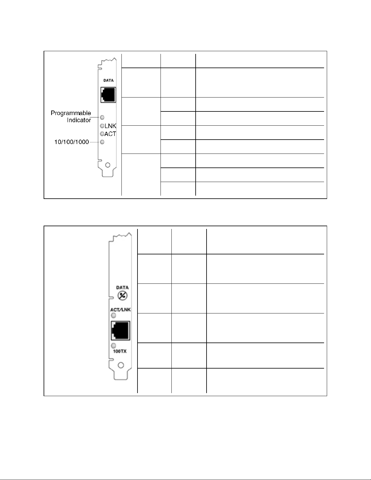
The Intel® PRO/1000 T Server Adapter has the following indicator lights:
Label Indication Meaning
Identity. Use the "Identify Adapter" button in
not labeled Flashing
Intel PROSet to control blinking. See Intel
PROSet Help for more information.
On The adapter is connected to a valid link partner.
LNK
Off No link.
On Data is being transmitted or received.
ACT
Off No data activity.
Off 10 Mbps
10/100/1000
Green 100 Mbps
Yellow 1000 Mbps
The Intel® PRO/100+, PRO/100 M, PRO/100 S , and PRO/100 VE and VM Desktop adapters and Net-
work Connections have the following indicator lights:
Label Indication Meaning
ACT/LNK On The adapter and switch are receiving
power; the cable connection between the
switch and adapter is good.
Off The adapter and switch are not receiving
power, or you have a driver configuration
problem.
Flashing The adapter is sending or receiving net-
work data. The frequency of the flashes
varies with the amount of network traffic.
100TX On Operating at 100 Mbps.
Off Operating at 10 Mbps.
Page 77
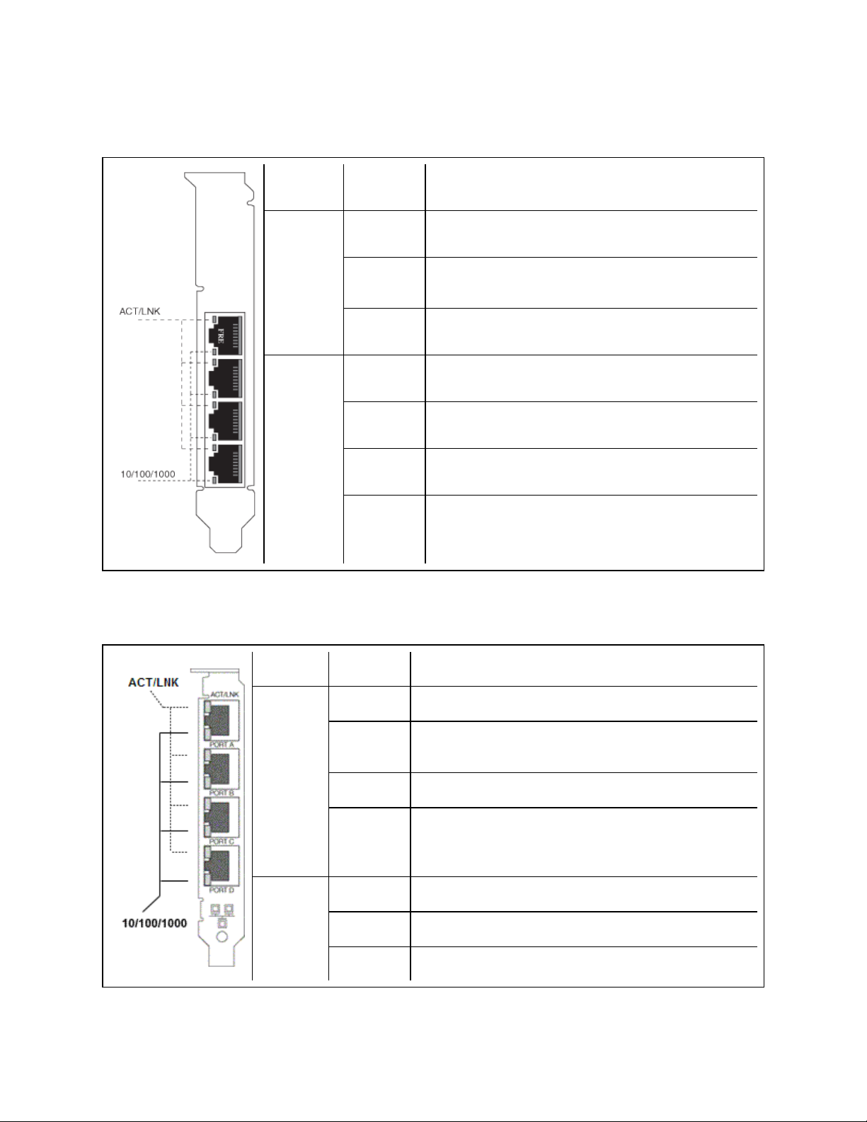
Quad Port Copper Adapters
The Intel® Ethernet Server Adapter I350-T4, I340-T4, Gigabit ET and PRO/1000 PT Quad Port LP
Server Adapters have the following indicator lights:
Label Indication Meaning
Green on The adapter is connected to a valid link partner.
ACT/LNK
10/100/
1000
The Intel® PRO/1000 MT, GT and PT Quad Port Server Adapters have the following indicator lights for
each port:
Label Indication Meaning
Green
flashing
Off No link.
Off 10 Mbps
Green 100 Mbps
Yellow 1000 Mbps
Orange
flashing
Data activity
Identity. Use the "Identify Adapter" button in Intel®
PROSet to control blinking. See Intel PROSet Help
for more information.
Top LED
ACT/LNK
Bottom
LED
10/100/
1000
Green on The port is connected to a valid link partner.
Green
flashing
Off No link.
Orange
flashing
Off 10 Mbps
Green 100 Mbps
Orange 1000 Mbps
Data activity
Identity. Use the "Identify Adapter" button in Intel
PROSet to control blinking. See Intel PROSet Help for
more information.
Page 78
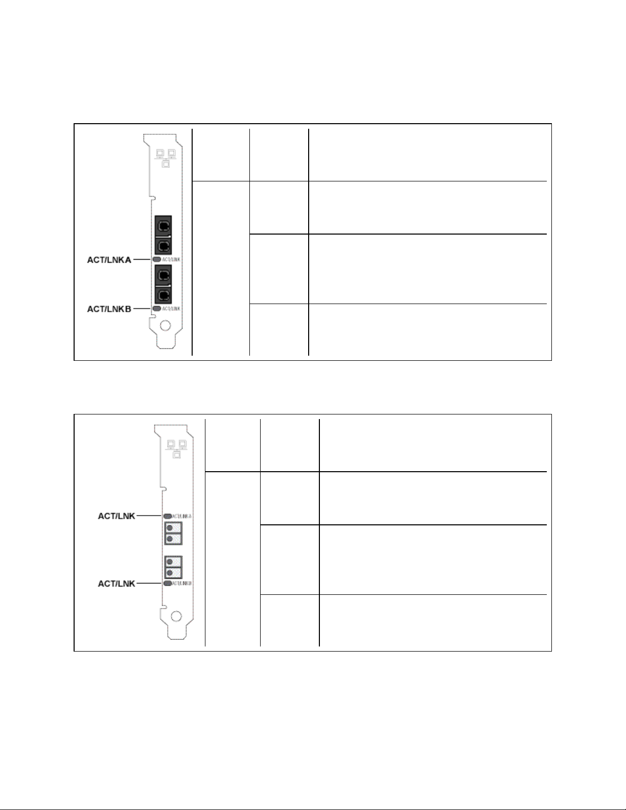
Dual Port Fiber Adapters
The Intel® 10 Gigabit XF SR Dual Port Server Adapters has the following indicator lights:
Label Indication Meaning
On The adapter is connected to a valid link partner.
Adapter is actively passing traffic.
ACT/LNK
The Intel® PRO/1000 MF, PF, and Gigabit EF Dual Port Server Adapters have the following indicator
lights for each port:
Label Indication Meaning
ACT/LNK
Blinking
Off No link.
On The adapter is connected to a valid link partner.
Blinking
Identity. Use the "Identify Adapter" button in Intel
PROSet to control blinking. See Intel PROSet Help
for more information.
Adapter is actively passing traffic.
Identity. Use the "Identify Adapter" button in Intel
PROSet to control blinking. See Intel PROSet
Help for more information.
Off No link.
Page 79

Single Port Fiber Adapters
The Intel® 10 Gigabit XF SR and LR Server Adapters has the following indicator lights:
Label Indication Meaning
On The adapter is connected to a valid link partner.
Adapter is actively passing traffic.
ACT/LNK
The Intel® PRO/1000 MF and PF Server Adapters have the following indicator lights:
Label Indication Meaning
ACT/LNK
Blinking
Off No link.
On The adapter is connected to a valid link partner.
Blinking
Identity. Use the "Identify Adapter" button in Intel
PROSet to control blinking. See Intel PROSet Help
for more information.
Adapter is actively passing traffic.
Identity. Use the "Identify Adapter" button in Intel
PROSet to control blinking. See Intel PROSet
Help for more information.
Off No link.
Page 80

The Intel® PRO/1000 XF Server Adapter has the following indicator lights:
Label Indication Meaning
On The adapter is connected to a valid link partner.
LNK
Off No link.
On Data is being transmitted or received.
ACT
Off No data activity.
not
labeled
Flashing
Identity. Use the "Identify Adapter" button in Intel
PROSet to control blinking. See Intel PROSet Help
for more information.
The Intel® PRO/1000F Server adapter has the following indicator lights:
Label Indication Meaning
TX On The adapter is sending data.
RX On The adapter is receiving data.
On
The adapter is connected to a valid link partner and
is receiving link pulses.
LNK
Off No link.
not
labeled
Flashing
Identity. Use the "Identify Adapter" button in Intel
PROSet to control blinking. See Intel PROSet Help
for more information.
Page 81

Quad Port Fiber Adapters
The Intel® Ethernet Server Adapter I340-F4 has the following indicator lights:
Label Indication Meaning
GRN=1G
Green on
Green flashing
Off No link.
The adapter is connected to a valid link partner.
Data activity
Page 82

The Intel® PRO/1000 PF Quad Port Server Adapter has the following indicator lights:
Label Indication Meaning
Green on The adapter is connected to a valid link partner.
ACT/LNK
Green flashing Data activity
Off No link.
Page 83

Regulatory Compliance Statements
Intel® FCC Class A Products
l Intel® Ethernet I/O Module XL710-Q1
l Intel® Ethernet I/O Module XL710-Q2
l Intel® Ethernet OCP Server Adapter X520-1
l Intel® Ethernet OCP Server Adapter X520-2
l Intel® Ethernet Server Bypass Adapter X540-T2
l Intel® Ethernet Converged Network Adapter X540-T1
l Intel® Ethernet Server Bypass Adapter X520-SR2
l Intel® Ethernet Converged Network Adapter X540-T2
l Intel® Ethernet Server Adapter X520-T2
l Intel® Ethernet X520 10GbE Dual Port KX4 Mezz
l Intel® 10 Gigabit AT2 Server Adapter
l Intel® 10 Gigabit SR Dual Port Express Module
l Intel® 10 Gigabit AT Server Adapter
l Intel® Gigabit ET Quad Port Mezzanine Card
l Intel® PRO/1000 MT Quad Port Server Adapter
Intel® FCC Class B Products
l Intel® Ethernet Converged Network Adapter X710-2
l Intel® Ethernet Converged Network Adapter X710-4
l Intel® Ethernet Converged Network Adapter XL710-Q1
l Intel® Ethernet Converged Network Adapter XL710-Q2
l Intel® Ethernet Server Adapter X520-1
l Intel® Ethernet Server Adapter X520-2
l Intel® Ethernet SFP+ LR Optics RMN FTLX1471
l Intel® Ethernet Converged Network Adapter X520-4
l Intel® Ethernet Converged Network Adapter X520-Q1
l Intel® 10 Gigabit AF DA Dual Port Server Adapter
l Intel® 10 Gigabit CX4 Dual Port Server Adapter
l Intel® 10 Gigabit XF SR Dual Port Server Adapter
l Intel® 10 Gigabit XF SR Server Adapter
l Intel® 10 Gigabit XF LR Server Adapter
l Intel® Ethernet Server Adapter I340-T2
l Intel® Ethernet Server Adapter I340-T4
l Intel® Ethernet Server Adapter I350-T2
l Intel® Ethernet Server Adapter I350-T4
l Intel® Ethernet Server Adapter I210-T1
Page 84

l Intel® Ethernet Server Adapter I340-F4
l Intel® Gigabit ET Dual Port Server Adapter
l Intel® Gigabit ET Quad Port Server Adapter
l Intel® Gigabit EF Dual Port Server Adapter
l Intel® Gigabit CT Desktop Adapter
l Intel® PRO/1000 MT Server Adapter
l Intel® PRO/1000 MT Dual Port Server Adapter
l Intel® PRO/1000 GT Dual Port Server Adapter
l Intel® PRO/1000 PT Server Adapter
l Intel® PRO/1000 PT Dual Port Server Adapter
l Intel® PRO/1000 GT Quad Port Server Adapter
l Intel® PRO/1000 PT Quad Port Server Adapter
l Intel® PRO/1000 PT Quad Port LP Server Adapter
l Intel® PRO/1000 GT Desktop Adapter
l Intel® PRO/1000 PT Desktop Adapter
l Intel® PRO/1000 MF Server Adapter
l Intel® PRO/1000 MF Dual Port Server Adapter
l Intel® PRO/1000 PF Server Adapter
l Intel® PRO/1000 PF Dual Port Server Adapter
l Intel® PRO/1000 PF Quad Port Server Adapter
l Intel® PRO/100 M Desktop Adapter
l Intel® PRO/100 S Desktop Adapter
l Intel® PRO/100 S Server Adapter
l Intel® PRO/100 S Dual Port Server Adapter
Safety Compliance
The following safety standards apply to all products listed above.
l UL 60950-1, 2nd Edition, 2011-12-19 (Information Technology Equipment - Safety - Part 1: General
Requirements)
l CSA C22.2 No. 60950-1-07, 2nd Edition, 2011-12 (Information Technology Equipment - Safety - Part 1:
General Requirements)
l EN 60950-1:2006/A11:2009/A1:2010/A12:2011 (European Union)
l IEC 60950-1:2005 (2nd Edition); Am 1:2009 (International)
l EU LVD Directive 2006/95/EC
EMC Compliance – The following standards may apply:
Class A products:
l FCC Part 15 – Radiated & Conducted Emissions (USA)
l CAN ICES-3(A)/NMB-3(A) – Radiated & Conducted Emissions (Canada)
l CISPR 22 – Radiated & Conducted Emissions (International)
Page 85

l EN55022: 2010 – Radiated & Conducted Emissions (European Union)
l EN55024: 2010 +A1:2001+A2:2003 – Immunity (European Union)
l EMC Directive 2004/108/EC
l VCCI (Class A)– Radiated & Conducted Emissions (Japan)
l CNS13438 – Radiated & Conducted Emissions (Taiwan)
l AS/NZS CISPR 22 – Radiated & Conducted Emissions (Australia/New Zealand)
l NRRA No. 2012-13 (2012.06.28), NRRA Notice No. 2012-14 (2012.06.28) (Korea)
Class B products:
l FCC Part 15 (Class B) – Radiated & Conducted Emissions (USA)
l CAN ICES-3(B)/NMB-3(B) – Radiated & Conducted Emissions (Canada)
l CISPR 22 – Radiated & Conducted Emissions (International)
l EN55022: 2010 – Radiated & Conducted Emissions (European Union)
l EN55024: 2010 – Immunity (European Union)
l EU – EMC Directive 2004/108/EC
l VCCI (Class B)– Radiated & Conducted Emissions (Japan) (excluding optics)
l CNS13438 (Class B)-2006 – Radiated & Conducted Emissions (Taiwan) (excluding optics)
l AS/NZS CISPR 22 – Radiated & Conducted Emissions (Australia/New Zealand)
l KN22; KN24 – Korean emissions and immunity
l NRRA No. 2012-13 (2012.06.28), NRRA Notice No. 2012-14 (2012.06.28) (Korea)
Regulatory Compliance Markings
When required these products are provided with the following Product Certification Markings:
l UL Recognition Mark for USA and Canada
l CE Mark
l EU WEEE Logo
l FCC markings
l VCCI marking
l Australian C-Tick Mark
l Korea MSIP mark
l Taiwan BSMI mark
l People's Republic of China "EFUP" mark
FCC Class A User Information
The Class A products listed above comply with Part 15 of the FCC Rules. Operation is subject to the
following two conditions:
1. This device may not cause harmful interference.
2. This device must accept any interference received, including interference that may cause undesired
operation.
Page 86

NOTE: This equipment has been tested and found to comply with the limits for a Class A digital
device, pursuant to Part 15 of the FCC rules. These limits are designed to provide reasonable protection against harmful interference when the equipment is operated in a commercial environment.
This equipment generates, uses and can radiate radio frequency energy and, if not installed and
used in accordance with the instructions, may cause harmful interference to radio communications. Operation of this equipment in a residential area is likely to cause harmful interference in which case the user will be required to correct the interference at his own expense.
CAUTION: If the device is changed or modified without permission from Intel, the user may void
his or her authority to operate the equipment.
Canadian Compliance (Industry Canada)
CAN ICES-3(A)/NMB-3(A)
VCCI Class A Statement
BSMI Class A Statement
KCC Notice Class A (Republic of Korea Only)
Page 87

BSMI Class A Notice (Taiwan)
FCC Class B User Information
This equipment has been tested and found to comply with the limits for a Class B digital device pursuant to
Part 15 of the FCC rules. These limits are designed to provide reasonable protection against harmful
interference in a residential installation. This equipment generates, uses and can radiate radio frequency
energy and, if not installed and used in accordance with the instructions, may cause harmful interference to
radio communications. However, there is no guarantee that interference will not occur in a particular
installation.
If this equipment does cause harmful interference to radio or television reception, which can be determined by
turning the equipment off and on, the user is encouraged to try to correct the interference by one or more of the
following measures:
l Reorient or relocate the receiving antenna.
l Increase the separation between the equipment and receiver.
l Connect the equipment into an outlet on a circuit different from that to which the receiver is connected.
l Consult the dealer or an experienced radio/TV technician for help.
CAUTION: If the device is changed or modified without permission from Intel, the user may void
his or her authority to operate the equipment.
NOTE: This device complies with Part 15 of the FCC Rules. Operation is subject to the following
two conditions: (1) this device may not cause harmful interference, and (2) this device must
accept any interference received, including interference that may cause undesired operation.
Electromagnetic Compatibility Notices
FCC Declaration of Conformity Statement
The following products have been tested to Comply with FCC Standards for Home or Office Use.
PRO/1000 MT, PRO/1000 PT, PRO/1000 GT, Gigabit PT, Gigabit ET, I210-T1, I340-T2/T4, I350-T2/T4,
PRO/100 M Desktop Adapter, PRO/100 S Desktop Adapter, PRO/100 S Server Adapter, and PRO/100 S
Dual Port Server Adapter
Canadian Compliance (Industry Canada)
CAN ICES-3 (B)/NMB-3 (B)
Page 88

VCCI Class B Statement (Japan)
KCC Notice Class B (Republic of Korea Only)
Page 89

EU WEEE Logo
Manufacturer Declaration European Community
Manufacturer Declaration
Intel Corporation declares that the equipment described in this document is in conformance with the
requirements of the European Council Directive listed below:
l Low Voltage Directive 2006/95/EC
l EMC Directive2004/108/EC
l RoHS Directive 2011/65/EU
These products follow the provisions of the European Directive 1999/5/EC.
Page 90

Dette produkt er i overensstemmelse med det europæiske direktiv 1999/5/EC.
Dit product is in navolging van de bepalingen van Europees Directief 1999/5/EC.
Tämä tuote noudattaa EU-direktiivin 1999/5/EC määräyksiä.
Ce produit est conforme aux exigences de la Directive Européenne 1999/5/EC.
Dieses Produkt entspricht den Bestimmungen der Europäischen Richtlinie 1999/5/EC.
Þessi vara stenst reglugerð Evrópska Efnahags Bandalagsins númer 1999/5/EC.
Questo prodotto è conforme alla Direttiva Europea 1999/5/EC.
Dette produktet er i henhold til bestemmelsene i det europeiske direktivet 1999/5/EC.
Este produto cumpre com as normas da Diretiva Européia 1999/5/EC.
Este producto cumple con las normas del Directivo Europeo 1999/5/EC.
Denna produkt har tillverkats i enlighet med EG-direktiv 1999/5/EC.
This declaration is based upon compliance of the Class A products listed above to the following standards:
EN 55022:2010 (CISPR 22 Class A) RF Emissions Control.
EN 55024:2010 (CISPR 24) Immunity to Electromagnetic Disturbance.
EN 60950-1:2006/A11:2009A1:2010/A12:2011 Information Technology Equipment- Safety-Part 1: General
Requirements.
EN 50581:2012 - Technical documentation for the assessment of electrical and electronic products with
respect to the restriction of hazardous substances.
This declaration is based upon compliance of the Class B products listed above to the following standards:
EN 55022:2010 (CISPR 22 Class B) RF Emissions Control.
EN 55024:2010 (CISPR 24) Immunity to Electromagnetic Disturbance.
EN 60950-1:2006/A11:2009/A1:2010/A12:2011 Information Technology Equipment- Safety-Part 1: General
Requirements.
EN 50581:2012 - Technical documentation for the assessment of electrical and electronic products with
respect to the restriction of hazardous substances.
WARNING: In a domestic environment, Class A products may cause radio interference, in which
case the user may be required to take adequate measures.
Responsible Party
Intel Corporation, Mailstop JF3-446
5200 N.E. Elam Young Parkway
Hillsboro, OR 97124-6497
Phone 1-800-628-8686
Page 91

China RoHS Declaration
Class 1 Laser Products
Server adapters listed above may contain laser devices for communication use. These devices are compliant
with the requirements for Class 1 Laser Products and are safe in the intended use. In normal operation the
output of these laser devices does not exceed the exposure limit of the eye and cannot cause harm.
For continued safe operation in case of an abnormal circumstance, always have the provided laser connector
cover in place or a compatible fiber optics cable properly connected when power is available to the product.
The Laser device must be factory serviced ONLY by the responsible manufacturer! NO adjustments, service
or maintenance is to be performed otherwise.
CAUTION: Use of controls or adjustments or performance of procedures other than those
specified herein may result in hazardous radiation exposure.
These Class 1 Laser devices:
Comply with FDA/CDRH per CFR21, subchapter J.
Comply with IEC 60825-1:2007
End-of-Life / Product Recycling
Product recycling and end-of-life take-back systems and requirements vary by country.
Contact the retailer or distributor of this product for information about product recycling and/or take-back.
Page 92

Legal Disclaimers
INTEL SOFTWARE LICENSE AGREEMENT
IMPORTANT - READ BEFORE COPYING, INSTALLING OR USING.
Do not copy, install, or use this software and any associated materials (collectively, the "Software")
provided under this license agreement ("Agreement") until you have carefully read the following
terms and conditions.
By copying, installing, or otherwise using the Software, you agree to be bound by the terms of this
Agreement. If you do not agree to the terms of this Agreement, do not copy, install, or use the
Software.
LICENSES
Please Note:
l If you are a network or system administrator, the "Site License" below shall apply to you.
l If you are an end user, the "Single User License" shall apply to you.
l If you are an original equipment manufacturer (OEM), the "OEM License" shall apply to you.
SITE LICENSE: You may copy the Software onto your organization's computers for your organization's use,
and you may make a reasonable number of back-up copies of the Software, subject to these conditions:
1. This Software is licensed for use only in conjunction with (a) physical Intel component
products, and (b) virtual ("emulated") devices designed to appear as Intel component
products to a Guest operating system running within the context of a virtual machine. Any
other use of the Software, including but not limited to use with non-Intel component
products, is not licensed hereunder.
2. Subject to all of the terms and conditions of this Agreement, Intel Corporation ("Intel") grants to you a
non-exclusive, non-assignable, copyright license to use the Software.
3. You may not copy, modify, rent, sell, distribute, or transfer any part of the Software except as provided
in this Agreement, and you agree to prevent unauthorized copying of the Software.
4. You may not reverse engineer, decompile, or disassemble the Software.
5. The Software may include portions offered on terms differing from those set out here, as set out in a
license accompanying those portions.
SINGLE USER LICENSE: You may copy the Software onto a single computer for your personal use, and
you may make one back-up copy of the Software, subject to these conditions:
1. This Software is licensed for use only in conjunction with (a) physical Intel component
products, and (b) virtual ("emulated") devices designed to appear as Intel component
products to a Guest operating system running within the context of a virtual machine. Any
other use of the Software, including but not limited to use with non-Intel component
products, is not licensed hereunder.
2. Subject to all of the terms and conditions of this Agreement, Intel Corporation ("Intel") grants to you a
non-exclusive, non-assignable, copyright license to use the Software.
3. You may not copy, modify, rent, sell, distribute, or transfer any part of the Software except as provided
in this Agreement, and you agree to prevent unauthorized copying of the Software.
Page 93

4. You may not reverse engineer, decompile, or disassemble the Software.
5. The Software may include portions offered on terms differing from those set out here, as set out in a
license accompanying those portions.
OEM LICENSE: You may reproduce and distribute the Software only as an integral part of or incorporated in
your product, as a standalone Software maintenance update for existing end users of your products, excluding
any other standalone products, or as a component of a larger Software distribution, including but not limited to
the distribution of an installation image or a Guest Virtual Machine image, subject to these conditions:
1. This Software is licensed for use only in conjunction with (a) physical Intel component
products, and (b) virtual ("emulated") devices designed to appear as Intel component
products to a Guest operating system running within the context of a virtual machine. Any
other use of the Software, including but not limited to use with non-Intel component
products, is not licensed hereunder.
2. Subject to all of the terms and conditions of this Agreement, Intel Corporation ("Intel") grants to you a
non-exclusive, non-assignable, copyright license to use the Software.
3. You may not copy, modify, rent, sell, distribute or transfer any part of the Software except as provided
in this Agreement, and you agree to prevent unauthorized copying of the Software.
4. You may not reverse engineer, decompile, or disassemble the Software.
5. You may only distribute the Software to your customers pursuant to a written license agreement. Such
license agreement may be a "break-the-seal" license agreement. At a minimum such license shall safeguard Intel's ownership rights to the Software.
6. You may not distribute, sublicense or transfer the Source Code form of any components of the Software and derivatives thereof to any third party without the express written consent of Intel.
7. The Software may include portions offered on terms differing from those set out here, as set out in a
license accompanying those portions.
LICENSE RESTRICTIONS. You may NOT: (i) use or copy the Software except as provided in this
Agreement; (ii) rent or lease the Software to any third party; (iii) assign this Agreement or transfer the Software
without the express written consent of Intel; (iv) modify, adapt, or translate the Software in whole or in part
except as provided in this Agreement; (v) reverse engineer, decompile, or disassemble the Software; (vi)
attempt to modify or tamper with the normal function of a license manager that regulates usage of the
Software; (vii) distribute, sublicense or transfer the Source Code form of any components of the Software and
derivatives thereof to any third party without the express written consent of Intel; (viii) permit, authorize,
license or sublicense any third party to view or use the Source Code; (ix) modify or distribute the Source Code
or Software so that any part of it becomes subject to an Excluded License. (An "Excluded License" is one that
requires, as a condition of use, modification, or distribution, that (a) the code be disclosed or distributed in
source code form; or (b) others have the right to modify it.); (x) use or include the Source Code or Software in
deceptive, malicious or unlawful programs.
NO OTHER RIGHTS. No rights or licenses are granted by Intel to you, expressly or by implication, with
respect to any proprietary information or patent, copyright, mask work, trademark, trade secret, or other
intellectual property right owned or controlled by Intel, except as expressly provided in this Agreement. Except
as expressly provided herein, no license or right is granted to you directly or by implication, inducement,
estoppel, or otherwise. Specifically, Intel grants no express or implied right to you under Intel patents,
copyrights, trademarks, or other intellectual property rights.
Page 94

OWNERSHIP OF SOFTWARE AND COPYRIGHTS. The Software is licensed, not sold. Title to all copies
of the Software remains with Intel. The Software is copyrighted and protected by the laws of the United States
and other countries and international treaty provisions. You may not remove any copyright notices from the
Software. You agree to prevent any unauthorized copying of the Software. Intel may make changes to the
Software, or to items referenced therein, at any time without notice, but is not obligated to support or update
the Software.
ADDITIONAL TERMS FOR PRE-RELEASE SOFTWARE. If the Software you are installing or using under
this Agreement is pre-commercial release or is labeled or otherwise represented as "alpha-" or "beta-"
versions of the Software ("pre-release Software"), then the following terms apply. To the extent that any
provision in this Section conflicts with any other term(s) or condition(s) in this Agreement with respect to prerelease Software, this Section shall supersede the other term(s) or condition(s), but only to the extent
necessary to resolve the conflict. You understand and acknowledge that the Software is pre-release
Software, does not represent the final Software from Intel, and may contain errors and other problems that
could cause data loss, system failures, or other errors. The pre-release Software is provided to you "as-is" and
Intel disclaims any warranty or liability to you for any damages that arise out of the use of the pre-release
Software. You acknowledge that Intel has not promised that pre-release Software will be released in the
future, that Intel has no express or implied obligation to you to release the pre-release Software and that Intel
may not introduce Software that is compatible with the pre-release Software. You acknowledge that the
entirety of any research or development you perform that is related to the pre-release Software or to any
product making use of or associated with the pre-release Software is done at your own risk. If Intel has
provided you with pre-release Software pursuant to a separate written agreement, your use of the pre-release
Software is also governed by such agreement.
LIMITED MEDIA WARRANTY. If the Software has been delivered by Intel on physical media, Intel
warrants the media to be free from material physical defects for a period of ninety days after delivery by Intel.
If such a defect is found, return the media to Intel for replacement or alternate delivery of the Software as Intel
may select.
EXCLUSION OF OTHER WARRANTIES. EXCEPT AS PROVIDED ABOVE, THE SOFTWARE IS
PROVIDED "AS IS" WITHOUT ANY EXPRESS OR IMPLIED WARRANTY OF ANY KIND
INCLUDING WARRANTIES OF MERCHANTABILITY, NONINFRINGEMENT, OR FITNESS FOR A
PARTICULAR PURPOSE. Intel does not warrant or assume responsibility for the accuracy or completeness
of any information, text, graphics, links, or other items contained within the Software.
LIMITATION OF LIABILITY. IN NO EVENT SHALL INTEL OR ITS SUPPLIERS BE LIABLE FOR
ANY DAMAGES WHATSOEVER (INCLUDING, WITHOUT LIMITATION, LOST PROFITS, BUSINESS
INTERRUPTION, OR LOST INFORMATION) ARISING OUT OF THE USE OF OR INABILITY TO USE
THE SOFTWARE, EVEN IF INTEL HAS BEEN ADVISED OF THE POSSIBILITY OF SUCH
DAMAGES. SOME JURISDICTIONS PROHIBIT EXCLUSION OR LIMITATION OF LIABILITY FOR
IMPLIED WARRANTIES OR CONSEQUENTIAL OR INCIDENTAL DAMAGES, SO THE ABOVE
LIMITATION MAY NOT APPLY TO YOU. YOU MAY ALSO HAVE OTHER LEGAL RIGHTS THAT
VARY FROM JURISDICTION TO JURISDICTION. In the event that you use the Software in conjunction
with a virtual ("emulated") device designed to appear as an Intel component product, you acknowledge that
Intel is neither the author nor the creator of the virtual ("emulated") device. You understand and acknowledge
that Intel makes no representations about the correct operation of the Software when used with a virtual
("emulated") device, that Intel did not design the Software to operate in conjunction with the virtual
("emulated") device, and that the Software may not be capable of correct operation in conjunction with the
virtual ("emulated") device. You agree to assume the risk that the Software may not operate properly in
conjunction with the virtual ("emulated") device. You agree to indemnify and hold Intel and its officers,
subsidiaries and affiliates harmless against all claims, costs, damages, and expenses, and reasonable
Page 95

attorney fees arising out of, directly or indirectly, any claim of product liability, personal injury or death
associated with the use of the Software in conjunction with the virtual ("emulated") device, even if such claim
alleges that Intel was negligent regarding the design or manufacture of the Software.
UNAUTHORIZED USE.THE SOFTWARE IS NOT DESIGNED, INTENDED, OR AUTHORIZED FOR
USE IN ANY TYPE OF SYSTEM OR APPLICATION IN WHICH THE FAILURE OF THE SOFTWARE
COULD CREATE A SITUATION WHERE PERSONAL INJURY OR DEATH MAY OCCUR (E.G
MEDICAL SYSTEMS, LIFE SUSTAINING OR LIFE SAVING SYSTEMS). If you use the Software for any
such unintended or unauthorized use, you shall indemnify and hold Intel and its officers, subsidiaries and
affiliates harmless against all claims, costs, damages, and expenses, and reasonable attorney fees arising
out of, directly or indirectly, any claim of product liability, personal injury or death associated with such
unintended or unauthorized use, even if such claim alleges that Intel was negligent regarding the design or
manufacture of the part.
TERMINATION OF THIS AGREEMENT. Intel may terminate this Agreement at any time if you violate its
terms. Upon termination, you will immediately destroy the Software or return all copies of the Software to
Intel.
APPLICABLE LAWS. Claims arising under this Agreement shall be governed by the laws of the State of
California, without regard to principles of conflict of laws. You agree that the terms of the United Nations
Convention on Contracts for the Sale of Goods do not apply to this Agreement. You may not export the
Software in violation of applicable export laws and regulations. Intel is not obligated under any other
agreements unless they are in writing and signed by an authorized representative of Intel.
GOVERNMENT RESTRICTED RIGHTS. The enclosed Software and documentation were developed at
private expense, and are provided with "RESTRICTED RIGHTS." Use, duplication, or disclosure by the
Government is subject to restrictions as set forth in FAR 52.227-14 and DFARS 252.227-7013 et seq. or its
successor. The use of this product by the Government constitutes acknowledgement of Intel’s proprietary
rights in the Software. Contractor or Manufacturer is Intel.
LANGUAGE; TRANSLATIONS. In the event that the English language version of this Agreement is
accompanied by any other version translated into any other language, such translated version is provided for
convenience purposes only and the English language version shall control.
Copyright and Legal Disclaimers
Copyright © 2002 - 2015 Intel Corporation. All rights reserved.
Intel Corporation, 5200 N.E. Elam Young Parkway, Hillsboro, OR 97124-6497 USA
Intel Corporation assumes no responsibility for errors or omissions in this document. Nor does Intel make any
commitment to update the information contained herein.
Intel, Itanium, and Pentium are trademarks of Intel Corporation in the U.S. and other countries.
*Other names and brands may be claimed as the property of others.
Limited Lifetime Hardware Warranty
Intel warrants to the original owner that the adapter product delivered in this package will be free from defects
in material and workmanship. This warranty does not cover the adapter product if it is damaged in the process
of being installed or improperly used.
Page 96

THE ABOVE WARRANTY IS IN LIEU OF ANY OTHER WARRANTY, WHETHER EXPRESS, IMPLIED
OR STATUTORY, INCLUDING BUT NOT LIMITED TO ANY WARRANTY OF NONINFRINGEMENT OF
INTELLECTUAL PROPERTY, MERCHANTABILITY, FITNESS FOR A PARTICULAR PURPOSE
ARISING OUT OF ANY PROPOSAL, SPECIFICATION, OR SAMPLE.
This warranty does not cover replacement of adapter products damaged by abuse, accident, misuse, neglect,
alteration, repair, disaster, improper installation, or improper testing. If the adapter product is found to be
defective, Intel, at its option, will replace or repair the hardware product at no charge except as set forth below,
or refund your purchase price provided that you deliver the adapter product along with a Return Material
Authorization(RMA) number (see below), along with proof of purchase (if not registered), either to the dealer
from whom you purchased it or to Intel with an explanation of any deficiency. If you ship the adapter product,
you must assume the risk of damage or loss in transit. You must use the original container (or the equivalent)
and pay the shipping charge.
Intel may replace or repair the adapter product with either new or reconditioned parts, and any adapter product,
or part thereof replaced by Intel becomes Intel's property. Repaired or replaced adapter products will be
returned to you at the same revision level as received or higher, at Intel's option. Intel reserves the right to
replace discontinued adapter products with an equivalent current generation adapter product.
Returning a defective product
From North America:
Before returning any adapter product, contact Intel Customer Support and obtain a Return Material
Authorization (RMA) number by calling +1 916-377-7000.
If the Customer Support Group verifies that the adapter product is defective, they will have the RMA
department issue you an RMA number to place on the outer package of the adapter product. Intel cannot
accept any product without an RMA number on the package.
All other locations:
Return the adapter product to the place of purchase for a refund or replacement.
Intel Adapter Money-back Guarantee (North America Only)
Intel wants you to be completely satisfied with the Intel adapter product that you have purchased. Any time
within ninety (90) days of purchase, you may return your Intel adapter to the original place of purchase for a full
refund of the purchase price from your dealer. Resellers and distributors, respectively, accepting returns and
refunding money back to their customers may return Intel adapters to their original place of purchase. Intel
guarantees that it will accept returns under this policy and refund the original purchase price to customers
purchasing directly from Intel.
Limitation of Liability and Remedies
INTEL'S SOLE LIABILITY HEREUNDER SHALL BE LIMITED TO DIRECT, OBJECTIVELY
MEASURABLE DAMAGES. IN NO EVENT SHALL INTEL HAVE ANY LIABILITY FOR ANY INDIRECT
OR SPECULATIVE DAMAGES (INCLUDING, WITHOUT LIMITING THE FOREGOING,
CONSEQUENTIAL, INCIDENTAL, AND SPECIAL DAMAGES) INCLUDING, BUT NOT LIMITED TO,
INFRINGEMENT OF INTELLECTUAL PROPERTY, REPROCUREMENT COSTS, LOSS OF USE,
BUSINESS INTERRUPTIONS, LOSS OF GOODWILL, AND LOSS OF PROFITS, WHETHER ANY
SUCH DAMAGES ARISE OUT OF CONTRACT NEGLIGENCE, TORT, OR UNDER ANY WARRANTY,
IRRESPECTIVE OF WHETHER INTEL HAS ADVANCE NOTICE OF THE POSSIBILITY OF ANY SUCH
DAMAGES. NOTWITHSTANDING THE FOREGOING, INTEL'S TOTAL LIABILITY FOR ALL CLAIMS
UNDER THIS AGREEMENT SHALL NOT EXCEED THE PRICE PAID FOR THE PRODUCT. THESE
Page 97

LIMITATIONS ON POTENTIAL LIABILITIES WERE AN ESSENTIAL ELEMENT IN SETTING THE
PRODUCT PRICE. INTEL NEITHER ASSUMES NOR AUTHORIZES ANYONE TO ASSUME FOR IT
ANY OTHER LIABILITIES.
Some states do not allow the exclusion or limitation of incidental or consequential damages, so the above
limitations may not apply to you.
Critical Control Applications: Intel specifically disclaims liability for use of the adapter product in critical
control applications (including, for example only, safety or health care control systems, nuclear energy control
systems, or air or ground traffic control systems) by Licensee or Sublicensees, and such use is entirely at the
user's risk. Licensee agrees to defend, indemnify, and hold Intel harmless from and against any and all claims
arising out of use of the adapter product in such applications by Licensee or Sublicensees.
Software: Software provided with the adapter product is not covered under the hardware warranty described
above. See the applicable software license agreement which shipped with the adapter product for details on
any software warranty.
Note: If you are a consumer under the Australian Consumer Law, this warranty does not apply to you. Please
visit Australian Limited Lifetime Hardware Warranty to view the limited warranty which is applicable to
Australian consumers.
Customer Support
Intel support is available on the web or by phone. Support offers the most up-to-date information about Intel
products, including installation instructions, troubleshooting tips, and general product information.
Web and Internet Sites
Support: http://www.intel.com/support
Corporate Site for Network Products: http://www.intel.com/products/ethernet/overview.htm
 Loading...