

Page 1
Thank you for buying an Intel® Server System. The following information will help you
assemble your Intel® Server System and install components.
If you are not familiar with ESD [Electrostatic Discharge] procedures used during
system integration, see the complete ESD procedures described in your Service Guide.
This guide and other supporting documents are located on the web at:
http://www.intel.com/support.
Intel® Server System P4000CP Family
Quick Installation User's Guide
G43150-001
Page 2

(This page is intentionally left blank.)
Page 3

i
Table of Contents
General Installation Process ........................................................................................................ 3
System Overview .............................................................................................................................. 1
Preparing the System ....................................................................................................... 3
Remove the Side Cover ................................................................................................... 3
Remove the Air Duct ......................................................................................................... 3
Install the Processor(s) .................................................................................................... 3
Install Active Heat Sink(s) ............................................................................................. 4
Install DIMM Memory Modules ..................................................................................... 5
Install Tool-less CD-ROM or DVD-ROM Drive ........................................................ 5
Install Hard Drive ................................................................................................................. 6
Install PCI Card Assembly ............................................................................................... 7
Install Expander Card (optional) .................................................................................. 8
Install Alternate Serial Port (optional) ..................................................................... 8
Install Intel® Remote Management Module 4 NIC (optional) ....................... 8
Install Intel® RAID Smart Battery (optional) ......................................................... 9
Install Second Power Supply Module (optional) ................................................. 9
Rack Mount Configuration (optional) ....................................................................... 9
Install Feet (pedestal only) ............................................................................................ 9
Install Air Duct ................................................................................................................... 10
Install Side Cover .............................................................................................................. 10
Finishing Up ......................................................................................................................... 10
Install Software ................................................................................................................. 10
HDD Cage Cable Connection ...................................................................................... 11
Front Panel Controls and Indicators ...................................................................... 12
Cable Routing Diagram .................................................................................................. 12
Reference ............................................................................................................................................ 11
Page 4
ii
Warning
Read all caution and safety
statements in this document
before performing any of the
instructions. Also see the Intel®
Server Board and Server Chassis
Safety Information document at:
http://www.intel.com/support/
motherboards/server/sb/cs-010770
.htm for complete safety information.
Warning
Installation and service
of this product to be
performed only by
qualified service personnel
to avoid risk of injury from
electrical shock or energy
hazard.
Caution
Observe normal ESD
[Electrostatic Discharge]
procedures during system
integration to avoid possible
damage to server board and/or
other components.
Tools Required
Anti-static
wrist strap
Phillips*
screwdriver
Flat Blade
screwdriver
Intel is a registered trademark of Intel Corporation or its subsidiaries in the United States and other countries. *Other names and brands may be claimed as the
property of others. Copyright © 2011, Intel Corporation. All rights reserved.
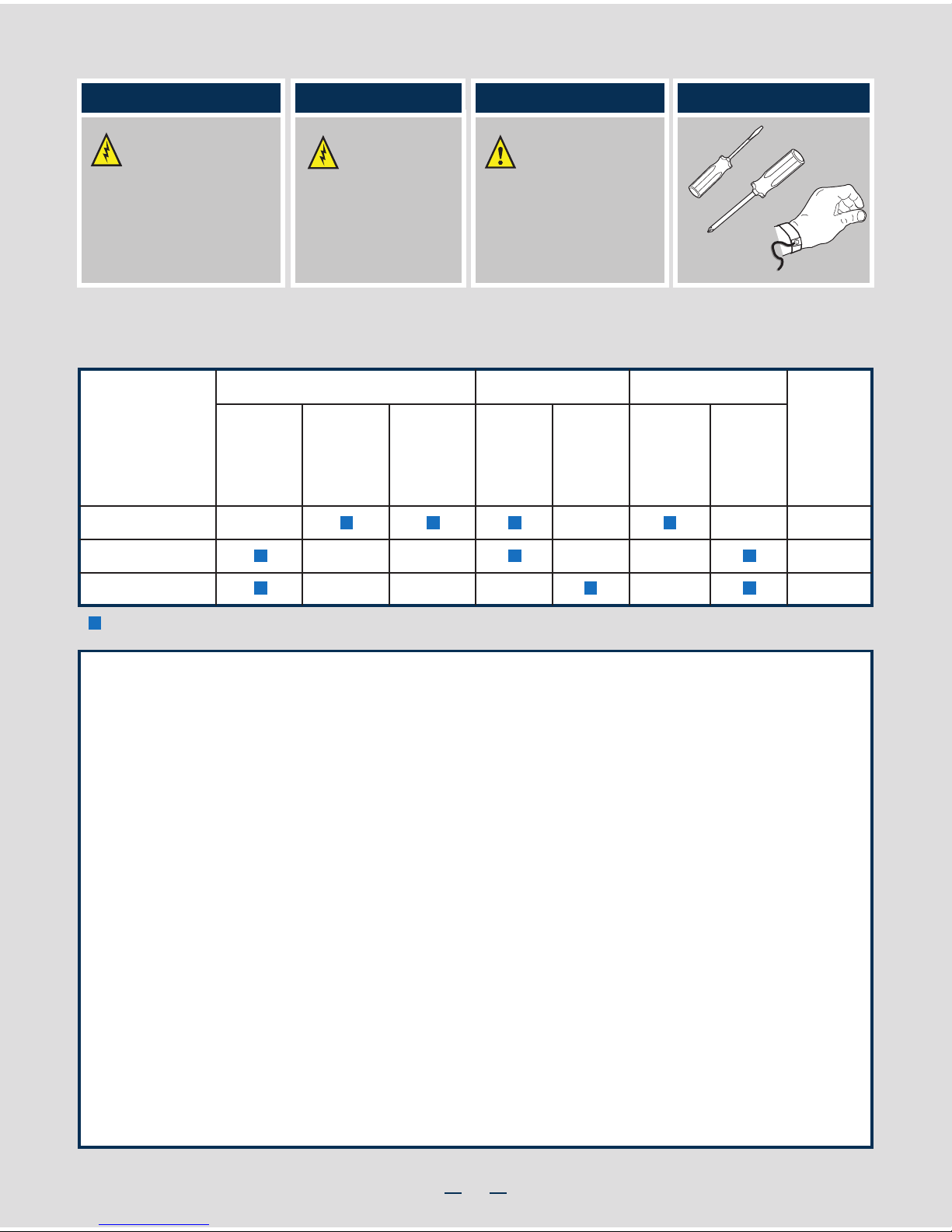
Thermal Operation and Configuration Requirements
To keep the system operating within supported maximum thermal limits, the system must meet the following operating and
configuration guidelines:
Intel® Server System P4000CP Family Product Configuration
= Configuration Feature
8 x 3.5"
Hot Swap
8 x 2.5"
Hot Swap
Hard DriveSystem Fan
One
Fixed
550W
Two
Hot Swap
750W
RKSATA8
RKSATA8
RKSAS8
Power Supply
P4308CP4MHEN
P4308CP4MHGC
P4208CP4MHGC
Intel® Server
System
Intel®
RAID
C600
Upgrade
Key
Five
Hot Swap
System
Fans
(80 x 38 mm)
One
Fixed
PCI Zone
Fan
(120 x 38 mm)
One
Fixed
CPU Zone
Fan
(120 x 38 mm)
Thermal Operation and Configuration Requirements
To keep the system operating within supported maximum thermal limits, the system must meet the following operating and configuration
guidelines:
• Ambient in-let temperature cannot exceed 35º C and should not remain at this maximum level for long periods of time. Doing so
may affect long term reliability of the system.
• The CPU-1 processor and CPU heatsink must be installed.
• DIMM Population on CPU-1: Install DIMMs in order; Channels A, B, C, and D. Start with 1st DIMM slot (blue) on each
channel.
• DIMM Population on CPU-2: Install DIMMs in order; Channels E, F, G, and H. Start with 1st DIMM slot (blue) on each
channel.
• All hard drive bays must be populated. Hard drive carriers either can be populated with a hard drive or supplied drive blank.
• The air duct must be installed at all times.
• In single power supply configurations, the second power supply bay must have the supplied filler blank installed at all times.
• The system top-cover must be installed at all times.
Page 5
1
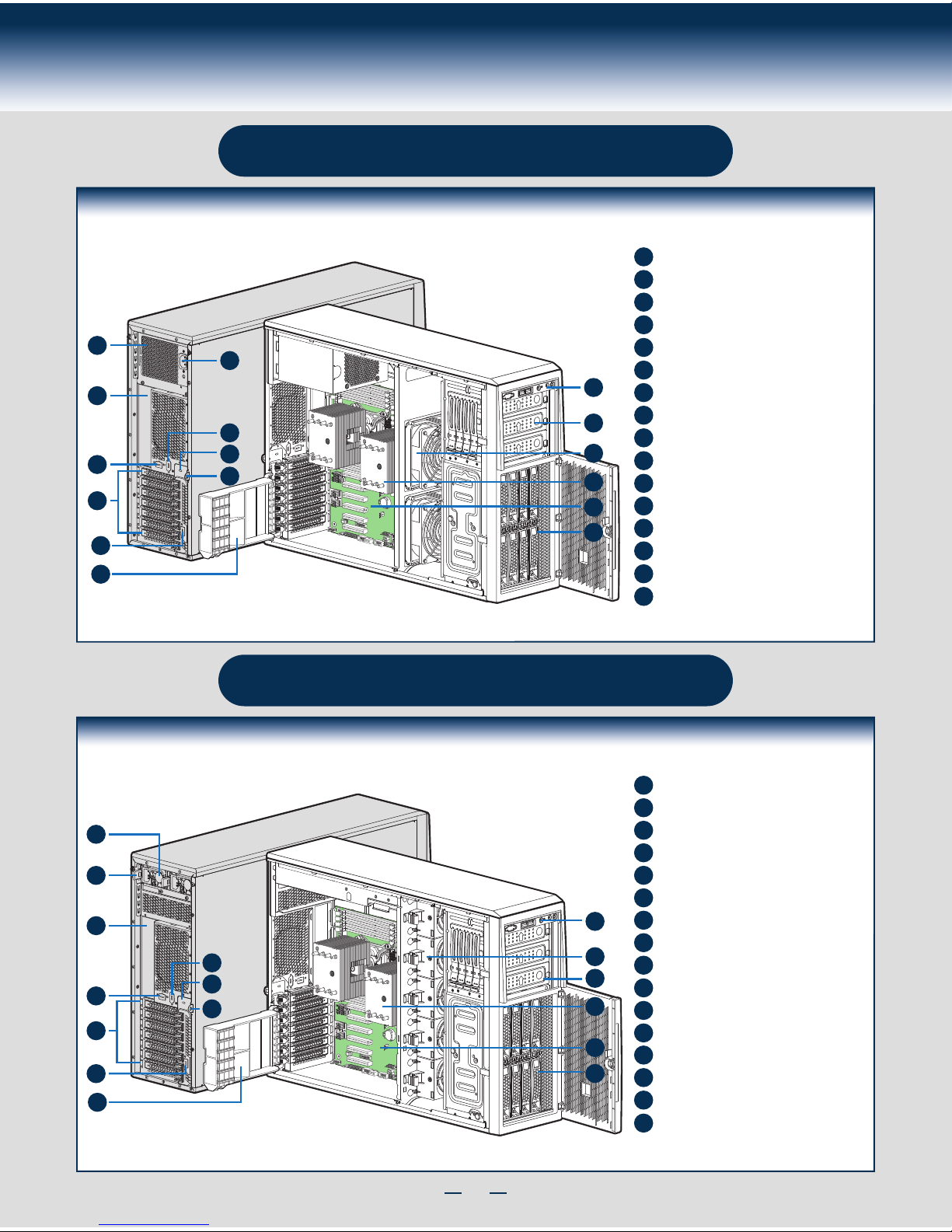
System Overview
Intel® Server System P4308CP4MHGC
B
A
F
G
H
C
D
E
I
K
J
L
M
O
N
P
System Features and Components
750-W Hot Swap Power Supply (Two)
I/O Ports
A Kensington* Cable Lock Mounting Hole
PCI Add-in Board Slot Covers
AC Input Power Connector (Two)
Alternate Serial Port Knockout
Alternate RMM4 Knockout
Padlock Loop
Alternate RMM4 Knockout
Hot-swap System Fan
Heatsink
A
B
C
D
E
F
G
H
I
J
K
L
M
N
O
8 x 3.5" Hot-swap HDD Cage
Front Control Panel
5.25" Peripheral Bays
Server Board
P
PCI retainer
NOTE: Airduct is not shown.
Intel® Server System P4308CP4MHEN
A
E
F
G
H
B
C
D
I
P
J
K
L
N
M
O
System Features and Components
550-W Fixed Power Supply
I/O Ports
A Kensington* Cable Lock Mounting Hole
PCI Add-in Board Slot Covers
AC Input Power Connector
Serial Port Knockout
Alternate RMM4 Knockout
Padlock Loop
Alternate RMM4 Knockout
Front Control Panel
5.25" Peripheral Bays
Fixed System Fan
PCI retainer
A
B
C
D
E
F
G
H
I
J
K
L
P
Heatsink
Server Board
M
N
8 x 3.5" Hot-swap HDD Cage
O
NOTE: Airduct is not shown.
Page 6
2
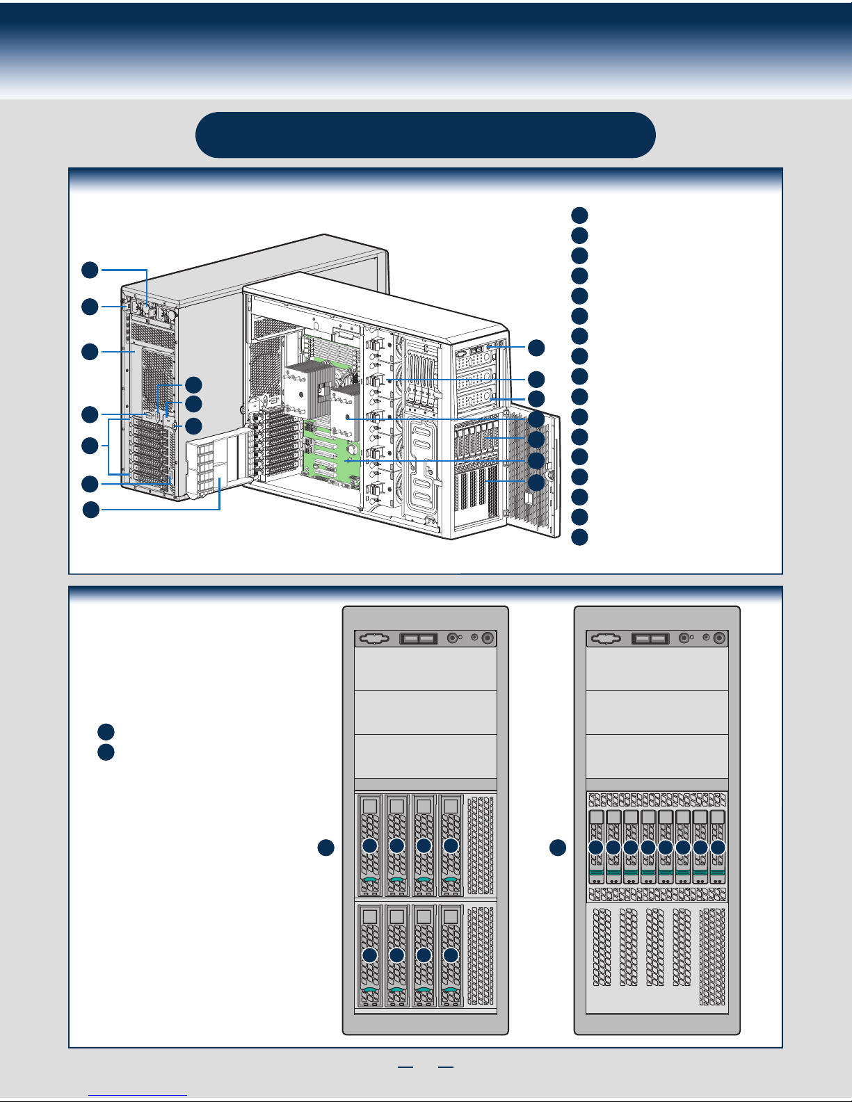
System Overview
8 x 3.5" Hot-swap HDD Cage
0123
4567
01234567
Hot Swap Hard Drive
Bay Options and
HDD Numbering
8 x 3.5" Hot-Swap Drive Cage
8 x 2.5" Hot-Swap Drive Cage
A
A
B
B
Intel® Server System P4208CP4MHGC
B
A
F
G
H
C
D
E
I
K
J
L
M
N
P
O
Q
System Features and Components
750-W Hot Swap Power Supply (Two)
I/O Ports
A Kensington* Cable Lock Mounting Hole
PCI Add-in Board Slot Covers
AC Input Power Connector (Two)
Alternate Serial Port Knockout
Alternate RMM4 Knockout
Padlock Loop
Alternate RMM4 Knockout
Hot-swap System Fan
Heatsink
A
B
C
D
E
F
G
H
I
J
K
L
M
N
O
Front Control Panel
5.25" Peripheral Bays
8 x 2.5" Hot-swap HDD Cage
Server Board
P
EMI Filler
NOTE: Airduct is not shown.
Q
PCI retainer
Page 7

3
General Installation Process
The installation instructions in this section are for general components of Intel® Server System
P4000MCP family, but the illustrations are based on the Intel® Server System P4308CP4MHEN.
Minimum Hardware Requirements
■ Processor
■ Heat Sink
■ Memory
■ Hard Disk Drives
■ Power
■ Air Duct
To avoid integration difficulties and possible damage to your system,
make sure you have components from each category below.
1
Preparing the System
Observe normal ESD (Electrostatic Discharge) procedures.
Place your Intel® Server System on a flat anti-static
surface to perform the following integration procedures.
Observe ESD procedures before reaching inside to make
server board connections or install components.
A
3
Remove the Air Duct
A
Remove the air duct.
4
Remove Processor Heatsink(s)
The heatsink is attached to the server
board / processor socket with captive fasteners.
Lift the heatsink straight up.
A
C
Proceed to screw 2 and loosen it by
giving it two rotations and stop.
Similarly, loosen screws 3 and 4.
Repeat steps A and B by giving each
screw two rotations each time until
all screws are loosened.
Using a #2 Phillips* screwdriver,
start with screw 1 and loosen it
by giving it two rotations and stop.
(IMPORTANT: Do not fully loosen.)
B
CAUTION: The heatsink has thermal interface material (TIM) on
the underside of it. Use caution so that you do not damage the
thermal interface material. Use gloves to avoid sharp edges.
Using a #2 Phillips* screwdriver, loosen the four
screws located on the heatsink corners in a
diagonal manner using the following procedure:
OPEN 1st
CLOSE 1st
NO CP U
Processor
Socket
2
3
1
4
A
B
C
5
Install the Processor(s)
CLOSE 1s t
OPEN 1st
REMOVE
REMOVE
OPEN 1st
A
NO CPU
OPEN 1st
CLOSE 1s t
B
NO CPU
A. Open the Socket Lever
A
B
Repeat step A to release
the lever on the other
side.
Push down the lever
handle on the OPEN 1st
side and away from the
socket to release it.
NOTE: Release
the levers in the
order as shown.
Remove the Side Cover
B
Remove the screws.
A
Note:
A non-skid surface or a
stop behind the chassis
may be needed to prevent
the chassis from sliding on
your work surface.
Slide the side cover back and lift
the cover outward to remove it.
A
A
B
2
Page 8

4
General Installation Process
6
Install Heat Sink(s)
Get heat sink from the shipping position.
A
Remove the protective film on the TIM if present.
E
D
B
C
Securely re-tighten each fastener again in the same order as performed in Step E.
Using a #2 Phillips* screwdriver, finger-tighten each fastener diagonally,
according to the numbers shown.
Align heat sink fins to the front and back of the chassis for correct airflow.
Airflow goes from front-to-back of chassis.
The heat sink has four captive fasteners and should be tightened using the following procedure:
CAUTION: The heat sink has thermal interface
material (TIM) on the underside of it. Use caution so
that you do not damage the thermal interface material.
Use gloves to avoid sharp edges.
OPEN 1st
CLOSE 1st
C
TIM
Processor
Socket
AIRFLOW
B
2
3
1
4
Chassis Front
D
E
CAUTION:
Do not
over-tighten
fasteners.
Save the
protective
cover.
Install the Processor(s) ... continued
D. Remove the Cover
Press the cover to
remove it.
Carefully lower the load plate over
the processor.
E. Close the Load Plate
Push down on the locking lever on the CLOSE 1st side.
F. Latch the Locking Lever
A
B
Slide the tip of the lever under the notch in the load plate. Make sure
the load plate tab engages under the socket lever when fully closed.
C
Repeat the steps to latch the locking lever on the other side.
OPEN 1st
CLOSE 1s t
CLOSE 1st
B
A
OPEN 1st
CLOSE 1s t
C
NOTE: Latch the levers in
the order as shown.
Install the Processor(s) ... continued
B
OPEN 1st
CLOSE 1s t
A
NO CPU
B. Open the Load Plate
A
B
Open the load plate all the way.
Press the locking lever slightly to raise the
load plate.
B
C
C. Install the Processor
Take the processor out of the
box and remove the
protective shipping cover.
CAUTION: When unpacking
a processor, hold by the
edges only to avoid touching
the gold contact pins.
Save the
protective
cover.
A
CAUTION: The underside
of the processor has
components that may damage
the socket pins if installed
improperly.
Processor must
align correctly
with the
socket
opening before
installation.
DO NOT DROP
processor into socket!
Components
Note location of gold key at
corner of processor.
A
B
C
Orient the processor with the socket so
that the processor cutouts match the
four orientation posts on the socket.
Page 9

5
General Installation Process
7
Install DIMM Memory Modules
DDR3 DIMM Memory Identification:
DIMM
notch and
socket
bump must
align as
shown.
Other
Memory
DDR3
This server board supports up to 16 DDR3 800/1066/1333/1600 ECC
UDIMM/RDIMM/LRDIMM.
CAUTION: Observe normal ESD (ElectroStatic Discharge) procedures
to avoid possible damage to system components.
Memory sizing and configuration is supported only for qualified DIMMs approved by Intel. For a list of
supported memory, see the tested memory list at http://serverconfigurator.intel.com/default.aspx
Memory Type: Minimum of one 1 GB, DDR3 800/1066/1333 MHz ECC UDIMM/RDIMM/LRDIMM.
Install DIMM Memory Modules ... Continued
To Install DIMMs:
Open both DIMM socket levers.
C
A
D
E
Note location of alignment notch.
B
CAUTION: Avoid touching contacts
when handling or installing DIMMs.
A
C
D
B
E
IMPORTANT! Visually check that each latch is fully closed and correctly engaged with each DIMM edge slot.
Push down firmly on the DIMM until it snaps into place and both levers close.
Insert DIMM making sure the connector edge of the DIMM aligns correctly with the slot.
8
Install Tool-less CD-ROM or DVD-ROM Drive
C
Attach slides to the DVD or CD-ROM drive
by pressing the slides firmly into the side
dimples on the DVD or CD-ROM drive.
B
Get the slides from the
chassis side.
D
Insert the drive/slide assembly
into the device bay until the
slides lock into place.
A
Press the release latch and use
the finger holes to Pull out the
EMI shield.
Finger Holes
A
D
B
C
C1DIMM C2 D1 D2
B2DIMM B1 A2 A1
E1DIMM E2 F1 F2
H2DIMM H1 G2 G1
Page 10

6
General Installation Process
H
G
A
B
Install Hard Drive
2.5" Hot-Swap Hard Drive Carrier (For system with 2.5" hot-swap hard drive bay only)
A
Open the Hot-swap door and
remove the drive carrier by
pressing the green button and
opening the lever.
Slide the carrier out.
B
D
D
E
C
2.5" HDD
F
Remove the four screws securing the
plastic retention device to the 2.5"
HDD carrier.
Disengage the plastic retention device
from the HDD carrier slides by
pulling the slides.
Remove the plastic retention device
from the 2.5" HDD carrier.
C
D
E
Install the hard disk drive using the
four screws as shown. Make Sure the
connector end of the drive matches
the backplane connector.
F
CAUTION: If you don’t install all
drives, empty drive bays must
be occupied by carriers with
plastic drive blank provided to maintain
proper system cooling.
With the lever open, insert the
hard disk drive assembly into the
cage opening and push until the
locking lever engaged.
Push in the lever to lock it into
place, then close the door.
G
H
9
E
F
B
A
Install Hard Drive ... Continued
3.5" Hot-Swap Hard Drive Carrier (For system with 3.5" hot-swap hard drive bay only)
A
Open the Hot-swap door and
remove the drive carrier by
pressing the green button and
opening the lever.
Slide the carrier out.
B
Remove the four screws securing the
HDD interface bracket and remove the
HDD interface bracket.
C
Install the hard disk drive using the
same four screws as shown. Make
sure the connector end of the drive
matches the backplane connector.
D
CAUTION: If you don’t install all
drives, empty drive bays must
be occupied by carriers with
plastic drive blank provided to maintain
proper system cooling.
With the lever open, insert the
hard disk drive assembly into the
cage opening and push until the
locking lever engaged.
Push in the lever to lock it into
place, then close the door.
E
F
TOP
BREAK OFF TAB
BEFORE MOUTING
2.5´´ HARD DRIVE
C
3.5´´ HDD
D
Page 11

7
General Installation Process
Server
Board
E
Install PCI-e Card Assembly ... Continued
Press and open the
back panel PCI
add-in board
retention device from
inside the chassis.
D
E
Press the add-in board
firmly into the expansion
slot by holding its top
edge/upper corners.
Install PCI-e Card Assembly ... Continued
F G
Close the PCI-e add-in board
retention device.
Rotate the PCI-e card
retainer until the PCI
card retainer is secured
by the chassis.
Make sure the PCI-e
card is secured into the
slot under the PCI-e
Card Retainer.
10
Install PCI-e Card Assembly
A
Remove the PCI-e slot shield by pushing the
shield out from inside the chassis.
B
Rotate the PCI-e
retainer all the way
to open.
C
Server
Board
A
B
Server
Board
C
Server
Board
D
Server
Board
F
Server
Board
G
Install the optional PCI-e card fixture with
screws. The card fixture helps to hold
heavy PCI-e cards (i.e GPGPU
card).
Note: If the optional
card fixture is
installed, align the
PCI-e card with
card fixture slot by
pushing the card
down.
Note: Screws are
recommended to
secure heavy PCI-e
card (i.e GPGPU
card) with chassis
back panel.
Note: Order the card fixture
separately.
Page 12

8
General Installation Process
12
Install RMM4 EMI Cover (optional)
13
Install Alternate Serial Port (optional)
C
Serial B
Connector
Server
Board
B
D
Chassis
Back
Opening
Filler
A
A
Remove the alternate serial port knockout by
pressing the knockout from inside the chassis.
B
Mount the serial serial port on the rear panel of the chassis.
C
secure the port with two screws.
D
Connect the cable to the Serial B Connector on your server board.
Caution: Carefully remove the knock out with screwdriver, directly removing it
with finger has potential risk.
Caution: Care should be used when attaching or removing this cable.
Mishandling the cable could cause damage.
11
Install Intel® Remote Management Module 4 NIC (optional)
Top View
A
A
Attach the metal fastening bracket to Intel® Dedicated Server Management NIC module and
secure the bracket with two screws.
B
Remove the alternate RMM4 knock out by pressing the knock out from inside the chassis.
C
Connect the cable to the cable connector on the Intel® Dedicated Server Management NIC module.
D
Mount the NIC module to the rear panel of the chassis and secure the bracket with two screws.
E
Connect the cable to the RMM4 NIC connector to the RMM4 NIC connector on your server board.
Caution: Carefully remove the knock out with screwdriver, directly removing it with finger has potential risk.
Caution: Care should be used when attaching or removing this cable. Mishandling the cable could cause damage.
Server
Board
A
RMM4
NIC Connector
Server
Board
C
E
Chassis
Back
Opening
Filler
D
B
B
A
Install the KMM4 EMI cover with
thumb screws.
Page 13

9
General Installation Process
14
Install Intel® RAID Smart Battery (optional)
A
Align the tabs on the plastic battery holder
with the mounting holes in the chassis and
slide the plastic battery holder toward the
front of the chassis until the tabs engage with
the mounting holes.
15
Install Second Power Supply Module (optional)
Latch
Handle
Finger
Hole
A
B
A
B
Use the 'finger hole' to remove the
filler panel.
Insert the power supply module into the power
supply cage and push all the way until it clicks
into place.
To remove a power supply module, push the
green latch in the direction shown and pull
out of the system by the handle.
Note: Applies only to the chassis with hot-swap power supply configuration.
16
Rack Mount Configuration
(optional)
• If you intend to configure your server as a pedestal
system, disregard this step.
• If you intend to configure your server as a rack mount
system, follow the instructions that come with your Rack
Mount Kit to complete your server assembly.
17
Install Feet (pedestal only)
Insert rubber foot into chassis hole.
A
Secure foot by inserting pin through the rubber foot.
B
A
B
Note: This step applies to your chassis if configured as a pedestal system. If
you plan to configure your chassis as a rack-mount system, disregard this step.
Note: Repeat
above steps until
all four feet are
installed.
A
Page 14

10
General Installation Process
18
Install Air Duct
A
B
Install the air duct. Ensure that alignment holes and tabs
match-up.
Align the air duct and chassis rail.
Note: Please order the air duct that is compatible with your server
board and chassis.
B
B
A
19
Install Side Cover
B
A
Slide the chassis cover on the chassis.
Secure the chassis cover with the screws .
CAUTION: This chassis must be operated with the
SIDE COVERS installed to ensure proper cooling.
20
Finishing Up
2.
1.
CAUTION:
power supply
requires a
16-gauge
power cord.
I/O Connections
AC
Power
Connect the AC
power cable last.
See your Intel
®
Server
Board Quick Start
User's Guide to connect
your keyboard, mouse,
video, and other I/O cables.
21
Install Software
• BIOS, Drivers, and Operating System Install
A. Confirm BIOS Version:
Look on the Server/System
Management screen in the BIOS Setup Utility to determine the
installed BIOS version.
Compare this to the versions at:
http://www.intel.com/support
If new versions are available, update the BIOS on your server.
See the User Guide on the Intel
®
Server Deployment and
Management DVD for update instructions.
B. Configure your RAID Controller:
Use the instructions
provided with the RAID controller.
C. Install your Operating System:
Use the instructions
provided with the RAID controller and with the operating system.
D. Install Operating System Drivers:
With the operating
system running, insert the Intel
®
Server Deployment and
Management DVD. If using a Microsoft Windows* operating
system, the Express Installer will autorun and allow you to select
the appropriate drivers to install. On other operating systems,
browse the DVD folders to locate and install the driver files.
Chassis
alignment holes
Air Duct
alignment tabs
B
A
Page 15

11
Reference
HDD Cage Cable Connection
Connect the I2C cable to I2C_IN connector on backplane.
A
Connect the SATA data cables.
B
Connect power cable.
C
Connect the I2C cable to I2C_IN connector on backplane.
A
Connect Mini SAS data cables.
B
Connect power cables* (1 x 4 to 2 x 2 Power adapter cable is needed).
C
Connect SGPIO cable.
D
Connect the I2C cable to I2C connector on backplane.
A
Connect Mini SAS data cables.
B
Connect two power cables.
C
Connect the I2C cable to I2C_IN connector on bottom 8x2.5" backplane.
A
Connect Mini SAS data cables.
B
Connect power cables* (1 x 4 to 2 x 2 Power adapter cable is needed).
C
Connect I2C_OUT connector on bottom 8x2.5" backplane to I2C_IN connector
on top 8x2.5" backplane for backplane cascade.
D
Note: Refer to the documents which come with your server board and/or RAID controller card for instructions on connecting backplane cables to your server board or
RAID controller card.
4 x 3.5" HDD Cage
HDD0
HDD1
HDD2
HDD3
B
D
C
A
8 x 3.5" HDD Cage
8 x 2.5" HDD Cage 16 x 2.5" HDD Cage
A
B
C
A
C
B
A
C
D
B
C
D
B
Page 16

12
Reference
Front Panel Controls and Indicators
Cable Routing Diagram
A
B C
D
E F
G
H
I
A
B
C
D
E
F
G
H
I
ID Button with ID LED Integrated
USB Connectors
Reservation(Optional VGA/Serial Port)
System Reset Button
NIC LED System Power Button with Power LED
HDD Activity LED
System Status LEDNMI Button
RED indicates power cable routing
BLUE indicates data cable routing
Figure 1 Figure 2
A. CPU1/CPU2 Power Cable
B. Server Board Main Power Cable
C. Fixed HDD Power Cable
D. ODD Power Cable
E. Front Panel Cable, USB Cable
F. ODD Data Cable (Connect To White SATA 6G Connectors On Server Board)
G. Fixed HDD Data Cable
H. System FAN 1
I. System FAN 2
Description
A. CPU1/CPU2 Power Cable
B. Server Board Main Power Cable
C. Backplane Power Cable
D. ODD Power Cable
E. Front Panel Cable, USB Cable
F. ODD Data Cable (Connect To White SATA 6G Connectors On Server Board)
G. MiniSAS and SGPIO
H. PMBus Cable
I. HSBP_I2C Cable (From Server Board To First Backplane)
J. HSBP_I2C Cable (From First Backplane To Second Backplane when Second
Backplane Available)
K. System FAN 1
L. System FAN 2
M. System FAN 3
N. System FAN 4
O. System FAN 5
Description
Server Board
Power
Supply
CPU2 CPU1
Main Power
Front
Panel
SAS/SATA*
USB
E
B
A
D
C
F
G
FAN_2
FAN_1
H
I
Server Board
Power Supply
CPU2 CPU1
Main Power
Front
Panel
SAS/SATA*
SGPIO**
HSBP_I
2
C
USB
B
A
D
C
H
I
J
G
E
F
PMBus
FAN_3
FAN_4
FAN_5
FAN_2
FAN_1
K
L
M
N
O
Page 17

G43150-001
 Loading...