

Page 1
Intel® Server System P4000RP Family
Quick Installation User's Guide
Thank you for buying an Intel® Server System. The following information will help you
assemble your Intel® Server System and install components.
If you are not familiar with ESD [Electrostatic Discharge] procedures used during
system integration, see the complete ESD procedures described in your Service Guide.
This guide and other supporting documents are located on the web at:
http://www.intel.com/p/en_US/support.
G85600-002
Page 2

(This page is intentionally left blank.)
Page 3

Table of Contents
System Overview .............................................................................................................................. 1
General Installation Process ........................................................................................................ 3
Preparing the System ....................................................................................................... 3
Remove the Side Cover ................................................................................................... 3
Install the Processor ....................................................................................................... 3
Install Active Heat Sink .................................................................................................... 4
Install DIMM Memory Modules ..................................................................................... 5
Install Tool-less CD-ROM or DVD-ROM Drive ........................................................ 6
Install Hard Drive ................................................................................................................. 6
Install PCI-e Card Assembly ........................................................................................... 7
Install Intel® Remote Management Module 4 NIC (optional) ....................... 7
Install RMM4 EMI Cover (optional) ............................................................................. 8
Install Alternate Serial Port (optional) ..................................................................... 8
Install Intel® RAID Smart Battery (optional) ...................................................... 9
Install Second Power Supply Module (optional) .............................................. 9
Install Side Cover .................................................................................................................. 9
Finishing Up ............................................................................................................................. 9
Install Software ................................................................................................................. 10
Reference ............................................................................................................................................ 11
HDD Cage Cable Connection ...................................................................................... 11
Front Panel Controls and Indicators ...................................................................... 12
Cable Routing Diagram .................................................................................................. 12
i
Page 4
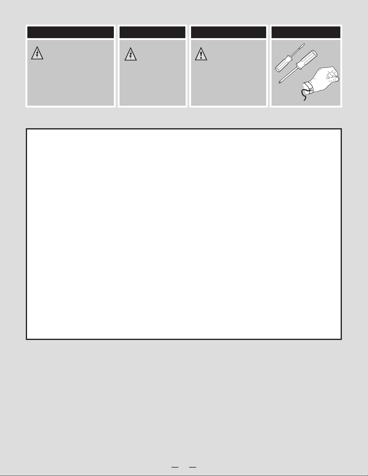
Warning
Warning Caution
Tools Required
Read all caution and safety
statements in this document
before performing any of the
instructions. Also see the Intel®
Server Board and Server Chassis
Safety Information document at:
http://www.intel.com/support/
Installation and service
of this product to be
performed only by
qualified service personnel
to avoid risk of injury from
electrical shock or energy
hazard.
Observe normal ESD
[Electrostatic Discharge]
procedures during system
integration to avoid possible
damage to server board and/or
other components.
motherboards/server/sb/cs-010770
.htm for complete safety information.
Intel® is a registered trademark of Intel Corporation or its subsidiaries in the United States and other countries. *Other names and brands may be claimed as
the property of others. Copyright © 2013, Intel Corporation. All rights reserved.
Flat Blade
screwdriver
Phillips*
screwdriver
Anti-static
wrist strap
Thermal Operation and Configuration Requirements
To keep the system operating within supported maximum thermal limits, the system must meet the following operating and configuration
guidelines:
• Ambient in-let temperature cannot exceed 35º C and should not remain at this maximum level for long periods of time. Doing so
may affect long term reliability of the system.
• DIMM Population on CPU: Install DIMMs in order; Channels A, and B. Start with 1st DIMM slot (blue) on each
channel.
• All hard drive bays must be populated. Hard drive carriers either can be populated with a hard drive or supplied drive blank.
• In single power supply configurations, the second power supply bay must have the supplied filler blank installed at all times.
• The system top-cover must be installed at all times.
ii
Page 5
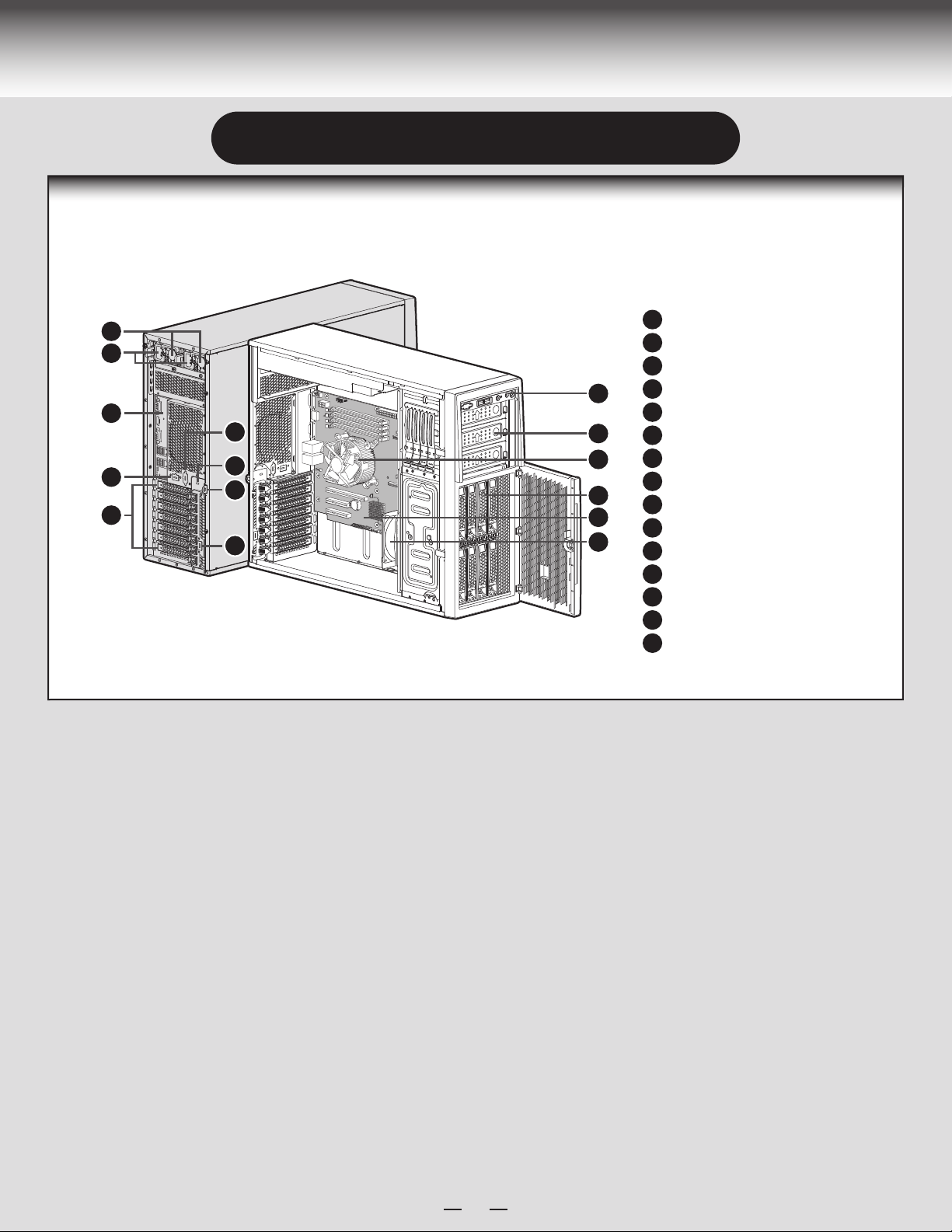
System Overview
Intel® Server System P4308RPLSHDR
System Features and Components
A
B
C
F
D
E
G
H
I
M
460W Hot Swap Power Supply (Two)
A
AC Input Power Connector (Two)
B
I/O Ports
C
RMM4 Knockout
J
K
L
N
O
D
PCI Add-in Board Slot Covers
E
Alternate Serial Port Knockout
F
A Kensington* Cable Lock Mounting Hole
G
Padlock Loop
H
Alternate RMM4 Knockout
I
Front Control Panel
J
5.25" Peripheral Bays
K
Active Heatsink
L
8 x 3.5" Hot-swap HDD Cage
M
Server Board
N
System Fan
O
1
Page 6
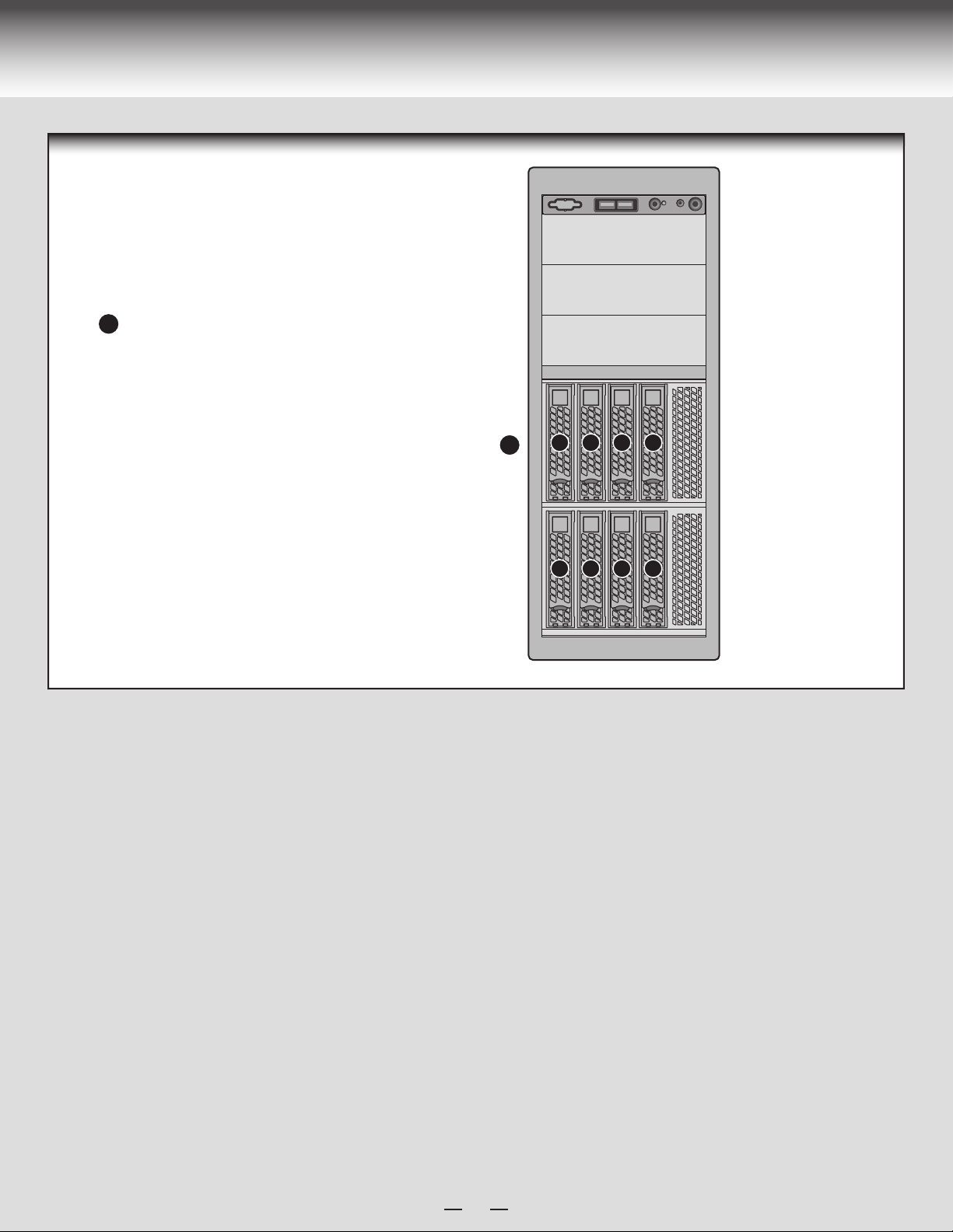
System Overview
Hot Swap Hard Drive
Bay Options and
HDD Numbering
8 x 3.5" Hot-Swap Drive Cage
A
A
4567
0123
2
Page 7

General Installation Process
The installation instructions in this section are for general components of Intel® Server System
P4000RP family.
Minimum Hardware Requirements
To avoid integration difficulties and possible damage to your system,
make sure you have components from each category below.
■ Processor
■ Heat Sink
■ Memory
■ Hard Disk Drives
■ Power
2
Remove the Side Cover
A
Remove the screws.
Slide the side cover back and lift the cover outward to remove it.
B
NOTE:
A non-skid surface or a stop behind the chassis may be needed to prevent the
chassis from sliding on your work surface.
1
Preparing the System
Observe normal ESD (Electrostatic Discharge) procedures.
Place your Intel® Server System on a flat anti-static
surface to perform the following integration procedures.
Observe ESD procedures before reaching inside to make
server board connections or install components.
A
B
3
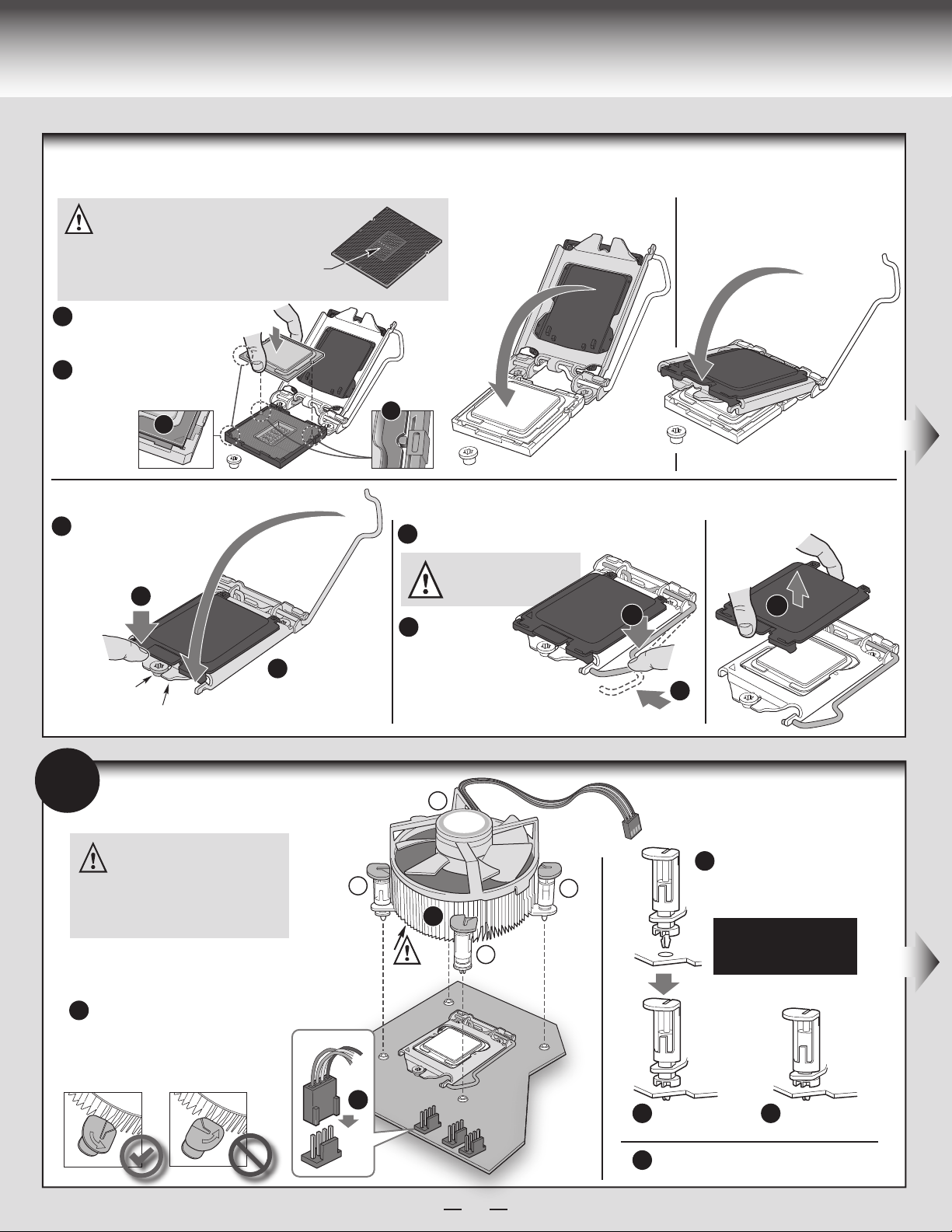
Install the Processor
Cautions:
When removing the protective
cover, DO NOT TOUCH the
gold socket pins.
A
To avoid damage, DO NOT
DROP the cover onto the
socket pins or components.
B
When unpacking a processor,
hold by the edges only to avoid
touching the gold contact pins.
C
A. Open the Socket Lever
Push the lever
A
handle
down
and away
from the socket
to release it.
B
Rotate the lever
open all the way.
A
A
B. Open the Load Plate
Open the load
plate as shown.
C. Unpack the Processor
Carefully remove
protective cover
as shown.
Save the
protective
cover.
3
Page 8
General Installation Process
Install the Processor ... continued
D.
Install the Processor
CAUTION: The underside of the processor has components
that may damage the socket wires if installed improperly.
Processor must align correctly with the socket opening
before installation.
DO NOT DROP processor into socket!
Orient the processor with the socket
A
so that the processor cutouts match
the two socket pins.
Note location of gold key at
B
corner of processor.
Components
Carefully lower the load plate
over the processor.
E. Close the Load Plate
Carefully lower the load plate
over the processor.
B
F. Engage the Load Plate
Make sure the front edge
A
of the load plate slides
under the shoulder screw
as the lever is lowered.
A
Shoulder
Screw
Load Plate
Front Edge
4
Install Active Heat Sink
CAUTION: The heat sink has
thermal interface material (TIM) on
the underside of it. Use caution so
that you do not damage the thermal
interface material. Use gloves to
avoid sharp edges.
Use the following procedure to install an
active heat sink to your server board:
Close the load
B
plate locking
lever.
A
G. Latch the Locking Lever
Push down on the locking lever.
A
CAUTION: DO NOT damage the
server board with the tip of the
locking lever.
Slide the tip of
B
the lever under
the notch in the
load plate. Make sure the
lever is securely latched.
3
2
A
4
TIM
Note: Heatsink
styles may vary
1
H.
Remove the Cover
Carefully lift the cover straight up
as shown.
A
A
A
Save the
protective
cover.
B
Align heat sink with holes
B
in board and lower assembly
to board. Snaps go through
holes in server board.
Repeat B-D for each
fastener in the numerical
order shown at left.
Make sure the screwdriver slot at
A
the top of each fastener is rotated
perpendicular to the blades of
the heat sink as shown.
E
4
Press downward
C
on top of cap.
Plug the fan cable into the CPU fan header.
E
Fastener snaps
D
into final position.
Page 9

General Installation Process
5
Install DIMM Memory Modules
DDR3L DIMM Memory Identification:
CAUTION: Observe normal ESD (ElectroStatic Discharge) procedures
to avoid possible damage to system components.
This server board supports up to 4 DDR3L 1333/1600 ECC UDIMM.
Non-ECC memory is NOT supported by this server board.
DIMM
notch and
socket
bump must
align as
shown.
DDR3
Other
Memory
Install DIMM Memory Modules... Continued
To Install DIMMs:
CAUTION: Avoid touching contacts when handling or installing DIMMs.
Open both DIMM socket levers.
A
Note location of alignment notch.
B
Insert DIMM making sure the connector edge of the DIMM aligns correctly with the slot.
C
Push down firmly on the DIMM until it snaps into place and both levers close.
D
IMPORTANT! Visually check that each latch is fully closed
E
and correctly engaged with each DIMM edge slot.
E
D
C
B
A
For the best performance, a minimum of two DIMMs is recommended, populated
in the blue slot of each memory channel.
Note: For additional memory configurations, see the Service Guide on the
®
Server Deployment & Management DVD that accompanied
Intel
®
your Intel
http://www.intel.com/p/en_US/support/ (post-production)
Memory sizing and configuration is supported only for qualified DIMMs approved by
Intel
http://serverconfigurator.intel.com/sct_app.aspx (post-production)
Server System, or go to:
®
. For a list of supported memory, go to:
Intel® Server Board S1200V3RPL
DIMM_A2
DIMM_A1
CPU Socket
DIMM_B2
DIMM_B1
5
Page 10

General Installation Process
6
7
Install Tool-less CD-ROM or DVD-ROM Drive
Finger Holes
A
Press the release latch and use
A
the finger holes to Pull out the
EMI shield.
Get the slides from the
B
chassis side.
Attach slides to the DVD or CD-ROM drive
C
by pressing the slides firmly into the side
dimples on the DVD or CD-ROM drive.
Install Hard Drive
3.5" Hot-Swap Hard Drive Carrier
B
D
C
Insert the drive/slide assembly
D
into the device bay until the
slides lock into place.
B
Open the Hot-swap door and
A
remove the drive carrier by
pressing the green button and
opening the lever.
Slide the carrier out.
B
BREAK OFF TAB
BEFORE MOUTING
2.5´´ HARD DRIVE
TOP
3.5´´ HDD
A
Remove the four screws securing the
C
HDD interface bracket and remove the
HDD interface bracket.
C
F
E
D
Install the hard disk drive using the same four
D
screws as shown. Make sure the connector
end of the drive matches the backplane
connector.
CAUTION: If you don’t install all drives,
empty drive bays must be occupied by
carriers with plastic drive blank
provided to maintain proper system cooling.
With the lever open, insert the
E
hard disk drive assembly into the
cage opening and push until the
locking lever engaged.
Push in the lever to lock it into
F
place, then close the door.
6
Page 11

General Installation Process
RMM4
Connector
Server
Board
Chassis
Back
Opening
Filler
8
Install PCI-e Card Assembly
Remove the PCI slot shield by pushing the
A
shield out from inside the chassis.
A
9
Install Intel® Remote Management Module 4 NIC (optional)
Server
Board
From inside of chassis, press open the back
B
panel PCI add-in board retention device.
B
Server
Board
While holding the PCI add-in board by its top edge or
C
upper corners, firmly press the add-in board into the
expansion slot.
D
Close the PCI add-in
board retention device.
D
Server
Board
C
Top View
D
A
Attach the metal fastening bracket to Intel® Dedicated Server Management NIC module and
A
secure the bracket with two screws.
Remove the alternate RMM4 knock out by pressing the knock out from inside the chassis.
B
CAUTION
Connect the cable to the cable connector on the Intel® Dedicated Server Management NIC module.
C
Mount the NIC module to the rear panel of the chassis and secure the bracket with two screws.
D
Connect the cable to the RMM4 NIC connector to the RMM4 NIC connector on your server board.
E
CAUTION
: Carefully remove the knock out with screwdriver, directly removing it with finger has potential risk.
: Care should be used when attaching or removing this cable. Mishandling the cable could cause damage.
7
B
Server
Board
Latch
C
E
Page 12

General Installation Process
Chassis
Back
Opening
Filler
10
Install RMM4 EMI Cover (optional)
Install the RMM4 EMI cover with
A
thumb screws.
B
11
A
B
C
D
Install Alternate Serial Port (optional)
A
Serial B
D
Connector
B
Server
Board
C
Remove the alternate serial port knockout by
pressing the knockout from inside the chassis.
CAUTION
directly removing it with finger has potential risk.
Mount the serial serial port on the rear panel of the chassis.
secure the port with two screws.
Connect the cable to the Serial B Connector on your server board.
CAUTION
this cable. Mishandling the cable could cause damage.
: Carefully remove the knock out with screwdriver,
: Care should be used when attaching or removing
12
Install Intel® RAID Smart Battery (optional)
Align the tabs on the plastic battery holder with the mounting
A
holes in the chassis and slide the plastic battery holder toward
the front of the chassis until the tabs engage with the
mounting holes.
Server
A
Board
8
Page 13

General Installation Process
13
Install Second Power Supply Module (optional)
Finger
Hole
A
Use the 'finger hole' to remove the
A
filler panel.
NOTE: Applies only to the chassis with hot-swap power supply configuration.
B
B
Insert the power supply module into the power
supply cage and push all the way until it clicks
into place.
Latch
Handle
To remove a power supply module, push the
green latch in the direction shown and pull
out of the system by the handle.
14
A
B
Install Side Cover
Slide the chassis cover on the chassis.
Secure the chassis cover with the screws .
CAUTION: This chassis must be operated with the
SIDE COVERS installed to ensure proper cooling.
B
A
15
Finishing Up
See your Intel
1.
Board Quick Start
User's Guide to connect
your keyboard, mouse,
video, and other I/O cables.
Connect the AC
2.
power cable last.
®
Server
CAUTION:
power supply
requires a
16-gauge
power cord.
AC
Power
A
B
9
Page 14

General Installation Process
16
Install Software
• BIOS, Drivers, and Operating System Install
A. Confirm BIOS Version:
versions at:
If new versions are available, update the BIOS on your server. See the User Guide on the Intel
B. Configure your RAID Controller:
C. Install your Operating System:
D. Install Operating System Drivers:
Windows* operating system, the Express Installer will autorun and allow you to select the appropriate drivers to install. On other operating systems, browse the
DVD folders to locate and install the driver files.
http://www.intel.com/support
Look on the Server/System Management screen in the BIOS Setup Utility to determine the installed BIOS version.
®
Server Deployment and Management DVD for update instructions.
Use the instructions provided with the RAID controller.
Use the instructions provided with the RAID controller and with the operating system.
With the operating system running, insert the Intel® Server Deployment and Management DVD. If using a Microsoft
Compare this to the
10
Page 15

Reference
HDD Cage Cable Connection
NOTE: Refer to the documents which come with your server board and/or RAID controller card for instructions on connecting backplane cables to your server board or
RAID controller card.
8 x 3.5" HDD Cage
C
Connect the I2C cable to I2C connector on backplane.
A
Connect Mini SAS data cables.
B
Connect two power cables.
C
B
A
11
Page 16

Reference
Front Panel Controls and Indicators
H
A
USB Connectors
ID Button with ID LED Integrated
B
NMI Button
C
K
A B
D
System Reset Button HDD Activity LED
E
System Status LED
F
Cable Routing Diagram
Power Supply
CPU Power
SYS_FAN_4
PS AUX
Main Power
B
H
D
C
E
A
C
D E
F
G
G
System Power Button with Power LEDNIC LED
H
F
Server Board
Integrated
®
Intel
RAID Module
SYS_FAN_1
SAS SPGIO
HSBP_I2C
SATA
Front Panel
A. CPU Power Cable
B. Server Board Main Power Cable
C. Backplane Power Cable
D. ODD Power Cable
E. Front Panel Cable and USB Cable
F. ODD Data Cable (Connect to White SATA 6G Connectors on Server Board)
G. SATA/SAS Cable and SGPIO Cable (Connect to SATA/SAS 0-3 on Server Board)
H. PS AUX Cable
I. HSBP_I
J. PCI Zone System FAN
K. REAR FAN
2
C Cable
USB
®
Intel
Server System P4304FP2SFCN
Description
J
12
I
G
Page 17

Page 18

G85600-002
 Loading...