

Page 1

Intel® Server Chassis P4000M Family
Service Guide
A Guide for Technically Qualified Assemblers of Intel® identified
Subassemblies/Products
Order Number: G30559-005
Page 2

Disclaimer
Disclaimer
INFORMATION IN THIS DOCUMENT IS PROVIDED IN CONNECTION WITH INTEL® PRODUCTS. NO
LICENSE, EXPRESS OR IMPLIED, BY ESTOPPEL OR OTHERWISE, TO ANY INTELLECTUAL PROPERTY
RIGHTS IS GRANTED BY THIS DOCUMENT. EXCEPT AS PROVIDED IN INTEL
®
'S TERMS AND CONDITIONS
OF SALE FOR SUCH PRODUCTS, INTEL® ASSUMES NO LIABILITY WHATSOEVER AND INTEL®
DISCLAIMS ANY EXPRESS OR IMPLIED WARRANTY, RELATING TO S ALE AND/OR USE OF INTEL
PRODUCTS INCLUDING LIABILITY OR WARRANTIES RELATING TO FITNESS FOR A PARTICULAR
PURPOSE, MERCHANTABILITY, OR INFRINGEMENT OF ANY PATENT, COPYRIGHT OR OTHER
INTELLECTUAL PROPERTY RIGHT.
A "Mission Critical Application" is any application in which failure of the Intel
indirectly, in personal injury or death. SHOULD YOU PURCHASE OR USE INTEL
®
Product could result, directly or
®
'S PRODUCTS FOR ANY SUCH
MISSION CRITICAL APPLICATION, YOU SHALL INDEMNIFY AND HOLD INTEL® AND ITS SUBSIDIARIES,
SUBCONTRACTORS AND AFFILIATES, AND THE DIRECTORS, OFFICERS, AND EMPLOYEES OF EACH,
HARMLESS AGAINST ALL CLAIMS COSTS, DAMAGES, AND EXPENSES AND REASONABLE ATTORNEYS'
FEES ARISING OUT OF, DIRECTLY OR INDIRECTLY, ANY CLAIM OF PRODUCT LIABILITY, PERSONAL
INJURY, OR DEATH ARISING IN ANY WAY OUT OF SUCH MISSION CRITICAL APPLICATION, WHETHER
OR NOT INTEL
®
OR ITS SUBCONTRACTOR WAS NEGLIGENT IN THE DESIGN, MANUFACTURE, OR
WARNING OF THE INTEL® PRODUCT OR ANY OF ITS PARTS.
®
Intel
may make changes to specifications and product descriptions at any time, without notice. Designers must not rely
on the absence or character istics of any features or instructions marked "reserved" or "undefined". Intel® reserves these
for future definition and shall have no responsibility whatsoever for conflicts or incompatibilities arising from future
changes to them. The information here is subject to change without notice. Do not finalize a design with this information.
The products described in this document may contain design defects or errors known as errata which may cause the
product to deviate from published specifications . Current characterized errata are available on request.
Contact your local Intel
®
sales office or your distributor to obtain the latest specifications and before placing your product
order.
Copies of documents which have an order number and are referenced in this document, or other Intel
obtained by calling 1-800-548-4725, or go to: http://www.intel.com/design/literature
.
®
literature, may be
®
ii Intel
®
Server Chassis P4000M Service Guide
Page 3

Safety Information
重要安全指导
Safety Information
Important Safety Instructions
Read all caution and safety statements in this document before performing any of the instructions.
See also Intel
Deployment Toolkit 3.0 CD and/or at
http://www.intel.com/support/motherboards/server/sb/cs-010770.htm
Wichtige Sicherheitshinweise
Lesen Sie zunächst sämtliche Warnund Sicherheitshinweise in diesem Dokument, bevor Sie eine
der Anweisungen ausführen. Beachten Sie hierzu auch die Sicherheitshinweise zu Intel
Serverplatinen und Servergehäusen auf der Intel
http://www.intel.com/support/motherboards/server/sb/cs-010770.htm
Consignes de sécurité
Lisez attention toutes les consignes de sécurité et les mises en garde indiquées dans ce document
avant de suivre toute instruction. Consultez Intel
Information sur le Intel
http://www.intel.com/support/motherboards/server/sb/cs-010770.htm
®
Server Boards and Server Chassis Safety Information on the Intel® Server
.
®
Server Deployment Toolkit 3.0 CD oder unter
.
®
®
Server Deployment Toolkit 3.0 CD ou bien rendez-vous sur le site
Server Boards and Server Chassis Safety
..
®
-
Instrucciones de seguridad importantes
Lea todas las declaraciones de seguridad y precaución de este documento antes de realizar
cualquiera de las instrucciones. Vea Intel
®
el Intel
Server Deployment Toolkit 3.0 CD y/o en
http://www.intel.com/support/motherboards/server/sb/cs-010770.htm
在执行任何指令之前,请阅读本文档中的所有注意事项及安全声明。和/或
http://www.intel.com/support/motherboards/server/sb/cs-010770.htm
and Server Chassis Safety Information(《Intel 服务器主板与服务器机箱安全信息》)。
®
Server Boards and Server Chassis Safety Information en
.
上的 Intel® Server Boards
®
Intel
Server Chassis P4000M Service Guide iii
Page 4

Warnings
Warnings
Heed safety instructions: Before working with your server product, whether
you are using this guide or any other resource as a reference, pay close
attention to the safety instructions. You must adhere to the assembly
instructions in this guide to ensure and maintain compliance with existing
product certifications and approvals. Use only the described, regulated
components specified in this guide. Use of other products/components will
void the UL listing and other regulatory approvals of the product and will
most likely result in noncompliance with product regulations in the region(s)
in which the product is sold.
System power on/off: The power button DOES NOT turn off the system AC
power. To remove power from the system, you must unplug the AC power
cord from the wall outlet. Make sure the AC power cord is unplugged before
you open the chassis, add, or remove any components.
Hazardous conditions, devices and cables: Haza rdous electrical conditions
may be present on power, telephone, and communication cables. Turn off the
server and disconnect the power cord, telecommunications systems, networks,
and modems attached to the server before opening it. Otherwise, personal
injury or equipment damage can result.
Electrostatic discharge (ESD) and ESD protection: ESD can damage disk
drives, boards, and other parts. We recommend that you perform all
procedures in this chapter only at an ESD workstation. If one is not available,
provide some ESD protection by wearing an antistatic wrist strap attached to
chassis groundany unpainted metal surfaceon your server when
handling parts.
ESD and handling boards: Always handle boards carefully. They can be
extremely sensitive to ESD. Hold boards only by their edges. After remov in g
a board from its protective wrapper or from the server, place the board
component side up on a grounded, static free surface. Use a conductive foam
pad if available but not the board wrapper. Do not slide board over any
surface.
Installing or removing jumpers: A jumper is a small plastic encased
conductor that slips over two jumper pins. Some jumpers have a small tab on
top that you can grip with your fingertips or with a pair of fine needle nosed
pliers. If your jumpers do not have such a tab, take care when using needle
nosed pliers to remove or install a jumper; grip the narrow sides of the
jumper with the pliers, never the wide sides. Gripping the wide sides can
damage the contacts inside the jumper, causing intermittent problems with
the function controlled by that jumper. Take care to grip with, but not
squeeze, the pliers or other tool you use to remove a jumper, or you may
bend or break the pins on the board.
iv Intel
®
Server Chassis P4000M Service Guide
Page 5
Preface
For in-depth technical information
Intel® Server Chassis P4000M Family Technical Product Specification
If you just received this product and
Intel® Server Chassis P4000M Family Quick Installation User’s Guide
Accessories or other Intel® server
Spares and Configuration Guide
Intel® Server Configurator tool
To make sure your system falls within
Power Budget Tool
For software to manage your Intel®
Intel® Server Management Software
For firmware and drivers.
Firmware and Drivers
Preface
About this Manual
Thank you for purchasing and using the Intel® Server Chassis P4000M family products.
This manual is written for system technicians who are responsible for troubleshooting, upgrading,
and repairing this server chassis. This document provides a brief overview of the features of the
board/chassis, a list of accessories or other components you may need, troubleshooting information,
and instructions on how to add and replace components on the Intel
family. For the latest version of this manual, refer to http://www.intel.com/p/en_US/support
Manual Organization
Chapter 1 provides a brief overview of the Intel® Server Chassis P4000M family. In this chapter,
you will find a list of the server chassis features, photos of the product, and product diagrams to
help you identify components and their locations.
Chapter 2 provides instructions on adding and replacing components. Use this chapter for step-bystep instructions and diagrams for installing or replacing components such as the fan, power supply,
front panel board, and battery, among other components.
Chapter 3 provides technical reference information on cable routing, power supply specifications,
and system environment requirements.
At the back of this document, you will find appendices on safety, getting help, and warranty
information.
®
Server Chassis P4000M
.
Additional Information and Software
If you need more information about this product or information about the accessories that you can
use with this server chassis, use the following resources. These files are available at:
http://www.intel.com/p/en_US/support
Unless otherwise indicated in the following table, once on this web page, type the document or
software name in the search field at the left side of the screen and select the option to search “This
Product”.
For this information or software Use this Document or Software
about this product.
need to install it.
products.
To quickly and efficiently select
compatible components to design a
complete system.
the allowed power budget.
server.
See the section on the web page titled, “Document and Guides”.
.
®
Intel
Server Chassis P4000M Service Guide v
Page 6

Table of Contents
Table of Contents
Safety Information ...............................................................................................iii
Preface ..................................................................................................................v
1 Server Chassis Features ................................................................................1
Chassis Features ................................................................................................................ 2
Component Identification ................................................................................................... 3
Hot Swap Hard Drive Bay Options and HDD Numbering .................................................. 5
Front Panel .......................................................................................................................... 6
Back Panel ........................................................................................................................... 8
Hotswap SAS/SATA Backplane .......................................................................................... 9
4x3.5'' Hard Drive Backplane .............................................................................................. 9
8x3.5'' Hard Drive Backplane ............................................................................................ 10
8x2.5'' Hard Drive Backplane ............................................................................................ 11
2 Hardware Installations and Upgrades ........................................................ 13
Before You Begin .............................................................................................................. 13
Tools and Supplies Needed ..................................................................................... 13
System Reference .................................................................................................... 13
Removing and Installing the Chassis Cover ................................................................... 13
Removing the Chassis Cover .................................................................................. 13
Installing the Chassis Cover .................................................................................... 14
Removing and Installing the Front Bezel (Pedestal Only) .............................................. 15
Removing the Front Bezel (Pedestal Only) ............................................................. 15
Installing the Front Bezel (Pedestal Only) .............................................................. 16
Converting the Pedestal Chassis to Rack Mount Chassis .................................... 16
Installing and/or Removing Airduct ................................................................................. 20
Installing the Airduct ................................................................................................ 20
Removing the Airduct .............................................................................................. 21
Replacing the Fixed Fan ................................................................................................... 21
Removing the Fixed Fan .......................................................................................... 21
Installing the Fixed Fan ............................................................................................ 22
Removing and Installing the Hotswap Fan ...................................................................... 23
Removing the Hotswap Fan ..................................................................................... 23
Installing the Hotswap Fan ...................................................................................... 24
Removing and Installing the Fixed HDD EMI Shield ....................................................... 24
Removing the Fixed HDD EMI Shield ...................................................................... 24
Installing the Fixed HDD EMI Shield ........................................................................ 25
Removing and Installing Fixed Hard Drive(s) .................................................................. 26
Removing Fixed Hard Drive(s) ................................................................................. 26
Installing Fixed Hard Drive(s) .................................................................................. 27
Removing and Installing 4x3.5” Hotswap Hard Drive Cage Assembly .......................... 29
Removing 4x3.5” Hotswap Hard Drive Cage with Backplane ................................ 29
Installing 4x3.5'' Hotswap Hard Drive Cage with Backplane ................................. 30
Removing and Installing 4x3.5'' Hotswap Backplane ..................................................... 32
Removing 4x3.5'' Hotswap Backplane .................................................................... 32
Installing 4x3.5” Hotswap Backplane ...................................................................... 33
Removing and Installing 8x3.5'' Hotswap Hard Drive Cage Assembly .......................... 34
vi Intel
®
Server Chassis P4000M Service Guide
Page 7

Table of Contents
Removing 8x3.5'' Hotswap Hard Drive Cage Assembly ......................................... 34
Installing 8x3.5'' Hotswap Hard Drive Cage Assembly .......................................... 35
Removing and Installing 8x3.5'' Hotswap Backplane ..................................................... 36
Removing 8x3.5'' Hotswap Backplane .................................................................... 36
Installing 8x3.5'' Hotswap Backplane ...................................................................... 37
Removing and Installing 8x2.5'' Hotswap Hard Drive Cage Assembly .......................... 38
Removing 8x2.5'' Hotswap Hard Drive Cage Assembly ......................................... 38
Installing 8x2.5'' Hotswap Hard Drive Cage Assembly .......................................... 39
Removing and Installing the Hotswap HDD EMI Shield .................................................. 40
Removing the Hotswap HDD EMI Shield ................................................................. 40
Installing the Hotswap HDD EMI Shield .................................................................. 41
Removing and Installing Second 8x2.5'' Hotswap Hard Disk Drive Cage Assembly .... 42
Removing Second 8x2.5'' Hotswap Hard Disk Drive Cage Assembly ................... 42
Installing Second 8x2.5'' Hotswap Hard Disk Drive Cage Assembly .................... 43
Removing and Installing 8x2.5'' Hotswap Backplane ..................................................... 44
Removing 8x2.5'' Hotswap Backplane .................................................................... 44
Installing 8x2.5'' Hotswap Backplane ...................................................................... 45
Installing Hotswap Hard Drive .......................................................................................... 46
Installing 3.5" Hotswap Hard Disk Drive ................................................................. 46
Installing 2.5" Hotswap Hard Disk Drive in 3.5'' HDD Carrier ................................ 48
Installing 2.5" Hotswap Hard Disk Drive in 2.5'' HDD Carrier ................................ 51
Installing and Removing a DVD or CD-ROM Drive .......................................................... 53
Installing a DVD or CD-ROM Drive .......................................................................... 53
Removing a DVD or CD-ROM Drive ......................................................................... 54
Installing PCI Add-in Board(s) .......................................................................................... 55
Installing a Double Width Card Extension Bracket ......................................................... 58
Removing and Installing the Fixed Power Supply .......................................................... 59
Removing the Fixed Power Supply ......................................................................... 59
Installing the Fixed Power Supply ........................................................................... 60
Installing an Additional Hotswap Power Supply Module ................................................ 61
Replacing a Hot Swap Power Supply Module ................................................................. 62
Replacing the Power Distribution Board for 460W/750W PSUs ..................................... 63
Replacing the Power Distribution Board for 1200-W PSUs ............................................ 68
Removing and Installing the Top Cosmetic Cover ......................................................... 70
Removing the Top Cosmetic Cover ........................................................................ 70
Installing the Top Cosmetic Cover .......................................................................... 70
Removing and Installing the Chassis Feet ...................................................................... 71
Removing the Chassis Feet ..................................................................................... 71
Installing the Chassis Feet (Pedestal Configuration Only) .................................... 71
Removing and Installing the Front Panel Tray ................................................................ 72
Removing the Front Control Panel Tray ................................................................. 72
Installing the Front Panel Tray ................................................................................ 74
Replacing the Front Panel Board ..................................................................................... 76
Installing Alternate Serial Port ......................................................................................... 77
Installing and/or Removing a Expander card .................................................................. 78
Installing the Expander card .................................................................................... 78
Removing the Expander card .................................................................................. 78
Installing and/or Removing a Server/Workstation Board ............................................... 79
Connecting and Disconnecting Cables to or from Server Workstation Board ............. 80
Connecting Cables to Server/Workstation Board .................................................. 80
Removing Cables from Server/Workstation Board ................................................ 80
®
Intel
Server Chassis P4000M Service Guide vii
Page 8

Table of Contents
Rack-mounted Systems .................................................................................................... 80
®
Intel
Remote Management Module 4 .............................................................................. 81
Mechanical Locks ............................................................................................................. 82
3 Technical Reference .................................................................................... 83
Power Supply Specification ............................................................................................. 83
460-W Hotswap Power Supply Input Voltage ......................................................... 83
460-W Hotswap Power Supply Output Voltages .................................................... 83
550-W Single Power Supply Input Voltage ............................................................. 83
550-W Single Power Supply Output Voltages ......................................................... 83
750-W Hotswap Power Supply Input Voltage ......................................................... 84
750-W Hotswap Power Supply Output Voltages .................................................... 84
1200-W Hotswap Power Supply Input Voltage ....................................................... 84
1200-W Hotswap Power Supply Output Voltages................................................... 84
System Environmental Requirements ............................................................................. 85
Current Usage ................................................................................................................... 85
Calculation Power Usage ......................................................................................... 85
Appendix A: Regulatory and Compliance Information .................................. 87
Appendix B: Safety Information ....................................................................... 88
Appendix C: Installation/Assembly Safety Instructions ................................ 89
Appendix D: Getting Help ................................................................................. 90
Warranty Information ............................................................................................... 90
Appendix E: Intel® Server Issue Report Form ................................................ 91
Appendix F: Warranty ....................................................................................... 96
®
Limited Warranty for Intel
Extent of Limited Warranty ............................................................................................... 96
Warranty Limitations and Exclusions .............................................................................. 96
Limitations of Liability .............................................................................................. 97
How to Obtain Warranty Service ...................................................................................... 97
Telephone Support ................................................................................................... 97
Returning a Defective Product ................................................................................ 97
Chassis Subassembly Products ......................................... 96
viii Intel
®
Server Chassis P4000M Service Guide
Page 9

List of Figures
List of Figures
Figure 1. Chassis Front View for Fixed Hard Drive ................................................................. 1
Figure 2. Chassis Front View for H otswap Hard Dri ve ........................................................... 1
Figure 3. Internal Chassis View of Intel
Supply, Fixed Hard Drives, Fixed System Fans ............................................................... 3
Figure 4. Internal Chassis View of Intel
Supply, Hotswap Hard Drives and Hotswap System Fans .............................................. 4
Figure 5. 4x3.5'' Hotswap Drive Cage ...................................................................................... 5
Figure 6. 8x3.5'' Hotswap Drive Cage ...................................................................................... 5
Figure 7. 8x2.5'' Hotswap Drive Cage ...................................................................................... 6
Figure 8. Two 8x2.5'' Hotswap Drive Cages ............................................................................ 6
Figure 9. Front Panel Controls and Indicators ........................................................................ 7
Figure 10. Back Panel Layout (with Fixed Power Supply) ...................................................... 8
Figure 11. Back Panel Layout (with Hotswap Power Supply) ................................................ 8
Figure 13. 4x3.5'' HSBP Board Layout (Front View) ............................................................. 10
Figure 14. 8x3.5'' HSBP Board (Rear View) ........................................................................... 10
Figure 15. 8x3.5'' HSBP Board (Front View) .......................................................................... 11
Figure 16. 8x2.5'' HSBP Board (Front View) .......................................................................... 11
Figure 17. 8x3.5'' HSBP Board (Front View) .......................................................................... 12
Figure 18. Removing the Chassis Cover ............................................................................... 14
Figure 19. Installing the Chassis Cover ................................................................................. 14
Figure 20. Removing the Front Bezel .................................................................................... 15
Figure 21. Installing the Front Bezel ...................................................................................... 16
Figure 23. Removing the Fillers ............................................................................................. 17
Figure 24. Removing the Top Board ...................................................................................... 17
Figure 25. Installing the Front Panel ...................................................................................... 17
Figure 26. Installing the Drive (optional) ............................................................................... 18
Figure 28. Installing the Rack Mount handles ....................................................................... 19
Figure 29. Installing the Rack Bezel ...................................................................................... 19
Figure 31. Installing the Airduct ............................................................................................. 20
Figure 32. Disconnecting the fan power cable from the server board ................................ 21
Figure 33. Removing fixed system fan from chassis ........................................................... 22
Figure 34. Inserting the fan cable in the corresponding fan bracket................................... 22
Figure 35. Installing the Fixed Fan ......................................................................................... 23
Figure 36. Removing Hotswap Fan ........................................................................................ 23
Figure 37. Installing Hotswap Fan ......................................................................................... 24
Figure 38. Removing the Fixed HDD EMI Shield ................................................................... 25
Figure 39. Installing the Fixed HDD EMI Shield .................................................................... 25
Figure 40. Removing Fixed Hard Drives ................................................................................ 26
Figure 41. Removing the 3.5” HDD from Fixed HDD tray ..................................................... 26
Figure 42. Removing the 2.5” HDD from Fixed HDD tray ..................................................... 27
Figure 43. Reinstalling the HDD Carrier Tray ........................................................................ 27
Figure 44. Removing Fixed Hard Drive .................................................................................. 28
Figure 45. Securing the 3.5” HDD on Fixed HDD Carrier Tray ............................................. 28
Figure 46. Securing the 2.5” HDD on Fixed HDD Carrier Tray ............................................. 29
Figure 47. Inserting the HDD Carrier Tray ............................................................................. 29
Figure 48. Removing the 4x3.5” HDD Cage ........................................................................... 30
Figure 49. Removing the EMI shield ...................................................................................... 30
®
Server Chassis P4000M with Fixed Power
®
Server Chassis P000M with Hotswap Power
®
Intel
Server Chassis P4000M Service Guide ix
Page 10

List of Figures
Figure 50. Installing the EMI shield ........................................................................................ 31
Figure 51. Installing the 4x3.5'' Hotswap Hard Drive Cage .................................................. 31
Figure 52. 4x3.5'' Hot Swap Backplane Cable Connections ................................................. 32
Figure 53. Removing 4x3.5'' Hotswap Backplane ................................................................. 33
Figure 54. Installing 4x3.5” Hotswap Backplane .................................................................. 33
Figure 55. Removing the 8x3.5'' Hotswap HDD Cage Assembly ......................................... 34
Figure 56. Installing the 8x3.5'' Hotswap Hard Drive Cage Assembly ................................. 35
Figure 57. 8x3.5'' Hot Swap Backplane Cable Connections ................................................. 36
Figure 58. Removing 8x3.5” Hotswap Backplane ................................................................. 37
Figure 59. Installing 8x3.5'' Hotswap Backplane ................................................................... 37
Figure 60. Removing the 8x2.5'' HDD Cage Assembly ......................................................... 38
Figure 61. Installing the 8x2.5'' Hotswap Hard Drive Cage Assembly ................................. 39
Figure 62. 8x2.5” Hot Swap Backplane Cable Connections ................................................. 40
Figure 63. Removing the Hotswap HDD EMI Shield ............................................................. 41
Figure 64. Installing the Hotswap HDD EMI Shield ............................................................... 41
Figure 65. Removing the bottom 8x2.5'' Hotswap HDD Cage Assembly ............................. 42
Figure 66. Installing the Second 8x2.5'' Hotswap Hard Drive Cage Assembly ................... 43
Figure 67. Two 8x2.5” Hot Swap Backplane Cable Connections ......................................... 44
Figure 68. Removing 8x2.5'' Hotswap Backplane ................................................................. 45
Figure 69. Installing 8x2.5'' Hotswap Backplane ................................................................... 45
Figure 70. Sliding the 3.5'' HDD carrier out ........................................................................... 46
Figure 71. Removing the 3.5" HDD interface bracket from Carrier ...................................... 47
Figure 72. Installing the 3.5" HDD into the Carrier ................................................................ 47
Figure 73. Sliding the 3.5" HDD Carrier into the C hassis ..................................................... 48
Figure 74. Removing the 3.5" HDD interface bracket from Carrier ...................................... 48
Figure 75. Breaking off the tab on the bracket ...................................................................... 49
Figure 76. Installing 2.5" HDD interface bracket into Carrier ............................................... 49
Figure 77. Installing the 2.5" HDD into carrier ...................................................................... 50
Figure 78. Sliding the 2.5'' HDD Carrier from the chassis .................................................... 51
Figure 79. Removing the plastic retention device from Carrier ........................................... 51
Figure 80. Installing the 2.5'' HDD in Carrier ......................................................................... 52
Figure 81. Installing the 2.5" HDD into the Chassis .............................................................. 52
Figure 82. Removing EMI Shield ............................................................................................ 53
Figure 83. Installing DVD or CD-ROM Drive .......................................................................... 53
Figure 84. Removing DVD or CD-ROM Drive ......................................................................... 54
Figure 85. Re-inserting Empty EMI Shield ............................................................................. 54
Figure 86. Removing the PCI slot shield ............................................................................... 55
Figure 87. Rotate the PCI card retainer ................................................................................. 55
Figure 88. Open the back panel PCI add-in board retention device .................................... 56
Figure 90. Closing the PCI Card Retention Device ............................................................... 57
Figure 91. Closing the PCI Card Retainer .............................................................................. 57
Figure 92. Installing the Double Width Card Fixture ............................................................. 58
Figure 93. Installing the double width card extension bracket ............................................ 58
Figure 94. Secure the Double Width card with Double Width Card bracket ....................... 59
Figure 96. Top View of a Double Width Card Extender Example ......................................... 59
Figure 97. Removing Fixed Power Supply ............................................................................ 60
Figure 98. Installing Fixed Power Supply .............................................................................. 60
Figure 99. Removing Power Supply Filler Panel ................................................................... 61
Figure 100. Installing Additional Hotswap Power Supply Module ....................................... 61
Figure 101. Removing Hotswap Power Supply Module from Chassis ................................ 62
Figure 102. Installing Hotswap Power Supply Module into Chassis ................................... 62
x Intel
®
Server Chassis P4000M Service Guide
Page 11

List of Figures
Figure 103. Removing Hotswap Power Supply Module from Chassis ................................ 63
Figure 104. Loosening the Bracket with Power Distribution Board from Chassis ............. 63
Figure 105. Removing the Bracket with Power Distribution Board from Chassis .............. 64
Figure 106. Removing the Power Distribution Board from Bracket .................................... 64
Figure 107. Sliding the New Power Distribution Board in Bracket ...................................... 65
Figure 108. Securing the New Power Distribution Board in Bracket ................................... 65
Figure 109. Sliding the Bracket into Power Supply Cage ..................................................... 66
Figure 110. Securing the Bracket into Power Supply Cage ................................................. 66
Figure 111. Installing Hotswap Power Supply Module into Chassis ................................... 67
Figure 112. Removing the PDB for 1200-W PSU ................................................................... 68
Figure 113. Installing the PDB for 1200-W PSU .................................................................... 69
Figure 114. Removing the Top Cosmetic Cover ................................................................... 70
Figure 115. Installing the Top Cosmetic Cover ..................................................................... 70
Figure 116. Removing the Chassis Feet ................................................................................ 71
Figure 117. Installing the Chassis Feet ................................................................................. 72
Figure 118. Disconnecting the Cables from the Server Board............................................. 73
Figure 120. Disconnecting the Cables from Front Panel Board .......................................... 74
Figure 122. Installing the Front Panel Tray in Chassis ......................................................... 75
Figure 123. Connecting the Cables to Server Board the Front Panel Tray in Chassis ...... 75
Figure 124. Removing the Front Panel Board ....................................................................... 76
Figure 125. Removing and Installing the Cap on Front Panel Board .................................. 76
Figure 126. Installing the New Front Panel Board ................................................................ 76
Figure 127. Removing the Alternate Serial Port Knockout .................................................. 77
Figure 128. Installing the Alternate Serial Port Knockout .................................................... 77
Figure 130. Removing the Expander card ............................................................................. 79
Figure 131. RMM4 knockout ................................................................................................... 81
Figure 132. Mechanical Locks ................................................................................................ 82
®
Intel
Server Chassis P4000M Service Guide xi
Page 12

List of Tables
List of Tables
Table 1. Intel® Server Chassis P4000M family Base Features ................................................ 2
Table 2. Front Panel LED Functionality ................................................................................... 7
Table 3. 460-W Power Supply Output Voltages .................................................................... 83
Table 4. 550-W Power Supply Output Voltages .................................................................... 84
Table 5. 750-W Power Supply Output Voltages .................................................................... 84
Table 6. 1200-W Power Supply Output Voltages .................................................................. 84
Table 7. Environmental Requirements .................................................................................. 85
Table 8. Power Usage Worksheet .......................................................................................... 85
Table 9. Power Usage Worksheet 2 ....................................................................................... 86
xii Intel
®
Server Chassis P4000M Service Guide
Page 13

List of Tables
<This page is intentionally left blank.>
®
Intel
Server Chassis P4000M Service Guide xiii
Page 14

Page 15
Server Chassis Features
1 Server Chassis Features
This chapter briefly describes the main features of the Intel® Server Chassis P4000M family.
This chapter provides a list of the server chassis features, and diagrams showing the location of
important components and connections on the server chassis.
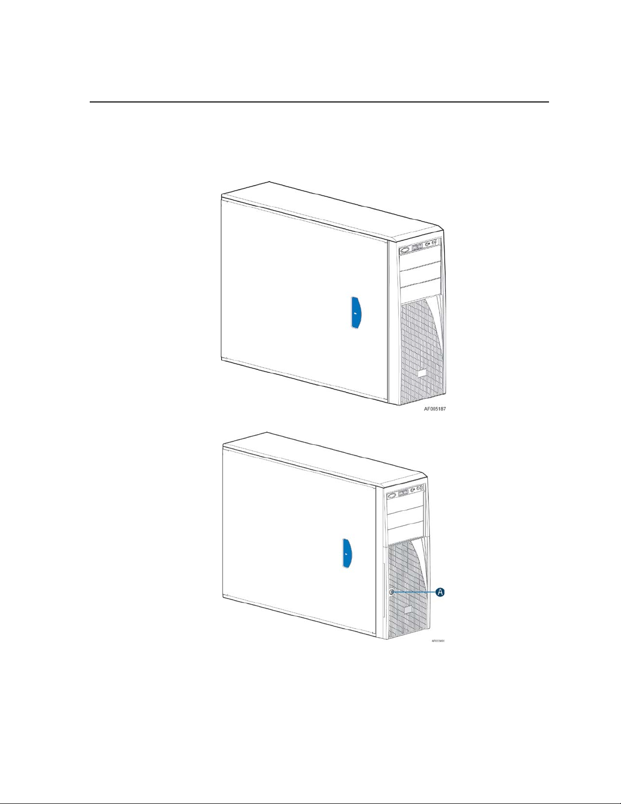
Figure 1. Chassis Front View for Fixed Hard Drive
A. Front Door Lock
Figure 2. Chassis Front View for Hotswap Hard Drive
®
Intel
Server Chassis P4000M Service Guide 1
Page 16
Server Chassis Features
Feature
Description
Dimensions
17.2'' high
Hard Drives Options
Up to eight fixed HDDs
Peripherals
Three multi-mount 5.25 peri pheral bays
Control Panel (dependent
Front Panel
LEDs and displays
With Front Panel
o
Power Supply Options
One fixed 550-W
Cooling Options
Non redundant cooling solution: One fixed system CPU zone fan + One fixed
USB 2.0
Two front panel USB ports with Front Panel
Video
One rear panel video port
Chassis Features
Table 1. Intel® Server Chassis P4000M family Base Feat ures
on option selected)
6.8'' wide
25'' deep (without bezel: 24.5'')
4x 3.5'' SATA/SAS Hot Swap Hard Drive Bays
8x 3.5'' SATA/SAS Hot Swap Hard Drive Bay
8x2.5'' SATA/SAS Hot Swap Hard Drive Bay
Two 8x2.5'' SATA/SAS Hot Swap Hard Drive Bays
Intel® Local Control Panel (Optional)
(dependent on option
selected)
o NIC1 Activity
o NIC2 Activity
o NIC3 Activity
o NIC4 Activity
o Power/Sleep
o System Status
o System Chassis Identification
Hard Drive Activity
One hotswap 750W with high current PDB
Two hotswap 750-W common redundant power supply with high current PDB
One hotswap 460-W with low c urrent PDB
Two hotswap 460-W common redundant power supply with low current PDB
Two hotswap 1200-W common redundant power supply with high current
PDB
system PCI zone fan
Redundant cooling solution: Five hotswap syste m fans
Four Back panel USB ports (depending on server/workstation board)
2 Intel
®
Server Chassis P4000M Service Guide
Page 17
Component Identification
Server Chassis Features
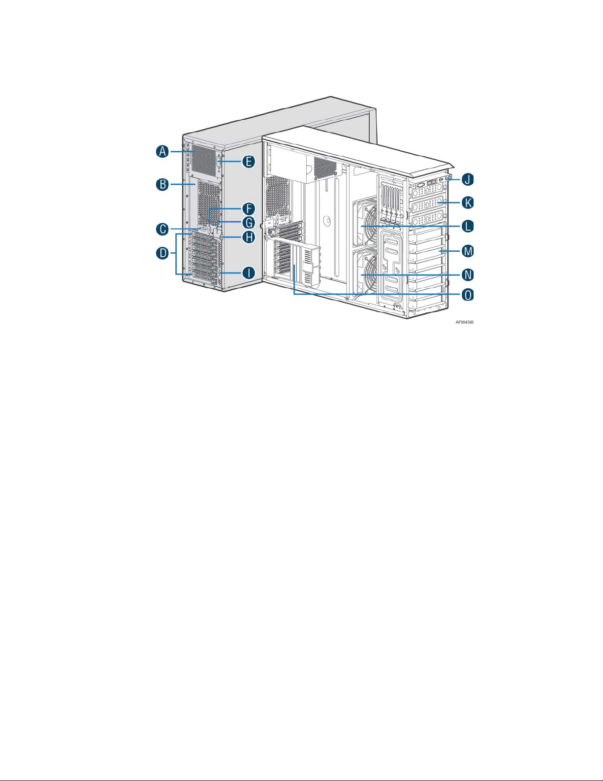
A. Fixed Power supply
B. I/O Ports
C. Alternate RMM4 Knockout
D. PCI Add-in Board Slot Covers
E. AC Input Power Connector
F. Serial Port Knockout
G. A Kensington* Cable Lock Mounting Hole
H. Padlock Loop
I. Alternate RMM4 Knockout
J. Front Panel
K. 5.25'' Peripheral Bays
L. CPU Zone System Fan (Fan 2)
M. Fixed Hard Drive Carrier Tray
N. PCI Zone System Fan (Fan 1)
O. PCI card retainer
Figure 3. Internal Chassis View of Intel® Server Chassis P4000M with Fixed Power Supply,
Fixed Hard Drives, Fixed System Fans
®
Intel
Server Chassis P4000M Service Guide 3
Page 18
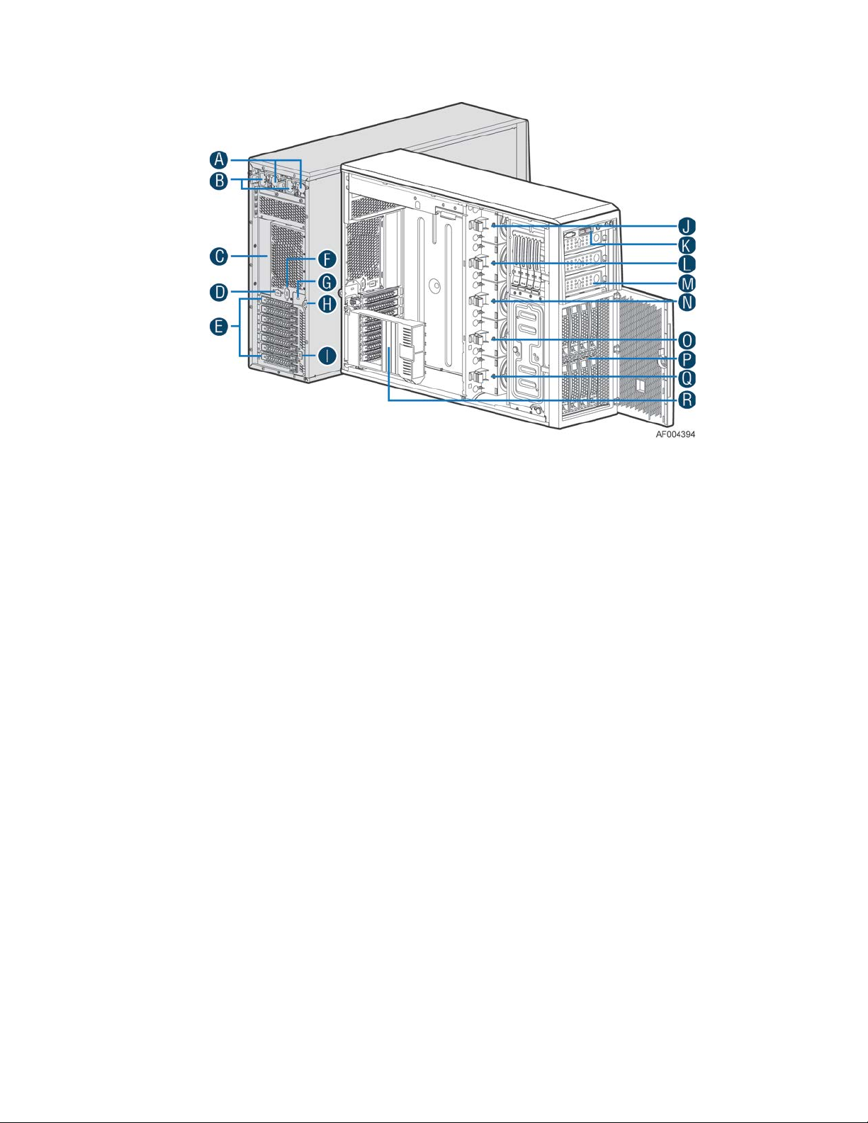
Server Chassis Features
A. Two Redundant Hotswap Power Supply
B. AC Input Power Connector
C. I/O Ports
D. Alternate RMM4 Knockout
E. PCI Add-in Board Slot Covers
F. Serial Port Knockout
G. A Kensington* Cable Lock Mounting Hole
H. Padlock Loop
I. Alternate RMM4 Knockout
J. Hotswap System Fan 5
K. Front Panel
L. Hotswap System Fan 4
M. 5.25'' Peripheral Bays
N. Hotswap System Fan 3
O. Hotswap System Fan 2
P. 8x3.5'' Hotswap HDD Cage
Q. Hotswap System Fan 1
R. PCI card retainer
Figure 4. Internal Chassis View of Intel® Server Chassis P000M with Hotswap Power Supply,
Hotswap Hard Drives and Hotswap System Fans
4 Intel
®
Server Chassis P4000M Service Guide
Page 19
Server Chassis Features
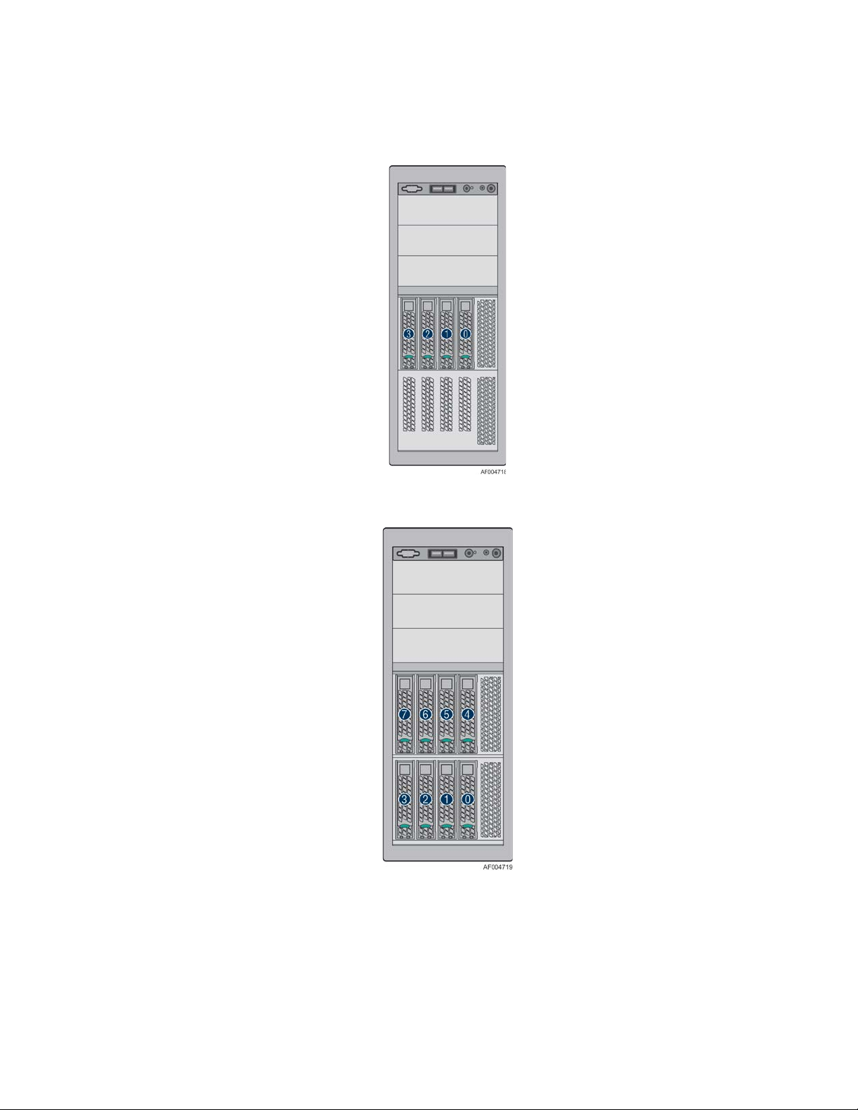
Hot Swap Hard Drive Bay Options and HDD Numbering
Figure 5. 4x3.5'' Hotswap Drive Cage
Figure 6. 8x3.5'' Hotswap Drive Cage
®
Intel
Server Chassis P4000M Service Guide 5
Page 20
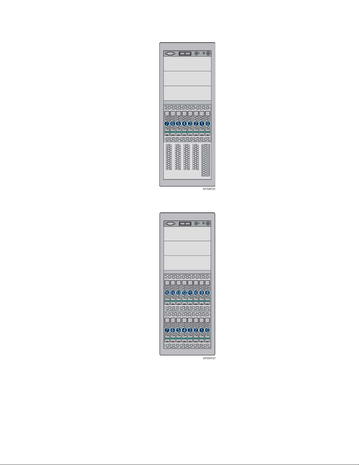
Server Chassis Features
Figure 7. 8x2.5'' Hotswap Drive Cage
Figure 8. Two 8x2.5'' Hotswap Drive Cages
Front Panel
The Intel® Server Chassis P4000M fam ily uses a common front control panel. The layout of the
front control panel is as shown in below figure.
®
6 Intel
Server Chassis P4000M Service Guide
Page 21

Figure 9. Front Panel Controls and Indicators
Green
On
Power on or S0 sleep.
Green
Blink
S1 sleep or S3 standby only for workstation baseboards.
Off
Off (also sleep S4/S5 modes).
Green
On
System ready/No alarm.
System ready, but degraded: redundancy lost such as PS or
Critical alarm: Voltage, thermal, or power fault; CPU
Non-Critical failure: Critical temp/voltage threshold; VDR hot
AC power off: System unplugged.
Green
Blink
HDD access.
LAN 1-4
S1200BT)
Green
On
LAN link/no access.
Green
Blink
LAN access.
Blue
On
Front panel chassis ID button pressed.
Blue
Blink
Unit selected for identification via software.
The description of the front panel LED s are lis te d in th e fo llowing table:
Table 2. Front Panel LED Functionality
LED Color Condition What It Means
Server Chassis Features
Power/Sleep
Status
Global HDD
Activity
Activity/Link
(LAN 1-2 for Intel®
Server Board
Chassis
Identification
Green Blink
Amber On
Amber Blink
Off
Off No access and no fault.
Off Idle
Off No identification.
fan failure; non-criti cal temp/v oltage threshold; battery
failure; or predictive PS failure.
missing; insufficient power unit redundancy resource offset
asserted.
asserted; min number fans not present or failed.
AC power on: System powered off and in standby, no prior
degraded\non-critical\critical state.
®
Intel
Server Chassis P4000M Service Guide 7
Page 22
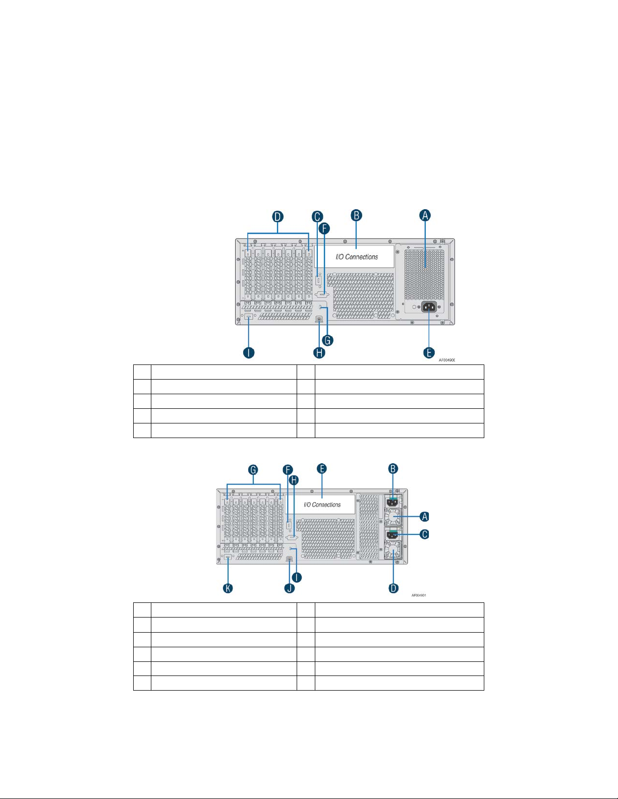
Server Chassis Features
A
Fixed Power Supply
F
Serial-B Port (Optional)
B
IO Connectors
G
Kensington* Cable Lock Mounting Hole
C
RMM4 NIC/1394B Port (Optional)
H
Padlock Loop
D
Add in PCI-e cards
I
RMM4 NIC Port (Optional)
E
Power Connector
A
Hotswap Power Supply
G
Add in PCI-e cards
B
Power Connector
H
Serial-B Port (Optional)
C
Power Connector
I
Kensington* Cable Lock Mounting Hole
D
Hotswap Power Supply
J
Padlock Loop
E
IO Connectors
K
RMM4 NIC Port (Optional)
F
RMM4 NIC/1394B Port/(Optional)
NOTE
/
This is dependent on server board support. Not all server boards support all features. For additional
details about front panel functions supported for a specific board, refer to the individual server
board specifications.
Back Panel
The following figure shows the layout of back panel with fixed power supply and hotswap
redundant power supplies:
Figure 10. Back Panel Layout (with Fixed Power Supply)
8 Intel
Figure 11. Back Panel Layout (with Hotswap Power Supply)
®
Server Chassis P4000M Service Guide
Page 23
Server Chassis Features
Hotswap SAS/SATA B ac kpla ne
The Hotswap SAS/SATA backplane serves as an interface between the motherboard and the system
drives. The following diagrams show the location for each connector found on the backplane:
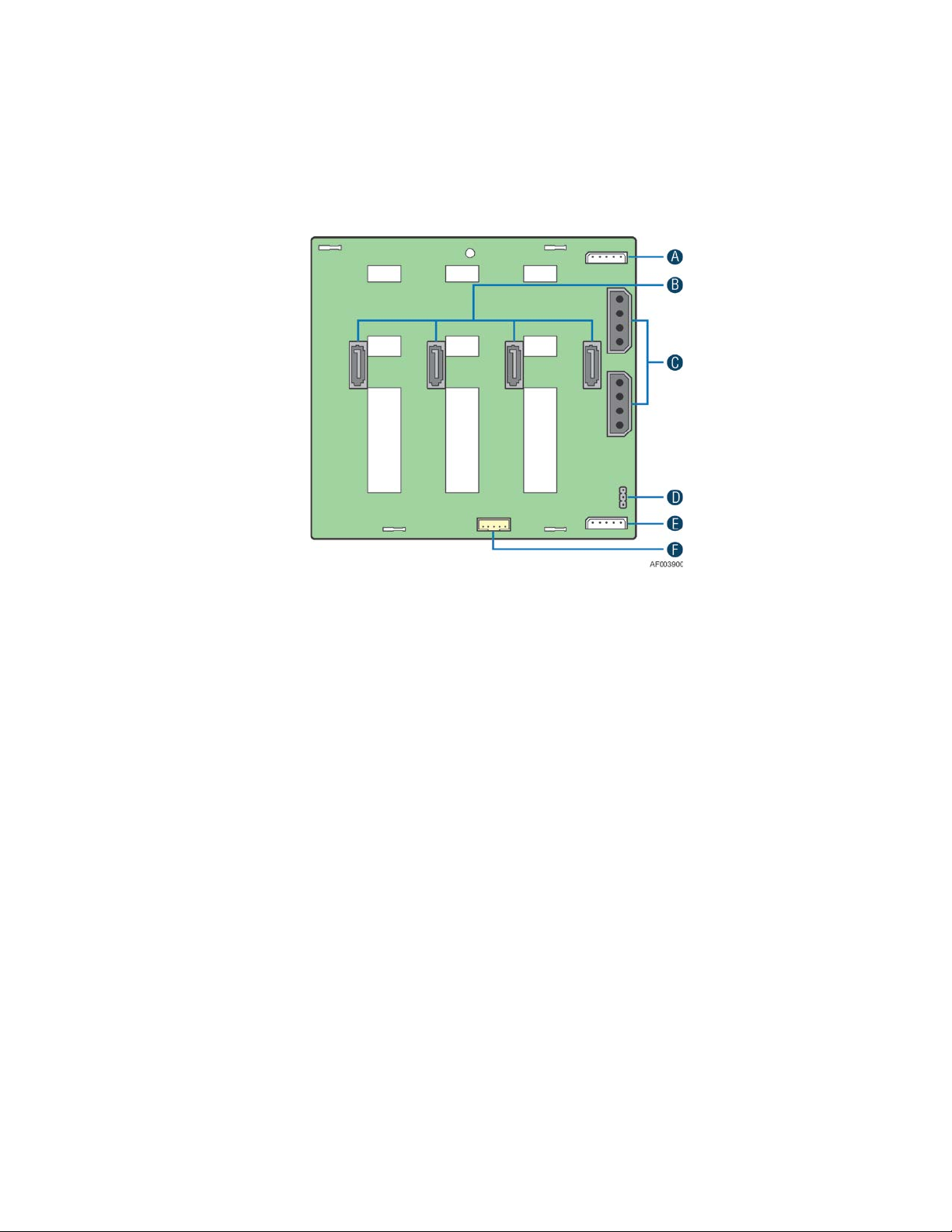
4x3.5'' Hard Drive Backplane
A. I2C_In Connectors
B. SATA/SAS Cable Connectors
C. Power Connectors
D. SATA 6X Mode Connector
E. I2C_Out Connector
F. SGPIO Connector
Figure 12. 4x3.5'' HSBP Board (Rear View)
®
Intel
Server Chassis P4000M Service Guide 9
Page 24
Server Chassis Features
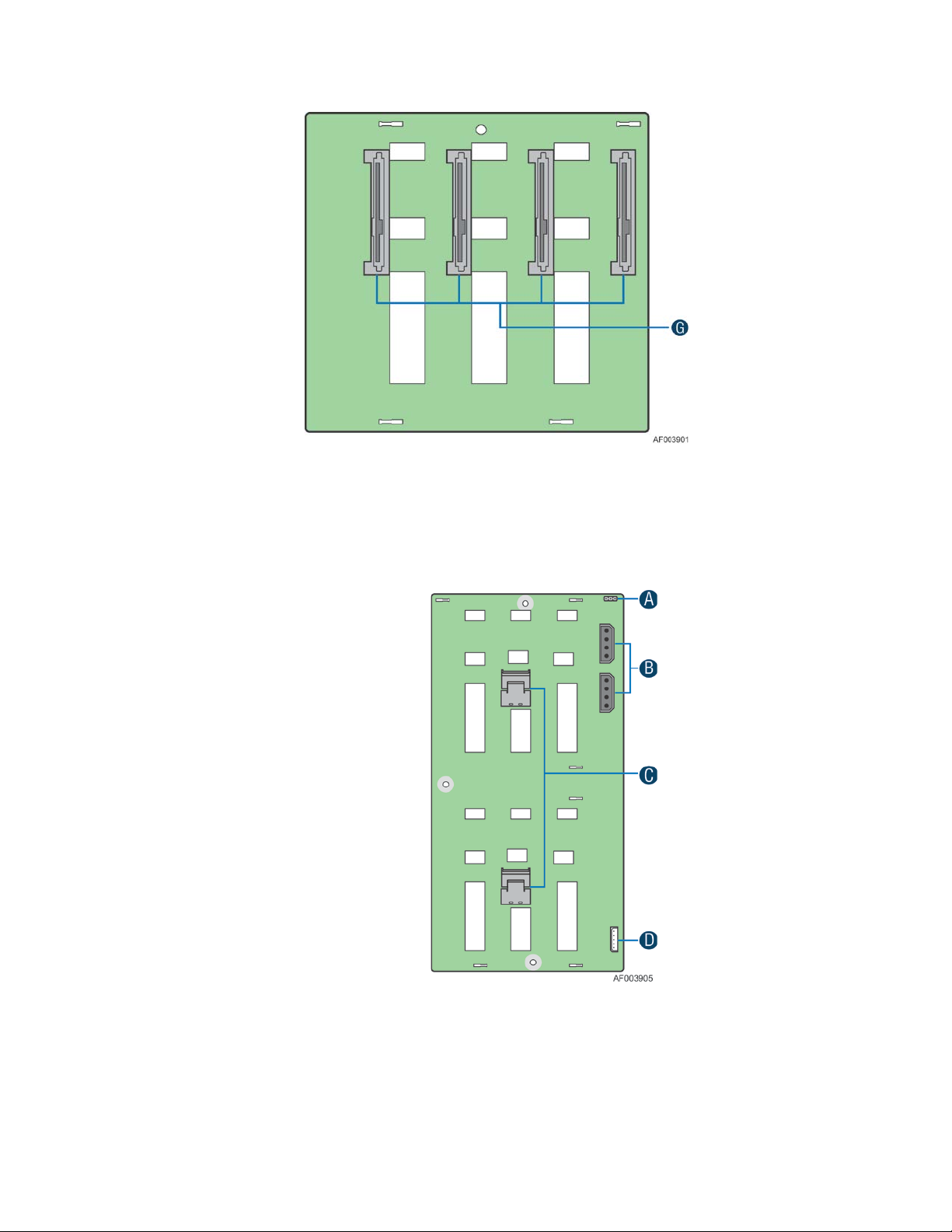
G. SATA/SAS Hotswap Drive Connectors
Figure 13. 4x3.5'' HSBP Board Layout (Front View)
8x3.5'' Hard Drive Backplane
A. SATA 6X Mode
B. Power Connectors
C. MINI_SAS Connectors
2
C Connector
D. I
Figure 14. 8x3.5'' HSBP Board (Rear View)
10 Intel
®
Server Chassis P4000M Service Guide
Page 25
Server Chassis Features
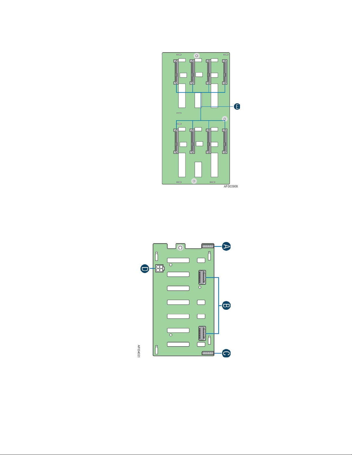
E. SATA/SAS Hotswap Drive Connectors
Figure 15. 8x3.5'' HSBP Board (Front View)
8x2.5'' Hard Drive Backplane
A. I2C_OUT Connector
B. MINI_SAS Connectors
C I2C_IN Connector
D. Power Connectors
Figure 16. 8x2.5'' HSBP Board (Front View)
®
Intel
Server Chassis P4000M Service Guide 11
Page 26
Server Chassis Features
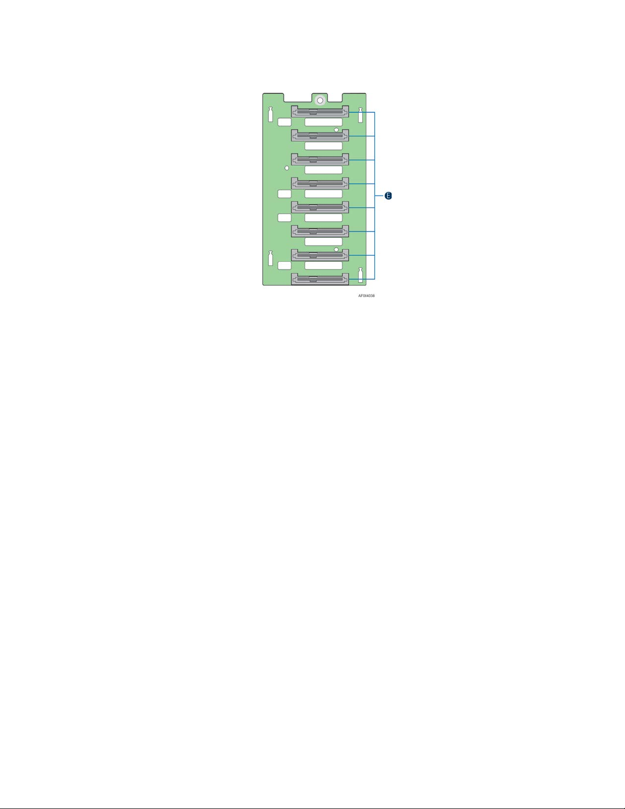
E. SATA/SAS Hotswap Drive Connectors
Figure 17. 8x3.5'' HSBP Board (Front View)
12 Intel
®
Server Chassis P4000M Service Guide
Page 27

Hardware Installations and Upgrades
2 Hardware Installations and Upgrades
Before You Begin
Before working with your server product, pay close attention to the “Appendix B: S afe ty
Information”
This document provides instructions for adding and replacing chassis components. For
instructions on replacing components on the server board, such as the processor and memory
DIMMs, see the instructions provided with the server/workstation board.
Tools and Supplies Needed
Phillips* (cross head) screwdriver (#1 bit and #2 bit)
Needle nosed pliers
Anti-static wrist strap and conductive foam pad (recommended)
System Reference
All references to left, right, front, top, and bottom assume the reader is facing the front of the
chassis as it would be positioned for normal operation.
Removing and I nstalling the Chassis Cover
Removing the Chassis Cover
The Intel® Server Chassis P4000M family must be operated with the top cover in place to
ensure proper cooling. You will need to remove the top cover to add or replace components
inside of the platform. Before removing the top cover, power down the server and unplug all
peripheral devices and the AC power cable.
NOTE
/
A non-skid surface or a stop behind the chassis may be needed to prevent the chassis from sliding on
your work surface.
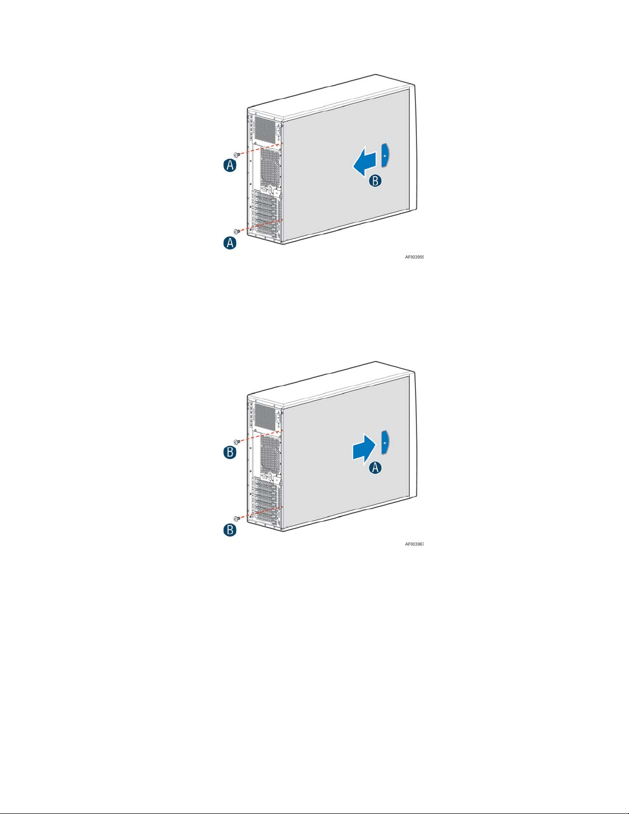
1. Observe the safety and ESD precautions at the beginning of this book.
2. Turn off all peripheral devices connected to the server. Turn off the server.
3. Disconnect the AC power cord.
4. Remove the screws (see letter A).
5. Slide the side cover back (see letter B) and lift the cover outw ard to remove it.
®
Intel
Server Chassis P4000M Service Guide 13
Page 28
Hardware Installations and Upgrades
Figure 18. Removing the Chassis Cover
Installing the Chassis Cover
1. Slide the chassis cov er on the cha ssi s ( see letter A).
2. Latch the cover securely to the chassis.
3. Secure the chassis cov er with the screws (see letter B).
Figure 19. Installing the Chassis Cover
14 Intel
®
Server Chassis P4000M Service Guide
Page 29
Hardware Installations and Upgrades
Removing and Installing the Front Bezel (Pedestal Only)
Removing the Front Bezel (Pedestal Only)
NOTE
/
For a rack configuration or chassis on its side, position the chassis hanging over the edge of a table or
workbench before removing the bezel.
There are two type of bezel assembly. One type is for fixed HDD configuration, the other type is for
Hotswap HDD configuration.
CAUTION
Do not rotate the bezel assembly more than 40 degrees or you will damage the bezel assembly.
1. Observe the safety and ESD precautions at the beginning of this book.
2. Power down the server and unplug all peripheral devices and the AC power cable.
3. Remove the chassis cover. For instructions, see “Removing the Chassis Cover”.
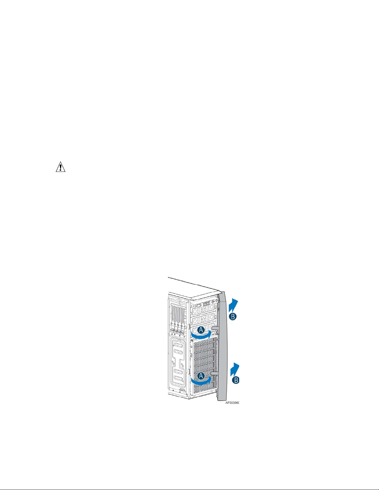
4. Release the two plastic tabs on the left side of the bezel assembly to disengage the tabs, and rotate
the bezel assembly (see letter A) no more than 40 degrees outward.
5. At a 40-degree angle, push the bezel assembly away from the chassis (see letter B).
6. If the bezel assembly does not immediately disconnect from the chassis, tap the left-hand side of the
bezel assembly to disengage the bezel hooks on the right-hand side of the chassis.
Figure 20. Removing the Front Bezel
®
Intel
Server Chassis P4000M Service Guide 15
Page 30
Hardware Installations and Upgrades
Installing the Front Bezel (Pedestal Only)
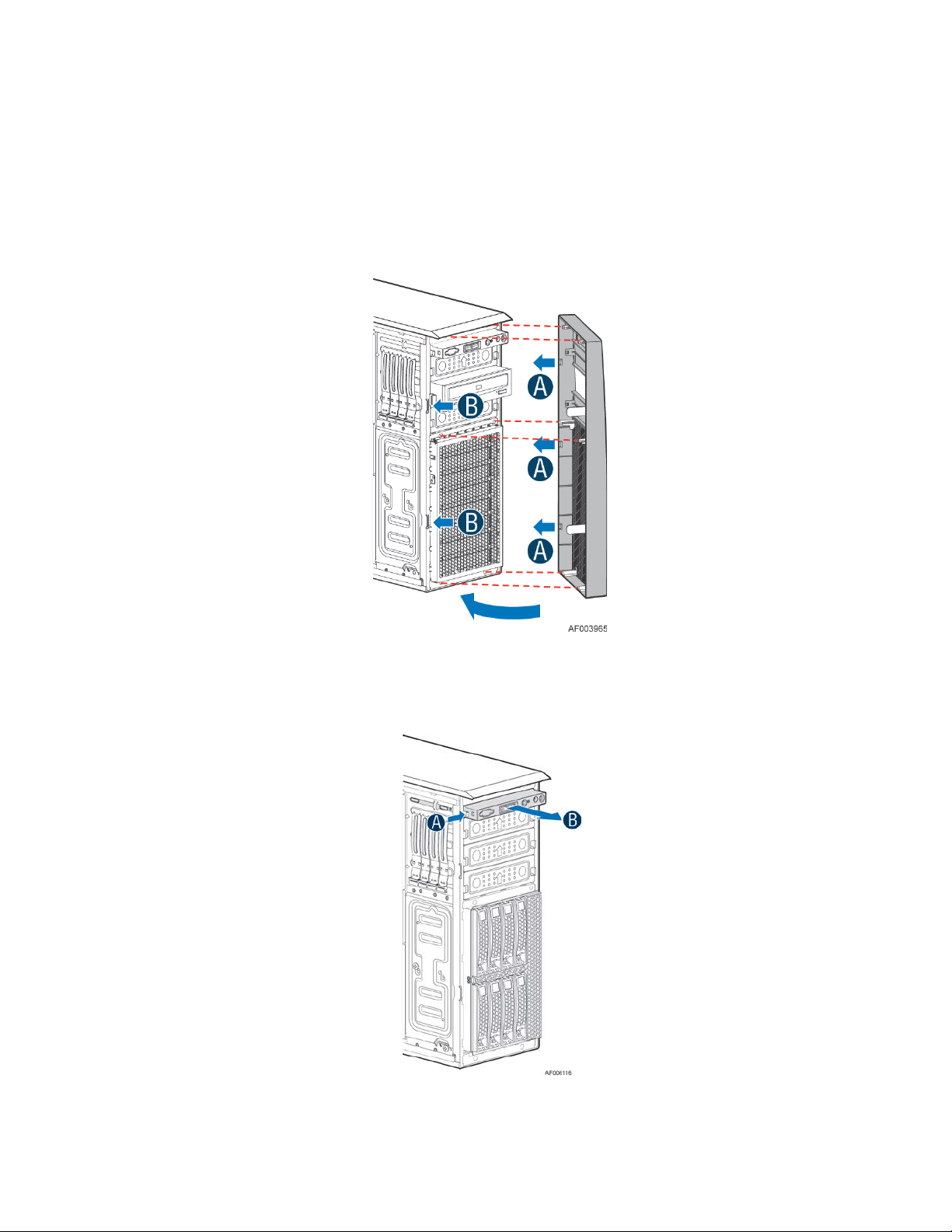
1. Fit the right edge of the bezel assembly against the right side of the chassis.
2. Engage the plastic bezel hooks (see letter A) into the raised metal slots at the chassis edge.
3. Rotate the bezel assembly toward the chassis.
4. Latch the two plastic tabs (see letter B) on the left side of the bezel assembly to the chassis.
Figure 21. Installing the Front Bezel
Converting the Pedestal Chassis to Rack Mount Chassis
1. Remove the front panel module.
Figure 22. Removing the Front Panel
16 Intel
®
Server Chassis P4000M Service Guide
Page 31

2. Remove the fillers for 5.25” drive slots if need.
Figure 23. Removing the Fille rs
Hardware Installations and Upgrades
3. Remove the cosmetic top board.
Figure 24. Removing the Top Board
4. Install the front panel module.
Figure 25. Installing the Front Panel
®
Intel
Server Chassis P4000M Service Guide 17
Page 32

Hardware Installations and Upgrades
5. Install the 5.25” drive if need.
Figure 26. Installing the Drive (optional)
6. Install the rack bezel frame
NOTE
/
The rack bezel frame is different from the pedestal bezel frame).
Figure 27. Installing the Rack Bezel frame
18 Intel
®
Server Chassis P4000M Service Guide
Page 33

7. Install the rack mount handles.
Figure 28. Installing the Rack Mount handles
8. Install the rack bezel (optional).
Hardware Installations and Upgrades
9. Lock the front bezel key.
Figure 29. Installing the Rack Bezel
Figure 30. Locking the Front Bezel key
®
Intel
Server Chassis P4000M Service Guide 19
Page 34

Hardware Installations and Upgrades
Installing and/or Removing Airduct
NOTE
/
Airduct may need to be ordered separately. See Configuration Guide of the server board for which airduct
work with your server board. The installation and/or removing airduct steps in below is generic. Please
see your board or system documents for specific instructions about installing and/or removing airduct.
Installing the Airduct
1. Observe the safety and ESD precautions at the beginning of this book.
2. Power down the server and unplug all peripheral devices and the AC power cable.
3. Remove the chassis cover. For instructions, see “Removing the Chassis Cover”.
4. Install the airduct by matching the alignment tabs on airduct and the alignment holes on chassis
bracket.
Figure 31. Installing the Airduct
20 Intel
®
Server Chassis P4000M Service Guide
Page 35

Removing the Airduct
1. Observe the safety and ESD precautions at the beginning of this book.
2. Power down the server and unplug all peripheral devices and the AC power cable.
3. Remove the chassis cover. For instructions, see “Removing the Chassis Cover”.
4. Remove the airduct.
Replacing the Fixed Fan
NOTE
/
Please pay attention to the fan cable connector color. The fan with blue co nne ctor sho uld b e instal led in
fan 2 bracket and the fan with white connector should be installed in fan 1 bracket. The fan numbering is
inscribed on the chassis.
This procedure applies only to the Intel
®
Hardware Installations and Upgrades
Server Chassis P4000M family with fixed fan configuration.
Removing the Fixe d Fan
1. Observe the safety and ESD precautions at the beginning of this book.
2. Power down the server and unplug all peripheral devices and the AC power cable.
3. Remove the chassis cover. For instructions, see “Removing the Chassis Cover”.
4. Remove the air duct if the air duct is installed. For instructions, see “Removing the Airduct”.
5. Disconnect the appropriate fan power cable from the server board (see letter A).
Figure 32. Disconnecting the fan power cable from the server board
®
Intel
Server Chassis P4000M Service Guide 21
Page 36

Hardware Installations and Upgrades
6. Remove system fan by pushing the tabs outward and disengaging from its snap-in bracket (see letter
B).
Figure 33. Removing fixed system fan from chassis
Installing the Fixed Fan
1. Observe the safety and ESD precautions at the beginning of this book.
2. Power down the server and unplug all peripheral devices and the AC power cable.
3. Remove the chassis cover. For instructions, see “Removing the Chassis Cover”.
4. Remove the air duct if the air duct is installed. For instructions, see “Removing the Airduct”.
5. Insert the fan cable in the fan brac ket as shown below (see letter A). Pay attention to the fan cable
connector color. The fan with blue fan cable connector should be installed in fan2 bracket; t he fan
with white fan connector should be installed in fan 1 bracket.
Figure 34. Inserting the fan cable in the corresponding fan bracket
22 Intel
®
Server Chassis P4000M Service Guide
Page 37

Hardware Installations and Upgrades
6. Install the fixed fan in the corresponding fan bracket (see letter B).
Figure 35. Installing the Fixed Fan
7. Connect fan power cable to the server/workstation board. See the Quick Start User’s Guide or
Service Guide provided with your Intel
®
server/workstation board for appropriate connection location.
Removing and Installing the Hotswap Fan
NOTE
/
This procedure applies only to the Intel® Server Chassis P4000M family with hotswap fan configuration.
Removing the Hotswap Fan
1. Observe the safety and ESD precautions at the beginning of this book.
2. Remove the chassis cover. For instructions, see “Removing the Chassis Cover”.
3. Press latch on fan and pull on handle to remove hotswap f an from chass is.
Figure 36. Removing Hotswap Fan
®
Intel
Server Chassis P4000M Service Guide 23
Page 38

Hardware Installations and Upgrades
Installing the Hotswap Fan
1. Observe the safety and ESD precautions at the beginning of this book.
2. Remove the chassis cover. For instructions, see “Removing the Chassis Cover”.
3. Insert hotswap fan into corresponding chassis slot until it clicks into place.
Figure 37. Installing Hotswap Fan
Removing and Installing the Fixed HDD EMI Shield
NOTE
/
For a rack configuration or chassis on its side, position the chassis hanging over the edge of a table or
workbench before removing the bezel.
This procedure applies only to the Intel
Removing the Fixed HDD EMI Shield
1. Observe the safety and ESD precautions at the beginning of this book.
2. Power down the server and unplug all peripheral devices and the AC power cable.
3. Remove the chassis cover. For instructions, see “Removing the Chassis Cover”.
4. Remove the front bezel. For instructions, see “Removing the front bezel”.
5. Press the clip (see letter A) and lift the EMI shield (see letter B) and move EMI s hield outward from
the chassis.
®
Server chassis P4000M family with fixed HDD configuration.
24 Intel
®
Server Chassis P4000M Service Guide
Page 39

Hardware Installations and Upgrades
Figure 38. Removing the Fixed HDD EMI Shield
Installing the Fixe d H DD EM I Shield
1. Fit the edges of the EMI Shield against the sides of the chassis (see letter A).
2. While pressing the clip (see letter B), slide the EMI Shield downwards until the latches on the EMI
Shield are engaged with the chassis (see letter C).
Figure 39. Installing the Fixed HDD EMI Shield
®
Intel
Server Chassis P4000M Service Guide 25
Page 40

Hardware Installations and Upgrades
Removing and Installing Fixed Hard Drive(s)
NOTE
/
This procedure applies only to the Intel® Server Chassis P4000M family with fixed HDD configuration.
Removing Fixed Hard Drive(s)
1. Observe the safety and ESD precautions at the beginning of this book.
2. Power down the server and unplug all peripheral devices and the AC power cable.
3. Remove the chassis cover. For instructions, see “Removing the Chassis Cover”.
4. Remove the front bezel if it is installed. For instructions, see “Removing the Front Bezel”.
5. Remove the Fixed HDD EMI shield. For instructions, see “Removing the Fixed HDD EMI Shield”.
6. Remove power and data cables from the hard drive connectors.
7. Pull out the HDD carrier tray.
Figure 40. Removing Fixed Hard Drives
8. Use screwdriver to release the 3.5” or 2.5” HDD from the carrier tray.
Figure 41. Removing the 3.5” HDD from Fixed HDD tray
26 Intel
®
Server Chassis P4000M Service Guide
Page 41

Figure 42. Removing the 2.5” HDD from Fixed HDD tray
9. Reinstall the HDD carrier tray into chassis.
Hardware Installations and Upgrades
Figure 43. Reinstalling the HDD Carrier Tray
10. Install the Fixed HDD EMI shield. For instructions, see “Installin g the Fixed HDD EMI Shield”.
11. Install the front bezel. For instructions, see “Installing the Front Bezel”.
12. Install the air duct if the air duct is removed. For instructions, see “Removing the Airduct”.
13. Install the chassis cover. For instructions, see “Installing the Chassis Cover”.
14. Plug all peripheral devices and the AC power cable into the server.
15. Power up the server.
Installing Fixed Hard Drive(s)
1. Observe the safety and ESD precautions at the beginning of this book.
2. Power down the server and unplug all peripheral devices and the AC power cable.
3. Remove the chassis cover. For instructions, see “Removing the Chassis Cover”.
4. Remove the front bezel if it is installed. For instructions, see “Removing the Front Bezel”.
5. Remove the Fixed HDD EMI shield. For instructions, see “Removing the Fixed HDD EMI Shield”.
®
Intel
Server Chassis P4000M Service Guide 27
Page 42

Hardware Installations and Upgrades
6. Pull out the HDD carrier tray.
7. Secure the 3.5” or 2.5” HDD on the HDD carrier tray with screws.
Figure 44. Removing Fixed Hard Drive
Figure 45. Securing the 3.5” HDD on Fixed HDD Carrier Tray
28 Intel
®
Server Chassis P4000M Service Guide
Page 43

Figure 46. Securing the 2.5” HDD on Fixed HDD Carrier Tray
8. Insert the HDD carrier tray into chassis.
Figure 47. Inserting the HDD Carrier Tray
Hardware Installations and Upgrades
9. Connect power and data cables on HDD.
10. Install the Fixed HDD EMI shield. For instructions, see “Installing the Fixed HDD EMI Shield”.
11. Install the front bezel. For instructions, see “Installing the Front Bezel”.
12. Install the air duct if the air duct is removed. For instructions, see “I nstalling the Airduct”
13. Install the chassis cover. For instructions, see “Installing the Chassis Cover”.
14. Plug all peripheral devices and the AC power cable into the server.
15. Power up the server.
Removing and I nstalling 4x3.5” Hotswap Hard Drive Cage Assembly
NOTE
/
This procedure applies only to the Intel® Server Chassis P4000M family with 4x3.5'' hotswap hard disk
drive cage configuration.
Removing 4x3.5” Hotswap Hard Drive Cage with Backplane
1. Observe the safety and ESD precautions at the beginning of this book.
2. Power down the server and unplug all peripheral devices and the AC power cable.
3. Remove the chassis cover. For instructions, see “Removing the Chassis Cover”.
4. Remove the front bezel if it is installed. For instructions, see “Removing the Front Bezel”.
5. Disconnect the power and data cables to the backplane.
®
Intel
Server Chassis P4000M Service Guide 29
Page 44

Hardware Installations and Upgrades
6. Use screwdriver to release the hotswap hard drive cage (see letter A) from the chassis and remove
the hotswap hard drive cage (see letter B).
7. Lift the EMI shi eld (see letter A) and move EMI shield outward from the chassis (see letter B).
Figure 48. Removing the 4x3.5” HDD Cage
Figure 49. Removing the EMI shield
Installing 4x3.5'' Hotswap Hard Drive Cage with Backplane
CAUTION
It is critical that you connect the SAS/SATA data cables correctly from the SAS/SATA backplane to
your server board or RAID controller card. Failure to do so may result in data loss.
1. Observe the safety and ESD precautions at the beginning of this book.
2. Power down the server and unplug all peripheral devices and the AC power cable.
3. Remove the chassis cover. For instructions, see “Removing the Chassis Cover”.
4. Remove the front bezel if it is installed. For instructions, see “Removing the Front Bezel”.
5. Install the hotswap EMI HDD shield under the hotswap cage.
®
30 Intel
Server Chassis P4000M Service Guide
Page 45

Hardware Installations and Upgrades
1) Fit the edges of the EMI shield against the sides of the chassis (see letter A).
2) While pressing the EMI shield, slide the EMI Shield downwards until the latches on the EMI
shield are engaged with the chassis (see letter B).
Figure 50. Installing the EMI shield
6. Install the 4x3.5'' Hotswap Hard Drive Cage.
1) Slide the 4x3.5'' Hotswap Drive Cage into the slot (see letter A).
2) Secure the Hard Drive Cage with the Screw (see letter B).
Figure 51. Installing the 4x3.5'' Hotswap Hard Drive Cage
7. Make the backplane and server board/RAID controller card cable connec tio ns. Re fer t o the
documentation that came with your server board and/or RAID controller card for instructions on
connecting backplane cables to your server board or RAID controller card.
1) Connect data cables (letter A).
2) Connect an I2C_IN cable (letter B).
3) Connect an SGPIO cable (letter C).
®
Intel
Server Chassis P4000M Service Guide 31
Page 46

Hardware Installations and Upgrades
4) Connect power cable (letter D).
Figure 52. 4x3.5'' Hot Swap Backplane Cable Connections
16. Install the front bezel. For instructions, see “Installing the Front Bezel”.
17. Install the chassis cover. For instructions, see “Installing the Chassis Cover”.
18. Plug all peripheral devices and the AC power cable into the server.
19. Power up the server.
Removing and Installing 4x3.5'' Hotswap Backplane
Removing 4x3.5'' Hotswap Backplane
1. Observe the safety and ESD precautions at the beginning of this book.
2. Power down the server and unplug all peripheral devices and the AC power cable.
3. Remove the chassis cover. For instructions, see “Removing the Chassis Cover”.
4. Remove the front bezel if it is installed. For instructions, see “Removing the Front Bezel”.
5. Remove the 4x3.5'' Hotswap Hard drives cage. For instructions, see “Removing 4x3.5'' Hotswap Hard
Drive Cage”.
6. Remove the screw on the backplane (see letter A).
7. Push the backplane (see letter B) and remove the backplane from the chassis (see letter C).
32 Intel
®
Server Chassis P4000M Service Guide
Page 47

Figure 53. Removing 4x3.5'' Hotswap Backplane
Installing 4x3.5” Hotswap Backplane
Hardware Installations and Upgrades
1. Observe the safety and ESD precautions at the beginning of this book.
2. Power down the server and unplug all peripheral devices and the AC power cable.
3. Remove the chassis cover. For instructions, see “Removing the Chassis Cover”.
4. Remove the front bezel if it is installed. For instructions, see “Removing the Front Bezel”.
5. Remove the 4x3.5'' Hotswap Hard drives cage. For instructions, see “Removing 4x3.5'' Hotswap Hard
Drive Cage”.
6. Attach the backplane to the back side of the hotswap drive cage, and make sure the hooks on the
cage are inserted in the backpl ane hole s (see letter A).
7. Push the backplane (see letter B) and secure the backplane with the screw (see letter C).
Figure 54. Installing 4x3.5” Hotswap Backplane
8. Install the 4x3.5'' Hotswap Hard drives cage. For instructions, see “installing 4x3.5'' Hotswap Hard
Drive Cage”.
9. Install the front bezel. For instructions, see “Installing the Front Bezel”.
®
Intel
Server Chassis P4000M Service Guide 33
Page 48

Hardware Installations and Upgrades
10. Install the chassis cover. For instructions, see “Installing the Chassis Cover”.
11. Plug all peripheral devices and the AC power cable into the server.
12. Power up the server.
Removing and Installing 8x3.5'' Hotswap Hard Drive Cage Assembly
NOTE
/
This procedure applies only to the Intel® Server Chassis P4000M family with 8x3.5'' hotswap hard disk
drive cage configuration.
Removing 8x3.5'' Hotswap Hard Drive Cage Assembly
1. Observe the safety and ESD precautions at the beginning of this book.
2. Power down the server and unplug all peripheral devices and the AC power cable.
3. Remove the chassis cover. For instructions, see “Removing the Chassis Cover”.
4. Remove the front bezel if it is installed. For instructions, see “Removing the Front Bezel (Pedestal
Only)”.
5. Disconnect the power and data cables to the backplane.
6. Use screwdriver to release the hotswap hard drive cage (see letter A) from the chassis and remove
the hotswap hard drive cage (see letter B).
Figure 55. Removing the 8x3.5'' Hotswap HDD Cage Assembly
34 Intel
®
Server Chassis P4000M Service Guide
Page 49

Hardware Installations and Upgrades
Installing 8x3.5'' Hotswap Hard Drive Cage Assembly
CAUTION
It is critical that you connect the SAS/SATA data cables correctly from the SAS/SATA backplane to
your server board or RAID controller card. Failure to do so may result in data loss.
1. Observe the safety and ESD precautions at the beginning of this book.
2. Power down the server and unplug all peripheral devices and the AC power cable.
3. Remove the chassis cover. For instructions, see “Removing the Chassis Cover”.
4. Remove the front bezel if it is installed. For instructions, see “Removing the Front Bezel (Pedestal
Only)”.
5. Install the 8x3.5'' Hotswap Hard Drive Cage.
1) Slide the 8x3.5'' Hotswap Drive Cage into the slot (see letter A).
2) Secure the Hard Drive Cage with the Screw (see letter B).
Figure 56. Installing the 8x3.5'' Hotswap Hard Drive Cage Assembly
6. Make the backplane and server board/RAID controller card cable connections. Refer to the
documentation for your server board and/or RAID controller card for instructions on connecting
backplane cables to your server board or RAID controller card.
1) Connect an I2C cable (letter A).
2) Connect Mini SAS data cables (letter B).
3) Connect power cable (letter C).
®
Intel
Server Chassis P4000M Service Guide 35
Page 50

Hardware Installations and Upgrades
Figure 57. 8x3.5'' Hot Swap Backplane Cable Connections
7. Install the front bezel. For instructions, see “Installing the Front Bezel (Pedestal Only)”.
8. Install the air duct if the air duct is removed. For instructions, see “Installing the A irdu ct ”.
9. Install the chassis cover. For instructions, see “Installing the Chassis Cover”.
10. Plug all peripheral devices and the AC power cable into the server.
11. Power up the server.
Removing and Installing 8x3.5'' Hotswap Backplane
NOTE
/
This procedure applies only to the Intel® Server Chassis P4000M family with 8x3.5'' hotswap hard
disk drive cage configuration.
Removing 8x3.5'' Hotswap Backplane
1. Observe the safety and ESD precautions at the beginning of this book.
2. Power down the server and unplug all peripheral devices and the AC power cable.
3. Remove the chassis cover. For instructions, see “Removing the Chassis Cover”.
4. Remove the front bezel if it is installed. For instructions, see “Removing the Front Bezel (Pedestal
Only)”.
5. Remove the 8x3.5'' Hotswap Hard drives cage. For instructions, see “Removing 8x3.5'' Hotswap Hard
Drive Cage Assembly”.
6. Remove all hotswap drive carriers, regardless of whether or not a drive is installed in the carrier.
7. Remove the screws on the backplane (see letter A).
8. Push the backplane (see letter B) and remove the backplane from the cage (see letter C).
36 Intel
®
Server Chassis P4000M Service Guide
Page 51

Hardware Installations and Upgrades
Figure 58. Removing 8x3.5” Hotswap Backplane
Installing 8x3.5'' Hotswap Backplane
1. Remove all hotswap drive carriers, regardless of whether or not a drive is installed in the carrier.
2. Attach the backplane to the back side of the hotswap drive cage, and make sure the hooks on the
cage are inserted in the backpl ane hole s (see letter A).
3. Push the backplane (see letter B) and secure the backplane with the screw (see letter C).
Figure 59. Installing 8x3.5'' Hotswap Backplane
®
Intel
Server Chassis P4000M Service Guide 37
Page 52

Hardware Installations and Upgrades
4. Install the 8x3.5'' Hotswap Hard drives cage. For instructions, see “installi ng 8x3.5'' Hotswap Hard
Drive Cage Assembly”.
5. Install the front bezel. For instructions, see “Installing the Front Bezel (Pedestal Only)”.
6. Install the air duct if the air duct is removed. For instructions, see “Installing the A irdu ct ”.
7. Install the chassis cover. For instructions, see “Installing the Chassis Cover”.
8. Plug all peripheral devices and the AC power cable into the server.
9. Power up the server.
Removing and Installing 8x2.5'' Hotswap Hard Drive Cage Assembly
NOTE
/
This procedure applies only to the Intel® Server Chassis P4000M family with 8x2.5'' hotswap hard disk
drive cage configuration.
Removing 8x2.5'' Hotswap Hard Drive Cage Assembly
1. Observe the safety and ESD precautions at the beginning of this book.
2. Power down the server and unplug all peripheral devices and the AC power cable.
3. Remove the chassis cover. For instructions, see “Removing the Chassis Cover”.
4. Remove the front bezel if it is installed. For instructions, see “Removing the Front Bezel (Pedestal
Only)”.
5. Disconnect the power and data cables to the backplane.
6. Use screwdriver to r elease the hotswap hard drive cage (see letter A) from the chassis and remove
the hotswap hard drive cage (see letter B).
Figure 60. Removing the 8x2.5'' HDD Cage Assembly
38 Intel
®
Server Chassis P4000M Service Guide
Page 53

Hardware Installations and Upgrades
Installing 8x2.5'' Hotswap Hard Drive Cage Assembly
CAUTION
It is critical that you connect the SAS/SATA data cables correctly from the SAS/SATA backplane to
your server board or RAID controller card. Failure to do so may result in data loss.
1. Observe the safety and ESD precau tion s at the beginn ing of t his book.
2. Power down the server and unplug all peripheral devices and the AC power cable.
3. Remove the chassis cover. For instructions, see “Removing the Chassis Cover”.
4. Remove the front bezel if it is installed. For instructio ns, see “R emov ing the Front B ez el (Pedestal
Only)”.
5. Install the 8x2.5'' Hotswap Hard Drive Cage.
1) Slide the 8x2.5” Hotswap Drive Cage into the slot (see letter A).
2) Secure the Hard Drive Cage with the Screw (see letter B).
Figure 61. Installing the 8x2.5'' Hotswap Hard Drive Cage Assembly
6. Make the backplane and server board/RAID controller card cable connections. Refer to the
documentation that came with your server board and/or RAID controller card for instructions on
connecting backplane cables to your server board or RAID controller card.
1) Connect an I2C_IN cable (letter A).
2) Connect MiniSAS data cables (letter B). There are multiple MiniSAS conn ect ors on the
backplane. The figure show connecting to one of them. Connect them as needed.
3) Connect power cable (letter C).
®
Intel
Server Chassis P4000M Service Guide 39
Page 54

Hardware Installations and Upgrades
Figure 62. 8x2.5” Hot Swap Backplane Cable Connections
7. Install the front bezel. For instructions, see “Installing the Front Bezel (Pedestal Only)”.
8. Install the air duct if the air duct is removed. For instructions, see “Installing the A irdu ct ”
9. Install the chassis cover. For instructions, see “Installing the Chassis Cover”.
10. Plug all peripheral devices and the AC power cable into the server.
11. Power up the server.
Removing and Installing the Hotswap HDD EMI Shield
NOTE
/
This procedure applies only to the Intel® Server Chassis P4000M family with 8x2.5'' hotswap hard disk
drive cage configuration.
Removing the Hotswa p HDD EMI Shield
1. Observe the safety and ESD precautions at the beginning of this book.
2. Power down the server and unplug all peripheral devices and the AC power cable.
3. Remove the chassis cover. For instructions, see “Removing the Chassis Cover”.
4. Remove the front bezel. For instructions, see “Removing the front bezel (Pedestal Only)”.
5. Remove the 8x2.5'' Hotswap HDD cage. For instructions, see “Removing 8x2.5'' Hotswap Hard Disk
Drive Cage with Backplane”
6. Lift the EMI shield (see letter A) and move EMI shield outward from the chassis (see lett er B).
40 Intel
®
Server Chassis P4000M Service Guide
Page 55

Hardware Installations and Upgrades
Figure 63. Removing the Hotswap HDD EMI Shield
Installing the Hotswap HDD EMI Shield
1. Fit the edges of the EMI Shield against the sides of the chassis (see letter A).
2. While pressing the EMI Shield, slide the EMI Shield downwards until the latches on the EMI Shield
are engaged with the chassis (see letter B).
Figure 64. Installing the Hotswap HDD EMI Shield
®
Intel
Server Chassis P4000M Service Guide 41
Page 56

Hardware Installations and Upgrades
Removing and Installing Second 8x2.5'' Hotswap Hard Disk Drive Cage Assembly
NOTE
/
This procedure applies only to the Intel® Server Chassis P4000M family with two 8x2.5'' hotswap hard disk
drive cage configuration.
Removing Second 8x2.5'' Hotswap Hard Disk Drive Cage Assembly
1. Observe the safety and ESD precautions at the beginning of this book.
2. Power down the server and unplug all peripheral devices and the AC power cable.
3. Remove the chassis cover. For instructions, see “Removing the Chassis Cover”.
4. Remove the front bezel if it is installed. For instructions, see “Removing the Front Bezel (Pedestal
Only)”.
5. Disconnect the power and data cables to the backplane.
6. Use screwdriver to release the hotswap hard drive cage (see letter A) from the chassis and remove
the hotswap hard drive cage (see letter B).
Figure 65. Removing the bottom 8x2.5 '' Hotswap HDD Cage Assembly
42 Intel
®
Server Chassis P4000M Service Guide
Page 57

Hardware Installations and Upgrades
Installing Second 8x2.5'' Hotswap Hard Disk Drive Cage Assembly
CAUTION
It is critical that you connect the SAS/SATA data cables correctly from the SAS/SATA backplane to
your server board or RAID controller card. Failure to do so may result in data loss.
1. Observe the safety and ESD precautions at the beginning of this book.
2. Power down the server and unplug all peripheral devices and the AC power cable.
3. Remove the chassis cover. For instructions, see “Removing the Chassis Cover”.
4. Remove the front bezel if it is installed. For instructio ns, see “Remov ing the Fr ont Bez el (Pedestal
Only)”.
5. Install bottom 8x2.5'' Hotswap Hard Drive Cage.
1) Slide the 8x2.5'' Hotswap Drive Cage into the slot (see letter A).
2) Secure the Hard Drive Cage with the Screw (see letter B).
Figure 66. Installing the Second 8x2.5'' Hotswap Hard Drive Cage Assembly
6. Make the backplane and server board/RAID controller card cable connections. Refer to the
documentation that came with your server board and/or RAID controller card for instructions on
connecting backplane cables to your server board or RAID controller card.
1) Connect an I2C cable to the I2C_IN connector of the bottom backplane (see letter A)
2) Connect MiniSAS data cables to the Mini SAS connector of the backplane (see letter B). There
are multiple MiniSAS connectors on the backplanes. The figure show connecting to one of them.
Connect them as needed.
3) Connect power cable to the power connector (see letter C).
4) Connect an I
connector of the top backplane (see letter D).
5) Install the front bezel. For instructions, see “Install ing the Front Bezel (Pedestal Only)”.
2
C cable to the I2C_OUT connector of the bottom backplane and the I2C_IN
®
Intel
Server Chassis P4000M Service Guide 43
Page 58

Hardware Installations and Upgrades
Figure 67. Two 8x2.5” Hot Swap Backplane Cable Connections
7. Install the air duct if the air duct is removed. For instructions, see “Installing the A irdu ct ”.
8. Install the chassis cover. For instructions, see “Installing the Chassis Cover”.
9. Plug all peripheral devices and the AC power cable into the server.
10. Power up the server.
Removing and Installing 8x2.5'' Hotswap Backplane
Removing 8x2.5'' Hotswap Backplane
1. Observe the safety and ESD precautions at the beginning of this book.
2. Power down the server and unplug all peripheral devices and the AC power cable.
3. Remove the chassis cover. For instructions, see “Removing the Chassis Cover”.
4. Remove the front bezel if it is installed. For instructions, see “Removing the Front Bezel (Pedestal
Only)”.
5. Remove the 8x2.5'' Hotswap Hard drives cage. For instructions, see “Removing 8x2.5'' Hotswap Hard
Drive Cage Assembly”.
6. Remove the screw on the backplane (see letter A).
7. Push the backplane (see letter B) and remove the backplane from the cage (see letter C).
44 Intel
®
Server Chassis P4000M Service Guide
Page 59

Hardware Installations and Upgrades
Figure 68. Removing 8x2.5'' Hotswap Backplane
Installing 8x2.5'' Hotswap Backplane
1. Attach the backplane to the back side of the hotswap drive cage, and make sure the hooks on the
cage are inserted in the backpl ane hole s (see letter A).
2. Push the backplane (see letter B) and secure the backplane with the screw (see letter C).
Figure 69. Installing 8x2.5'' Hotswap Backplane
®
Intel
Server Chassis P4000M Service Guide 45
Page 60

Hardware Installations and Upgrades
3. Install the 8x2.5'' Hotswap Hard drives cage. For instruct ions, see “Installing 8x2.5'' Hotswap Hard
Drive Cage Assembly”.
4. Install the front bezel. For instructions, see “Installing the Front Bezel (Pedestal Only)”.
5. Install the air duct if the air duct is removed. For instructions, see “Installing the A irdu ct ”.
6. Install the chassis cover. For instructions, see “Installing the Chassis Cover”.
7. Plug all peripheral devices and the AC power cable into the server.
8. Power up the server.
Installing Hotswap Hard Drive
Installing 3.5" Hotswap Hard Disk Drive
NOTE
/
This procedure applies only to the Intel® Server Chassis P4000M family with 3.5'' hotswap hard disk drive
cage configuration.
1. Open the Hotswap HDD door
2. Remove the drive carrier by pressing the green button and opening the lever (see letter A). Then slide the
carrier out (see letter B).
Figure 70. Sliding the 3.5'' HDD carrier out
46 Intel
®
Server Chassis P4000M Service Guide
Page 61

Hardware Installations and Upgrades
3. Remove the four screws securing the 3.5" HDD interface bracket and remove the 3.5" HDD interface
bracket.
Figure 71. Removing the 3.5" HDD interface bracket from Carrier
4. Install the 3.5" hard disk drive using the same four screws as shown. Make sure the connector end of the
drive matches the backplane connector.
Figure 72. Installing the 3.5" HDD into the Carrier
®
Intel
Server Chassis P4000M Service Guide 47
Page 62

Hardware Installations and Upgrades
5. With the lever open, insert the hard disk drive assembly into the cage open ing and pu sh unti l the locking
lever engages (see letter A).
6. Push in the lever to lock it into place (see letter B).
Figure 73. Sliding the 3.5" HDD Carrier into the Chassis
7. Close the HS HDD door.
Installing 2.5" Hotswap Hard Disk Drive in 3.5'' HDD Carrier
1. Remove the four screws securing the 3.5" HDD interface bracket and remove the 3.5" HDD interface
bracket.
Figure 74. Removing the 3.5" HDD interface bracket from Carrier
48 Intel
®
Server Chassis P4000M Service Guide
Page 63

Hardware Installations and Upgrades
2. Break off the tab on the 3.5" HDD interface bracket (see letter B).
Figure 75. Breaking off the tab on the bracket
3. Install the 2.5" Hard Drive Interface Bracket from top. Secure the bracket using the same screws as
shown.
Figure 76. Installing 2.5" HDD interface bracket into Carrier
®
Intel
Server Chassis P4000M Service Guide 49
Page 64

Hardware Installations and Upgrades
4. Slide the 2.5" HDD into the bracket to align the screw holes with the right and left rail (See figure D).
Secure the hard disk drive using the screws for the 2.5'' HDD (See figure E).
Figure 77. Installing the 2.5" HDD into carrier
50 Intel
®
Server Chassis P4000M Service Guide
Page 65

Hardware Installations and Upgrades
Installing 2.5" Hotswap Hard Disk Drive in 2.5'' HDD Carrier
1. Open the Hotswap HDD door.
2. Remove the drive carrier by pressing the green latch to unlock and pull out the black lever (see letter A).
3. Slide the carrier out (see letter B).
Figure 78. Sliding the 2.5'' HDD Carrier from the chassis
4. Remove the four screws securing the plastic retention drive from the 2.5'' HDD carrier (see letter C)
5. Disengage the plastic retention device from the HDD carrier (see letter D).
6. Remove the plastic retention device from the 2.5'' HDD carrier (see letter E).
Figure 79. Removing the plastic retention device from Carrier
®
Intel
Server Chassis P4000M Service Guide 51
Page 66
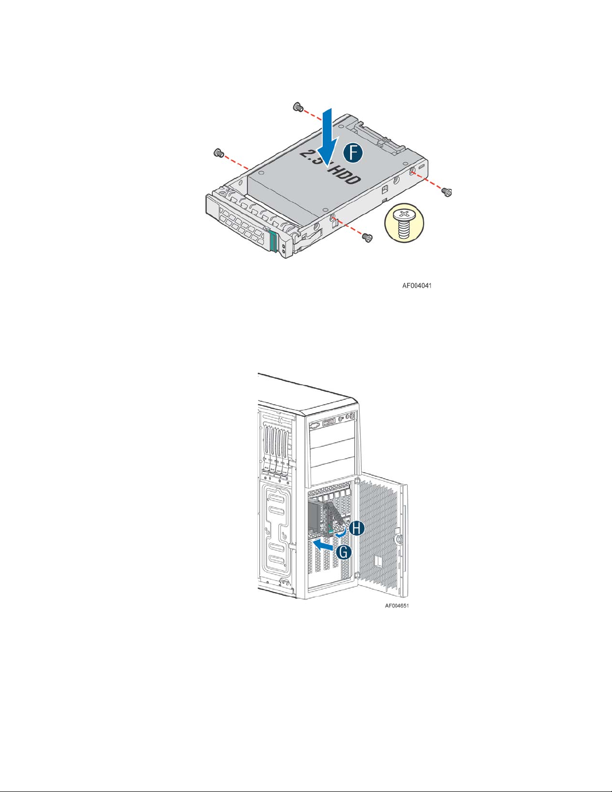
Hardware Installations and Upgrades
7. Install the 2.5" hard disk drive using the same four screws as shown. Make sure the connector end of the
drive matches the backplane connector (see letter F).
Figure 80. Installing the 2.5'' HDD in Carrier
8. With the lever open, insert the hard disk drive assembly into the cage opening and push until the locking
lever engaged (see letter G).
9. Push in the lever to lock it into place (see letter H).
Figure 81. Installing the 2.5" HDD into the Chassis
10. Close the hotswap HDD door.
52 Intel
®
Server Chassis P4000M Service Guide
Page 67

Hardware Installations and Upgrades
Installing and Re moving a DVD or CD-ROM Drive
Installing a DVD or CD-ROM Drive
1. Observe the safety and ESD precautions at the beginning of this book.
2. Power down the server and unplug all peripheral devices and the AC power cable.
3. Remove the chassis cover. For instructions, see “Removing the Chassis Cover”.
4. Remove the front bezel if it is installed. For instructio ns, see “R emoving t he Front B ez el”.
5. Remove an EMI shield (see letter A).
Figure 82. Removing EMI Shield
6. Get the slides from the chassis side (see letter B). Attach slides to the DVD or CD-ROM drive by
pressing the slides firmly into the side dimples on the DVD or CD-ROM drives (see letter C). Insert
the drive/slide assembly into the device bay until the slides lock into place (see letter D).
Figure 83. Installing DVD or CD-ROM Drive
7. Connect the DVD or CD-ROM power cable. See your server board doc ume nts for data cabl e
connection.
®
Intel
Server Chassis P4000M Service Guide 53
Page 68

Hardware Installations and Upgrades
Removing a DVD or CD-ROM Drive
1. Observe the safety and ESD precautions at the beginning of this book.
2. Power down the server and unplug all peripheral devices and the AC power cable.
3. Remove the chassis cover. For instructions, see “Removing the Chassis Cover”.
4. Remove the front bezel if it is installed. For instructions, see “Removing the Front Bezel”.
5. Disconnect the power and data cables to the DVD/CD-ROM drive.
6. Press on the slide release latches (see letter A in the following figure) and pull the DVD/CD-ROM
drive/slide assembly from the chassi s (see letter B in the following figure). Remove the slides from
the DVD or CD-ROM drive (see letter C).
Figure 84. Removing DVD or CD-ROM Drive
7. If not replacing with another drive, reinsert an EMI shield into chassis (see below illustration).
Figure 85. Re-inserting Empty EMI Shield
54 Intel
®
Server Chassis P4000M Service Guide
Page 69
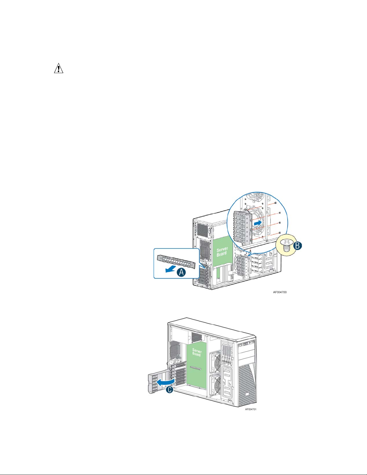
Hardware Installations and Upgrades
Installing PCI Add-in Board(s)
CAUTION
You may want to install an operating system before installing any add-in boards.
Do not overload the server board by installing add-in boards that draw excessive current.
Add-in boards can be extremely sensitive to ESD and always require careful handling. After
removing the board from its protective wrapper, place it component side up on a grounded, staticfree surface. Do not slide the board over any surface.
1. Observe the safety and ESD precautions at the beginning of this book.
2. Power down the server and unplug all peripheral devices and the AC power cable.
3. Remove the chassis cover. For instructions, see “Removing the Chassis Cover”.
4. Remove the airduct if it is installed.
5. Remove the PCI slot shield (see letter A) by pushing from the shield out from inside the chassis.
6. If the PCI card is a double width card, install the optional double width card fixture (see letter B). See
““
Installing a Double Width Card Extension Bracket” for additional information on using double
width cards. It is on page 60.
Figure 86. Removing the PCI slot shield
7. Rotate the PCI card retainer all the way up (see letter C).
Figure 87. Rotate the PCI card retainer
8. From within the chassis, press open the back panel PCI add-in board retention device (see lett er D).
®
Intel
Server Chassis P4000M Service Guide 55
Page 70

Hardware Installations and Upgrades
Figure 88. Open the back panel PCI add-in board retention device
9. Remove the PCI add-in board from its protective wrapper. Be careful not to touch the components or
gold edge connectors. Place the add-in board on an anti-static surface. Record the type and serial
number of the add-in board in your equipment log. Set the jumpers or switches on the board
according to the manufacturer’s instructions.
10. While holding the PCI add-in board by its top edge or upper corners, firmly press the add-in board
into an expansion slot on the server board. If using double width card, align the card edge to the
guiding slot on the double width card fixture.See ““
Bracket”
” for additional information on using double width cards. It is on page 60.
Installing a Double Width Card Extension
Figure 89. Installing PCI Add-in Board
56 Intel
®
Server Chassis P4000M Service Guide
Page 71

11. Close the PCI card retention device as shown below .
Figure 90. Closing the PCI Card Retention Device
Hardware Installations and Upgrades
12. Close the PCI card retainer as shown below. Use screws to better secure the PCI-e cards.
Figure 91. Closing the PCI Card Retainer
13. Attach cables if necessary.
14. Install the air duct if it is removed. For instructions, see “Installing the Airduct”.
15. Install the chassis cover. For instructions, see “Installing the Chassis Cover”.
16. Plug all peripheral devices and the AC power cable into the server.
17. Power up the server.
®
Intel
Server Chassis P4000M Service Guide 57
Page 72

Hardware Installations and Upgrades
Installing a Double Width Card Extension Bracket
A GPGPU card bracket can help better secure a heavy double width card, the bracket can be installed on
position as shown in the figure below.
Figure 92. Installing the Double Width Card Fixture
Users need to install the double width card extension bracket to make a non-full length double width card
to be full length, in order to take advantage of the double width card bracket.
Figure 93. Installing the double width card extension bracket
58 Intel
®
Server Chassis P4000M Service Guide
Page 73

Hardware Installations and Upgrades
Figure 94. Secure the Double Width card with Double Width Card bracket
The following figures show an example of the GPGPU bracket.
Figure 95. Side View of a Double Width Card Extender Example
Figure 96. Top View of a Double Width Card Extender Example
Removing and Installing the Fixed Power Supply
WARNING
Hazardous voltage, current, and energy levels are present inside the power supply. There are no
user-serviceable parts inside it; servicing should be done by technically qualified personnel.
Removing the Fixe d Power Supply
1. Observe the safety and ESD precautions at the beginning of this book.
2. Power down the server and unplug all peripheral devices and the AC power cable.
3. Remove the chassis cover. For instructions, see “Removing the Chassis Cover”.
4. Remove the air duct if it is installed. For instructions, see “Installing the Airduct”.
5. Disconnect all internal power cables from chassis components and server board.
6. Rotate the power supply locking device counter-clockwise (see letter A) and remove the fixed power
supply (see letter B).
®
Intel
Server Chassis P4000M Service Guide 59
Page 74

Hardware Installations and Upgrades
Figure 97. Removing Fixed Power Supply
Installing the Fixe d Power Supply
1. Insert new fixed power supply and rotate the power supply locking device clockwi s e (see letter A and
B).
Figure 98. Installing Fixed Power Supply
2. Reconnect power cables to other chassis components as appropriate.
3. Install the air duct. For instructions, see “Installing the Airduct”.
4. Install the chassis cover. For instructions, see “Installing the Chassis Cover”.
5. Plug all peripheral devices and the AC power cable into the server.
6. Power up the server.
60 Intel
®
Server Chassis P4000M Service Guide
Page 75

Hardware Installations and Upgrades
Installing an Additional Hotswap Power Supply Module
NOTE
/
This install procedure only applies to a chassis with redundant power supply capability.
WARNING
Hazardous voltage, current, and energy levels are present inside the power supply. There are no
user-serviceable parts inside it; servicing should be done by technically qualified personnel.
1. Observe the safety and ESD precautions at the beginning of this book.
2. Insert finger into finger hole in middle of filler panel and remove the filler panel from chassis.
Figure 99. Removing Power Supply F iller Panel
3. Insert the power supply module into the power supply cage and push all the way until it clicks into
place.
Figure 100. Installing Additional Hotswap Power Supply Module
®
Intel
Server Chassis P4000M Service Guide 61
Page 76

Hardware Installations and Upgrades
Replacing a Hot Swap Power Supply Module
WARNING
Hazardous voltage, current, and energy levels are present inside the power supply. There are no
user-serviceable parts inside it; servicing should be done by technically qualified personnel.
1. Observe the safety and ESD precautions at the beginning of this book.
2. Remove power cable from defective power supply.
3. Press up on green latch in the direction shown while pulling on handle to remove hot swap power supply
from chassis.
Figure 101. Removing Hotswap Power Supply Module from Chassis
4. Insert new power supply module into the power supply cage and push all the way until it clicks into place.
Figure 102. Installing Hotswap Power Supply Module into Chassis
62 Intel
®
Server Chassis P4000M Service Guide
Page 77

Hardware Installations and Upgrades
Replacing the Power Distribution Board for 460W/750W PSUs
WARNING
Hazardous voltage, current, and energy levels are present inside the power supply. There are no
user-serviceable parts inside it; servicing should be done by technically qualified personnel.
1. Observe the safety and ESD precautions at the beginning of this book.
2. Power down the server and unplug all peripheral devices and the AC power cable.
3. Remove the chassis cover. For instructions, see “Removing the Chassis Cover”.
4. Remove the air duct. For instructions, see “Installing the Airduct ”.
5. Disconnect all internal power cables from chassis components and server board.
6. If present, press on green lat c h in the direction shown while pulling on handle to remove power
supply from chassis. Repeat this step for the second hotswap power supply if it is installed.
Figure 103. Removing Hotswap Power Supply Module from Chassis
7. Loosen screws securi ng the bracket with power distribution board to the chassis (see letter A and B).
Figure 104. Loosening the Bracket with Power Distribution Board from Chassis
®
Intel
Server Chassis P4000M Service Guide 63
Page 78

Hardware Installations and Upgrades
8. Push the bracket forward to release the latch which secure the bracket then pull out the bracket from
the chassis (see letter C).
Figure 105. Removing the Bracket with Power Distribution Board from Chassis
9. Loosen screws securi ng the power distribution board to the bracket, and then remove it from the
bracket (see letter D).
Figure 106. Removing the Power Distribution B oard from Bracket
64 Intel
®
Server Chassis P4000M Service Guide
Page 79

Hardware Installations and Upgrades
10. Slide the new power distribution board to the bracket (see letter E) and secure the new power
distribution board to the bracket using the same screws (see letter F).
Figure 107. Sliding the New Power Distribution Board in Bracket
Figure 108. Securing the New Power Distribution Board in Bracket
®
Intel
Server Chassis P4000M Service Guide 65
Page 80

Hardware Installations and Upgrades
11. Slide the bracket with the new power distribution board all the way into the power supply cage (see
letter G).
Figure 109. Sliding the Bracket into Power Supply Cage
12. Then pull back until the latch on the bracket is engaged with the power supply cage and make sure
the screw holes on the bracket is aligned with the screw holes on power supply cage (see lett er “H”).
And then secure the bracket with the screws (see letter “I” and “J”).
Figure 110. Securing the Bracket into Power Supply Cage
66 Intel
®
Server Chassis P4000M Service Guide
Page 81

Hardware Installations and Upgrades
13. Reconnect the power cables as appropriate.
14. Insert the power supply(s) into the power supply cage and push all the way until it clicks into place.
Figure 111. Installing Hotswap Power Supply Module into Chassis
15. Reinstall the air duct. For instructions, see “Installing the Airdu ct”.
16. Re-install the chassis cover. For instructio ns, se e “Installing the Chassis Cover’.
17. Plug all peripheral devices and the AC power cable into the server.
18. Power up the server.
®
Intel
Server Chassis P4000M Service Guide 67
Page 82

Hardware Installations and Upgrades
Replacing the Power Distribution Board for 1200-W PSUs
WARNING
Hazardous voltage, current, and energy levels are present inside the power supply. There are no
user-serviceable parts inside it; servicing should be done by technically qualified personnel.
1. Follow instructions in “Replacing the Power Distribution Board for 460-W/750-W PSUs” except
the Power Distribution Board is located at different place in the PDB bracket.
2. To remove the Power Distribution Board, loosen screws securing the PDB bracket to the
chassis. See letter A. Push the bracket forward to release the latch which secure the bracket
then pull out the bracket from the chassis. See letter B. The figure shows the different PDB
locations for 460-W/750-W PSU and 1200-W PSU.
Figure 112. Removing the PDB for 1200-W PSU
68 Intel
®
Server Chassis P4000M Service Guide
Page 83

Hardware Installations and Upgrades
3. To install the Power Distribution Board, slide the bracket with the new PDB all the way into the
power supply cage until the latch on the bracket is engaged with the power supply cage and
make sure the screw holes on the bracket is aligned with the screw holes on power supply cage.
See letter A. Then secure the bracket with the screws. See letter B. The figure shows the
different PDB locations for 460-W/750-W PSU and 1200-W PSU.
Figure 113. Installing the PDB for 1200-W PSU
®
Intel
Server Chassis P4000M Service Guide 69
Page 84

Hardware Installations and Upgrades
Removing and Installing the Top Cosmetic Cover
Removing the Top Cosmetic Cover
1. Observe the safety and ESD precautions at the beginning of this book.
2. Power down the server and unplug all peripheral devices and the AC power cable.
3. Remove the chassis cover. For instructions, see “Removing the Chassis Cover”.
4. Press the latches under the top cosmetic cover to release the cosmetic cover (see letter A) and
remove the top cosmetic cover (see letter B).
Figure 114. Removing the Top Cosmetic Cover
Installing the Top Cosmetic Cover
1. Observe the safety and ESD precautions at the beginning of this book.
2. Power down the server and unplug all peripheral devices and the AC power cable.
3. Attach the top cosmetic cover to the chassis and make sure the edges of the top cosmetic cover fit
the sides of the chassis top. Then slide the top cosmetic cover forward until the latches on the top
cosmetic cover are engaged with the chassis.
Figure 115. Installing the Top Cosmetic Cover
70 Intel
®
Server Chassis P4000M Service Guide
Page 85

Hardware Installations and Upgrades
Removing and Installing the Chassis Feet
Removing the Chassis Feet
1. Observe the safety and ESD precautions at the beginning of this book.
2. Power down the server and unplug all peripheral devices and the AC power cable.
3. Lay the chassis down on its right side.
4. Loose the screws securing the rubber foot to the chassis and then remove the rubber foot from chassis.
Figure 116. Removing the Chassis Feet
5. Repeat above steps until all four feet are removed.
Installing the Chassis Feet (Pedest al Configuration Only)
NOTE
/
Do not install feet on your Intel® Server Chassis P4000M family if it is to be installed in a rack.
Only install feet on a pedestal-configured chassis.
1. Observe the safety and ESD precautions at the beginning of this book.
2. Power down the server and unplug all peripheral devices and the AC power cable.
3. Lay the chassis down on its right side.
4. Insert rubber foot into chassis hole (s ee letter A).
5. Secure foot by inserting screw through the rubber foot (see letter B).
6. Repeat above steps until all four feet are installed.
®
Intel
Server Chassis P4000M Service Guide 71
Page 86

Hardware Installations and Upgrades
Figure 117. Installing the Chassis Feet
7. Put chassis in the upright pos it ion.
8. Reconnect all peripheral devices and the AC power cable to the server. Power up the server.
Removing and Installing the Front Panel Tray
CAUTION
The front panel is NOT hot swappable. Before removing or replacing the control panel, you must
first take the server out of service, turn off all peripheral devices connected to the system, turn off
the system by pressing the power button, and unplug the AC power cord from the system or wall
outlet.
Removing the Front Control Panel Tray
1. Observe the safety and ESD precautions at the beginning of this book.
2. Power down the server and unplug all peripheral devices and the AC power cable.
3. Remove the chassis cover. For instructions, see “Removing the Chassis Cover”.
4. Remove the front bezel if it is installed. For instructions, see “Removing the Front Bezel”.
5. Remove the air duct if it is installed.
6. Disconnect the front panel cable, USB cable from the server board.
72 Intel
®
Server Chassis P4000M Service Guide
Page 87

Hardware Installations and Upgrades
Figure 118. Disconnecting the Cables from the Server Board
7. Loose the front panel cable and USB cable from the wire clip on chassis.
8. Press the latch at the sides of t he front panel (see Letter A) and carefully slide the front panel out
(see Letter B).
CAUTION
Do not slide the front panel out far from the front of the chassis before you disconnect
the instruction cable from the front panel board.
Figure 119. Sliding the Front Panel Tray out from the Chassis
®
Intel
Server Chassis P4000M Service Guide 73
Page 88

Hardware Installations and Upgrades
9. Slide the front panel out from the front of the chassis to the place (see Letter C) so that you can reach
the front panel cable and intrusion cable connectors at the rear of the front panel. Then disconnect
the front panel cable and intrusion switch cable from the front panel board (see Letter D).
Figure 120. Disconnecting the Cables from Front Panel Board
10. Slide the front panel tray out.
Installing the Front Panel Tray
1. Observe the safety and ESD precautions at the beginning of this book.
2. Power down the server and unplug all peripheral devices and the AC power cable.
3. Remove the chassis cover. For instructions, see “Removing the Chassis Cover”.
4. Remove the front bezel if it is installed. For instructions, see “Removing the Front Bezel”.
5. Remove the air duct if it is installed.
6. Attach the front panel cab le an d the chass is intru si on cabl e (see Letter A) to the front panel board.
Figure 121. Connecting the Cables to the Front Panel Board
74 Intel
®
Server Chassis P4000M Service Guide
Page 89

7. Slide the front panel tray in chassis
Figure 122. Installing the Front Panel Tray in Chassis
Hardware Installations and Upgrades
8. Connect the front panel and USB cables to server board.
Figure 123. Connecting the Cables to Server Boar d the Front Panel Tray in Chassis
9. Install the front bezel. For instructions, see “Removing and Installing the Front Bezel”.
10. Install the air duct based on board requirement.
11. Install the chassis cover. For instructions, see “Installing the Chassis Cover”.
12. Plug all peripheral devices and the AC power cable into the server.
13. Power up the server.
®
Intel
Server Chassis P4000M Service Guide 75
Page 90

Hardware Installations and Upgrades
Replacing the Front Panel Board
1. Observe the safety and ESD precautions at the beginning of this book.
2. Power down the server and unplug all peripheral devices and the AC power cable.
3. Remove the chassis cover. For instructions, see “Removing the Chassis Cover”.
4. Remove the front bezel if it is installed. For instructions, see “Removing the Front Bez el”.
5. Remove the front panel tray if it is installed. For instructions, see “Removing the Front Panel Tra y”.
6. Loose the screw (see Letter A) securing the front panel board and remove the front panel board (see
Letter B)
Figure 124. Removing the Front Panel Board
7. Remove the cap on the front panel board power button and i nsta ll the new cap on the new front panel
board power button.
Figure 125. Removing and Installing the Cap on Front P anel Board
8. Attach the new front panel board in the front panel tray (see letter A) and secure the new front panel
board with the screw (see letter B).
Figure 126. Installing the New Front Panel Board
76 Intel
®
Server Chassis P4000M Service Guide
Page 91

9. Installing the front panel tray with the front panel board. For instructions, see “Installing the Front
Panel Tray”.
10. Install the front bezel. For instructions, see “Removing and Installing the Front Bezel”.
11. Install the air duct based on board requirement.
14. Install the chassis cover. For instructions, see “Installing the Chassis Cover”.
15. Plug all peripheral devices and the AC power cable into the server.
16. Power up the server.
Installing Alternate Serial Port
1. Observe the safety and ESD precautions at the beginning of this book.
2. Power down the server and unplug all peripheral devices and the AC power cable.
3. Remove the chassis cover. For instructions, see “Removing the Chassis Cover”.
4. Remove the alternate serial port knockout by pressing the knockout from inside the chassis.
Hardware Installations and Upgrades
Figure 127. Removing the Alternate Serial Port Knockout
5. Install the serial port on the rear panel of the chassis. Connect the cable to the Serial B Connector on
your motherboard.
Figure 128. Installing the Alternate Serial Port Knockout
®
Intel
Server Chassis P4000M Service Guide 77
Page 92

Hardware Installations and Upgrades
Installing and/or Removing a Expander card
Installing the Expander card
1. Observe the safety and ESD precautions at the beginning of this book.
2. Power down the server and unplug all peripheral devices and the AC power cable.
3. Remove the chassis cover. For instructions, “Removing the Chassis Cover”.
4. Remove the fans. For instructions, see “Removing the Fixed Fan” or “Removing the Hotswap Fans”.
5. Remove the Fixed HDDs or Hotswap drive cages. For instructions, see “Remove Fixed Hard Drives”,
or “Remove 8x3.5 Hotswap Drive Cage Assemble”, or “Remove 8x2.5 Hotswap Drive Cage
Assemble”.
6. Locate the expander card bracket in the chassis. Mount the expander card to the bracket with screws.
Figure 129. Installing the Expander Card
7. Connect the data cable between server board and expander card, and between expander and
backplane(s). See documents for your server boards for instructions.
8. Install the Fixed HDDs or Hotswap drive cages. For instructions, see “Install Fixed Hard Drives”, or
“Install 8x3.5 Hotswap Drive Cage Assemble”, or “Install 8x2.5 Hotswap Drive Cage Assemble”.
9. Install the fans. For instructions, see “Install the Fixed Fan” or “Install the Hotswap Fans”.
10. Install the chassis cover. For instructions, “Install the Chassis Cover”.
Removing the Expander card
1. Observe the safety and ESD precautions at the beginning of this book.
2. Power down the server and unplug all peripheral devices and the AC power cable.
3. Remove the chassis cover. For instructions, “Removing the Chassis Cover”.
4. Remove the fans. For instructions, see “Removing the Fixed Fan” or “Removing the Hotswap Fans”.
5. Remove the Fixed HDDs or Hotswap drive cages. For instructions, see “Remove Fixed Hard Drives”,
or “Remove 8x3.5 Hotswap Drive Cage Assemble”, or “Remove 8x2.5 Hotswap Drive Cage
Assemble”.
78 Intel
®
Server Chassis P4000M Service Guide
Page 93

Hardware Installations and Upgrades
6. Unplug all the cables connected to the expander card.
7. Remove the expander card from expander card bracket by releasing the securing screws.
Figure 130. Removing the Expander card
8. Install the Fixed HDDs or Hotswap drive cages. For instructions, see “Install Fixed Hard Drives”, or
“Install 8x3.5 Hotswap Drive Cage Assemble”, or “Install 8x2.5 Hotswap Drive Cage Assemble”.
9. Install the fans. For instructions, see “Install the Fixed Fan” or “Install the Hotswap Fans”.
10. Install the chassis cover. For instructions, see “Install the Chassis Cover”.
Installing and/o r Rem oving a Server/Workstation Board
NOTE
/
The server/workstation board you can install in your chassis depends upon the chassis model.
To install or remove a server board, do the following:
1. Observe the safety and ESD precautions at the beginning of this book.
2. Power down the server and unplug all peripheral devices and the AC power cable.
3. Remove the chassis cover. For instructions, see “Removing the Chassis Cover”.
4. Remove the front bezel assembly if it is installed. For instructions, see “Removing the Bezel
Assembly (Pedestal Only)”
5. Remove any PCI add-in boards that are present. For instructions, see “Rem ov ing PCI Add-in
Board(s)”.
6. If installing a server board, refer to the Service Guide and/or Quick Start User’s Guide that shipped
with your Intel
bumpers and standoffs (if necessary) that came with your chassis to secure the server/workstation
board to the chassis. Mak e sure the server/workstation board is properly seated and then tighten the
®
server/workstation board for installation instructions. Use the mounting screws,
®
Intel
Server Chassis P4000M Service Guide 79
Page 94

Hardware Installations and Upgrades
screws firmly, starting with the screws at the center of the server/workstation board. Make cable
connections per instructions in the Intel
User’s Guide.
7. If removing a server board, disconnect all cables connected to the server board.
8. Remove the mounting screws, starting with the screws at the center of the server/workstation board.
Remove the server board.
9. If desired, install any P CI Add-in boards. For instructions, see “Installing PCI Add-in Board(s)”
10. Re-install the front bezel assembly. For instructions, see “Installing the Front Bezel (Pedestal Only)”.
11. Re-install the chassis cover. For instructions, see “Installing the Chassis Cover”.
12. Plug all peripheral devices and the AC power cable into the server.
13. Power up the server.
®
server/workstation board Service Guide and/or Quick Start
Connecting and Disconnecting Cables to or from Server Workstation Board
CAUTION
Use caution when routing cables to ensure that cables do not obstruct fan airflow.
1. See your Intel® Server/Workstation Board Service Guide or Quick Start User’s Guide for cable
connection locations.
2. If your server has a hot swap power supply, secure the cables (that route toward the
server/workstation board) to the chassis.
Connecting Cable s to Server/Workstation Board
1. If your server has a hot swap power supply, connect the cables (that route toward the
server/workstation board) to the chassis.
®
2. See your Intel
connection locations.
Server/Workstation Board Service Guide or Quick Start User’s Guide for c able
Removing Cables from Server/Workstation Board
1. If your server has a hot swap power supply, remove the cables (that route toward the
server/workstation board) to the chassis.
®
2. See your Intel
connection locations.
Server/Workstation Board Service Guide or Quick Start User’s Guide for c able
Rack-mounted Systems
Your Intel® Server Chassis P4000M family can be mounted into a rack. Intel® provides a tool-less
rail kit and a cable management arm to mount this server chassis into a rack. When installing the
chassis into a rack, Intel
In other words, install the first system in the rack into the bottom position of the rack, the second
system in the second position from the bottom, and so on.
®
recommends you install systems from the bottom of the rack to the top.
80 Intel
®
Server Chassis P4000M Service Guide
Page 95

Hardware Installations and Upgrades
Intel® Remote Management Module 4
The Intel® Remote Management Module 4 plugs into a dedicated connector on the server board
and provides additional server management functionality to the server board.
This module provides a dedicated web server for viewing server information and remote control of
the system. It also provides Remote KVM Redirection and USB Media Redirection allowing USB
devices attached to the remote system to be used on the managed server.
®
Intel
Server Chassis P4000M family provide two Intel® Remote Management Module 4
knockout. For instructions on installing the Intel
Remote Management Module 4 User Guide.
®
Remote Management Module 4, see Intel®
Figure 131. RMM4 knockout
®
Intel
Server Chassis P4000M Service Guide 81
Page 96

Hardware Installations and Upgrades
Mechanical Locks
All configurations of the server chassis can support the installation of a padlock loop (see letter
A in the following figure) at the rear of the chassis.
Figure 132. Mechanical Locks
82 Intel
®
Server Chassis P4000M Service Guide
Page 97

Technical Reference
Parameter
Tolerance
MIN
NOM
MAX
UNITS
+12V
- 5%/+5%
+11.40
+12.00
+12.60
V
+12V stby
- 5%/+5%
+11.40
+12.00
+12.60
V
3 Technical Reference
Power Supply Specification
The power supply specifications for your Intel® Server Chassis P4000M family depend upon the
configuration of chassis you purchased. Below power supply configurations are av ailable:
460-W hotswap power supply
550-W fixed power supply
750-W hotswap power supply
1200-W hotswap power supply
460-W Hotswap Power Supply Input Voltage
100-127V at 50/60 Hz; 10A max.
200-240V at 50/60 Hz; 10A max.
460-W Hotswap Power Supply Output Voltages
The following table defines the minimum power and current ratings. The power supply must meet
both static and dynamic voltage regulation requirements for all conditions.
Table 3. 460-W Power Supply Output Voltages
rms
rms
550-W Single Power Supply Input Voltage
100-127V at 50/60 Hz; 10A max.
200-240V at 50/60 Hz; 10A max.
550-W Single Power Supply Output Voltages
The following table defines the minimum power and current ratings. The power supply must meet
both static and dynamic voltage regulation requirements for all conditions.
®
Intel
Server Chassis P4000M Service Guide 83
Page 98

Technical Reference
+12V
- 5%/+5%
+11.40
+12.00
+12.60
V
+12V stby
- 5%/+5%
+11.40
+12.00
+12.60
V
+12V
- 5%/+5%
+11.40
+12.00
+12.60
V
+12V stby
- 5%/+5%
+11.40
+12.00
+12.60
V
Table 4. 550-W Power Supply Output Voltages
Parameter Min. Max. Peak Unit
3.3V 0.5 18.0 A
5V 0.3 15.0 A
12V1 0.7 24.0 28.0 A
12V2 0.7 24.0 28.0 A
12V3 1.5 18.0 A
− 12V 0.0 0.5 A
5Vstby
0.0 3.0 3.5 A
Notes:
1. Maximum combined power for all output shall not exceed 550W.
2. Peak combined power for all outputs shall not exceed 630W for 20 seconds.
3. Maximum combined power of 12V1, 12V2 and 12V3 shall not exceed 530W.
750-W Hotswap Power Supply Input Voltage
100-127V at 50/60 Hz; 10A max.
200-240V at 50/60 Hz; 10A max.
750-W Hotswap Power Supply Output Voltages
Table 5. 750-W Power Supply Output Voltages
Parameter Tolerance Min Nom Max Units
1200-W Hotswap Power Supply Input Voltage
100-127V at 50/60 Hz; 10A max.
200-240V at 50/60 Hz; 10A max.
rms
rms
1200-W Hotswap Power Supply Output Voltages
Table 6. 1200-W Power Supply Output Voltages
Parameter Tolerance MIN NOM MAX UNITS
®
84 Intel
Server Chassis P4000M Service Guide
rms
rms
Page 99

Operating temperature
+10°C to +35°C with the maximum rate of change not to exceed 10°C per hour.
Non-operating temperature
-40°C to +70°C
Non-operating humidity
Acoustic noise
7.0 BA LWA in a typical office ambient temperature (18-25°C)
Shock Operating
Half sine, 2 g, 11 milliseconds
Shock Unpackaged
Trapezoidal, 25g, velocity change 136 inches/second (40 lbs to < 80 lbs)
Shock Packaged
Operational after a free fall of 9 – 36 inches depending on the weight
Vibration unpackaged
5 Hz to 500 Hz 2.20 g RMS random
Vibration packaged
5 Hz to 500 Hz 1.09 g RMS random
Packaged shock
Operational after a free fall of 9 – 36-inches depending on the weight
ESD
Air discharge: 0 to 15.0kV; Contact Discharge: 0 to 8.0kV
System Environmental Requirements
Table 7. Environmental Requirements
Parameter Limits
50% to 90%, non-condensing with a maximum wet bulb of 28°C (at temperatures
from 25°C to 35°C)
Technical Reference
Current Usage
Calculation Power Usage
The total combined wattage for your configuration must be less than the wattage rating for your
power supply. Use the two worksheets in this section to calculate the total used by your
configuration. For current and voltage requirements of add-in boards and peripherals, see your vendor
documents.
Worksheet, Calculating DC Power Usage
Table 8. Power Usage Worksheet
Current (maximum) at voltage level
Device
Baseboard, Front Panel
Board and Fans
Processor(s)
Memory
3.5-inch Diskette Drive
CD-ROM Drive
+3.3V + 5V -5 V +12 V -12 V 5V Standby
Second 5.25-inch Device
®
Intel
Server Chassis P4000M Service Guide 85
Page 100

Technical Reference
(V X A = W)
Current (maximum) at voltage level
Third 5.25-inch Device
1st Hard Drive
2nd Hard Drive
3rd Hard Drive
4th Hard Drive
Expansion Board 1
Expansion Board 2
Expansion Board 3
Expansion Board 4
Expansion Board 5
Expansion Board 6
Intel® Remote Management
Module
Control Panel
Total Current
Worksheet, Total Combined Power Used by the Server
From the previous worksheet, enter the total current for each column.
Multiply the voltage by the total current to get the total wattage for each voltage level.
Add the total wattage for each voltage level to arrive at the total combined power usage for the power
subsystem.
Table 9. Power Usage Worksheet 2
Voltage level and total current
(+3.3 V) X (______ A)
(+5 V) X (______ A)
(+12 V) X (______ A)
(–12 V) X (______ A)
(5 V standby) X (______ A)
Total Combined Wattage
________ W
________ W
________W
________ W
________ W
________ W
Total watts for each voltage level
86 Intel
®
Server Chassis P4000M Service Guide
 Loading...