

Intel S2600CP Family, P4000CP Family, S2600CP Series, P4000CP Series Technical Product Specification
Page 1
Intel® Server Board S2600CP Family
Intel
®
Server System P4000CP Family
Technical Product Specification
Intel order number G26942-003
Revision 1.1
March, 2012
Enterprise Platforms and Services Division - Marketing
Page 2

Table of Contents Intel® Server Board S2600CP and Server System P4000CP TPS
Revision History
Date Revision
Number
January, 2012 1.0 Initial release.
March, 2012 1.1 Added Intel® Server Board S2600CP2J.
Modifications
Disclaimers
Information in this document is provided in connection with Intel® products. No license, express or implied, by
estoppel or otherwise, to any intellectual property rights is granted by this document. Except as provided in Intel's
Terms and Conditions of Sale for such products, Intel assumes no liability whatsoever, and Intel disclaims any
express or implied warranty, relating to sale and/or use of Intel products including liability or warranties relating to
fitness for a particular purpose, merchantability, or infringement of any patent, copyright or other intellectual property
right. Intel products are not intended for use in medical, lifesaving, or life sustaining applications. Intel may make
changes to specifications and product descriptions at any time, without notice.
Designers must not rely on the absence or characteristics of any features or instructions marked "reserved" or
"undefined." Intel reserves these for future definition and shall have no responsibility whatsoever for conflicts or
incompatibilities arising from future changes to them.
This document contains information on products in the design phase of development. Do not finalize a design with
this information. Revised information will be published when the product is available. Verify with your local sales office
that you have the latest datasheet before finalizing a design.
The Intel
errors known as errata which may cause the product to deviate from published specifications. Current characterized
errata are available on request.
This document and the software described in it is furnished under license and may only be used or copied in
accordance with the terms of the license. The information in this manual is furnished for informational use only, is
subject to change without notice, and should not be construed as a commitment by Intel Corporation. Intel
Corporation assumes no responsibility or liability for any errors or inaccuracies that may appear in this document or
any software that may be provided in association with this document.
Except as permitted by such license, no part of this document may be reproduced, stored in a retrieval system, or
transmitted in any form or by any means without the express written consent of Intel Corporation.
Intel, Pentium, Itanium, and Xeon are trademarks or registered trademarks of Intel Corporation.
*Other brands and names may be claimed as the property of others.
Copyright © 2012 Intel Corporation
ii
®
Server Board S2600CP family and Intel® Server System P4000CP family may contain design defects or
Revision 1.1
Intel order number G26942-003
Page 3

Intel® Server Board S2600CP and Server System P4000CP TPS Table of Contents
Table of Contents
1. Introduction ............................................................................................................................ 1
1.1 Server Board Use Disclaimer .................................................................................... 1
®
2. Intel
2.1 Intel
2.2 Server Board Layout ................................................................................................. 5
3. Intel
3.1 Integrated System Family Overview ....................................................................... 20
3.2 Intel
4. Intel
4.1 Processor Support ................................................................................................... 27
4.2 Processor Functions Overview ............................................................................... 31
4.3 Intel
Server Board S2600CP Overview .............................................................................. 3
®
Server Board S2600CP Feature Set ............................................................... 3
2.2.1 Server Board Connector and Component Layout .................................................... 7
2.2.2 Server Board Mechanical Drawings ....................................................................... 10
2.2.3 Server Board Rear I/O Layout ................................................................................ 18
®
Server System P4000CP Overview .......................................................................... 20
®
Server System P4000CP Family View .......................................................... 22
3.2.1 Intel
3.2.2 Intel
3.2.3 Intel
®
Server Board S2600CP Functional Architecture .................................................... 25
®
Server System P4308CP4MHEN View ......................................................... 22
®
Server System P4308CP4MHGC View ........................................................ 23
®
Server System P4208CP4MHGC View ........................................................ 24
4.1.1 Processor Socket Assembly ................................................................................... 27
4.1.2 Processor Population Rules .................................................................................... 27
4.2.1 Intel
®
QuickPath Interconnect ................................................................................. 31
4.2.2 Integrated Memory Controller (IMC) and Memory Subsystem .............................. 32
4.2.3 Processor Integrated I/O Module (IIO) .................................................................... 38
®
C600 Chipset Functional Overview ............................................................... 38
4.3.1 Digital Media Interface (DMI) .................................................................................. 40
4.3.2 PCI Express* Interface ............................................................................................ 40
4.3.3 Serial ATA (SATA) Controller ................................................................................. 40
4.3.4 Serial Attached SCSI (SAS)/SATA Controller ........................................................ 41
4.3.5 AHCI ........................................................................................................................ 41
4.3.6 PCI Interface............................................................................................................ 41
4.3.7 Low Pin Count (LPC) Interface ............................................................................... 41
4.3.8 Serial Peripheral Interface (SPI) ............................................................................. 41
4.3.9 Compatibility Modules (DMA Controller, Timer/Counters, Interrupt Controller) ..... 41
4.3.10 Advanced Programmable Interrupt Controller (APIC) ............................................ 42
4.3.11 Universal Serial Bus (USB) Controllers .................................................................. 42
4.3.12 Gigabit Ethernet Controller ..................................................................................... 42
4.3.13 RTC ......................................................................................................................... 42
4.3.14 GPIO ........................................................................................................................ 42
Revision 1.1
Intel order number G26942-003
iii
Page 4

Table of Contents Intel® Server Board S2600CP and Server System P4000CP TPS
4.3.15 Enhanced Power Management ............................................................................... 42
4.3.16 Manageability .......................................................................................................... 43
4.3.17 System Management Bus (SMBus 2.0) .................................................................. 43
4.3.18 Virtualization Technology for Directed I/O (Intel
®
VT-d) ......................................... 43
4.3.19 KVM/Serial Over LAN (SOL) Function .................................................................... 43
4.3.20 On-board SAS/SATA Support and Options ............................................................ 43
4.4 PCI Subsystem ........................................................................................................ 45
4.5 Integrated Baseboard Management Controller Overview ...................................... 46
4.5.1 Super I/O Controller ................................................................................................ 47
4.5.2 Graphics Controller and Video Support .................................................................. 48
4.5.3 Baseboard Management Controller ........................................................................ 49
4.6 Network Interface .................................................................................................... 50
5. System Security ................................................................................................................... 51
5.1 BIOS Password Protection ..................................................................................... 51
5.2 Trusted Platform Module (TPM) Support ................................................................ 52
5.2.1 TPM security BIOS .................................................................................................. 52
5.2.2 Physical Presence ................................................................................................... 53
5.2.3 TPM Security Setup Options ................................................................................... 53
5.3 Intel
6. Intel
®
Server Board S2600CP and Intel® Server System P4000CP Platform
®
Trusted Execution Technology ...................................................................... 55
Management ................................................................................................................................ 57
6.1 Server Management Function Architecture ............................................................ 57
6.1.1 Feature Support ...................................................................................................... 57
6.1.2 Basic and Advanced Features ................................................................................ 59
6.1.3 Integrated BMC Hardware: Emulex* Pilot III .......................................................... 60
6.2 Server Management Functional Specifications ...................................................... 62
6.2.1 BMC Internal Timestamp Clock .............................................................................. 62
6.2.2 System Event Log (SEL) ......................................................................................... 63
6.2.3 Field Replaceable Unit (FRU) Inventory Device ..................................................... 63
6.2.4 BMC Beep Codes .................................................................................................... 63
6.2.5 Diagnostic Interrupt (NMI) Button ........................................................................... 64
6.2.6 BMC Watchdog ....................................................................................................... 64
6.3 Sensor Monitoring ................................................................................................... 65
6.3.1 Overview .................................................................................................................. 65
6.3.2 Core Sensors .......................................................................................................... 65
6.3.3 BMC System Management Health Monitoring ....................................................... 67
6.3.4 Processor Sensors .................................................................................................. 67
6.3.5 Thermal and Acoustic Management ....................................................................... 67
6.3.6 Thermal Sensor Input to Fan Speed Control .......................................................... 68
6.3.7 Power Supply Status\Health Sensors ..................................................................... 68
6.3.8 System Event Sensor .............................................................................................. 70
iv
Intel order number G26942-003
Revision 1.1
Page 5

Intel® Server Board S2600CP and Server System P4000CP TPS Table of Contents
6.4 Channel Management ............................................................................................. 70
6.4.1 Channel Management ............................................................................................. 70
6.4.2 User Model .............................................................................................................. 71
6.4.3 LAN Interface .......................................................................................................... 71
6.5 Advanced Management Feature Support ............................................................... 81
6.5.1 Enabling Advanced Management Features ........................................................... 81
6.5.2 Keyboard, Video, Mouse (KVM) Redirection .......................................................... 82
6.5.3 Media Redirection ................................................................................................... 83
6.6 Intel
®
Intelligent Power Node Manager (NM) .......................................................... 84
6.6.1 Hardware Requirements ......................................................................................... 84
6.6.2 Features .................................................................................................................. 84
6.6.3 ME Firmware Update .............................................................................................. 84
6.6.4 SmaRT/CLST .......................................................................................................... 85
6.7 EU Lot 6 Mode ........................................................................................................ 85
6.7.1 Impact to System Features ..................................................................................... 86
7. Intel
®
Server Board S2600CP Connector/Header Locations and Pin-outs ................... 87
7.1 Power Connectors ................................................................................................... 87
7.1.1 Main Power Connector ............................................................................................ 87
7.1.2 CPU Power Connectors .......................................................................................... 87
7.2 Front Panel Header and Connectors ...................................................................... 87
7.2.1 Front Panel Header ................................................................................................. 88
7.2.2 Front Panel USB Connector ................................................................................... 88
7.2.3 Local Control Panel Connector ............................................................................... 88
7.3 On Board Storage Connectors ................................................................................ 89
7.3.1 SATA Connectors: 6Gbps ....................................................................................... 89
7.3.2 SATA Connectors: 3Gbps ....................................................................................... 89
7.3.3 SATA SGPIO Connector ......................................................................................... 89
7.3.4 SAS Connectors ...................................................................................................... 90
7.3.5 SAS SGPIO Connectors ......................................................................................... 90
7.3.6 Intel
®
RAID C600 Upgrade Key Connector ............................................................ 90
7.3.7 HSBP_I2C Header .................................................................................................. 91
7.3.8 HDD LED Header .................................................................................................... 91
7.3.9 Internal Type- A USB Connector ............................................................................ 91
7.3.10 Internal eUSB SSD Header .................................................................................... 91
7.4 Management and Security Connectors .................................................................. 91
7.4.1 RMM4_Lite Connector ............................................................................................ 91
7.4.2 RMM4_NIC Connector ............................................................................................ 92
7.4.3 TPM Connector ....................................................................................................... 92
7.4.4 PMBUS Connector .................................................................................................. 92
7.4.5 Chassis Intrusion Header ........................................................................................ 93
7.4.6 IPMB Connector ...................................................................................................... 93
Revision 1.1
Intel order number G26942-003
v
Page 6

Table of Contents Intel® Server Board S2600CP and Server System P4000CP TPS
7.5 FAN Connectors ...................................................................................................... 93
7.5.1 System FAN Connectors ......................................................................................... 93
7.5.2 CPU FAN Connector ............................................................................................... 94
7.6 Serial Port and Video Connectors .......................................................................... 94
7.6.1 Serial Port A Connector (DB9) ................................................................................ 94
7.6.2 Serial Port B Connector .......................................................................................... 94
7.6.3 Video Connector ...................................................................................................... 94
8. Intel
®
Server Board S2600CP Jumper Blocks .................................................................. 96
8.1 BIOS Default (a.k.a CMOS Clear) and Password Reset Usage Procedure .......... 97
8.1.1 Set BIOS to default (a.k.a Clearing the CMOS) ..................................................... 97
8.1.2 Clearing the Password ............................................................................................ 97
8.2 Integrated BMC Force Update Procedure .............................................................. 98
8.3 ME Force Update Jumper ....................................................................................... 98
8.4 BIOS Recovery Jumper .......................................................................................... 99
9. Intel
®
Light Guided Diagnostics ....................................................................................... 100
9.1 5-volt Stand-by LED .............................................................................................. 100
9.2 Fan Fault LED’s ..................................................................................................... 100
9.3 DIMM Fault LEDs .................................................................................................. 101
9.4 System ID LED, System Status LED and POST Code Diagnostic LEDs ............ 102
9.4.1 System ID LED ...................................................................................................... 103
9.4.2 System Status LED ............................................................................................... 104
9.4.3 POST Code Diagnostic LEDs ............................................................................... 105
10. Intel
®
Server System P4000CP Front Control Panel and Back Panel .......................... 106
10.1 Front Control Panel Overview ............................................................................... 106
10.1.1 Front Control Panel LED/Button Functionality ...................................................... 106
10.1.2 Front Control Panel LED Status ............................................................................ 108
10.2 Back Panel Overview ............................................................................................ 108
11. Intel
®
Server System P4000CP Storage and Peripheral Drive Bays ............................ 110
11.1 2.5” Hard Disk Drive Support ................................................................................ 110
11.1.1 2.5” Drive Hot-Swap Backplane Overview ........................................................... 111
11.1.2 Cypress* CY8C22545 Enclosure Management Controller .................................. 112
11.2 3.5” Hard Disk Drive Support ................................................................................ 113
11.2.1 3.5” Drive Hot-Swap Backplane Overview ........................................................... 114
11.2.2 Cypress* CY8C22545 Enclosure Management Controller .................................. 116
11.3 SAS Expander Card Option RS2CV240 ............................................................... 116
11.4 Optical Drive Support ............................................................................................ 117
11.5 Low Profile eUSB SSD Support ............................................................................ 117
12. Intel
®
Server System P4000CP Thermal Management ................................................... 119
12.1 Thermal Operation and Configuration Requirements........................................... 119
12.2 Thermal Management Overview ........................................................................... 119
12.3 System Fans.......................................................................................................... 119
vi
Intel order number G26942-003
Revision 1.1
Page 7

Intel® Server Board S2600CP and Server System P4000CP TPS Table of Contents
12.3.1 Non-Redundant Cooling Solution ......................................................................... 119
12.3.2 Redundant Cooling Solution ................................................................................. 120
12.3.3 Fan Control ............................................................................................................ 121
12.3.4 Fan Header Connector Descriptions .................................................................... 121
®
13. Intel
13.1 Intel
Server System P4000CP Power System Options ................................................ 122
®
Server System P4000CP Power System Options Overview ...................... 122
13.2 550-W Power Supply ............................................................................................ 122
13.2.1 Mechanical Overview ............................................................................................ 122
13.2.2 Temperature Requirements .................................................................................. 126
13.2.3 AC Input Requirements ......................................................................................... 127
13.2.4 Efficency ................................................................................................................ 129
13.2.5 DC Output Specification ........................................................................................ 129
13.2.6 Protection Circuits ................................................................................................. 134
13.2.7 Control and Indicator Functions ............................................................................ 135
13.3 750-W Power Supply ............................................................................................ 136
13.3.1 Mechanical Overview ............................................................................................ 136
13.3.2 AC Input Requirements ......................................................................................... 139
13.3.3 Efficiency ............................................................................................................... 141
13.3.4 DC Output Specification ........................................................................................ 141
13.3.5 Protection Circuits ................................................................................................. 145
13.3.6 Control and Indicator Functions ............................................................................ 146
13.3.7 Thermal CLST ....................................................................................................... 148
13.3.8 Power Supply Diagnostic “Black Box” .................................................................. 148
13.3.9 Firmware Uploader ................................................................................................ 148
13.4 Higer Power Common Redundant Power Distribution Board (PDB) ................... 148
13.4.1 Mechanical Overview ............................................................................................ 149
13.4.1.2 DC/DC converter cooling ...................................................................................... 150
13.4.2 DC Output Specification ........................................................................................ 150
13.4.3 Protection Circuits ................................................................................................. 159
13.4.4 PWOK (Power OK) Signal .................................................................................... 160
13.4.5 PSON Signal ......................................................................................................... 160
13.4.6 PMBus ................................................................................................................... 160
14. Intel
14.1 Intel
14.2 Intel
®
Server System P4000CP Accessories ................................................................... 161
®
RAID C600 Upgrade Key ............................................................................ 161
®
Remote Management Module 4 (Intel® RMM4) .......................................... 162
14.3 Rack Options ......................................................................................................... 163
15. Design and Environmental Specifications ...................................................................... 164
15.1 Intel
15.2 Intel
®
Server Board S2600CP Design Specifications ........................................... 164
®
Server System P4000CP Environmental Limits ......................................... 164
15.3 MTBF ..................................................................................................................... 165
15.4 Server Board Power Distribution ........................................................................... 166
Revision 1.1
Intel order number G26942-003
vii
Page 8

Table of Contents Intel® Server Board S2600CP and Server System P4000CP TPS
Appendix A: Integration and Usage Tips ............................................................................... 168
Appendix B: Compatible Intel
®
Server Chassis .................................................................... 169
Appendix C: BMC Sensor Tables ........................................................................................... 170
Appendix D: Platform Specific BMC Appendix ..................................................................... 188
Appendix E: POST Code Diagnostic LED Decoder .............................................................. 193
Appendix F: POST Error Code ................................................................................................ 198
Glossary ..................................................................................................................................... 204
Reference Documents .............................................................................................................. 207
viii
Revision 1.1
Intel order number G26942-003
Page 9

Intel® Server Board S2600CP and Server System P4000CP TPS List of Figures
List of Figures
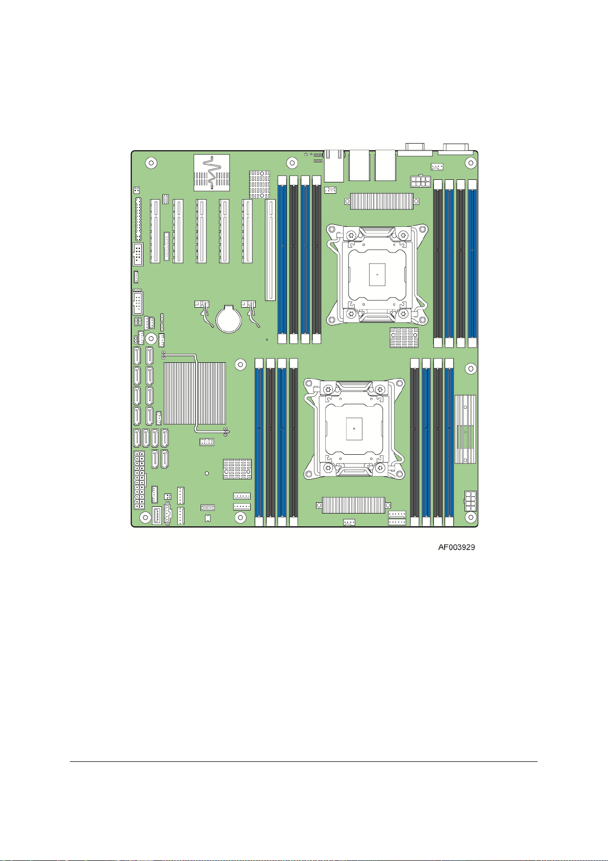
Figure 1. Intel® Server Board S2600CP4, Quad NIC ..................................................................... 5
Figure 2. Intel
Figure 3. Intel
Figure 4. Major Board Components ............................................................................................... 9
Figure 5. Mounting Hole Locations (1 of 2) .................................................................................. 10
Figure 6. Mounting Hole Locations (2 of 2) .................................................................................. 11
Figure 7. Major Connector Pin-1 Locations (1 of 3) ..................................................................... 12
Figure 8. Major Connector Pin-1 Locations (2 of 3) ..................................................................... 13
Figure 9. Major Connector Pin-1 Locations (3 of 3) ..................................................................... 14
Figure 10. Primary Side Keep-out Zone (1 of 2) .......................................................................... 15
Figure 11. Primary Side Card-Side Keep-out Zone ..................................................................... 16
Figure 12. Second Side Keep-out Zone ....................................................................................... 17
Figure 13. Rear I/O Layout of Intel
Figure 14. Rear I/O Layout of Intel
Figure 15. Intel
Figure 16. Intel
Figure 17. Intel
Figure 18. Intel
Figure 19. Intel
Figure 20. Processor Socket Assembly ....................................................................................... 27
Figure 21. Memory Subsystem for Intel
Figure 22. Intel
Figure 23. Intel
Figure 24. Intel
Figure 25. PCI Layout Diagram .................................................................................................... 46
Figure 27. Setup Utility – TPM Configuration Screen .................................................................. 54
Figure 28. Integrated BMC Hardware .......................................................................................... 62
Figure 29. High-level Fan Speed Control Process ....................................................................... 68
Figure 30. Video Connector Pin-out ............................................................................................. 95
Figure 31. Jumper Blocks (J1D3, J1D2, J1E3, J1E4, J1F1) ....................................................... 96
Figure 32. 5-volt Stand-by Status LED Location ........................................................................ 100
Figure 33. Fan Fault LED’s Location .......................................................................................... 101
Figure 34. DIMM Fault LED’s Location ...................................................................................... 102
Figure 35. Location of System Status, System ID and POST Code Diagnostic LEDs ............. 103
Figure 36. Front Control Panel LED/Button Arragement ........................................................... 106
Figure 37. Back Panel Layout with 550-W Fixed PSU............................................................... 109
Figure 38. Back Panel Layout with 750-W Redundant PSUs .................................................... 109
Figure 39. 2.5” Hard Disk Drive Cage ........................................................................................ 110
Figure 40. 2.5” Backplane, Front Side ........................................................................................ 111
®
Server Board S2600CP2, Dual NIC ...................................................................... 6
®
Server Board S2600CP2J, Dual NIC .................................................................... 7
®
Server Board S2600CP4 .................................................... 18
®
Server Board S2600CP2/S2600CP2J ................................ 19
®
Server System P4308CP4MHEN View ............................................................. 23
®
Server System P4308CP4MHGC View ............................................................ 24
®
Server System P4208CP4MHGC View ............................................................ 24
®
Server Board S2600CP2/S2600CP4 Functional Block Diagram ..................... 25
®
Server Board S2600CP2J Functional Block Diagram ...................................... 26
®
Server Board S2600CP ............................................... 32
®
Server Board S2600CP DIMM Slot Layout ....................................................... 35
®
Server Board S2600CP2/S2600CP4 Chipset Functional Block Diagram ........ 39
®
Server Board S2600CP2J Chipset Functional Block Diagram ......................... 39
Revision 1.1
Intel order number G26942-003
ix
Page 10

List of Figures Intel® Server Board S2600CP and Server System P4000CP TPS
Figure 41. 2.5” Backplane, Back Side ........................................................................................ 112
Figure 42. 3.5” Hard Disk Drive Cage ........................................................................................ 113
Figure 43. 3.5” Backplane, Front Side ........................................................................................ 114
Figure 44. 2.5” Backplane, Back Side ........................................................................................ 115
Figure 45. Internal SAS Expander Installation ........................................................................... 116
Figure 46. Internal 24-Port SAS Expander Card ........................................................................ 116
Figure 47. Optical Drive .............................................................................................................. 117
Figure 48. eUSB SSD Support ................................................................................................... 118
Figure 49. Fixed Fans in Intel
Figure 50. Hot-swap Fans in Intel
®
Server Chassis P4308XXMXXMFEN ....................................... 120
®
Server Chassis P4308XXMXXMHGC ............................... 120
Figure 51. Mechanical Drawing for 550-W Power Supply Enclosure ........................................ 123
Figure 52. Output Cable Harness for 550-W Power Supply ...................................................... 124
Figure 53. Differential Noise test setup ...................................................................................... 132
Figure 54. Output Voltage Timing............................................................................................... 133
Figure 55. Turn On/Off Timing (Power Supply Signals) ............................................................ 134
Figure 56. PSON# Required Signal Characteristic .................................................................... 136
Figure 57. 750-W Power Supply Outline Drawing ..................................................................... 137
Figure 58. Differential Noise test setup ...................................................................................... 144
Figure 59. Turn On/Off Timing (Power Supply Signals) ............................................................ 145
Figure 60. PSON# Required Signal Characteristic. ................................................................... 147
Figure 61. Outline Drawing ......................................................................................................... 149
Figure 62. Airflow Diagram ......................................................................................................... 150
Figure 63. Differential Noise test setup ...................................................................................... 158
Figure 64. Intel
Figure 65. Intel
Figure 66. Intel
®
RAID C600 Key ............................................................................................... 162
®
RMM4 ............................................................................................................... 163
®
RMM4 ............................................................................................................... 163
Figure 67. Power Distribution Block Diagram ............................................................................ 167
Figure 68. POST Code Diagnostic LED Decoder ...................................................................... 193
x
Intel order number G26942-003
Revision 1.1
Page 11

Intel® Server Board S2600CP and Server System P4000CP TPS List of Tables
List of Tables
Table 1. Intel® Server Board S2600CP Feature Set ...................................................................... 3
Table 2. Intel
Table 3. Mixed Processor Configurations .................................................................................... 29
Table 4. UDIMM Support .............................................................................................................. 33
Table 5. RDIMM Support .............................................................................................................. 34
Table 6. LRDIMM Support ............................................................................................................ 34
Table 7. Intel
Table 8. Intel
Table 9. Intel
Table 10. Video Modes ................................................................................................................. 48
Table 11. Video mode ................................................................................................................... 48
Table 12. External RJ45 NIC Port LED Definition ........................................................................ 50
Table 13. TSetup Utility – Security Configuration Screen Fields ................................................. 55
Table 14. Basic and Advanced Features ..................................................................................... 59
Table 15. BMC Beep Codes ......................................................................................................... 63
Table 16. NMI Signal Generation and Event Logging.................................................................. 64
Table 17. Supported BMC FW Health Sensor Offsets................................................................. 67
Table 18. Processor Sensors ....................................................................................................... 67
Table 19. Supported Power Supply Status Sensor Offsets ......................................................... 69
Table 20. Support System Event Sensor Offsets ........................................................................ 70
Table 21. Standard Channel Assignments ................................................................................... 71
Table 22. Supported RMCP+ Cipher Suites ................................................................................ 72
Table 23. Supported RMCP+ Payload Types .............................................................................. 72
Table 24. Factory Configured PEF Table Entries ........................................................................ 77
Table 25. Enabling Advanced Management Features ................................................................. 81
Table 26. Main Power Connector Pin-out .................................................................................... 87
Table 27. CPU_1 Power Connector Pin-out ................................................................................ 87
Table 28. CPU_2 Power Connector Pin-out ................................................................................ 87
Table 29. Front Panel Header Pin-out .......................................................................................... 88
Table 30. Front Panel USB Connector Pin-out ............................................................................ 88
Table 31. Local Front Panel Connector Pin-out ........................................................................... 89
Table 32. SATA 6Gbps Connector Pin-out .................................................................................. 89
Table 33. SATA 3Gbps Connector Pin-out .................................................................................. 89
Table 34. SATA SGPIO Connector Pin-out ................................................................................. 90
Table 35. SAS/SATA Connector Pin-out ...................................................................................... 90
Table 36. SAS SGPIO Connector Pin-out .................................................................................... 90
Table 37. Intel
®
Server System P4000CP family Features ............................................................ 21
®
Server Board S2600CP DIMM Nomenclature ...................................................... 35
®
RAID C600 Upgrade Key Options ........................................................................ 44
®
Server Board S2600CP PCI Bus Segment Characteristics ................................. 45
®
RAID C600 Upgrade Key Connector Pin-out ..................................................... 90
Revision 1.1
Intel order number G26942-003
xi
Page 12

List of Tables Intel® Server Board S2600CP and Server System P4000CP TPS
Table 38. HSBP_I2C Header Pin-out ........................................................................................... 91
Table 39. HDD LED Header Pin-out ............................................................................................ 91
Table 40. Type-A USB Connector Pin-out ................................................................................... 91
Table 41. eUSB SSD Header Pin-out .......................................................................................... 91
Table 42. RMM4_Lite Connector Pin-out ..................................................................................... 92
Table 43. RMM4_NIC Connector Pin-out .................................................................................... 92
Table 44. TPM Connector Pin-out ................................................................................................ 92
Table 45. PMBUS Connector Pin-out ........................................................................................... 92
Table 46. Chassis Intrusion Header Pin-out ................................................................................ 93
Table 47. IPMB Connector Pin-out ............................................................................................... 93
Table 48. 6-pin System FAN Connector Pin-out .......................................................................... 93
Table 49. 4-pin System FAN Connector Pin-out .......................................................................... 93
Table 50. CPU FAN Connector Pin-out ........................................................................................ 94
Table 51. Serial Port A Connector Pin-out ................................................................................... 94
Table 52. Serial Port B Connector Pin-out ................................................................................... 94
Table 53. Video Connector Pin-out details ................................................................................... 94
Table 54. Server Board Jumpers (J1D3, J1D2, J1E3, J1E4, J1F1) ............................................ 96
Table 55. System Status LED .................................................................................................... 104
Table 56. POST Code Diagnostic LEDs .................................................................................... 105
Table 57. Power/Sleep LED Functional States .......................................................................... 107
Table 58. Front Control Panel LED Status ................................................................................. 108
Table 59. 2.5” Hard Disk Drive Status LED States .................................................................... 111
Table 60. 2.5” Hard Disk Drive Activity LED States ................................................................... 111
Table 61. 3.5” Hard Disk Drive Status LED States .................................................................... 113
Table 62. 3.5” Hard Disk Drive Activity LED States ................................................................... 114
Table 63. Power Supply Cable Lengths ..................................................................................... 124
Table 64. P1 Main Power Connector ......................................................................................... 125
Table 65. P2 Processor#1 Power Connector ............................................................................. 125
Table 66. P3 Processor#1 Power Connector ............................................................................. 126
Table 67. Peripheral Power Connectors .................................................................................... 126
Table 68. SATA Power Connector ............................................................................................. 126
Table 69. Thermal Requirements ............................................................................................... 127
Table 70. Power Factor Requirements for Computer Servers .................................................. 127
Table 71. AC Input Voltage Range ............................................................................................. 127
Table 72. AC Line Holdup time ................................................................................................... 128
Table 73. AC Line Sag Transient Performance ......................................................................... 128
Table 74. AC Line Surge Transient Performance ...................................................................... 128
Table 75. Silver Efficiency Requirement .................................................................................... 129
Table 76. Over Voltage Protection Limits ................................................................................... 129
Table 77. Loading Conditions ..................................................................................................... 130
Table 78. Voltage Regulation Limits ........................................................................................... 130
xii
Intel order number G26942-003
Revision 1.1
Page 13

Intel® Server Board S2600CP and Server System P4000CP TPS List of Tables
Table 79. Transient Load Requirements .................................................................................... 130
Table 80. Capacitive Loading Conditions ................................................................................... 131
Table 81. Ripples and Noise ...................................................................................................... 132
Table 82. Output Voltage Timing ................................................................................................ 132
Table 83. Turn On/Off Timing ..................................................................................................... 133
Table 84. Over Current Limits .................................................................................................... 134
Table 85. PSON# Signal Characteristic ..................................................................................... 135
Table 86. PWOK Signal Characteristics ..................................................................................... 136
Table 87. DC Output Connector ................................................................................................. 137
Table 88. LED Characteristics .................................................................................................... 138
Table 89. Power Supply LED Functionality ................................................................................ 138
Table 90. Environmental Requirements ..................................................................................... 139
Table 91. Power Factor Requirements for Computer Servers .................................................. 139
Table 92. AC Input Voltage Range ............................................................................................. 140
Table 93. AC Line Holdup Time ................................................................................................. 140
Table 94. AC Line Sag Transient Performance ......................................................................... 141
Table 95. AC Line Surge Transient Performance ...................................................................... 141
Table 96. Silver Efficiency Requirement .................................................................................... 141
Table 97. Minimum Load Ratings ............................................................................................... 141
Table 98. Voltage Regulation Limits ........................................................................................... 142
Table 99. Transient Load Requirements .................................................................................... 142
Table 100. Capacitive Loading Conditions ................................................................................. 142
Table 101. Ripples and Noise .................................................................................................... 143
Table 102. Timing Requirements ............................................................................................... 144
Table 103. Over Current Protection ........................................................................................... 145
Table 104. Over Voltage Protection (OVP) Limits ..................................................................... 146
Table 105. PSON# Signal Characteristic ................................................................................... 146
Table 106. PWOK Signal Characteristics .................................................................................. 147
Table 107. SMBAlert# Signal Characteristics ............................................................................ 148
Table 108. Thermal Requirements ............................................................................................. 150
Table 109. Input Connector and Pin Assignment Diagrams ...................................................... 151
Table 110. PDB Cable Length .................................................................................................... 151
Table 111. P1 Baseboard Power Connector .............................................................................. 152
Table 112. P0 Processor Power Connector ............................................................................... 152
Table 113. P1 Processor Power Connector ............................................................................... 153
Table 114. Power Signal Connector ........................................................................................... 153
Table 115. P12 12V connectors ................................................................................................. 153
Table 116. P13 - P16 12V connectors ....................................................................................... 153
Table 117. P8, P9 Legacy Peripheral Power Connectors ......................................................... 154
Table 118. P7, P10, P11 Legacy Peripheral Power Connectors ............................................... 154
Table 119. SATA Peripheral Power Connectors ........................................................................ 154
Revision 1.1
Intel order number G26942-003
xiii
Page 14

List of Tables Intel® Server Board S2600CP and Server System P4000CP TPS
Table 120. Remote Sense Connection Points ........................................................................... 154
Table 121. Remote Sense Requirements .................................................................................. 155
Table 122. 12V Rail Distribution ................................................................................................. 155
Table 123. Hard Drive 12V rail configuration options ................................................................ 155
Table 124. DC/DC Converters Load Ratings ............................................................................. 156
Table 125. 5VSB Loading ........................................................................................................... 156
Table 126. Voltage Regulation Limits ......................................................................................... 156
Table 127. Transient Load Requirements .................................................................................. 157
Table 128. Capacitive Loading Conditions ................................................................................. 157
Table 129. Ripple and Noise ...................................................................................................... 158
Table 130. Output Voltage Timing .............................................................................................. 158
Table 131. PDB Over Current Protection Limits/240VA Protection ........................................... 159
Table 132. Over Voltage Protection (OVP) Limits ..................................................................... 159
Table 133. System PWOK Requirements .................................................................................. 160
Table 134. PDB addressing ........................................................................................................ 160
Table 135. Intel
Table 136. Intel
®
RAID C600 Upgrade Key ................................................................................ 161
®
Remote Management Module 4 (Intel® RMM4) ............................................. 162
Table 137. AXXELVRAIL and AXX3U5UPRAIL Rack Options ................................................. 163
Table 138. Server Board Design Specifications ........................................................................ 164
Table 139. System Environmental Limits Summary .................................................................. 165
Table 140. MTBF Estimate ......................................................................................................... 166
Table 141. Compatible Intel
®
Server Chassis ............................................................................ 169
Table 142. Integrated BMC Core Sensors ................................................................................. 172
Table 143. IPMI Channel ID Assignments ................................................................................. 188
Table 144. Chassis-specific Sensors ......................................................................................... 189
Table 145. Fan Domain Definition .............................................................................................. 189
Table 146. Intel
Table 147. Intel
Table 148. Intel
Table 149. Intel
Table 150. Intel
®
Server Chassis P4208XXM/P4308XXM (Fixed fans, fixed or redundant PSUs)191
®
Server Chassis P4208XXM (Fixed fans, redundant PSUs) ........................... 191
®
Server Chassis P4308XXM (Fixed fans, redundant PSUs) ........................... 192
®
Server Chassis P4208XXM/P4308XXM (Redundant fans, redundant PSUs)192
®
Server Chassis P4216XXM (Redundant fans, redundant PSUs) .................. 192
Table 151. POST Progress Code LED Example ....................................................................... 194
Table 152. POST Progress Codes ............................................................................................. 194
Table 153. MRC Progress Codes............................................................................................... 196
Table 154. MRC Fatal Error Codes ............................................................................................ 197
Table 155. POST Error Codes and Messages ........................................................................... 198
Table 156. POST Error Beep Codes .......................................................................................... 203
Table 157. Integrated BMC Beep Codes ................................................................................... 203
xiv
Intel order number G26942-003
Revision 1.1
Page 15

Intel® Server Board S2600CP and Server System P4000CP TPS List of Tables
<This page is intentionally left blank.>
Revision 1.1
Intel order number G26942-003
xv
Page 16

Page 17

Intel® Server Board S2600CP and Server System P4000CP TPS Introduction
1. Introduction
This Technical Product Specification (TPS) provides information on Intel
S2600CP and Intel
®
Server System P4000CP including architecture, features and functionality.
®
Server Board
In addition, you can obtain design-level information for a given subsystem by ordering the
External Product Specifications (EPS) for the specific subsystem. EPS documents are not
publicly available and you must order them through your local Intel representative.
Chapter Outline
This document is divided into the following chapters:
Chapter 1 - Introduction
Chapter 2 - Intel
Chapter 3 - Intel
Chapter 4 - Intel
®
Server Board S2600CP Overview
®
Server System P4000CP Overview
®
Server Board S2600CP Functional Architecture
Chapter 5 – System Security
Chapter 6 - Intel
®
Server Board S2600CP and Intel® Server System P4000CP Platform
Management
Chapter 7 - Intel
Chapter 8 - Intel
Chapter 9 - Intel
Chapter 10 - Intel
Chapter 11 - Intel
Chapter 12 - Intel
Chapter 13 - Intel
Chapter 14 - Intel
Chapter 15 - Design and Environmental Specifications
Appendix A: Integration and Usage Tips
Appendix B: Compatible Intel
Appendix C: BMC Sensor Tables
Appendix D: Platform Specific BMC Appendix
Appendix E: POST Code Diagnostic LED Decoder
Appendix F: POST Error Code
Glossary
Reference Documents
®
Server Board S2600CP Connector/Header Locations and Pin-outs
®
Server Board S2600CP Jumper Blocks
®
Light Guided Diagnostics
®
Server System P4000CP Front Control Panel and Back Panel
®
Server System P4000CP Storage and Peripheral Drive Bays
®
Server System P4000CP Thermal Management
®
Server System P4000CP Power System Options
®
Server System P4000CP Accessories
®
Server Chassis
1.1 Server Board Use Disclaimer
Intel® Server Boards contain a number of high-density VLSI (Very-large-scale integration) and
power delivery components that require adequate airflow for cooling. Intel ensures through its
own chassis development and testing that when Intel
the fully integrated system meets the intended thermal requirements of these components. It is
the responsibility of the system integrator who chooses not to use Intel developed server
Revision 1.1 1
Intel order number G26942-003
®
server building blocks are used together,
Page 18

Introduction Intel® Server Board S2600CP and Server System P4000CP TPS
building blocks to consult vendor datasheets and operating parameters to determine the amount
of airflow required for their specific application and environmental conditions. Intel Corporation
cannot be held responsible if components fail or the server board does not operate correctly
when used outside any of the published operating or non-operating limits.
2 Revision 1.1
Intel order number G26942-003
Page 19

Intel® Server Board S2600CP and Server System P4000CP TPS Intel® Server Board S2600CP Overview
2. Intel® Server Board S2600CP Overview
The Intel® Server Board S2600CP is a monolithic printed circuit board (PCBs) with features
designed to support the pedestal server markets. This server board is designed to support the
®
Intel
Xeon® processor E5-2600 product family. Previous generation Intel
not supported.
®
Xeon
®
processors are
The Intel
®
Server Board S2600CP family includes different board configurations:
Intel
Intel
Intel
®
Server Board S2600CP2: dual NIC ports
®
Server Board S2600CP4: quad NIC ports
®
Server Board S2600CP2J: dual NIC ports and no SCU ports
2.1 Intel® Server Board S2600CP Feature Set
Table 1. Intel® Server Board S2600CP Feature Set
Feature Description
Processors Support for one or two Intel® Xeon® E5-2600 Processor(s)
8 GT/s Intel
LGA 2011 Socket
Thermal Design Power up to 135-W
Memory Eight memory channels (four channels for each processor socket)
Channels A, B, C, D, E, F, G and H
Support for 800/1066/1333/1600 MHz/s Registered DDR3 Memory (RDIMM),
Unbuffered DDR3 memory ((UDIMM) and Load Reduced DDR3 memory (LRDIMM).
DDR3 standard I/O voltage of 1.5V and DDR3 Low Voltage of 1.35V
Refer to chapter 4.2.2 for detail information for memory support.
Chipset Intel® C600 -A chipset with support for Intel® C600 RAID Upgrade Keys
Cooling Fan Support Two processor fans (4-pin headers)
Six front system fans (6-pin headers)
One rear system fan (4-pin header)
Add-in Card Slots Support up to six expansion slots
From first processor:
o Slot 1: PCIe Gen III x4/x8 electrical with x8 physical connector
o Slot 2: PCIe Gen III x8 electrical with x8 physical connector
o Slot 3: PCIe Gen III x8 electrical with x8 open-ended physical connector
o Slot 4: PCIe Gen III x8 electrical with x8 physical connector
o Slot 6: PCIe Gen III x8 electrical with x16 connector, support riser card.
From second processor:
o Slot 5: PCIe Gen III x8 electrical with x8 open-ended physical connector. PCIe slot 5
is functional only when the second processor is installed.
®
Quick Path Interconnect (Intel® QPI)
Revision 1.1 3
Intel order number G26942-003
Page 20

Intel® Server Board S2600CP Overview Intel® Server Board S2600CP and Server System P4000CP TPS
®
l
®
Feature Description
Hard Drive and Optical
Drive Support
RAID Support Intel RSTe SW RAID 0/1/10/5
External I/O Connectors One DB-15 video connector
Internal I/O
Connectors/Headers
Video Support Integrated Matrox* G200 2D Video Graphics controller
LAN Intel® Server Board S2600CP2/S2600CP2J : Two Gigabit network through Intel® I350
Server Management Onboard ServerEngines* LLC Pilot III* Controller
BIOS Flash Winbond* W25Q64BV
Form Factor SSI EEB (12”x13”)
Compatible Intel® Server
Chassis
Intel
Server Board S2600CP2/S2600CP2J/S2600CP4: Two SATA connectors at 6
Gbps (white connectors) and four SATA connectors at 3 Gbps (black connectors). The
6 Gbps connectors are recommended connectors for ODDs.
®
Intel
Server Board S2600CP2/S2600CP4: Up to eight SATA/SAS connectors at 3
Gbps with optional Intel
®
C600 RAID Upgrade Keys
LSI SW RAID 0/1/10
One DB9 serial port A connection
Support two or four 10/100/1000Mb NIC
Four USB 2.0 ports
One 2x5 pin connector providing front panel support for two USB ports
One internal Type-A USB 2.0 port
One internal USB port to support low profile eUSB SSD
One DH-10 serial Port B connector
One combined header consists of a 24-pin SSI-EEB compliant front panel header and
a 4-pin header for optional NIC3/4 LED
One 1x7pin header for optional Intel
®
Local Control Panel support
10/100/1000 integrated MAC and PHY controller
®
Server Board S2600CP4: Four Gigabit network through Intel® I350 10/100/1000
Intel
integrated MAC and PHY controller
Support for Intel
®
Intel
Light-Guided Diagnostics on field replaceable units
Support for Intel
Support for Intel
®
Remote Management Module 4 solutions
®
System Management Software
®
Intelligent Power Node Manager (Need PMBus-compliant power
supply)
Inte
Server Chassis P4000M chassis
4 Revision 1.1
Intel order number G26942-003
Page 21
Intel® Server Board S2600CP and Server System P4000CP TPS Intel® Server Board S2600CP Overview
2.2 Server Board Layout
Figure 1. Intel® Server Board S2600CP4, Quad NIC
Revision 1.1 5
Intel order number G26942-003
Page 22
Intel® Server Board S2600CP Overview Intel® Server Board S2600CP and Server System P4000CP TPS
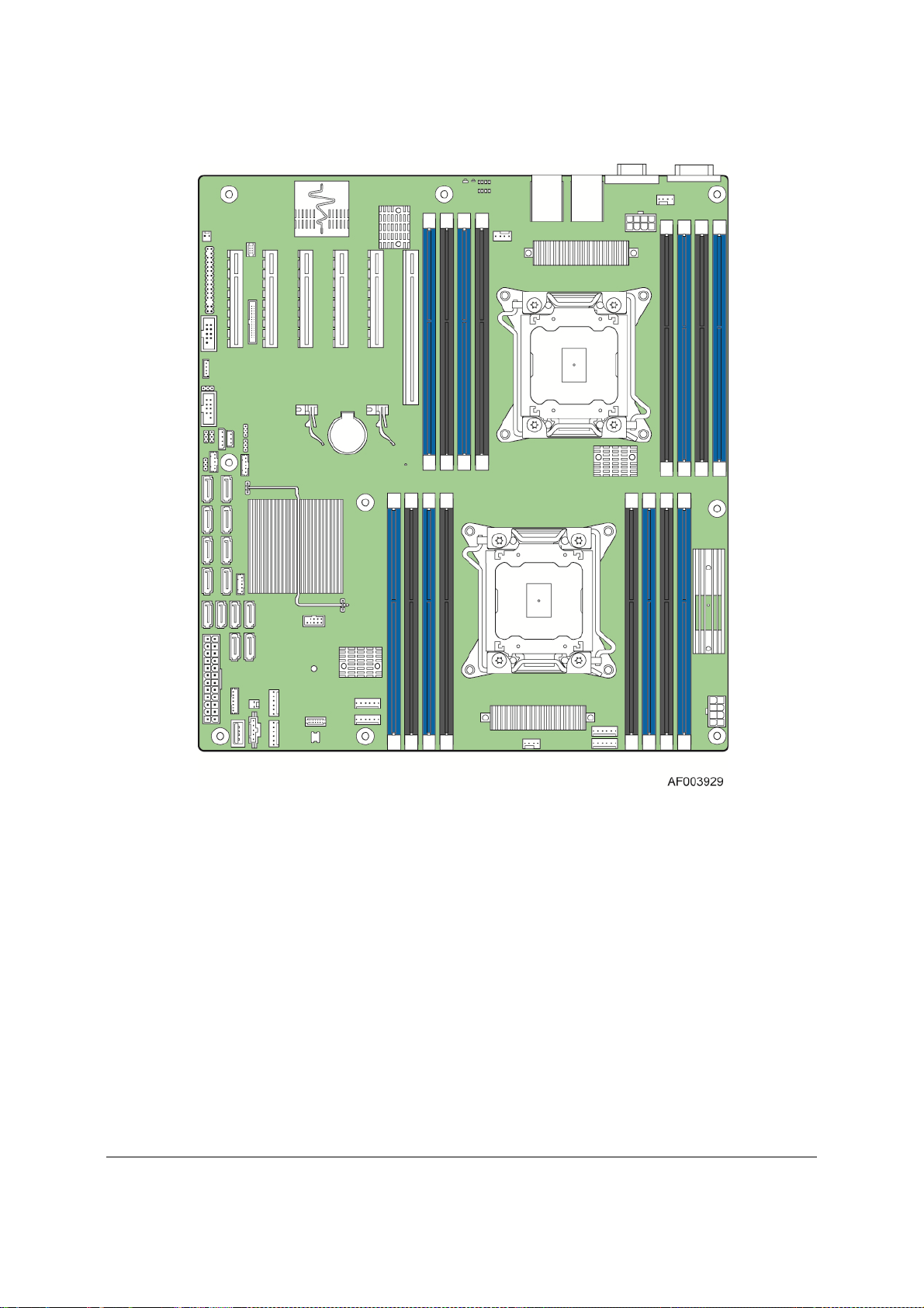
Figure 2. Intel® Server Board S2600CP2, Dual NIC
6 Revision 1.1
Intel order number G26942-003
Page 23
Intel® Server Board S2600CP and Server System P4000CP TPS Intel® Server Board S2600CP Overview
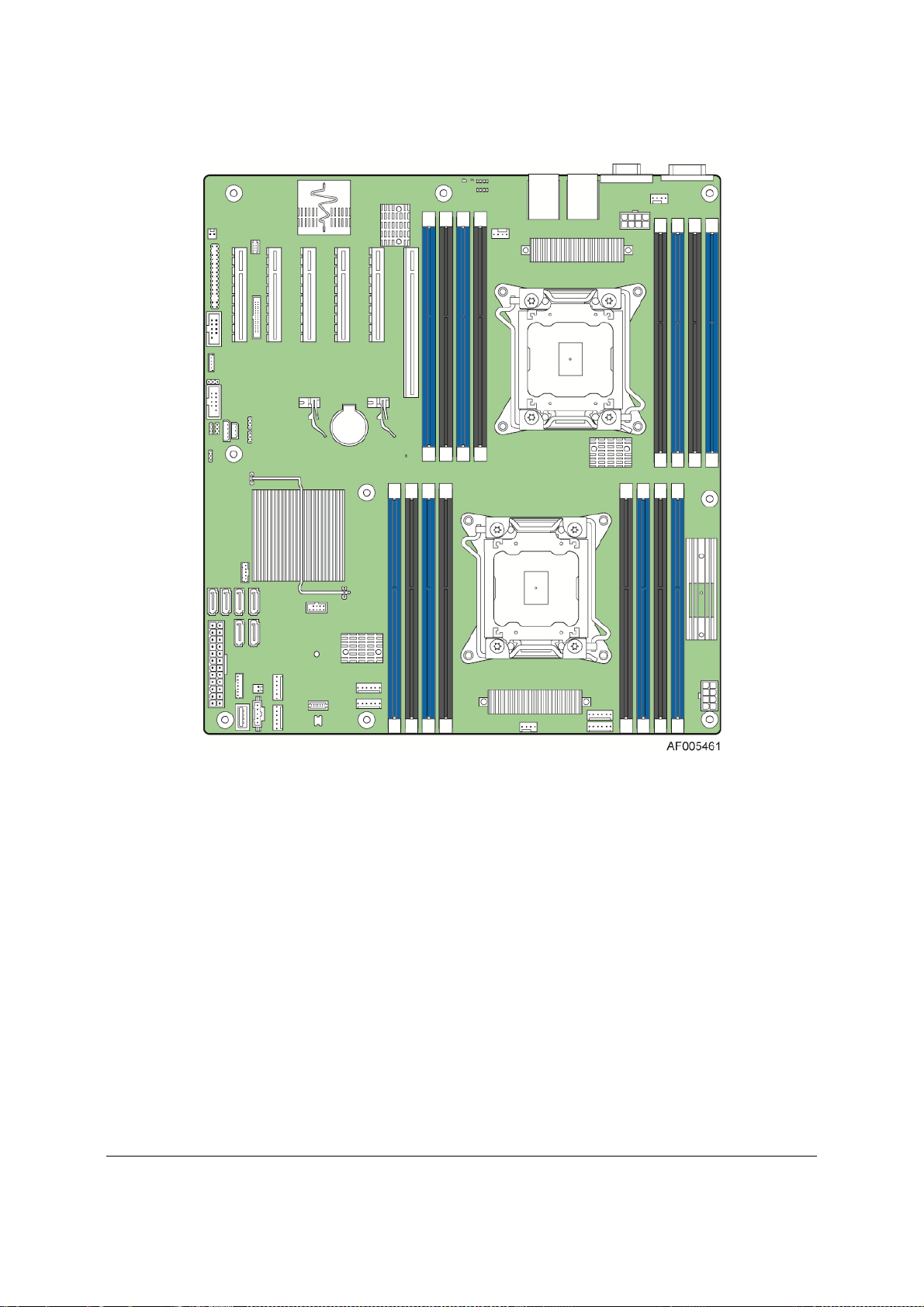
Figure 3. Intel® Server Board S2600CP2J, Dual NIC
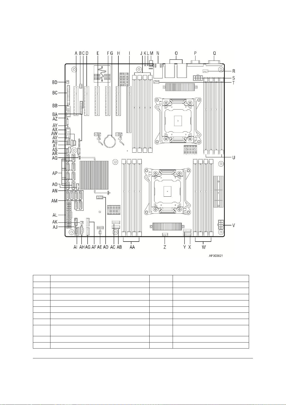
2.2.1 Server Board Connector and Component Layout
The following figure shows the layout of the server board. Each connector and major component
is identified by a number or letter, and a description is given below the figure.
Revision 1.1 7
Intel order number G26942-003
Page 24
Intel® Server Board S2600CP Overview Intel® Server Board S2600CP and Server System P4000CP TPS
Callout Description Callout Description
A Slot 1, PCI Express* Gen3 AC System Fan 4 connector
B RMM4 LITE AD Internal eUSB SSD
C RMM4 NIC AE TPM
D Slot 2, PCI Express* Gen3 AF System Fan 2
E Slot 3, PCI Express* Gen3, open-ended AG System Fan 1
F Slot 4, PCI Express* Gen3 AH PMBus
G Battery AI Type-A USB
Slot 5, PCI Express* Gen3, from second
H
processor, open-ended
I Slot 6, PCI Express* Gen3, support riser card AK HDD activity LED
J DIMM E1/E2/F1/F2 AL Main Power
8 Revision 1.1
Intel order number G26942-003
AJ LCP
Page 25

Intel® Server Board S2600CP and Server System P4000CP TPS Intel® Server Board S2600CP Overview
Callout Description Callout Description
K System Status LED AM SATA 3G connector
L ID LED AN SATA 6G connector
M Diagnostic LED AO SATA SGPIO
SATA/SAS 3G connector (NOT
N NIC 3/4 (only on Intel® Server Board S2600CP4) AP
O USB 0/1/2/3, NIC 1,2 AQ SAS SGPIO 2
P VGA AR Password Clear
Q Serial Port A AS SAS SGPIO 1
R Processor 2 Fan connector AT IPMB
S Processor 2 Power connector AU ME Force Update
T System Fan 7 connector AV BMC Force Update
U DIMM H1/H2/G1/G2 AW HSBP_I2C
V Processor 1 Power connector AX USB to front panel
W DIMM A1/A2/B1/B2 AY BIOS Default
X System Fan 5 connector AZ
Y System Fan 6 connector BA BIOS Recovery
Z Processor 1 Fan connector BB Serial B connector
AA DIMM C1/C2/D1/D2 BC
AB System Fan 3 connector BD Chassis Intrusion
available on Intel® Server Board
S2600CP2J)
Intel C600 RAID Upgrade key
connector
SSI Front Panel (24-pin) and NIC 3/4
LED (4-pin)
Figure 4. Major Board Components
Revision 1.1 9
Intel order number G26942-003
Page 26
Intel® Server Board S2600CP Overview Intel® Server Board S2600CP and Server System P4000CP TPS
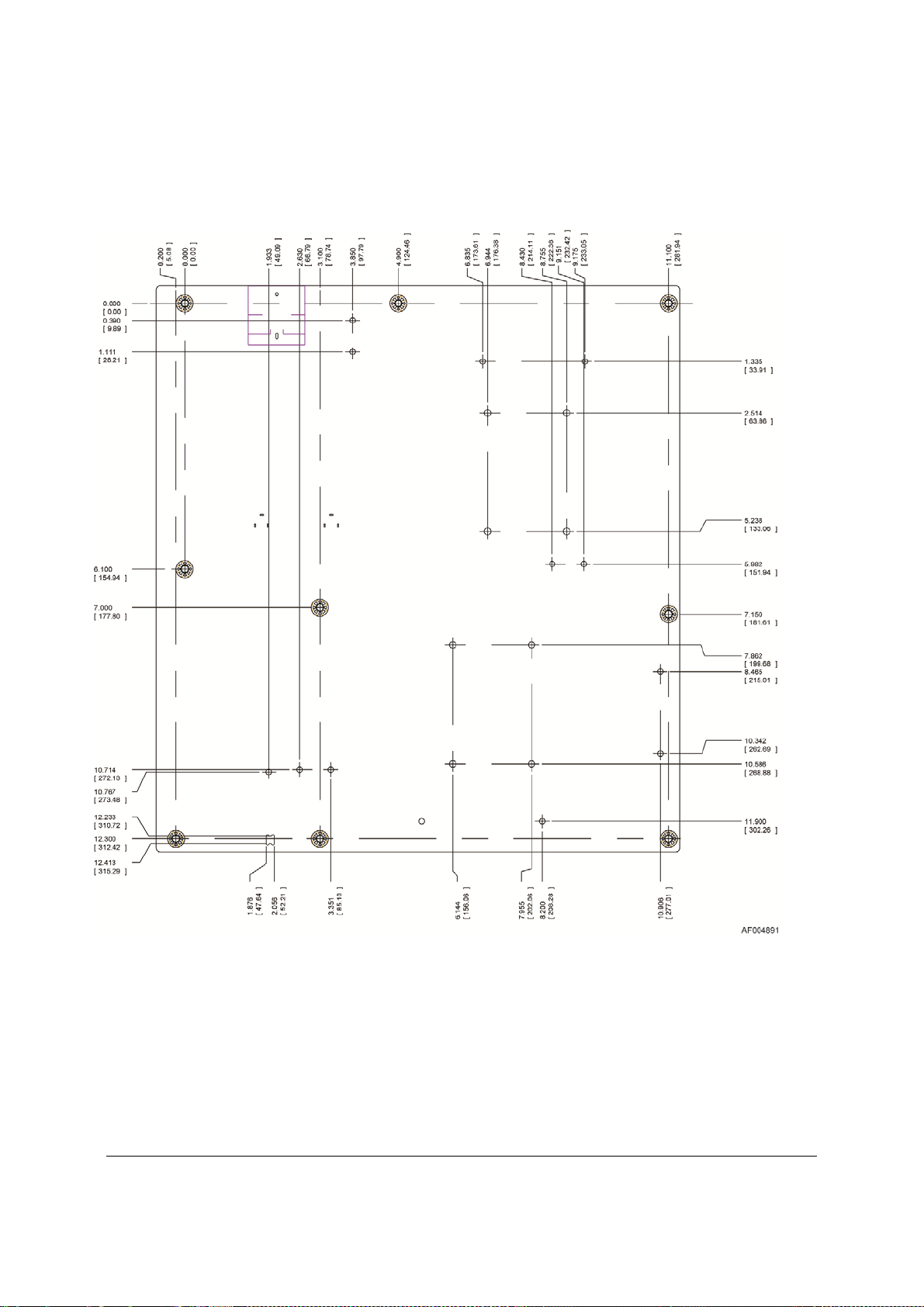
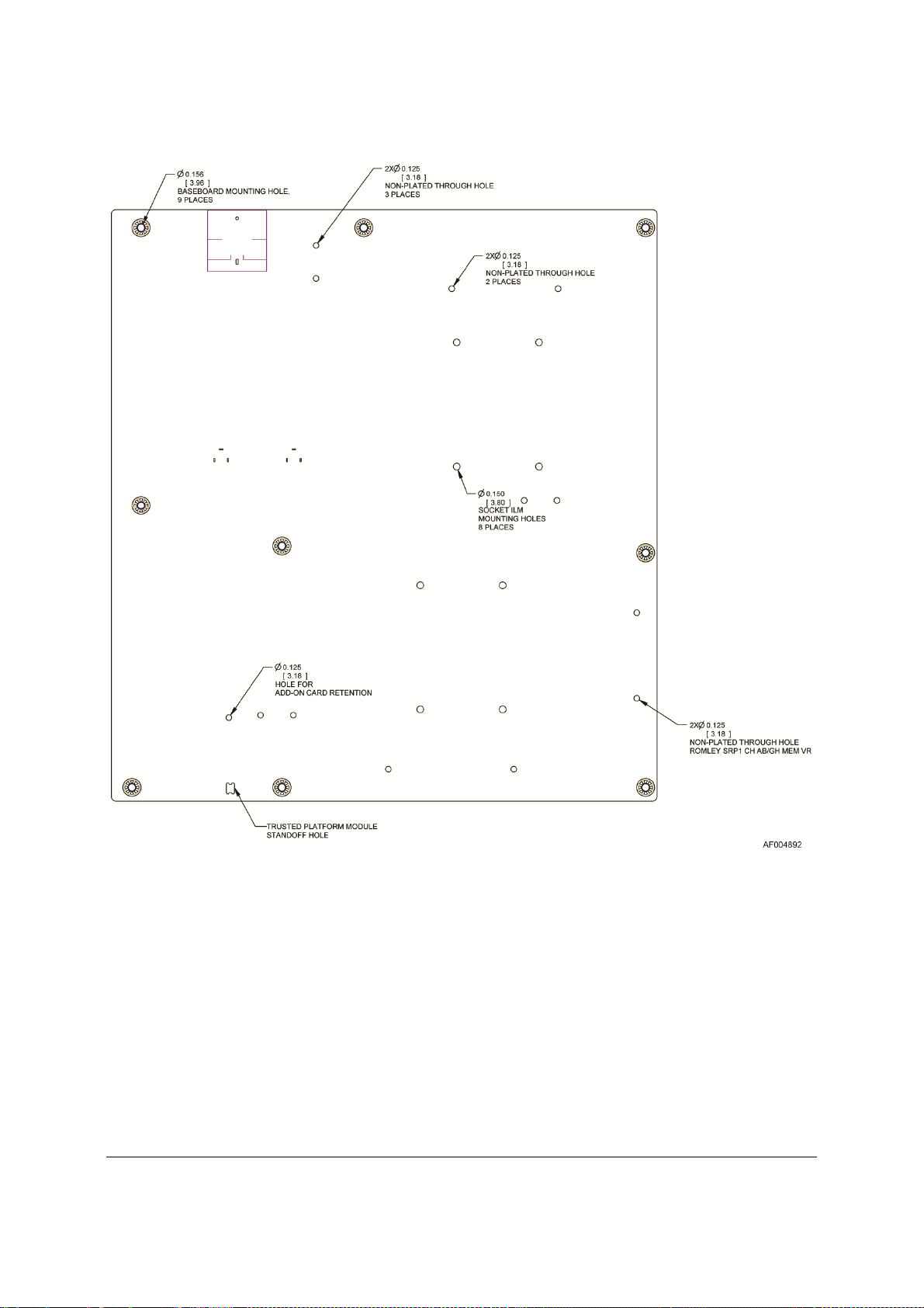
2.2.2 Server Board Mechanical Drawings
Figure 5. Mounting Hole Locations (1 of 2)
10 Revision 1.1
Intel order number G26942-003
Page 27
Intel® Server Board S2600CP and Server System P4000CP TPS Intel® Server Board S2600CP Overview
Figure 6. Mounting Hole Locations (2 of 2)
Revision 1.1 11
Intel order number G26942-003
Page 28
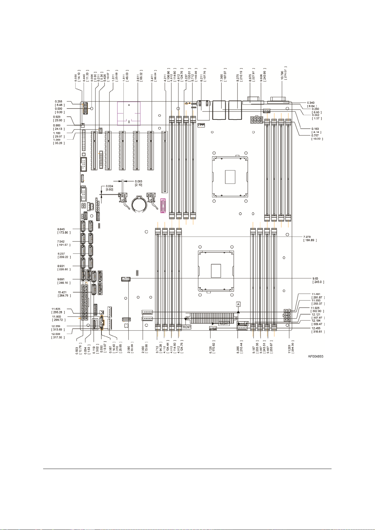
Intel® Server Board S2600CP Overview Intel® Server Board S2600CP and Server System P4000CP TPS
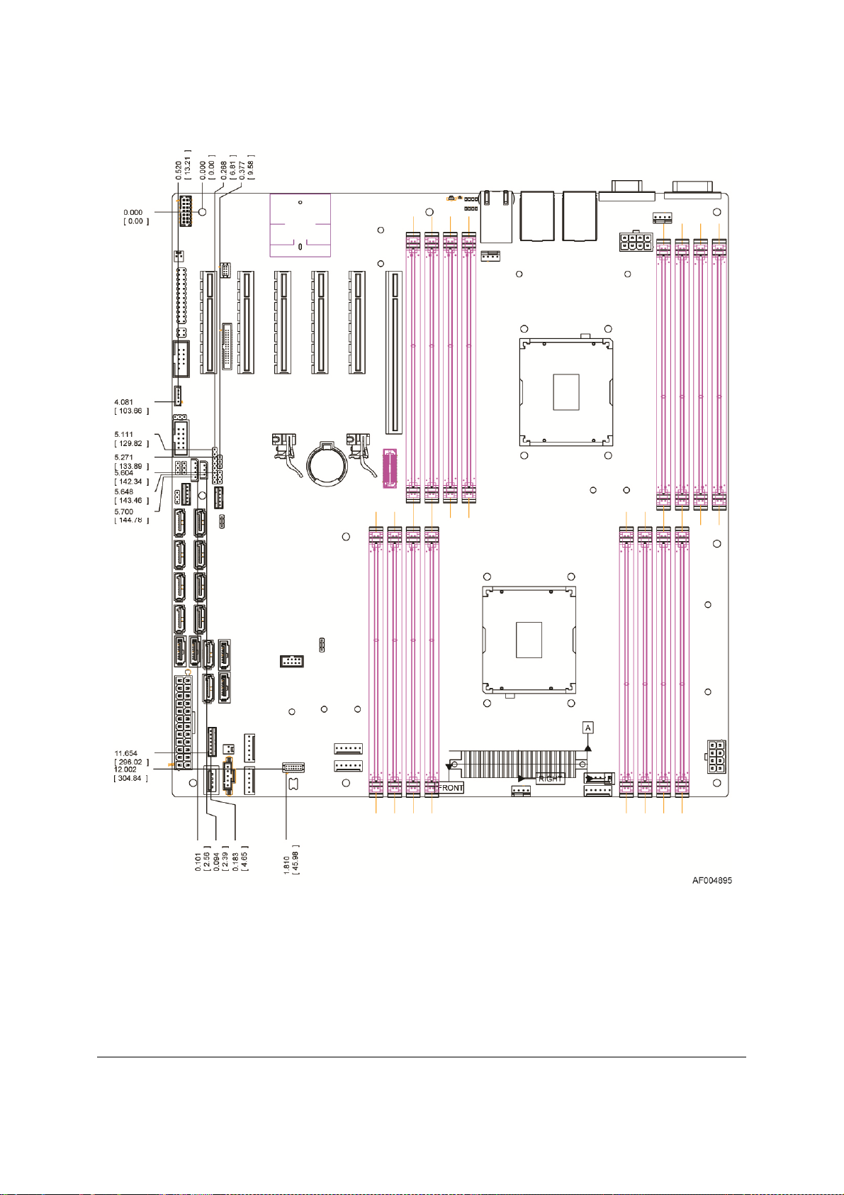
Figure 7. Major Connector Pin-1 Locations (1 of 3)
12 Revision 1.1
Intel order number G26942-003
Page 29

Intel® Server Board S2600CP and Server System P4000CP TPS Intel® Server Board S2600CP Overview
Figure 8. Major Connector Pin-1 Locations (2 of 3)
Revision 1.1 13
Intel order number G26942-003
Page 30
Intel® Server Board S2600CP Overview Intel® Server Board S2600CP and Server System P4000CP TPS
Figure 9. Major Connector Pin-1 Locations (3 of 3)
14 Revision 1.1
Intel order number G26942-003
Page 31

Intel® Server Board S2600CP and Server System P4000CP TPS Intel® Server Board S2600CP Overview
Figure 10. Primary Side Keep-out Zone (1 of 2)
Revision 1.1 15
Intel order number G26942-003
Page 32

Intel® Server Board S2600CP Overview Intel® Server Board S2600CP and Server System P4000CP TPS
Figure 11. Primary Side Card-Side Keep-out Zone
Revision 1.1
16
Intel order number G26942-003
Page 33

Intel® Server Board S2600CP and Server System P4000CP TPS Intel® Server Board S2600CP Overview
Figure 12. Second Side Keep-out Zone
Revision 1.1
Intel order number G26942-003
17
Page 34

Intel® Server Board S2600CP Overview Intel® Server Board S2600CP and Server System P4000CP TPS
2.2.3 Server Board Rear I/O Layout
The following drawing shows the layout of the rear I/O components for the server boards.
Callout Description Callout Description
A Serial Port A E NIC Port 3 (top) and 4 (bottom)
B Video F Diagnostics LED’s
NIC Port 1, USB Port 0 (top) and 1
C
(bottom)
NIC Port 2, USB Port 2 (top) and 3
D
(bottom)
G ID LED
H System Status LED
Figure 13. Rear I/O Layout of Intel® Server Board S2600CP4
Revision 1.1
18
Intel order number G26942-003
Page 35

Intel® Server Board S2600CP and Server System P4000CP TPS Intel® Server Board S2600CP Overview
Callout Description Callout Description
A Serial Port A E Diagnostics LED’s
B Video F ID LED
NIC Port 1, USB Port 0 (top) and 1
C
(bottom)
NIC Port 2, USB Port 2 (top) and 3
D
(bottom)
G System Status LED
Figure 14. Rear I/O Layout of Intel® Server Board S2600CP2/S2600CP2J
Revision 1.1
Intel order number G26942-003
19
Page 36

Intel® Server System P4000CP Overview Intel® Server Board S2600CP and Server System P4000CP TPS
3. Intel® Server System P4000CP Overview
The Intel® Server System P4000CP is a server product family including Intel® Server System
P4308CP4MHEN, P4308CP4MHGC and P4208CP4MHGC which are integrated with different
chassis models from Intel
other accessories.
This document provides system level information for the Intel
family. This document will describe the functions and features provided by the integrated server
system. For chassis layout, system boards, power sub-system, cooling sub-system or storage
sub-system, please refer to Intel
Specification.
3.1 Integrated System Family Overview
The dimension of Intel® Server System P4000CP is 17.24 in (438 mm) x 6.81 in (173mm) x 25
in (612 mm) (Height X Width X Depth).
®
Server Chassis P4000M family, Intel® Server Board S2600CP4 and
®
Server System P4000CP product
®
Server Chassis P4000M Family Technical Product
The color of Intel
®
Server System P4000CP is cosmetic black (GE 701 or equivalent), with
service parts as Intel blue, and hot swap parts as Intel green.
®
Intel
Server System P4308CP4MHEN includes:
®
Server Board S2600CP4
®
Server Chassis P4308XXMXXMHEN
®
C600 RAID Upgrade Key RKSATA8
Server Chassis P4308XXMXXMHEN includes a fixed single 550W non-redundant 80+
Intel
Intel
Intel
Intel
®
Silver power supply and one 8x3.5” hot-swap HDD cage allows support for up to eight hot-swap
SATA/SAS drives. Two tachometer output fans (120mmX38mm) are mounted at the front edge
of the chassis and one air duct for Intel
®
Server Board. Three 5.25-inch half-height peripheral
bays are available for the installation of a floppy drive, CD-ROM drive, and/or other accessories.
The standard chassis configuration is pedestal.
®
Intel
Server System P4308CP4MHGC includes:
Intel
Intel
Intel
®
Intel
hot-swap HDD cage allows support for up to eight hot-swap SATA/SAS drives. Five redundant
hot-swap fans (80x38mm) at the front edge of the chassis and one air duct for Intel
®
Server Board S2600CP4
®
Server Chassis P4308XXMXXMHGC
®
C600 RAID Upgrade Key RKSATA8
Server Chassis P4308XXMXXMHGC includes two 750-W redundant PSUs and one 8x3.5”
®
Server
Board. Three 5.25-inch half-height peripheral bays are available for the installation of a floppy
drive, CD-ROM drive, and/or other accessories. The standard chassis configuration is pedestal.
®
Intel
Server System P4208CP4MHGC includes:
Intel
Intel
Revision 1.1
20
®
Server Board S2600CP4
®
Server Chassis P4208XXMXXMHGC
Intel order number G26942-003
Page 37

Intel® Server Board S2600CP and Server System P4000CP TPS Intel® Server System P4000CP Overview
Intel C600 RAID Upgrade Key RKSAS8
®
Server Chassis P4208XXMXXMHGC includes two 750-W redundant PSU and one 8x2.5"
Intel
hot-swap HDD cage allows support for up to eight 2.5" hot-swap SATA/SAS drives. Five
redundant hot-swap fans (80x38mm) at the front edge of the chassis and one air duct for Intel
®
Server Board. Three 5.25-inch half-height peripheral bays are available for the installation of a
floppy drive, CD-ROM drive, and/or other accessories. The standard chassis configuration is
pedestal.
The following table summarizes the Intel
®
Server System P4000CP features:
Table 2. Intel® Server System P4000CP family Features
Feature Description
Processors Support for one or two Intel® Xeon® E5-2600 Processor(s)
8 GT/s Intel
LGA 2011 Socket
Thermal Design Power up to 135-W
Memory Eight memory channels (four channels for each processor socket)
Channels A, B, C, D, E, F, G and H
Support for 800/1066/1333/1600 MHz/s Registered DDR3 Memory (RDIMM),
Unbuffered DDR3 memory ((UDIMM) and Load Reduced DDR3 memory (LRDIMM)
DDR3 standard I/O voltage of 1.5V and DDR3 Low Voltage of 1.35V
Refer to chapter 4.2.2 for detail information for memory support.
Chipset Intel® C600 -A chipset with support for Intel® C600 RAID Upgrade Keys
Cooling Fan Support Two processor fans (4-pin headers)
Six front system fans (6-pin headers)
One rear system fan (4-pin header)
Add-in Card Slots Support up to six expansion slots
From first processor:
o Slot 1: PCIe Gen III x4/x8 electrical with x8 physical connector
o Slot 2: PCIe Gen III x8 electrical with x8 physical connector
o Slot 3: PCIe Gen III x8 electrical with x8 open-ended physical connector
o Slot 4: PCIe Gen III x8 electrical with x8 physical connector
o Slot 6: PCIe Gen III x8 electrical with x16 connector, support riser card.
From second processor:
o Slot 5: PCIe Gen III x8 electrical with x8 open-ended physical connector
PCIe slot 5 is functional only when the second processor is installed.
Hard Drive and Optical
Drive Support
RAID Support Intel RSTe SW RAID 0/1/10/5
External I/O Connectors One DB-15 video connector
Two SATA connectors at 6 Gbps and four SATA connectors at 3 Gbps. The 6 Gbps
connectors are recommended connectors for ODDs.
Up to eight SATA/SAS connectors at 3 Gbps with optional Intel
Upgrade Keys
LSI SW RAID 0/1/10
One DB9 serial port A connection
Support two or four 10/100/1000Mb NIC
Four USB 2.0 ports
®
Quick Path Interconnect (Intel® QPI)
®
C600 RAID
Revision 1.1
21
Intel order number G26942-003
Page 38

Intel® Server System P4000CP Overview Intel® Server Board S2600CP and Server System P4000CP TPS
®
Feature Description
Internal I/O
Connectors/Headers
One 2x5 pin connector providing front panel support for two USB ports
One internal Type-A USB 2.0 port
One internal USB port to support low profile eUSB SSD
One DH-10 serial Port B connector
One combined header consists of a 24-pin SSI-EEB compliant front panel header
and a 4-pin header for optional NIC3/4 LED
One 1x7pin header for optional Intel
®
Local Control Panel support
Video Support Integrated Matrox* G200 2D Video Graphics controller
LAN Four Gigabit network through Intel® I350 10/100/1000 integrated MAC and PHY
controller
Server Management Onboard ServerEngines* LLC Pilot III* Controller
Support for Intel
®
Intel
Light-Guided Diagnostics on field replaceable units
Support for Intel
Support for Intel
®
Remote Management Module 4 solutions
®
System Management Software
®
Intelligent Power Node Manager (Need PMBus-compliant power
supply)
BIOS Flash Winbond* W25Q64BV
Form Factor SSI EEB (12”x13”)
Compatible Intel® Server
Server Chassis P4000M chassis
Intel
Chassis
3.2 Intel® Server System P4000CP Family View
3.2.1 Intel® Server System P4308CP4MHEN View
A. 550-W Fixed Power supply
B. I/O Ports
C. Alternate RMM4 Knockout
D. PCI Add-in Board Slot Covers
Revision 1.1
22
Intel order number G26942-003
Page 39

Intel® Server Board S2600CP and Server System P4000CP TPS Intel® Server System P4000CP Overview
E. AC Input Power Connector
F. Serial Port Knockout
G. A Kensington* Cable Lock Mounting Hole
H. Padlock Loop
I. Alternate RMM4 Knockout
J. Front Control Panel
K. 5.25” Peripheral Bays
L. Fixed System Fan
M. Heat-sink
N. Intel
O. 8x3.5” Hot-swap HDD Cage
P. Intel
Q. PCI-e Retainer
®
Server Board S2600CP4
®
RAID C600 Upgrade Key RKSATA8
Figure 15. Intel® Server System P4308CP4MHEN View
Note: Airduct is not shown.
3.2.2 Intel® Server System P4308CP4MHGC View
A. 750-W Redundant Power Supply
B. AC Input Power Connector
C. I/O Ports
D. Alternate RMM4 Knockout
E. PCI Add-in Board Slot Covers
F. Serial Port Knockout
G. A Kensington* Cable Lock Mounting Hole
H. Padlock Loop
I. Alternate RMM4 Knockout
J. Front Control Panel
K. Hot-swap System Fan
L. 5.25” Peripheral Bays
M. Heat-sink
N. Intel
O. 8x3.5” Hot-swap HDD Cage
®
Server Board S2600CP4
Revision 1.1
Intel order number G26942-003
23
Page 40

Intel® Server System P4000CP Overview Intel® Server Board S2600CP and Server System P4000CP TPS
P. Intel® RAID C600 Upgrade Key RKSATA8
Q. PCI-e Retainer
Figure 16. Intel® Server System P4308CP4MHGC View
Note: Airduct is not shown.
3.2.3 Intel® Server System P4208CP4MHGC View
Figure 17. Intel® Server System P4208CP4MHGC View
Note: Airduct is not shown.
A. 750-W Redundant Power Supply
B. AC Input Power Connector
C. I/O Ports
D. Alternate RMM4 Knockout
E. PCI Add-in Board Slot Covers
F. Serial Port Knockout
G. A Kensington* Cable Lock Mounting Hole
H. Padlock Loop
I. Alternate RMM4 Knockout
J. Front Control Panel
K. Hot-swap System Fan
L. 5.25” Peripheral Bays
M. Heat-sink
N. 8x3.5” Hot-swap HDD Cage
O. Intel
P. EMI Cover
Q. Intel
R. PCI-e Retainer
®
Server Board S2600CP4
®
RAID C600 Upgrade Key RKSAS8
Revision 1.1
24
Intel order number G26942-003
Page 41

Intel® Server Board S2600CP and Server System P4000CP TPS Intel® Server Board S2600CP Functional Architecture
4. Intel® Server Board S2600CP Functional Architecture
The architecture and design of the Intel® Server Board S2600CP is based on the Intel® Xeon
E5-2600 processor, the Intel
®
C602 or C602J chipset, the Intel® Ethernet Controller I350 GbE
controller chip, and the Server Engines* Pilot-III Server Management Controller. This chapter
provides a high-level description of the functionality associated with each chipset component
and the architectural blocks that make up the server boards.
Figure 18. Intel® Server Board S2600CP2/S2600CP4 Functional Block Diagram with Intel® C602
chipset
Revision 1.1
Intel order number G26942-003
25
Page 42

Intel® Server Board S2600CP Functional Architecture Intel® Server Board S2600CP and Server System P4000CP TPS
Figure 19. Intel® Server Board S2600CP2J Functional Block Diagram with Intel® C602J chipset
Revision 1.1
26
Intel order number G26942-003
Page 43

Intel® Server Board S2600CP and Server System P4000CP TPS Intel® Server Board S2600CP Functional Architecture
4.1 Processor Support
The server board includes two Socket-R (LGA2011) processor sockets and can support two
processors from Intel
®
Xeon® processor E5-2600 product family with a Thermal Design Power
(TDP) of up to 135W.
Previous generation Intel
®
Xeon® processors are not supported on the Intel server boards
described in this document.
Visit the Intel web site for a complete list of supported processors.
4.1.1 Processor Socket Assembly
Each processor socket of the server board is pre-assembled with an Independent Latching
Mechanism (ILM) and Back Plate which allow for secure placement of the processor and
processor heat to the server board.
The illustration below identifies each sub-assembly component.
Heat Sink
Server Board
Independent Latching
Mechanism (ILM)
Back Plate
Figure 20. Processor Socket Assembly
4.1.2 Processor Population Rules
Note: Although the server board does support dual-processor configurations consisting of
different processors that meet the defined criteria below, Intel does not perform validation
testing of this configuration.
Intel recommends that identical processors be installed.
When using a single processor configuration, the processor must be installed into the processor
socket labeled CPU1.
When two processors are installed, the following population rules apply:
For optimal system performance in dual-processor configurations,
Revision 1.1
Intel order number G26942-003
27
Page 44

Intel® Server Board S2600CP Functional Architecture Intel® Server Board S2600CP and Server System P4000CP TPS
Both processors must be of the same processor family.
Both processors must have the same number of cores
Both processors must have the same cache sizes for all levels of processor cache
memory.
Processors with different core frequencies can be mixed in a system, given the prior
rules are met. If this condition is detected, all processor core frequencies are set to the
lowest common denominator (highest common speed) and an error is reported.
Processors which have different QPI link frequencies may operate together if they are
otherwise compatible and if a common link frequency can be selected. The common link
frequency would be the highest link frequency that all installed processors can achieve.
Processor stepping within a common processor family can be mixed as long as it is
listed in the processor specification updates published by Intel Corporation.
The following table describes mixed processor conditions and recommended actions for all
®
Intel
server boards and Intel server systems designed around the Intel® Xeon® processor E5-
2600 product family and Intel
®
C600 chipset product family architecture. The errors fall into one
of the following three categories:
Fatal: If the system can boot, it pauses at a blank screen with the text “Unrecoverable
fatal error found. System will not boot until the error is resolved” and “Press <F2> to
enter setup”, regardless of whether the “Post Error Pause” setup option is enabled or
disabled.
When the operator presses the <F2> key on the keyboard, the error message is
displayed on the Error Manager screen, and an error is logged to the System Event Log
(SEL) with the POST Error Code.
The system cannot boot unless the error is resolved. The user needs to replace the
faulty part and restart the system.
For Fatal Errors during processor initialization, the System Status LED will be set to a
steady Amber color, indicating an unrecoverable system failure condition.
Major: If the “Post Error Pause” setup option is enabled, the system goes directly to the
Error Manager to display the error, and logs the POST Error Code to SEL. Operator
intervention is required to continue booting the system.
Otherwise, if “POST Error Pause” is disabled, the system continues to boot and no
prompt is given for the error, although the Post Error Code is logged to the Error
Manager and in a SEL message.
Minor: The message is displayed on the screen or on the Error Manager screen, and
the POST Error Code is logged to the SEL. The system continues booting in a degraded
state. The user may want to replace the erroneous unit. The POST Error Pause option
setting in the BIOS setup does not have any effect on this error.
Revision 1.1
28
Intel order number G26942-003
Page 45

Intel® Server Board S2600CP and Server System P4000CP TPS Intel® Server Board S2600CP Functional Architecture
Table 3. Mixed Processor Configurations
Error Severity System Action
Processor family not
Identical
Processor model not
Identical
Processor cores/threads not
identical
Processor cache not
identical
Processor frequency (speed)
not identical
Fatal The BIOS detects the error condition and responds as follows:
Logs the POST Error Code into the System Event Log (SEL).
Alerts the BMC to set the System Status LED to steady Amber.
Displays “0194: Processor family mismatch detected”
message in the Error Manager.
Takes Fatal Error action (see above) and will not boot until the
fault condition is remedied.
Fatal The BIOS detects the error condition and responds as follows:
Logs the POST Error Code into the System Event Log (SEL).
Alerts the BMC to set the System Status LED to steady Amber.
Displays “0196: Processor model mismatch detected”
message in the Error Manager.
Takes Fatal Error action (see above) and will not boot until the
fault condition is remedied.
Fatal The BIOS detects the error condition and responds as follows:
Logs the POST Error Code into the SEL.
Alerts the BMC to set the System Status LED to steady Amber.
Displays “0191: Processor core/thread count mismatch
detected” message in the Error Manager.
Takes Fatal Error action (see above) and will not boot until the
fault condition is remedied.
Fatal The BIOS detects the error condition and responds as follows:
Logs the POST Error Code into the SEL.
Alerts the BMC to set the System Status LED to steady Amber.
Displays “0192: Processor cache size mismatch detected
message in the Error Manager.
Takes Fatal Error action (see above) and will not boot until the
fault condition is remedied.
Fatal The BIOS detects the processor frequency difference, and responds
as follows:
Adjusts all processor frequencies to the highest common
frequency.
No error is generated – this is not an error condition.
Continues to boot the system successfully.
If the frequencies for all processors cannot be adjusted to be the
same, then this is
Logs the POST Error Code into the SEL.
Alerts the BMC to set the System Status LED to steady Amber.
Does not disable the processor.
Displays “0197: Processor speeds unable to synchronize”
message in the Error Manager.
Takes Fatal Error action (see above) and will not boot until the
fault condition is remedied.
an error, and the BIOS responds as follows:
Revision 1.1
Intel order number G26942-003
29
Page 46

Intel® Server Board S2600CP Functional Architecture Intel® Server Board S2600CP and Server System P4000CP TPS
Error Severity System Action
Processor Intel® QuickPath
Interconnect link frequencies
not identical
Processor microcode update
missing
Processor microcode update
failed
Fatal The BIOS detects the QPI link frequencies and responds as follows:
Adjusts all QPI interconnect link frequencies to highest common
frequency.
No error is generated – this is not an error condition.
Continues to boot the system successfully.
If the link frequencies for all QPI links cannot be adjusted to be the
same, then this is
Logs the POST Error Code into the SEL.
Alerts the BMC to set the System Status LED to steady Amber.
Displays “0195: PProcessor Intel(R) QPI link frequencies
unable to synchronize” message in the Error Manager.
Does not disable the processor. Takes Fatal Error action (see
above) and will not boot until the fault condition is remedied.
Minor The BIOS detects the error condition and responds as follows:
Logs the POST Error Code into the SEL.
Displays “818x: Processor 0x microcode update not found”
message in the Error Manager or on the screen.
The system continues to boot in a degraded state, regardless of
the setting of POST Error Pause in the Setup.
Major The BIOS detects the error condition and responds as follows:
Logs the POST Error Code into the SEL.
Displays “816x: Processor 0x unable to apply microcode
update” message in the Error Manager or on the screen.
Takes Major Error action. The system may continue to boot in a
degraded state, depending on the setting of POST Error Pause in
Setup, or may halt with the POST Error Code in the Error
Manager waiting for operator intervention.
an error, and the BIOS responds as follows:
Revision 1.1
30
Intel order number G26942-003
Page 47

Intel® Server Board S2600CP and Server System P4000CP TPS Intel® Server Board S2600CP Functional Architecture
4.2 Processor Functions Overview
With the release of the Intel® Xeon® processor E5-2600 product family, several key system
components, including the CPU, Integrated Memory Controller (iMC), and Integrated IO Module
(IIO), have been combined into a single processor package and feature per socket; two Intel
QuickPath Interconnect point-to-point links capable of up to 8.0 GT/s, up to 40 lanes of Gen 3
PCI Express* links capable of 8.0 GT/s, and 4 lanes of DMI2/PCI Express* Gen 2 interface with
a peak transfer rate of 5.0 GT/s. The processor supports up to 46 bits of physical address space
and 48-bit of virtual address space.
The following sections will provide an overview of the key processor features and functions that
help to define the performance and architecture of the server board.
Processor Feature Details:
®
Up to 8 execution cores
®
Each core supports two threads (Intel
Hyper-Threading Technology), up to 16 threads
per socket
46-bit physical addressing and 48-bit virtual addressing
1 GB large page support for server applications
A 32-KB instruction and 32-KB data first-level cache (L1) for each core
A 256-KB shared instruction/data mid-level (L2) cache for each core
Up to 20 MB last level cache (LLC): up to 2.5 MB per core instruction/data last level
cache (LLC), shared among all cores
Supported Technologies:
Intel
Intel
Intel
Intel
Intel
Intel
Intel
Intel
Execute Disable Bit
Intel
Intel
Data Direct I/O (DDIO)
Enhanced Intel
®
Virtualization Technology (Intel® VT)
®
Virtualization Technology for Directed I/O (Intel® VT-d)
®
Trusted Execution Technology (Intel® TXT)
®
64 Architecture
®
Streaming SIMD Extensions 4.1 (Intel® SSE4.1)
®
Streaming SIMD Extensions 4.2 (Intel® SSE4.2)
®
Advanced Vector Extensions (Intel® AVX)
®
Hyper-Threading Technology
®
Turbo Boost Technology
®
Intelligent Power Technology
®
SpeedStep Technology
4.2.1 Intel® QuickPath Interconnect
The Intel® QuickPath Interconnect is a high speed, packetized, point-to-point interconnect used
in the processor. The narrow high-speed links stitch together processors in distributed shared
memory and integrated I/O platform architecture. It offers much higher bandwidth with low
latency. The Intel
Revision 1.1
®
QuickPath Interconnect has an efficient architecture allowing more
Intel order number G26942-003
31
Page 48

Intel® Server Board S2600CP Functional Architecture Intel® Server Board S2600CP and Server System P4000CP TPS
interconnect performance to be achieved in real systems. It has a snoop protocol optimized for
low latency and high scalability, as well as packet and lane structures enabling quick
completions of transactions. Reliability, availability, and serviceability features (RAS) are built
into the architecture.
The physical connectivity of each interconnect link is made up of twenty differential signal pairs
plus a differential forwarded clock. Each port supports a link pair consisting of two uni-directional
links to complete the connection between two components. This supports traffic in both
directions simultaneously. To facilitate flexibility and longevity, the interconnect is defined as
having five layers: Physical, Link, Routing, Transport, and Protocol.
The Intel
®
QuickPath Interconnect includes a cache coherency protocol to keep the distributed
memory and caching structures coherent during system operation. It supports both low-latency
source snooping and a scalable home snoop behavior. The coherency protocol provides for
direct cache-to-cache transfers for optimal latency.
4.2.2 Integrated Memory Controller (IMC) and Memory Subsystem
CPU 1
2 DIMMs/Ch
Figure 21. Memory Subsystem for Intel® Server Board S2600CP
Integrated into the processor is a memory controller. Each processor provides four DDR3
channels that support the following:
Unbuffered DDR3 and registered DDR3 DIMMs
LR DIMM (Load Reduced DIMM) for buffered memory solutions demanding higher
capacity memory subsystems
Independent channel mode or lockstep mode
Data burst length of eight cycles for all memory organization modes
Memory DDR3 data transfer rates of 800, 1066, 1333, and 1600 MT/s
64-bit wide channels plus 8-bits of ECC support for each channel
DDR3 standard I/O Voltage of 1.5 V and DDR3 Low Voltage of 1.35 V
1-Gb, 2-Gb, and 4-Gb DDR3 DRAM technologies supported for these devices:
o UDIMM DDR3 – SR x8 and x16 data widths, DR – x8 data width
o RDIMM DDR3 – SR,DR, and QR – x4 and x8 data widths
o LRDIMM DDR3 – QR – x4 and x8 data widths with direct map or with rank
multiplication
Up to 8 ranks supported per memory channel, 1, 2 or 4 ranks per DIMM
Open with adaptive idle page close timer or closed page policy
CPU 2
2 DIMMs/Ch
Revision 1.1
32
Intel order number G26942-003
Page 49

Intel® Server Board S2600CP and Server System P4000CP TPS Intel® Server Board S2600CP Functional Architecture
Per channel memory test and initialization engine can initialize DRAM to all logical zeros
with valid ECC (with or without data scrambler) or a predefined test pattern
Isochronous access support for Quality of Service (QoS)
Minimum memory configuration: independent channel support with 1 DIMM populated
Integrated dual SMBus master controllers
Command launch modes of 1n/2n
RAS Support:
o Rank Level Sparing and Device Tagging
o Demand and Patrol Scrubbing
o DRAM Single Device Data Correction (SDDC) for any single x4 or x8 DRAM
device. Independent channel mode supports x4 SDDC. x8 SDDC requires
lockstep mode
o Lockstep mode where channels 0 and 1 and channels 2 and 3 are operated in
lockstep mode
o Data scrambling with address to ease detection of write errors to an incorrect
address.
o Error reporting by Machine Check Architecture
o Read Retry during CRC error handling checks by iMC
o Channel mirroring within a socket
CPU1 Channel Mirror Pairs (A,B) and (C,D)
CPU2 Channel Mirror Pairs (E,F) and (G,H)
o Error Containment Recovery
Improved Thermal Throttling with dynamic Closed Loop Thermal Throttling (CLTT)
Memory thermal monitoring support for DIMM temperature
4.2.2.1 Supported Memory
Table 4. UDIMM Support
Speed (MT/s) and Voltage Validated by
Ranks Per
DIMM and Data
Width
SRx8 Non-
ECC
DRx8 Non-
ECC
SRx16 Non-
ECC
SRx8 ECC 1GB 2GB 4GB 1066, 1333 1066, 1333 1066 1066, 1333
DRx8 ECC 2GB 4GB 8GB 1066, 1333 1066, 1333 1066 1066, 1333
Memory Capacity Per
DIMM
1GB 2GB 4GB n/a 1066, 1333 n/a 1066, 1333
2GB 4GB 8GB n/a 1066, 1333 n/a 1066, 1333
512MB 1GB 2GB n/a 1066, 1333 n/a 1066, 1333
Slot per Channel (SPC) and DIMM Per Channel (DPC)
Intel® Server Board S2600CP (2 Slots per Channel)
1DPC
1.35V 1.5V 1.35V 1.5V
2DPC
Revision 1.1
33
Intel order number G26942-003
Page 50

Intel® Server Board S2600CP Functional Architecture Intel® Server Board S2600CP and Server System P4000CP TPS
Table 5. RDIMM Support
Speed (MT/s) and Voltage Validated by Slot per Channel (SPC) and DIMM
Ranks Per
DIMM and
Data Width
SRx8 1GB 2GB 4GB 1066, 1333
Memory Capacity Per
DIMM
1.35V 1.5V 1.35V 1.5V
Intel® Server Board S2600CP (2 Slots per Channel)
1DPC 2DPC
Per Channel (DPC)
1066, 1333,
1600
1066,1333
1066, 1333,
1600
DRx8 2GB 4GB 8GB 1066, 1333
SRx4 2GB 4GB 8GB 1066, 1333
DRx4 4GB 8GB 16GB 1066, 1333
QRx4 8GB 16GB 32GB 800
QRx8 4GB 8GB 16GB 800
1066, 1333,
1600
1066, 1333,
1600
1066, 1333,
1600
1066
1066
1066,1333
1066,1333
1066,1333
800 800
800 800
1066, 1333,
1600
1066, 1333,
1600
1066, 1333,
1600
Table 6. LRDIMM Support
Speed (MT/s) and Voltage Validated by Slot per
Ranks Per DIMM and
Data Width
QRx4
(DDP)
QRx8
(P)
Memory Capacity Per
DIMM
16GB 32GB 1066 1066, 1333
8GB 16GB 1066 1066, 1333
Channel (SPC) and DIMM Per Channel (DPC)
2 Slots per Channel
1DPC and 2DPC
1.35V 1.5V
4.2.2.2 Memory Population Rules
Each processor provides four banks of memory, each capable of supporting up to 2 DIMMs.
DIMMs are organized into physical slots on DDR3 memory channels that belong to
processor sockets.
The memory channels from processor socket 1 are identified as Channel A, B, C and D.
The memory channels from processor socket 2 are identified as Channel E, F, G, and H.
The silk screened DIMM slot identifiers on the board provide information about the
channel, and therefore the processor to which they belong. For example, DIMM_A1 is
the first slot on Channel A on processor 1; DIMM_E1 is the first DIMM socket on
Channel E on processor 2.
The memory slots associated with a given processor are unavailable if the
corresponding processor socket is not populated.
A processor may be installed without populating the associated memory slots provided
and a second processor is installed with associated memory.
Revision 1.1
34
Intel order number G26942-003
In this case, the memory is
Page 51

Intel® Server Board S2600CP and Server System P4000CP TPS Intel® Server Board S2600CP Functional Architecture
shared by the processors. However, the platform suffers performance degradation and
latency due to the remote memory.
Processor sockets are self-contained and autonomous. However, all memory subsystem
support (such as Memory RAS, Error Management,) in the BIOS setup is applied
commonly across processor sockets.
®
On the Intel
Server Board S2600CP a total of 16 DIMM slots are provided (2 CPUs – 4
Channels/CPU, 2 DIMMs/Channel). The nomenclature for DIMM sockets is detailed in the
following table:
Table 7. Intel® Server Board S2600CP DIMM Nomenclature
Processor Socket 1 Processor Socket 2
(0)
Channel A
A1 A2 B1 B2 C1 C2 D1 D2 E1 E2 F1 F2 G1 G2 H1 H2
(1)
Channel B
(2)
Channel C
(3)
Channel D
(0)
Channel E
(1)
Channel F
(2)
Channel G
(3)
Channel H
Figure 22. Intel® Server Board S2600CP DIMM Slot Layout
The following are generic DIMM population requirements that generally apply to both the Intel®
Server Board S2600CP.
Revision 1.1
Intel order number G26942-003
35
Page 52

Intel® Server Board S2600CP Functional Architecture Intel® Server Board S2600CP and Server System P4000CP TPS
DIMM slots on any memory channel must be filled following the “farthest fill first” rule.
A maximum of 8 ranks can be installed on any one channel, counting all ranks in each
DIMM on the channel.
DIMM types (UDIMM, RDIMM, LRDIMM) must not be mixed within or across processor
sockets.
Mixing ECC with non-ECC DIMMs (UDIMMs) is not supported within or across
processor sockets.
Mixing Low Voltage (1.35V) DIMMs with Standard Voltage (1.5V) DIMMs is not
supported within or across processor sockets.
Mixing DIMMs of different frequencies and latencies is not supported within or across
processor sockets.
LRDIMM Rank Multiplication Mode and Direct Map Mode must not be mixed within or
across processor sockets.
Only ECC UDIMMs support Low Voltage 1.35V operation.
QR RDIMMs may only be installed in DIMM Slot 1 or 2 on a channel.
2 DPC QR Low Voltage RDIMMs are not supported.
In order to install 3 QR LRDIMMs on the same channel, they must be operated with
Rank Multiplication as RM = 2.
RAS Modes Lockstep, Rank Sparing, and Mirroring are mutually exclusive in this BIOS.
Only one operating mode may be selected, and it will be applied to the entire system.
If a RAS Mode has been configured, and the memory population will not support it
during boot, the system will fall back to Independent Channel Mode and log and display
errors
Rank Sparing Mode is only possible when all channels that are populated with memory
meet the requirement of having at least 2 SR or DR DIMM installed, or at least one QR
DIMM installed, on each populated channel.
Lockstep or Mirroring Modes require that for any channel pair that is populated with
memory, the memory population on both channels of the pair must be identically sized.
4.2.2.3 Publishing System Memory
The BIOS displays the “Total Memory” of the system during POST if Quite Boot is disabled in
the BIOS setup. This is the total size of memory discovered by the BIOS during POST, and is
the sum of the individual sizes of installed DDR3 DIMMs in the system.
The BIOS displays the “Effective Memory” of the system in the BIOS setup. The term Effective
Memory refers to the total size of all DDR3 DIMMs that are active (not disabled) and not used
as redundant units.
The BIOS provides the total memory of the system in the main page of the BIOS setup. This
total is the same as the amount described by the first bullet above.
If Quite Boot is disabled, the BIOS displays the total system memory on the diagnostic screen at
the end of POST. This total is the same as the amount described by the first bullet above.
4.2.2.4 RAS Features
The server board supports the following memory RAS modes:
Revision 1.1
36
Intel order number G26942-003
Page 53

Intel® Server Board S2600CP and Server System P4000CP TPS Intel® Server Board S2600CP Functional Architecture
Independent Channel Mode
Rank Sparing Mode
Mirrored Channel Mode
Lockstep Channel Mode
Regardless of RAS mode, the requirements for populating within a channel given in the section
4.2.2.2 must be met at all times. Note that support of RAS modes that require matching DIMM
population between channels (Mirrored and Lockstep) require that ECC DIMMs be populated.
Independent Channel Mode is the only mode that supports non-ECC DIMMs in addition to ECC
DIMMs.
For RAS modes that require matching populations, the same slot positions across channels
must hold the same DIMM type with regards to size and organization. DIMM timings do not
have to match but timings will be set to support all DIMMs populated (i.e, DIMMs with slower
timings will force faster DIMMs to the slower common timing modes).
4.2.2.4.1 Independent Channel Mode
Channels can be populated in any order in Independent Channel Mode. All four channels may
be populated in any order and have no matching requirements. All channels must run at the
same interface frequency but individual channels may run at different DIMM timings (RAS
latency, CAS Latency, and so forth).
4.2.2.4.2 Rank Sparing Mode
In Rank Sparing Mode, one rank is a spare of the other ranks on the same channel. The spare
rank is held in reserve and is not available as system memory. The spare rank must have
identical or larger memory capacity than all the other ranks (sparing source ranks) on the same
channel. After sparing, the sparing source rank will be lost.
4.2.2.4.3 Mirrored Channel Mode
In Mirrored Channel Mode, the memory contents are mirrored between Channel 0 and Channel 2
and also between Channel 1 and Channel 3. As a result of the mirroring, the total physical
memory available to the system is half of what is populated. Mirrored Channel Mode requires
that Channel 0 and Channel 2, and Channel 1 and Channel 3 must be populated identically with
regards to size and organization. DIMM slot populations within a channel do not have to be
identical but the same DIMM slot location across Channel 0 and Channel 2 and across Channel
1 and Channel 3 must be populated the same.
4.2.2.4.4 Lockstep Channel Mode
In Lockstep Channel Mode, each memory access is a 128-bit data access that spans Channel 0
and Channel 1, and Channel 2 and Channel 3. Lockstep Channel mode is the only RAS mode
that allows SDDC for x8 devices. Lockstep Channel Mode requires that Channel 0 and Channel
1, and Channel 2 and Channel 3 must be populated identically with regards to size and
organization. DIMM slot populations within a channel do not have to be identical but the same
DIMM slot location across Channel 0 and Channel 1 and across Channel 2 and Channel 3 must
be populated the same.
Revision 1.1
Intel order number G26942-003
37
Page 54

Intel® Server Board S2600CP Functional Architecture Intel® Server Board S2600CP and Server System P4000CP TPS
4.2.3 Processor Integrated I/O Module (IIO)
The processor’s integrated I/O module provides features traditionally supported through chipset
components. The integrated I/O module provides the following features:
4.2.3.1.1 PCI Express Interfaces
The integrated I/O module incorporates the PCI Express interface and supports up to 40 lanes
of PCI Express. Intel
From first processor:
®
Server Board S2600CP supports 6 PCI-e slots from two processors:
o Slot 1: PCIe Gen III x4/x8 electrical with x8 physical connector
o Slot 2: PCIe Gen III x8 electrical with x8 physical connector
o Slot 3: PCIe Gen III x8 electrical with x8 open-ended physical connector
o Slot 4: PCIe Gen III x8 electrical with x8 physical connector
o Slot 6: PCIe Gen III x8 electrical with x16 connector, support riser card.
From second processor:
o Slot 5: PCIe Gen III x8 electrical with x8 open-ended physical connector
Note: PCIe slot 5 is functional only when the second processor is installed.
4.2.3.1.2 DMI2 Interface to the PCH
The platform requires an interface to the legacy Southbridge (PCH) which provides basic,
legacy functions required for the server platform and operating systems. Since only one PCH is
required and allowed for the system, any sockets which do not connect to PCH would use this
port as a standard x4 PCI Express 2.0 interface.
4.2.3.1.3 Integrated IOAPIC
Provides support for PCI Express devices implementing legacy interrupt messages without
interrupt sharing.
4.2.3.1.4 Intel
®
QuickData Technology
Used for efficient, high bandwidth data movement between two locations in memory or from
memory to I/O.
4.3 Intel® C600 Chipset Functional Overview
The following sub-sections will provide an overview of the key features and functions of the
®
Intel
C600-A chipset used on the server board.
Revision 1.1
38
Intel order number G26942-003
Page 55

Intel® Server Board S2600CP and Server System P4000CP TPS Intel® Server Board S2600CP Functional Architecture
Figure 23. Intel® Server Board S2600CP2/S2600CP4 Chipset Functional Block Diagram
Figure 24. Intel® Server Board S2600CP2J Chipset Functional Block Diagram
Revision 1.1
Intel order number G26942-003
39
Page 56

Intel® Server Board S2600CP Functional Architecture Intel® Server Board S2600CP and Server System P4000CP TPS
The Intel® C600 chipset in the Intel® Server Board S2600CP provide a connection point
between various I/O components and Intel
®
Xeon E5-2600 processors, which includes the
following core platform functions:
Digital Media Interface (DMI)
PCI Express* Interface
Serial ATA (SATA) Controller
Serial Attached SCSI (SAS)/SATA Controller (S2600CP2/S2600CP4 only)
AHCI
Rapid Storage Technology
PCI Interface
Low Pin Count (LPC) Interface
Serial Peripheral Interface (SPI)
Compatibility Modules (DMA Controller, Timer/Counters, Interrupt Controller)
Advanced Programmable Interrupt Controller (APIC)
Universal Serial Bus (USB) Controllers
Gigabit Ethernet Controller
RTC
GPIO
Enhanced Power Management
Intel
Manageability
System Management Bus (SMBus 2.0)
Virtualization Technology for Directed I/O (Intel
KVM/Serial Over LAN (SOL) Function
®
Active Management Technology (Intel® AMT)
®
VT-d)
4.3.1 Digital Media Interface (DMI)
Digital Media Interface (DMI) is the chip-to-chip connection between the processor and C600
chipset. This high-speed interface integrates advanced priority-based servicing allowing for
concurrent traffic and true isochronous transfer capabilities. Base functionality is completely
software-transparent, permitting current and legacy software to operate normally.
4.3.2 PCI Express* Interface
The C600 chipset provides up to 8 PCI Express Root Ports, supporting the PCI Express Base
Specification, Revision 2.0. Each Root Port x1 lane supports up to 5 Gb/s bandwidth in each
direction (10 Gb/s concurrent). PCI Express Root Ports 1-4 or Ports 5-8 can independently be
configured to support four x1s, two x2s, one x2 and two x1s, or one x4 port widths.
4.3.3 Serial ATA (SATA) Controller
The C600 chipset has two integrated SATA host controllers that support independent DMA
operation on up to six ports and supports data transfer rates of up to 6.0 Gb/s (600 MB/s) on up
to two ports (Port 0 and 1 Only) while all ports support rates up to 3.0 Gb/s (300 MB/s) and up to
1.5 Gb/s (150 MB/s). The SATA controller contains two modes of operation – a legacy mode
Revision 1.1
40
Intel order number G26942-003
Page 57

Intel® Server Board S2600CP and Server System P4000CP TPS Intel® Server Board S2600CP Functional Architecture
using I/O space, and an AHCI mode using memory space. Software that uses legacy mode will
not have AHCI capabilities.
Note: When connecting the four SATA 3G ports to backplanes, the SATA SGPIO cable needs
to be properly connected in order to enable the LED indicator for the drives. The two SATA 6G
ports do not have SGPIO signal routed, the LED indicator will not light up if connecting the ports
to backplane. The ports can be used for ODD devices.
4.3.4 Serial Attached SCSI (SAS)/SATA Controller
On Intel® Server Board S2600CP2/S2600CP4, the C600 chipset supports up to 8 SAS ports
support rates up to 3.0 Gb/s. Please refer to section “On-board SAS/SATA Support and Options”
for detail information of the port features with C600 upgrade keys. The feature is not available
on Intel
®
Server Board S2600CP2J
4.3.5 AHCI
The C600 chipset provides hardware support for Advanced Host Controller Interface (AHCI), a
standardized programming interface for SATA host controllers. Platforms supporting AHCI may
take advantage of performance features. AHCI also provides usability enhancements such as
Hot-Plug. AHCI requires appropriate software support (for example, an AHCI driver) and for
some features, hardware support in the SATA device or additional platform hardware.
4.3.6 PCI Interface
The C600 chipset PCI interface provides a 33 MHz, Revision 2.3 implementation. The C600
chipset integrates a PCI arbiter that supports up to four external PCI bus masters in addition to
the internal C600 chipset requests. This allows for combinations of up to four PCI down devices
and PCI slots.
4.3.7 Low Pin Count (LPC) Interface
The C600 chipset implements an LPC Interface as described in the LPC 1.1 Specification. The
Low Pin Count (LPC) bridge function of the C600 resides in PCI Device 31: Function 0. In
addition to the LPC bridge interface function, D31:F0 contains other functional units including
DMA, interrupt controllers, timers, power management, system management, GPIO, and RTC.
4.3.8 Serial Peripheral Interface (SPI)
The C600 chipset implements an SPI Interface as an alternative interface for the BIOS flash
device. The SPI flash is required to support Gigabit Ethernet and Intel
Technology. The C600 chipset supports up to two SPI flash devices with speeds up to 50 MHz.
®
Active Management
4.3.9 Compatibility Modules (DMA Controller, Timer/Counters, Interrupt Controller)
The DMA controller incorporates the logic of two 82C37 DMA controllers, with seven
independently programmable channels. The C600 chipset supports LPC DMA through the C600
chipset’s DMA controller.
The timer/counter block contains three counters that are equivalent in function to those found in
one 82C54 programmable interval timer. These three counters are combined to provide the
system timer function, and speaker tone.
Revision 1.1
Intel order number G26942-003
41
Page 58

Intel® Server Board S2600CP Functional Architecture Intel® Server Board S2600CP and Server System P4000CP TPS
The C600 chipset provides an ISA-Compatible Programmable Interrupt Controller (PIC) that
incorporates the functionality of two 82C59 interrupt controllers. In addition, the C600 chipset
supports a serial interrupt scheme.
All of the registers in these modules can be read and restored. This is required to save and
restore system state after power has been removed and restored to the platform.
4.3.10 Advanced Programmable Interrupt Controller (APIC)
In addition to the standard ISA compatible Programmable Interrupt controller (PIC) described in
the previous section, the C600 incorporates the Advanced Programmable Interrupt Controller
(APIC).
4.3.11 Universal Serial Bus (USB) Controllers
The C600 chipset has up to two Enhanced Host Controller Interface (EHCI) host controllers that
support USB high-speed signaling. High-speed USB 2.0 allows data transfers up to 480 Mb/s
which is 40 times faster than full-speed USB. The C600 chipset supports up to fourteen USB 2.0
ports. All fourteen ports are high-speed, full-speed, and low-speed capable.
4.3.12 Gigabit Ethernet Controller
The Gigabit Ethernet Controller provides a system interface using a PCI function. The controller
provides a full memory-mapped or IO mapped interface along with a 64 bit address master
support for systems using more than 4 GB of physical memory and DMA (Direct Memory
Addressing) mechanisms for high performance data transfers. Its bus master capabilities enable
the component to process high-level commands and perform multiple operations; this lowers
processor utilization by off-loading communication tasks from the processor. Two large
configurable transmit and receive FIFOs (up to 20 KB each) help prevent data underruns and
overruns while waiting for bus accesses. This enables the integrated LAN controller to transmit
data with minimum inter-frame spacing (IFS).
The LAN controller can operate at multiple speeds (10/100/1000 MB/s) and in either full duplex
or half duplex mode. In full duplex mode the LAN controller adheres with the IEEE 802.3x Flow
Control Specification. Half duplex performance is enhanced by a proprietary collision reduction
mechanism.
4.3.13 RTC
The C600 chipset contains a real-time clock with 256 bytes of battery-backed RAM. The realtime clock performs two key functions: keeping track of the time of day and storing system data.
The RTC operates on a 32.768 KHz crystal and a 3 V battery.
4.3.14 GPIO
Various general purpose inputs and outputs are provided for custom system design. The
number of inputs and outputs varies depending on the C600 chipset configuration.
4.3.15 Enhanced Power Management
The C600 chipset’s power management functions include enhanced clock control and various
low-power (suspend) states. A hardware-based thermal management circuit permits softwareindependent entrance to low-power states. The C600 chipset contains full support for the
Advanced Configuration and Power Interface (ACPI) Specification, Revision 4.0a.
Revision 1.1
42
Intel order number G26942-003
Page 59

Intel® Server Board S2600CP and Server System P4000CP TPS Intel® Server Board S2600CP Functional Architecture
4.3.16 Manageability
The C600 chipset integrates several functions designed to manage the system and lower the
total cost of ownership (TCO) of the system. These system management functions are designed
to report errors, diagnose the system, and recover from system lockups without the aid of an
external microcontroller.
4.3.17 System Management Bus (SMBus 2.0)
The C600 chipset contains a SMBus Host interface that allows the processor to communicate
with SMBus slaves. This interface is compatible with most I2C devices. Special I2C commands
are implemented.
The C600 chipset’s SMBus host controller provides a mechanism for the processor to initiate
communications with SMBus peripherals (slaves). Also, the C600 chipset supports slave
functionality, including the Host Notify protocol. Hence, the host controller supports eight
command protocols of the SMBus interface (see System Manage ment Bus (SMBus )
Specification, Version 2.0): Quick Command, Send Byte, Receive Byte, Write Byte/Word, Read
Byte/Word, Process Call, Block Read/Write, and Host Notify.
The C600 chipset’s SMBus also implements hardware-based Packet Error Checking for data
robustness and the Address Resolution Protocol (ARP) to dynamically provide address to all
SMBus devices.
4.3.18 Virtualization Technology for Directed I/O (Intel® VT-d)
The C600 chipset provides hardware support for implementation of Intel® Virtualization
Technology with Directed I/O (Intel
support the virtualization of platforms based on Intel
Technology enables multiple operating systems and applications to run in independent
partitions. A partition behaves like a virtual machine (VM) and provides isolation and protection
across partitions. Each partition is allocated its own subset of host physical memory.
®
VT-d). Intel VT-d consists of technology components that
®
Architecture Processors. Intel VT-d
4.3.19 KVM/Serial Over LAN (SOL) Function
These functions support redirection of keyboard, mouse, and text screen to a terminal window
on a remote console. The keyboard, mouse, and text redirection enables the control of the client
machine through the network. Text, mouse, and keyboard redirection allows the remote
machine to control and configure the client by entering BIOS setup. The KVM/SOL function
emulates a standard PCI serial port and redirects the data from the serial port to the
management console using LAN. KVM has additional requirements of internal graphics and
SOL may be used when KVM is not supported.
4.3.20 On-board SAS/SATA Support and Options
The Intel® C600 chipset on Intel® Server Board S2600CP2/S2600CP4 provides storage support
by two integrated controllers: AHCI and SCU. By default the server board will support up to 10
SATA ports: Two white 6Gb/sec SATA ports and four black 3Gb/sec SATA ports routed from
the AHCI controller labeled as “SATA_0” through “SATA_5” and eight blue 3Gb/sec SATA/SAS
ports routed from the SCU controller labeled as “SAS_0” through “SAS_7”. On Intel
Board S2600CP2J, only 6 SATA ports from ACHI controller are available.
®
Server
Revision 1.1
Intel order number G26942-003
43
Page 60

Intel® Server Board S2600CP Functional Architecture Intel® Server Board S2600CP and Server System P4000CP TPS
®
®
®
®
Note: The four blue ports from SCU labeled as “SAS_4”~”SAS_7” are NOT functional by default
and is only enabled with the addition of an Intel
®
RAID C600 Upgrade Key option supporting 8
SAS/SATA ports.
The server board is capable of supporting additional chipset embedded SAS and RAID options
from the SCU controller when configured with one of several available Intel
®
RAID C600
Upgrade Keys. Upgrade keys install onto a 4-pin connector on the server board labeled as
“Storage Upgrade key”. The following table identifies available upgrade key options and their
supported features. The Intel
®
RAID C600 Upgrade Keys do NOT work on Intel® Server Board
S2600CP2J.
Table 8. Intel® RAID C600 Upgrade Key Options
Intel® RAID C600 Upgrade Key Options
(Intel Product Codes)
Default – No option key installed N/A 4 Port SATA with Intel® ESRT RAID 0,1,10 and Intel®
RKSATA4R5 Black
RKSATA8 Blue 8 Port SATA with Intel® ESRT2 RAID 0,1, 10 and
RKSATA8R5 White
RKSAS4 Green 4 Port SAS with Intel® ESRT2 RAID 0,1, 10 and Intel®
RKSAS4R5 Yellow
RKSAS8 Orange 8 Port SAS with Intel® ESRT2 RAID 0,1, 10 and Intel®
RKSAS8R5 Purple
Key Color
RSTe RAID 0,1,5,10
4 Port SATA with Intel
®
RSTe RAID 0,1,5,10
Intel
®
RSTe RAID 0,1,5,10
Intel
8 Port SATA with Intel
®
Intel
RSTe RAID 0,1,5,10
RSTe RAID 0,1,10
4 Port SAS with Intel
®
RSTe RAID 0,1,10
Intel
RSTe RAID 0,1,10
8 Port SAS with Intel
®
Intel
RSTe RAID 0,1,10
Description
ESRT2 RAID 0,1, 5, 10 and
ESRT2 RAID 0,1, 5, 10 and
ESRT2 RAID 0,1, 5, 10 and
ESRT2 RAID 0,1, 5, 10 and
Additional information for the on-board RAID features and functionality can be found in the Intel
RAID Software Users Guide (Intel Document Number D29305-015).
The storage ports from SCU can be configured with the two embedded software RAID options:
Intel
®
Embedded Server RAID Technology 2 (ESRT2) based on LSI* MegaRAID SW
RAID technology supporting RAID levels 0, 1, and 10.
Intel
®
Rapid Storage Technology (RSTe) supporting RAID levels 0, 1, 5, and 10.
4.3.20.1 Intel
Features of the embedded software RAID option Intel
®
Embedded Server RAID Technology 2 (ESRT2)
®
Embedded Server RAID Technology 2
(ESRT2) include the following:
®
Based on LSI* MegaRAID Software Stack
Software RAID with system providing memory and CPU utilization
Supported RAID Levels – 0,1,5,10
o 4 and 8 Port SATA RAID 5 support provided with appropriate Intel
®
RAID C600
Upgrade Key
Revision 1.1
44
Intel order number G26942-003
Page 61

Intel® Server Board S2600CP and Server System P4000CP TPS Intel® Server Board S2600CP Functional Architecture
o 4 and 8 Port SAS RAID 5 support provided with appropriate Intel
®
RAID C600
Upgrade Key
Maximum drive support = 8 (with or without SAS expander option installed)
4.3.20.2 Intel® Rapid Storage Technology (RSTe)
®
Features of the embedded software RAID option Intel
Rapid Storage Technology (RSTe)
include the following:
Software RAID with system providing memory and CPU utilization
Supported RAID Levels – 0,1,5,10
o 4 Port SATA RAID 5 available standard (no option key required)
o 8 Port SATA RAID 5 support provided with appropriate Intel
®
RAID C600
Upgrade Key
o No SAS RAID 5 support
Maximum drive support = 32 (in arrays with 8 port SAS), 16 (in arrays with 4 port SAS),
128 (JBOD)
Note: No boot drive support to targets attached through SAS expander card
4.4 PCI Subsystem
The primary I/O buses for the Intel® Server Board S2600CP are PCI Express* Gen3 with six
independent PCI bus segments. The following tables list the characteristics of the PCI bus
segments.
Table 9. Intel® Server Board S2600CP PCI Bus Segment Characteristics
Voltage Width Speed Type PCI I/O Card Slots
3.3 V X4 or x8
(with mux)
3.3 V x8 16 GB/S PCI Express*
3.3 V x8 16 GB/S PCI Express*
3.3 V x8 16 GB/S PCI Express*
3.3 V x8 16 GB/S PCI Express*
3.3 V x8 16 GB/S PCI Express*
8 GB/S or
16 GB/S
PCI Express*
Gen3
Gen3
Gen3
Gen3
Gen3
Gen3
The following diagram shows the PCI layout for Intel
X4 or x8 (with mux) PCI Express*
Gen3 throughput to Slot1 (x8
mechanically)
x8 PCI Express* Gen3 throughput
to Slot 2 (x8 mechanically)
x8 PCI Express* Gen3 throughput
to Slot 3 (x8 mechanically, open end
connector)
x8 PCI Express* Gen3 throughput
to Slot 4 (x8 mechanically)
x8 PCI Express* Gen3 throughput
to Slot 5 (x8 mechanically, open end
connector), from CPU2
x8 PCI Express* Gen3 throughput
to Slot 6 (x16 mechanically)
®
Server Board S2600CP4:
Revision 1.1
Intel order number G26942-003
45
Page 62

Intel® Server Board S2600CP Functional Architecture Intel® Server Board S2600CP and Server System P4000CP TPS
Figure 25. PCI Layout Diagram
4.5 Integrated Baseboard Management Controller Overview
The server board utilizes the I/O controller, Graphics Controller, and Baseboard Management
features of the Emulex* Pilot-III Management Controller. The following is an overview of the
Revision 1.1
46
Intel order number G26942-003
Page 63

Intel® Server Board S2600CP and Server System P4000CP TPS Intel® Server Board S2600CP Functional Architecture
features as implemented on the server board from each embedded controller.
Figure 26. Integrated BMC Functional Block Diagram
4.5.1 Super I/O Controller
The integrated super I/O controller provides support for the following features as implemented
on the server board:
Two Fully Functional Serial Ports, compatible with the 16C550
Serial IRQ Support
Up to 16 Shared direct GPIO’s
Serial GPIO support for 80 general purpose inputs and 80 general purpose outputs
available for host processor
Programmable Wake-up Event Support
Plug and Play Register Set
Power Supply Control
Host SPI bridge for system BIOS support
4.5.1.1 Keyboard and Mouse Support
The server board does not support PS/2 interface keyboards and mice. However, the system
BIOS recognizes USB specification-compliant keyboard and mice.
Revision 1.1
Intel order number G26942-003
47
Page 64

Intel® Server Board S2600CP Functional Architecture Intel® Server Board S2600CP and Server System P4000CP TPS
4.5.1.2 Wake-up Control
The super I/O contains functionality that allows various events to power on and power off the
system.
4.5.2 Graphics Controller and Video Support
The integrated graphics controller provides support for the following features as implemented on
the server board:
Integrated Graphics Core with 2D Hardware accelerator
DDR-3 memory interface with 16 MB of memory allocated and reported for graphics
memory
High speed Integrated 24-bit RAMDAC
Single lane PCI-Express host interface running at Gen 1 speed
The integrated video controller supports all standard IBM VGA modes. The following table
shows the 2D modes supported for both CRT and LCD:
Table 10. Video Modes
2D Mode 2D Video Mode Support
8 bpp 16 bpp 24 bpp 32 bpp
640x480
800x600
1024x768
1152x864
1280x1024
1600x1200**
** Video resolutions at 1600x1200 and higher are only supported through the
external video connector located on the rear I/O section of the server board.
Utilizing the optional front panel video connector may result in lower video
resolutions.
X
X X X X
X X X X
X X X X
X X X X
X X
X X X
The BIOS supports dual-video mode when an add-in video card is installed.
In the single mode (dual monitor video = disabled), the on-board video controller is
disabled when an add-in video card is detected.
In the dual mode (on-board video = enabled, dual monitor video = enabled), the on-board video
controller is enabled and is the primary video device. The add-in video card is allocated
resources and is considered the secondary video device. The BIOS Setup utility provides
options to configure the feature as follows:
Table 11. Video mode
On-board Video
Dual Monitor Video
Enabled
Disabled
Enabled
Disabled
Shaded if on-board video is set to "Disabled"
Revision 1.1
48
Intel order number G26942-003
Page 65

Intel® Server Board S2600CP and Server System P4000CP TPS Intel® Server Board S2600CP Functional Architecture
4.5.3 Baseboard Management Controller
The server board utilizes the following features of the embedded baseboard management
controller.
IPMI 2.0 Compliant
400MHz 32-bit ARM9 processor with memory management unit (MMU)
Two independent10/100/1000 Ethernet Controllers with RMII/RGMII support
DDR2/3 16-bit interface with up to 800 MHz operation
12 10-bit ADCs
Sixteen fan tachometers
Eight Pulse Width Modulators (PWM)
Chassis intrusion logic
JTAG Master
Eight I2C interfaces with master-slave and SMBus timeout support. All interfaces are
SMBus 2.0 compliant.
Parallel general-purpose I/O Ports (16 direct, 32 shared)
Serial general-purpose I/O Ports (80 in and 80 out)
Three UARTs
Platform Environmental Control Interface (PECI)
Six general-purpose timers
Interrupt controller
Multiple SPI flash interfaces
NAND/Memory interface
Sixteen mailbox registers for communication between the BMC and host
LPC ROM interface
BMC watchdog timer capability
SD/MMC card controller with DMA support
LED support with programmable blink rate controls on GPIOs
Port 80h snooping capability
Secondary Service Processor (SSP), which provides the HW capability of off-loading
time critical processing tasks from the main ARM core.
4.5.3.1 Remote Keyboard, Video, Mouse, and Storage (KVMS) Support
USB 2.0 interface for Keyboard, Mouse and Remote storage such as CD/DVD ROM and
floppy
USB 1.1/USB 2.0 interface for PS2 to USB bridging, remote Keyboard and Mouse
Hardware Based Video Compression and Redirection Logic
Supports both text and Graphics redirection
Hardware assisted Video redirection using the Frame Processing Engine
Direct interface to the Integrated Graphics Controller registers and Frame buffer
Hardware-based encryption engine
Revision 1.1
Intel order number G26942-003
49
Page 66

Intel® Server Board S2600CP Functional Architecture Intel® Server Board S2600CP and Server System P4000CP TPS
4.5.3.2 Integrated BMC Embedded LAN Channel
The Integrated BMC hardware includes two dedicated 10/100 network interfaces. These
interfaces are not shared with the host system. At any time, only one dedicated interface may
be enabled for management traffic. The default active interface is the NIC 1 port.
For these channels, support can be enabled for IPMI-over-LAN and DHCP. For security reasons,
embedded LAN channels have the following default settings:
IP Address: Static.
All users disabled.
For a functional overview of the baseboard management features, refer to Chapter 5 – Platform
Management Overview.
4.6 Network Interface
The Intel® Server Board S2600CP has a Intel® Ethernet Controller I350 (“Powerville”) GbE
Controller providing up to four 10/100/1000 Mb Ethernet ports. The controller is a fully integrated
MAC/PHY in a single low power package that supports quad-port and dual-port Gb Ethernet
designs. The device offers up to four fully integrated GbE media access control (MAC), physical
layer (PHY) ports, and up to four SGMII/SerDes ports that can be connected to an external PHY.
The controller supports PCI Express* PCIe v2.0 (5GT/s and 2.5GT/s). The controller enables
four-port or two-port 1000BASE-T implementations using integrated PHY’s. The controller
supports VMDq, SR-IOV, EEE, and DMA Coalescing.
Each Ethernet port drives two LEDs located on each network interface connector. The LED at
the right of the connector is the link/activity LED and indicates network connection when on, and
transmit/receive activity when blinking. The LED at the left of the connector indicates link speed
as defined in the following table.
Table 12. External RJ45 NIC Port LED Definition
LED Color LED State NIC State
Green/Amber (Right) Off 10 Mbps
Amber 100 Mbps
Green 1000 Mbps
Green (Left) On Active Connection
Blinking Transmit/Receive activity
Revision 1.1
50
Intel order number G26942-003
Page 67

Intel® Server Board S2600CP and Server System P4000CP TPS System Security
5. System Security
5.1 BIOS Password Protection
The BIOS uses passwords to prevent unauthorized tampering with the server setup. Passwords
can restrict entry to the BIOS Setup, restrict use of the Boot Popup menu, and suppress
automatic USB device reordering.
There is also an option to require a Power On password entry in order to boot the system. If the
Power On Password function is enabled in Setup, the BIOS will halt early in POST to request a
password before continuing POST.
Both Administrator and User passwords are supported by the BIOS. An Administrator password
must be installed in order to set the User password. The maximum length of a password is
14 characters
sensitive. Certain special characters are also allowed, from the following set:
The Administrator and User passwords must be different from each other. An error message will
be displayed if there is an attempt to enter the same password for one as for the other.
The use of “Strong Passwords” is encouraged, but not required. In order to meet the criteria for
a “Strong Password”, the password entered must be at least 8 characters in length, and must
include at least one each of alphabetic, numeric, and special characters. If a “weak” password is
entered, a popup warning message will be displayed, although the weak password will be
accepted.
Once set, a password can be cleared by changing it to a null string. This requires the
Administrator password, and must be done through BIOS Setup or other explicit means of
changing the passwords. Clearing the Administrator password will also clear the User password.
Alternatively, the passwords can be cleared by using the Password Clear jumper if necessary.
Resetting the BIOS configuration settings to default values (by any method) has no effect on the
Administrator and User passwords.
Entering the User password allows the user to modify only
the Setup Main screen. Other setup fields can be modified only if the Administrator password
has been entered. If any password is set, a password is required to enter the BIOS setup.
The Administrator has control over all fields in the BIOS setup, including the ability to clear the
User password and the Administrator password.
It is strongly recommended that at least an Administrator Password be set, since not having set
a password gives everyone who boots the system the equivalent of Administrative access.
Unless an Administrator password is installed, any User can go into Setup and change BIOS
settings at will.
In addition to restricting access to most Setup fields to viewing only when a User password is
entered, defining a User password imposes restrictions on booting the system. In order to
simply boot in the defined boot order, no password is required. However, the F6 Boot popup
prompts for a password, and can only be used with the Administrator password. Also, when a
User password is defined, it suppresses the USB Reordering that occurs, if enabled, when a
. A password can have alphanumeric (a-z, A-Z, 0-9) characters and it is case
! @ # $ % ^ & * ( ) - _ + = ?
the System Time and System Date in
Revision 1.1
Intel order number G26942-003
51
Page 68

System Security Intel® Server Board S2600CP and Server System P4000CP TPS
new USB boot device is attached to the system. A User is restricted from booting in anything
other than the Boot Order defined in the Setup by an Administrator.
As a security measure, if a User or Administrator enters an incorrect password three times in a
row during the boot sequence, the system is placed into a halt state. A system reset is required
to exit out of the halt state. This feature makes it more difficult to guess or break a password.
In addition, on the next successful reboot, the Error Manager displays a Major Error code 0048,
which also logs a SEL event to alert the authorized user or administrator that a password
access failure has occurred
5.2 Trusted Platform Module (TPM) Support
The Trusted Platform Module (TPM) option is a hardware-based security device that addresses
the growing concern on boot process integrity and offers better data protection. TPM protects
the system start-up process by ensuring it is tamper-free before releasing system control to the
operating system. A TPM device provides secured storage to store data, such as security keys
and passwords. In addition, a TPM device has encryption and hash functions. The server board
implements TPM as per TPM PC Client Specifications revision 1.2 by the Trusted Computing
Group (TCG).
A TPM device is optionally installed onto a high density 14-pin connector labeled “TPM” on the
server board, and is secured from external software attacks and physical theft. A pre-boot
environment, such as the BIOS and operating system loader, uses the TPM to collect and store
unique measurements from multiple factors within the boot process to create a system
fingerprint. This unique fingerprint remains the same unless the pre-boot environment is
tampered with. Therefore, it is used to compare to future measurements to verify the integrity of
the boot process.
After the system BIOS completes the measurement of its boot process, it hands off control to
the operating system loader and in turn to the operating system. If the operating system is TPMenabled, it compares the BIOS TPM measurements to those of previous boots to make sure the
system was not tampered with before continuing the operating system boot process. Once the
operating system is in operation, it optionally uses TPM to provide additional system and data
security (for example, Microsoft Vista* supports Bitlocker drive encryption).
5.2.1 TPM security BIOS
The BIOS TPM support conforms to the TPM PC Client Implementation Specification for
Conventional BIOS and to the TPM Interface Specification, and the Microsoft Windows
BitLocker* Requirements. The role of the BIOS for TPM security includes the following:
Measures and stores the boot process in the TPM microcontroller to allow a TPM
enabled operating system to verify system boot integrity.
Produces EFI and legacy interfaces to a TPM-enabled operating system for using TPM.
Produces ACPI TPM device and methods to allow a TPM-enabled operating system to
send TPM administrative command requests to the BIOS.
Verifies operator physical presence. Confirms and executes operating system TPM
administrative command requests.
Revision 1.1
52
Intel order number G26942-003
Page 69

Intel® Server Board S2600CP and Server System P4000CP TPS System Security
Provides BIOS Setup options to change TPM security states and to clear TPM
ownership.
For additional details, refer to the TCG PC Client Specific Implementation Specification, the
TCG PC Client Specific Physical Presence Interface Specification, and the Microsoft BitLocker*
Requirement documents.
5.2.2 Physical Presence
Administrative operations to the TPM require TPM ownership or physical presence indication by
the operator to confirm the execution of administrative operations. The BIOS implements the
operator presence indication by verifying the setup Administrator password.
A TPM administrative sequence invoked from the operating system proceeds as follows:
1. User makes a TPM administrative request through the operating system’s security software.
2. The operating system requests the BIOS to execute the TPM administrative command
through TPM ACPI methods and then resets the system.
The BIOS verifies the physical presence and confirms the command with the operator.
3.
4. T
he BIOS executes TPM administrative command(s), inhibits BIOS Setup entry and boots
directly to the operating system which requested the TPM command(s).
5.2.3 TPM Security Setup Options
The BIOS TPM Setup allows the operator to view the current TPM state and to carry out
rudimentary TPM administrative operations. Performing TPM administrative options through the
BIOS setup requires TPM physical presence verification.
Using BIOS TPM Setup, the operator can turn ON or OFF TPM functionality and clear the TPM
ownership contents. After the requested TPM BIOS Setup operation is carried out, the option
reverts to No Operation.
The BIOS TPM Setup also displays the current state of the TPM, whether TPM is enabled or
disabled and activated or deactivated. Note that while using TPM, a TPM-enabled operating
system or application may change the TPM state independent of the BIOS setup. When an
operating system modifies the TPM state, the BIOS Setup displays the updated TPM state.
The BIOS Setup TPM Clear option allows the operator to clear the TPM ownership key and
allows the operator to take control of the system with TPM. You use this option to clear security
settings for a newly initialized system or to clear a system for which the TPM ownership security
key was lost.
5.2.3.1 Security Screen
To enter the BIOS Setup, press the F2 function key during boot time when the OEM or Intel logo
displays. The following message displays on the diagnostics screen and under the Quiet Boot
logo screen:
Press <F2> to enter setup
Revision 1.1
Intel order number G26942-003
53
Page 70

System Security Intel® Server Board S2600CP and Server System P4000CP TPS
When the Setup is entered, the Main screen displays. The BIOS Setup utility provides the
Security screen to enable and set the user and administrative passwords and to lock out the
front panel buttons so they cannot be used. The Intel
®
Server Board S2600CP provides TPM
settings through the security screen.
To access this screen from the Main screen, select the Security option.
Main Advanced Security Server Management Boot Options Boot Manager
Administrator Password Status <Installed/Not Installed>
User Password Status <Installed/Not Installed>
Set Administrator Password [1234aBcD]
Set User Password [1234aBcD]
Front Panel Lockout Enabled/Disabled
TPM State
TPM Administrative Control No Operation/Turn On/Turn Off/Clear Ownership
<Enabled & Activated/Enabled & Deactivated/Disabled &
Activated/Disabled & Deactivated>
Figure 27. Setup Utility – TPM Configuration Screen
Revision 1.1
54
Intel order number G26942-003
Page 71

Intel® Server Board S2600CP and Server System P4000CP TPS System Security
Table 13. TSetup Utility – Security Configuration Screen Fields
Setup Item Options Help Text Comments
TPM State* Enabled and
Activated
Enabled and
Deactivated
Disabled and
Activated
Disabled and
Deactivated
TPM
Administrative
Control**
No Operation
Turn On
Turn Off
Clear Ownership
[No Operation] - No changes to
current state.
[Turn On] - Enables and activates
TPM.
[Turn Off] - Disables and deactivates
TPM.
[Clear Ownership] - Removes the
TPM ownership authentication and
returns the TPM to a factory default
state.
Note: The BIOS setting returns to
[No Operation] on every boot cycle
by default.
Information only.
Shows the current TPM device
state.
A disabled TPM device will not
execute commands that use TPM
functions and TPM security
operations will not be available.
An enabled and deactivated TPM
is in the same state as a disabled
TPM except setting of TPM
ownership is allowed if not
present already.
An enabled and activated TPM
executes all commands that use
TPM functions and TPM security
operations will be available.
5.3 Intel® Trusted Execution Technology
The Intel® Xeon® Processor E5-2600 support Intel® Trusted Execution Technology (Intel® TXT),
which is a robust security environment. Designed to help protect against software-based attacks,
®
Intel
Trusted Execution Technology integrates new security features and capabilities into the
processor, chipset and other platform components. When used in conjunction with Intel
Virtualization Technology, Intel
®
Trusted Execution Technology provides hardware-rooted trust
for your virtual applications.
This hardware-rooted security provides a general-purpose, safer computing environment
capable of running a wide variety of operating systems and applications to increase the
confidentiality and integrity of sensitive information without compromising the usability of the
platform.
®
Intel
Trusted Execution Technology requires a computer system with Intel® Virtualization
Technology enabled (both VT-x and VT-d), an Intel
processor, chipset and BIOS, Authenticated Code Modules, and an Intel
Revision 1.1
Intel order number G26942-003
®
Trusted Execution Technology-enabled
®
Trusted Execution
®
55
Page 72

System Security Intel® Server Board S2600CP and Server System P4000CP TPS
Technology compatible measured launched environment (MLE). The MLE could consist of a
virtual machine monitor, an OS or an application. In addition, Intel
®
Trusted Execution
Technology requires the system to include a TPM v1.2, as defined by the Trusted Computing
Group TPM PC Client Specifications, Revision 1.2.
When available, Intel Trusted Execution Technology can be enabled or disabled in the
processor by a BIOS Setup option.
For general information about Intel
http://www.intel.com/technology/security/
®
TXT, visit the Intel® Trusted Execution Technology website,
.
Revision 1.1
56
Intel order number G26942-003
Page 73

Intel® Server Board S2600CP and Server System P4000CP TPS
Intel® Server Board S2600CP and Intel® Server System P4000CP Platform Management
6. Intel® Server Board S2600CP and Intel® Server
System P4000CP Platform Management
6.1 Server Management Function Architecture
6.1.1 Feature Support
6.1.1.1 IPMI 2.0 Features
The IPMI 2.0 features are as follows:
Baseboard management controller (BMC)
IPMI Watchdog timer
Messaging support, including command bridging and user/session support
Chassis device functionality, including power/reset control and BIOS boot flags support
Event receiver device: The BMC receives and processes events from other platform
subsystems.
Field Replaceable Unit (FRU) inventory device functionality: The BMC supports access
to system FRU devices using IPMI FRU commands.
System Event Log (SEL) device functionality: The BMC supports and provides access
to a SEL.
Sensor Data Record (SDR) repository device functionality: The BMC supports storage
and access of system SDRs.
Sensor device and sensor scanning/monitoring: The BMC provides IPMI management
of sensors. It polls sensors to monitor and report system health.
IPMI interfaces
Host interfaces include system management software (SMS) with receive message
queue support, and server management mode (SMM)
IPMB interface
LAN interface that supports the IPMI-over-LAN protocol Remote Management Control
Protocol (RMCP, RMCP+)
Serial-over-LAN (SOL)
ACPI state synchronization: The BMC tracks ACPI state changes that are provided by
the BIOS.
BMC Self Test: The BMC performs initialization and run-time self-tests and makes
results available to external entities.
See also the Intelligent Platform Management Interface Specification Second Generation, v2.0.
6.1.1.2 Non IPMI features
The BMC supports the following non-IPMI features. This list does not preclude support for future
enhancements or additions.
In-circuit BMC firmware update
Fault resilient booting (FRB): FRB2 is supported by the watchdog timer functionality.
Revision 1.1
Intel order number G26942-003
57
Page 74

Intel® Server Board S2600CP and Intel® Server System P4000CP Platform Management
Intel® Server Board S2600CP and Server System P4000CP TPS
Chassis intrusion detection (dependent on platform support)
Basic fan control using Control version 2 SDRs
Fan redundancy monitoring and support
Power supply redundancy monitoring and support
Hot-swap fan support
Acoustic management: Support for multiple fan profiles
Signal testing support: The BMC provides test commands for setting and getting
platform signal states.
The BMC generates diagnostic beep codes for fault conditions.
System GUID storage and retrieval
Front panel management: The BMC controls the system status LED and chassis ID
LED. It supports secure lockout of certain front panel functionality and monitors button
presses. The chassis ID LED is turned on using a front panel button or a command.
Power state retention
Power fault analysis
Intel
Power unit management: Support for power unit sensor. The BMC handles power-
®
Light-Guided Diagnostics
good dropout conditions.
DIMM temperature monitoring: New sensors and improved acoustic management
using closed-loop fan control algorithm taking into account DIMM temperature
readings.
Address Resolution Protocol (ARP): The BMC sends and responds to ARPs
(supported on embedded NICs).
Dynamic Host Configuration Protocol (DHCP): The BMC performs DHCP (supported
on embedded NICs).
Platform environment control interface (PECI) thermal management support
E-mail alerting
Embedded web server
Integrated KVM
Integrated Remote Media Redirection
Lightweight Directory Access Protocol (LDAP) support
Intel
®
Intelligent Power Node Manager support
6.1.1.3 New Manageability Features
®
S2600CP Server Platforms offer a number of changes and additions to the manageability
Intel
features that are supported on the previous generation of servers. The following is a list of the
more significant changes that are common to this generation Integrated BMC based Intel
®
Server boards:
Sensor and SEL logging additions/enhancements (for example, additional thermal
monitoring capability)
SEL Severity Tracking and the Extended SEL
Revision 1.1
58
Intel order number G26942-003
Page 75

Intel® Server Board S2600CP and Server System P4000CP TPS
Intel® Server Board S2600CP and Intel® Server System P4000CP Platform Management
Embedded platform debug feature which allows capture of detailed data for later
analysis.
Provisioning and inventory enhancements:
o Inventory data/system information export (partial SMBIOS table)
Enhancements to fan speed control.
DCMI 1.1 compliance (product-specific).
Support for embedded web server UI in Basic Manageability feature set.
Enhancements to embedded web server
o Human-readable SEL
o Additional system configurability
o Additional system monitoring capability
o Enhanced on-line help
Enhancements to KVM redirection
o Support for higher resolution
Support for EU Lot6 compliance
Management support for PMBus rev1.2 compliant power supplies
BMC Data Repository (Managed Data Region Feature)
Local Control Display Panel
System Airflow Monitoring
Exit Air Temperature Monitoring
Ethernet Controller Thermal Monitoring
Global Aggregate Temperature Margin Sensor
Memory Thermal Management
Power Supply Fan Sensors
Energy Star Server Support
Smart Ride Through (SmaRT)/Closed Loop System Throttling (CLST)
Power Supply Cold Redundancy
Power Supply FW Update
Power Supply Compatibility Check
BMC FW reliability enhancements:
o Redundant BMC boot blocks to avoid possibility of a corrupted boot block resulting
in a scenario that prevents a user from updating the BMC.
o BMC System Management Health Monitoring
6.1.2 Basic and Advanced Features
The bellowing table lists basic and advanced feature support. Individual features may vary by
platform. See the appropriate Platform Specific EPS addendum for more information.
Table 14. Basic and Advanced Features
Feature
IPMI 2.0 Feature Support X X
Revision 1.1
Intel order number G26942-003
Basic
Advanced
59
Page 76

Intel® Server Board S2600CP and Intel® Server System P4000CP Platform Management
Intel® Server Board S2600CP and Server System P4000CP TPS
Feature Basic Advanced
In-circuit BMC Firmware Update X X
FRB 2 X X
Chassis Intrusion Detection X X
Fan Redundancy Monitoring X X
Hot-Swap Fan Support X X
Acoustic Management X X
Diagnostic Beep Code Support X X
Power State Retention X X
ARP/DHCP Support X X
PECI Thermal Management Support X X
E-mail Alerting X X
Embedded Web Server X X
SSH Support X X
Integrated KVM X
Integrated Remote Media Redirection X
Lightweight Directory Access Protocol (LDAP) X X
Intel® Intelligent Power Node Manager Support X X
SMASH CLP X X
6.1.3 Integrated BMC Hardware: Emulex* Pilot III
6.1.3.1 Emulex* Pilot III Baseboard Management Controller Functionality
The Integrated BMC is provided by an embedded ARM9 controller and associated peripheral
functionality that is required for IPMI-based server management. Firmware usage of these
hardware features is platform dependant.
The following is a summary of the Integrated BMC management hardware features that
comprise the BMC:
400MHz 32-bit ARM9 processor with memory management unit (MMU)
Two independent10/100/1000 Ethernet Controllers with Reduced Media Independent
Interface (RMII)/Reduced Gigabit Media Independent Interface (RGMII) support
DDR2/3 16-bit interface with up to 800 MHz operation
16 10-bit ADCs
Sixteen fan tachometers
Eight Pulse Width Modulators (PWM)
Chassis intrusion logic
JTAG Master
Eight I
SMBus 2.0 compliant.
Parallel general-purpose I/O Ports (16 direct, 32 shared)
Serial general-purpose I/O Ports (80 in and 80 out)
Three UARTs
Platform Environmental Control Interface (PECI)
Six general-purpose timers
Interrupt controller
2
C interfaces with master-slave and SMBus timeout support. All interfaces are
Revision 1.1
60
Intel order number G26942-003
Page 77

Intel® Server Board S2600CP and Server System P4000CP TPS
Intel® Server Board S2600CP and Intel® Server System P4000CP Platform Management
Multiple Serial Peripheral Interface (SPI) flash interfaces
NAND/Memory interface
Sixteen mailbox registers for communication between the BMC and host
LPC ROM interface
BMC watchdog timer capability
SD/MMC card controller with DMA support
LED support with programmable blink rate controls on GPIOs
Port 80h snooping capability
Secondary Service Processor (SSP), which provides the HW capability of offloading time
critical processing tasks from the main ARM core.
Emulex* Pilot III contains an integrated SIO, KVMS subsystem and graphics controller with the
following features:
6.1.3.1.1 Super I/O (SIO)
The BMC integrates a super I/O module with the following features:
Keyboard Style/BT interface for BMC support
Two Fully Functional Serial Ports, compatible with the 16C550
Serial IRQ Support
Up to 16 Shared GPIO available for host processor
Programmable Wake-up Event Support
Plug and Play Register Set
Power Supply Control
6.1.3.1.2 Graphics Controller
The graphics controller provides the following features:
Integrated Graphics Core with 2D Hardware accelerator
High speed Integrated 24-bit RAMDAC
DDR-2/3 memory interface with 16Mbytes of memory allocated and reported for
graphics memory.
6.1.3.1.3 Remote Keyboard, Video, Mouse, and Storage (KVMS )
The Integrated BMC contains a remote KVMS subsystem with the following features:
USB 2.0 interface for Keyboard, Mouse and Remote storage such as CD/DVD ROM and
floppy
USB 1.1/USB 2.0 interface for PS2 to USB bridging, remote Keyboard and Mouse
Hardware Based Video Compression and Redirection Logic
Supports both text and Graphics redirection
Hardware assisted Video redirection using the Frame Processing Engine
Direct interface to the Integrated Graphics Controller registers and Frame buffer
Hardware-based encryption engine
Revision 1.1
Intel order number G26942-003
61
Page 78

Intel® Server Board S2600CP and Intel® Server System P4000CP Platform Management
Intel® Server Board S2600CP and Server System P4000CP TPS
Figure 28. Integrated BMC Hardware
6.2 Server Management Functional Specifications
6.2.1 BMC Internal Timestamp Clock
The BMC maintains an internal timestamp clock that is used by various BMC subsystems, for
example, for time stamping SEL entries. As part of BMC initialization after AC power is applied
or the BMC is reset, the BMC initializes this internal clock to the value retrieved from the SSB
component’s RTC by a SMBus slave read operation. This is the system RTC and is on the
battery power well so it maintains the current time even when there is no AC supplied to the
system.
6.2.1.1 System Clock Synchronization
The BIOS must send the Set SEL Time command with the current system time to the BMC
during system Power-on Self-Test (POST). Synchronization during very early POST is preferred,
so that any SEL entries recorded during system boot can be accurately time stamped.
Additionally, during sleep state transitions other than S0 the BIOS will synchronize the time.
If the time is modified through an OS interface, then the BMC’s time is not synchronized until the
next system reboot.
Revision 1.1
62
Intel order number G26942-003
Page 79

Intel® Server Board S2600CP and Server System P4000CP TPS
Intel® Server Board S2600CP and Intel® Server System P4000CP Platform Management
6.2.2 System Event Log (SEL)
The BMC implements the system event log as specified in the Intelligent Platform Management
Interface Specification, Version 2.0. The SEL is accessible regardless of the system power state
through the BMC's in-band and out-of-band interfaces.
The BMC allocates 95231 bytes (approx 93 KB) of non-volatile storage space to store system
events. The SEL timestamps may not be in order. Up to 3,639 SEL records can be stored at a
time. Any command that results in an overflow of the SEL beyond the allocated space is
rejected with an “Out of Space” IPMI completion code (C4h).
6.2.2.1 Sensor Data Record (SDR) Repository
The BMC implements the sensor data record (SDR) repository as specified in the Intelligent
Platform Management Interface Specification, Version 2.0. The SDR is accessible through the
BMC’s in-band and out-of-band interfaces regardless of the system power state The BMC
allocates 65,519 bytes of non-volatile storage space for the SDR.
6.2.3 Field Replaceable Unit (FRU) Inventory Device
The BMC implements the interface for logical FRU inventory devices as specified in the
Intelligent Platform Management Interface Specification, Version 2.0. This functionality provides
commands used for accessing and managing the FRU inventory information. These commands
can be delivered through all interfaces.
The BMC provides FRU device command access to its own FRU device and to the FRU
devices throughout the server. The FRU device ID mapping is defined in the Platform Specific
Information. The BMC controls the mapping of the FRU device ID to the physical device.
6.2.4 BMC Beep Codes
The BMC may generate beep codes upon detection of failure conditions. Beep codes are
sounded each time the problem is discovered (for example, on each power-up attempt), but are
not sounded continuously. Common supported codes are listed in below table.
Additional platform-specific beep codes can be found in the appropriate Platform Specific
Information. Each digit in the code is represented by a sequence of beeps whose count is equal
to the digit.
Table 15. BMC Beep Codes
Code Reason for Beep Associated Sensors
1-5-2-1 No CPUs installed or first CPU socket is
empty.
1-5-2-4 MSID Mismatch. MSID Mismatch Sensor.
1-5-4-2 Power fault: DC power is unexpectedly
lost (power good dropout).
1-5-4-4 Power control fault (power good assertion
timeout).
1-5-1-2 VR Watchdog Timer sensor assertion VR Watchdog Timer
CPU Missing Sensor
Power unit – power unit failure
offset.
Power unit – soft power control
failure offset.
Revision 1.1
Intel order number G26942-003
63
Page 80

Intel® Server Board S2600CP and Intel® Server System P4000CP Platform Management
Intel® Server Board S2600CP and Server System P4000CP TPS
Code Reason for Beep Associated Sensors
1-5-1-4 The system does not power on or
unexpectedly powers off and a power
supply unit (PSU) is present that is an
incompatible model with one or more
other PSUs in the system
PS Status
6.2.5 Diagnostic Interrupt (NMI) Button
The BMC generates an NMI pulse under certain conditions. The BMC-generated NMI pulse
duration is at least 30 ms. Once an NMI has been generated by the BMC, the BMC does not
generate another NMI until the system has been reset or powered down.
The following actions cause the BMC to generate an NMI pulse:
a. Receiving a Chassis Control command to pulse the diagnostic interrupt. This
command does not cause an event to be logged in the SEL.
b. Watchdog timer pre-timeout expiration with NMI/diagnostic interrupt pre-
timeout action enabled.
Table 16 shows behavior regarding NMI signal generation and event logging by the BMC.
Table 16. NMI Signal Generation and Event Logging
Causal Event NMI
Signal Generation Front Panel Diag Interrupt Sensor Event Logging
Support
Chassis Control command (pulse diagnostic
interrupt)
Front panel diagnostic interrupt button pressed X X
Watchdog Timer pre-timeout expiration with
NMI/diagnostic interrupt action
X –
X X
6.2.6 BMC Watchdog
The BMC FW is increasingly called upon to perform system functions that are time-critical in
that failure to provide these functions in a timely manner can result in system or component
damage. Intel
against this scenario by providing an automatic recovery mechanism. It also can provide
automatic recovery of functionality that has failed due to a fatal FW defect triggered by a rare
sequence of events or a BMC hang due to some type of HW glitch (for example, power).
This feature is comprised of a set of capabilities whose purpose is to detect misbehaving
subsections of BMC firmware, the BMC CPU itself, or HW subsystems of the BMC component,
and to take appropriate action to restore proper operation. The action taken is dependent on the
nature of the detected failure and may result in a restart of the BMC CPU, one or more BMC
HW subsystems, or a restart of malfunctioning FW subsystems.
®
Server Platforms introduce a BMC watchdog feature to provide a safe-guard
The BMC watchdog feature will only allow up to three resets of the BMC CPU (such as HW
reset) or entire FW stack (such as a SW reset) before giving up and remaining in the uBOOT
code. This count is cleared upon cycling of power to the BMC or upon continuous operation of
the BMC without a watchdog-generated reset occurring for a period of > 30 minutes. The BMC
Revision 1.1
64
Intel order number G26942-003
Page 81

Intel® Server Board S2600CP and Server System P4000CP TPS
Intel® Server Board S2600CP and Intel® Server System P4000CP Platform Management
FW logs a SEL event indicating that a watchdog-generated BMC reset (either soft or hard reset)
has occurred. This event may be logged after the actual reset has occurred. Refer sensor
section for details for the related sensor definition. The BMC will also indicate a degraded
system status on the Front Panel Status LED after an BMC HW reset or FW stack reset. This
state (which follows the state of the associated sensor) will be cleared upon system reset or (AC
or DC) power cycle.
Note: A reset of the BMC may result in the following system degradations that will require a
system reset or power cycle to correct:
1. Timeout value for the rotation period can be set using this parameterPotentially incorrect
ACPI Power State reported by the BMC.
2. Reversion of temporary test modes for the BMC back to normal operational modes.
3. FP status LED and DIMM fault LEDs may not reflect BIOS detected errors.
6.3 Sensor Monitoring
6.3.1 Overview
The BMC monitors system hardware and reports system health. The information gathered from
physical sensors is translated into IPMI sensors as part of the “IPMI Sensor Model”. The BMC
also reports various system state changes by maintaining virtual sensors that are not
specifically tied to physical hardware. This section describes the BMC sensors as well as
describing how specific sensor types are modeled. Unless otherwise specified, the term “sensor”
refers to the IPMI sensor-model definition of a sensor.
6.3.2 Core Sensors
Specific server boards may only implement a sub-set of sensors and/or may include additional
sensors. The system-specific details of supported sensors and events are described in the
Appendix of this document. The actual sensor name associated with a sensor number may vary
between server boards or systems.
Sensor Type Codes
Sensor table given below lists the sensor identification numbers and information regarding the
sensor type, name, supported thresholds, assertion and de-assertion information, and a brief
description of the sensor purpose. Refer to the Intelligent Platform Management Interface
Specification, Version 2.0 for sensor and event/reading-type table information.
1. Sensor Type
The sensor type references the values in the Sensor Type Codes table in the Intelligent
Platform Management Interface Specification Second Generation, Version 2.0. It
provides a context to interpret the sensor.
2. Event/Reading Type
The event/reading type references values from the Event/Reading Type Code Ranges
and the Generic Event/Reading Type Code tables in the Intelligent Platform
Management Interface Specification Second Generation, Version 2.0. Digital sensors
are specific type of discrete sensors that only have two states.
3. Event Thresholds/Triggers
The following event thresholds are supported for threshold type sensors:
Revision 1.1
Intel order number G26942-003
65
Page 82

Intel® Server Board S2600CP and Intel® Server System P4000CP Platform Management
Intel® Server Board S2600CP and Server System P4000CP TPS
- [u,l][nr,c,nc] upper non-recoverable, upper critical, upper non-critical, lower non-
recoverable, lower critical, lower non-critical uc, lc upper critical, lower critical
Event triggers are supported event-generating offsets for discrete type sensors. The
offsets can be found in the Generic Event/Reading Type Code or Sensor Type Code
tables in the Intelligent Platform Management Interface Specification Second Generation
Version 2.0, depending on whether the sensor event/reading type is generic or a sensor-
specific response.
4. Assertion/Deassertion
Assertion and de-assertion indicators reveal the type of events this sensor generates:
- As: Assertion
- De: De-assertion
5. Readable Value/Offsets
- Readable value indicates the type of value returned for threshold and other non-
discrete type sensors.
- Readable offsets indicate the offsets for discrete sensors that are readable by means
of the Get Sensor Reading command. Unless otherwise indicated, event triggers are
readable. Readable offsets consist of the reading type offsets that do not generate
events.
6. Event Data
Event data is the data that is included in an event message generated by the associated
sensor. For threshold-based sensors, these abbreviations are used:
- R: Reading value
- T: Threshold value
7. Rearm Sensors
The rearm is a request for the event status for a sensor to be rechecked and updated
upon a transition between good and bad states. Rearming the sensors can be done
manually or automatically. This column indicates the type supported by the sensor. The
following abbreviations are used in the comment column to describe a sensor:
- A: Auto-rearm
- M: Manual rearm
- I: Rearm by init agent
8. Default Hysteresis
The hysteresis setting applies to all thresholds of the sensor. This column provides the
count of hysteresis for the sensor, which can be 1 or 2 (positive or negative hysteresis).
9. Criticality
Criticality is a classification of the severity and nature of the condition. It also controls the
behavior of the front panel status LED.
10. Standby
Some sensors operate on standby power. These sensors may be accessed and/or
generate events when the main (system) power is off, but AC power is present.
Revision 1.1
66
Intel order number G26942-003
Page 83

Intel® Server Board S2600CP and Server System P4000CP TPS
Intel® Server Board S2600CP and Intel® Server System P4000CP Platform Management
6.3.3 BMC System Management Health Monitoring
The BMC tracks the health of each of its IPMI sensors and report failures by providing a “BMC
FW Health” sensor of the IPMI 2.0 sensor type Management Subsystem Health with support for
the Sensor Failure offset. Only assertions should be logged into the SEL for the Sensor Failure
offset. The sensor number of the failed sensor is provided in event data byte 2, as per the IPMI
2.0 Specification. The BMC Firmware Health sensor asserts for any sensor when 10
consecutive sensor errors are read. These are not standard sensor events (that is, threshold
crossings or discrete assertions). These are BMC Hardware Access Layer (HAL) errors like I2C
NAKs or internal errors while attempting to read a register. If a successful sensor read is
completed, the counter resets to zero.
IPMI Sensor Characteristics
a. Event reading type code: 6Fh (Sensor specific)
b. Sensor type code: 28h (Management Subsystem Health)
c. Rearm type: Auto
If this sensor is implemented, then the following sensor-specific offsets are supported.
Table 17. Supported BMC FW Health Sensor Offsets
Offset
04h Sensor failure Assertion and deassertion
Description Event Logging
6.3.4 Processor Sensors
The BMC provides IPMI sensors for processors and associated components, such as voltage
regulators and fans. The sensors are implemented on a per-processor basis.
Table 18. Processor Sensors
Sensor Name Per-Processor
Socket
Processor Status Yes Processor presence and fault state
Digital Thermal Sensor Yes Relative temperature reading by means of PECI
Processor VRD Over-Temperature
Indication
Processor Voltage Yes Threshold sensor that indicates a processor power-good
Processor Thermal Control (Prochot) Yes Percentage of time a processor is throttling due to
Yes Discrete sensor that indicates a processor VRD has
crossed an upper operating temperature threshold
state
thermal conditions
Description
6.3.5 Thermal and Acoustic Management
This feature refers to enhanced fan management to keep the system optimally cooled while
reducing the amount of noise generated by the system fans. Aggressive acoustics standards
might require a trade-off between fan speed and system performance parameters that
contribute to the cooling requirements, primarily memory bandwidth. The BIOS, BMC, and
SDRs work together to provide control over how this trade-off is determined.
This capability requires the BMC to access temperature sensors on the individual memory
DIMMs. Additionally, closed-loop thermal throttling is only supported with buffered DIMMs.
Revision 1.1
Intel order number G26942-003
67
Page 84

Intel® Server Board S2600CP and Intel® Server System P4000CP Platform Management
Intel
®
Server Board S2600CP and Server System P4000CP TPS
6.3.6 Thermal Sensor Input to Fan Speed Control
The BMC uses various IPMI sensors as input to the fan speed control. Some of the sensors are
IPMI models of actual physical sensors whereas some are “virtual” sensors whose values are
derived from physical sensors using calculations and/or tabular information.
The following IPMI thermal sensors are used as input to the fan speed control:
Front panel temperature sensor
Baseboard temperature sensors
CPU DTS-Spec margin sensors
DIMM thermal margin sensors
Exit air temperature sensor
Global aggregate thermal margin sensors
PCH temperature sensor
On-board Ethernet controller temperature sensors (support for this is specific to the
Ethernet controller being used)
Add-in Intel SAS/IO module temperature sensor(s) (if present)
Power supply thermal sensors (only available on PMBus-compliant power supplies).
A simple model is shown in the following figure which gives a high level graphic of the fan speed
control structure creates the resulting fan speeds.
Figure 29. High-level Fan Speed Control Process
6.3.7 Power Supply Status\Health Sensors
The BMC supports one Power Supply Status sensor for each system power supply module. In
order to track problems in which the PSU firmware is not operating to full capacity, an additional
case (degraded condition if the PSU firmware is not operating to full capacity) is added to the
existing Power Supply Status sensor offset definitions. This is handled by assertion of the
“configuration error” offset of the PSU status sensor. These sensors are only supported for
systems that use PMBus-compliant power supplies.
IPMI Sensor Characteristics
a. Event reading type code: 6Fh (Sensor Specific)
b. Event sensor type code: 08h (Power Supply)
Revision 1.1
68
Intel order number G26942-003
Page 85

Intel® Server Board S2600CP and Server System P4000CP TPS
Intel® Server Board S2600CP and Intel® Server System P4000CP Platform Management
c. Rearm type: Auto
The following sensor-specific offsets are supported.
Table 19. Supported Power Supply Status Sensor Offsets
Offset Description Event Logging
00h Presence detected – Asserted if power supply module is present. Events
are only logged for power supply presence upon changes in the presence
state after AC power is applied (no events logged for initial state).
01h Power supply failure detected – Asserted if power supply module has failed.
The following codes for failure modes are put into the SEL Event Data 2
byte:
01h - Output voltage fault
02h - Output power fault
03h - Output over-current fault
04h - Over-temperature fault
05h – Fan fault
The SEL Event Data 3 byte will have the contents of the associated PMBus
Status register to allow for showing multiple conditions for the event. For
example, Data 3 will have the contents of the VOLTAGE_STATUS register
at the time an Output Voltage fault was detected. Refer to the PMBus
Specification for details on specific resister contents
02h Predictive failure – Asserted if some condition, such as failing fan, has been
detected that is likely to lead to a power supply module failure.
The following codes for warning modes are put into the SEL Event Data 2
byte:
01h - Output voltage warning
02h - Output power warning
03h - Output over-current warning
04h - Over-temperature warning
05h - Fan warning
06h - Under-voltage warning
07h - Input over-current warning
08h - Input over-power warning
The SEL Event Data 3 byte will have the contents of the associated PMBus
Status register to allow for showing multiple conditions for the event. For
example, Data 3 will have the contents of the VOLTAGE_STATUS register
at the time an Output Voltage Warning was detected. Refer to the PMBus
Specification for details on specific resister contents.
03h Power supply AC lost – Asserted if there is no AC power input to power
supply module.
Assertion and
Deassertion
Assertion and
Deassertion
Assertion and
Deassertion
Assertion and
Deassertion
Revision 1.1
Intel order number G26942-003
69
Page 86

Intel® Server Board S2600CP and Intel® Server System P4000CP Platform Management
Intel
Offset Description Event Logging
06h Configuration error – The following codes for configuration errors are put
into the SEL Event Data 2 byte:
01h - The BMC cannot access the PMBus device on the PSU but its
FRU device is responding.
02h - The PMBUS_REVISION command returns a version number that
is not supported (only version 1.1 and 1.2 are supported for platforms
covered under this FW EAS).
03h - The PMBus device does not successfully respond to the
PMBUS_REVISION command.
04h – The PSU is incompatible with one or more PSUs that are present
in the system.
05h –The PSU FW is operating in a degraded mode (likely due to a
failed firmware update).
®
Server Board S2600CP and Server System P4000CP TPS
Assertion and
Deassertion
6.3.8 System Event Sensor
The BMC supports a System Event sensor and logs SEL event for following events.
Table 20. Support System Event Sensor Offsets
Offset Description Event Logging
02h OEM code (Undetermined system HW failure) Assertion and
Deassertion
04h PEF action Assertion only
For offset 2, OEM code will be logged in event data byte 2 to indicate the type of failure. Only
one value will be supported at this time, but others may be added in the future. The code for this
particular fault will be 0x00 (PECI access failure) and all other values reserved. Upon detection
of the CPU PECI fault condition, the offset shall assert. It shall deassert upon system power
cycle or system reset. Assertion of offset 02h shall contribute a “fatal” condition to the system
status as reflected in the Front Panel system status LED.
6.4 Channel Management
This section describes the supported BMC communication interfaces:
Host SMS interface by means of low pin count (LPC)/keyboard controller style (KCS)
interface
Host SMM interface by means of low pin count (LPC)/keyboard controller style (KCS)
interface
Intelligent Platform Management Bus (IPMB) I2C interface
LAN interface using the IPMI-over-LAN protocols
6.4.1 Channel Management
Every messaging interface is assigned an IPMI channel ID by IPMI 2.0. Commands are
provided to configure each channel for privilege levels and access modes. Table 21 shows the
standard channel assignments:
Revision 1.1
70
Intel order number G26942-003
Page 87

Intel® Server Board S2600CP and Server System P4000CP TPS
Intel® Server Board S2600CP and Intel® Server System P4000CP Platform Management
Table 21. Standard Channel Assignments
Channel ID Interface Supports
Sessions
0 Primary IPMB No
1 LAN 1
2 LAN 2
3 LAN3
4 Reserved
5 USB No
6 Secondary IPMB No
7 SMM No
8 – 0Dh Reserved –
0Eh Self
0Fh SMS/Receive Message Queue No
Notes:
1. Optional hardware supported by the server system.
2. Refers to the actual channel used to send the request.
1
(Provided by the Intel® Dedicated Server Management NIC)
2
–
Yes
Yes
Yes
Yes
6.4.2 User Model
The BMC supports the IPMI 2.0 user model. 15 user IDs are supported. These 15 users can be
assigned to any channel. The following restrictions are placed on user-related operations:
1. User names for User IDs 1 and 2 cannot be changed. These are always “” (Null/blank)
and “root” respectively.
2. User 2 (“root”) always has the administrator privilege level.
3. All user passwords (including passwords for 1 and 2) may be modified.
4. User IDs 3-15 may be used freely, with the condition that user names are unique.
Therefore, no other users can be named “” (Null), “root,” or any other existing user name.
6.4.3 LAN Interface
The BMC implements both the IPMI 1.5 and IPMI 2.0 messaging models. These provide out-ofband local area network (LAN) communication between the BMC and the network.
Run-time determination of LAN channel capabilities can be determined by both standard IPMI
defined mechanisms.
6.4.3.1 IPMI 1.5 Messaging
The communication protocol packet format consists of IPMI requests and responses
encapsulated in an IPMI session wrapper for authentication, and wrapped in an RMCP packet,
which is wrapped in an IP/UDP packet. Although authentication is provided, no encryption is
Revision 1.1
Intel order number G26942-003
71
Page 88

Intel® Server Board S2600CP and Intel® Server System P4000CP Platform Management
Intel
®
Server Board S2600CP and Server System P4000CP TPS
provided, so administrating some settings, such as user passwords, through this interface is not
advised.
Session establishment commands are IPMI commands that do not require authentication or an
associated session.
The BMC supports the following authentication types over the LAN interface.
1. None (no authentication)
2. Straight password/key
3. MD5
6.4.3.2 IPMI 2.0 Messaging
IPMI 2.0 messaging is built over RMCP+ and has a different session establishment protocol.
The session commands are defined by RMCP+ and implemented at the RMCP+ level, not IPMI
commands. Authentication is implemented at the RMCP+ level. RMCP+ provides link payload
encryption, so it is possible to communicate private/sensitive data (confidentiality).
The BMC supports the cipher suites identified in Table 22.
Table 22. Supported RMCP+ Cipher Suites
ID Authentication Algorithm Integrity Algorithm(s)
01 RAKP-none None None
1 RAKP-HMAC-SHA1 None None
2 RAKP-HMAC-SHA1 HMAC-SHA1-96 None
3 RAKP-HMAC-SHA1 HMAC-SHA1-96 AES-CBC-128
6 RAKP-HMAC-MD5 None None
7 RAKP-HMAC-MD5 HMAC-MD5-128 None
8 RAKP-HMAC-MD5 HMAC-MD5-128 AES-CBC-128
11 RAKP-HMAC-MD5 MD5-128 None
12 RAKP-HMAC-MD5 MD5-128 AES-CBC-128
Confidentiality Algorithm(s)
Note: Cipher suite 0 defaults to callback privilege for security purposes. This may be
changed by any administrator.
For user authentication, the BMC can be configured with ‘null’ user names, whereby
password/key lookup is done based on ‘privilege level only’, or with non-null user names, where
the key lookup for the session is determined by user name.
IPMI 2.0 messaging introduces payload types and payload IDs to allow data types other than
IPMI commands to be transferred. IPMI 2.0 serial-over-LAN is implemented as a payload type.
Table 23. Supported RMCP+ Payload Types
Payload Type Feature IANA
00h IPMI message N/A
01h Serial-over-LAN N/A
02h OEM explicit Intel (343)
10h – 15h Session setup N/A
Revision 1.1
72
Intel order number G26942-003
Page 89

Intel® Server Board S2600CP and Server System P4000CP TPS
Intel® Server Board S2600CP and Intel® Server System P4000CP Platform Management
6.4.3.3 RMCP/ASF Messaging
The BMC supports RMCP ping discovery in which the BMC responds with a pong message to
an RMCP/ASF ping request. This is implemented per the Intelligent Platform Management
Interface Specification Second Generation, Version 2.0.
6.4.3.4 BMC LAN Channels
The BMC supports three RMII/RGMII ports that can be used for communicating with Ethernet
devices. Two ports are used for communication with the on-board NICs and one is used for
communication with an Ethernet PHY located on an optional add-in card (or equivalent on-board
circuitry).
6.4.3.4.1 Baseboard NICs
The specific Ethernet controller (NIC) used on a server is platform-specific but all baseboard
device options provide support for an NC-SI manageability interface. This provides a sideband
high-speed connection for manageability traffic to the BMC while still allowing for a
simultaneous host access to the OS if desired.
The Network Controller Sideband Interface (NC-SI) is a DMTF industry standard protocol for the
side band management LAN interface. This protocol provides a fast multi-drop interface for
management traffic.
The baseboard NIC(s) are connected to a single BMC RMII/RGMII port that is configured for
RMII operation. The NC-SI protocol is used for this connection and provides a 100 Mb/s fullduplex multi-drop interface which allows multiple NICs to be connected to the BMC. The
physical layer is based upon RMII, however RMII is a point-to-point bus whereas NC-SI allows 1
master and up to 4 slaves. The logical layer (configuration commands) is incompatible with RMII.
Multi-port baseboard NICs on some products will provide support for a dedicated management
channel than can be configured to be hidden from the host and only used by the BMC. This
mode of operation is configured by a BIOS setup option.
6.4.3.4.2 Dedicated Management Channel
An additional LAN channel dedicated to BMC usage and not available to host SW is supported
by an optional add-in card. There is only a PHY device present on the add-in card. The BMC
has a built-in MAC module that uses the RGMII interface to link with the card’s PHY. Therefore,
for this dedicated management interface, the PHY and MAC are located in different devices.
The PHY on the card connects to the BMC’s other RMII/RGMII interface (that is, the one that is
not connected to the baseboard NICs). This BMC port is configured for RGMII usage.
In addition to the use of an add-in card for a dedicated management channel, on systems that
support multiple Ethernet ports on the baseboard, the system BIOS provides a setup option to
allow one of these baseboard ports to be dedicated to the BMC for manageability purposes.
When this is enabled, that port is hidden from the OS.
6.4.3.4.3 Concurrent Server Management Use of Multiple Ethernet Controllers
Provided the HW supports a management link between the BMC and a NIC port, the BMC FW
supports concurrent OOB LAN management sessions for the following combination:
2 on-board NIC ports
Revision 1.1
Intel order number G26942-003
73
Page 90

Intel® Server Board S2600CP and Intel® Server System P4000CP Platform Management
Intel
1 on-board NIC and the optional dedicated add-in management NIC.
2 on-board NICs and optional dedicated add-in management NIC.
®
Server Board S2600CP and Server System P4000CP TPS
All NIC ports must be on different subnets for the above concurrent usage models.
MAC addresses are assigned for management NICs from a pool of up to 3 MAC addresses
allocated specifically for manageability. The total number of MAC addresses in the pool is
dependent on the product HW constraints (for example, a board with 2 NIC ports available for
manageability would have a MAC allocation pool of 2 addresses).For these channels, support
can be enabled for IPMI-over-LAN and DHCP.
For security reasons, embedded LAN channels have the following default settings:
IP Address: Static
All users disabled
IPMI-enabled network interfaces may not be placed on the same subnet. This includes the
®
Dedicated Server Management NIC and either of the BMC’s embedded network
Intel
interfaces.
Host-BMC communication over the same physical LAN connection – also known as “loopback”
– is not supported. This includes “ping” operations.
On baseboards with more than two onboard NIC ports, only the first two ports can be used as
BMC LAN channels. The remaining ports have no BMC connectivity.
Maximum bandwidth supported by BMC LAN channels are as follows:
BMC LAN1 (Baseboard NIC port) ----- 100M (10M in DC off state)
BMC LAN 2 (Baseboard NIC port) ----- 100M (10M in DC off state)
BMC LAN 3 (Dedicated NIC) ----- 100M
6.4.3.5 Dedicated Management NIC MAC Address
®
Server Board S2600CP has up to seven MAC addresses assigned to it at the Intel factory.
Intel
The printed MAC address is assigned to NIC1 on the server board.
There will be seven MAC addresses assigned as follows:
NIC 1 MAC address (for OS usage)
NIC 2 MAC address = NIC 1 MAC address + 1 (for OS usage)
NIC 3 MAC address = NIC 1 MAC address + 2 (for OS usage)
NIC 4 MAC address = NIC 1 MAC address + 3 (for OS usage)
BMC LAN channel 1 MAC address = NIC1 MAC address + 4
BMC LAN channel 2 MAC address = NIC1 MAC address + 5
BMC LAN channel 3 (RMM) MAC address = NIC1 MAC address + 6.
6.4.3.6 IPV6 Support
®
In addition to IPv4, Intel
S2600CP Server Board support IPv6 for manageability channels.
Configuration of IPv6 is provided by extensions to the IPMI Set and Get LAN Configuration
Parameters commands as well as through a Web Console IPv6 configuration web page.
Revision 1.1
74
Intel order number G26942-003
Page 91

Intel® Server Board S2600CP and Server System P4000CP TPS
Intel® Server Board S2600CP and Intel® Server System P4000CP Platform Management
The BMC supports IPv4 and IPv6 simultaneously so they are both configured separately and
completely independently. For example, IPv4 can be DHCP configured while IPv6 is statically
configured or vice versa.
6.4.3.6.1 LAN Failover
The BMC FW provides a LAN failover capability such that the failure of the system HW
associated with one LAN link will result in traffic being rerouted to an alternate link. This
functionality is configurable by IPMI methods as well as by the BMC’s Embedded UI, allowing
for user to specify the physical LAN links constitute the redundant network paths or physical
LAN links constitute different network paths. BMC will support only a all or nothing” approach –
that is, all interfaces bonded together, or none are bonded together.
The LAN Failover feature applies only to BMC LAN traffic. It bonds all available Ethernet
devices but only one is active at a time. When enabled, If the active connection’s leash is lost,
one of the secondary connections is automatically configured so that it has the same IP address
(the next active LAN link will be chosen randomly from the pool of backup LAN links with link
status as “UP”). Traffic immediately resumes on the new active connection.
The LAN Failover enable/disable command may be sent at any time. After it has been enabled,
standard IPMI commands for setting channel configuration that specify a LAN channel other
than the first will return an error code.
Standard IPMI commands for getting channel configuration will return the cached settings for
the inactive channels.
6.4.3.7 BMC IP Address Configuration
Enabling the BMC’s network interfaces requires using the Set LAN Configuration Parameter
command to configure LAN configuration parameter 4, IP Address Source.
6.4.3.8 DHCP BMC Hostname
The BMC allows setting a DHCP Hostname. DHCP Hostname can be set regardless of the IP
Address source configured on the BMC. But this parameter is only used if the IP Address
source is set to DHCP.
6.4.3.9 Address Resolution Protocol (ARP)
The BMC can receive and respond to ARP requests on BMC NICs. Gratuitous ARPs are
supported, and disabled by default.
6.4.3.10 Virtual Local Area Network (VLAN)
The BMC supports VLAN as defined by IPMI 2.0 Specifications. VLAN is supported internally by
the BMC, not through switches. VLAN provides a way of grouping a set of systems together so
that they form a logical network. This feature can be used to set up a management VLAN where
only devices which are members of the VLAN will receive packets related to management and
members of the VLAN will be isolated from any other network traffic. Please note that VLAN
does not change the behavior of the host network setting, it only affects the BMC LAN
communication.
LAN configuration options are now supported (by means of the Set LAN Config Parameters
command, parameters 20 and 21) that allow support for 802.1Q VLAN (Layer 2). This allows
VLAN headers/packets to be used for IPMI LAN sessions. VLAN ID’s are entered and enabled
by means of parameter 20 of the Set LAN Config Parameters IPMI command. When a VLAN ID
Revision 1.1
Intel order number G26942-003
75
Page 92

Intel® Server Board S2600CP and Intel® Server System P4000CP Platform Management
Intel
®
Server Board S2600CP and Server System P4000CP TPS
is configured and enabled, the BMC only accepts packets with that VLAN tag/ID. Conversely, all
BMC generated LAN packets on the channel include the given VLAN tag/ID. Valid VLAN ID’s
are 1 through 4094, VLAN ID’s of 0 and 4095 are reserved, per the 802.1Q VLAN specification.
Only one VLAN can be enabled at any point in time on a LAN channel. If an existing VLAN is
enabled, it must first be disabled prior to configuring a new VLAN on the same LAN channel.
Parameter 21 (VLAN Priority) of the Set LAN Config Parameters IPMI command is now
implemented and a range from 0-7 will be allowed for VLAN Priorities. Please note that bits 3
and 4 of Parameter 21 are considered Reserved bits.
Parameter 25 (VLAN Destination Address) of the Set LAN Config Parameters IPMI command is
not supported and returns a completion code of 0x80 (parameter not supported) for any
read/write of parameter 25.
If the BMC IP address source is DHCP, then the following behavior is seen:
If the BMC is first configured for DHCP (prior to enabling VLAN), when VLAN is
enabled, the BMC performs a discovery on the new VLAN in order to obtain a new
BMC IP address.
If the BMC is configured for DHCP (before disabling VLAN), when VLAN is disabled,
the BMC performs a discovery on the LAN in order to obtain a new BMC IP address.
If the BMC IP address source is Static, then the following behavior is seen:
If the BMC is first configured for static (prior to enabling VLAN), when VLAN is enabled,
the BMC has the same IP address that was configured before. It is left to the
management application to configure a different IP address if that is not suitable for
VLAN.
If the BMC is configure for static (prior to disabling VLAN), when VLAN is disabled, the
BMC has the same IP address that was configured before. It is left to the management
application to configure a different IP address if that is not suitable for LAN.
6.4.3.11 Secure Shell (SSH)
Secure Shell (SSH) connections are supported for one SMASH-CLP session to the BMC.
6.4.3.12 Serial-over-LAN (SOL 2.0)
The BMC supports IPMI 2.0 SOL.
IPMI 2.0 introduced a standard serial-over-LAN feature. This is implemented as a standard
payload type (01h) over RMCP+.
Three commands are implemented for SOL 2.0 configuration:
1. “Get SOL 2.0 Configuration Parameters” and “Set SOL 2.0 Configuration Parameters”:
These commands are used to get and set the values of the SOL configuration
parameters. The parameters are implemented on a per-channel basis.
“Activating SOL”: This command is not accepted by the BMC. It is sent by the BMC
2.
when SOL is activated to notify a remote client of the switch to SOL.
Revision 1.1
76
Intel order number G26942-003
Page 93

Intel® Server Board S2600CP and Server System P4000CP TPS
Intel® Server Board S2600CP and Intel® Server System P4000CP Platform Management
3. Activating a SOL session requires an existing IPMI-over-LAN session. If encryption is
used, it should be negotiated when the IPMI-over LAN session is established. SOL
sessions are only supported on serial port 1 (COM1).
6.4.3.13 Platform Event Filter (PEF)
The BMC includes the ability to generate a selectable action, such as a system power-off or
reset, when a match occurs to one of a configurable set of events. This capability is called
Platform Event Filtering, or PEF. One of the available PEF actions is to trigger the BMC to send
a LAN alert to one or more destinations.
The BMC supports 20 PEF filters. The first twelve entries in the PEF filter table are preconfigured (but may be changed by the user). The remaining entries are left blank, and may be
configured by the user.
Table 24. Factory Configured PEF Table Entries
Event Filter
Number
1 Non-critical, critical and non-
recoverable
2 Non-critical, critical and non-
recoverable
3 Non-critical, critical and non-
recoverable
4 General chassis intrusion Chassis intrusion (security violation)
5 Failure and predictive failure Power supply failure
6 Uncorrectable ECC BIOS
7 POST error BIOS: POST code error
8 FRB2 Watchdog Timer expiration for FRB2
9 Policy Correction Time Node Manager
10 Power down, power cycle, and reset Watchdog timer
11 OEM system boot event System restart (reboot)
12 Drive Failure, Predicted Failure Hot Swap Controller
Offset Mask Events
Temperature sensor out of range
Voltage sensor out of range
Fan failure
Additionally, the BMC supports the following PEF actions:
Power off
Power cycle
Reset
OEM action
Alerts
The “Diagnostic interrupt” action is not supported.
6.4.3.14 LAN Alerting
The BMC supports sending embedded LAN alerts, called SNMP PET (Platform Event traps),
and SMTP email alerts.
Revision 1.1
Intel order number G26942-003
77
Page 94

Intel® Server Board S2600CP and Intel® Server System P4000CP Platform Management
Intel
®
Server Board S2600CP and Server System P4000CP TPS
The BMC supports a minimum of four LAN alert destinations.
6.4.3.14.1 SNMP Platform Event Traps (PETs)
This feature enables a target system to send SNMP traps to a designated IP address by means
of LAN. These alerts are formatted per the Intelligent Platform Management Interface
Specification Second Generation, Version 2.0. A MIB file associated with the traps is provided
with the BMC firmware to facilitate interpretation of the traps by external software.
The format of the MIB file is covered under RFC 2578.
6.4.3.15 Alert Policy Table
Associated with each PEF entry is an alert policy that determines which IPMI channel the alert
is to be sent. There is a maximum of 20 alert policy entries. There are no pre-configured entries
in the alert policy table because the destination types and alerts may vary by user. Each entry in
the alert policy table contains four bytes for a maximum table size of 80 bytes.
6.4.3.15.1 E-mail Alerting
The Embedded Email Alerting feature allows the user to receive e-mails alerts indicating issues
with the server. This allows e-mail alerting in an OS-absent (for example, Pre-OS and OS-Hung)
situation. This feature provides support for sending e-mail by means of SMTP, the Simple Mail
Transport Protocol as defined in Internet RC 821. The e-mail alert provides a text string that
describes a simple description of the event. SMTP alerting is configured using the embedded
web server.
6.4.3.16 SM-CLP (SM-CLP Lite)
SMASH refers to Systems Management Architecture for Server Hardware. SMASH is defined
by a suite of specifications, managed by the DMTF, that standardize the manageability
interfaces for server hardware. CLP refers to Command Line Protocol. SM-CLP is defined by
the Server Management Command Line Protocol Specification (SM-CLP) ver1.0, which is part
of the SMASH suite of specifications. The specifications and further information on SMASH can
be found at the DMTF website (http://www.dmtf.org/
).
The BMC provides an embedded “lite” version of SM-CLP that is syntax-compatible but not
considered fully compliant with the DMTF standards.
6.4.3.17 Embedded Web Server
BMC Base manageability provides an embedded web server and an OEM-customizable web
GUI which exposes the manageability features of the BMC base feature set. It is supported
over all on-board NICs that have management connectivity to the BMC as well as an optional
dedicated add-in management NIC. At least two concurrent web sessions from up to two
different users is supported. The embedded web user interface shall support the following
client web browsers:
1. Microsoft Internet Explorer 7.0*
2. Microsoft Internet Explorer 8.0*
3. Microsoft Internet Explorer 9.0*
4. Mozilla Firefox 3.0*
5. Mozilla Firefox 3.5*
6. Mozilla Firefox 3.6*
Revision 1.1
78
Intel order number G26942-003
Page 95

Intel® Server Board S2600CP and Server System P4000CP TPS
Intel® Server Board S2600CP and Intel® Server System P4000CP Platform Management
The embedded web user interface supports strong security (authentication, encryption, and
firewall support) since it enables remote server configuration and control. Embedded web server
uses ports #80 and #443. The user interface presented by the embedded web user interface
shall authenticate the user before allowing a web session to be initiated. Encryption using 128bit SSL is supported. User authentication is based on user id and password.
The GUI presented by the embedded web server authenticates the user before allowing a web
session to be initiated. It presents all functions to all users but grays-out those functions that the
user does not have privilege to execute. (for example, if a user does not have privilege to power
control, then the item shall be displayed in grey-out font in that user’s UI display). The web GUI
also provides a launch point for some of the advanced features, such as KVM and media
redirection. These features are grayed out in the GUI unless the system has been updated to
support these advanced features.
Additional features supported by the web GUI includes:
Presents all the Basic features to the users.
Power on/off/reset the server and view current power state.
Displays BIOS, BMC, ME and SDR version information.
Display overall system health.
Configuration of various IPMI over LAN parameters for both IPV4 and IPV6
Configuration of alerting (SNMP and SMTP).
Display system asset information for the product, board, and chassis.
Display of BMC-owned sensors (name, status, current reading, enabled thresholds),
including color-code status of sensors.
Provides ability to filter sensors based on sensor type (Voltage, Temperature, Fan and
Power supply related)
Automatic refresh of sensor data with a configurable refresh rate.
On-line help.
Display/clear SEL (display is in easily understandable human readable format).
Supports major industry-standard browsers (Microsoft Internet Explorer* and Mozilla
Firefox*).
The GUI session automatically times-out after a user-configurable inactivity period. By
default, this inactivity period is 30 minutes.
Embedded Platform Debug feature - Allow the user to initiate a “diagnostic dump” to a
file that can be sent to Intel for debug purposes.
Virtual Front Panel. The Virtual Front Panel provides the same functionality as the local
front panel. The displayed LEDs match the current state of the local panel LEDs. The
displayed buttons (for example, power button) can be used in the same manner as the
local buttons.
Display of ME sensor data. Only sensors that have associated SDRs loaded will be
displayed.
Ability to save the SEL to a file.
Ability to force HTTPS connectivity for greater security. This is provided through a
configuration option in the UI.
Display of processor and memory information as is available over IPMI over LAN.
Ability to get and set Node Manager (NM) power policies.
Display of power consumed by the server.
Ability to view and configure VLAN settings.
Warn user the reconfiguration of IP address will cause disconnect.
Revision 1.1
Intel order number G26942-003
79
Page 96

Intel® Server Board S2600CP and Intel® Server System P4000CP Platform Management
Intel
®
Server Board S2600CP and Server System P4000CP TPS
Capability to block logins for a period of time after several consecutive failed login
attempts. The lock-out period and the number of failed logins that initiates the lock-out
period are configurable by the user.
Server Power Control - Ability to force into Setup on a reset.
6.4.3.18 Virtual Front Panel
Virtual Front Panel is the module present as “Virtual Front Panel” on the left side in the
embedded web server when "remote Control" tab is clicked.
Main Purpose of the Virtual Front Panel is to provide the front panel functionality virtually.
Virutal Front Panel (VFP) will mimic the status LED and Power LED status and Chassis
ID alone. It is automatically in sync with BMC every 40 seconds.
For any abnormal status LED state, Virtual Front Panel will get the reason behind the
abnormal or status LED changes and displayed in VFP side.
As Virtual Front Panel uses the chassis control command for power actions. It won’t log
the Front button press event since Logging the front panel press event for Virtual Front
Panel press will mislead the administrator.
For Reset by Virtual Front Panel, the reset will be done by a “Chassis control” command.
For Reset by Virtual Front Panel, the restart cause will be because of “Chassis control”
command.
During Power action, Power button/Reset button should not accept the next action until
current Power action is complete and the acknowledgment from BMC is received.
EWS will provide a valid message during Power action until it completes the current
Power action.
The VFP does not have any effect on whether the front panel is locked by “Set Front
Panel Enables” command.
The chassis ID LED provides a visual indication of a system being serviced. The state of
the chassis ID LED is affected by the following actions:
Toggled by turning the chassis ID button on or off.
There is no precedence or lock-out mechanism for the control sources. When a new
request arrives, previous requests are terminated. For example, if the chassis ID button
is pressed, then the chassis ID LED changes to solid on. If the button is pressed again,
then the chassis ID LED turns off.
Note that the chassis ID will turn on because of the original chassis ID button press and
will reflect in the Virtual Front Panel after VFP sync with BMC. Virtual Front Panel won’t
reflect the chassis LED software blinking by software command as there is no
mechanism to get the chassis ID Led status.
Only Infinite chassis ID ON/OFF by software command will reflect in EWS during
automatic/manual EWS sync up with BMC.
Virtual Front Panel help should available for virtual panel module.
At present, NMI button in VFP is disabled. It can be used in future.
6.4.3.19 Embedded Platform Debug
The Embedded Platform Debug feature supports capturing low-level diagnostic data (applicable
MSRs, PCI config-space registers, and so on). This feature allows a user to export this data into
a file that is retrievable by the embedded web GUI, as well as through host and remote IPMI
methods, for the purpose of sending to an Intel engineer for an enhanced debugging capability.
The files are compressed, encrypted, and password protected. The file is not meant to be
viewable by the end user but rather to provide additional debugging capability to an Intel support
engineer.
Revision 1.1
80
Intel order number G26942-003
Page 97

Intel® Server Board S2600CP and Server System P4000CP TPS
Intel® Server Board S2600CP and Intel® Server System P4000CP Platform Management
6.4.3.20 Data Center Management Interface (DCMI)
The DCMI specification is an emerging standard that is targeted to provide a simplified
management interface for Internet Portal Data Center (IPDC) customers. It is expected to
become a requirement for server platforms which are targeted for IPDCs. DCMI is an IPMIbased standard that builds upon a set of required IPMI standard commands by adding a set of
DCMI-specific IPMI OEM commands. Intel
®
Server Platforms will be implementing the
mandatory DCMI features in the BMC firmware (DCMI 1.1 Errata 1 compliance). Please refer to
DCMI 1.1 errata 1 spec for details. Only mandatory commands will be supported. No support for
optional DCMI commands. Optional power management and SEL roll over feature is not
supported. DCMI Asset tag will be independent of baseboard FRU asset Tag. Please refer table
DCMI Group Extension Commands for more details on DCMI commands.
6.4.3.21 Lightweight Directory Authentication Protocol (LDAP)
The Lightweight Directory Access Protocol (LDAP) is an application protocol supported by the
BMC for the purpose of authentication and authorization. The BMC user connects with an LDAP
server for login authentication. This is only supported for non-IPMI logins including the
embedded web UI and SM-CLP. IPMI users/passwords and sessions are not supported over
LDAP.
LDAP can be configured (IP address of LDAP server, port, and so on) by the BMC’s Embedded
Web UI. LDAP authentication and authorization is supported over the any NIC configured for
system management. The BMC uses a standard Open LDAP implementation for Linux.
Only open LDAP is supported by BMC. Windows and Novel LDAP are not supported.
6.5 Advanced Management Feature Support
This section explains the advanced management features supported by the BMC firmware.
6.5.1 Enabling Advanced Management Features
The Advanced management features are to be delivered as part of the BMC FW image. The
BMC’s baseboard SPI flash contains code/data for both the Basic and Advanced features. An
optional add-in card Intel
initializes, it attempts to access the Intel
successful, then the BMC activates the Advanced features.
Advanced manageability features are supported over all NIC ports enabled for server
manageability. This includes baseboard NICs as well as the LAN channel provided by the
optional Dedicated NIC add-in card.
RMM4 is comprised of two boards – RMM4 lite and the optional Dedicated Server Management
NIC (DMN). If the optional Dedicated Server Management NIC is not used then the traffic can
only go through the onboard Integrated BMC-shared NIC and share network bandwidth with the
host system.
®
RMM4 lite is used as the activation mechanism. When the BMC FW
®
RMM4 lite. If the attempt to access Intel® RMM4 lite is
Table 25. Enabling Advanced Management Features
Manageability Hardware Benefits
Revision 1.1
Intel order number G26942-003
81
Page 98

Intel® Server Board S2600CP and Intel® Server System P4000CP Platform Management
Intel
Intel® Integrated BMC Comprehensive IPMI based base manageability
®
Server Board S2600CP and Server System P4000CP TPS
features
Intel® Remote Management Module 4 – Lite
Package contains one module –
1- Key for advance Manageability features.
Intel® Remote Management Module 4
Package includes 2 modules –
1 - key for advance features
2 - Dedicated NIC (1Gbe) for management
No dedicated NIC for management
Enables KVM and media redirection by onboard NIC
Dedicated NIC for management traffic, KVM and
media Redirection.
6.5.2 Keyboard, Video, Mouse (KVM) Redirection
The BMC firmware supports keyboard, video, and mouse redirection (KVM) over LAN. This
feature is available remotely from the embedded web server as a Java applet. This feature is
only enabled when the Intel
Environment (JRE) version 6.0 or later to run the KVM or media redirection applets.
The BMC supports an embedded KVM application (Remote Console) that can be launched from
the embedded web server from a remote console. USB1.1 or USB 2.0 based mouse and
keyboard redirection are supported. It is also possible to use the KVM-redirection (KVM-r)
session concurrently with media-redirection (media-r). This feature allows a user to interactively
use the keyboard, video, and mouse (KVM) functions of the remote server as if the user were
physically at the managed server.
KVM redirection console support the following keyboard layouts: English, Dutch, French,
German, Italian, Russian, and Spanish.
KVM redirection includes a “soft keyboard” function. The “soft keyboard” is used to simulate an
entire keyboard that is connected to the remote system. The “soft keyboard” functionality
supports the following layouts: English, Dutch, French, German, Italian, Russian, and Spanish.
The KVM-redirection feature automatically senses video resolution for best possible screen
capture and provides high-performance mouse tracking and synchronization. It allows remote
viewing and configuration in pre-boot POST and BIOS setup, once BIOS has initialized video.
Other attributes of this feature include:
1. Encryption of the redirected screen, keyboard, and mouse
2. Compression of the redirected screen.
3. Ability to select a mouse configuration based on the OS type.
4. supports user definable keyboard macros.
®
RMM4 lite is present. The client system must have a Java Runtime
KVM redirection feature supports the following resolutions and refresh rates:
640x480 at 60Hz, 72Hz, 75Hz, 85Hz, 100Hz
800x600 at 60Hz, 72Hz, 75Hz, 85Hz
1024x768 at 60Hx, 72Hz, 75Hz, 85Hz
1280x960 at 60Hz
1280x1024 at 60Hz
1600x1200 at 60Hz
1920x1080 (1080p),
1920x1200 (WUXGA)
1650x1080 (WSXGA+)
Revision 1.1
82
Intel order number G26942-003
Page 99

Intel® Server Board S2600CP and Server System P4000CP TPS
Intel® Server Board S2600CP and Intel® Server System P4000CP Platform Management
6.5.2.1 Force-enter BIOS Setup
KVM redirection can present an option to force-enter BIOS Setup. This enables the system to
enter F2 setup while booting which is often missed by the time the remote console redirects the
video.
6.5.3 Media Redirection
The embedded web server provides a Java applet to enable remote media redirection. This may
be used in conjunction with the remote KVM feature, or as a standalone applet.
The media redirection feature is intended to allow system administrators or users to mount a
remote IDE or USB CD-ROM, floppy drive, or a USB flash disk as a remote device to the server.
Once mounted, the remote device appears just like a local device to the server, allowing system
administrators or users to install software (including operating systems), copy files, update BIOS,
and so on, or boot the server from this device.
The following capabilities are supported:
The operation of remotely mounted devices is independent of the local devices on the
server. Both remote and local devices are useable in parallel.
Either IDE (CD-ROM, floppy) or USB devices can be mounted as a remote device to the
server.
It is possible to boot all supported operating systems from the remotely mounted device
and to boot from disk IMAGE (*.IMG) and CD-ROM or DVD-ROM ISO files. See the
Tested/supported Operating System List for more information.
Media redirection supports redirection for both a virtual CD device and a virtual
Floppy/USB device concurrently. The CD device may be either a local CD drive or else
an ISO image file; the Floppy/USB device may be either a local Floppy drive, a local
USB device, or else a disk image file.
The media redirection feature supports multiple encryption algorithms, including RC4
and AES. The actual algorithm that is used is negotiated with the client based on the
client’s capabilities.
A remote media session is maintained even when the server is powered-off (in standby
mode). No restart of the remote media session is required during a server reset or power
on/off. An BMC reset (for example, due to an BMC reset after BMC FW update) will
require the session to be re-established
The mounted device is visible to (and useable by) managed system’s OS and BIOS in
both pre-boot and post-boot states.
The mounted device shows up in the BIOS boot order and it is possible to change the
BIOS boot order to boot from this remote device.
It is possible to install an operating system on a bare metal server (no OS present) using
the remotely mounted device. This may also require the use of KVM-r to configure the
OS during install.
USB storage devices will appear as floppy disks over media redirection. This allows for the
installation of device drivers during OS installation.
If either a virtual IDE or virtual floppy device is remotely attached during system boot, both the
virtual IDE and virtual floppy are presented as bootable devices. It is not possible to present
only a single-mounted device type to the system BIOS.
Revision 1.1
Intel order number G26942-003
83
Page 100

Intel® Server Board S2600CP and Intel® Server System P4000CP Platform Management
Intel
®
Server Board S2600CP and Server System P4000CP TPS
6.6 Intel® Intelligent Power Node Manager (NM)
Power management deals with requirements to manage processor power consumption and
manage power at the platform level to meet critical business needs. Node Manager (NM) is a
platform resident technology that enforces power capping and thermal-triggered power capping
policies for the platform. These policies are applied by exploiting subsystem knobs (such as
processor P and T states) that can be used to control power consumption. NM enables data
center power management by exposing an external interface to management software through
which platform policies can be specified. It also implements specific data center power
management usage models such as power limiting, and thermal monitoring.
Note: Support for NM is product-specific. This section details how NM would be supported on
products that provide this capability
The NM feature is implemented by a complementary architecture utilizing the ME, BMC, BIOS,
and an ACPI-compliant OS. The ME provides the NM policy engine and power control/limiting
functions (referred to as Node Manager or NM) while the BMC provides the external LAN link by
which external management software can interact with the feature. The BIOS provides system
power information utilized by the NM algorithms and also exports ACPI Source Language (ASL)
code used by OS-Directed Power Management (OSPM) for negotiating processor P and T state
changes for power limiting. PMBus-compliant power supplies provide the capability to
monitoring input power consumption, which is necessary to support NM.
6.6.1 Hardware Requirements
NM is supported only on platforms that have the NM FW functionality loaded and enabled on
the Management Engine (ME) in the SSB and that have a BMC present to support the external
LAN interface to the ME. NM power limiting features requires a means for the ME to monitor
input power consumption for the platform. This capability is generally provided by means of
PMBus-compliant power supplies although an alternative model using a simpler SMBus power
monitoring device is possible (there is potential loss in accuracy and responsiveness using nonPMBus devices). The NM SmaRT/CLST feature does specifically require PMBus-compliant
power supplies as well as additional hardware on the baseboard.
6.6.2 Features
NM provides feature support for policy management, monitoring and querying, alerts and
notifications, and an external interface protocol. The policy management features implement
specific IT goals that can be specified as policy directives for NM. Monitoring and querying
features enable tracking of power consumption. Alerts and notifications provide the foundation
for automation of power management in the data center management stack. The external
interface specifies the protocols that must be supported in this version of NM.
6.6.3 ME Firmware Update
On server platforms, the ME FW uses a single operational image with a limited-functionality
recovery image. In order to upgrade an operational image, a boot to recovery image must be
performed. Unlike on Xeon 5500/5600 based platforms, the ME FW does not support an IPMI
update mechanism except for the case that the system is configured with a dual-ME (redundant)
image. In order to conserve flash space, which the ME FW shares with BIOS, the systems only
support a single ME image. For this case, ME update is only supported by means of BIOS
performing a direct update of the flash component. The recovery image only provides the basic
functionality that is required to perform the update; therefore other ME FW features are not
functional therefore when the update is in progress.
Revision 1.1
84
Intel order number G26942-003
 Loading...