

Page 1

Intel® Server Board S2600CP
®
Intel
Server System P4000CP Family
Service Guide
A Guide for Technically Qualified Assemblers of Intel® identified
Subassemblies/Products
Order Number: G54899-001
Page 2

Disclaimer
Disclaimer
Information in this document is provided in connection with Intel
otherwise, to any intellectual property rights is granted by this document. Except as provided in Intel
Conditions of Sale for such products, Intel
®
assumes no liability whatsoever, and Intel disclaims any express or implied
®
products. No license, express or implied, by estoppel or
®
’s Terms and
warranty, relating to sale and/or use of Intel products including liability or warranties relating to fitness for a particular
purpose, merchantability, or infringement of any patent, copyright or other intellectual property right. Intel products are not
designed, intended or authorized for use in any medical, life saving, or life sustaining applications or for any other application
in which the failure of the Intel product could create a situation where personal injury or death may occur. Intel may make
changes to specifications and product descriptions at any time, without notice.
®
Intel
server boards contain a number of high-density VLSI and power delivery components that need adequate airflow for
cooling. Intel’s own chassis are designed and tested to meet the intended thermal requirements of these components when
the fully integrated system is used together. It is the responsibility of the system integrator that chooses not to use Intel
developed server building blocks to consult vendor datasheets and operating parameters to determine the amount of airflow
required for their specific application and environmental conditions. Intel Corporation can not be held responsible if
components fail or the server board does not operate correctly when used outside any of their published operating or nonoperating limits.
Intel, Intel Pentium, and Intel Xeon are trademarks or registered trademarks of Intel Corporation or its subsidiaries in the
United States and other countries.
* Other names and brands may be claimed as the property of others.
Copyright © 2012 Intel Corporation. All Rights Reserved.
ii Intel
®
Server Board S2600CP Intel® Server System P4000CP Family Service Guide
Page 3

Safety Information
Safety Information
Important Safety Instructions
Read all caution and safety statements in this document before performing any of the instructions.
See also Intel Server Boards and Server Chassis Safety Information on the Intel
Deployment Toolkit 3.0 CD and/or at
http://www.intel.com/support/motherboards/server/sb/cs-010770.htm
.
Wichtige Sicherheitshinweise
Lesen Sie zunächst sämtliche Warnund Sicherheitshinweise in diesem Dokument, bevor Sie eine
der Anweisungen ausführen. Beachten Sie hierzu auch die Sicherheitshinweise zu IntelServerplatinen und Servergehäusen auf der Intel
http://www.intel.com/support/motherboards/server/sb/cs-010770.htm
®
Server Deployment Toolkit 3.0 CD oder unter
.
Consignes de sécurité
Lisez attention toutes les consignes de sécurité et les mises en garde indiquées dans ce document
avant de suivre toute instruction. Consultez Intel Server Boards and Server Chassis Safety
Information sur le Intel
http://www.intel.com/support/motherboards/server/sb/cs-010770.htm
®
Server Deployment Toolkit 3.0 CD ou bien rendez-vous sur le site
.
®
Server
Instrucciones de seguridad importantes
Lea todas las declaraciones de seguridad y precaución de este documento antes de realizar
cualquiera de las instrucciones. Vea Intel Server Boards and Server Chassis Safety Information en
®
el Intel
http://www.intel.com/support/motherboards/server/sb/cs-010770.htm
Server Deployment Toolkit 3.0 CD y/o en
.
重要安全指导
在执行任何指令之前,请阅读本文档中的所有注意事项及安全声明。和/或
http://www.intel.com/support/motherboards/server/sb/cs-010770.htm
Server Chassis Safety Information(《Intel 服务器主板与服务器机箱安全信息》)。
上的 Intel Server Boards and
®
Server Board S2600CP Intel® Server System P4000CP Family Service Guide iii
Intel
Page 4

Warnings
Warnings
Heed safety instructions: Before working with your server product, whether
you are using this guide or any other resource as a reference, pay close
attention to the safety instructions. You must adhere to the assembly
instructions in this guide to ensure and maintain compliance with existing
product certifications and approvals. Use only the described, regulated
components specified in this guide. Use of other products/components will
void the UL listing and other regulatory appr ovals of the product and will
most likely result in noncompliance with product regulations in the region(s)
in which the product is sold.
System power on/off: The power button DOES NOT turn off the system AC
power. To remove power from the system, you must unplug the AC power
cord from the wall outlet. Make sure the AC power cord is unplugged before
you open the chassis, add, or remove any components.
Hazardous conditions, devices and cables: Hazardous electrical conditions
may be present on power, telephone, and communication cables. Turn off the
server and disconnect the power cord, telecommunications systems, networks,
and modems attached to the server before opening it. Otherwise, personal
injury or equipment damage can result.
Electrostatic discharge (ESD) and ESD protection: ESD can damage disk
drives, boards, and other parts. We recommend that you perform all
procedures in this chapter only at an ESD workstation. If one is not available,
provide some ESD protection by wearing an antistatic wrist strap attached to
chassis groundany unpainted metal surfaceon your server when
handling parts.
ESD and handling boards: Always handle boards carefully. They can be
extremely sensitive to ESD. Hold boards only by their edges. After removing
a board from its protective wrapper or from the server, place the board
component side up on a grounded, static free surface. Use a conductive foam
pad if available but not the board wrapper. Do not slide board over any
surface.
Installing or removing jumpers: A jumper is a small plastic encased
conductor that slips over two jumper pins. Some jumpers have a small tab on
top that you can grip with your fingertips or with a pair of fine needle nosed
pliers. If your jumpers do not have such a tab, take care when using needle
nosed pliers to remove or install a jumper; grip the narrow sides of the
jumper with the pliers, never the wide sides. Gripping the wide sides can
damage the contacts inside the jumper, cau sing intermittent problems with
the function controlled by that jumper. Take care to grip with, but not
squeeze, the pliers or other tool you use to remove a jumper, or you may
bend or break the pins on the board.
iv Intel
®
Server Board S2600CP Intel® Server System P4000CP Family Service Guide
Page 5

Preface
Preface
About this Manual
Thank you for purchasing and using the Int el® Server Chassis P4000M family products.
This manual is written for system technicians who are responsible for troubleshooting, upgrading,
and repairing this server chassis. This document provides a brief overview of the features of the
board/chassis, a list of accessories or other components you may need, troubleshooting information,
and instructions on how to add and replace components on the Intel
family. For the latest version of this manual, refe r to http://www.intel.com/p/en_US/support.
Manual Organization
Chapter 1 provides a brief overview of the Intel® Server Chassis P4000M family. In this chapter,
you will find a list of the server chassis features, photos of the product, and produ ct diagr ams to
help you identify components and their locations.
Chapter 2 provides instructions on adding and replacing components. Use this chapter for step-bystep instructions and diagrams for installing or replacing components such as thefan, power supply,
front panel board, and battery, among other componen ts.
Chapter 3 provides technical reference information on cable routing, power supply specifications,
and system environment requirements.
The back of this manual provides technical specifications, regulatory information, LED Decoder,
"getting help" information, and Intel
®
Server Issue Report Form.
®
Server Chassis P4000M
Product Contents, Order Options, and Accessories
Your Intel® Server Board S2600CP ships with the following items:
®
Intel
Cables, IO shield
Documentations
Your Intel
Intel
Intel
Documentations
Your Intel
Intel
Intel
Documentations
Your Intel
Intel
Intel
Documentations
Server Board S2600CP2 or Intel® Server Board S2600CP4
®
Server System P4308CP4MHEN ships with the following items:
®
Server Board S2600CP4
®
Server Chassis P4308XXMHEN with one 550-W Fixed Power supply, two Fixed
System Fans and 8x3.5” Hot-swap HDD Cage
®
Server System P4308CP4MHGC ships with the following items:
®
Server Board S2600CP4
®
Server Chassis P4308XXMHGC with 750-W Hotswap Power supply, five Hotswap
System Fans and 8x3.5” Hot-swap HDD Cage
®
Server System P4208CP4MHGC ships with the following items:
®
Server Board S2600CP4
®
Server Chassis P4208XXMHGC with 750-W Hotswap Power supply, five Hotswap
System Fans and 8x2.5” Hot-swap HDD Cage
®
Server Board S2600CP Intel® Server System P4000CP Family Service Guide v
Intel
Page 6
Preface
For information about compatible accessories, memory, processors, and third-party hardware and
ordering information for Intel products, see: http://www.intel.com/support
.
Additional Information and Software
If you need more information about this product or information about the accessories that you can
use with this server chassis, use the following resources. These files are available at:
http://www.intel.com/support
Unless otherwise indicated in the following table, once on this web page, type the document or
software name in the search field at the left side of the screen and select the option to search “This
Product”.
For this information or software Use this Document or Software
For in-depth technical information about
this product.
If you just received this product and need
to install it.
Accessories or other Intel® server
products.
To quickly and efficiently select
compatible components to design a
complete system.
To make sure your system falls within the
allowed power budget.
For software to manage your Intel® server. Intel Server Management Software
For firmware and drivers. Firmware and Drivers
.
Table 1. Server System References
Intel® Server Board S2600CP and Intel® Server System P4000CP Family
Technical Product Specification
See the section on the web page titled, “Document and Guides”.
Intel® Server Board S2600CP Quick Start User Guide
®
Server System P4000CP Family Quick Installation User Guide
Intel
Spares and Configuration Guide
Intel® Server Configurator tool
Power Budget Analysis Tool
vi Intel
®
Server Board S2600CP Intel® Server System P4000CP Family Service Guide
Page 7

Table of Contents
Table of Contents
Safety Information .......................................... ... .............................................. .......................................... iii
Preface .......................................................................................................................... ................................ v
1 Server System Features ...................................................................................................................... .. 1
®
Server System P4308CP4MHEN View .................................................... ......................... 1
Intel
®
Intel
Server System P4308CP4MHGC View ............................................................................. 2
®
Intel
Server System P4208CP4MHGC View ............................................................................. 3
Hot Swap Hard Drive Bay and Front Panel Options .............................................................................. 3
Front Control Panel .............................................................................................................................. .. 4
Back Panel .............................................................................................................................................. 5
Server Board Components ...................... ............................................. .......................................... ......... 6
®
Intel
Light-Guided Diagnostics ............................................................................................................ 7
System Jumpers ...................................................................................................................................... 9
Hot-Swap SAS/SATA Backplane ........................................................................................................ 10
®
Intel
RAID Expander Cards (Upgrade Option) .................................................................................. 12
Advanced Management Options .......................................................................................................... 13
2 Hardware Installations and Upgrades .............................................................................................. 14
Before You Begin .................................................................................................................. ............... 14
Tools and Supplies Needed ........................................................................................................ 14
System Reference ....................................................................................................................... 14
Cable Routing Recommendations ........................................................................................................ 15
Removing and Installing the System Side Cover ................................................................................. 19
Remvoing the System Side Cover .............................................................................................. 19
Installing the System Side Cover ................................................................................................ 20
Removing and Installing the Front Bezel ............................................................................................. 20
Remvoing the Front Bezel .......................................................................................................... 20
Installing the Front Bezel............................................................................................................ 21
Removing and/or Installing Airduct ..................................................................................................... 22
Removing the Airduct ................................................................................................................ 22
Installing the Airduct .................................................................................................................. 22
Removing and Installing Processor ................................................................................................... ... 23
Removing Processor Heatsink(s) ................................................................................................ 23
Installing the Processor ............................................................................................................... 24
Installing Processor Heatsink(s) ................................................................................................. 26
Installing and Removing Memory ........................................................................................................ 27
Installing Memory ...................................................................................................................... 27
Removing Memory ..................................................................................................................... 28
Installing and Removing Hot-swap Hard Drive ................................................................................... 28
Installing a Hard Disk Drive into 3.5” Hard Drive Carrier ........................................................ 28
Installing a Hard Disk Drive into 2.5” Hard Drive Carrier ........................................................ 30
Installing and Removing a PCI Add-in Card ....................................................................................... 31
Installing a PCI Add-in Card ...................................................................................................... 31
Removing a PCI Add-in Card..................................................................................................... 33
Design A GPGPU Card Extender ........... .............................................................................................. 34
Installing and Removing an Optical Drive ........................................................................................... 35
Installing an Optical Drive.......................................................................................................... 35
®
Server Board S2600CP Intel® Server System P4000CP Family Service Guide vii
Intel
Page 8

Table of Contents
Removing an Optical Drive ........................................................................................................ 36
Installing and Removing the Intel
Installing the Intel
Removing the Intel
Installing and Removing the Intel
Installing the Intel
Install the Intel
Removing the Intel
Removing the Intel
Installing and Removing the Intel
Installing the Intel
Removing the Intel
®
RAID C600 Upgrade Key ........................................ .................................. 37
®
®
RMM4 Lite ................................................................................................. 38
®
RMM4 NIC ..................................................................................................... 38
®
®
®
RAID Smart Battery ................................................................................... 39
®
®
RAID C600 Upgrade Key ............................................................ 37
RAID C600 Upgrade Key ......................................................................... 37
®
Remote Management Module 4 ................................................... 38
RMM4 Lite ............................................................................................... 39
RMM4 NIC ............................................................................................... 39
®
RAID Smart Battery ........... .............................................. ........... 39
RAID Smart Battery ................................................................................. 40
Removing and Installing the Fixed Power Supply ............................................................................... 40
Removing the Fixed Power Supply ............................................................................................ 40
Installing the Fixed Power Supply .............................................................................................. 41
Installing an Additional Hot-swap Power Supply Module ................................................................... 42
Replacing a Hot Swap Power Supply Module ..................................................................................... 42
Replacing the Power Distribution Board .............................................................................................. 43
Installing and Removing the Server Board .......................................................................................... 48
Removing the Server Board........................................................................................................ 48
Installing the Server Board ......................................................................................................... 49
Replacing a Fixed Fan .......................................................................................................................... 50
Removing the Fixed Fan ......................................................................................................... .... 50
Installing the Fixed Fan .............................................................................................................. 51
Replacing a Hot-swap Fan.................................................................................................................... 52
Removing the Hot-swap Fan ...................................................................................................... 52
Installing the Hot-swap Fan ........................................................................................................ 52
Removing and Installing 8x3.5” Hot-swap Hard Drive Cage Assembly ............................................. 53
Removing 8x3.5” Hot-swap Hard Drive Cage Assembly .......................................................... 53
Installing 8x3.5” Hot-swap Hard Drive Cage Assembly ............................................................ 54
Removing and Installing 8x2.5” Hot-swap Hard Drive Cage Assembly ............................................. 55
Removing 8x2.5” Hot-swap Hard Drive Cage Assembly .......................................................... 55
Installing 8x2.5” Hot-swap Hard Drive Cage Assembly ............................................................ 56
Removing and Installing the Hot-swap HDD EMI Shiled ................................................................... 58
Removing the Hot-swap HDD EMI Shiled ................................................................................ 58
Installing the Hot-swap HDD EMI Shiled .................................................................................. 58
Replacing the Backplane .......................................................................................................
............... 59
Removing the Backplane ............................................................................................................ 59
Installing the Backplane ............................................................................................................. 61
Removing and Installing the Top Cosmetic Cover .............................................................................. 63
Removing the Top Cosmetic Cover ........................................................................................... 63
Installing the Top Cosmetic Cover ............................................................................................. 64
Removing and Installing the Chassis Feet ............................................................................................ 64
Removing the Chassis Feet ......................................................................................................... 64
Installing the Chassis Feet (Pedestal Configuration Only) ......................................................... 65
Removing and Installing the Front Panel Tray ..................................................................................... 66
Removing the Front Control Panel Tray .................................................................................... 66
Installing the Fron Panel Tray .................................................................................................... 68
Replacing the Front Panel Board .......................................................................................................... 69
Installing Alternate Serial Port ................................................................................... .......................... 71
Installing and/or Removing a Expander card ....................................................................................... 72
viii Intel
®
Server Board S2600CP Intel® Server System P4000CP Family Service Guide
Page 9

Table of Contents
Installing the Expander card ....................................................................................................... 72
Removing the Expander card ...................................................................................................... 72
3 Server Utilities .................................................................................................................................... 74
Using the BIOS Setup Utility ...................................................................... ......................................... 74
Starting Setup ............................................................................................................................. 74
Setup Navigation Keyboard Commands .................................................................................... 74
Setup Screen Menu Selection Bar .............................................................................................. 75
BIOS Setup Utility Screens ........................................................................................................ 75
Map of Screens and Functionality .............................................................................................. 76
Main Screen (Tab) ...................................................................................................................... 78
Advanced Screen (Tab) .............................................................................................................. 82
Processor Configuration ............................................................................................................. 84
Memory Configuration ............................................................................................................... 95
Memory RAS and Performance Configuration ........................................................................ 101
Mass Storage Controller Configuration .................................................................................... 105
PCI Configuration ..................................................................................................................... 110
NIC Configuration ................................................................. ............................................ .. ..... 113
Serial Port Configuration ................................................................................................. ......... 117
USB Configuration ................................................................................... ................................ 119
System Acoustic and Performance Configuration .................................................................... 122
Security Screen (Tab) ..................................................... ............................................. ............. 125
Server Management Screen (Tab) ............................................................................................ 129
Console Redirection ................................................................................................................. 131
System Information ............................................ .............................................. ........................ 132
BMC LAN Configuration ......................................................................................................... 133
Boot Options Screen (Tab) ....................................................................................................... 143
CDROM Order ......................................................................................................................... 149
Hard Disk Order ....................................................................................................................... 150
Floppy Order ............................................................................................................................. 151
Network Device Order ....................................................................... ....................................... 152
BEV Device Order .................................................................................................................... 153
Add EFI Boot Option ............................................................................................................... 154
Delete EFI Boot Option ............................................................................................................ 156
Boot Manager Screen (Tab)...................................................................................................... 156
Error Manager Screen (Tab) ....................................................................................................
. 157
Exit Screen (Tab) ...................................................................................................................... 157
Appendix A: Technical Reference ......................................................................................................... 159
550-W Fixed Power Supply Input/Output Voltage s ................................................................. 159
750-W Redundant Power Supply Input/Output Voltages ......................................................... 160
System Environmental Specifications ...................................................................................... 160
Appendix B: Regulatory and Compliance Information ...................................................................... 162
Appendix C: LED Decoder .................................................................................................................... 163
Appendix D: Getting Help ...................................................................................................................... 168
Warranty Information ............................................................................................................... 168
Appendix E: Intel
®
Server Board S2600CP Intel® Server System P4000CP Family Service Guide ix
Intel
®
Server Issue Report Form ..................................................................................... 169
Page 10

List of Figures
List of Figures
Figure 1. Intel® Server System P4308CP4MHEN View .............................................................................. 1
Figure 2. Intel
Figure 3. Intel
®
Server System P4308CP4MHGC View .............................................................................. 2
®
Server System P4208CP4MHGC View .............................................................................. 3
Figure 4. Hot Swap Hard Drive Bay and Front Panel Options ..................................................................... 4
Figure 5. Front Control Panel ....................................................................................................................... 4
Figure 6. Bank Panel With 550-W PSU ....................................................................................................... 5
Figure 7. Back Panel With 750-W PSU ........................................................................................................ 5
Figure 8. Server Board Connector and Component Locations ..................................................................... 7
Figure 9. Intel
®
Light-Guided Diagnostic LEDs - Server Board .................................................................. 8
Figure 10. Configuration Jumpers ................................................................................................................ 9
Figure 11. 8x3.5 backplane – Front View ................................................................................................... 10
Figure 12. 8x3.5 backplane – Rear View .................................................................................................... 11
Figure 13. 8 x 2.5 backplane - Front View ................................................................................................. 11
Figure 14. 8 x 2.5 backplane - Rear View ........................................................................................... ....... 12
Figure 15. Internal Inte
Figure 16. Cable connections for Intel
Figure 17. Cable routing for Intel
Figure 18. Cable connections for Intel
Figure 19. Cable routing for Intel
l®
RAID Expander Cards Components .................................................................. 12
®
Server System P4308CP4MHEN ................................................ 15
®
Server System P4308CP4MHEN ....................................................... 16
®
Server System P4308CP4MHGC and P4208CP4MHGC ........... 17
®
Server System P4308CP4MHGC and P4208CP4MHGC .................. 18
Figure 20. Removing the Side Cover ....................................................................................................... ... 19
Figure 21. Installing the Side Cover ........................................................................................................... 20
Figure 22. Removing the Front Bezel ......................................................................................................... 21
Figure 23. Installing the Front Bezel .......................................................................................................... 21
Figure 24. Removing the Airduct ............................................................................................................... 22
Figure 25. Installing the Airduct .......................................................................................................... ....... 23
Figure 26. Removing Processor Heatsink ................................................................................................... 24
Figure 27. Installing Processor – Open the Socket Lever ........................................................................... 24
Figure 28. Installing Processor – Open the Load Plate ............................................................................... 25
Figure 29. Installing Processor – Install the Processor ............................................................................... 25
Figure 30. Installing Processor – Remove the Cover .................................................................................. 25
Figure 31. Installing Processor – Close the Load Plate .............................................................................. 26
Figure 32. Installing Processor – Latch the Locking Lever ........................................................................ 26
Figure 33. Installing Processor Heatsink .................................................................................................... 27
Figure 34. Installing Memory .............................................................................................................. ....... 27
Figure 35. Installing Hard Disk Drive – Removing 3.5” HDD carrier ....................................................... 28
Figure 36. Installing Hard Disk Drive – Removing 3.5” HDD interface bracket ....................................... 28
Figure 37. Installing Hard Disk Drive – Installing 3.5” HDD .................................................................... 29
Figure 38. Installing Hard Disk Drive – Installing 2.5” HDD .................................................................... 29
Figure 39. Installing Hard Disk Drive – Inserting 3.5” HDD assembly ..................................................... 29
Figure 40. Installing Hard Disk Drive – Removing 2.5” HDD carrier ....................................................... 30
Figure 41. Installing Hard Disk Drive – Removing plastic dri ve blank ..................................................... 30
Figure 42. Installing Hard Disk Drive – Installing 2.5” HDD .................................................................... 30
Figure 43. Installing Hard Disk Drive – Inserting 2.5” HDD assembly ..................................................... 31
Figure 44. Remove PCI slot shield ............................................................................................................. 31
Figure 45. Open PCI card retainer .............................................................................................................. 32
Figure 46. Open PCI card retention device ................................................................................................. 32
Figure 47. Install PCI card .......................................................................................................................... 32
x Intel
®
Server Board S2600CP Intel® Server System P4000CP Family Service Guide
Page 11

List of Figures
Figure 48. Close PCI card retention device ................................................................................................ 33
Figure 49. Close PCI card retainer. ............................................................................................................. 33
Figure 50. Installing the GPGPU Card Fixture ......................................................... .................................. 34
Figure 51. Secure the GPGPU card with GPGPU bracket .......................................................................... 34
Figure 52. Side View of a GPGPU Card Extender Example ...................................................................... 35
Figure 53. Top View of a GPGPU Card Extender Example ....................................................................... 35
Figure 54. Remove the Optical Drive filler ................................................................................................ 36
Figure 55. Installing an Optical Drive ........................................................................................................ 36
Figure 56. Remove an Optical Drive .......................................................................................................... 36
Figure 57. Install optical drive filler. .......................................................................................................... 37
Figure 58. Installing the Intel
Figure 59. Removing the Intel
Figure 60. Installing the Intel
Figure 61. Installing the Intel
Figure 62. Installing the Intel
Figure 63. Removing the Intel
®
RAID C600 Upgrade Key ......................................................................... 37
®
RAID C600 Upgrade Key ........................................................................ 38
®
RMM4 Lite ................................................................................................ 38
®
RMM4 NIC ............................................................................................ ... 39
®
RAID Smart Battery .................................................................................. 40
®
RAID Smart Battery ................................................................................ 40
Figure 64. Removing Fixed Power Supply ................................................................................................. 41
Figure 65. Installing Fixed Power Supply .................................................................................................. 41
Figure 66. Removing Power Supply Filler Panel........................................................................................ 42
Figure 67. Installing Additional Hot-swap Power Supply Module ............................................................. 42
Figure 68. Removing Hot-swap Power Supply Module from Chassis ....................................................... 43
Figure 69. Installing Hot-swap Power Supply Module into Chassis .......................................................... 43
Figure 70. Removing Hot-swap Power Supply Module from Chassis ....................................................... 44
Figure 71. Loosing the Bracket with Power Distribution Board from Chassis ........................................... 44
Figure 72. Removing the Bracket with Power Distribution Board from Chassis ..... .................................. 45
Figure 73. Removing the Power Distribution Board from Bracket ............................................................ 45
Figure 74. Sliding the New Power Distribution Board in Bracket ............................................................. 46
Figure 75. Securing the New Power Distribution Board in Bracket ........................................................... 46
Figure 76. Sliding the Bracket into Power Supply Cage ............................................................................ 47
Figure 77. Secruing the Bracket into Power Supply Cage .......................................................................... 47
Figure 78. Installing Hot-swap Power Supply Module into Chassis .......................................................... 48
Figure 79. Removing the Server Board ...................................................................................................... 49
Figure 80. Installing the Server Board ........................................................................................................ 49
Figure 81. Disconnecting the fan power cable from the server boa rd ........................................................ 50
Figure 82. Removing fixed system fan from chassis .................................................................................. 50
Figure 83. Inserting the fan cable in the corresponding fan bracket ........................................................... 51
Figure 84. Installing the Fixed Fan ............................................................................................................. 51
Figure 85. Removing Hot-swap Fan ........................................................................................................... 52
Figure 86. Installing Hot-swap Fan ............................................................................................................. 53
Figure 87. Removing the 8x3.5” Hot-swap HDD Cage Assembly ............................................................. 53
Figure 88. Installing the 8x3.5” Hot-Swap Hard Drive Cage Assembly .................................................... 54
Figure 89. 8x3.5” Hot Swap Backplane Cable Connections ...................................................................... 55
Figure 90. Removing the 8x2.5” HDD Cage Assembly ............................................................................. 56
Figure 91. Installing the 8x2.5” Hot-Swap Hard Drive Cage Assembly .................................................... 57
Figure 92. 8x2.5” Hot Swap Backplane Cable Connections ...................................................................... 5
7
Figure 93. Removing the Hot-swap HDD EMI Shield ............................................................................... 58
Figure 94. Installing the Hot-swap HDD EMI Shield ................................................................................. 59
Figure 95. Removing 3.5” hard drive backplane – remove the hard drive cage ......................................... 59
Figure 96. Removing 3.5” hard drive backplane - remove the backplane .................................................. 60
Figure 97. Removing 2.5” hard drive backplane – remove the stiffener .................................................... 60
Figure 98. Removing 2.5” hard drive backplane – remove the backplane ................................................. 61
®
Server Board S2600CP Intel® Server System P4000CP Family Service Guide xi
Intel
Page 12

List of Figures
Figure 99. Installing 3.5” hard drive backplane – install the backplane ..................................................... 62
Figure 100. Installing 3.5” hard drive backplane – install the hard drive cage ........................................... 62
Figure 101. Installing 2.5” hard drive backplane – install backplane ......................................................... 63
Figure 102. Installing 2.5” hard drive backplane – install hard drive cage ................................................. 63
Figure 103. Removing the Top Cosmetci Cover ........................................................................................ 64
Figure 104. Installing the Top Cosmetci Cover .......................................................................................... 64
Figure 105. Removing the Chassis Feet ...................................................................................................... 65
Figure 106. Installing the Chassis Feet ........................................................................................ ............... 66
Figure 107. Disconnecting the Cables from the Server Board .................................................................... 67
Figure 108. Sliding the Front Panel Tray out from the Chassis .................................................................. 67
Figure 109. Disconnecting the Cables from Front Panel Board ................................................................. 68
Figure 110. Connecting the Cables to the Front Panel Board ..................................................................... 68
Figure 111. Installing the Front Panel Tray in Chassis ............................................................................... 69
Figure 112. Connecting the Cables to Server Board the Front Panel Tray in Chassis ................................ 69
Figure 113. Removing the Front Panel Board ............................................................................................ 70
Figure 114. Removing and Installing the Cap on Front Panel B oard ......................................................... 70
Figure 115. Installing the New Front Panel Board ..................................................................................... 70
Figure 116. Removing the Alternate Serial Port Knockout ........................................................................ 71
Figure 117. Installing the Alternate Serial Port Knockout .......................................................................... 71
Figure 118. Installing the Expander Card ................................................................................................... 72
Figure 119. Removing the Expander card .................................................................................................. 73
Figure 120. Main Screen ............................................................................................................................. 78
Figure 121. Advanced Screen ...................................................................................................
.................. 82
Figure 122. Processor Configuration Screen .............................................................................................. 85
Figure 123. Memory Configuration Screen ................................................................................................ 96
Figure 124. Memory RAS and Performance Configuration Screen ......................................................... 102
Figure 125. Mass Storage Controller Configuration Screen ..................................................................... 105
Figure 126. PCI Configuration Screen .................................................................................................... .. 111
Figure 127. NIC Configuration Screen ..................................................................................................... 114
Figure 128. Serial Port Configuration Screen ........................................................................................... 118
Figure 129. USB Configuration Screen ............................................................. ....................................... 120
Figure 130. System Acoustic and Performance Configuration ................................................................. 123
Figure 131. Security Screen ...................................................................................................................... 125
Figure 132. Server Management Screen ................................................................................................. .. 130
Figure 133. Console Redirection Screen .......................................................................................... ......... 132
Figure 134. System Information Screen .............................................................................................. ..... 133
Figure 135. BMC LAN Configuration Screen .......................................................................................... 134
Figure 136. Boot Options Screen .............................................................................................................. 144
Figure 137. CDROM Order Screen .......................................................................................................... 150
Figure 138. Hard Disk Order Screen ................ ............................................. ...................................... ..... 151
Figure 139. Floppy Order Screen ..................................................................................................... ......... 152
Figure 140. Network Device Order Screen ............................................................................................... 153
Figure 141. BEV Device Order Screen ..................................................................................................... 154
Figure 142. Add EFI Boot Option Screen ................................................................................................. 155
Figure 143. Delete EFI Boot Option Screen ............................................................................................. 156
Figure 144. Boot Manager Screen ................................................................................................... ......... 157
Figure 145. Error Manager Screen ............................................................................................... ............. 157
Figure 146. Exit Screen ............................................................................................................................. 158
Figure 147. Diagnostic LED Placement Diagram............... ...................................................................... 163
xii Intel
®
Server Board S2600CP Intel® Server System P4000CP Family Service Guide
Page 13

List of Tables
List of Tables
Table 1. Server System References........................................................ ...................................................... vi
Table 2. BIOS Setup: Keyboard Command Bar .............................................................................. ........... 74
Table 3. Screen Map ............................................................ ............................................. .......................... 76
Table 4. AC Input Voltage Range ............................................................................................................. 159
Table 5. Over Voltage Protection Limits ............................................... ................................................... 159
Table 6. Over Current Limits .................................................................................................................... 159
Table 7. AC Input Voltage Range ............................................................................................................. 160
Table 8. Over Voltage Protection (OVP) Limits .......................................................... ....................... ..... 160
Table 9. Over Current Protection .............................................................................................................. 160
Table 10. System Environmental Limits Summary ...................................................... ............................ 160
Table 11. POST Progress Code LED Example ......................................................................................... 164
®
Server Board S2600CP Intel® Server System P4000CP Family Service Guide xiii
Intel
Page 14

Page 15

Server System Features
1 Server System Features
This section helps you identify the components of your server system. If you are near the system, you can
also use the Quick Reference Label provided on the inside of the chassis cover to assist in identifying
components.
Intel® Server System P4308CP4MHEN View
NOTE:
/
Airduct is not shown
A. 550-W Fixed Power supply
B. I/O Ports
C. Alternate RMM4 Knockout
D. PCI Ad d - in Board Slot Covers
E. AC Input Power Connector
F. Serial Port Knockout
G. A Kensington* Cable Lock Mounti ng Hole
H. Padlock Loop
I. Alternate RMM4 Knockout
J. Front Control Panel
K. 5.25” Peripheral Bays
L. Fixed System Fan
M. Heat-sink
N. Intel
O. 8x3.5” Hot-swap HDD Cage
P. Intel
Q. PCI-e Retainer
®
Server Board S2600CP
®
RAID C600 Upgrade Key
Figure 1. Intel® Server System P4308CP4MHEN View
®
Server Board S2600CP Intel® Server System P4000CP Family Service Guide 1
Intel
Page 16

Server System Features
Intel® Server System P4308CP4MHGC View
A. 750-W Redundant Power Supply
B. AC Input Power Connector
C. I/O Ports
D. Alternate RMM4 Knockout
E. PCI Add-in Board Slot Covers
F. Serial Port Knockout
G. A Kensington* Cable Lock Mounti ng Hole
H. Padlock Loop
I. Alternate RMM4 Knockout
J. Front Control Panel
K. Hot-swap System Fan
L. 5.25” Peripheral Bays
M. Heat-sink
N. Intel
O. 8x3.5” Hot-swap HDD Cage
P. Intel
Q. PCI-e Retainer
®
Server Board S2600CP
®
RAID C600 Upgrade Key
Figure 2. Intel® Server System P4308CP4MHGC View
NOTE:
/
Airduct is not shown.
2 Intel® Server Board S2600CP Intel® Server System P4000CP Family Service Guide
Page 17

Intel® Server System P4208CP4MHGC View
A. 750-W Redundant Power Supply
B. AC Input Power Connector
C. I/O Ports
D. Alternate RMM4 Knockout
E. PCI Add-in Board Slot Covers
F. Serial Port Knockout
G. A Kensington* Cable Lock Mounti ng Hole
H. Padlock Loop
I. Alternate RMM4 Knockout
J. Front Control Panel
K. Hot-swap System Fan
L. 5.25” Peripheral Bays
M. Heat-sink
N. 8x3.5” Hot-swap HDD Cage
O. Intel
P. EMI Cover
Q. Intel
R. PCI-e Retainer
®
Server Board S2600CP
®
RAID C600 Upgrade Key
Server System Features
Figure 3. Intel® Server System P4208CP4MHGC View
NOTE:
/
Airduct is not shown.
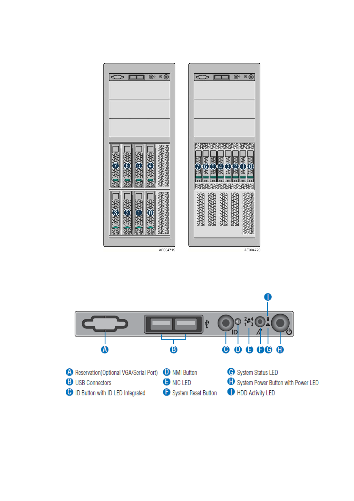
Hot Swap Hard Drive Bay and Front Panel Options
The figure below shows the 8x3.5” drive bay for Intel® Server System P4308CP4MHEN and
P4308CP4MHGC, and 8x2.5” drive bay for Intel
®
Server Board S2600CP Intel® Server System P4000CP Family Service Guide 3
Intel
®
Server System P4208CP4MHGC.
Page 18
Server System Features
Figure 4. Hot Swap Hard Drive Bay and Front Panel Options
Front Control Panel
Below figure show the layout of components on Front Control Panel.
Figure 5. Front Control Panel
4 Intel® Server Board S2600CP Intel® Server System P4000CP Family Service Guide
Page 19

Server System Features
Back Panel
The following figures show the layout of Back Panel with 550-W fixed power supply and 750-W
redundant power supplies.
A Power Supply F Serial-B Port (Optional)
B IO Connectors G Kensington* Cable Lock Mounting Hole
C RMM4 NIC Port (Optional) H Padlock Loop
D Add in PCI-e cards I RMM4 NIC Port (Optional)
E Power Connector
Figure 6. Back Panel With 550-W PSU
A
Power Supply
B Power Connector H Serial-B Port (Optional)
C Power Connector I Kensington* Cable Lock Mounting Hole
D Power Supply J Padlock Loop
E IO Connectors K RMM4 NIC Port (Optional)
F RMM4 NIC Port (Optional)
G
Add in PCI-e cards
Figure 7. Back Panel With 750-W PSU
®
Server Board S2600CP Intel® Server System P4000CP Family Service Guide 5
Intel
Page 20

Server System Features
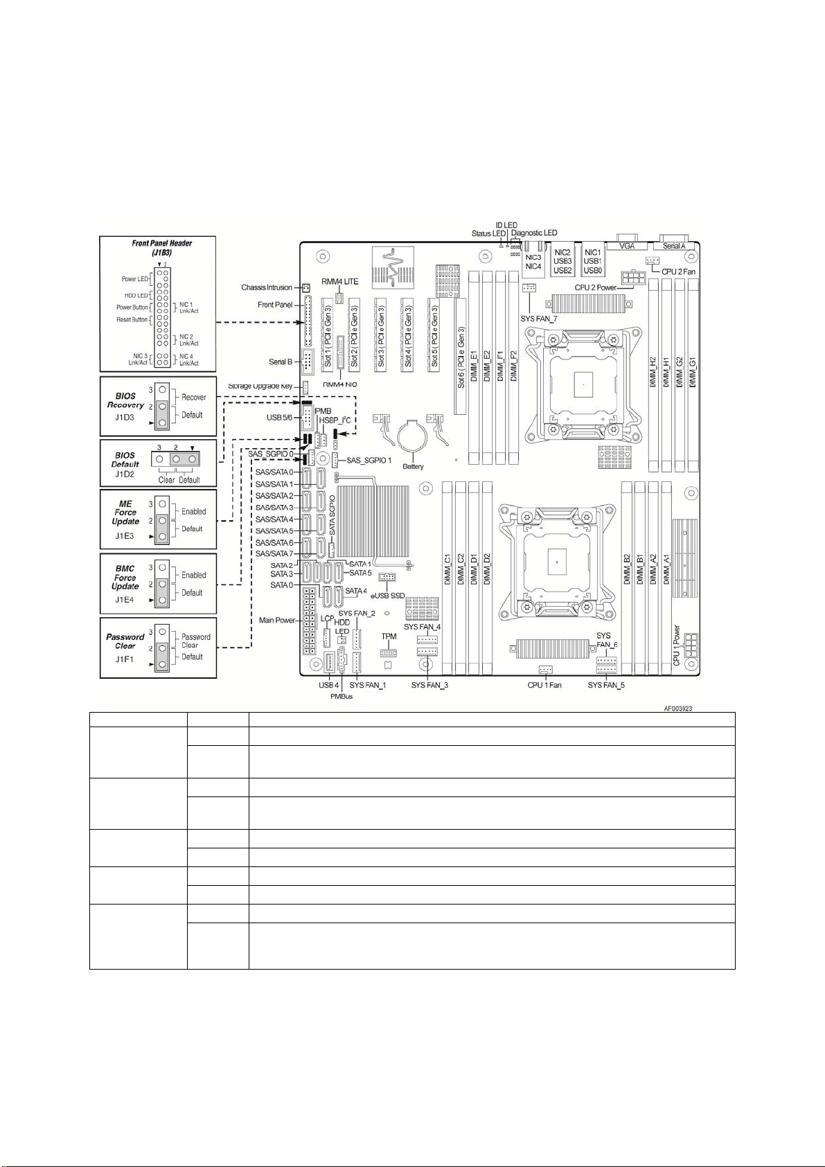
Server Board Components
This section helps you identify the components and co nnectors on the Intel® Server Board S2600CP.
Callout Description Callout Description
A Slot 1, PCI Express* Gen3 AC System Fan 4 connector
B RMM4 LITE AD Internal eUSB SSD
C RMM4 NIC AE TPM
D Slot 2, PCI Express* Gen3 AF System Fan 2
E Slot 3, PCI Express* Gen3, open-ended AG System Fan 1
F Slot 4, PCI Express* Gen3 AH PMBus
G Battery AI Type-A USB
H
6 Intel® Server Board S2600CP Intel® Server System P4000CP Family Service Guide
Slot 5, PCI Express* Gen3, from second processor,
open-ended
AJ LCP
Page 21

Server System Features
Callout Description Callout Description
I Slot 6, PCI Express* Gen3, support riser card AK HDD activity LED
J DIMM E1/E2/F1/F2 AL Main Power
K System Status LED AM SATA 3G connector
L ID LED AN SATA 6G connector
M Diagnostic LED AO SATA SGPIO
N NIC 3/4 (only on Quad NIC board) AP SATA/SAS connector
O USB 0/1/2/3, NIC 1,2 AQ SAS SGPIO 2
P VGA AR Password Clear
Q Serial Port A AS SAS SGPIO 1
R Processor 2 Fan connector AT IPMB
S Processor 2 Power connector AU ME Force Update
T System Fan 7 connector AV BMC Force Update
U DIMM H1/H2/G1/G2 AW HSBP_I2C
V Processor 1 Power connector AX USB to front panel
W DIMM A1/A2/B1/B2 AY BIOS Default
X System Fan 5 connector AZ Intel C600 RAID Upgrade key connector
Y System Fan 6 connector BA BIOS Recovery
Z Processor 1 Fan connector BB Serial B connector
AA DIMM C1/C2/D1/D2 BC
AB System Fan 3 connector BD Chassis Intrusion
SSI Front Panel (24-pin) and NIC 3/4
LED (4-pin)
Figure 8. Server Board Connector and Component Locations
Intel® Light-Guided Diagnostics
The figure in below shows the locations of Diagnostic LEDs on Intel® Server Board S2600CP.
®
Server Board S2600CP Intel® Server System P4000CP Family Service Guide 7
Intel
Page 22
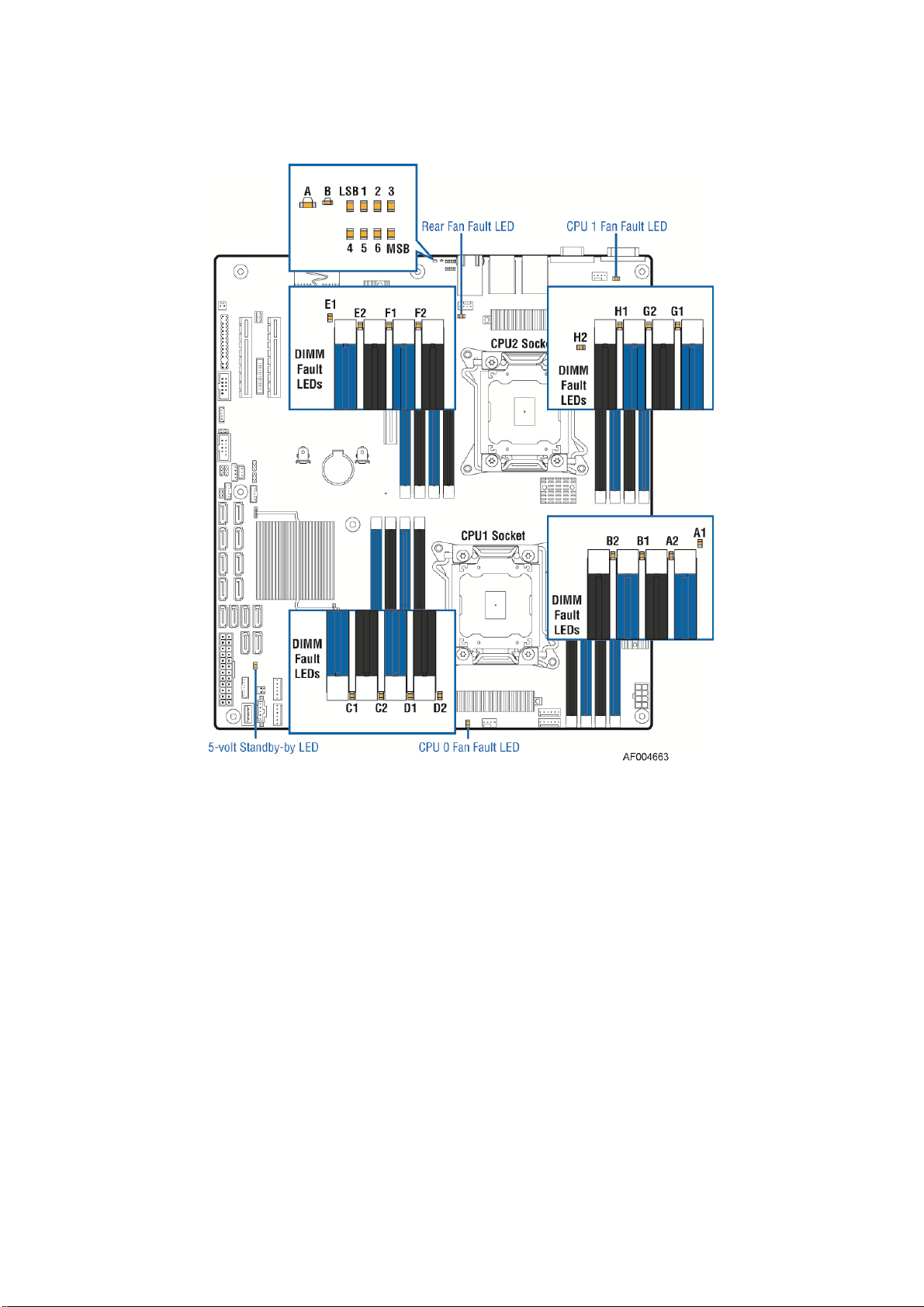
Server System Features
Figure 9. Intel® Light-Guided Diagnostic LEDs - Server Board
The server system contains the following diagnostic LEDs, each providing the following functions:
A - The System Status LED on the front and back panels shows the overall health of the system (green,
blinking green, blinking amber, amber, off).
B - The System Identification LED on the front and back panel helps identify the server from among
several servers. The ID LED is off by default, and blue when activated by button or software.
POST Code Diagnostic LEDs on the server board change color or state (off, green, red, amber) according
to the POST sequence.
The 5V-STBY LED on the server board is illuminated (green) when power is applied.
CPU fault LEDs help identify the failure of CPU. The CPU fault LEDs turn on (amber) if there is a CPU
fault.
DIMM Fault LEDs on the server board help identify failed and failing DIMM slots. The DIMM fault
LEDs turn on (amber) if there is a DIMM fault.
8 Intel® Server Board S2600CP Intel® Server System P4000CP Family Service Guide
Page 23
Server System Features
System Jumpers
The figure below shows the locations of System Jumpers on Intel® Server Board S2600CP.
Jumper Name Pins System Results
1-2 Pins 1-2 should be connected for normal system operation. (Default)
BIOS Recovery
BIOS Default
(a.k.a CMOS
Clear)
ME Force
Update
BMC Force
Update
Password Clear
2-3
1-2 These pins should have a jumper in place for normal system operation. (Default)
2-3
1-2 ME Firmware Force Update Mode – Disabled (Default)
2-3 ME Firmware Force Update Mode – Enabled
1-2 BMC Firmware Force Update Mode – Disabled (Default)
2-3 BMC Firmware Force Update Mode – Enabled
1-2 These pins should have a jumper in place for normal system operation. (Default)
2-3
The main system BIOS does not boot with pins 2-3 connected. The system only boots from EFIbootable recovery media with a recovery BIOS image present.
If pins 2-3 are connected when AC power unplugged, the CMOS settings clear in 5 seconds.
Pins 2-3 should not be connected for normal system operation.
To clear administrator and user passwords, power on the system with pins 2-3 connected. The
administrator and user passwords clear in 5-10 seconds after power on. Pins 2-3 should not be
connected for normal system operation.
Figure 10. Configuration Jumpers
®
Server Board S2600CP Intel® Server System P4000CP Family Service Guide 9
Intel
Page 24
Server System Features
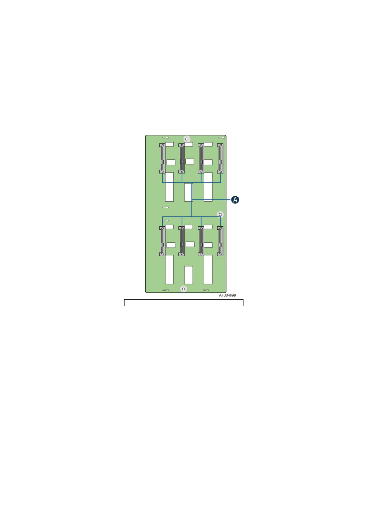
Hot-Swap SAS/SATA Backplane
The Hot-Swap SAS/SATA backplane serves as an interface between the mother board and the system
drives. The following diagrams show the location for each connector found on the backplane.
8 x 3.5-inch Hard Drive Backplane
A SAS/SATA Hot-swap Connectors
Figure 11. 8x3.5 backplane – Front View
10 Intel® Server Board S2600CP Intel® Server System P4000CP Family Service Guide
Page 25
Server System Features
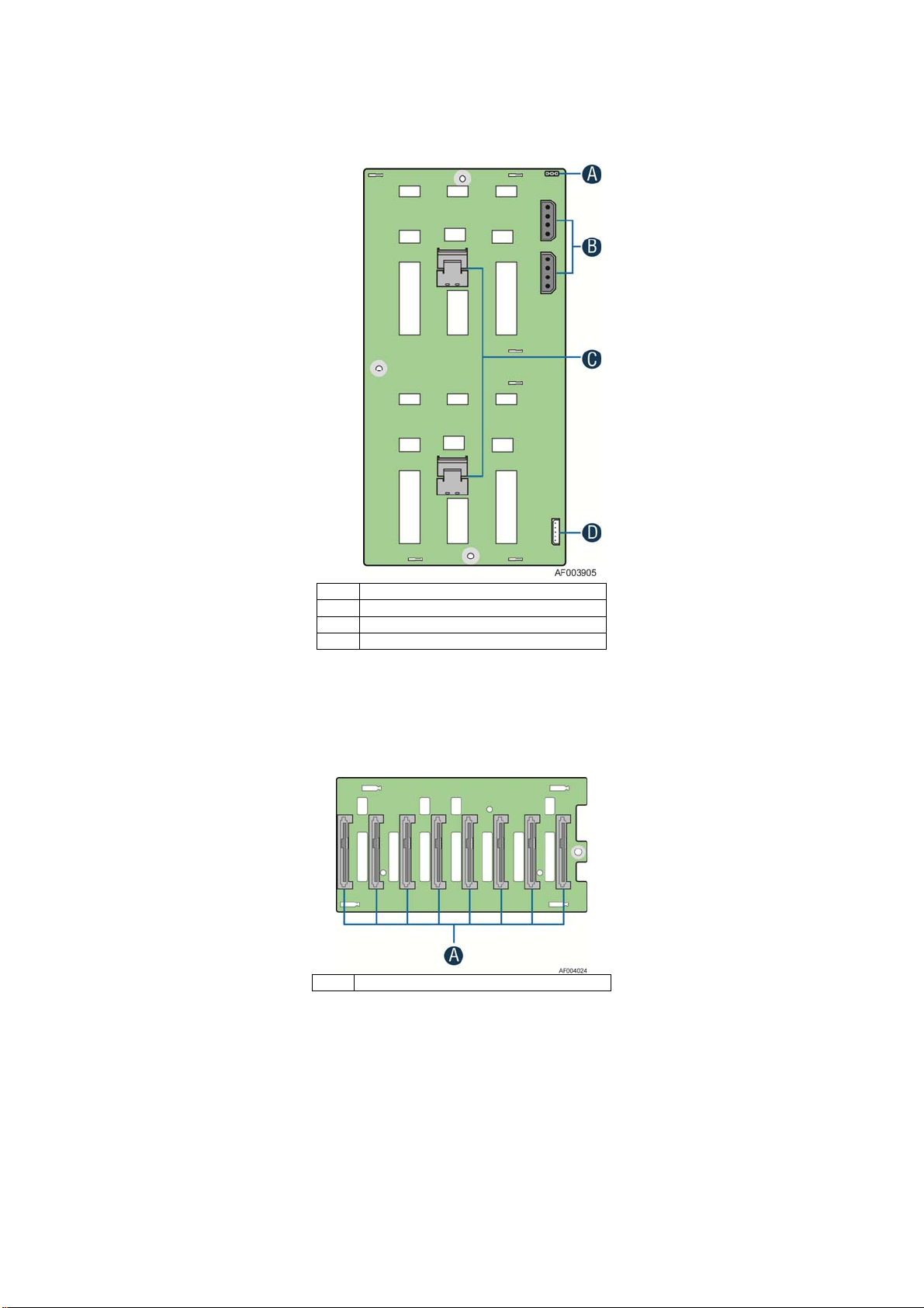
A Reserved
B Power Connector
C Mini-SAS Connectors
D I2C In Connector
Figure 12. 8x3.5 backplane – Rear View
8 x 2.5-inch Hard Drive Backplane
A SAS/SATA Hot-swap Connectors
Figure 13. 8 x 2.5 backplane - Front View
®
Server Board S2600CP Intel® Server System P4000CP Family Service Guide 11
Intel
Page 26
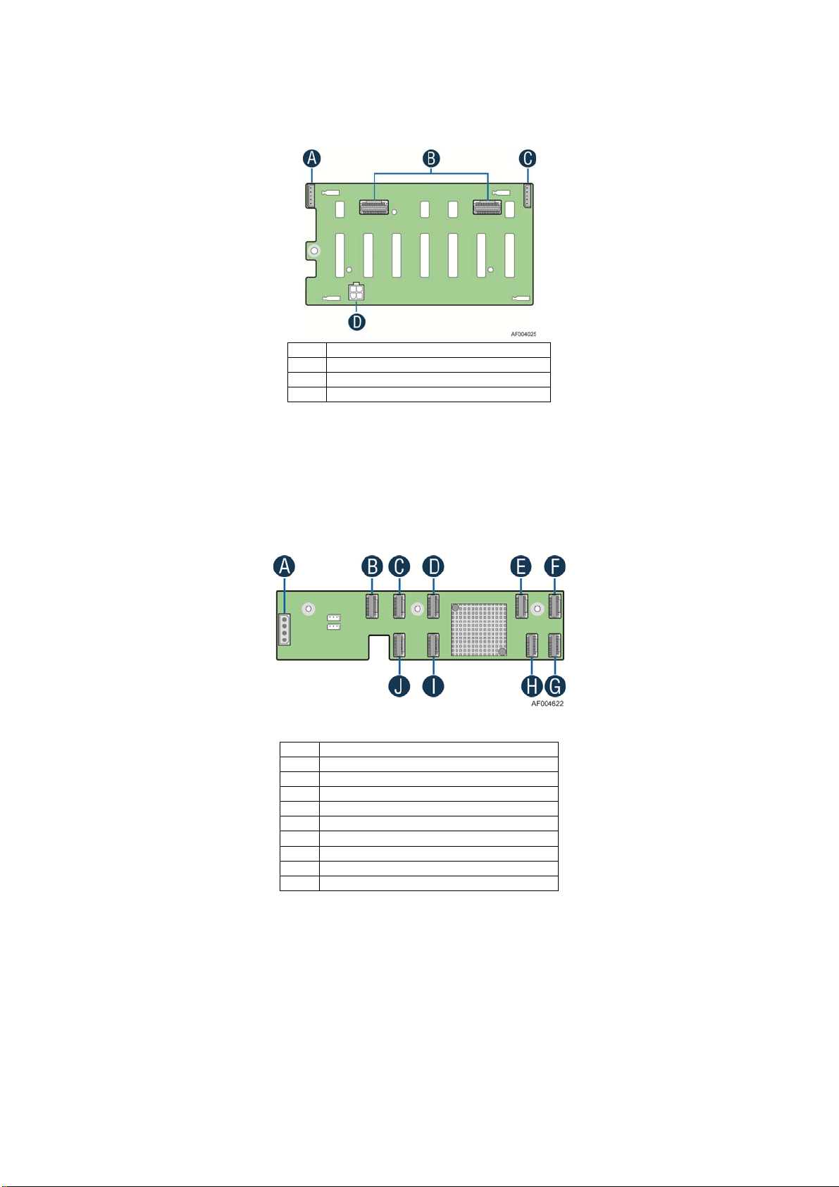
Server System Features
A I2C Out Connector
B Mini-SAS Connectors
C I2C In Connector
D Power Connector
Figure 14. 8 x 2.5 backplane - Rear View
Intel® RAID Expander Cards (Upgrade Option)
Intel provides two types of internal RAID expander cards: 36 ports and 24 ports.
A Power Connector
B Mini-SAS Connector A
C Mini-SAS Connector B
D Mini-SAS Connector G (36 port sku only)
E Mini-SAS Connector H (36 port sku only)
F Mini-SAS Connector I (36 port sku only)
G Mini-SAS Connector F
H Mini-SAS Connector E
I Mini-SAS Connector D
J Mini-SAS Connector C
Figure 15. Internal Intel® RAID Expander Cards Components
12 Intel® Server Board S2600CP Intel® Server System P4000CP Family Service Guide
Page 27

Advanced Management Options
®
Remote Management Module 4
Intel
The Intel® Remote Management Module 4 plugs into a dedicated connector on the server board
and provides additional server management functionality to the server board.
This module provides a dedicated web server for viewing server information and remote control of
the system. It also provides Remote KVM Redirection and USB Media Redirection allowing USB
devices attached to the remote system to be used on the managed server.
For instructions on installing the Intel
Removing the Intel
®
Remote Management Module 4”.
®
Remote Management Module 4, see “Installing and
Server System Features
®
Server Board S2600CP Intel® Server System P4000CP Family Service Guide 13
Intel
Page 28

Hardware Installations and Upgrades
2 Hardware Installations and Upgrades
Before You Begin
Before working with your server product, pay close attention to the “Safety Information” at the
beginning of this manual.
NOTE
/
Whenever you service the system, you must first power down the server and unplug all
peripheral devices and the power cord.
Tools and Supplies Needed
Phillips* (cross head) screwdriver (#1 bit and #2 bit)
Needle nosed pliers
Anti-static wrist strap and conductive foam pad (recommended)
System Reference
All references to left, right, front, top, and bottom assume the reader is facing the front of the
chassis as it would be positioned for normal operation.
14 Intel
®
Server Board S2600CP Intel® Server System P4000CP Family Service Guide
Page 29
Hardware Installations and Upgrades
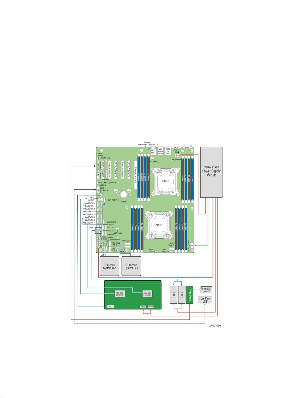
Cable Routing Recommendations
When you add or remove components from your server system, make sure your cables are routed
correctly before reinstalling the server system cover. Use caution to make sure no cables or wires are
pinched and that the airflow from the fans is not blocked. Use the figures below to deter mine the correct
cable routing.
NOTE:
/
To activate the port SATA/SAS 4-7 on the server board, a proper Intel® RAID C600 Upgrade Key
must be installed. For instructions, see Intel
Cable connections for Intel
®
Server System P4308CP4MHEN:
®
RAID C600 Upgrade Key Installation Guide.
Figure 16. Cable connections for Intel® Server System P4308CP4MHEN
®
Server Board S2600CP Intel® Server System P4000CP Family Service Guide (Preliminary) 15
Intel
Page 30
Hardware Installations and Upgrades
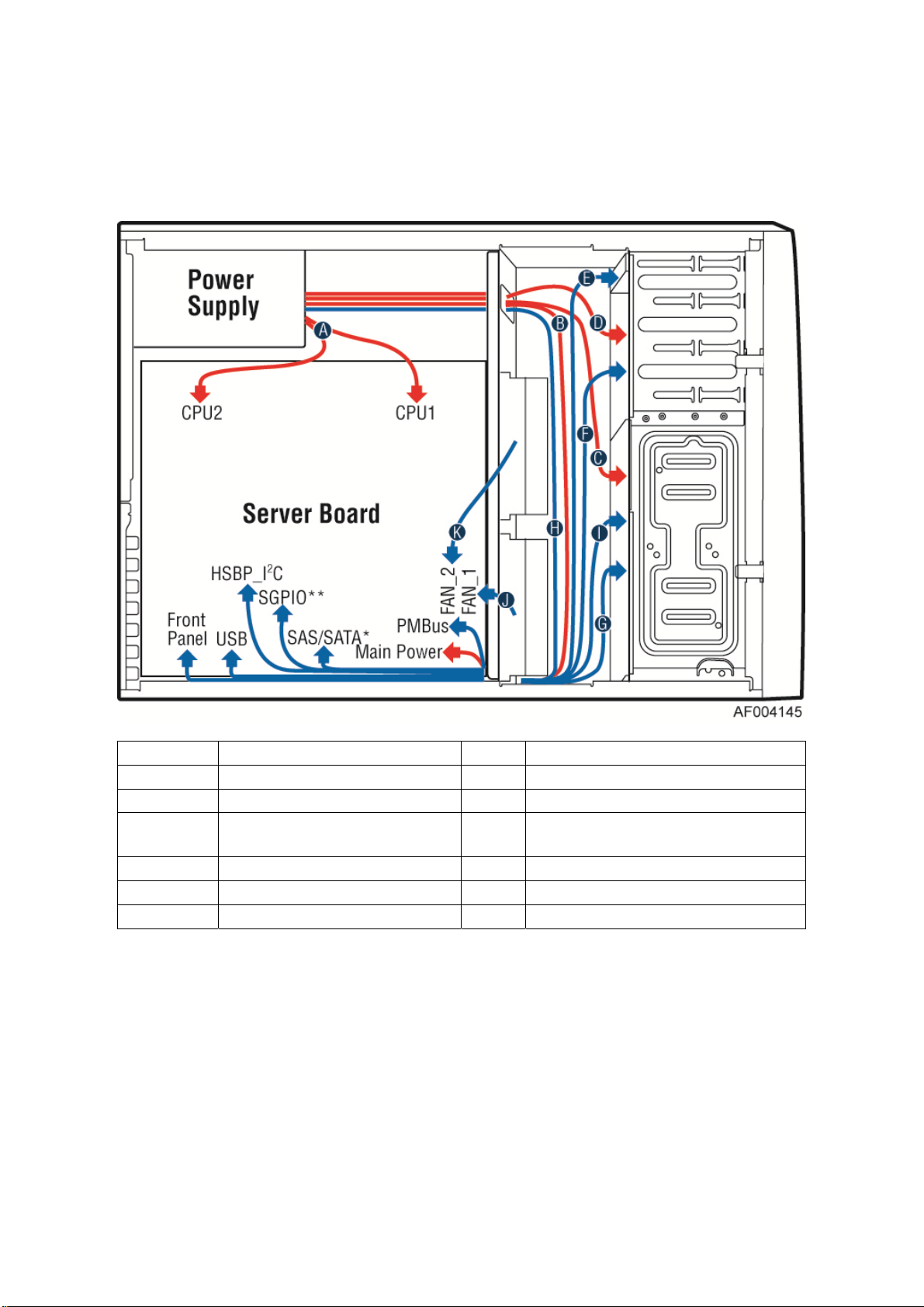
Cable routing for Intel
®
Server System P4308CP4MHEN:
Callout
A CPU1/CPU2 Power Cable B Server Board Main Power Cable
C Hot-swap Backplane Power Cable D ODD Power Cable
E Front Panel Cable, USB Cable F
G MiniSAS and SGPIO Cable H PMBus
I Hot-swap Backplane I2C Cable J System Fan 1 Cable
K System Fan 2 Cable
Description Callout Description
ODD Data Cable (Connect To White SATA 6G
Connectors On Server Board)
Figure 17. Cable routing for Intel® Server System P4308CP4MHEN
16 Intel
®
Server Board S2600CP Intel® Server System P4000CP Family Service Guide
Page 31

Cable connections for Intel
Hardware Installations and Upgrades
®
Server System P4308CP4MHGC and P4208CP4MHGC:
Figure 18. Cable connections for Intel® Server System P4308CP4MHGC and P4208CP4MHGC
®
Server Board S2600CP Intel® Server System P4000CP Family Service Guide (Preliminary) 17
Intel
Page 32

Hardware Installations and Upgrades
Cable routing for Intel
®
Server System P4308CP4MHGC and P4208CP4MHGC:
Callout
A CPU1/CPU2 Power Cable B Server Board Main Power Cable
C Hot-swap Backplane Power Cable D ODD Power Cable
E Front Panel Cable, USB Cable F
G MiniSAS and SGPIO H PMBus Cable
I Hot-swap Backplane I2C Cable J System FAN 1
K System FAN 2 L System FAN 3
M System FAN 4 N System FAN5
Description Callout Description
ODD Data Cable (Connect To White SATA 6G
Connectors on Server Board)
Figure 19. Cable routing for Intel® Server System P4308CP4MHGC and P4208CP4MHGC
18 Intel
®
Server Board S2600CP Intel® Server System P4000CP Family Service Guide
Page 33

Hardware Installations and Upgrades
Removing and Installing the System Side Cover
Remvoing the System Side Cover
The Intel® Server System P4000CP family must be operated with the top cover in place to
ensure proper cooling. You will need to remove the top cover to add o r replace components
inside of the platform. Before removing the top cover, power down the server and unplug all
peripheral devices and the AC power cable.
NOTE
/
A non-skid surface or a stop behind the chassis may be needed to prevent the chassis from
slding on your work surface.
1. Observe the safety and ESD precautions at the beginning of this book.
2. Turn off all peripheral dev ices connected to the server. Turn off the server.
3. Disconnect the AC power cord.
4. Remove the screws (see letter "A").
5. Slide the side cover back (see letter "B") and lift the cover outward to remove it.
Figure 20. Removing the Side Cover
®
Server Board S2600CP Intel® Server System P4000CP Family Service Guide (Preliminary) 19
Intel
Page 34

Hardware Installations and Upgrades
Installing the System Side Cover
1. Slide the chassis cover on the chassis (see letter “A”).
2. Latch the cover securely to the chassis.
3. Secure the chassis cover with the screws (see letter “B”).
Figure 21. Installing the Side Cover
Removing and Installing the Front Bezel
Remvoing the Front Bezel
NOTE
/
For a rack configuration or chassis on its side, position the chassis hanging over the edge of a
table or workbench before removing the bezel.
There are two type of bezel assembly. One type is for fixed HDD configuration, the other type is
for Hot-swap HDD configuration.
CAUTION
Do not rotate the bezel assembly more than 40 degrees or you will damage the bezel
assembly.
1. Observe the safety and ESD precautions at the beginning of this book.
2. Power down the server and unplug all peripheral devices and the AC power cable.
3. Remove the chassis cover. For instructio ns, see “Removing the System Side Cover”.
4. Release the two plastic tabs on the left side of the bezel assembly to disengage the tabs, and
rotate the bezel assembly (see letter “A”) no more than 40 degrees outward.
5. At a 40-degree angle, push the bezel assembly away from the chassis (see letter “B”).
20 Intel
®
Server Board S2600CP Intel® Server System P4000CP Family Service Guide
Page 35

Hardware Installations and Upgrades
6. If the bezel assembly does not immediately disconnect from the chassis, tap the left-hand
side of the bezel assembly to disengage the bezel hooks on the right-hand side of the
chassis.
Figure 22. Removing the Front Bezel
Installing the Front Bezel
1. Fit the right edg e of the bezel assembly against the right side of the chassis.
2. Engage the plastic bezel hooks (see letter “A”) into the raised metal slots at the chassis
edge.
3. Rotate the bezel assembly tow ard the chassis.
4. Latch the two plastic tabs (see letter “B”) on the left side of the bezel assembly to the
chassis.
Figure 23. Installing the Front Bezel
®
Server Board S2600CP Intel® Server System P4000CP Family Service Guide (Preliminary) 21
Intel
Page 36

Hardware Installations and Upgrades
Removing and/or Installing Airduct
Always operate your server system with the air duct in place. The air duct is required for proper airflow
within the server system.
Removing the Airduct
1. Observe the safety and ESD precautions at the beginning of this book.
2. Power down the server and unplug all peripheral devices and the AC power cable.
3. Remove the chassis cover. For instruct io ns, see “R emo ving the Chassis Cover”.
4. Remove the airduct by gentlely by lifting the airduct out of chassis.
Installing the Airduct
1. Observe the safety and ESD precautions at the beginning of this book.
2. Power down the server and unplug all peripheral devices and the AC power cable.
3. Remove the chassis cover. For instructions, see “Removing the Chassis Cover”.
4. Install the airduct by matching the alignment tabs on airduc t and th e align men t ho les on
chassis bracket.
®
22 Intel
Server Board S2600CP Intel® Server System P4000CP Family Service Guide
Figure 24. Removing the Airduct
Page 37

Hardware Installations and Upgrades
Figure 25. Installing the Airduct
Removing and Installing Processor
The heatsink has thermal interface material (TIM) on the underside of it. Use caution so that you do
not damage the thermal interface material. Use gloves to avoid sharp edges.
Removing Processor Heatsink(s)
The heatsink is attached to the server board/processor socket with captive fasteners. Using a #2
Phillips* screwdriver, loosen the four screws located on the heatsink corners in a diagonal manner
using the following procedure:
1. Using a #2 Phillips* screwdriver, start with screw 1 and loosen it by giving it two rotations
and stop (see letter “A”). (IMPORTANT: Do not fully loosen.)
2. Proceed to screw 2 and loosen it by giving it two rotations and stop (see letter “B”).
Similarly, loosen screws 3 and 4. Repeat steps A and B by giving each screw two rotations
each time until all screws are loosened.
3. Lift the heatsink straight up (see letter “C”).
®
Server Board S2600CP Intel® Server System P4000CP Family Service Guide (Preliminary) 23
Intel
Page 38

Hardware Installations and Upgrades
Installing the Processor
Figure 26. Removing Processor Heatsink
Caution: Processor must be appropriate: You may damage the server board if you install a
processor that is inappropriate for your server. For a web link to the list of compatible processor(s),
see “Additional Information and Software”.
Caution: ESD and handling processors: Reduce the risk of electrostatic discharge (ESD) damage
to the processor by doing the following: (1) Touch the metal chassis before touching the processor
or server board. Keep part of your body in contact with the metal chassis to dissipate the static
charge while handling the processor. (2) Avoid moving around unnecessarily.
Caution: Protective socket cover needs to be removed for proper cooling of the processor; failure
to remove the cover could result in damage to the system.
1. Open the Sock et Lever. Push down the lever handle on the OPEN 1st side and away from the
socket to release it (see letter “A”). Repeat the steps to release the lever on the other side (see
letter “B”).
Figure 27. Installing Processor – Open the Socket Lever
2. Open the Load Pla te. Press the locking lever slightly to raise the load plate (see letter “A”).
Open the load plate all the way (see letter “B”).
24 Intel
®
Server Board S2600CP Intel® Server System P4000CP Family Service Guide
Page 39

Hardware Installations and Upgrades
Figure 28. Installing Processor – Open the Load Plate
3. Install the Processor. Take the p rocessor out of the box and remove the protective shipping
cover (see letter “A”). Orient the processor with the socket so that the processor cutouts match
the four orientation posts on the socket (see letter “B”). Note location of gold key at corner of
processor (see letter “C”).
Figure 29. Installing Processor – Install the Processor
NOTE
/
The underside of the processor has components that may damage the socket pins if
installed improperly. Processor must align correctly with the socket opening before
installation. DO NOT DROP processor int o socket!
4. Remove the Cover. Press the cover to remove it. Save the protective cover.
Figure 30. Installing Processor – Remove the Cover
5. Close the Load Plate. Carefully lower the load plate over the processor.
®
Server Board S2600CP Intel® Server System P4000CP Family Service Guide (Preliminary) 25
Intel
Page 40

Hardware Installations and Upgrades
Figure 31. Installing Processor – Close the Load Plate
6. Latch the Locking Lever. Push down on the locking lever on the CLOSE 1st side (see letter
“A”). Slide the tip of the lever under the notch in the load plate (see letter “B”). Make sure th e
load plate tab engages under the socket lever when fully closed. Repeat the steps to latch the
locking lever on the other side (see letter “C”). Latch the levers in the order as shown.
Figure 32. Installing Processor – Latch the Locking Lever
Installing Processor Heatsink(s)
1. Remove the protective film on the TIM if present.
2. Align heatsin k fins to the front and back of the chassis for correct airflow (see letter “A”).
Airflow goes from front-to-back of chassis.
Each heatsink has four captive fasteners and should be tightened in a diagonal manner using the
following procedure:
3. Using a #2 Phillips* screwdriver, start with screw 1 and engage screw threads by giving it two
rotations and stop (see letter “B”). (Do not fully tighten.)
4. Proceed to screw 2 and engage screw threads by giving it two rotations and stop. Similarly,
engage screws 3 and 4 (see letter “C”).
5. Repeat these steps on each screw with two rotations each time until each screw is lightly
tightened up to a maximum of 8 inch-lbs torque.
26 Intel
®
Server Board S2600CP Intel® Server System P4000CP Family Service Guide
Page 41

Figure 33. Installing Processor Heatsink
Installing and Removing Memory
Hardware Installations and Upgrades
Installing Memory
1. Locate the DIMM sockets. Make sure the clips at ei ther end o f the DIMM socket(s) are pushed
outward to the open position (see letter “A”).
2. Holding the DIMM by the edges, remove it from its anti-static package. Position the DIMM
above the socket. Align the notch on the bottom edge of the DIMM with the key in the DIMM
socket (see letter “B”).
3. Insert the bottom edge of the DIMM into the socket (see letter “C”). When the DIMM is
inserted, push down on the top edge of the DIMM until the retaining clips snap into place (see
letter “D”). Make sure the clips are firmly in place (see letter “E”).
Figure 34. Installing Memory
®
Server Board S2600CP Intel® Server System P4000CP Family Service Guide (Preliminary) 27
Intel
Page 42

Hardware Installations and Upgrades
Removing Memory
1. Locate the DIMM sockets. Gently spread the retaining clips at each end of the socket. The
DIMM lifts from the socket.
2. Holding the DIMM by the edges, lift it from the socket, and store it in an anti-static package.
Installing and Removing Hot-swap Hard Drive
Caution: If you don't install all drives, empty drive bays must be occupied by carriers with plastic
drive blank provided to maintain proper system cooling.
Installing a Hard Disk Drive into 3.5” Hard Drive Carrier
1. Remove the drive carrier by pressing the green button and opening the lever (see letter “A”).
Slide the carrier out (see letter “B”).
Figure 35. Installing Hard Disk Drive – Removing 3.5” HDD carrier
2. Remove the fo ur screws securing the HDD interface bracket and remove the HDD interface
bracket (see letter “C”).
Figure 36. Installing Hard Disk Drive – Removing 3.5” HDD interface bracket
3. Install the hard disk drive using the same four screws as shown. Make sure the connector end of
the drive matches the backplane connector (see letter “D”).
®
28 Intel
Server Board S2600CP Intel® Server System P4000CP Family Service Guide
Page 43

Hardware Installations and Upgrades
Figure 37. Installing Hard Disk Drive – Installing 3.5” HDD
For installing 2.5” Hard Disk Drive as option:
Break off the tab on the HDD interface bracket (see letter “d1”).Install the HDD interface
bracket from top. Secure the bracket with three screws as shown (see letter “d2”). Slide the 2.5"
HDD into the bracket to align the screw holes with the right and left rail (see letter “d3”). Secure
the hard disk drive using the four screws for 2.5" HDD (see letter “d4”).
Figure 38. Installing Hard Disk Drive – Installing 2.5” HDD
4. With the lever open, insert the hard disk drive assembly into the chassis (see letter “A”). Push
in the lever to lock it into place (see letter “B”).
Figure 39. Installing Hard Disk Drive – Inserting 3.5” HDD assembly
®
Server Board S2600CP Intel® Server System P4000CP Family Service Guide (Preliminary) 29
Intel
Page 44

Hardware Installations and Upgrades
Installing a Hard Disk Drive into 2.5” Hard Drive Carrier
1. Remove the drive carrier by pressing the green latch to unlock (see letter “A”). Pull out the
black lever and slide the carrier out (see letter “B”).
Figure 40. Installing Hard Disk Drive – Removing 2.5” HDD carrier
2. Remove the fo ur screws securing the plastic drive blank from the 2.5" HDD carrier (see letter
“C”). Disengage the plastic drive blank from the HDD carrier. Remove the plastic drive blank
from the 2.5" HDD carrier (see letter “D”).
Figure 41. Installing Hard Disk Drive – Removing plastic drive blank
3. Install the hard disk d rive using the four screws as shown. Make Sure the connector end of the
drive matches the backplane connector (see letter “E”).
Figure 42. Installing Hard Disk Drive – Installing 2.5” HDD
4. With the lever open, insert the hard disk drive assembly into the chassis (see letter “G”), then
push in the lever to lock it into place (see letter “H”).
®
30 Intel
Server Board S2600CP Intel® Server System P4000CP Family Service Guide
Page 45

Hardware Installations and Upgrades
Figure 43. Installing Hard Disk Drive – Inserting 2.5” HDD assembly
Installing and Removing a PCI Add-in Card
Installing a PCI Add-in Card
1. Observ e the safe ty and ESD precautions at the beginning of this book.
2. Power down the server and unp lug all peripheral devices and the AC pow er cable.
3. Remove the chassis cover. For instructions, see “Removing the Chassis Cover”.
4. Remove the aird uct by gentlely lifting the airduct out of chassis.
5. Remove the PCI slot sh ield from the chassis rear end. See letter A.
Figure 44. Remove PCI slot shield
6. Open the PCI card retainer. See letter B.
®
Server Board S2600CP Intel® Server System P4000CP Family Service Guide (Preliminary) 31
Intel
Page 46

Hardware Installations and Upgrades
Figure 45. Open PCI card retainer
7. Open the PCI card retention device. See letter C.
Figure 46. Open PCI card retention device
8. Align the PCI card and insert into place. See letter D.
Figure 47. Install PCI card
®
32 Intel
Server Board S2600CP Intel® Server System P4000CP Family Service Guide
Page 47

Hardware Installations and Upgrades
9. Close the PCI card retention device. See letter E. Recommend to secure the PCI card with a
screw.
Figure 48. Close PCI card retention device
10. Close the PCI retainer and secure the PCI card.
Figure 49. Close PCI card retainer.
Removing a PCI Add-in Card
1. Observ e the safe ty and ESD precautions at the beginning of this book.
2. Power down the server and unp lug all peripheral devices and the AC pow er cable.
3. Remove the chassis cover. For instructions, see “Removing the Chassis Cover”.
4. Remove the aird uct by gentlely lifting the airduct out of chassis.
5. Open the PCI card retainer.
6. Release PCI card retention d evice, remove screw if there is.
®
Server Board S2600CP Intel® Server System P4000CP Family Service Guide (Preliminary) 33
Intel
Page 48

Hardware Installations and Upgrades
7. Gentlely lift the PCI car d from PCI slot.
8. Install a PCI slot shielter. Restore the PCI card retention device and PCI card retainer back to
orginal position.
Design A GPGPU Card Extender
A GPGPU card bracket can help better secure a heavy GPGPU card, the bracket can be installed on
position as shown by below figure.
Figure 50. Installing the GPGPU Card Fixture
Users need to design a GPGPU card extender to make a non-full length GPGPU card to be full length, in
order to take advandage of the GPGPU card bracket.
Figure 51. Secure the GPGPU card with GPGPU bracket
34 Intel
®
Server Board S2600CP Intel® Server System P4000CP Family Service Guide
Page 49

The following figures show an example of the GPGPU bracket:
Figure 52. Side View of a GPGPU Card Extender Example
Hardware Installations and Upgrades
Figure 53. Top View of a GPGPU Card Extender Example
Installing and Removing an Optical Drive
Cautions: Before removing or replacing the drive, you must first take the server out of servic e, turn
off all peripheral devices connected to the system, turn off the system by pressing the power button,
and unplug the power cord from the system or wall outlet.
To maintain proper system cooling, a filler panel must be installed if you do not install a device at
this location.
Installing an Optical Drive
1. Remove the O filler (see letter “A”).
®
Server Board S2600CP Intel® Server System P4000CP Family Service Guide (Preliminary) 35
Intel
Page 50

Hardware Installations and Upgrades
Figure 54. Remove the Optical Drive filler
2. Get the two optical drive rails from chassis side (see letter “B”) and affix them to both optical
drive sides, make sure the pinches on the optical drive rail are aligned with the alignment holes
on the ODD (see letter “C”). Insert the optical drive into chassis opening and push all the way
until it stops (see letter “D”). Connect the power and data cables to optical drive.
Figure 55. Installing an Optical Drive
Removing an Optical Drive
1. Remove the cables from optic al drive.
2. Press the latc hing end of optical drive rails (see letter “A”) and pull the optical drive out (see
letter “B”).
3. Remvoe the optical drive rail from the drive (see letter “C”).
Figure 56. Remove an Optical Drive
36 Intel
®
Server Board S2600CP Intel® Server System P4000CP Family Service Guide
Page 51

Hardware Installations and Upgrades
4. Install the optical drive filler.
Figure 57. Install optical drive filler.
Installing and Removing the Intel® RAID C600 Upgrade
Key
Installing the Intel® RAID C600 Upgrade Key
Locate the white 4-pin key header. Carefully pickup the Intel® RAID C600 Upgrade Key. Match
the Key and connector orientation and press down to install.
Figure 58. Installing the Intel® RAID C600 Upgrade Key
Removing the Intel® RAID C600 Upgrade Key
Pull up the key to remove it from the mother board.
®
Server Board S2600CP Intel® Server System P4000CP Family Service Guide (Preliminary) 37
Intel
Page 52

Hardware Installations and Upgrades
Figure 59. Removing the Intel® RAID C600 Upgrade Key
Installing and Removing the Intel® Remote Management
Module 4
Installing the Intel® RMM4 Lite
Locate the RMM4 Lite connector next to RISER SLOT_1, carefully pickup the Intel® RMM4 Lite
module, match the alignment pin of the module and the connector on server board, then press to
install.
Figure 60. Installing the Intel® RMM4 Lite
Install the Intel® RMM4 NIC
1. Push out and remove the metal cover o n the chassis where the NIC RJ-4 5 receptacle will align
(see letter “B”).
2. Connect the cable to the module (see letter “C”).
3. Secure the mod ule to the cahsssi with the two screws (see letter “D”).
®
38 Intel
Server Board S2600CP Intel® Server System P4000CP Family Service Guide
Page 53
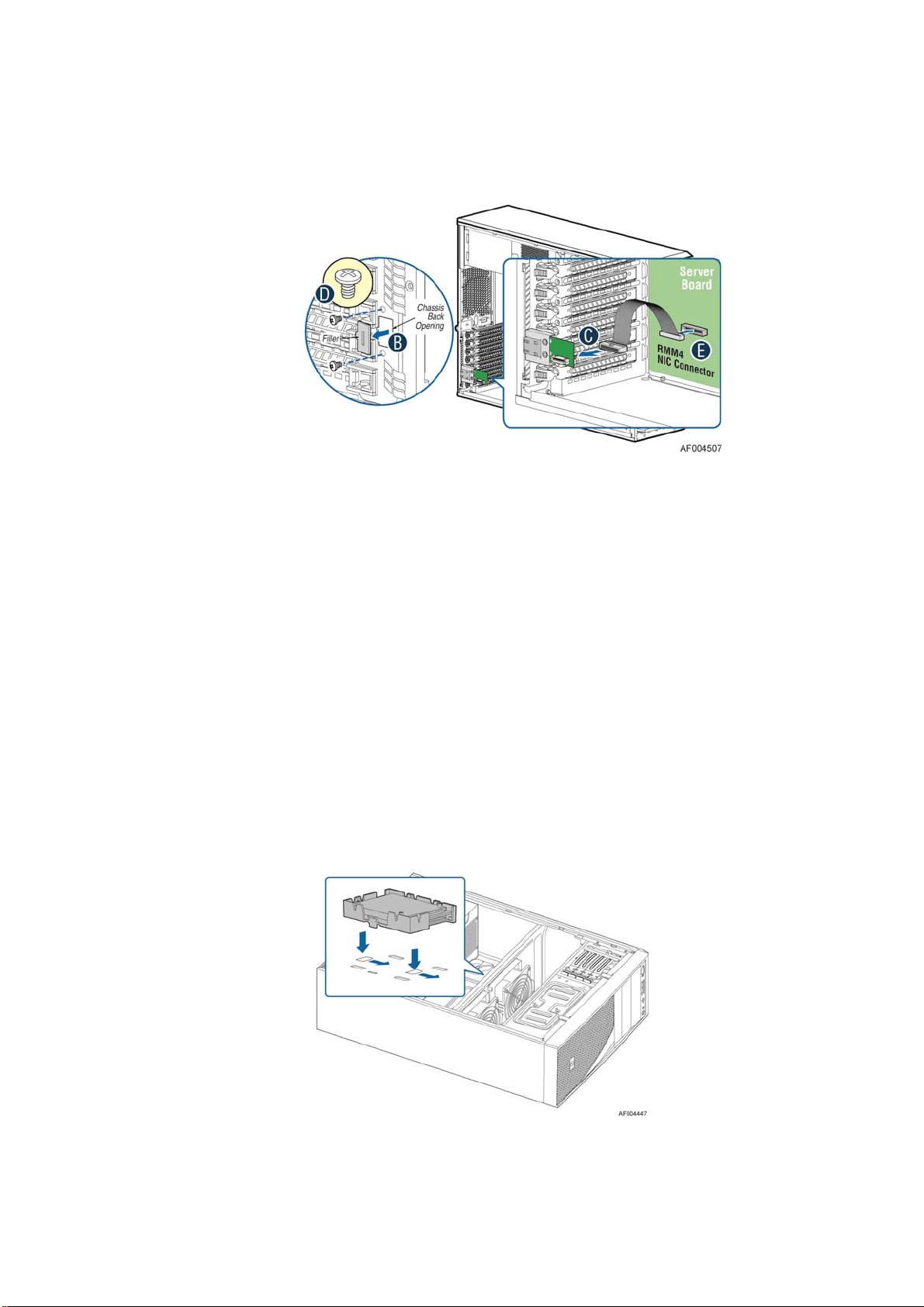
4. Connect the cable to the server board connector (see letter “E”).
Figure 61. Installing the Intel® RMM4 NIC
Removing the Intel® RMM4 Lite
Pull up the RMM4 Lite module to remove it from the mother board.
Hardware Installations and Upgrades
Removing the Intel® RMM4 NIC
1. Unp lug the cable from module and server board.
2. Remove the screws and remove the module from the server chassis.
Installing and Removing the Intel® RAID Smart Battery
Installing the Intel® RAID Smart Battery
1. Connect the cable between the BBU and the RAID card. For details, see Intel® RAID Smart
Battery User’s Guide.
2. Locate the mounting holes inside the chassis.
3. Align the tabs on the plastic battery holder with the mounting holes in the chassis and slide the
plastic battery holder until the tabs engage with the mounting holes.
®
Server Board S2600CP Intel® Server System P4000CP Family Service Guide (Preliminary) 39
Intel
Page 54

Hardware Installations and Upgrades
Figure 62. Installing the Intel® RAID Smart Battery
Removing the Intel® RAID Smart Battery
1. Pull the tab until the tab is disengaged from the chassis cut.
2. Slide the battery from the server chassis side wall and move it out of the opening in the fan
bulkhead.
3. Lift the battery up to remove it from the server chassis.
Figure 63. Removing the Intel® RAID Smart Battery
Removing and Installing the Fixed Power Supply
WARNING
Hazardous voltage, current, and energy levels are present inside the power supply.
There are no user-serviceable parts inside it; servicing should be done by technically
qualified personnel.
Removing the Fixed Power Supply
1. Observe the safety and ESD precautions at the beginning of this book.
2. Power down the server and unplug all peripheral devices and the AC power cable.
3. Remove the chassis cover. For instruct io ns, see “R emo ving the Chassis Cover”.
4. Remove the air duct if it is installed. For instructions, see “Installing the Airduct”.
5. Disconnec t all interna l power cables from chassis components and server board.
6. Rotate the power supp ly locking device counter-clock w ise (see letter “A”) and remove the
fixed power supply (see letter “B”).
40 Intel
®
Server Board S2600CP Intel® Server System P4000CP Family Service Guide
Page 55

Figure 64. Removing Fixed Power Supply
Installing the Fixed Power Supply
Hardware Installations and Upgrades
1. Insert new fixed po wer supply and rotate the power supply locking device clockwise (see
letter “A” and “B”).
Figure 65. Installing Fixed Power Supply
2. Reconnect pow er cables to other chassis components as appropriate.
3. Install the air duct. For instructions, see “Installing the Airduct”.
4. Install the chassis cov er. For instructions, see “Installing the Chassis Cover”.
5. Plug all peripheral dev ic es and the AC power cable into the server.
6. Power up the server.
®
Server Board S2600CP Intel® Server System P4000CP Family Service Guide (Preliminary) 41
Intel
Page 56

Hardware Installations and Upgrades
Installing an Additional Hot-swap Power Supply
Module
WARNING
Hazardous voltage, current, and energy levels are present inside the power supply.
There are no user-serviceable parts inside it; servicing should be done by technically
qualified personnel.
1. Observe the safety and ESD precautions at the beginning of this book.
2. Insert finger into fing er hole in middle of filler pane l and remove the filler panel from
chassis.
Figure 66. Removing Power Supply Filler Panel
3. Insert the power supply module into the power supply cage and push all the way until it
clicks into place.
Figure 67. Installing Additional Hot-swap Power Supply Module
Replacing a Hot Swap Power Supply Module
WARNING
Hazardous voltage, current, and energy levels are present inside the power supply.
There are no user-serviceable parts inside it; servicing should be done by technically
qualified personnel.
1. Observ e the safe ty and ESD precautions at the beginning of this book.
2. Remove power cable fro m defective po wer supply.
3. Press up on green latch in the direction shown while pulling on handle to remove hot swap
power supply from chassis.
®
42 Intel
Server Board S2600CP Intel® Server System P4000CP Family Service Guide
Page 57

Hardware Installations and Upgrades
Figure 68. Removing Hot-swap Power Supply Module from Chassis
4. Insert new power supply modu le into the pow er supply cage and push all the way until it clicks
into place.
Figure 69. Installing Hot-swap Power Supply Module into Chassis
Replacing the Power Distribution Board
WARNING
Hazardous voltage, current, and energy levels are present inside the power supply.
There are no user-serviceable parts inside it; servicing should be done by technically
qualified personnel.
1. Observe the safety and ESD precautions at the beginning of this book.
2. Power down the server and unplug all peripheral devices and the AC power cable.
3. Remove the chassis cover. For instruct io ns, see “R emo ving the Chassis Cover”.
4. Remove the air duct. For instructions, see “Installing the Aird uct”.
5. Disconnec t all interna l power cables from chassis components and server board.
6. If present, press on green latch in the direction shown while pulling on handle to remove
power supply from chassis. Repeat this step for the second hot-swap power supply if it is
installed.
®
Server Board S2600CP Intel® Server System P4000CP Family Service Guide (Preliminary) 43
Intel
Page 58

Hardware Installations and Upgrades
Figure 70. Removing Hot-swap Power Supply Module from Chassis
7. Loosen screws securing the b racket with po wer distribution board to the chassis (see letter
“A” and “B”).
Figure 71. Loosing the Bracket with Power Distribution Board from Chassis
8. Push the bracket forward to release the latch which secure the bracket then pull out the
bracket from the chassis (see letter “C”).
44 Intel
®
Server Board S2600CP Intel® Server System P4000CP Family Service Guide
Page 59

Hardware Installations and Upgrades
Figure 72. Removing the Bracket with Power Distribution Board from Chassis
9. Loosen screws securing the power distribution bo ard to the bracket, and then re move it
from the bracket (see letter “D”).
Figure 73. Removing the Power Distribution Board from Bracket
10. Slide the new power distribution board to the bracket (see letter “E”) and secure the new
power distribution board to the bracket using the same screws (see letter “F”).
®
Server Board S2600CP Intel® Server System P4000CP Family Service Guide (Preliminary) 45
Intel
Page 60

Hardware Installations and Upgrades
Figure 74. Sliding the New Power Distribution Board in Bracket
Figure 75. Securing the New Power Distribution Board in Bracket
11. Slide the bracket with the new power distribution board all the way into the power supply
cage (see letter “G”).
46 Intel
®
Server Board S2600CP Intel® Server System P4000CP Family Service Guide
Page 61

Hardware Installations and Upgrades
Figure 76. Sliding the Bracket into Power Supply Cage
12. Then pull back until the latch on the bracket is engaged with the power supply cage and
make sure the screw holes on the bracket is aligned with the screw holes on power supply
cage (see letter “H”). And then secure the bracket with the screws (see letter “I” and
“J”).
Figure 77. Secruing the Bracket into Power Supply Cage
13. Reconnect the power cables as appropriate.
®
Server Board S2600CP Intel® Server System P4000CP Family Service Guide (Preliminary) 47
Intel
Page 62

Hardware Installations and Upgrades
14. Insert the power supply(s) into the power supply cage and push all the way until it clicks
into place.
Figure 78. Installing Hot-swap Power Supply Module into Chassis
15. Reinstall the air duct. For instructions, see “Installing the Airduct”.
16. Re-install the chassis cover. For instructions, see “Installing the Chassis Cover”.
17. Plug all peripheral devices and the AC power cable into the server.
18. Power up the server.
Installing and Removing the Server Board
Removing the Server Board
1. Disconnec t al l cables fro m the server board .
2. Remove the four screws to release the air duct side wall.
3. Lift the air duct side wall to remove from the server board.
4. Remove the nine screws fro m the server board (see letter “A”).
5. Lift the server board from the server system (see letter “B”).
48 Intel
®
Server Board S2600CP Intel® Server System P4000CP Family Service Guide
Page 63

Hardware Installations and Upgrades
Figure 79. Removing the Server Board
Installing the Server Board
1. Make sure the server board bottom side have been attached with bumpers, and screw stand-offs
are installed correctly on chassis.
2. Place the server board into the server system (see letter “A”).
3. Secure the server board with nine screws (see letter “B”).
Figure 80. Installing the Server Board
®
Server Board S2600CP Intel® Server System P4000CP Family Service Guide (Preliminary) 49
Intel
Page 64

Hardware Installations and Upgrades
Replacing a Fixed Fan
NOTE
/
Please pay attention to the fan cable connector color. The fan with blue connector should be
installed in fan 2 bracket and the fan with white connector should be installed in fan 1 bracket.
The fan numbering is inscribed on the chassis.
This procedure applies only to the Intel
configuration.
Removing the Fixed Fan
1. Observe the safety and ESD precautions at the beginning of this book.
2. Power down the server and unplug all peripheral devices and the AC power cable.
3. Remove the chassis cover. For instruct io ns, see “R emo ving the Chassis Cover”.
4. Remove the air duct if the air duct is installed. For instructions, see “Removing the
Airduct”.
5. Disconnect the approp riate fan power cable from the server board (see letter “A”).
®
Server Chassis P4000M family with fixed fan
Figure 81. Disconnecting the fan power cable from the server board
6. Remove sy stem fan by pushing the tabs outward and disengaging from its snap-in bracket
(see letter “B”).
50 Intel
Figure 82. Removing fixed system fan from chassis
®
Server Board S2600CP Intel® Server System P4000CP Family Service Guide
Page 65
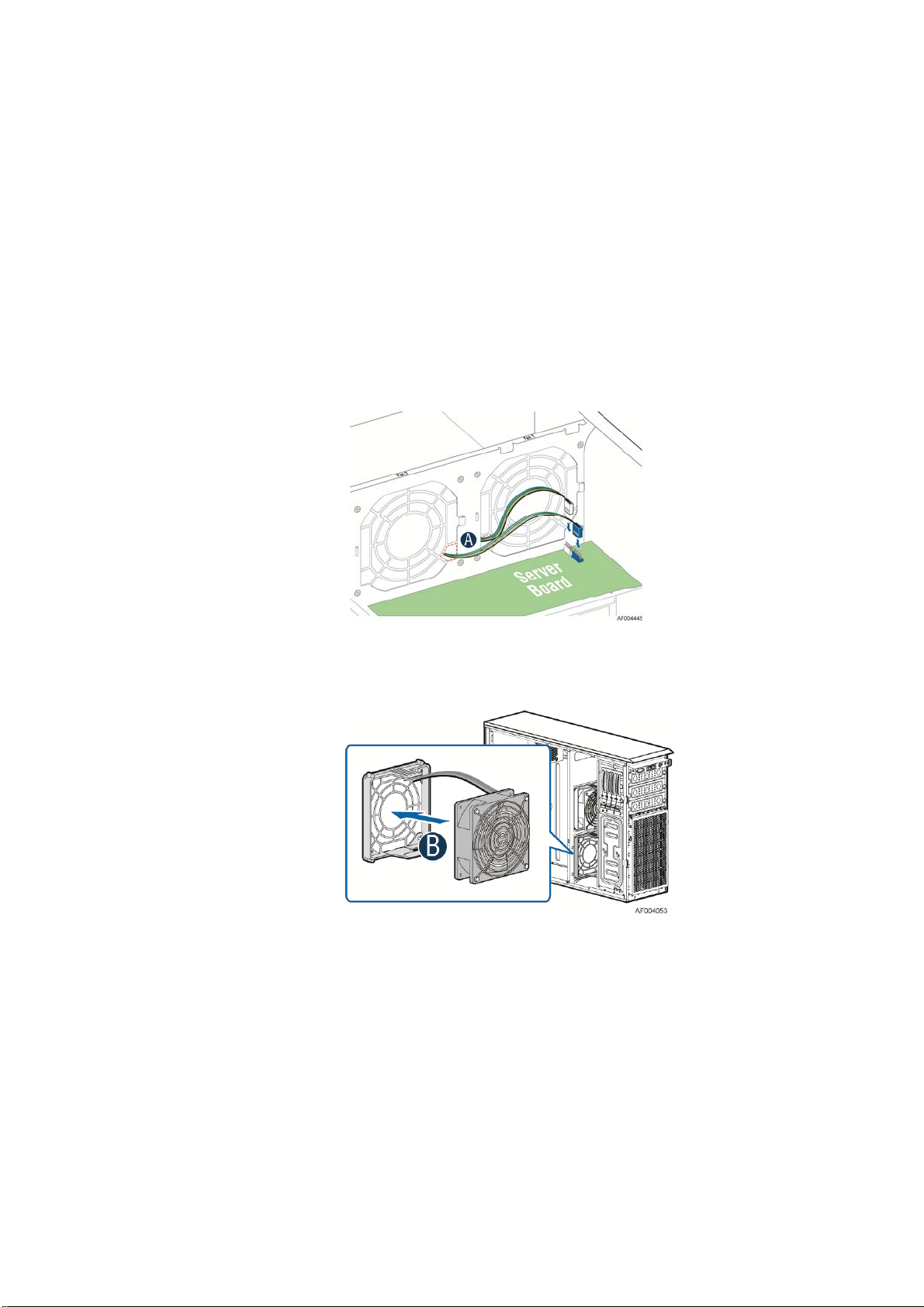
Installing the Fixed Fan
1. Observe the safety and ESD precautions at the beginning of this book.
2. Power down the server and unplug all peripheral devices and the AC power cable.
3. Remove the chassis cover. For instruct io ns, see “R emo ving the Chassis Cover”.
4. Remove the air duct if the air duct is installed. For instructions, see “Removing the
Airduct”.
5. Insert the fan cable in the fan brack et as the figure15 show (see letter “A”). Pay attention
to the fan cable connector color. The fan with blue fan cable connector should be installed
in fan2 bracket; the fan with white fan connector should be installed in fan 1 bracket.
Hardware Installations and Upgrades
Figure 83. Inserting the fan cable in the corresponding fan bracket
6. Install the fixed fan in the corresponding fan bracket (see letter “B”).
Figure 84. Installing the Fixed Fan
7. Connect fan power cable to the server/workstation board. See the Quick Start User’s Guide
or Service Guide provided with your Intel server/workstation board for appropriate
connection location.
®
Server Board S2600CP Intel® Server System P4000CP Family Service Guide (Preliminary) 51
Intel
Page 66

Hardware Installations and Upgrades
Replacing a Hot-swap Fan
NOTE
/
This procedure applies only to the Intel® Server Chassis P4000M family with hot-swap fan
configuration.
Removing the Hot-swap Fan
1. Observe the safety and ESD precautions at the beginning of this book.
2. Power down the server and unplug all peripheral devices and the AC power cable.
3. Remove the chassis cover. For instruct io ns, see “R emo ving the Chassis Cover”.
4. Press latch on fan and pull o n handle to remove hot-swap fan from chassis.
Figure 85. Removing Hot-swap Fan
Installing the Hot-swap Fan
1. Observe the safety and ESD precautions at the beginning of this book.
2. Power down the server and unplug all peripheral devices and the AC power cable.
3. Remove the chassis cover. For instruct io ns, see “R emo ving the Chassis Cover”.
4. Insert hot-sw ap fan into correspon ding chassis slot until it clicks into place.
52 Intel
®
Server Board S2600CP Intel® Server System P4000CP Family Service Guide
Page 67

Hardware Installations and Upgrades
Figure 86. Installing Hot-swap Fan
Removing and Installing 8x3.5” Hot-swap Hard Drive
Cage Assembly
Removing 8x3.5” Hot-swap Hard Drive Cage Assembly
1. Observe the safety and ESD precautions at the beginning of this book.
2. Power down the server and unplug all peripheral devices and the AC power cable.
3. Remove the chassis cover. For instruct io ns, see “R emo ving the Chassis Cover”.
4. Remove the front bezel if it is installed. For instructions, see “Removing the Front Bezel
(Pedestal Only)”.
5. Disconnec t the po wer and data cables to the backplane.
6. Use screwdriver to release the hot-swap hard drive cage (see letter “A”) from the chassis
and remove the hot-swap hard drive cage (see letter “B”).
Figure 87. Removing the 8x3.5 ” Hot-swap HDD Cage Assembly
®
Server Board S2600CP Intel® Server System P4000CP Family Service Guide (Preliminary) 53
Intel
Page 68

Hardware Installations and Upgrades
Installing 8x3.5” Hot-swap Hard Drive Cage Assembly
CAUTION
It is critical that you connect the SAS/SATA data cables correctly from the SAS/SATA
backplane to your server board or RAID controller card. Failure to do so may result in
data loss.
1. Observe the safety and ESD precautions at the beginning of this book.
2. Power down the server and unplug all peripheral devices and the AC power cable.
3. Remove the chassis cover. For instruct io ns, see “R emo ving the Chassis Cover”.
4. Remove the front bezel if it is installed. For instructions, see “Removing the Front Bezel
(Pedestal Only)”.
5. Remove the Fixed HDD EMI Shield and Fixed HDD Tray if they are installed. For
instructions, see “Removing the Fixed HDD Tray” and “Removing the Fixed HDD EMI
Shield”
6. Install the 8x3.5” Ho t-Swap Hard Drive Cage.
A. Slide the 8x3.5” Hot-Swap Drive Cage into the slot (see letter “A”).
B. Secure the Hard Drive Cage with the Screw (see letter “B”).
Figure 88. Installing the 8x3.5” Hot-Swap Hard Drive Cage Assembly
7. Make the backp lane and server bo ard/RAID controller card cable connections. Refer to the
documentation for your server board and/or RAID controller card for instructions on
connecting backplane cables to your server board or RAID controller card.
A. Connect an I2C cable (letter “A`”).
B. Connect Mini SAS data cables (letter “B”).
C. Connect power cable (letter “C”).
54 Intel
®
Server Board S2600CP Intel® Server System P4000CP Family Service Guide
Page 69

Hardware Installations and Upgrades
Figure 89. 8x3.5” Hot Swap Backplane Cable Connections
8. Install the fro nt bezel. F or instructions, see “Installing the Front Bezel (Pedestal Only)”.
9. Install the air duct if the air duct is removed. For instructions, see “Installing the Airduct”.
10. Install the chassis cover. For instructions, see “Installing the Chassis Cover”.
11. Plug all peripheral devices and the AC power cable into the server.
12. Power up the server.
Removing and Installing 8x2.5” Hot-swap Hard Drive
Cage Assembly
Removing 8x2.5” Hot-swap Hard Drive Cage Assembly
1. Observe the safety and ESD precautions at the beginning of this book.
2. Power down the server and unplug all peripheral devices and the AC power cable.
3. Remove the chassis cover. For instruct io ns, see “R emo ving the Chassis Cover”.
4. Remove the front bezel if it is installed. For instructions, see “Removing the Front Bezel
(Pedesal Only)”.
5. Disconnec t the po wer and data cables to the backplane.
6. Use screwdriver to release the hot-swap hard drive cage (see letter “A”) from the chassis
and remove the hot-swap hard drive cage (see letter “B”).
®
Server Board S2600CP Intel® Server System P4000CP Family Service Guide (Preliminary) 55
Intel
Page 70

Hardware Installations and Upgrades
Figure 90. Removing the 8x2.5” HDD Cage Assembly
Installing 8x2.5” Hot-swap Hard Drive Cage Assembly
CAUTION
It is critical that you connect the SAS/SATA data cables correctly from the SAS/SATA
backplane to your server board or RAID controller card. Failure to do so may result in
data loss.
1. Observe the safety and ESD precautions at the beginning of this book.
2. Power down the server and unplug all peripheral devices and the AC power cable.
3. Remove the chassis cover. For instruct io ns, see “R emoving the Chassis Cover”.
4. Remove the front bezel if it is installed. For instructions, see “Removing the Front Bezel
(Pedestal Only)”.
5. Install the 8x2.5” Ho t-Swap Hard Drive Cage.
A. Slide the 8x2.5” Hot-Swap Drive Cage into the slot (see letter “A”).
B. Secure the Hard Drive Cage with the Screw (see letter “B”).
56 Intel
®
Server Board S2600CP Intel® Server System P4000CP Family Service Guide
Page 71

Hardware Installations and Upgrades
Figure 91. Installing the 8x2.5” Hot-Swap Hard Drive Cage Assembly
6. Make the backp lane and server bo ard/RAID controller card cable connections. Refer to the
documentation that came with your server board and/or RAID controller card for
instructions on connecting backplane cables to your server board or RAID controller card.
A. Connect an I2C_IN cable (letter A)
B. Connect MiniSAS data cables (letter B)
C. Connect power cable (letter C)
Figure 92. 8x2.5” Hot Swap Backplane Cable Connections
7. Install the fro nt bezel. F or instructions, see “Installing the Front Bezel (Pedestal Only)”.
8. Install the air duct if the air duct is removed. For instructions, see “Installing the Airduct”
9. Install the chassis cov er. For instructions, see “Installing the Chassis Cover”.
10. Plug all peripheral devices and the AC power cable into the server.
11. Power up the server.
®
Server Board S2600CP Intel® Server System P4000CP Family Service Guide (Preliminary) 57
Intel
Page 72

Hardware Installations and Upgrades
Removing and Installing the Hot-swap HDD EMI Shiled
NOTE
/
This procedure applies only to the Intel® Server Chassis P4000M family with 8x2.5” hot-swap
hard disk drive cage configuration.
Removing the Hot-swap HDD EMI Shiled
1. Observe the safety and ESD precautions at the beginning of this book.
2. Power down the server and unplug all peripheral devices and the AC power cable.
3. Remove the chassis cover. For instruct io ns, see “R emo ving the Chassis Cover”.
4. Remove the front bezel. For instructions, see “Removing the front bezel (Pedestal Only)”.
5. Remove the 8x2.5” Hot-swap HDD cage. For instructions, see “Removing 8x2.5” Hotswap Hard Disk Drive Cage with Backplane”
6. Lift the EMI shield (see letter “A”) and move EMI shield outward from the chassis (see
letter “B”).
Figure 93. Removing the Hot-swap HDD EMI Shield
Installing the Hot-swap HDD EMI Shiled
1. Fit the edges of the EMI S hield against the sides of the chassis (see letter “A”).
2. Wh ile p ressing the EMI Shield, slide the EMI Shield downwards until the latch es on the
EMI Shield are engaged with the chassis (see letter “B”).
®
58 Intel
Server Board S2600CP Intel® Server System P4000CP Family Service Guide
Page 73

Figure 94. Installing the Hot-swap HDD EMI Shield
Replacing the Backplane
Hardware Installations and Upgrades
Removing the Backplane
1. Remove all hot-swap drive carriers, regardless of whether or not a drive is installed in the
carrier.
2. Disconnec t all cables from the backplane.
3. For server system with 3.5 ” hard drive bay, do the following:
A. Remove the screw to release the hard drive cage (see letter “A”);
B. Slide the hard drive cage out of the server chass (see letter “B”);
Figure 95. Removing 3.5” hard drive backplane – remove the hard drive cage
C. Remove the screw as shown (see letter “A”);
D. Slide the backplane (see letter “B”);
E. Remove the backplane from the server chassis (see letter “C”).
®
Server Board S2600CP Intel® Server System P4000CP Family Service Guide (Preliminary) 59
Intel
Page 74

Hardware Installations and Upgrades
Figure 96. Removing 3.5” hard drive backplane - remove the backplane
4. For server system with 2.5 ” hard drive bay, do the following:
A. Remove the three screws to release the hard drive cage;
B. Slide the hard drive cage out of the server chassis;
Figure 97. Removing 2.5” hard drive backplane – remove the stiffener
C. Remove the screw fro m the backp lane board (see letter “A”);
D. Slide the backplane board to release it (see letter “B”);
E. Remove the backplane board from the four hooks and pull out of the hard drive cage (see
letter “C”).
60 Intel
®
Server Board S2600CP Intel® Server System P4000CP Family Service Guide
Page 75

Hardware Installations and Upgrades
Figure 98. Removing 2.5” hard drive backplane – remove the backplane
Installing the Backplane
1. Remove all hot-swap drive carriers, regardless of whether or not a drive is installed in the
carrier.
2. For server system with 3.5 ” hard drive bay, do the following:
A. Align the backplane board with the hooks on the hard drive cage (see letter “A”);
B. Slide the bac kplane into the drive cage (see letter “B”);
C. Secure the backplane with screws (see letter “C”);
®
Server Board S2600CP Intel® Server System P4000CP Family Service Guide (Preliminary) 61
Intel
Page 76

Hardware Installations and Upgrades
Figure 99. Installing 3.5” hard drive backplane – install the backplane
D. Insert the hard drive cage into server chassis (see letter “A”);
E. Secure the hard drive cage with the screws (see letter “B”);
Figure 100. Installing 3.5” hard drive backplane – install the hard drive cage
3. For server system with 2.5 ” hard drive bay, do the following:
A. Align the backplane board with the hooks on the hard drive cage (see letter “A”);
B. Slide the bac kplane board in the direction shown to lock it in place (see letter “B”);
C. Secure the backp lane with the screw as shown (see letter “C”);
62 Intel
®
Server Board S2600CP Intel® Server System P4000CP Family Service Guide
Page 77

Hardware Installations and Upgrades
Figure 101. Installing 2.5” hard drive backplane – install backplane
F. Insert the hard drive cage into server chassis (see letter “A”);
G. Secure the hard drive cage with the screws (see letter “B”);
Figure 102. Installing 2.5” hard drive backplane – install hard drive cage
Removing and Installing the Top Cosmetic Cover
Removing the Top Cosmetic Cover
1. Observe the safety and ESD precautions at the beginning of this book.
2. Power down the server and unplug all peripheral devices and the AC power cable.
3. Remove the chassis cover. For instructions, see “Removing the Chassis Cover”.
®
Server Board S2600CP Intel® Server System P4000CP Family Service Guide (Preliminary) 63
Intel
Page 78

Hardware Installations and Upgrades
4.
Press the latches under the top cosmetic cover to release the cosmetic cover (see letter “A”)
and remove the top cosmetic cover (see letter “B”).
Figure 103. Removing the Top Cosmetci Cover
Installing the Top Cosmetic Cover
1. Observe the safety and ESD precautions at the beginning of this book.
2. Power down the server and unplug all peripheral devices and the AC power cable.
3. Attach the top cosmetic cover to the chassis and make sure the edges of the top cosmetic
cover fit the sides of the chassis top. Then slide the top cosmetic cover forward until the
latches on the top cosmetic cover are engaged with the chassis.
Figure 104. Installing the Top Cosmetci Cover
Removing and Installing the Chassis Feet
Removing the Chassis Feet
1. Observe the safety and ESD precautions at the beginning of this book.
®
64 Intel
Server Board S2600CP Intel® Server System P4000CP Family Service Guide
Page 79

Hardware Installations and Upgrades
2. Power down the server and unp lug all peripheral devices and the AC pow er cable.
3. Lay the chassis down on its right side.
4. Loose the screws securing the rubber fo ott to the chassis and then remove the rubber foott from
chassis.
Figure 105. Removing the Chassis Feet
5. Repeat above steps un t il all four feet are removed.
Installing the Chassis Feet (Pedestal Configuration Only)
NOTE
/
Do not install feet on your Intel® Server Chassis P4000M family if it is to be installed in a
rack. Only install feet on a pedestal-configured chassis.
1. Observ e the safe ty and ESD precautions at the beginning of this book.
2. Power down the server and unp lug all peripheral devices and the AC pow er cable.
3. Lay the chassis down on its right side.
4. Insert rubber foot into chassis hole (see letter “A”).
5. Secure foot by inserting screw through the rubber foot (see letter “B”).
6. Repeat above steps until all four feet are installed.
®
Server Board S2600CP Intel® Server System P4000CP Family Service Guide (Preliminary) 65
Intel
Page 80

Hardware Installations and Upgrades
Figure 106. Installing the Chassis Feet
7. Put chassis in the upright position.
8. Reconnect all peripheral devices and the AC power cable to the server. Power up the server.
Removing and Installing the Front Panel Tray
CAUTION
The front panel is NOT hot swappable. Before removing or replacing the control panel,
you must first take the server out of service, turn off all peripheral devices connected to
the system, turn off the system by pressing the power button, and unplug the AC power
cord from the system or wall outlet.
Removing the Front Control Panel Tray
1. Observe the safety and ESD precautions at the beginning of this book.
2. Power down the server and unplug all peripheral devices and the AC power cable.
3. Remove the chassis cover. For instruct io ns, see “R emoving the Chassis Cover”.
4. Remove the front bezel if it is installed. For instructions, see “Removing the Front Bezel”.
5. Remove the air duct if it is installed.
6. Disconnec t the front panel cable, U SB cable from the server board
66 Intel
®
Server Board S2600CP Intel® Server System P4000CP Family Service Guide
Page 81

Hardware Installations and Upgrades
Figure 107. Disconnecting the Cables from the Server Board
7. Loose the front panel cable and USB cable from the wire clip on chassis
8. Press the latch at the sides of the front panel (see Letter “A”) and carefully slide the front
panel out (see Letter “B”).
CAUTION
Do not slide the front panel out far from the front of the chassis before you
disconnect the instruction cable from the front panel board.
Figure 108. Sliding the Front Panel Tray out from the Chassis
9. Slide the front panel out fro m the front of the chassis to the p lace (see Letter “C”) so that
you can reach the front panel cable and instrustion cable connectors at the rear of the front
panel. Then disconnect the front panel cable and intrusion switch cable from the front panel
board (see Letter “D”).
®
Server Board S2600CP Intel® Server System P4000CP Family Service Guide (Preliminary) 67
Intel
Page 82

Hardware Installations and Upgrades
Figure 109. Disconnecting the Cables from Front Panel Board
10. Slide the front panel tray out.
Installing the Fron Panel Tray
1. O bserve the safety and ESD precautions at the beginning of this book.
2. Power down the server and unplug all peripheral devices and the AC power cable.
3. Remove the c hassis cover. For instruc tions, see “Removing the Chassis Cover”.
4. Re move the front bezel if it is installed. For instructions, see “Removing the Front Bezel”.
5. Remove the a ir duct if it is installed.
6. A ttach the front panel cable and the chassis in trusion cable (see Letter “A”) to the front panel
board.
68 Intel
Figure 110. Connecting the Cables to the Front Panel Board
®
Server Board S2600CP Intel® Server System P4000CP Family Service Guide
Page 83

Hardware Installations and Upgrades
7. Slide the fron t panel tray in chassis
Figure 111. Installing the Front Panel Tray in Chassis
8. Connect the front panel and USB cables to server board.
Figure 112. Connecting the Cables to Server Board the Front Panel Tray in Chassis
9. In stall the front bezel. For instructions, see “Removing and Installing the Front Bezel”.
10. Install the air duct based on board requ iremen t.
11. Install the chassis cover. For instructions, see “Installing the Cha ssis Cover”.
12. Plug all peripheral devices an d the AC power cable into the server.
13. Power up the server.
Replacing the Front Panel Board
1. Observe the safety and ESD precautions at the beginning of this book.
2. Power down the server and unplug all peripheral devices and the AC power cable.
3. Remove the chassis cover. For instructio ns, see “Removing the Chassis Cover”.
4. Remove the front bezel if it is installed. For instructions, see “Removing the Front Bezel”.
®
Server Board S2600CP Intel® Server System P4000CP Family Service Guide (Preliminary) 69
Intel
Page 84

Hardware Installations and Upgrades
5. Remove the front panel tray if it is installed. For instructions, see “Removing the Front
Panel Tray”.
6. Loose the screw “see Letter “A”) securing the front panel board and remove the front
panel board (see Letter “B”).
7. Remove the cap on the front pane l board power button and install the new cap on the new
front panel board power button.
Figure 113. Removing the Front Panel Board
Figure 114. Removing and Installing the Cap on Front Panel Board
8. Attach the new front panel board in the front panel tray (see letter “A”) and secure the new
front panel board with the screw (see letter “B”).
Figure 115. Installing the New Front Panel Board
9. Installing the front panel tray with the front panel board. For instructions, see “Installing
the Front Panel Tray”.
10. Install the front bezel. For instructions, see “Re movin g and Installing the Front Bezel”.
11. Install the air duct based on board requirement.
14. Install the chassis cover. For instructions, see “Installing the Chassis Cover”.
70 Intel
®
Server Board S2600CP Intel® Server System P4000CP Family Service Guide
Page 85

15. Plug all peripheral devices and the AC power cable into the server.
16. Power up the server.
Installing Alternate Serial Port
1. Observe the safety and ESD precautions at the beginning of this book.
2. Power down the server and unplug all peripheral devices and the AC power cable.
3. Remove the chassis cover. For instruct io ns, see “R emo ving the Chassis Cover”.
4. Remove the alternate serial port knockout by pressing the knocko ut from inside the chassis.
Hardware Installations and Upgrades
Figure 116. Removing the Alternate Serial Port Knockout
5. Install the serial port on the rear panel of the chassis. And connect the cable to the Serial B
Connector on your motherboard.
Figure 117. Installing the Alternate Serial Port Knockout
®
Server Board S2600CP Intel® Server System P4000CP Family Service Guide (Preliminary) 71
Intel
Page 86

Hardware Installations and Upgrades
Installing and/or Removing a Expander card
Installing the Expander card
1. Observe the safety and ESD precautions at the beginning of this book.
2. Power down the server and unplug all peripheral devices and the AC power cable.
3. Remove the chassis cover. For instruct io ns, “Re mov ing the Chassis Cover”.
4. Remove the fans. For instructions, see “Re moving the F ixed Fan ” o r “Removing the
Hot-swap Fans”.
5. Remove the Fixed HDD s or Hotswap drive cages. For instructions, see “Remove Fixed
Hard Drives”, or “Remove 8x3.5 Hotswap Drive Cage Assemble”, or “Remove 8x2.5
Hotswap Drive Cage Assemble”
6. Locate the expander card bracket in the chassis. Mount the expand er card to th e b racket
with screws.
Figure 118. Installing the Expander Card
7. Connect the data cable between server board and expander card, and between expand er and
backplane(s). See documents for your server boards for instructions.
8. Install the Fixed HDDs or Hotswap drive cages. For instructions, see “Install Fixed Hard
Drives”, or “Install 8x3.5 Hotswap Drive Cage Assemble”, or “Install 8x2.5 Hotswap Drive
Cage Assemble”
9. Install the fans. For instructions, see “Install the Fixed Fan” or “Install the Hot-swap
Fans”.
10. Install the chassis cover. For instructions, “Install the Chassis Cover”.
Removing the Expander card
1. Observe the safety and ESD precautions at the beginning of this book.
2. Power down the server and unplug all peripheral devices and the AC power cable.
3. Remove the chassis cover. For instruct io ns, “Re mov ing the Chassis Cover”.
®
72 Intel
Server Board S2600CP Intel® Server System P4000CP Family Service Guide
Page 87

Hardware Installations and Upgrades
4. Remove the fans. For instructions, see “Re moving the F ixed Fan ” o r “Removing the
Hot-swap Fans”.
5. Remove the Fixed HDD s or Hotswap drive cages. For instructions, see “Remove Fixed
Hard Drives”, or “Remove 8x3.5 Hotswap Drive Cage Assemble”, or “Remove 8x2.5
Hotswap Drive Cage Assemble”
6. Unplug all the cables connected to the expander card.
7. Remove the expand er card from expander card bracket by releasing the securing screws.
Figure 119. Removing the Expander card
8. Install the Fixed HDDs or Hotswap drive cages. For instructions, see “Install Fixed Hard
Drives”, or “Install 8x3.5 Hotswap Drive Cage Assemble”, or “Install 8x2.5 Hotswap Drive
Cage Assemble”
9. Install the fans. For instructions, see “Install the Fixed Fan” or “Install the Hot-swap
Fans”.
10. Install the chassis cover. For instruction s, see “Install the Chassis Cover”.
®
Server Board S2600CP Intel® Server System P4000CP Family Service Guide (Preliminary) 73
Intel
Page 88

Hardware Installations and Upgrades
3 Server Utilities
Using the BIOS Setup Utility
This section describes the BIOS Setup Utility options, which is used to change server configuration
defaults. You can run BIOS Setup with or without an operating system being present.
Starting Setup
To enter the BIOS Setup using a keyboard (or emulated keyboard); press the <F2> function key
during boot time when the OEM or Intel
®
logo is displayed. The following message is displayed on
the diagnostics screen and under the Quiet Boot logo screen:
Press <F2> to enter setup
When the Setup Utility is entered, the Main screen is displayed. However, serious errors cause the
system to display the Error Manager screen instead of the Main screen.
Setup Navigation Keyboard Commands
The bottom right portion of the Setup screen provides a list of commands that are used to navigate
through the Setup utility. These commands are displayed at all times.
Each Setup menu page contains a number of features. Each feature is associated with a value field,
except those used for informative purposes. Each value field contains configurable parameters.
Depending on the security option chosen and in effect by the password, a menu feature’s value may
or may not be changed. If a value cannot be changed, its field is made inaccessible and appears
grayed out.
Table 2. BIOS Setup: Keyboard Command Bar
Key Option Description
<Enter> Execute Command The <Enter> key is used to activate submenus when the selected feature is a submenu, or to
display a pick list if a selected option has a value field, or to select a subfield for multivalued features like time and date. If a pick list is displayed, the <Enter> key selects the
currently highlighted item, undoes the pick list, and returns the focus to the parent menu.
<Esc> Exit The <Esc> key provides a mechanism for backing out of any field. When the <Esc> key is
pressed while editing any field or selecting features of a menu, the parent menu is reentered.
When the <Esc> key is pressed in any submenu, the parent menu is re-entered. When the
<Esc> key is pressed in any major menu, the exit confirmation window is displayed and the
user is asked whether changes can be discarded. If “No” is selected and the <Enter> key is
pressed, or if the <Esc> key is pressed, the user is returned to where they were before
<Esc> was pressed, without affecting any existing settings. If “Yes” is selected and the
<Enter> key is pressed, the setup is exited and the BIOS returns to the main System
Options Menu screen.
Select Item The down arrow is used to select the next value in a menu item’s option list, or a value
Select Menu The left and right arrow keys are used to move between the major menu pages. The keys
Select Item The up arrow is used to select the previous value in a pick list, or the previous option in a
menu item's option list. The selected item must then be activated by pressing the <Enter>
key.
field’s pick list. The selected item must then be activated by pressing the <Enter> key.
have no effect if a sub-menu or pick list is displayed.
74 Intel
®
Server Board S2600CP Intel® Server System P4000CP Family Service Guide
Page 89

Hardware Installations and Upgrades
Key Option Description
<Tab> Select Field The <Tab> key is used to move between fields. For example, <Tab> can be used to move
from hours to minutes in the time item in the main menu.
- Change Value The minus key on the keypad is used to change the value of the current item to the previous
value. This key scrolls through the values in the associated pick list without displaying the
full list.
+ Change Value The plus key on the keypad is used to change the value of the current menu item to the next
value. This key scrolls through the values in the associated pick list without displaying the
full list. On 106-key Japanese keyboards, the plus key has a different scan code than the
plus key on the other keyboards, but will have the same effect.
<F9> Setup Defaults Pressing the <F9> key causes the following to display:
Load Optimized Defaults?
Yes No
If “Yes” is highlighted and <Enter> is pressed, all Setup fields are set to their default
values. If “No” is highlighted and <Enter> is pressed, or if the <Esc> key is pressed, the
user is returned to where they were before <F9> was pressed without affecting any existing
field values.
<F10> Save and Exit Pressing the <F10> key causes the following message to display:
Save configuration and reset?
Yes No
If “Yes” is highlight ed and <Enter> is presse d, all changes are saved and the Setup is
exited. If “No” is highlighted and <Enter> is pressed, or the <Esc> key is pressed, the user
is returned to where they were before <F10> was pressed without affecting any existing
values.
Setup Screen Menu Selection Bar
The Setup Screen Menu selection bar is located at the top of the BIOS Setup Utility screen. It
displays tabs showing the major screen selections available to the user. By using the left and right
arrow keys, the user can select the listed screens. Some screen selections are out of the visible menu
space, and become available by scrolling to the left or right of the current selections displayed.
BIOS Setup Utility Screens
The following sections describe the screens available in the BIOS Setup utility for the configuration
of the server platform.
For each of these screens, there is an image of the screen with a list of Field Descriptions which
describe the contents of each item on the screen. Each item on the screen is hyperlinked to the
relevant Field Description. Each Field Description is hyperlinked back to the screen image.
These lists adhere to the following guidelines:
The text heading for each Field Description is the actual text as displayed on the BIOS
Setup screen. This screen text is a hyperlink to its corresponding Field Description.
The text shown in the Option Values and Help Text entries in each Field Description are
the actual text and values are displayed on the BIOS Setup screens.
®
Server Board S2600CP Intel® Server System P4000CP Family Service Guide (Preliminary) 75
Intel
Page 90

Hardware Installations and Upgrades
In the Option Values entries, the text for default values is shown with an underline. These
values do not appear underline on the BIOS Setup screen. The underlined text in this
document is to serve as a reference to which value is the default value.
The Help Text entry is the actual text which appears on the screen to accompany the item
when the item is the one in focus (active on the screen).
The Comments entry provides additional information where it may be helpful. This
information does not appear on the BIOS Setup screens.
Information enclosed in angular brackets (< >) in the screen shots identifies text that can
vary, depending on the option(s) installed. For example, <Amount of memory installed> is
replaced by the actual value for “Total Memory”.
Information enclosed in square brackets ([ ]) in the tables identifies areas where the user
must type in text instead of selecting from a provided option.
Whenever information is changed (except Date and Time), the systems requires a save and
reboot to take place in order for the changes to take effect. Alternatively, p ressing <ESC>
discards the changes and resumes POST to continue to boot the system according to the
boot order set from the last boot.
Map of Screens and Functionality
There are a number of screens in the entire Setup collection. They are organized into major
categories. Each category has a hierarchy beginning with a top-level screen from which lower-level
screens may be selected. Each top-level screen appears as a tab, arranged across the top of the Setup
screen image of all top-level screens.
There are more categories than will fit across the top of the screen, so at any given time there will
be some categories which will not appear until the user has scrolled across the tabs which are
present.
The categories and the screens included in each category are listed below, with links to each of the
screens named.
Table 3. Screen Map
Categories (Top Tabs) 2nd Level Screens 3rd Level Screens
Main Screen (Tab)
Advanced Screen (Tab)
Processor Configuration
Memory Configuration
Mass Storage Controller
Configuration
PCI Configuration
Memory RAS and Performance
Configuration
76 Intel
Serial Port Configuration
®
Server Board S2600CP Intel® Server System P4000CP Family Service Guide
Page 91

Hardware Installations and Upgrades
Categories (Top Tabs) 2nd Level Screens 3rd Level Screens
[With BMC Only]
[Non-BMC Only]
USB Configuration
System Acoustic and Performance
Configuration
Hardware Monitor
[Non-BMC Only]
Realtime Temperature and Voltage
Status
Security Screen (Tab)
Server Management Screen (Tab)
[With BMC Only]
Console Redirection
System Information
BMC LAN Configuration
Boot Options Screen (Tab)
CDROM Order
Hard Disk Order
Floppy Order
Network Device Order
BEV Device Order
Add EFI Boot Option
Delete EFI Boot Option
Boot Manager Screen (Tab)
Error Manager Screen (Tab)
[Non-BMC Only]
View Event Log Screen
Exit Screen (Tab)
®
Server Board S2600CP Intel® Server System P4000CP Family Service Guide (Preliminary) 77
Intel
Page 92

Hardware Installations and Upgrades
Main Screen (Tab)
The Main Screen is the first screen that appears when the BIOS Setup configuration utility is entered,
unless an error has occurred. If an error has occurred, the Error Manager Screen appears instead.
Figure 120. Main Screen
Main Advanced Security Server Management Boot Options
Logged in as:
Administrator/User
Platform ID <Platform Identification String>
System BIOS
BIOS Version <Platform.86B.xx.yy.zzzz>
Build Date <MM/DD/YYYY>
Memory
Total Memory <Amount of memory installed>
Quiet Boot Enabled/Disabled
POST Error Pause Enabled/Disabled
System Date [Day MM/DD/YYYY]
System Time [HH:MM:SS]
Boot Manager
Screen Field Descriptions
:
1. Logged in as:
Option Values: <Administrator / User>
Help Text: <None>
Comments: Information only
Administrator or User. With no passwords set, Administrator is the default mode.
Back to [Main Screen]
78 Intel
. Displays password level that setup is running in:
®
Server Board S2600CP Intel® Server System P4000CP Family Service Guide
Page 93

2. Plat form ID
Option Values: < Platform ID>
Help Text: <None>
Hardware Installations and Upgrades
Comments: Information only
. Displays the Platform ID (Board ID) for the board on
which the BIOS is executing POST.
The Platform ID is limited to 8 characters, because it is also used in the ACPI Tables which have
that limitation. In some cases, this means that the Platform ID is abbreviated from the marketin g
designation.
Back to [Main Screen]
3. BIOS Version
Option Values: <Current BIOS version ID>
Help Text: <None>
Comments: Information only
. The BIOS version displayed uniquely identifies the
BIOS that is currently installed and operational on the board. The version information displayed
is taken from the BIOS ID String, with the timestamp segment dropped off. The segments
displayed are:
Platform: Identifies that t his is the correct platform BIOS
86B: Identifies this BIOS as being an Intel Server BIOS
xx: Major Revision level of the BIOS
yy: Release Revision level for this BIOS
zzzz: Release Number for this BIOS
Back to [Main Screen]
4. Build Date
Option Values: <Date and time when the currently installed BIOS was created (built)>
Help Text: <None>
Comments: Information only
. The time and date displayed are taken from the
timestamp segment of the BIOS ID String.
Back to [Main Screen]
5. Total Memory
Option Values: <Amount of memory installed in the system>
Help Text: <None>
Comments: Information only
. Displays the total physical memory ins talled in the
system, in MB or GB. The term physical memory indicates the total memory discovered in the
form of installed DDR3 DIMMs.
Back to [Main Screen]
®
Server Board S2600CP Intel® Server System P4000CP Family Service Guide (Preliminary) 79
Intel
Page 94

Hardware Installations and Upgrades
6. Quiet Boot
Option Values: Enabled
Disabled
Help Text:
[Enabled] – Display the logo screen during POST.
[Disabled] – Display the diagnostic screen during POST.
Comments: This field controls whether the full diagnostic information is displayed
on the screen during POST.
Back to [Main Screen]
7. POST Error Pause
Option Values: Enabled
Disabled
Help Text:
[Enabled] – Go to the Error Manager for critical POST errors.
[Disabled] – Attempt to boot and do not go to the Error Manager for critical POST
errors.
Comments: If enabled, the POST Error Pause option takes the system to the error
manager to review the errors when major errors occur. Minor and fatal error displays are not
affected by this setting.
Back to [Main Screen]
8. System Date
Option Values: <System Date initially displays the current system calendar date,
including the day of the week>
Help Text:
System Date has configurable fields for the current Month, Day, and Year.
The year must be between 2005 and 2099.
Use [Enter] or [Tab] key to select the next field.
Use [+] or [-] key to modify the selected field.
Comments: This field will initially display the current system day of week and date.
It may be edited to change the system date. When the System Date is reset by the “BIO S Defaults”
jumper, BIOS Recovery Flash Update, or other method, the date will be the earliest date in the
allowed range – Saturday 01/01/2005.
Back to [Main Screen]
80 Intel
®
Server Board S2600CP Intel® Server System P4000CP Family Service Guide
Page 95

9. System Time
Option Values: <System Time initially displays the current system time of day, in 24-
hour format>
Help Text:
Comments: This field will initially display the current system time (24 hour time). It
may be edited to change the system time. When the System Time is reset by the “BIOS Defaults”
jumper, BIOS Recovery Flash Update, or other method, the time will be the earliest time of day
in the allowed range – 00:00:00 (although the time will be updated beginning from when it is
reset early in POST).
Back to [Main Screen]
Hardware Installations and Upgrades
System Time has configurable fields for Hours, Minutes, and Seconds.
Hours are in 24-hour format.
Use the [Enter] or [Tab] key to select the next field.
Use the [+] or [-] key to modify the selected field.
®
Server Board S2600CP Intel® Server System P4000CP Family Service Guide (Preliminary) 81
Intel
Page 96

Hardware Installations and Upgrades
Advanced Screen (Tab)
The Advanced screen provides an access point to configure several groups of options. On this screen, the
user can select the option group to be configured. Configuration actions are performed on the selected
screen, and not directly on the Advanced screen.
This screen is the same for all board series, selecting between the same groups of options, although the
options for different boards are not necessarily identical.
To access this screen from the Main screen or other top -leve l “Tab” screen, press the right or left a rrow
keys to traverse the tabs at the top of the Setup screen until the Advanced screen is s elected.
Figure 121. Advanced Screen
Main Advanced Security Server Management Boot Options
► Processor Configuration
► Memory Configuration
► Mass Storage Controller Configuration
► PCI Configuration
► Serial Port Configuration
► USB Configuration
► System Acoustic and Performance Configuration
Screen Field Descriptions
:
1. Processor Configuration
Option Values: <None>
Help Text: View/Configure processor information and settings.
Comments: Selection only
. Position to this line and press the <Enter> key to go to the
Processor Configuration group of configuration settings.
Back to [Advanced Screen]
Boot Manager
2. Me mory Configuration
Option Values: <None>
Help Text:
View/Configure memory information and settings.
Comments: Selection only
. Position to this line and press the <Enter> key to go to the
Memory Configuration group of configuration settings.
Back to [Advanced Screen]
®
82 Intel
Server Board S2600CP Intel® Server System P4000CP Family Service Guide
Page 97

3. Mass Storage Controller Configuration
Option Values: <None>
Help Text:
View/Configure mass storage controller information and settings.
Hardware Installations and Upgrades
Comments: Selection only
. Position to this line and press the <Enter> key to go to the
Mass Storage Controller Configuration group of configurat ion settings.
Back to [Advanced Screen]
4. PCI Configuration
Option Values: <None>
Help Text:
View/Configure PCI information and settings.
Comments: Selection only
. Position to this line and press the <Enter> key to go to the
PCI Configuration group of configuration settings.
Back to [Advanced Screen]
5. Serial Port Configuration
Option Values: <None>
Help Text:
View/Configure serial port information and settings.
Comments: Selection only
. Position to this line and press the <Enter> key to go to the
Serial Port Configuration group of configuration settings.
Back to [Advanced Screen]
6. USB Configuration
Option Values: <None>
Help Text:
View/Configure USB information and settings .
Comments: Selection only
. Position to this line and press the <Enter> key to go to the
USB Configuration group of configuration settings.
Back to [Advanced Screen]
7. System Acoustic and Performance Configuration
Option Values: <None>
Help Text:
View/Configure system acoustic and performance information and settings.
Comments: Selection only
. Position to this line and press the <Enter> key to go to the
System Acoustic and Performance Configuration group of configuration settings.
Back to [Advanced Screen]
®
Server Board S2600CP Intel® Server System P4000CP Family Service Guide (Preliminary) 83
Intel
Page 98

Hardware Installations and Upgrades
Processor Configuration
The Processor Configuration screen displays the processor identification and microcode level, core
frequency, cache sizes, Intel
®
QuickPath Interconnect (QPI) information for all processors currently
installed. It also allows the user to enable or disable a number of processor options.
To access this screen from the Main screen, select Advanced > Processor Configuration. To move to
another screen, press the <Esc> key to return to the Advanced screen, then select the desired screen.
84 Intel
®
Server Board S2600CP Intel® Server System P4000CP Family Service Guide
Page 99

Hardware Installations and Upgrades
Figure 122. Processor Configuration Screen
Advanced
Processor Configuration
Processor Socket CPU 1 CPU 2
Processor ID <CPUID>* | <CPUID>
Processor Frequency <Proc Freq> | <Proc Freq>
Microcode Revision <Rev data> | <Rev data>
L1 Cache RAM
L2 Cache RAM
<L1 Cache Size> | <L1 Cache Size>
<L2 Cache Size> | <L2 Cache Size>
L3 Cache RAM <L3 Cache Size> | <L3 Cache Size>
Processor 1 Version <ID string from Processor 1>
Processor 2 Version <ID string from Processor 2>
Current Intel® QPI Link Speed Slow/Fast
Intel® QPI Link Frequency N/A / 6.4 GT/s / 7.2 GT/s / 8.0 GT/s / Unknown GT/s
Intel® QPI Frequency Select Auto Max / 6.4 GT/s / 7.2 GT/s / 8.0 GT/s
Intel® Turbo Boost Technology Enabled/Disabled
Enhanced Intel SpeedStep® Tech Enabled/Disabled
Processor C3 Enabled/Disabled
Processor C6 Enabled/Disabled
Intel® Hyper-Threading Tech Enabled/Disabled
Active Processor Cores All/1/2/3/4/5/6/7
Execute Disable Bit Enabled/Disabled
Intel® Virtualization Technology Enabled/Disabled
Intel® VT for Directed I/O Enabled/Disabled
MLC Streamer Enabled/Disabled
MLC Spatial Prefetcher Enabled/Disabled
DCU Data Prefetcher Enabled/Disabled
DCU Instruction Prefetcher Enabled/Disabled
Direct Cache Access (DCA) Enabled/Disabled
Enhanced Error Containment Mode Enabled/Disabled
SMM Wait Timeout [0 – 3000ms, 3 is default]
®
Server Board S2600CP Intel® Server System P4000CP Family Service Guide (Preliminary) 85
Intel
Page 100

Hardware Installations and Upgrades
Screen Field Descriptions:
1. Processor ID
Option Values: <CPUID>
Help Text: <None>
Comments: Information only
. Displays the Processor Signature value (from the
CPUID instruction) identifying the type of processor and the stepping.
For multi-socket boards, the processor selected as the Bootstrap Processor (BSP) has an asterisk
(“*”) displayed beside the Processor ID. “N/A” will be displayed for a processor if not installed.
S1400 or S1600
S2400 or S2600
series boards have 4 Processor ID displays.
S4600
series boards have a single Processor ID display
series boards have 2 Processor ID displays.
Back to [Processor Configuration Screen] — [Advanced Screen]
2. Processor Frequency
Option Values: <Current Processor Operating Frequency>
Help Text: <None>
Comments: Information only
. Displays current operating frequency of the processor.
Single socket boards have a single processor display, 2 sockets or 4 sockets boards have a display
column for each socket, showing “N/A” for empty sockets where processors are not installed.
Back to [Processor Configuration Screen] — [Advanced Screen]
3. Microcode Revision
Option Values: <Microcode Revision Number>
Help Text: <None>
Comments: Information only
processor microcode.
Single socket boards have a single processor display, 2 sockets or 4 sockets boards have a display
column for each socket, showing “N/A” for empty sockets where processors are not installed.
Back to [Processor Configuration Screen] — [Advanced Screen]
4. L1 Cache RAM
Option Values: <L1 cache size>
Help Text: <None>
Comments: Information only
L1 cache is not shared between cores, this is shown as the amount of L1 cache per core
two types of L1 cache, so this amount is the total of L1 Instruction Cache
each core.
Single socket boards have a single processor display, 2 sockets or 4 sockets boards have a display
column for each socket, showing “N/A” for empty sockets where processors are not installed.
Back to [Processor Configuration Screen] — [Advanced Screen]
86 Intel
. Displays Revision Level of the currently loaded
. Displays size in KB of the processor L1 Cache. Since
. There are
plus L1 Data Cache for
®
Server Board S2600CP Intel® Server System P4000CP Family Service Guide
 Loading...