

Page 1

Quick Installation Guide
Version 1.0
P0715
7" Compact Intel Low Voltage
PIII / Celeron Panel PC
Page 2

Copyright© 2006
All Rights Reserved.
The information in this document is subject to change without prior notice in
order to improve the reliability, design and function. It does not represent a
commitment on the part of the manufacturer.
Under no circumstances will the manufacturer be liable for any direct, indirect,
special, incidental, or consequen-tial damages arising from the use or inability to
use the product or documentation, even if advised of the possibility of such
damages.
This document contains proprietary information protected by copyright. All rights
are reserved. No part of this manual may be reproduced by any mechanical,
electronic, or other means in any form without prior written permission of the
manufacturer.
About this installation guide
This manual provides general information and installation instructions about the
product. This Quick Installation is intended for experienced users and integrators
with hardware knowledge of personal computers. If you are not sure about any
description in this Quick Installation, please consult your vendor before further
handling.
2 P0715 Quick Installation
Page 3

Warning
Panel PC and their components contain very delicate Integrated Circuits
(IC). To protect the Panel PC and its components against damage from
static electricity, you should always follow the following precautions
when handling it :
1. Disconnect your Panel PC from the power source when you want to work on
the inside
2. Hold the board by the edges and try not to touch the IC chips, leads or
circuitry
3. Use a grounded wrist strap when handling computer components.
4. Place components on a grounded antistatic pad or on the bag that came with
the Single Board Computer, whenever components are separated from the
system
5. It possibly needs BIOS support in the case of using special backplane,
otherwise, it might be not able to function completely.
6. Please make sure the power connector is tightly plugged into the power
socket before power on.
P0715 Quick Installation
3
3
Page 4

Getting Started
This section will help you have your P0715 up and running
smoothly.
PACKING LIST
P0715
9 x Screws
1 x Arm Holder Bracket
2 x Wall Mount Bracket
1 x Adaptor
2 x Power Cord (American & French Cordset)
1 x Driver CD
Before up and running, please make sure the package contains
all of above accessories.
If any of the above items is damaged or missing, contact your
vendor immediately.
4 P0715 Quick Installation
Page 5

Model Name
System
I/O
LCD Display
Storage
Power Supply
Mechanical &
Environmental
Specification
Panel PC P0715
CPU
Cache 2nd Level 256K
Memory 1 x 144Pin SO-DIMM up to 512MB SDRAM
VRAM SMI722 G8 Lynx 3D+ engine 8MB Video RAM on chip
Chipset Intel 815E + Intel CH2
ATA / IDE Ultra DMA 33, support 2 IDE device
Audio Realtek ALC202A AC97 Codec, support Line-out
Watchdog Timer 127-level Reset
System Fan 1 x 4cm x 4cm / 8 CFM
Serial Port 2 x RS-232 ports (COM1/2)
USB Port 2 x USB 1.1 compliant
KB / MS 1 x PS2 K/B and 1 x Mouse
Speaker 1 x speak out
LAN RJ45
Size / Type 7" TFT Color LCD
Max. Resolution 800 x 480, SVGA
Pixel Pitch 0.3075mm x 0.3075mm
Touch Screen 7" 4Wire Resistive (USB Interface)
Viewing Angle 160° (V), 160° (H)
Luminance (cd/m2)
Back Light MTBF 50,000 hours
HDD / Type 1 x built-in 2.5" vibration Resistant HDD bay
Flash Disk 1 x Type II Compact Flash Disk Socket (Internal)
Output rating 63W
Input voltage DC 12V Input
Operating Temp. 0°C ~ 50°C
Storage Humidity 5% ~ 95%, non condensing
Vibration 17~500 Hz, 1G PTP
Shock 10G/peak (11m sec)
Construction Heavy-duty steel & Aluminum (Front bezel)
Weight 1.9kg (4.18 lb)
Dimension (L x H x D) 227 x 158 x 76mm
Intel Low Voltage Celeron 400~733MHz CPU
FSB100/133MHz
300
P0715 Quick Installation
5
5
Page 6
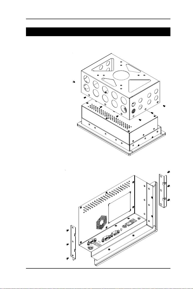
Mounting
Arm Mounting
Hook Mounting
6 P0715 Quick Installation
Page 7

Dimension
P0715 Quick Installation
Unit: mm
7
7
Page 8

OSD of Front Panel
8 P0715 Quick Installation
Page 9

Location of I/O Ports
Before starting to install software on your new Panel PC please spend some
time to find out the exact location of connectors and HDD (if pre-installed). The
front panel does not contain any indicators, switches, connectors or drive
access. All these are to be found on the left and right side and on the rear of the
system.
Default I/O
P0715 Quick Installation
9
9
Page 10

Connecting Peripherals
The user can use the I/O interfaces located at the backside of the chassis to
connect external peripheral devices, such as a mouse, a keyboard, a monitor,
serial devices or parallel printer etc. Before connection, make sure that the
computer and the peripheral devices are turned off.
Connecting an external CRT
P0715 has a 15-pin analog RGB interface connector located at the rear side of the chassis. As to
resolution, P0715 otputs 800 x 480 instead of 800
x 600, it won't display completely at first when
you connect the monitor.
External Serial Ports (COM1/2)
The P0715 logic board supports four onboard serial ports, all COM ports
supports RS-232.
The external COM1, COM2 are all D-SUB 9-pin
connectors. To connect any serial device, follow
the following instructions:
1. Turn off the Panel PC system and the serial
devices.
2. Attach the interface cable of the serial device to the 9-pin D-SUB serial
connector. Be sure to fasten the retaining screws.
3. Turn on the computer and the attached serial devices.
4. Refer to the serial device's manual for instruction to configure the operation
environment to recognize the new attached devices.
5. If the serial device needs specified IRQ or address, you may need to run the
CMOS setup to change the hardware device setup.
Speaker Jack
P0715 has one speaker jack.
10 P0715 Quick Installation
Page 11

LAN Port
P0715 provides one Intel 82562ET 100/10 Base-T
Ethernet (RJ-45) interface.
For network connection, follow the instructions
below;
1. Turn off the Panel PC system and the Ethernet hubs.
2. Plug in one end of cable of a 100/10 Base-T hub to the system's RJ-45 jack.
USB Ports
P0715 provides four external USB ports to connect
to external USB devices. USB ports and devices
are hotplug capable. Therefore any USB device can
be connected at all time without the need to power
down your system. Note that for many of these
devices you will first have to install proper device drivers before they can be
recognized by the system
PS/2 Keyboard/Mouse
P0715 provides two standard PS/2 keyboard/
mouse connectors located at the rear panel. If the
user would like to use AT keyboard, then an
adapter to connect the PS/2 KB to AT KB is
needed.
DC Power Input and Power Switch
One end of the power cable is fitted with a
standard power connector that connects to 4-pin
DC-In Jack.
To connect the system to power, follow the
following instructions :
1 Make the system power switched off.
2 Plug the circular connector firmly into the circular socket on the rear panel.
3 Connect the standard male plug to an electrical outlet.
4 For operation, power up the system.
P0715 Quick Installation
11
11
Page 12

Hardware Installation
HDD installation
1. On the back of P0715, locate the screws that secure the
rear case.
Use screw driver to remove the screws. Keep the screws
safely for later use.
Pull the baffle slightly upward the main unit until it is disen-
gaged from main unit.
2. Put the HDD into the drive bay and screw it on.
12 P0715 Quick Installation
Page 13

44 pin IDE Cable
2.5" HDD
Pin 1
Pin 1
Note: Beware of the directions when wiring HDD and IDE cable.
P0715 Quick Installation
13
13
Page 14

Panel PC Installation
1. In 2.4B or above Driver, choose Drivers & Utilities.
14 P0715 Quick Installation
Page 15

1.1 Select Panel Computing.
P0715 Quick Installation
15
15
Page 16

1.2 Select P0715.
16 P0715 Quick Installation
Page 17

1.3 Install All Drivers.
P0715 Quick Installation
17
17
Page 18

2. Install Touch Screen Driver.
18 P0715 Quick Installation
Page 19

4. Select Promote Touch Driver to install.
P0715 Quick Installation
19
19
 Loading...