

Page 1

OCPRF100 MP
Server System
Supporting Up To Eight Intel®
®
Pentium
III Xeon™ Processors
Technical Product Specification
Intel Order #753674-001
Revision 1.0
Page 2

OPRF100 MP Board Set Technical Product Specification
Revision 1.0
Revision History
Date Rev. Modifications
September, 1999 1.0 Initial release.
Disclaimers
Except as provided in Intel’s Terms and Conditions of Sale for such product s, INTEL DISCLAIMS
ALL LIABILITIES AND WARRANTIES (EXPRESS, IMPLIED OR OTHERWISE) ASSOCIATED
WITH THE INFORMATION CONTAINED WITHIN THIS DOCUMENT, OR FOR ANY PRODUCTS OR DEVICES REFERRED TO HEREIN, INCLUDING, WITHOUT LIMIT ATION, LIABILITY
FOR INFRINGEMENT OF ANY PROPRIETAR Y RIGHTS RELA TING TO THIS DOCUMENT, OR
ANY PRODUCTS OR DEVICES REFERENCED HEREIN, OR FOR THE IMPLEMENTATION
OF INFORMA TI ON IN THIS DOCUMENT INTEL IS NOT OBLIGATED TO PROVIDE ANY SUPPORT, INSTALLATION, OR OTHER ASSISTANCE WITH REGARD TO THESE DEVICES, NOR
ANY UPDATES, CORRECTIONS OR MODIFICATIONS TO THIS DOCUMENT OR THE
INFORMATION CONTAINED HEREIN.
THE INTEL
DARD COMMERCIAL USE ONLY. CUSTOMERS ARE SOLELY RESPONSIBLE FOR
ASSESSING THE SUITABILITY OF THE PRODUCT AND/OR DEVICES FOR USE IN PARTICULAR APPLICATIONS. THE REFERENCED INTEL PRODUCT IS NOT INTENDED FOR USE
IN CRITICAL CONTROL OR SAFETY SYSTEMS OR IN NUCLEAR FACILITY APPLICATIONS.
INTEL PRODUCTS ARE NOT INTENDED FOR USE IN MEDICAL, LIFE SAVING, OR LIFE
SUSTAINING APPLICATIONS.
Information in this document is provided in connection with Intel products. This document is provided “as is” with no warranties whatsoever. Intel specifically disclaims any implied or express
warranties of any kind whatsovever, associated with this document, including without limitation:
(i) liability for infrinement of any proprietary rights (including without limitation, any intellectual
property right), merch antability, fit ness for any particular purpose, or any warranty otherwise arising out of any product or testing proposal, speci ficat ion or sample; (ii) suf fici ency, reliability, accuracy, completeness or usefulness of same, and (iii) ability or sufficiency of same to function
accurately as a representati on of any standard. No license, express, implied, or otherwise, to
any intellectual property rights is granted by this document or by the sale of Intel products. Furthermore, Intel makes no commitment to update the information contained in this document or
any test report, provided that Intel may make changes to this document, the test reports, specifications and product descriptions at any t ime, without notice.
Third parties may have intell ectual property rights which may be relevant to this document and
the technologies discussed herein, accordingly the reader is advised to seek the advice of competent counsel, as required withhout obligation to Intel.
®
PRODUCT REFERRED TO IN THIS DOCUMENT IS INTENDED FOR STAN-
Page 3

OPRF100 MP Board Set Technical Product Specification
Revision 1.0
Only approved software drivers and accessori es that are recommended for the revision number
of the boards and system being operated should be used with Int el products . Please note that, as
a result of warranty repairs or replacements, alternate software and firmware versions may be
required for proper operation of the equipment.
The hardware vendor remains solely responsibl e for the design, sale and func ti onalit y of its product, including any liability arising from product infringement or product warranty.
The OPRF100 MP Board Set and the OCPRF100 MP Server System product may contain
design defects or errors known as errata that may cause the product to deviate fr om published
specifications. Current characterized errata are availab le on request.
2
I
C is a two-wire communications bus/protocol developed by Philips. SMBus is a subset of the
2
I
C bus/protocol and was developed by Intel. Implementations of the I2C bus/protocol or the
SMBus bus/protocol may require li censes from vari ous entiti es, includi ng Philips Electr onics N.V.
and North American Philips Corporation.
Copyright © 1999 Intel Corporation.
*Other brands and names are the property of their respective owners.
Page 4

OCPRF100 MP Server System Technical Product Specification
Revision 1.0
Table of Contents
Introduction........................................................................................................................... 1
Server System Chassis and Assemblies............................. .. .. ....................... ....................3
Front Panel Assembly....................................................................................................... 4
Peripheral Bay................................................................................................................... 4
Top Cover Assembly........................................ .. ...................... ..................... ....................5
Hot-plug PCI Access Door .......................................................................................... 6
Fan Bay............ ......................................................................... ........................................6
Front Panel Board.............................................................................................................8
Processor Mezzanine Board............................................................................................. 9
Processor Retention Mechanism ...................................................................................... 9
Profusion® Carrier Tray .................................................................................................. 11
Midplane As se m b l y................... .. ........................... .. ............. .. ... ............. .. ............. ... .. .... 13
I/O Carrier ....................................................................................................................... 14
Power Supply................................. .. .. ............. .. ........................... .. ........................... .. .. .. 16
OCPRF100 MP Server System Chassis..................... .. ..................... .. ........................... 16
System Over view ............. .. .. .............. .. ............. .. .. .............. .. ............. .. ... ............. .. ............. 17
Introduction..................................................................................................................... 17
External Chassis Features................................................................ .................... .. ........20
Front View of Ch a ss is .. ........................... .. ........................... .. .. ............. ... ................. 20
Rear View of Cha s sis. .. ........................... .. ............. ... .. ............. .. .............. .. ............... 2 3
Riser Board External I/O Connectors........................................................................24
Peripheral Bay........................................................................................................... 25
3.5-inch Use r- a cc e s sible Drive Bay .... ............. .. .. ............. ... .......................... .. ... ...... 26
5.25-inch User-accessible Drive Bay ........................................................................ 26
3.5-inch SCSI Hot-swap Drive Bays ....................................... .. .................... ............26
Internal Chas s is Features ........... ... .. ............. .. ........................... .. .......................... ... .. .... 27
Power Syste m . .. ... ............. .. .. .............. .. .......................... .. ........................... .. .. ......... 27
Cooling Syst e m ............... .. .. ............. ... .......................... .. ........................... .. .. ........... 29
PCI Hot-plug.... .. .............. .. .......................... ... .. ............. .. ........................... .. .. ........... 31
Server Management........................................................................................................34
Front Panel Controller...............................................................................................34
Baseboard Management Controller........................... ........................ .......................35
Hot-swap Con troller ............ ........................... .. .......................... ... .. ............. .. ........... 36
Expansion Support..........................................................................................................36
Specifications..................................................................................................................37
Environmental Specifications.................................................................................... 37
Physical Specifications.............................................................................................. 37
Cables and Connectors....................................... .................. ................................... .. ........39
Cables............................................................................................................................. 41
Connectors......................................................................................................................42
User-accessible I/O Connectors ............................................... ................................42
Serial Ports................................................................................................................ 43
Parallel Port............................................................................................................... 44
VGA Video Port.........................................................................................................44
Universal Serial Bus Interface................................................................................... 45
ICMB Connectors................. .............. .......................................................................46
i
Page 5

OCPRF100 MP Server System Technical Product Specification
Revision 1.0
Fan Connector .......................... ...................... ...................... .. ...................... .. ..........47
Peripheral Bay P o w e r C o n nec tor. .. .. .............. .. .......................... ... .. ............. .. ........... 47
Peripheral Bay Backplane Header............................................................................48
LED Board Connector................................... .. ........................ .. ........................ ........50
SCSI Connector........................................................................................................ 51
IDE Connectors.........................................................................................................52
Floppy Connectors...... ................ ................................................. .............................53
Power Supply .................................... .......................................................................... ........54
Mechanical Requirements............. ..................................................................................54
Mechanical Outline.................................................................................................... 54
Fan Requirements........................................................................ ................... ..........55
Interface Requirements................................................................................................... 55
AC Inlet Connector............................ ....................... ........................ .. .......................55
DC Output Connector(s) .......................... .................... .. .................... .. .....................55
Marking and Identification...............................................................................................56
LED Labeling............................... .. .. ........................ ............................................. .. ... 56
Internal Syst e m M ar k in g ........... .. .............. .. .. ............. .. ........................... .. .. .............. .. .... 56
Electrical Re q ui re m e n ts................................ .. ........................... .. .......................... ... .. .... 58
Efficiency................................................................................................................... 58
AC Input Voltage Specification......................................... .. .................... ...................58
AC Input Voltage Ranges........................... .. .......................................... ...................58
DC Output Specification............................................................................................ 59
Control Signals................................................................................................................ 62
Power Supply On (Input). ..........................................................................................62
AC OK Signal (Output).............................................................................................. 62
Power Good (Output). ...............................................................................................63
Power Supply Present Indicator (Output).................................................... ..............64
Predictive Failure Signal (Output).............................. .. .................. .. .................. .. ..... 64
Power Supply Failure Signal (Output)................................... .................. .. ................64
Power Supply Kill (Input)...........................................................................................65
Power Supply Field Replacement Unit Signals.........................................................66
LED Indicators........................................................................................................... 66
Fan Speed Control............................................................................. ...................... .. ..... 67
Environmental Requirements............................................................... ...........................67
Physical Environment................................................................................................ 67
Thermal Protection............................................ ................. ................ .......................67
Regulatory Agency Requirements..................................................................................67
System Softw a r e . ............. .. ........................... .. .. ............. .. ........................... .. .. .............. .. ....68
System Hardware............................................................................................................ 69
Processors ................................................................................................................ 69
Profusion® Chip Set.................................................................................................. 70
I/O Subsystem................................................................ .. .................... .................... .70
Intelligent Platform Management Bus............................................................... ........71
Industry Standards..........................................................................................................71
ACPI..........................................................................................................................71
Boot Devices a nd P e ri ph e rals. . .. ............. .. ............. ... ............. .. ............. ... .. ............. .. 7 2
Management.............................................................................................................73
Configuration............................................................................................................. 73
BIOS Setup Utility ........................................................................................................... 74
Main Menu ...................... .. .......................... ... .......................... .. ... ............. .. ............. 75
ii
Page 6

OCPRF100 MP Server System Technical Product Specification
Revision 1.0
Advanced Menu ........................................................................................................ 78
Security Men u ................. .. .. ............. ... .......................... .. ........................... .. .. ........... 82
Server Menu.... .. ... ............. .. ........................... .. .. ............. .. ........................... .. .. ......... 83
Boot Menu.............. .. ........................... .. .. ............. .. ........................... .. ...................... 85
Exit Menu ........ .. .............. .. .. ............. ... .......................... .. .. .............. .. ........................ 86
Flash Utility...................................................................................................................... 86
Regulatory Specifications............................................ ................................... ................... 88
Safety Compliance............. ... .. ............. .. ... ............. .. ........................... .. .......................... 88
Electromagnetic Compatibility.........................................................................................88
CE Mark .......................................................................................................................... 88
Electromagnetic Compatibility Notice (USA)........................ .. .................... .. ...................89
Electromagnetic Compatibility Notices (International).....................................................89
Peripheral Bay Backplane Board ......................... ........................................... .. ................90
Peripheral Bay Backplane Overview...............................................................................90
Architectural Overview .............................................................................................. 91
Placement Dia g ra m.. ............. ... .. ............. .. ........................... .. .......................... ... .. .... 91
Deviations from SAF-TE Specification...................................................................... 91
Functional Description.....................................................................................................91
Hot-swap Connectors................................................................................................ 92
SCSI Interface . .......................................................................................................... 92
LVD/SE Acti ve T e rmination........ .......................... .. .............. .. .. ............. ... ............. .. .. 9 2
Power Contr ol ...... .. .......................... ... .. ............. .. ........................... .. .. ............. ... ...... 92
FET Short Protection................................................................................................. 93
Microcontroller........................................................................................................... 93
LED Arrangement .................................. .. .. ......................... .. ............................ ........93
IPMB (I2C bus).......................................................................................................... 94
Temperature Sensor ................................................................................................. 94
Serial EEPROM ........................................................... .. .. ...................................... ...94
Board Functi o n s......... ............. .. ........................... .. .. ............. .. ........................... .. .. ......... 94
Reset......................................................................................................................... 94
Microcontroller........................................................................................................... 95
SCSI Controller.........................................................................................................97
LVDS SCSI Termination .................................... ...................... .......................................97
LVDS Termination.................................................... ................... .................. ............97
Single Ended T e rm i n a tio n.................................... .. ... ............. .. ........................... .. .... 98
Programmab le Lo g ic................. .. ........................... .. .. ............. ... .......................... .. ... ...... 98
Memory Map ........... ... ............. .. ........................... .. .......................... ... .. ............. .. ........... 98
Memory Map ..... ... ............. .. ........................... .. .......................... ... .. ............. .. ........... 98
I/O Ports.................................................................................................................. 101
Signal Descriptions....................................................................................................... 103
Power Good Signal.................................................................................................103
CONN_EN_L........................................................................................................... 103
CONN_SDI.............................................................................................................. 103
CONN_SDO............................................................................................................ 103
CONN_MODE......................................................................................................... 104
CONN_SCLK .......................................................................................................... 104
Electrical, Mechanical Specifications.................. ..................... .................................... .104
Connectors..............................................................................................................104
Peripheral Bay Board (Chassis Side).................... ..................... .................................... .111
Introduction................................................................................................................... 111
iii
Page 7

OCPRF100 MP Server System Technical Product Specification
Revision 1.0
Mechanical Description................................................................................................. 111
Board Layou t.............. .............. .. .......................... .. .............. .. .. ............. ... ............. .. 11 1
Front Panel..................... .. .. ..................... .............................................. ........................ .......... 113
Introduction................................................................................................................... 113
Board Overv ie w.... ............. .. .. .............. .. ............. .. .. .............. .. ............. .. ... ............. .. 1 1 3
Functional Description...................................................................................................114
Microcontroller......................................................................................................... 114
Memory Maps ...... .. ............. .. ........................... .. .. ............. ... .......................... .. ....... 114
Memory ................................................................................................................... 118
Front Panel Indicator LEDs..................................................................................... 122
Front Panel LCD .....................................................................................................123
System Power......................................................................................................... 123
Reset....................................................................................................................... 124
Speaker...................................................................................................................126
Fan Control ............................... .............................................. ................................126
ICMB and COM2 Redirection....................................................... .. .. .......................126
Front Panel Push Buttons.......................................................................................129
I2C Interface s............. .............. .. .. ............. .. ... ............. .. ........................... .. ............. 13 0
Miscellaneous ......................................................................................................... 132
Appendix A: Glossary ................................. .................. .. .................. .. .................. ................133
Appendix B: References .......................................................... .......................................... ... 137
iv
Page 8

OCPRF100 MP Server System Technical Product Specification
Revision 1.0
1. Introduction
This document provides an overview of the OCPRF100 MP server system and includes information on cabling, connectors, power supply, and regulatory requirements.
Document Structure and Outline
This document is organized into ten chapters:
Chapter 1: Introduction
Provides an overview of this document.
Chapter 2: Server System Chassis and Assemblies
Provides an overview of the chassis hardware.
Chapter 3: System Overview
Provides an overview of the system hardware.
Chapter 4: Cables and Connectors
Describes the cables and connectors used to interconnect the OPRF100
board set and the server system components.
Chapter 5: Power Supply
Describes the specifications for the 750-W power supply.
Chapter 6: OCPRF100 MP Server Software
Provides an overview of the system software.
Chapter 7: Regulatory Specifications
Describes system compliance to regulatory specifications.
Chapter 8: Peripheral Bay Backplane Board
Describes the features and functional ity of the peripheral bay backplane
board.
Chapter 9: Peripheral Bay Board (Chassis Side)
Describes the design of the peripheral bay board (chass is si de).
Chapter 10: Front Panel
Describes the design and external interface of the OCPRF100 MP server
system front panel.
1
Page 9

OCPRF100 MP Server System Technical Product Specification
Revision 1.0
This page intentionally left blank.
2
Page 10

OCPRF100 MP Server System Technical Product Specification
Revision 1.0
2. Server System Chassis and Assemblies
This chapter describes the chassis and assembly pieces that reside within the chassis. This
chapter is divided into the following areas:
• Front panel assembly
• Peripheral bay
• Top cover assembly
• Fan bay
• Front panel board
• Processor mezzanine board
• Processor retention mechanism
®
• Profusion
carrier tray
• Midplane assembly
• I/O carrier assembly
• Power supply
• OCPRF100 MP server system chassis
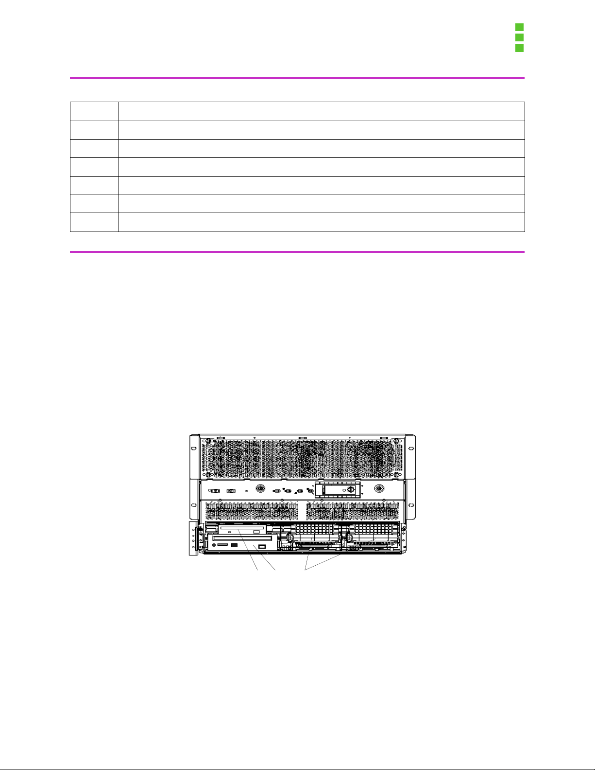
Figure 2-1: OCPRF100 MP Server System Chassis
3
Page 11

OCPRF100 MP Server System Technical Product Specification
Revision 1.0
2.1 Front Panel Assembly
The front panel assembly consists of an upper and lower bezel. The bezels serve as cosmetic
pieces only, and can be integrator specific. Finger grips are provided to make it easy to remove
the bezels. Removing the bezels exposes the front side of the fan bay, the front panel controller
(FPC) switches (power, reset, and nonmaskable interrupt (NMI)), as well as the indicator lights
(power indicator, predictive power supply failure, predictive fan failure, and hard drive failure).
From this location, the hot-swap hard drives and/or t he peripheral bay may be removed from the
system.
Figure 2-2: Front Panel
2.2 Periphera l Ba y
The peripheral bay is defined to be a customer specif ic, removable device capable of supporting
a floppy drive, dual hot-swap hard drives, and a low-voltage differential SCSI (LVDS) or single
ended SCSI device. The integrator has the option of defining the size and capacity of the hard
drives, as well as deciding whether the LVDS will support CD-ROM, tape, or other device. A single ended SCSI channel is provided for support of a SCSI device, should the integrat or so desire.
The peripheral bay is designed to be easily added and removed from the front of the server by
removing the front cover and four mounting screws. The peripheral bay connects to the
OPRF100 I/O carrier and the power supply via a blind mate board connector and cabli ng. The
blind mate board is located in front of the midplane board, on the left side of the server (when
viewing the server from the front). The blind mate connector connects to the peripheral bay’s
LVDS board upon insertion, thus connecting all peripheral devices to the I/O carrier.
The peripheral bay will contain a 1.4 MB floppy dr ive, space for a half-height 5 ¼ inch device
(typically a CD-ROM), and has two bays designed to accommodate either a 1-inch or a 1.6-i nch
SCA hard drive.
4
Page 12

OCPRF100 MP Server System Technical Product Specification
Revision 1.0
Figure 2-3: Peripheral Bay
2.3 Top Cover Assembly
The top cover assembly is released by removing the two retaining screws located on the top
toward the front (E in Figure 2-4: Hot-plug PCI Access Door) , between the fan bay assembly and
the top cover assembly marked with the AC caution icon. The cover slides towar d the rea r of the
server and then lifts straight up off of the ser ver cha ssi s, expos ing t he upper port ion o f the ser ver
for maintenance, upgrades, or adding components.
Tape and sheet metal work were done to the sides of the top cover assembly to provide a better
gripping surface for easier removal and replacement of the top cover assembly. Care should be
taken to avoid damage to the electromagnetic compatibility (EMC) gasket material on the ins ide
of the top cover.
5
Page 13

OCPRF100 MP Server System Technical Product Specification
Revision 1.0
2.3.1 Hot-plug PCI Access Door
The hot-plug PCI access door is released by removing the two ret ai ning screws (A i n Figure 2-4:
Hot-plug PCI Access Door) located on the top, middle area of the server . The cover sli des toward
the rear of the server and lifts straight up off of the server chassis, exposing the hot-plug PCI
cards.
The hot-plug PCI access door is designed to maintain a flush surface with the top cover assembly, such that a vacuum-based hoist may be used during the assembly proc ess.
A
B
Figure 2-4: Hot-plug PCI Access Door
2.4 Fan Bay
The fan bay is a mechanical structure designed to contain six separate 120-mm cooling fans.
These fans operate at a nominal voltage of 8.4 Vdc (2% toleran ce) under normal conditions.
Each fan produces a tachometer- based output to indicat e the revolu tions per minute (RPM) read ing of the motor . Should a fa n’s t achometer out put drop below a predefined normal range of operation, the FPC notifies the server management soft ware that a fan has entered into th e predictive
fan failure condition. At t his point, the f ans will operat e at an elevated volt age of approximatel y 12
Vdc.
6
Page 14

OCPRF100 MP Server System Technical Product Specification
Revision 1.0
The fan bay will operate at high speed on the following conditions:
• Internal temperature has reached an elevated, but noncritical set-point.
• Ambient temperate exceeds 30°C.
• A fan has entered into the predictive failure mode.
• A fan has failed.
If the FPC detects a fan entering the predictive fan failure mode, the speed of all of the fans will
be increased to maintain thermal requirements. The individu al fans within the fan bay are all hotswappable, meaning that they can be removed and inserted while the server is running. Server
management will identify that a fan has either fail ed or has entered into the predictive failure
mode. In both cases, the fan should be repl aced immediately. Removal of a fan is accompli shed
by opening the fan bay cover and pulling (A) to lift the malfunctioning fan (B) out through the top
of the server as shown in Figure 2-5: Fan Bay. The malfunctioning fan shoul d then be repl aced
with a new fan. The system will detect that the fan has been replaced, and as long as no other
thermal violations are currently occurring, the fan will resume operation at the reduced speed.
A
B
Figure 2-5: Fan Bay
OM07304
7
Page 15

OCPRF100 MP Server System Technical Product Specification
Revision 1.0
Fans are installed with th e connector on t he left side fac ing down. The cavities i n the f an bay are
keyed to prevent a fan from being install ed backwards.
The fan bay is installed after the Profusion carrier assembly is installed and completely seated
into the midplane. The fan bay is lowered into the chassis unti l it is seated on the flanges of the
Profusion tray. Two screw holes, one on each side, should now be aligned on the sides of the
chassis. Insert screws into these holes to secure the fan bay into the chassis.
The fan bay cover is hinged at the rear and captivated by the system top cover assembly. Tabs in
the rear of the fan bay cover engage with slots on the rear of the fan bay to secure the cover in
normal operation. The fan bay cover is secured by one noncap tive screw loca ted on the center of
the cover’s front flange. Remove the screw, slide the cover forward and lift. The cover remains
open while servicing the fans.
To remove the fan bay from the chassis, it is first necessary to re move all in dividual fans from the
fan bay . The fans plug direct ly into the front p anel board and must be removed before the fan bay
can be lifted out.
The fan bay cover provides critical electr omagnetic interference (EMI) containment. To avoid
electrical interference with adjacent equipment, close and secure the fan bay cover during normal system operation.
In systems with only one processor mezzanine board, an air baffle needs to be installed on the
vacant side of the CPU retention cage to ensure proper cooling for the installed processo rs.
2.5 Front Panel Board
The FPC board provides power and monitors the tach ometer readings from each individual fan
within the fan bay. The FPC also serves as a platform for the server contr oller switches, and supports circuitry required for server management.
The FPC board is located on the same plane as, and connects to the Profusion carrier board via
a connector. Both the FPC and Profusion carrier board are mounted to the topsi de of the Profusion carrier tray. On the left front edge of the FPC board are three push but ton switch es—power,
reset, and NMI. Each switch plunger has a small black cap on it s end, which is necessar y for the
proper operation of the buttons on the front bezel.
To install an FPC board, tilt the board forward as shown in Figur e 2-6: Fr ont Panel Board I nst al la tion, and insert the switches into the openings on the front flange of the Profusion carrier tray.
Lower the back of the board onto the standoff s on the tr ay. Align the board-to-board connectors
and slide the board back to engage the connectors. Secure with nine screws. Reverse this operation to remove the board.
8
Page 16

OCPRF100 MP Server System Technical Product Specification
Revision 1.0
Figure 2-6: Front Panel Board Installation
2.6 Processor Mezzanine Board
The base configuration of an OCPRF100 MP server system consists of a single processor mezzanine board. The processor mezzanine board is designed to support one to four Pentium
®
III
Xeon™ processors, providing power, ground and other connections to the processor(s) and to
the Profusion carrier. The processor mezzanine board incorporates integrated volt age regulator
modules (VRMs) to supply the internal voltage requirements to the processor cartridge.
2.7 Processor Retention Mechanism
The processors and termination cards are secured in their respective slots by means of the processor retention mechanism. The processor retention mechanism holds up to eight processors
or termination cards. In th e ev ent th e server is populat ed wit h o nly a singl e proces sor mezzan ine
card, the processor retention mechanism will be popul ated with a total of four contiguous processors and/or terminators.
9
Page 17
OCPRF100 MP Server System Technical Product Specification
Revision 1.0
A
Captive Screw
B
Hold-down
Strap
C
Air Baffle
Figure 2-7: Processor Retention Mechanism
A processor/termination card p air is secured with a hold-down strap (B) that hooks into the back
of the retention mechanism and is fastened at the front with two capt ive screws (A). (The retention strap is for a pair of process ors or terminat ors). See Fi gure 2-7: Pro cessor Retent io n Mechanism.
The processor retention mechanism is secured t o the mezzanine boar ds with the sa me four l ock
bars that secure the mezzanine boards to the Profusion ca rrier board. In the event the server is
populated with only a single process or mezzanine car d, an air baffle (C) must be install ed on the
vacant side of the processor retention mechanism.
To remove or add a processor, first relea se the capti ve screws (A), then swi ng the reten tion strap
(B) upward. Remove the terminator card, and install the processor. Replace the retention strap
(B), and tighten the captive screw (A).
Due to space restrictions in the system, the Profusion carrier tray assembly must be removed
from the chassis to install and service the mezzanine boards. The fan bay assembly must be
removed prior to removing the Profusion carrier tray.
10
Page 18

OCPRF100 MP Server System Technical Product Specification
Revision 1.0
2.8 Profusion® Carrier Tray
The processor mezzanine boards plug into the Profusi on carrier tray. The Profusion carrier tray
serves as a platform to provide power and signals to the processor mezzanine board, route signals through the 1008-pin grand connector, and carry components of the Profusion chip set.
Components of the Profusion chip set th at reside on the Profu sion carrie r are the memory acces s
controller (MAC) and the data interface buffer (DIB).
The Profusion chip set allows a five-por t system data bus, with concur rent switching t aking place.
This is a requirement for an efficient eight-way server. The Profusion chip set will suppor t two
processor buses (each bus containing between one and four processors), two memory buses,
and a single I/O bus. All of the buses operate at 100 MHz for maximum throughput. The data is
routed through the Profusion tray, into the midplane connector for distribution to the appropriate
source (memory carriers or the I/O carri er).
B
Lock Bars
C
Lock Bar
Release Handle
A
Alignment Tabs
Figure 2-8: Profusion® Carrier Tray
Assembly of the Profusion carrier board, and mezzanine boards to the Profusion carrier tray, is
performed outside the cha ssis. To start the assembly, install the Profusion carrie r to the Profusi on
tray by aligning the eight tabs on the tray with the slots on the board (See Figure 2-8 (A)). Next,
install the FPC board by passing the FPC switches through the switch openings in the tray and
11
Page 19

OCPRF100 MP Server System Technical Product Specification
Revision 1.0
then moving back into place for connection to the Profusion carrier board. Place the four lock
bars over the protruding tabs and onto the Profusi on carrier board (B). The release handles of
the lock bars (C) should be pointed to the outsid e of the board and t hey should be in t he unlocked
position. Place the first mezzanine board on the left side of the Profusion carrier board, oriented
so the mezzanine board does not extend over the 1008-pin grand connector on the Profusion
carrier board. Press down in the center of the mezzani ne board until it is seated down onto the
lock bars. If the configurat ion call s for a second mezzani ne board, i nstall it on the r ight side of the
Profusion carrier board by following th e same steps as described for the first board.
2
2
1
1
3
3
Figure 2-9: Profusion® Carrier Tray
Lower the processor retent ion mechanism onto t he mezzanine board(s) , aligning the hooks on it s
bottom with the slots in the mezzanine board(s). The processor retention mechanism should be
oriented such that the center notch for the coher ency filters is facing forward. Engage the fou r
lock bars by pushing in on their ends until they click. The Profusion carrier tray assembly is now
ready for installation in the chassis.
To install the Profusion carrier tray assembly into the chass is, set the tray on t he tray support s on
the inside walls of the chassis and slide it towared the midplane. The tray and chassis have selfaligning features to help guide the tray as it approaches the grand connector on the midplane.
When the connectors are within approximateil y 1” from connect ing, check under the Profusion
carrier tray for proper engagement of the center supports. The insertion/extraction levers (3) on
the side of the tray should be tilted forward as the connectors approach each other. As the con-
12
Page 20

OCPRF100 MP Server System Technical Product Specification
Revision 1.0
nectors begin to engage, rotate the levers back until the connectors are fully engaged. Levers
should be in an upright or near upright position. Secure the tray and the processor retention
mechanism to the sides of the chassis with screws (1) and (2) as indi cated in Figure 2-9.
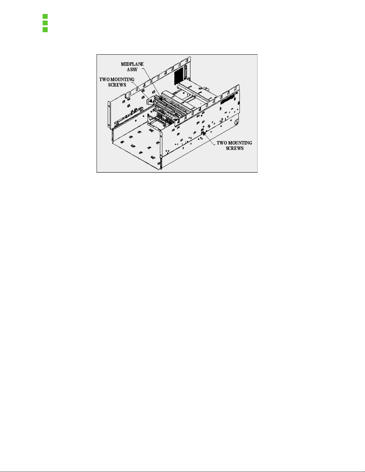
2.9 Midplane Assembly
The midplane assembly serves as an i nterconnect bet ween the power suppli es, memory boa rds,
Profusion carrier, and the I/O carrier. With the exception of limited server management and field
replaceable unit (FRU) components, the mi dplane assembly s erves merely as an interconnect ion
device, routing the signa ls between the boards , whi le maintaining the signal integr i ty requi re d for
the 100-MHz buses.
Figure 2-10: Midplane Assembly
The midplane assembly is inst alled into the OCPRF100 MP server system chass is by rotating the
assembly about two ali gnment s tru ctures. T he assembly i s secur ed b y a tot a l of fo ur scr ews, t wo
screws are located on each side of the system. All four screws must be removed to extract the
midplane assembly. The tab on the midplane assembly is used to manage the cables between
the I/O baseboard and the peripheral blind-mat e board.
13
Page 21
OCPRF100 MP Server System Technical Product Specification
Revision 1.0
Figure 2-11: Midplane Assembly Installed in System
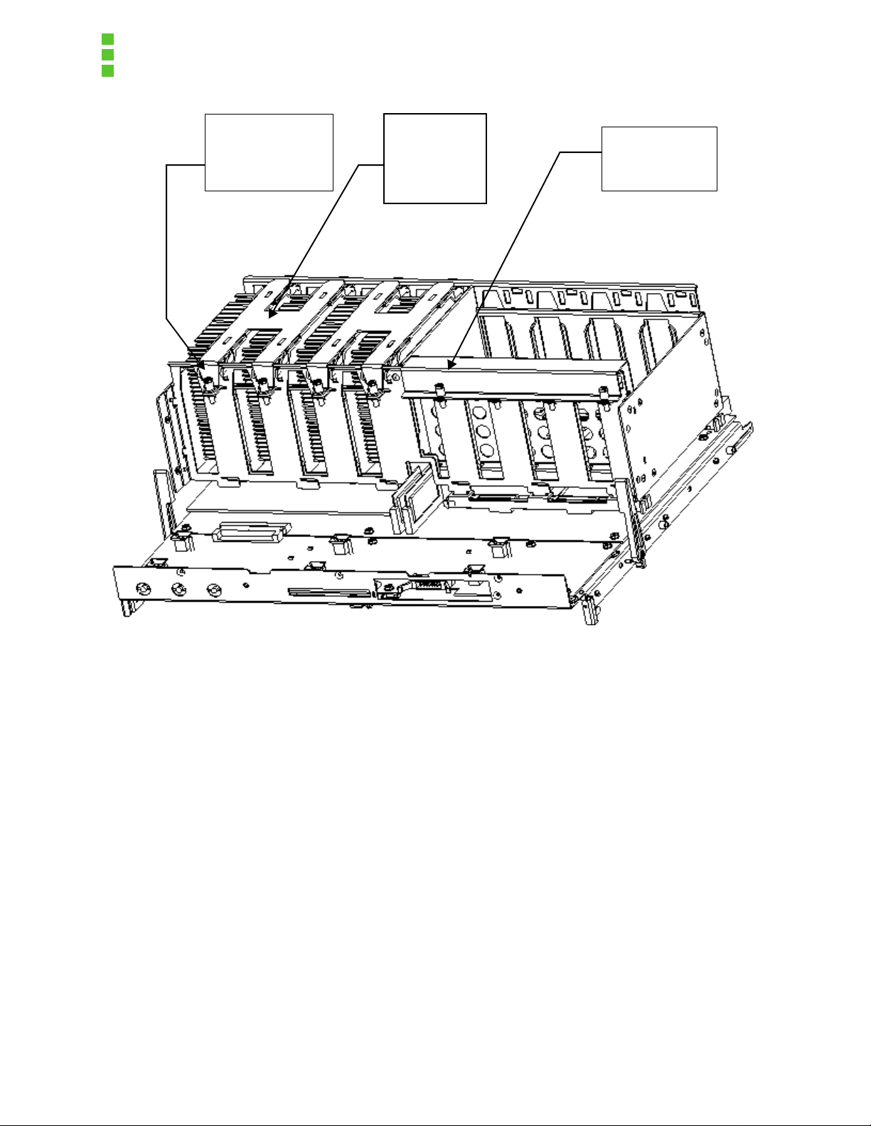
2.10 I/O Carrier
The I/O carrier is the i nterf ace that con nects the I/O port of t he Profu sio n chi p set to the foll owing :
• Ten hot-swappable PCI slots (four of which support 66-MHz transactions).
• Legacy connector (video, keyboard, serial, parallel, USB, and Intelligent Chassis Man-
agement Bus (ICMB) ports).
• Dual LVDS.
• Internal IDE buses, floppy disk, disk drives, and SCSI connectors for peripheral support.
The PCI hot-plug (PHP) I/O carrier, legacy connector, LVDS connectors, ICMB board, and
enhanced PCI hot-plug board are assembled onto the I/O carrier tray. The PCI hot-plug base
shield is assembled and mounted over the PHP I/O board, and secured by six screws. The PHP
slot dividers snap onto the PHP base shield.
14
Page 22

OCPRF100 MP Server System Technical Product Specification
Revision 1.0
Figure 2-12: I/O Carrier Tray
The I/O carrier tray features tabs on the base of the tray that engage into slots on the horizontal
members in the chassis. Lower the tray from the top of the system and slide the tray toward the
center of the chassis using the two insert/extract handles located on the back of the tray. Secure
the I/O carrier tray to the chassis with the four screws located on the sides and back of the chassis.
Figure 2-13: Installing the I/O Carrier Tray
15
Page 23
OCPRF100 MP Server System Technical Product Specification
Revision 1.0
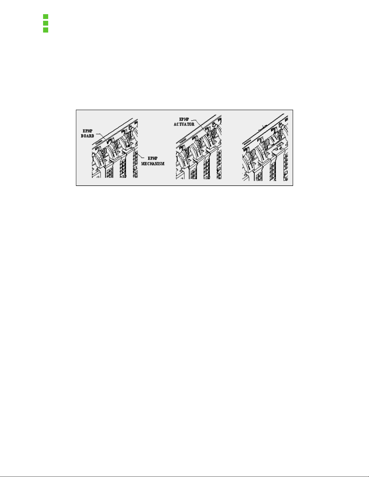
The PHP mechanism is a rotating part that actuates a switch located on the PHP board. There
are four light emitting diodes (LEDs) per sl ot--tw o can be viewed fr om the rear of the system and
two from inside the system. Once the LED shows which slot is powered down, the PHP mechanism can be depressed on the PHP actuator and the mechanism can be rotated out of place to
remove the PCI card. Once the new PCI card is installed, rotate the PHP mechanism back into
place to activate the switch and secure the PCI card.
Figure 2-14: PHP Mechanism
2.11 Power Supply
The OCPRF100 MP server system power supply operates at 208 - 220 Vac, or 100 - 115 Vac is
rated at 750 watts, and is designed to be hot-swappable, with a 2+1 redundancy factor. Each
power supply has indicators showing correct operation, failure, and predictive failure. A power
supply displaying the predicti ve fail ure LED still will oper ate corect ly, but needs to be sent out for
repair as quickly as p ossible. The predictiv e failure feature is designed t o warn the operat or of an
impending power supply failure.
2.12 OCPRF100 MP Server System Chassis
The system chassis is the rack-mount chassis used in the system. The system chassis is
designed to house all of the components listed above within a 7Ux 32” (+/-) deep space, and
mount in a 19-inch rack. The chassis itsel f is 28” deep with the extra 4” to account for cable management. The chassis was engineered to provide easy access to per form maintenance,
upgrades, add memory, and add or remove PCI cards.
The functional server weighs between 120 and 140 pounds, depending on internal configurations. The chassis is designed to provide adequa te thermal cooling of all devices within an ambient temperature of 10° to 40°C, while maintaining noise levels below 57 dB. If the ambient
temperature exceeds 30°C, the fans in the fan bay will sw itch to high speed, cooling the system
to operational values. Server management will log that a thermal excursion has occurred. Several internal heat sensors will monitor the temper ature at key point s inside the server. Should any
of these sensors indicate that the temperature has exceeded a critical thermal set-point, server
management will log the event, and the server will be shut down gracefull y, according to user
setup.
16
Page 24

OCPRF100 MP Server System Technical Product Specification
Revision 1.0
3. System Overview
This chapter describes the features of the OCPRF100 MP server system chass is.
System Features
Table 3-1 provides a list and brief description of the features of the OCPRF100 MP server system, which utilizes the OPRF100 board set.
Table 3-1: OCPRF100 MP Server System Feature List
Feature Description
Upgradeability
PCI hot plug The chassis with the OPRF100 board set supports 10 64-bit PCI hot-plug
Compact, high-density system The system size is a 7U (12.25-inch) rack-mount server.
Redundant power The system supports three 750-W power supplies in a redundant (2 + 1)
Redundant cooling Six system fans in a redundant (5+1) configuration cool the upper system
Modular peripheral bay The peripheral bay supports one floppy disk drive, one 5.25-inch half-
Front panel liquid cr ys t al displ ay
(LCD)
Intelligent Management Platform Initiative (IPMI) compliant
The system can be upgraded to future processors within the Pentium
Xeon™ processor fa mily.
slots (four at 66 MHz, six at 33 MHz).
configuration.
(CPU and I/O). Three internal power supply fans cool the lower system
(memory, peripheral ba y, and p ower sup plies ) in a red undan t confi guratio n
when the power supply configuration is redundant (2+1).
height device, and two 3.5-inch by 1.0- or 1.6-inch hot-swappable LVDS
SCSI hard drives.
A two line LCD provides the system status.
Intelligent Platform Management Bus (IPMB) for intrachassis communication is provided. Emergency management port (EMP) is used for remote
management.
®
III
3.1 Introduction
The scalable architecture of the OCPRF100 MP server syste m supports symmetrical multiprocessing (SMP) and a variety of operating systems (OS). The server provides 10 PCI card slots.
The Profusion carrier contains connectors for installing up to eight Pentium III Xeon processors
packaged in single-edge contact cartridges (SECC). Each of the two memory carriers supports
17
Page 25

OCPRF100 MP Server System Technical Product Specification
Revision 1.0
up to 16 GB of error correcti on code (ECC) PC-100 comp atible regi stered DIMMs. The I/O c arrier
contains four 66-MHz and six 33-MHz 64-bit hot-swap PCI slots, I/O ports, and various controllers.
Figure 3-1: OCPRF100 MP Server System Chassis with Peripheral Bay shows an isometr ic view
of the chassis with the peripheral bay installed.
Figure 3-1: OCPRF100 MP Server System Chassis with Peripheral Bay
Figure 3-2: OPRF100 Board Set/System Board Locations withi n Server Chassis displays t he layout of the OPRF100 board set with respect to location within the chassis. The Profusion carrier
and I/O carrier are mounted hor izont ally, with the Profusion carrier toward the front of the ch assis
and the I/O carrier immediat ely behind at the r ear of th e chassis . The midplan e di stri butes power
and signal connections to al l boards. T he midplane resi des between the Pr ofusion car rier and the
I/O carrier, and interconnects these carriers with the memory carriers and system power supplies. The front panel resides in front of the Profusion c arrier in the same plane and provides the
user interface, system management, and cooling syst em power and control.
18
Page 26

Profusion Carrier
Front Panel
OCPRF100 MP Server System Technical Product Specification
Revision 1.0
I/O Riser Board
I/O Carrier
Power Supplies
Memory Carriers
Midplane
Figure 3-2: OPRF100 Board Set/System Board Locations within Server Chassis
The peripheral bay mounted at the lower front of the chassis sup ports a 3.5-inch floppy drive, a
half-height 5.25-inch device (e.g., CD-ROM) and two 3.5-inch by 1.0- or 1.6-inch hot-swap hard
drives. SCSI drives in the hot-swap hard drive bays can be hot-swapped without shutting down
the server.
The chassis supports up to three hot-swap, redundant power supplies in a 2+1 configuration.
These supplies provide redundant and hot-swappable cooling to the memor y carri ers an d per ipherals when the power supplies are i n a redundant conf iguration. A cover plate for the un occupied
power supply location is supplied for sys tems without redundancy, and should be used to provide
adequate cooling and EMI shielding.
The system design provides a hot-swap, redundant (5+1) cooling system for the Profusion and I/
O carriers. Basic controls and indicators are located on the front panel.
The front bezel can be customized for integrators to meet their industrial design requirements.
The front bezel contains openings to provide adequate cooling for the chassis components and
access to the peripherals.
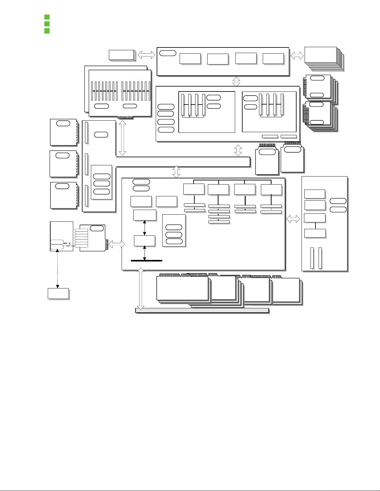
Figure 3-3: OCPRF100 MP Server System Chassis Bloc k Diagram shows a block diagram of t he
server system.
19
Page 27
OCPRF100 MP Server System Technical Product Specification
Revision 1.0
FRU
Hot Swap
Power
Supply
FRU
Hot Swap
Power
Supply
FRU
Hot Swap
Power
Supply
Intelligent
Chassis
Management
Bus PBA
icmb
icmb
Intelligent
Chassis
Mgt. Bus
kbd
mouse
serial
serial
parallel
video
icmb
Temp
FRU
Power
Distribution
Volt
Temp
Status
FRU
I/O riser
card
LCD
Memory Carrier
(16 DIMMs)
Midplane
IPMB,
I2C
FRU
I2C,
PIIX4E SMBus
Volt
Temp
BMC flash
BMC
SMIC
Profusion*
Carrier
BMC RAM
ISA Bus
FRU
FRU
Temp
Volt
Status
SEEPROM
LEDs
Slot Type-2
Slot Type-2
IPMB, I2C, PIIX4E SMBus
PB64
BMC
SDR
SEL
FRU
Slot Type-2
Processor
Mezzanine
33MHz
PCI
FPC
Front Panel
Temp
FRU
Slot Type-2
Board
PB64
I/O Carrier
IPMB, I2C
33MHz
PCI
FPC flash
IPMB, I2C
Temp
FRU
Processor
Mezzanine
Board
PB64
66MHz
PCI
FPC RAM
Slot Type-2
Slot Type-2
FRU
Cache
Coherency
Board
(optional)
PB64
All slots are
64-bit &
Hot- Plug
Slot Type-2
66MHz
PCI
Slot Type-2
FRU
Cache
Coherency
Board
(optional)
IPMB
FAN
FAN
FAN
FAN
FAN
Temp
Pentium®III
Xeon™
Processor
FRU
Temp
Pentium®III
Xeon™
Processor
FRU
LVDS Disk Backplane
HSC flash
HSC RAM
HSC
SCSI I/F
Drive Slots
Temp
FRU
external
64b PCI
Add In Card
PCI Hot-Plug LED/Switch Board
64b PCI
Add In Card
Add In Card
Figure 3-3: OCPRF100 MP Server System Chassis Block Diagram
3.2 External Chassis Features
3.2.1 Front View of Chassis
The front bezel of the server has two main user-accessible areas:
Front panel liquid crystal display (LCD), switches and indicato rs.
Replaceable media bays—floppy drive and 5.25-inch half-height bay.
20
64b PCI
64b PCI
Add In Card
Page 28

OCPRF100 MP Server System Technical Product Specification
A B C D E F G H
Revision 1.0
I J K L M N
O P Q
Figure 3-4: Front View of Chassis with No Bezel
Table 3-2: System Features – Front
Item Feature Description
Front Panel Controls and Indicators
A Power switch When pressed, turns the DC power inside the server on or off.
B Reset switch When pressed, resets the server and causes the power-on self-test
(POST) to run.
C NMI switch When pressed, causes a nonmaskable interrupt (NMI). This switch is
recessed behind the front panel to prevent inadvertent activation. (The
switch must be pressed with a narrow tool.)
D Power (LED) (green) When continuously lit, indicates the presence of DC power in the server.
The light emitting diode (LED) goes out when the power is turned off or
when the power source i s disrupted. Wh en flashin g, indicate s the syst em is
in advanced configuration and power interface (ACPI) sleep mode.
E Power fault LED (yellow) When continuously lit, indi cates a power suppl y failu re. When fla shing , indi-
cates a 240 VA overload shutdown and power control failure.
21
Page 29

OCPRF100 MP Server System Technical Product Specification
Revision 1.0
Table 3-2: System Features – Front
F Fan fault LED (yellow) When lit, indicates either a fan failure, or that a predictive fan failure has
been detected in the server.
G Drive fault LED (yellow) When continuously lit, indicates an asserted fault status on one or more
hard disk drives in th e hot-swap bay. When flas hi ng, in dic ate s drive rebuild
in progress.
H Front panel LCD Displays information about processor type and failure codes.
(Items I through L on are control buttons for the CD-ROM, and the location may vary from manufacturer to manu-
facturer.)
3.5-inch Floppy Diskette Drive Descriptions
M Activity LED When lit, indicates the drive is in use.
N Ejector button When pressed, ejects the diskette.
Status LEDs for SCSI Drives in Hot-swap Bays
O Drive power LED
(green)
P Drive activity LED
(green)
Q Drive fault LED (yellow) When continuously lit, indicates an asserted fault status on one or more
When continuously lit, indicates the presence of the drive and that drive is
powered on.
When flashing, indicates drive activity.
hard disk drives in the hot-swap bay. When flashing, indicates that drive
rebuild is in progress.
22
Page 30

3.2.2 Rear View of Chassis
OCPRF100 MP Server System Technical Product Specification
Revision 1.0
A
E
F
G
H
CB
D
I
Table 3-3: System Features – Rear
Item Description
A PCI add-in board slots.
B External LVDS connector.
C ICMB connectors in/out.
D I/O riser board.
E AC input power connector.
F Three power supplies.
Figure 3-5: Rear View of Chassis
23
Page 31

OCPRF100 MP Server System Technical Product Specification
Revision 1.0
Table 3-3: System Features – Rear
G PWR LED (green) – power condition – refer to Chapter Power Supply for details.
H FAIL LED (yellow) – failure condition – refer to Chapter Power Supply for details.
I PR_FL LED (yellow) – power supply fan predictive failure – refer to Chapter Power Supply for details.
3.2.3 Riser Board External I/O Connectors
Figure 3-6: Riser Board External I/O Connectors
Table 3-4: Riser Board External I/O Connectors
Item Description
A. Serial port 1 (COM1), 9-pin RS-232 connector.
B. Parallel port, 25-pin bidirectional connector.
24
Page 32
OCPRF100 MP Server System Technical Product Specification
Table 3-4: Riser Board External I/O Connectors
C. USB ports 0 (upper) and 1 (lower).
D. Super VGA compatible, 15-pin video connector.
E. Serial port 2 (COM2), 9-pin RS-232 connector.
F. PS/2-compatible keyboard port.
G. PS/2-compatible mouse port.
H. ICMB port, SEMCONN* 6-pin connector.
I. ICMB port, SEMCONN 6-pin connector.
3.2.4 Peripheral Bay
An optional peripheral bay provides the foll owing:
Revision 1.0
• One 3.5-inch floppy drive bay
• One 5.25-inch user-accessible drive bay for removable media
• Two 3.5-inch by 1.0- or 1.6-inch hot-swap bays for SCSI SCA hard disk drives
A B C
Figure 3-7: Chassis Drive Bays
25
Page 33

OCPRF100 MP Server System Technical Product Specification
Revision 1.0
Table 3-5: I/O External Connectors
Item Bay Description
A 3.5-inch bay 3.5-inch floppy drive.
B 5.25-inch half-height bay 5.25-inch half-height peripheral drive.
C 3.5-inch by 1.0- or 1.6-inch bays Two hot-swap capable hard drives.
3.2.5 3.5-inch User-accessible Drive Bay
The system ships from the factory witho ut the peripheral bay installed.
3.2.6 5.25-inch User-accessible Drive Bay
The system ships from the factory witho ut the peripheral bay installed.
Note: Installation of hard disk drives in the 5.25-inch user-accessible bay is not recommended
due to cooling and EMI constraints.
3.2.7 3.5-inch SCSI Hot-swap Drive Bays
Two 3.5-inch hot-swap capable bays support eit her 1.0- or 1.6-inch high SCA SCSI hard disk
drives. These bays are accessible following removal of the lower bezel section. The wide LVDS
SCSI hot-swap backplane provides industry st andard 80-pin SCA-2 connectors for two drives.
Two wide/fast-20 SCSI III SCA type hard disk drives can be install ed in these bays. The wide
LVDS SCSI hot-swap backplane is designed to accept drives that consume up to 28 watts of
power and run at a maximum ambient temperature of 50°C (112°F).
Extruded aluminum drive carriers with integral heat sinks that accommodate 3.5-inch wide by
either 1.0- or 1.6-inch high driv es a re required as part of the hot-swap implementation. The carrier is attached to the drive with four fast eners, and is retai ned in the chassis by a locki ng handle.
The LEDs below each drive display individual drive status. There are three LEDs for each drive:
a power on (green) LED; an activity (green) LED; and a fault (yellow) LED. A fault LED on the
front panel board also indicates a fault on these drives.
Note: Because all hard drives have different cooling, power and vibration characteristics, Intel
will not validate hard drive types in the sys tem chassis. Refer to the OCPRF100 MP Server Sys-
tem Validation Summary document for a list of these drives.
26
Page 34

OCPRF100 MP Server System Technical Product Specification
Revision 1.0
3.3 Internal Chassis Features
3.3.1 Power System
Three 750-W supplies in a standard configuration provide the modular power system for the system.
The power system may be configured with three power supplies (2+1) for power redun-
dancy, or with two supplies in a nonredundant configuration.
a row at the rear bottom of the chassis.
A single AC power cord provides power to the daisy-
chained supplies.
When the server is configured with three power supplies, the user can hot swap a failed supply
without affecting system functionality.
The midplane provides power distribution of the internal power system with minimal active cir-
cuitry.
The power distri bution circui try report s quantity and l ocation of the i nstall ed power supplies
through I
2
C* server management.
Two 750-W, 208-Vac supplies are capable of handling power requirements for the OPRF100
board set and peripherals.
For the OPRF100 board set, this includes eight Pentium II I Xeon pro-
cessors, 32 GB of memory and two 1.6-inch hard drives.
The power supplies are mounted in
The Profusion carrier provides he aders f or two processor mezz anine boar ds, each pr oviding f our
slots for Pentium III Xeon processors. Each mezzanine board has six integrated VRM 8.3 compatible voltage converters. The converter input is +12 Vdc from the power supply. Each Pentium
III Xeon processor core has its own converter. One converter provides power for a pair of Pentium III Xeon processor L2 caches.
The total power requ ir ement for t he OPRF100 board s et exceeds the 24 0 VA energy hazard limit
that defines an operator accessible area. As a result, only qualified technical individuals should
access the processor, memory, and non-hot-plug I/O carrier areas while the syst em is energized .
Refer to Chapter Power Supply Power Suppl y of this document for detailed power specifications.
Table 3-6: System Power Budget – Current (A) and Power (W)
OCPRF100 MP Server
System Power Budget
Board Spec Units +3.3 V +5 V +12 V -12 V +5
Units +3.3 V +5 V +12 V -12 V +5
VSB
VSB
Power
Power
I/O Carrier Min. Load Adc 0.20 0.70 0.00 0.20 0.65 9.81
Max. Load Adc 7.99 45.20 5.00 1.20 0.75 330.52
Max. Step Load Adc 2.00 12.17 4.50 0.25 0.10
27
Page 35

OCPRF100 MP Server System Technical Product Specification
Revision 1.0
Table 3-6: System Power Budget – Current (A) and Power (W)
Profusion® Min. Load Adc 4.60 0.75 0.25 0.000 0.00 21.93
Carrier w/ Max. Load Adc 12.00 1.50 46.00 0.000 0.00 599.10
Mezzanines Max. Step Load Adc 2. 00 0.75 18.00
Front Panel Min. Load Adc 0.00 0.05 2.00 0.001 0.10 24.76
Max. Load Adc 0.00 0.23 5.40 0.010 0.25 67.32
Plugs into Max. Step Load Adc 0.18 0.10 0.001 0.15
Profusion Carrier
Memory Carrier 1 Min. Load Adc 1.20 0.00 0.00 0.000 0. 00 3.96
Max. Load Adc 23.00 0.00 0.00 0.000 0.00 75.90
Max. Step Load Adc 8.00
Memory Carrier 2 Min. Load Adc 0.00 0.00 0.00 0.000 0. 00 0.00
(Note: 2) Max. Load Adc 23.00 0.00 0.00 0.000 0.00 75.90
Max. Step Load Adc 8.00
Peripherals Min. Load Adc 0.00 0.70 0.25 0.000 0.00 6.50
(SCSI Backplane) Max. Load Adc 0.00 4.50 5.99 0.000 0. 00 94.38
Max. Step Load Adc 0.90 5.40
Midplane Min. Load Adc
Max. Load Adc 0.01 0.01 0.01 0.20
Total min. load Adc 6.00 2.20 2.50 0.20 0.75 66.96
Total max. step load Adc 20.00 14.00 28.00 0.25 0.25
Max. step di/dt A/uS 0.50 1.00 0.60 0.10 0.10
Total max.
load
Total load
power:
1243.32 W 217.8 257.2 748.80 14.52 5 1243.3
Adc 66.00 51.44 62.40 1.21 1.00
28
2
Page 36

OCPRF100 MP Server System Technical Product Specification
Table 3-6: System Power Budget – Current (A) and Power (W)
Total power (includes 2% distribution loss) 1268.1
Notes: 1. There is no 240 VA protection circuit in the OCPRF100 MP server system.
2. Minimum load for second memory carrier is zero; assumes no carrier is installed.
3.3.2 Cooling Syst em
3.3.2.1 Description
There are two independent cooling subsystems:
The upper system, encompassing the front p anel, Profusion carrier, and I/O carrier.
Revision 1.0
9
The lower systems, encompassing the memory carrie rs, peripheral bay, and power supplies.
Air flows in through the bezel and exhausts out the rear of the chassis.
Cooling system redundancy to the upper system is provided by the 5+1 redundant fans at the
front top of the system. All systems come with redundant cool ing for the upper area in standard
factory configuration with six upper system fans. Each fan provides tachometer sign al output to
the front panel t o indicate a fan f ailure. There may be time limit restrict ions on th e service t ime for
fan and PCI hot-plug card replacement.
Cooling system redundancy of the lower system is provided by the 2+1 system power supplies.
Each power supply fan provides t achometer si gnal output. A power supply f an failure is indicat ed
at the front panel as a predictive power supply failure. There may be time restrictions on the service time for power supply hot swap replacement.
3.3.2.2 Redundancy and Ambient Temperature Control
3.3.2.2.1 System Fans
The front panel provides either of two fan input voltages to the system fans. Under normal ambient room conditions (less than 30°C), the front panel supplies 8.4 Vdc to the system fans. When
a system fan fails or when the room ambient temperature exc eeds 30°C, the fan input voltage is
increased to 12 Vdc. Following a room temperature excursion a bove 30°C, the fan voltage does
not change back to 8.4 Vdc unti l the room temperatur e drops below 28°C a nd all syst em fans are
operational.
3.3.2.2.2 Power Supply Fans
The power supply fans are controlled independently by each supply. The ambient temperature
sensed at the inlet to each supply is used as the input to a cont rol cir cuit, which conti nuously var -
29
Page 37

OCPRF100 MP Server System Technical Product Specification
Revision 1.0
ies the fan input voltag e. At 28°C ambient temperature, the fan input volt age is 8.0 ± 0.5 Vdc, and
at 35°C, the fan input voltage is 13.5 Vdc.
3.3.2.3 Cooling Summary
The system fans are sized to provide cooling for up to eight Pentium III Xeon processors. The
power supply fans are sized to cool both fully populated SDRAM board sets, two hot-swap hard
drives, and for maintaining power supply functi on under a full load condit ion . The coolin g system
is designed using a worst case analysis with no margin under a single fan failure (system or
power supply fan) condition. The environmental conditions are summarized in Section Specifications. Figure 3-8: OCPRF100 MP Server System Cooling s ummarizes the c ooling provide d to the
system components when system and power supply fans are operating with 12 Vdc input. The
lower fan speed settings were chosen to meet acoustic and thermal requi rements.
70 CFM (12 Vdc Input)
70 CFM (12 Vdc Input)
70 CFM (12 Vdc Input)
150 CFM
(Maximum w/ all
power supply
fans functioning)
System Fan System Fan System Fan
CFM/
HDA
Profusion*
Carrier
Pentium (R)
III Xeon (TM)
Pentium III
Xeon
Processor
System Fan System Fan System Fan
(16 DIMMs)
Memory Carrier
Memory Module
(16 DIMMs)
12
Hot-Swap Hard Drive
Backplane
Carrier
PB64
PB64
Midplane
I/O
64b PCI Add-in Card
PB64
PB64
750 W Power Supply
750 W Power Supply
750 W Power Supply
64b PCI Add-in Card
64b PCI Add-in Card
64b PCI Add-in Card
PS Fan
PS Fan
PS Fan
210 CFM (12
50 CFM (13.5 Vdc fan
input voltage)
50 CFM (13.5 Vdc fan
input voltage)
50 CFM (13.5 Vdc fan
input voltage)
Vdc)
30
Figure 3-8: OCPRF100 MP Server System Cooling
Page 38

OCPRF100 MP Server System Technical Product Specification
Revision 1.0
3.3.3 PCI Hot-plug
3.3.3.1 Description
PCI hot plug (PHP) is the concept of removing or inserting a standard PCI adapter card from a
system without stopping the software or powering down the system as a whole.
“Hot Replace” means the user can replace a PCI card with an identical card. The re placement
card will use the same PCI resources assigned to the previous card. OS support is required for
this function .
“Hot Add” means the user can add a PCI card to a previousl y unoccupied slot. The system BIOS
needs to reserve PCI resource space for the added adapt er card upon boot.
“Hot Upgrade” means to replace an existing adapter card with a new version of the card and/or
driver. A hot upgrade is not actually a unique operation. It is implemented as a hot removal followed by a hot addition.
3.3.3.2 Hardware Components
Intel has licensed the hardware technology and methods for the implementation of PHP, which
conform to the PCI Hot-plug Specification. The basic components are:
• Power cycling and reset generation hardware that complies wit h the PCI Local Bus Spec-
ification, Rev. 2.1.
• Bus isolation switches to physically disconnect the PHP capable card from the PCI bus
(these switches are located on the I/O carrier between each PHP PCI card).
• Indicators (LEDs), located on the PHP LED/switch board, provide service personnel with
positive slot identificat ion (these LEDs are vi sible when viewed fr om above the I/O carrier,
and can be seen from the rear of the system through holes in the chassis).
• Electromechanical hardware to prevent accidental insertion/removal from a live sl ot (a
PHP switch is provided for each slot; when disengaged this switch immediately removes
power from that slot. Normal slot power down should be through the control utility
• Protection hardware to isolate the live components of the system from the card being
inserted/removed (a mechanical barrier prevents access to the I/O carrier and Profusion
carrier components, and is present between PCI cards; each PHP PCI connector is limited to 240 VA).
• A controller element which c ontrols th e above hardwar e and provides an inter face for sys tem softwar e .
3.3.3.3 Software Components
The main software components for a PHP system are:
Hot-plug User Interface
• Provides user with access to the hot-plug control panel
31
Page 39

OCPRF100 MP Server System Technical Product Specification
Revision 1.0
• Receives user input and sends requests to the service layer
• Displays the status of the PCI slot
• Provides user with access to PHP functions that may be available through multiple inter-
faces
Hot-plug Service
• Provides communication between the user interface a nd the hot-pl ug controller driver and
is responsible for configuring, loading, and unloading the adapter driver component
• Puts the system into a quiescent state through the hot-plug adapter card by making standard system calls
• Provides communication to the hot-plug control ler
• Reports status to the hot-plug user interface
Hot-plug Driver
• Communicates a hot-plug request from the system’s service layer
• Provides a software bridge to the PCI hot-plug hardware
• Drives the hot-plug controller
BIOS
• Supplies initialization of the hot-plug hardware components
• Provides DIMM ID monitoring and presence detection
• Provides Advanced Configuration and Power Interfac e (ACPI) table generation
Adapter Drivers
• For Windows NT* 4.0, changes need to be made to standard miniport drivers.
• For SCO* UnixWare* Version 7.01, the driver must be DDI-8 compliant.
• For Novell* NetWare* Version 5.0, the driver must comply with the NWPA 2.32 or ODI
3.31 specifications.
3.3.3.4 PCI Hot Plug Mechanical Implementation
. The mechanical retention solution includes the following items:
• LED PC board
• Cable between LED board and the I/O carrier baseboard
• Rocker mechanism
• Plastic card guide/retention mechanism to secure the rear of each installed PCI card
32
Page 40

OCPRF100 MP Server System Technical Product Specification
Revision 1.0
• A 240 VA protective shield on the I/O baseboard and the plastic dividers between PCI
slots
The LED PC board contains both the green and amber LEDs, as well as the switch that controls
the PCI slot power. These items will no longer reside on the I/O carrier baseboar d. This LED
board is mounted in the I/O tray directly abov e where the PCI cards were previously sc rewed into
the tray ledge. The LEDs can be seen from both inside and outside of the chassis. Each switch
hangs down off of the LED board so that it can be activate d by the rocker mechanism as it is
folded into the chassis. See Figure 3-9: Rocker Mechanism.
Figure 3-9: Rocker Mechanism
The rocker mechanism activates the slot power switch as it enters the I/ O tray. The rocker can be
released only from within the chassis. This is to prevent unintentional power down of PCI slots
when the system is powered up and the chassis has not yet been pulled out of the rack. The
rocker also acts as a retenti on mechanism for t he PCI card. An additional rete ntion mechani sm at
the back edge of the PCI card is currently being developed.
The opposite end of the PCI card is held in place by a plastic, snap-in, locking card guide. The
guide, installed on the center support bracket, has a built in retention mechanism that secures
the top-rear edge of the PCI card. (See Figure 3-10.)
33
Page 41

OCPRF100 MP Server System Technical Product Specification
Revision 1.0
Figure 3-10: PCI Card Retention Mechanism
Revised non-hot plug, hot plug, and t op cover s are re quir ed to ac commodate t he ad diti onal hard ware used in this enhanced solution.
3.4 Server Management
The server system management architecture features several management controllers, which
autonomously monitor server status and provide the interface to server management control
functions. The controllers communicat e via an I
Platform Management Bus (IPMB).
The functions of each controller are summarize d in the following sect ions. The firmwar e of all the
controllers is field upgradeable, using the Server Management Firmware Update Utility. Refer to
the OCPRF100 MP Server Management External Architecture Specific ation for more details.
3.4.1 Front Panel Controller
The FPC on the OCPRF100 MP server system chassis front panel board manages the front
panel operations. Since this controller is resp onsible f or system power contr ol, it is powered from
2
C-based serial bus referred to as the Intelligent
34
Page 42

OCPRF100 MP Server System Technical Product Specification
Revision 1.0
the +5 V standby output of the power supply. The FPC takes part in implementing the following
system functions:
• Power and rese t s w it ch in te rfaces
• Fan failure detection
• Chassis FRU inventory
• System hard reset generation
• System power fault indication
• ICMB bridge device
• Emergency management port (EMP)
• LCD interface
3.4.2 Baseboard Management Controller
The baseboard management controller (BMC) on the OPRF100 board set I/O carrier provides
server management monitoring capabilities. Associated with the BMC is a flash memory that
holds the operation code and the BMC configuration defaults. The various ser ver management
functions provided by the BMC are listed below.
• Baseboard voltage monitoring
• Processor voltage monitori ng
• Processor voltage ID (VID) monitoring
• Processor presence detection
• Processor internal error (IERR) and thermal trip monitoring
• Fault resilient booting (FRB)
• Processor disable control
• Watchdog timer
• Periodic system management interrupt (SMI) timer
2
C master controller
• I
• Private management bus interface
• System management software (SMS) and SMM IPMB message receiver
• Event message receiver
• System event log management and access
• Sensor data record (SDR) repository management and access
• Processor NMI monitoring
• Processor SMI monitoring
• Time-stamp clock
• POST code log
35
Page 43

OCPRF100 MP Server System Technical Product Specification
Revision 1.0
• Secure mode, video blank, and floppy write protect
• Front panel NMI monitoring
• Software front panel NMI generation
3.4.3 Hot-swap Controller
The hot-swap controller (HSC) on th e LVDS SCSI hot-swap backplane is connected to other system boards via the IPMB. The HSC provides server management information through both the
IPMB and the SCSI Accessed Fault-Tolerant Enclosures (SAF-TE). SAF-TE is an industry standard for communicating drive and slot status.
The HSC:
• implements the SAF-TE command set accessed through SCSI;
• provides an IPMB path for drive pre sence, dri ve fa ult status, backplane temperatur e, and
fan failure;
• controls the fault lights and drive power on the OCPRF100 MP server system chassis
hot-swap backplane;
• monitors the power distribution backplane for power supply status; and
• controls drive power on and off, facilitating hot-swapping of drives.
3.5 Expansion Support
Table 3-7: OCPRF100 MP Server System Expansion Support summarizes the expansion support provided by the server system.
Table 3-7: OCPRF100 MP Server System Expansion Support
Quantity Type
10 64-bit PCI hot-plug expansion b us slots
2 Single connector attachment (SCA-2) SCSI hard disk drive bays
1 5.25-inch half-height drive bays
1 External LVDS connecto r
32 72-bit SDRAM PC-100 registered DIMM module so ckets (16 per memory module)
36
Page 44

OCPRF100 MP Server System Technical Product Specification
Revision 1.0
3.6 Specifications
3.6.1 Environmental Specifications
The system will be tested to the environmental specifications as indicated in Table 3-8.
Table 3-8: Environmental Specifications Summary
Environmental Feature Specification
Operating temperature 10° to 35°C (50° to 95°F). See Altitude exception.
Nonoperating temperature -40°C to 70°C (-40°F to 158°F).
Altitude 0 to 3048 m (0 to 10000 ft.). Note: Maximum ambie nt temperat ure is
linearly derated between 1520 m (5000 ft.) and 3050 m (10000 ft.)
by 1°C per 305 m (1000 ft.).
Operating humidity 85%, noncondensing at 40°C (104°F).
<33°C (91.4°F) wet bulb at 40°C (104°F) without peri phe rals.
Nonoperating humidity 95%, noncondensing at +55°C (131°F).
Safety UL 1950, CSA 950, IEC 950, TUV EN60 950, NEMKO.
Emissions Certified to FCC Class B; tested to CISPR 22B,
EN 55022, and registered with VCCI.
Immunity Verif ied to compl y with EN 50082 -2.
Electrostatic discharge (ESD) Tested to ESD levels up to 20 kilovolts (kV) air discharge without
physical damage as per the Intel
Acoustic Sound pressure: < 57 dbA at ambient temperatures.
< 28°C measured at bystander positions in operating mode.
Sound power: < 6.5 BA at ambient temperatures.
< 28°C in operating mode.
®
environmental test specification.
3.6.2 Physical Specifications
Table 3-8 describes the physical specifications of the system.
37
Page 45

OCPRF100 MP Server System Technical Product Specification
Revision 1.0
Table 3-8: Dimensions and Weight
Specification Value
Height 31.12 cm (12.25 inches, 7u)
Width 44.45 cm (17.5 inches)
Depth 71.12 cm (28.0 inches)
Weight 51.4 kg (113 lbs.) minimum configuration
63 kg (140 lbs.) maximum configuration
Required front clearance 10 inches (inlet airflow <35 °C / 95 °F)
Required rear clearance 8 inches (no airflow restriction)
Notes: 1. The system weight listed above is only an approximation and can vary depending
on number of peripherals and add-in cards in the system.
2. The system dimensions exclude the power supply handles for depth.
38
Page 46

OCPRF100 MP Server System Technical Product Specification
Revision 1.0
4. Cables and Connectors
This chapter describes cables and connectors that interconnect various components of the
OCPRF100 MP server system.
The block diagram in Figure 4-1: OCPRF100 Server Syst em Interconnect Diagram shows cabl es
that connect the boards used in the OCPRF100 MP server system.
39
Page 47

OCPRF100 MP Server System Technical Product Specification
Revision 1.0
FAN FAN FAN FAN FAN FAN
CBL,PWR,AC
(External Interface)
AC
Inlet
Filter
Hot-Swap
Power Supply
Hot-Swap
Power Supply
Hot-Swap
Power Supply
36 Pin Berg*
Connector
36 Pin Berg
Connector
36 Pin Berg
Connector
LCD
Memory
DIMMs)
Carrier
(16
Midplane
Memory
Carrier
(16
DIMMs)
LCD Power
14 Pin & 2 Pin
CBL,LCD
System
Interconnect
System
Interconnect
100 MHz
I/O Carrier
LVDS Ch 1
Front panel
Profusion*
Carrier
3 pin WOL
Header
80 Pin SCA
Style Connector
6x24x3
HDM Connector
6X24X3
HDM Connector
PHP
Connector
4 pin Hot-Swap
Fan Connectors
Pentium(R) III
Xeon(TM) or Term.
Pentium III
Xeon or Term.
Pentium III
Xeon or Term.
Pentium III
Xeon or Term.
Pentium III
Xeon or Term.
Pentium III
Xeon or Term.
Pentium III
Xeon or Term.
Pentium III
Xeon or Term.
ICMB
Cable
I/O Riser board with
Keyboard, Mouse,
(2)USB, (2)Serial &
Parallel Connectors
(External Interface)
PHP LED Board
Mezzanine
Mezzanine
ICMB Board
40
External LVDS
SCSI Interface
Power Connector
68 Conductor
SCSI Cable
Floppy
IDE Cable
40 Conductor
5-1/4 CD-ROM Half
Height (Single Device
Option Only)
Floppy
IDE
Floppy
Cable
LVDS Ch 2
40 Conductor
IDE Cable
34 Conductor
Floppy Cable
Conductor
68 Conductor
SCSI Cable34 Conductor
Peripheral Bay
Backplane
40
Figure 4-1: OCPRF100 Server System Interconnect Diagram
240 Pin Connector
Hot-Swap
Hard Drive
Backplane
80-Pin SCA2
Connectors
1
1
Ultra2 SCSI Drives
2
Page 48

OCPRF100 MP Server System Technical Product Specification
Revision 1.0
4.1 Cables
Table 4-1 through Table 4-3 list flat ribbon cables and wire b undl es that are used i n the as sembly
of the OCPRF100 MP server system.
Table 4-1: Flat Ribbon Cables
Number
Quantity
of Pins Type Path
1 68 Wide SCSI cable w/VHDCI
interconnect modul e (sol id
core)
1 68 Wide SCSI cable (solid core) From the PHP I/O carrier to the peripheral bay back-
1 40 IDE cable (long) From the I/O carrier to the peripheral bay backplane.
1 40 IDE cable (short) From the LVDS backplane to the IDE CD-ROM.
1 34 Floppy drive cable (long) From the I/O carrier to the peripheral bay backplane.
1 34 Floppy drive cable (short) From the LVDS backplane to the floppy drive.
1 40 Flat ribbon cable (LED board) From the I/O board to the PHP LED board
Routes from the PHP I/O carrier to a panel cut in the
back of the system, where a VHDCI interconnect module can link an external VHDCI cable with the internal
SCSI devices.
plane.
Table 4-2: Wire Bundles
Number
Quantity
1 4 Power cable F rom the L VDS bac kplane
of Pins Type Path
to the CD ROM and floppy
drive.
1 20 Power cable From the midplane to the
peripheral bay backplane.
Table 4-3: Optional Cable
Number
Quantity
1 50 Narrow SCSI cable From the LVD S backplane to the 5-1/4" device bay , if an
of Pins Type Path
IDE device is not present.
41
Page 49

OCPRF100 MP Server System Technical Product Specification
Revision 1.0
4.2 Connectors
The following section describes the signals and pinouts for various connectors on the OPRF100
board set.
4.2.1 User-accessible I/O Connectors
4.2.1.1 Keyboard and Mouse Ports
These identical PS/2-compatible ports share a common housing.
The top port is for the mouse
and the bottom port is for the keyboard.
Table 4-4: Keyboard and Mouse Ports
Mouse Keyboard
Pin Signal Pin Signal
1 MSEDAT (mouse data) 1 KEYDAT (keyboard data)
2 No connection 2 No connection
3 GND (ground) 3 GND (ground)
4 FUSED_VCC (+5 V) 4 FUSED_VCC (+5 V)
5 MSECLK (mouse clock) 5 KEYCLK (keyboard clock)
6 No connection 6 No connection
42
Figure 4-2: Keyboard or Mouse Connector
Page 50

OCPRF100 MP Server System Technical Product Specification
Revision 1.0
4.2.2 Serial Ports
The I/O carrier provides two stacked RS-232C serial ports (the top one is COM1 and the bottom
one is COM2).
rately with the configuration contr ol provided on the I/O carrier.
The COM2 serial port can be used either as an emergency management port or as a normal
serial port.
server management RS-232 connection to the FPC on the front panel board.
level of emergency management through an external modem.
monitored by the FPC when the system is in a powered down (standby) state.
information, see the Emergency Management Port v1.0 Interface External Product Specification.
They are D-subminiature 9-pi n connectors. Each serial port can be enabled sepa-
As an emergency management port, COM2 is used as a communication path by the
This provides a
The RS-232 connection can be
For additional
Table 4-5: Serial Port Connectors
Pin Signal
1 DCD
2RXD
3TXD
4DTR
5GND
6DSR
7RTS
8CTS
9RIA
Figure 4-3: Serial Port Connector
43
Page 51

OCPRF100 MP Server System Technical Product Specification
13
OM00933A
1
25 14
Revision 1.0
4.2.3 Parallel Port
The IEEE 1284-compatible parallel port—used primarily for a printer—sends data in par allel for-
mat.
The parallel port is accessed through a D-subminiature 25-pin connector.
Table 4-6: Parallel Port Connector
Pin Signal Pin Signal
1 STROBE_L 14 AUFDXT_L (auto feed)
2 Data bit 0 15 ERROR_L
3 Data bit 1 16 INIT_L (initialize printer)
4 Data bit 2 17 SLCTIN_L (select input)
5 Data bit 3 18 GND (ground)
6 Data bit 4 19 GND
7 Data bit 5 20 GND
8 Data bit 6 21 GND
9 Data bit 7 22 GND
10 ACK_L (acknowledge) 23 GND
11 BUSY 24 GND
12 PE (paper end) 25 GND
13 SLCT (select)
4.2.4 VGA Video Port
The video port interface is a standard VGA compatible 15-pin connector. Onboard video is supplied by a Cirrus Logic* GD5446 PCI video controller with 2 MB of onboard video DRAM.
44
Figure 4-4: Parallel Port Connector
Page 52

OCPRF100 MP Server System Technical Product Specification
5
OM00936A
1
15 11
610
Table 4-7: Video Connector
Pin Signal
1 Red (analog color signal R)
2 Green (analog color signal G)
3 Blue (analog color signal B)
4 No connection
5 GND (video ground, shield)
6–8 GND (video ground, shield)
9 No connection
10 GND (video ground)
11–12 N o co nne cti on
Revision 1.0
13 HSYNC (horizontal sync)
14 VSYNC (vertical sync)
15 No connection
Figure 4-5: Video Connector
4.2.5 Universal Serial Bus Interface
The built-in USB ports permit the direct connection of two USB peripherals without an external
hub.
If more devices are required, an external hub can be connect ed t o eit her o f the buil t-in port s .
Table 4-8: Dual USB Connector
Pin Signal Description
A1 VCC Overcurrent monitor line port 0.
45
Page 53
OCPRF100 MP Server System Technical Product Specification
Revision 1.0
Table 4-8: Dual USB Connector
A2 DATAL0 Differential data line paired with DATAH0.
A3 DATAH0 Differential data line paired with DATAL0.
A4 GND Ground potential.
B1 VCC Overcurrent monitor line port 1.
B2 DATAL1 Differential data line paired with DATAH1.
B3 DATAH1 Differential data line paired with DATAL1.
B4 GND Ground potential.
A1 A4
B1 B4
Figure 4-6: Dual USB Connector
4.2.6 ICMB Connectors
The ICMB connector provides external access to the ICMB. This makes it possible to externally
access chassis management functions, alert logs, post-mortem data, etc.
mechanism for chassis power control.
allow daisy chained cabling.
Additional information about ICMB can be found in the External
The server provides two SEMCONN* 6-pin connectors to
Intelligent Management Bus Bridge External Program Specification.
Table 4-9: ICMB Connector
Pin Signal
1 No connection
2 No connection
3 B (negative)
It also provides a
4A (positive)
5 No connection
6 No connection
46
Page 54

4.2.7 Fan Connector
Table 4-10: Fan Connectors (J1A1,J9A1,J10A1)
OCPRF100 MP Server System Technical Product Specification
Revision 1.0
1 6
Figure 4-7: ICMB Connector
Pin Signal
1Ground
2 VCCFAN
3Ground
4 FAN_Tach
4.2.8 Peripheral Bay Power Connector
Table 4-11: Peripheral Bay Power Connector
Pin Signal Color
1+12V Yellow
2GND Black
3+12V Yellow
4+5V Red
5GND Black
6+5V Red
7GND Black
8SCL Green
9GND Black
10 PWR_Good White
11 +12V Yellow
47
Page 55

OCPRF100 MP Server System Technical Product Specification
Revision 1.0
Table 4-11: Peripheral Bay Power Connector
12 GND Black
13 +12V Yellow
14 +5V Red
15 GND Black
16 +5V Red
17 GND Black
18 SDA Light Blue
19 GND Black
20 RST_I2C_L Violet
4.2.9 Peripheral Bay Backplane Header
Table 4-12: Peripheral Bay Backplane Header (240 position)
Column A B C D E
1 RESET(1) GND DD8 (4) GND GND
2 DD7 (3) GND DD9 (6) GND FD_DENSEL
3 DD6 (5) GND DD10 (8) GND GND
4 DD5 (7) GND DD11 (10) GND N/C
5 DD4 (9) GND DD12 (12) GND GND
6 DD3 (11) GND DD13 (14) GND FD_DRATE0
7 DD2 (13) G ND DD14 (16) GND GND
8 DD1 (15) G ND DD15 (18) GND FD_INDEX_L
9 DD0 (17) G ND GND DIOW (23) GND
10 DMARQ (21) GND GND GND FD_MTR0_L
11 GND GND GND DIOR (25) GND
12 GND GND RESERVED (32) GND FD_DR1_L
13 IORDY (27) G ND PDIAG (34) GND GND
14 DMACK (29) GND DA2 (36) GND FD_DR0_L
15 INTRQ ( 31) GND CS0 (37) GND GND
48
Page 56

OCPRF100 MP Server System Technical Product Specification
Revision 1.0
Table 4-12: Peripheral Bay Backplane Header (240 position)
16 DA1 (33) GND DA0 (35) GND FD_MTR1_L
17 DASP (39) GND CS1 (38) GND FD_MSEN1
18 GND GND GND GND FD_DIR_L
19 GND GND FD_STEP_L GND GND
20 FD_WDATA_L GND GND GND FD_WGATE_L
21 GND GND FD_TRK0_L GND FD_MSEN0
22 FD_WPROT_L GND GND GND FD_RDATA_L
23 GND GND FD_HDSEL_L GND GND
24 FD_DSKCHG_L GND S35 (-DB 12) S2 (+DB 13) S37 (-DB 14)
25 +12V +12V S1 (+DB 12) S36 (-DB 13) S3 ( +DB 14)
26 +12V +12V S38 (-DB 15) S5 (+DB P1) GND
27 +12V +12V S4 (+DB 15) S39 (-DB P1) GND
28 +12V +12V S41 (-DB 0) S8 (+DB 1) S43 (-DB 2)
29 +12V +12V S7 (+DB 0) S42 (-DB 1) S9 (+DB 2)
30 +12V +12V S44 (-DB 3) S11 (+DB 4) S46 (-DB 5)
31 +12V +12V S10 (+DB 3) S45 (-DB 4) S12 (+DB5)
32 +12V +12V S47 (-DB 6) S14 (+DB 7) S49 (-DB P)
33 +12V +12V S13 (+DB 6) S48 (-DB 7) S15 (+DB P)
34 +12V +12V GND S17 (TERM-
PWR)
35 +12V +12V S16 (DIFFSENS) S51 (TERM-
PWR)
36 +12V +12V S53
(RESERVED)
37 +5V +5V S19
(RESERVED)
38 +5V +5V S56 (-BSY) S23 (+ACK) S58 (-RST)
39 +5V +5V S22 (+BSY) S57 (-ACK) S24 (+RST)
S20 (+A TN ) GND
S54 (-AT N ) GND
S52 (TERMPWR)
S18 (TERMPWR)
40 +5V +5V S59 (-MSG) S26 (+SEL) S61 (-C/D)
41 +5V +5V S25 (+MSG) S60 (-SEL) S27 (+C/D)
42 +5V +5V S62 (-REQ) S29 (+I/O) GND
43 +5V +5V S28 (+REQ) S63 (-I/O) GND
44 +5V +5V S65 (-DB8) S32 (+DB 9) S67 (-DB 10)
45 +5V +5V S31 (+DB 8) S66 (-DB 9) S33 (+DB 10)
49
Page 57

OCPRF100 MP Server System Technical Product Specification
Revision 1.0
Table 4-12: Peripheral Bay Backplane Header (240 position)
46 +5V +5V S68 (-DB 11) GND GND
47 +5V +5V S34 (+DB 11) SDA RST_I2C_L
48 +5V +5V +5V PWR_GOOD SCL
4.2.10 LED Board Connector
Table 4-13: LED Board Connectors
Signal Name Pin # Pin # Signal Name
S1_A_SWITCH 1 2 S2_A_SWITCH
S1_A_GREEN 3 4 S2_A_GREEN
S1_A_AMBER 5 6 S2_A_AMBER
S1_B_SWITCH 7 8 S2_B_SWITCH
S1_B_GREEN 9 10 S2_B_GREEN
S1_B_AMBER 11 12 S2_B_AMBER
S3_B_SWITCH 13 14 S4_B_SWITCH
S3_B_GREEN 15 16 S4_B_GREEN
S3_B_AMBER 17 18 S4_B_AMBER
S1_C_SWITCH 19 20 S2_C_SWITCH
S1_C_GREEN 21 22 S2_C_GREEN
S1_C_AMBER 23 24 S2_C_AMBER
S1_D_SWITCH 25 26 S2_D_SWITCH
S1_D_GREEN 27 28 S2_D_GREEN
S1_D_AMBER 29 30 S2_D_AMBER
+3.3V 31 32 GND
+3.3V 33 34 GND
+3.3V 35 36 GND
+3.3V 37 38 GND
+3.3V 39 40 GND
50
Page 58

4.2.11 SCSI Connector
WIDE SCSI CONNECTOR
Pin Signal Signal Pin
1 S1 (+DB 12) S35 (-DB 12) 35
2 S2 (-DB 13) S36 (-DB 13) 36
3 S3 (+DB 14) S37 (-DB 14) 37
4 S4 (+DB 15) S38 (-DB 15) 38
5 S5 (+DB P1) S39 (-DB P1) 39
6 S6 (+DB 0) S40 (-DB 0) 40
7 S7 (+DB 1) S41 (-DB 1) 41
OCPRF100 MP Server System Technical Product Specification
Revision 1.0
Table 4-14: SCSI Connector
8 S8 (+DB 2) S42 (-DB 2) 42
9 S9 (DB 3) S43 (-DB 3) 43
10 S10 (+DB 4) S44 (-DB 4) 44
11 S11 (+DB5) S45 (-DB 5) 45
12 S12 (+DB 6) S46 (-DB 6) 46
13 S13 (+DB 7) S47 (-DB 7) 47
14 S14 (+DB P) S48 (-DB P) 48
15 S15 S49 49
16 S16 (DIFFSENS) S50 50
17 S17 (TERMPWR) S51 (TERMPWR) 51
18 S18 (TERMPWR) S52 (TERMPWR) 52
19 S19 (RESERVED) S53 (RESERVED) 53
20 S20 S54 54
21 S21 (+ATN) S55 (-ATN) 55
22 S22 S56 56
23 S23 (+BSY) S57 (-BSY) 57
24 S24 (+ACK) S58 (-ACK) 58
25 S25 (+RST) S59 (-RST) 59
26 S26 (+MSG) S60 (-MSG) 60
27 S27 (+SEL) S61 (-SEL) 61
51
Page 59

OCPRF100 MP Server System Technical Product Specification
Revision 1.0
Table 4-14: SCSI Connector
28 S28 (+C/D) S62 (-C/D) 62
29 S29 (+REQ) S63 (-REQ) 63
30 S30 (+I/O) S64 (-I/O) 64
31 S31 (+DB 8) S65 (-DB8) 65
32 S32 (+DB 9) S66 (-DB 9) 66
33 S33 (DB 10) S67 (-DB 10) 67
34 S34 (DB 11) S68 (-DB 11) 68
4.2.12 IDE Connectors
Table 4-15: IDE Connectors
IDE 40 PIN Connector
Pin Pin
1 RESET GND 2
3 DD7 DD8 4
5 DD6 DD9 6
7 DD5 DD10 8
9 DD4 DD11 10
11 DD3 DD12 12
13 DD2 DD13 14
15 DD1 DD14 16
17 DD0 DD15 18
19 GND KEYPIN (NC) 20
21 DMARQ GND 22
23 DIOW GND 24
25 DIOR GND 26
52
27 IORDY CSEL 28
29 DMACK GND 30
31 INTRQ RESERVED 32
Page 60

33 DA1 PDIAG 34
35 DA0 DA2 36
37 CS0 CS1 38
39 DASP GND 40
4.2.13 Floppy Connectors
OCPRF100 MP Server System Technical Product Specification
Revision 1.0
Table 4-15: IDE Connectors
Table 4-16: Floppy Connectors
FLOPPY CONNECTOR
Pin Pin
1 GND FD_DENSEL 2
3 GND N/C 4
5 KEY FD_DRATE0 6
7 GND FD_INDEX_L 8
9 GND FD_MTR0_L 10
11 GND FD_DR1_L 12
13 GND FD_DR0_L 14
15 GND FD_MTR1_L 16
17 FD_MSEN1 FD_DIR_L 18
19 GND FD_STEP_L 20
21 GND FD_WDATA_L 22
23 GND FD_WGATE_L 24
25 GND FD_TRK0_L 26
27 FD_MSEN0 FD_WPROT_L 28
29 GND FD_RDATA_L 30
31 GND FD_HDSEL_L 32
33 GND FD_DSKCHG_L 34
53
Page 61

OCPRF100 MP Server System Technical Product Specification
Revision 1.0
5. Power Supply
This document defines the requirements for a universal input switching power supply, which provides 750 watts DC with power factor corrected AC in put and with current and remote sense regulation. The power supply is used with its DC outputs paralleled with other identical supplies to
form a redundant power system with system operating replacement capability (hot-swap). All
power supply connectors, including AC and DC connectors, accommodate “blind mating.” The
supply
standby output at 200 mA. Both +5 Vdc and +15 Vdc standby outputs are present whenever AC
power is applied.
has four externally enabled outputs, one +5 V standby output at 1.0 A, and one +15 Vdc
The four externally enabled outputs have the following ratings:
• +3.3 Vdc at 36 A
• +5
• +12
• -12
Vdc at 36 A
Vdc at 36 A with 42 A peak
Vdc at 1 A
5.1 Mechanical Requirements
5.1.1 Mechanical Outline
The mechanical outline and dimensions are sho wn in Fi gure 5-1: Outline Drawing of Power Supply Enclosure. The unit of measurement is inches. The following mechanical sket ches should be
used for preliminary r eference only.
ment for a detailed drawing.
Refer to the Power Supply, 750/650W, PFC, 5 Outputs docu-
54
Figure 5-1: Outline Drawing of Power Supply Enclosure
Page 62

OCPRF100 MP Server System Technical Product Specification
Revision 1.0
The power supply dimensions are 5.0" H by 5.3" W by 11.5" D.
5.1.2 Fan Requirements
The power supply incorporates a 120 mm fan for self-cooling. The air comes in from the connector side, passes through the power supply, and exhausts on the fan side of the power supply.
5.2 Interface Requirements
5.2.1 AC Inlet Connector
The power supply has a standard IEC inlet connector.
5.2.2 DC Output Connector(s)
DC power and control signal s a re int erf aced t o t he system dis tribu tion a nd con trol subsy stem via
connectors which dock wit h mating connector s when the power s upply is ins erted into t he system
backplane.
The DC connector is equivalen t t o the Ber g* hybrid 36-p in connect or wit h I ntel
®
P/N 703983-001
and Berg P/N 51219-XX002. The pin assignment for the DC connector is shown in Table 5-1:
Connector and Pin Assignments.
Table 5-1: Connector and Pin Assignments
Signal Pins
123 4 5 6
D + 12 V LS P_Good AC_OK +15 V Standby Remote SEN RTN - 12 V
C A0 SCL FAULT PRED FAIL +12 V SENSE KEY
B A1 SDA +3.3 V SENSE +5 V SENSE +5 V Stdby +5 V Stdby
A + 3.3 V LS Power
Present
Power Blades
P1 P2 P3 P4 P5 P6 P7 P8 P9 P10 P11 P12
Spare +5 V LS PS_ON PS_KILL
+12 V +12 V GND GND GND GND GND GND +5 V +5 V 3.3 V 3.3 V
Note: PS_On and PS_Kill are 1.2 mm shorter in mating length compared to other pins in the connector.
55
Page 63

OCPRF100 MP Server System Technical Product Specification
Revision 1.0
Notes: 1. Power blades (P1 – P12) are rated at 25 A each.
2. Signal pins (A1 – D6) are rated at 1 A each.
Figure 5-2: DC Connector Drawing
5.3 Marking and Identification
The power supply marking must s upport the fol lowing requir ements: safety agency r equirements,
government requirements (if requi red, e.g., point of manufacturing), power supply vendor
requirements, and Intel manufac turing and field support requirement s.
5.3.1 LED Labeling
The power LED (green), the power supply failure LED (yellow) , and the predictive failure LED
(yellow) are marked or labeled as follows.
• The power LED is labeled PWR.
• The predictive failure LED is labeled PRFL.
• The power supply failure LED is labeled FAIL.
The LEDs should be viewable on the outside rear of the chassis when the power supply is
installed in the system chassi s.
LEDs are located to meet all electrostatic discharge (ESD)
requirements.
5.4 Internal System Marking
The power supply is marked to support the safety agency requirements, government requirements (if required, e.g., point of manufacturing), power supply vendor requi rements, and Intel
manufacturing and field support requirements.
the power supply and is not be visible from the exterior of the server system.
This marking is applied on an external surfac e of
56
Page 64

OCPRF100 MP Server System Technical Product Specification
Revision 1.0
MANUFACTURER
LOGO
MANUFACTURER NAME
MANUFACTURER MODEL NO. AND REVISION
AUTORANGING INPUT: 50/60HZ
INPUT 100-120V ~ 12A, OUTPUT 650W
+3.3V 31.0A MAX
+5V 31.0A MAX
+12V 31.0A MAX
INPUT 200-240V ~ 7A, OUTPUT 750W
+3.3V 33.0A MAX
+5V 33.0A MAX
+12V 33.0A MAX
P/N:
S/N
CODE 3 OF 9 BAR CODE
HUMAN READABLE PART NUMBER
CODE 3 OF 9 BAR CODE
HUMAN READABLE SERIAL NUMBER
DATE CODE :XXXX
SAFETY AGENCY
MARKINGS
-12V 1.0.A MAX
+5VSB 1.0A MAX
+15VSB 0.2A MAX
-12V 1.0.A MAX
+5VSB 1.0A MAX
+15VSB 0.2A MAX
COUNTRY OFORIGIN
Figure 5-3: Internal Label
The power supply is marked with the internat ion al label to indi cate that no user servi ceab le p arts
are contained in the power supply.
This label is shown in Figure 5-4: Service Label. This label is
printed on bright yellow vinyl la bel stock with black symbols.
Figure 5-4: Service Label
Note:The temperature of the power supply chassis cannot exceed 70°C under all circumstances; otherwise, a UL
international HOT SURFACE label must be added. This HOT SURFACE label, if required, will be placed in such a
way that when the power supply is extracted from the system, the label will be visible before the operator has a
chance to touch the hot surface of the power supply.
57
Page 65

OCPRF100 MP Server System Technical Product Specification
Revision 1.0
5.5 Electrical Requirements
5.5.1 Efficiency
The power supply has a minimum efficiency of 65% to its DC output pi ns at maximum load currents and at rated nominal input volt ages and frequenci es.
ciency of 70% to its DC output pins at maximum load current s when the input voltage is higher
than 180 Vac.
5.5.2 AC Input Voltage Specification
5.5.3 AC Input Voltage Ranges
The nominal input voltage ranges specifi ed in AC volts root-mean-square (rms)# are 100-120
and 200-240 Vac. The power supply incorporates a univer sal power input with active power factor correction, which reduces line harmonics in accordance with EN61000-3-2 and JEIDA MITI
standards. The ratin gs ar e marked on t he sup ply labe ls as r efer enced in Table 5-2: Input Voltage
Requirements
and Section Internal System Marking.
The power supply has a minimum effi-
Table 5-2: Input Voltage Requirements
Parameter Min Nom Max Units
Vin (115) 90 100-120 132 Vrms
Vin (230) 180 200-240 264 V rms
Vin Frequency 47 50/60 63 Hz
Input Current 220 Vac range † Amps
† Proper values to be determined by the power supply manufacturer. Correct values are to be printed on the
internal system label shown in Figure 5-3: Internal Label.
5.5.3.1 AC Line Dropout
AC line dropout condition i s a transi ent cond ition def ined when the line volta ge input to the power
supply drops to 0 volts.
tions.
While operating at ful l load, an AC line dropout condition with a period equi valent to a com-
AC line dropout will not damage the power supply under any load condi-
plete cycle of AC input power frequency (i.e., 20 millisec onds at 50 Hz) or less, will not cause any
out-of-regulation condi tions, such a s overshoot or undershoot, nor will it cause any nuisance t rip s
of any of the power supply protection circuits.
5.5.3.2 AC Line Fuse
Both the LINE and NEUTRAL AC inputs are fused. AC line fusing is compliant with all safety
agency requirements.
58
AC inrush current will not cau se t he AC li ne fuses to b low under any c ondi-
Page 66

OCPRF100 MP Server System Technical Product Specification
Revision 1.0
tions. Protection circuits in the power supply will not cause the AC fuse to blow unless a component in the power supply has failed. This includes DC output load shor t conditions. The DC load
short circuit protection circuits will shut down or limit power supply without causing the AC line
fuse to blow.
5.5.3.3 Power Factor Correction
The power supply incorporates a power factor correction circuit.
The power supply is tested as described in EN 61000-3-2: Electromagnetic Compatibility (EMC)
Part 3: Limits- Section 2: Limits for Harmonic Current Emissions, and must meet the harmonic
current emissions limits specified for ITE equipment.
The power supply is tested as described in JEIDA MITI Guideline for Suppres sion of High Har-
monics in Appliances and General-Use Equipment and must meet the harmonic current emissions limits specified for ITE equipment.
5.5.4 DC Output Specification
The power supply DC output specification is met by a single supply, by two supplies, or by three
supplies operating with their outputs directly p a ralleled. When operated in para llel, the supplies
share the total load currents equally within the limits specified, and meet all performance requirements of individual supplie s. Failure of a supply in a paralleled group, or removal of an operational or failed supply f rom a p arallele d group will not cause DC ou tput transi ents i n excess of t he
limits specified. Adding an operational or failed supply to a paralleled group will not cause DC
output transients in excess of the limits specified.
Table 5-3: DC Output Voltage Limits
Parameter Min Max Units Tolerance
+3.3 V +3.25 +3.35 V ± 50 mV
+5 V +4.90 +5.10 V ± 2%
+12 V +11.76 +12.24 V ± 2%
-12 V -10.80 -13.20 V ± 10%
+5 V Standby +4.85 +5.20 V + 4% & -3%
+ 15 V Standby + 13.5 + 16.5 V ± 10%
5.5.4.1 DC Outputs Rating
The steady state and peak DC output load currents are in the ra nges shown in Table 5-4: Load
Range.
59
Page 67

OCPRF100 MP Server System Technical Product Specification
Revision 1.0
Table 5-4: Load Range
Single Power Supply Load Condition
Voltage Minimum Continuous Maximum Continuous Peak
+3.3 V 1.1 A 36 A
+5 V 0.7 A 36 A
+12 V 0.7 A 36 A 42 A
-12 V 0 A 1.0 A
+5 V Standby 0.05 A 1.00 A
+15 V Standby 0 A 200 mA
5.5.4.2 Remote Sense
The power supply provides remote sense on the +3.3 Vdc, +5 Vdc, and +12 Vdc outputs and
their common DC return to provide regulation at those remote points.
5.5.4.3 Ripple and Noise
Ripple and noise are defined as periodic or random signals over the frequency band of 10 Hz to
30 MHz. The power supply DC output ripple and noise will not exceed the values sh own in Table
5-5: Ripple and Noise.
Table 5-5: Ripple and Noise
VOLTAGE Ripple/Noise pk-pk Ripple/Noise pk-pk
+3.3 V 1.5% 50 mV
+5 V 1% 50 mV
+12 V 1% 120 mV
-12 V 1% 120 mV
+5 V Standby 2% 100 mV
+15 V Standby 5% 750 mV
60
Page 68

5.5.4.4 Over-voltage Protection
OCPRF100 MP Server System Technical Product Specification
Revision 1.0
The power supply over-voltage
protection is s ensed local ly. The power supply will shut down in a
latch off mode after an over-voltage condition. The latch is cleared by tog gling the power supply
on signal, or by an AC power interruption
reset from the latch of f condition.
This limit applies over all specified AC input volt ages and outp ut
of greater than 1 second but less than 10 seconds to
loading conditions. Table 5-6: Over-voltage Protection contains the over-voltage limits. The values are measured at the output of the power supply connector.
Table 5-6: Over-voltage Protection
Output Voltage Protection Point [ V]
+3.3 V 3 .8 – 4.3
+5 V 6.0 – 6.5
+12 V 13 – 14
5.5.4.5 Over-current Protection
The power supply has current limits to prevent the +3.3 Vdc, +5 Vdc, and +12 Vdc outputs from
exceeding the values shown in Table 5-7: Over-current Protection. The current limiting is of th e
voltage fold-back type. The over-current limit level is maintained for a period of 1.6 seconds minimum and 2.0 seconds maximum. After this time, the power supply latches off. The latch will be
cleared as described in Section Over-voltage Protection. The power supply will not be damaged
from repeated power cycling in this condition.
Table 5-7: Over-current Protection
Voltage Over Current Limit
+3.3 V 39.6 A minimum; 46.8 A maximum
+5 V 39.6 A minimum; 46.8 A maximum
+12 V 46 A minimum; 51 A maximu m
5.5.4.6 Short Circuit Protection
The power supply will not be damaged by application of a short circuit to any DC output. Short
circuits will not turn into the over-current protection process described in Section Over-current
61
Page 69

OCPRF100 MP Server System Technical Product Specification
Revision 1.0
Protection. A hard short circuit should turn off the power supply immediately. A hard short circuit
is defined as when the load level is less than 10 milliohms.
5.5.4.7 Current Share Requirements
Equal power sharing of parallel ed power suppl ies i s requir ed. Th e fail ure of a power s uppl y does
not affect the current shar ing or output voltages of other power supplies still in oper ation in a
redundant configuration.
The +3.3 V, +5 V, and +12 V output cur rents of paralleled suppl ies maintain a load deviation of ±
10% at rated current.
Signals to control current share may consist of one wire connecting all parallel ed supplies for
each output voltage required to share current. One separate ground wire may be suppli ed for
these signals, if required.
5.6 Control Signals
5.6.1 Power Supply On (Input)
The power supply on circuit will be safety extra-low voltage (SELV). Upon receiving thi s signal,
the power supply is turned on and power outputs and other signal s are provided at the corresponding DC connector output pins. The characteristics of this signal are shown in Table 5-8:
Power Supply on Specification. The power supply on is an input si gnal to the power supply from
the system.
Table 5-8: Power Supply on Specification
DC Power Enable Signal Voltage Level † Current
HIGH, PWR SUPPLY ENABLED 4 V min 0.5 mA max source current
LOW, PWR SUPPLY DISABLED 1 V max or open circuit
† Measured relative to the power supply DC common output ground pins.
5.6.2 AC OK Signal (Output)
Each power supply provides an “AC OK” signa l. A pin must b e all ocated f or this signal on the DC
connector. This signal indicates that input line AC voltage has reached the minimum level to
power up the corresponding power supply. This signal is to be utilized by the system to synchronize the power on timing of multiple power supplies wit h in the system. The characteristics of the
AC OK signal are shown in Table 5-9: AC Good Signal.
62
Page 70

OCPRF100 MP Server System Technical Product Specification
Revision 1.0
Table 5-9: AC Good Signal
AC OK Signal Voltage Level † Current
LOW: AC is not yet up to the level. 0.4 V max 4 mA min sink current
HIGH: AC is up to the level. 4 V min 0.5 mA max source current
† Measured relative to the power supply DC common output ground pins
5.6.3 Power Good (Output)
Each power supply provides a power good signal. A pin must be allocated for this signal. This
signal indicates that all out puts have reached acceptable operating voltage. The power good signal levels and sourcing/sinking requirements are shown in Table 5-10: Power Good Signal. The
power good signal is an output signal from the power supply to the system.
Table 5-10: Power Good Signal
Power Good Signal Volta ge Lev el † Current
LOW STATE DE-ASSERTED
(Power Not Good)
HIGH STATE ASSERTED
(Power Good)
† Measured relative to the power supply DC common output ground pins.
0.4 V max 4 mA min sink current
4 V min 0.5 mA max source current
The power good signal is held low until all outputs have reached at least 90% of their respective
operating voltages. The turn on delay for the power good signal is between 100 and 1500 milliseconds.
The power good signal is low for a mi nimum of 1 millisecond bef ore any of the output voltages f all
below the regulation limits. Tests are conducted with a maximum load and minimum line voltage.
63
Page 71

OCPRF100 MP Server System Technical Product Specification
Revision 1.0
POWER
GOOD
SIGNAL
V
n
V
+5VDC
OUTPUT
VOLTAGE
V
n
Vm
t1 Delay Turn-on (10 0-1500msec)
t2 Delay Turn-off (1msec min)
m
Nominal Output Voltage +5 VDC
Minimum Output Voltage +4 .75 VDC
t
1
(100-1500msec) ( 1msec min.)
TTL HIGH
t
2
TTL LOW
Figure 5-5: Power Good Signal Characteristics
5.6.4 Power Supply Present Indicator (Output)
This signal is used to sense the number of power supplies in the syst em (operational or not). A
pin on the output connector must be allocated to pull the power supply present signal on the
power supply backplane to DC output ground. Without this pull-down, the power supply present
signal will be pulled up through a pull-up resistor to +5 V standby on the backplane. The power
supply present is an output signal from the power supply to the system.
5.6.5 Predictive Failure Signal (Output)
This signal is available on the power supply connector. A “high” state in this signal indicates that
the power supply is likely to fail in the near future due to a poorly performing fan. The predictive
fan failure signal going “high” will no t cause t he p ower s upply t o shu t down, b ut it must caus e the
“PRED FAIL” LED to turn on. The predictive failure is an output signal from the power supply to
the system.
Table 5-11: Predictive Failure Signals
Predictive Failure Signal Voltage Level † Current
LOW STATE (power supply OK) 0.4 V max 4 mA min sink current
HIGH STATE (poorly performing fan) 4 V min 0.5 mA max source current
† Measured relative to the power supply DC common output ground pins
.
5.6.6 Power Supply Failure Signal (Output)
This signal is available on the power supply connector. Upon receiving this signal, the system
informs the operator that the appropriate power supply has failed, and therefore, a replacement
64
Page 72

OCPRF100 MP Server System Technical Product Specification
Revision 1.0
of that power supply is necessary. A “low” state indicates the power supply failure. The power
supply failure signal is an output signal from the power supply to the system.
Table 5-12: Power Supply Failure
Power Supply Failure Signal Volta ge Leve l †
LOW STATE (power supply failure) 0.4 V max
HIGH STATE (power supply OK) 4 V min
† Measured relative to the power supply DC common output ground pins.
5.6.7 Power Supply Kill (Input)
The power supply kill signal is available on the power supply connector. The mating pin of this
signal on the backplane should be tied to ground potential on the backplane. Internal to the
power supply, the power supply kill pin should be connected to the +5 V standby through a pullup resistor.
Upon receiving a low state signal at the p ower supply ki ll pin, t he power supply wil l be all owed to
turn on. A logic low on this pin by it sel f should not turn on the power out put s. Wi th the power sup ply kill signal in a low state, a logic high signal on the power supply on signal will be able to turn
on the power supply.
When this pin is pulled up high (power supply is ext racting from the backplane) , the power supply
should be shut down immediately without any delay, regardless of the condition of the PS_On
signal.
The truth table for the logic of power supply kill and power supply on is shown in Table 5-13:
Logic Table for Power Supply Kill and Power Supply On.
Table 5-13: Logic Table for Power Supply Kill and Power Supply On
Power Supply Kill Power Supply On Power Supply Conditions
Low High DC outputs ar e On
X Low DC outputs are Off
High X DC outputs are Off
The characteristics of the power supply kil l si gnal are shown in Table 5-14: Power Supply Kill
Specification. The power supply kill is an input signal to the power supply from the system.
65
Page 73

OCPRF100 MP Server System Technical Product Specification
Revision 1.0
Table 5-14: Power Supply Kill Specification
Power Supply Kill Signal Voltage Level †
HIGH, PWR SUPPLY IS DISABLED 4.5 V minimum
LOW, PWR SUPPLY IS ENABLED 0.25 V maximum
† Measured relative to the power supply DC common output ground pins.
5.6.8 Power Supply Field Replacement Unit Signals
Four pins are allocated for the FRU information on the power supply connec tor. One pin is the
Serial Clock (SCL). The second pin is used for Seri al Data ( SDA). Both pins are bidirection al and
are used to form a serial bus. The t hir d pin i s address l ine A0 of the EEPROM, a nd the las t pin i s
address line A1 of the EEPROM.
Inside the power supply, the highest address bit of the EEPROM A2 should be tied to +5 V
standby on the cathode side of the OR’ing diode.
The Vcc pin of the EEPROM should also be tied to the +5 V standby on the cathode side of the
OR’ing diode so that even during failure, the FRU information wit hin the power supply can be
accessed.
The write control (or write protect) pin shoul d be tied to ground inside the power supply so that
information can be written to the EEPROM.
5.6.9 LED Indicators
There is a green power LED (PWR) to indicate that AC is applied to the power supply and
standby voltage s are avai lable when blinking. This same LED goes solid to indicate that all the
power outputs are ready. There is a yellow power supply fail LED (FAIL) to indicate that the
power supply has failed and a replacement of the unit is necessary. There is a yellow predictive
failure LED (PRFL) to indicate that the power supply is about to fail in the near future due to a
poor performing fan. This LED should be blinking to indicate the predictive failure condition and
should be latched into the blinking state once the condition has occurred. Refer to Table 5-15:
Power Supply LEDs and Output Signal S tate Logic for conditions of the LEDs. The LEDs are
marked as shown in Table 5-15: Power Supply LEDs and Output Signal State Logic.
The LEDs are visible on the power supply surface that is opposit e the docki ng end. The LED
location meets ESD requirements. LEDs are securely mounted in such a way that incidental
pressure on the LED will not cause it to become displaced.
Table 5-15: Power Supply LEDs and Output Signal State Logic shows the LED indicator and the
control signals.
66
Page 74

OCPRF100 MP Server System Technical Product Specification
Revision 1.0
Table 5-15: Power Supply LEDs and Output Signa l State Logic
Power Supply LEDs Power Supply Output Signal States Input to
PS
P_Good
PWR
Conditions
No AC Power OFF OFF OFF L L L L
AC In/Standby On Blinking OFF OFF L L H L
DC Outputs OK ON OFF OFF H L H H
Power Supply
Failure
Current Limit ON OFF Blinking/
Predictive Failure ON Blinking/
(green)
OFF OFF ON L L L H
PRFL
(yellow)
Latched
FA IL
(yellow)
No Latch
OFF H H H H
H = pwr
good
LL H H
Pred. Failure
H = pred.
failure
PS Failure
H = PS OK
5.7 Fan Speed Control
The fan circuitry implements variable speed fan control and fan failure detection.
5.8 Environmental Requirements
PS On
H = PS
enable
5.8.1 Physical Environment
The power supply is located inside an Intel® system assembly. A system may contain two or
three power supplies.
5.8.2 Thermal Protection
The power supply incorporates thermal protecti on that causes a shutdown if air flow through the
power supply is insufficient. Thermal protection activates a shutdown if the temperature of any
power supply component is more than 85% (°C) of rated temperature. This shutdown t akes place
prior to over-temperature induced damage to the power supply.
5.9 Regulatory Agency Requirements
The power supply must have UL recognition, CSA certification to level 3, Bauart and any NORDIC CENELEC certified (such as SEMKO, NEMKO or SETI) markings demonstrating compliance. The power supply must also meet FCC Class B, VDE 0871 Level B, and CISPR Class B
requirements.
67
Page 75

OCPRF100 MP Server System Technical Product Specification
Revision 1.0
6. System Software
This chapter describes three so ftware compon ent s of t he OCPRF100 MP server sys tem product :
• System BIOS
• BIOS Setup Utility
• iFLASH
Detailed information abou t t hese components can be found in the OPRF100 MP Board Set Technical Product Specification
Drawing from previous Intel
®
products, the system BIOS provides standard PC-compatible features plus routines that support the extended hardware features of the OCPRF100 MP server
system’s OPRF100 board set and chassis. These extended features include:
• Eight symmetric processors
• 32 GB of shared memory using PC-100 registered DIMMs
• Four peer PCI buses
• 10 hot-plug PCI slots (with four 66-MHz/64 -bit slots and six 33-MHz/64-bit slots)
The BIOS configures the Profusion PCIset including th e memory controller and PCI host bridg es.
It also supports the server management capabilities of the Intelligent Platform Management Bus
(IPMB).
Adherence to industry standards enables a wide ran ge of “shrink wrapped” operating systems
and adapter choices. Intel has participated in industry initiatives to develop standards that
address highly scalable machines.
A system vendor can customize the OCPRF100 MP server system product through the user
binary facility. This facility provides for splash screens and other custom code that can differentiate a product offering. In addition to the space reserved for user binaries, over 1 MB of the system flash ROM is reserved for use by system vendors.
The system BIOS includes features that enhance the reliability, availability, and serviceability
(RAS) of the product. The BIOS Power-on Self-test (POST) contains routines that check the
integrity of processors, memory DIMMs, memory ports, and coherency filters. If these rout ines
detect a failure, BIOS deconfigures the failing device and attempts to boot using the healthy
hardware that remains. Like previous I ntel
®
platforms, BIOS provides a consistent way to hand le,
display, and recor d system errors that occur during POST or dur ing run- time. Err ors are recorded
in a system event log (SEL) which is available in-band from a system processor and out-of-band
over the IPMB.
Because the BIOS automatically configures system resources, many users will never need to
execute a configuration utility. Nevertheless, the system provides a flash-resident setup utility
that allows users to set preferences about system operation. This utility, called BIOS Setup, is
68
Page 76

OCPRF100 MP Server System Technical Product Specification
Revision 1.0
entered by pressing F2 during POST. BIOS Setup is further described in Section BIOS Setup
1
Utility.
The iFLASH utility updates the system flash ROM. It provides security features that reduce the
risk of tampering.
A recovery boot block allows recovery from catastrophic problems. The recove ry boot block is
electrically protected from erasure by a jumper on the OPRF100 I/O carrier.
6.1 System Hardware
The OCPRF100 MP server system supports eight Pentium III Xeon processors. The Profusion
PCIset connects these processors in a symmetric, cache-coherent configurati on. The system
supports a wide range of memory conf igurat ions f rom a min imum of 128 MB to a maxi mum of 32
2
Four peer PCI buses provide high-speed access to resources in 10 hot-plug, 64-bit PCI
GB.
slots.
For additional information about the chip set, see the Gemini External Design Specification and
the PB64 External Design Specification. For additi onal board set information, see the OPRF100
MP Board Set Technical Product Specification.
6.1.1 Processors
The BIOS supports eight-way symmetric multiprocessing (SMP) using the Pentium III Xeon processor and the Profusion PCIset. It automatically detects and initializes each processor. The
BIOS permits mixed steppings of the processor. The flash ROM contains space for four
updates.
BIOS supports the following processor features:
3
• Power-on Built-in Self-test (BIST)
• Processor bus error checking and correcting (ECC)
• Processor BIOS updates
• System management mode (SMM)
• Memory type range registers (MTRRs)
• Model specific registers (MSRs)
1. BIOS Setup should not be confused with the System Setup Utility (SSU), a DOS-based program that provides the means to specially configure adapter cards and various embedded
devices. See the System Setup Utility External Product Specification for more information.
2. Support for 32 GB depends upon the commercial availability of the required DIMMs.
3. Although BIOS supports mixed steppings, uncharacterized errata may exist. Intel recommends
using identical steppings because other configurations receive limited, if any, testing. The system BIOS does not support combinations that have known incompatibilities. Refer to the processor literature for further information about mixing processor steppings.
69
Page 77

OCPRF100 MP Server System Technical Product Specification
Revision 1.0
If the boot strap processor (BSP) fails during POST, BIOS will attempt to boot the system using
another processor. This feature is called fault resilient booting (FRB). For additional information
on FRB, see the OPRF100 MP Board Set Technical Product Specification.
6.1.2 Profusion® Chip Set
The Profusion PCIset connects the processors, memory, and four peer PCI buses. It consists of
the memory access controller (MAC), data interface buffer (DIB), and PCI host bridge (PB64).
The OCPRF100 MP server system BIOS supports the following features of the chip set:
• Memory port interleaving
• Coherency filters
• Coherency rules SRAM
• Routing of memory cycles for PCI, VGA, APICs, and ROM space
• Routing of I/O cycles
• System management RAM (SMRAM)
• Bus ECC
• Memory ECC
Memory gaps from 512KB to 640KB and from 15 MB to 16 MB are not supported. The memory in
these regions is treated as normal system memory; memory-ma pped I/O resources cannot be
placed there.
BIOS automatically initializes system memory, the coherency filters, and the rules SRAM. It
examines the PC-100 serial presence detect (SPD) EEPROMs on the PC-100 DIMMs and
adjusts the memory timings accordingly. Three levels of memory tests accommodate different
preferences about test time versus thor oughness. For higher avail ability, BIOS can deconfigure a
failing memory DIMM, memory port, and coherency filter.
6.1.3 I/O Subsystem
The OPRF100 I/O carrier provides a PC-AT compatible I/O subsystem with PCI slots instead of
ISA/EISA slots. It pr ovides 10 PCI slots, an embedded PCI VGA, and an embedded dual-channel
LVDS controller. It al so supports the standard compatibility devices: two serial port s, one parallel
port, two USB ports, an IDE port, a floppy control ler, and a PS/2 keyboard and mouse.
The PIIX4E provides the bridge to ISA-compatibl e resources on the I/O carrier. It also provides
an IDE controller and a USB controller. BIOS uses its SMBus to access the SPD EEPROMs on
the PC-100 DIMMs. BIOS uses the 256 bytes of CMOS configuration RAM for nonvolatile storage of BIOS Setup options and other BIOS parameters.
The SMC* Ultra I/O chip (FDC37C937APM) provides a floppy controller, parallel port, two serial
ports, a keyboard por t, and a mouse port. The BIOS supports four modes of the p aral le l port : out put-only, bidirectional, enhanced parallel port ( EPP), and extended capabilities port (ECP). The
70
Page 78

OCPRF100 MP Server System Technical Product Specification
Revision 1.0
Ultra I/O chip also provides a keyboard controller containing Phoenix* microcode. BIOS downloads commands to the keyboard controller to provide various security features.
The I/O carrier contains 10 hot-plug PCI slots plus a PCI SVGA controller (Cirrus Logi c* CLGD5446) and a dual-channel low-voltage differential SCSI controller (Symbios* SYM53C896).
The flash ROM contains the option ROM (OPROM) for both of these components.
BIOS uses the programmable interrupt device (PID) to route PCI interrupts to the AT-compatible
PICs. The PID also contains an I/O APIC that can handle inter rupts when enabled by the operating system (OS). BIOS provides the standard Plug and Play interfaces for PCI interrupt routing.
The system flash ROM contains 2 MB of field programmable memory. The upper 1 MB contains
BIOS and other regions reserved for Intel. The lower 1 MB is available for use by system vendors. BIOS implements a security mechanism that reduces the risk of unauthorized modification
of the system flash ROM.
6.1.4 Intelligent Platform Management Bus
BIOS communicates with the IPMB to update the SEL through the baseboard management controller (BMC), display messages on the LCD, and implement FRB. By passing messages over
the IPMB to the BMC, server management cards can access the log, even if the system processors are not running.
The server management interface cont roller (SMIC) pr ovides the gateway to the IPMB. The BMC
accesses many of the system components.
The BIOS provides inte rface functions that allo w real-mode software to send messages over the
IPMB.
6.2 Industry Standards
The OCPRF100 MP server system BIOS supports industry standar ds wherever possible. These
standards expand the range of operating systems, software, adapters, and peri pheral devices
supported by the system.
System vendors that develop softwar e to differentiate their server products also benefit because
standards provide a consistent programming interface, regardless of the underl ying hardware.
The system BIOS is governed by the following industry standards.
6.2.1 ACPI
The system BIOS supports the Advanced Configuration and Power Interface (ACPI) Specification, Revision 1.0. ACPI is the key element in operating system directed power management. It
supports an orderly transiti on from existi ng (legacy ) hardware to ACPI- compliant hardware. With
ACPI, the operating system can take direct cont rol over the power management and Plug and
Play functions of the system. ACPI makes the MPS table and the Plug and Play BIOS run-time
interfaces obsolete.
71
Page 79

OCPRF100 MP Server System Technical Product Specification
Revision 1.0
The system supports the S1, S4 OS, and S5 sleep states. It also supports Wake-on-LAN* from
the S1 and S4 states.
After the operating system sends the command to switch to ACPI mode, the power button acts
as a sleep button and a power button. If t he button i s presse d for less t han four s econds, the sys tem enters a sleep state determined by the operating system. If it is pressed for more than four
seconds, the system powers down to the S5 state.
S1 Sleep State. Th e system enters the S1 sleep state when the power button is pressed
momentarily or when the operating system directs it to enter S1. The S1 sleep state retains the
system context; all processors’ caches, memory, and chip set devices retain their state information. Only the power button and power management events (Wake-on -LAN) can wake the system from S1.
S4 Sleep State. The syst em enters the S4 state when the power but ton is pressed (i f confi gured
for hibernation) or when the hibernate option is chosen in the shutdown menu. If the operating
system supports save-to-di sk, it stores the system context to hard disk before powering down.
When the system powers on, the operating system restores all processes from the disk. When
the system awakens, BIOS performs a normal boot; BIOS does not participate in saving and
restoring the system context.
S5 Sleep State. The system powers down without saving context.
6.2.2 Boot Devices and Peripherals
The system BIOS supports a wide range of peripherals and boot devices. The system can boot
an operating system from a floppy, an IDE device, a SCSI device, a network card, or an I
device. Bootable CD-ROMs are supported in emulation and nonemulat ion modes.
The system BIOS supports the following specifications:
• BIOS Boot Specification, Version 1.01.
• El Torito CD-ROM Boot Specification, Version 1.0.
• Intelligent I/O (I
O) Architecture Specific a ti o n , Revision 1.0.
2
• Universal Serial Bus (USB) Specification, Revision 1.0.
Legacy USB devices are not supported by BIOS, but nothing in BIOS preclude s support by an
operating system. A USB-aware operating system can enable the USB functionality.
Ordinarily, the system BIOS boots from the first device det ected i n it s scan or der. If adapters conform to the BIOS Boot Specificati on, the boot device can be sel ect ed without changing th e placement of the adapter cards.
O
2
I
O defines a standard architecture for intelligent I/O. This is an approach to I/O in which low-
2
level interrupts ar e handled by speciall y designed I /O processor s which communicat e by p assing
messages. Although the OCPRF100 MP server system doe s not include a ny built-in I
72
O devices,
2
Page 80

OCPRF100 MP Server System Technical Product Specification
Revision 1.0
the system BIOS provides the run-time functi ons necessary to boot from an I2O mass-storage
adapter card. I
O devices are added to the interrupt 13h chain and booted using these calls.
2
6.2.3 Management
Management of clients and servers is a major issue for end users. The system BIOS supports
server management applications through the following specifications:
• Desktop Management Interface (DMI) Specification, Version 2.00
• System Management BIOS (SMBIOS) Reference Specificatio n, Version 2.1
• Wired for Management Baseline Specification, Version 1.1a
The BIOS provides the data and interfaces required by the DMI specification. In addition, the
BIOS provides a memory image of DMI data to allow operating systems to read DMI structures
from protected-mode.
6.2.4 Configuration
Plug and Play compatibility allo ws most devices to be added to the system with no manual configuration at all. The BIOS supports the following industry standards for full Plug and Play compatibility:
• Multiprocessor Specification (MPS), Versions 1.1 and 1.4
• Extended System Configuration Data Specification, Version 1. 02a
• Plug and Play BIOS Specification, Version 1.0a
• Plug and Play ISA Specification, Version 1.0a
• PCI Specification, Revision 2.1
• PCI BIOS Specification, Revision 2.1
• PCI to PCI Bridge Specification, Revision 1.0
• PCI Power Management Specification, Revision 1.0
• PCI Hot-plug Specification, Revision 1.0
• POST Memory Manager (PMM) Specification, Versi on 1.01
Although the system contains no ISA slots, the Plug and Play ISA Specification is supported
because of the embedded peripherals.
The system BIOS can support either version of the Multip roces sor Speci ficat ion. If version 1.1 is
selected, BIOS simply includes entries for the processors, buses, APICs, and interrupts. If version 1.4 is selected, BIOS also creates entries describing the bus, memory, and I/O topology of
the system. BIOS Setup allows the user to specify which version of t ables should be generated.
The BIOS allows users to use the SSU to specify PIC-mode interrupt assignments. This configuration step is completely optional unless required by higher level software.
73
Page 81

OCPRF100 MP Server System Technical Product Specification
Revision 1.0
6.3 BIOS Setup Utility
The OCPRF100 MP server system BIOS automatically configures system resources. BIOS
Setup allows the user to set preferences about system operation. It stores these preferences in
CMOS configuration RAM. Because BIOS Setup resides in flash ROM, the user can invoke it
without booting an operating system.
During POST, BIOS prompts the user to enter BIOS Setup with the following message:
Press <F2> to enter Setup
After the user presses F2, a few seconds may pass while BIOS completes its test and initialization tasks.
BIOS Setup supports security p asswords which reduce the risk of unauthorized modifications. If
enabled, BIOS Setup requests an administrator password before allowing modifications.
Screen Format. The BIOS Setup screen is divided into four functional areas.
Table 6-1. BIOS Setup Screen Format
Functional Areas Description
Menu Selection Bar Located at the top of the scree n, the Menu Selectio n Bar allo ws the us er to sel ect
the top level me nus. T hese a re the M ain Men u, Adva nce d Menu, Se curity Menu ,
Server Menu, and Boot Menu.
Menu Area Located at the center of th e scree n, the Me nu Area di splay s opti ons an d inform a-
tion. Some items have submenus.
Item Specific Help Located at the right side of the screen, this area supplies help messages for the
menu items.
Keyboard Command Bar Located at the bottom of the screen, the Keyboard Command Bar displays key-
board commands for modifying settings and for navigating through the menus
and submenus.
Keyboard Commands. BIOS Setup supports the following keystroke commands.
Table 6-2. BIOS Setup Keyboard Commands
Key Command Description
F1 Help Pressing F1 on any menu invokes the general help window.
74
Page 82

OCPRF100 MP Server System Technical Product Specification
Revision 1.0
Table 6-2. BIOS Setup Keyboard Commands
ESC Exit The Escape ke y allows the user to back out of any fiel d. When the Es cape
key is pressed while edi ting a field, the edit of that field is termi nated. When
the Escape key is pressed in a submenu, the parent m enu is re-entered.
When it is pressed in a top-level menu, the Exit Menu appears.
¦ Select Item The up arrow selects the previous value in an option list.
Ø Select Item The down arrow selects the next value in an option list.
´ Select Menu The left and right arrow keys move between top level menus.
- Change Value The minus key changes the value of an item to the previous value in the list.
+ Change Value The plus key changes the value of an item to the next value in the list.
Pressing the space bar performs the same function.
Enter Execute Command The Enter key activates submenus, selects options, and changes an item’s
value.
F9 Setup Defaults The F9 key restores the default values for configuration options. A pop-up
menu confirms the choice before modifying the values.
F10 Save and Exit The F10 key saves the settings and reboots the system. A pop-up menu
confirms the choice before saving the values.
6.3.1 Main Menu
Table 6-3: Main Menu through Table 6-6: Keyboard Features Submenu describe the Main Menu
and its submenus.
Table 6-3: Main Menu
Feature Option Description
System Time HH:MM:SS Sets the system time.
System Date MM/DD/YYYY Sets the system date.
Legacy Diskette A: Disabled
360KB, 5 ¼”
1.2 MB, 5 ¼”
720KB, 3 ½”
1.44/1.25 MB, 3 ½”†
2.88 MB, 3 ½”
Selects the floppy diskette type for drive A.
75
Page 83

OCPRF100 MP Server System Technical Product Specification
Revision 1.0
Table 6-3: Main Menu
Legacy Diskette B: Disabled†
360KB, 5 ¼”
1.2 MB, 5 ¼”
720KB, 3 ½”
1.44/1.25 MB, 3 ½”
2.88 MB, 3 ½”
Primary Mast er Selects IDE submenu.
Primary Slave Selects IDE submenu.
Processor Information Selects Processor Information submenu.
Keyboard Features Selects Keyboard Features submenu.
Language English (US)†
French
German
Italian
Spanish
NOTES: Default values are marked with the "†" symbol.
Selects the floppy diskette type for drive B.
Selects language used by BIOS.
Table 6-4. IDE Submenu
Feature Option Description
Autotype Fixed Disk Pressing the Enter key instructs BIOS Setup to detect the type of
fixed disk. If successful, the remaining value fields on this menu
are automatically filled in.
Type None
CD-ROM
IDE Removable
ATAPI Removable
User
Auto†
Cylinders Displays the number of cylinders.
Heads Displays the number of read/write heads.
Sectors Displays the number of sectors per track.
Maximum Capacity Displays the capacity of the drive.
Multisector Transfers Disabled
2 Sectors
4 Sectors
8 Sectors
16 Sectors
If “Auto” is selected, BIOS determines the parameters during
POST. If “User” is selected, BIOS Setup prompts the user to fill in
the drive parameter s. Dri ve typ es 1 th rough 3 9 are pre determ ined
drive types.
Displays status of multisector transfers. Autotyped by BIOS.
76
Page 84

OCPRF100 MP Server System Technical Product Specification
Revision 1.0
Table 6-4. IDE Submenu
LBA Mode Control Disabled
Enabled
32 Bit I/O Disabled†
Enabled
Transfer Mode Standard
Fast PIO 1
Fast PIO 2
Fast PIO 3
Fast PIO 4
Ultra-DMA Mode Disabled
Mode 0
Mode 1
Mode 2
NOTES: Default values are marked with the "†" symbol.
Displays status of Logical Block Access. Autotyped by BIOS.
Enables 32-bit IDE data transfers.
Selects the method for transferring data to/from the drive. Autotyped by BIOS.
Selects the Ultra-DMA mode used for tran sferring dat a to/f rom the
drive. Autotyped by BIOS.
Table 6-5: Processor Information Submenu
Feature Option Description
Left Processor 1 Stepping ID Displays the stepping of the processor.
Left Processor 1 L2 Cache Size Displays the size of the L2 cache.
Left Processor 2 Stepping ID Displays the stepping of the processor.
Left Processor 2 L2 Cache Size Displays the size of the L2 cache.
Left Processor 3 Stepping ID Displays the stepping of the processor.
Left Processor 3 L2 Cache Size Displays the size of the L2 cache.
Left Processor 4 Stepping ID Displays the stepping of the processor.
Left Processor 4 L2 Cache Size Displays the size of the L2 cache.
Right Processor 1 Stepping ID Displays the stepping of the processor.
Right Processor 1 L2 Cache Size Displays the size of the L2 cache.
Right Processor 2 Stepping ID Displays the stepping of the processor.
Right Processor 2 L2 Cache Size Displays the size of the L2 cache.
Right Processor 3 Stepping ID Displays the stepping of the processor.
Right Processor 3 L2 Cache Size Displays the size of the L2 cache.
Right Processor 4 Stepping ID Displays the stepping of the processor.
Right Processor 4 L2 Cache Size Displays the size of the L2 cache.
77
Page 85

OCPRF100 MP Server System Technical Product Specification
Revision 1.0
Table 6-6: Keyboard Features Submenu
Feature Option Description
Numlock Auto†
On
Off
Key click Disabled†
Enabled
Keyboard auto-repeat rate 30/sec†
26.7/sec
21.8/sec
18.5/sec
13.3/sec
10/sec
6/sec
2/sec
Keyboard auto-repeat
delay
NOTES: Default values are marked with the "†" symbol.
¼ sec
½ sec†
¾ sec
1 sec
Selects the power-on state of the Num Lock key.
Enables key click.
Selects key repeat rate.
Selects delay be fore key repeat.
6.3.2 Advanced Menu
Table 6-7 through Table 6-11 describe the Advanced Menu and submenus.
Warning: Sett ing items on this menu to incorrect values may cause the system to malfunc tion.
Table 6-7: Advanced Menu
Feature Option Description
Reset Configuratio n
Data
System Wakeup
Feature
Use Multiprocessor
Specification
Large Disk Access
Mode
No†
Yes
Disabled†
Enabled
1.1
1.4†
CHS
LBA†
If “Yes” is selected, BIOS c lears Syst em Configuration Data du ring the
next boot. The field is automatically reset to “No” in next boot.
Enables Wak e-on-LAN for op erating sy stems that d o not supp ort ACPI. If
the operating system enables ACPI, this mode has no effect.
Selects the version of MP spec to use. Some operating systems require
version 1.1 for compatibility reasons.
Select the drive access method for IDE drives. Most operating systems
use LBA or "Logical Block Addressing." Some operating systems, however, may use the CHS or "Cylinder-Head-Sector" method.Consult your
operating system documentation for more information.
78
Page 86

OCPRF100 MP Server System Technical Product Specification
Revision 1.0
Table 6-7: Advanced Menu
Pause Before Boot Disabled
Enabled†
PCI Configuration Selects PCI Configuration submenu.
I/O Device Configu-
ration
Advanced Chip Set
Control
NOTES: Default values are marked with the "†" symbol.
If enabled, BIOS pauses for five seconds before booting the operating
system.
Selects I/O Device Configuration submenu.
Selects Advanced Chip Set Control submenu.
Table 6-8: PCI Configuration Submenu
Feature Option Description
Processor bus 100 MHz Displays the clock speed of the processor bus.
PCI Slots 1-2 33 MHz Displays the clock speed of PCI Segment A.
PCI Slots 3-6 33 MHz Displays the clock speed of PCI Segment B.
PCI Slots 7-8 33 MHz
66 MHz
Displays the clock speed of PCI Segment C.
PCI Slots 9-10 33 MHz
66 MHz
PCI Device, Embedded
SCSI
PCI Slot 1 Selects PCI Mode Submenu for this PCI slot.
PCI Slot 2 Selects PCI Mode Submenu for this PCI slot
PCI Slot 3 Selects PCI Mode Submenu for this PCI slot
PCI Slot 4 Selects PCI Mode Submenu for this PCI slot
PCI Slot 5 Selects PCI Mode Submenu for this PCI slot
PCI Slot 6 Selects PCI Mode Submenu for this PCI slot
PCI Slot 7 Selects PCI Mode Submenu for this PCI slot
PCI Slot 8 Selects PCI Mode Submenu for this PCI slot
PCI Slot 9 Selects PCI Mode Submenu for this PCI slot
PCI Slot 10 Selects PCI Mode Submenu for this PCI slot
Displays the clock speed of PCI Segment D.
Selects PCI Mode Submenu for the embedded LVDS controller.
79
Page 87

OCPRF100 MP Server System Technical Product Specification
Revision 1.0
Table 6-9: PCI Mode Submenu
Feature Option Description
Option ROM Scan Disabled
Enabled†
Enable Master Disabled
Enabled†
Latency Timer Default
0020h
0040h
0060h
0080h†
00A0h
00C0h
00E0h
NOTES: Default values are marked with the "†" symbol.
Enables option ROM scan.
Enables device(s) as a PCI bus master.
Specifies the minimum g uaranteed nu mber of PCI bus c locks tha t a device
can master on a PCI bus during one transaction.
Table 6-10: I/O Device Configuration Submenu
Feature Option Description
Serial Port A Disabled
Enabled†
Auto
If set to “Auto,” BIOS configures the port.
Base I/O Address 3F8h†
2F8h
3E8h
2E8h
Interrupt IRQ 3
IRQ 4†
Serial Port B Disabled
Enabled†
Auto
Base I/O Address 3F8h
2F8h†
3E8h
2E8h
Interrupt IRQ 3†
IRQ 4
Parallel Port Disabled
Enabled†
Auto
80
Selects the base I/O address for COM port A.
Selects the IRQ for COM port A.
If set to “Auto,” BIOS configures the port.
Selects the base I/O address for COM port B.
Selects the IRQ for COM port B.
If set to “Auto,” BIOS configures the port.
Page 88

OCPRF100 MP Server System Technical Product Specification
Table 6-10: I/O Device Configuration Submenu
Revision 1.0
Mode Output only
Bidirectional†
EPP
ECP
Base I/O Address 378h†
278h
178h
3BCh
Interrupt IRQ 5
IRQ 7†
DMA channel DMA 1
DMA 3†
Floppy disk controller Disabled
Enabled†
Auto
NOTES: Default values are marked with the "†" symbol.
Selects the mode of the LPT port.
Selects the base I/O address for LPT port. 178h is only available
when the LPT port is in EPP mode. Otherwise, 3BCh is available.
Selects the IRQ for LPT port.
Selects the DMA channel for LPT port when configured for ECP
mode.
Enables embedded floppy disk controller.
Table 6-11: Advanced Chip Set Control Submenu
Feature Option Description
Extended RAM Step 1 MB†
1KB
Every location
L2 Cache Disabled
Enabled†
Multiboot Support Disabled†
Enabled
Override PHP Switches Disabled†
Enabled
NOTES: Default values are marked with the "†" symbol.
Selects the thoroughness of the extended memory. If “1 MB” is
selected, BIOS tests ea ch 1 MB boundary. If “1KB” is selected, BIO S
tests each 1KB boundary. If “Every location” is selected, BIOS tests
every byte. BIOS defaults to the fastest test.
Enables the second level cache. The second level cache should be
disabled only for diagnostic purposes.
Enables Boot Device Selection.
If enabled, all PCI slots power-up. If disabled, only PCI slots with
plug-in cards power-up.
81
Page 89

OCPRF100 MP Server System Technical Product Specification
Revision 1.0
6.3.3 Security Menu
Table 6-12: Security Menu describes the Security Menu.
Table 6-12: S ecurity Menu
Feature Option Description
User Password is Set
Clear†
Administrator Password is Set
Clear†
Set User Password Press Enter When the Enter key is pressed, the user is prompted for a pass-
Set Administrator Password Press Enter When the Enter key is pressed, the user is prompted for a pass-
Password on boot Disabled†
Enabled
Diskette access User
Administrator†
Secure Mode Timer Disabled†
1 min
2 min
5 min
10 min
20 min
1 hr
2 hr
Status only. Administrator password must be enabled before
user password can be enabled. User password is enabled by
entering a user password and disabled by entering a null user
password.
Status only. Enabled by entering an administrator password and
disabled by entering a null administrator password.
word; press ESC key to abort.
word; press ESC key to abort.
Requires password entry on boot. System remains in Secure
Mode until password is entered. Password On Boot takes precedence over Secure Mode Boot.
Controls access to diskette drives based on password.
Sets the period of key/PS2 mouse inactivity specified before
Secure Mode activat es. A p assw ord is r equired for Secu re Mod e
to function.
Secure Mode Hot Key
(Ctrl-Alt-?)
Secure Mode Boot Disabled†
Video Blanking Disabled†
Floppy Write Protect Disabled†
Front Panel Lockout Disabled†
NOTES:Default values are marked with the "†" symbol.
82
Disabled†
[A, B, ..., Z]
Enabled
Enabled
Enabled
Enabled
Assigns a hot key that invokes Secure Mode.
System will boot in Secure Mode. The user must enter a password to unlock the system.
Blank video when Secure Mode is activated. A password is
required to unlock the system.
When Secure Mode is activated, the floppy drive is write protected. A password is required to re-enable floppy writes.
When Secure Mode is activated, the Reset and Power switches
are locked. A password is required to unlock the system.
Page 90

OCPRF100 MP Server System Technical Product Specification
Revision 1.0
6.3.4 Server Menu
Table 6-13: Server Menu through Table 6-16: Console Redire ction Submenu descri be the Server
Menu and submenus.
Table 6-13: Server Menu
Feature Option Description
System Management Selects System Management submenu.
Console Redirection Selects Console Redirection submenu.
Processor Retest No†
Yes
EMP Password Switch Disabled†
Enabled
EMP Password Selects the EMP password.
EMP ESC Sequence This field is updated from the front panel controller firmware.
EMP Hangup Line String This field is updated from the front panel controller firmware.
Modem Initialization String This field is updated from the front panel controller firmware.
High Modem Initialization
String
EMP Access Mode Pre-Boot Only
Always Active
Disabled†
EMP Restricted Mode
Access
EMP Direct Connect/
Modem Mode
Disabled†
Enabled
Direct Connect†
Modem Mode
Select “Yes” to clear historical processor status and retest all
processors on the next boot.
Enables the EMP password.
This field is updated from the front panel controller firmware.
Selected when the EMP is enabled. If “Always Active,” the
EMP is always enabled. If “Pre-Boot Only,” the EMP is
enabled during power down or POST only. If “Disabled,” the
EMP is disabled.
Enables Restricted Mode. In Restricted Mode, Power
Down, Front Panel NMI, and Reset Control via EMP
are disabled.
Allows the user to connect to a local machine without using a
modem.
NOTES: Default values are marked with the "†" symbol.
Table 6-14: System Management Submenu
Feature Option Description
Firmware SMIs Disabled
Enabled†
System Event Logging Disabled
Enabled†
Enables SMI generation by agents on the Intelligent Platform Management Bus. Because BIOS re quires SMIs f or vario us t ask s, set ting
this field to disabled does not disable all sources of SMIs.
Enables logging of critical events.
83
Page 91

OCPRF100 MP Server System Technical Product Specification
Revision 1.0
Table 6-14: System Management Submenu
Clear Event Log Disabled†
Enabled
Memory Scrubbing Disabled
Enabled†
AERR Enable Disabled
Enabled†
Assert NMI on BERR Disabled
Enabled†
Assert NMI on PERR Disabled†
Enabled
Assert NMI on SERR Disabled
Enabled†
Enable Host Bus Error Disabled
Enabled†
FPC Error Check Disabled†
Enabled
HSC Error Check Disabl ed†
Enabled
Server Management Info Selects Server Management Information submenu.
Clears the system event log. This option is reset to disabled on each
boot.
®
Enables memory scrubbing by the Profusion
Enables AERR to be asserted on the processor host buses.
Enables BERR to be reported as a critical event via NMI. . Requires
SERR to be enabled as well.
Enables PERR to be reported as a critical event via NMI. Requires
SERR to be enabled as well.
Enables SERR to be reported as a critical event via NMI.
Enables ECC checking on the processor buses.
Enables front panel controller (FPC) checking. If enabled, BIOS verifies that it can communicate with the FPC.
Enables hot-swap controller (HSC) checking. If enabled, BIOS verifies that it can communicate with the HSC.
chip set.
NOTES: Default values are marked with the "†" symbol.
Table 6-15: Server Management Information Submenu
Feature Description
Board Part Number Displays Board Part Number.
Board Serial Number Displays Board Serial Number.
System Part Number Displays System Part Number.
System Serial Number Displays System Serial Number.
Chassis Part Number Displays Chassis Part Number.
Chassis Serial Number Displays Chassis Serial Number.
BMC Revision Displays Baseboard Management Controller Revision.
FPC Revision Displays Front Panel Controller Revision.
HSC Revision Displays Hot-swap Controller Revision.
84
Page 92

OCPRF100 MP Server System Technical Product Specification
Table 6-16: Console Redirection Submenu
Feature Option ?Description
Revision 1.0
COM Port Address Disabled†
3F8
2F8
3E8
IRQ # 3†
4
COM Port Baud Rate 9600†
19.2KB
38.4KB
115.2KB
Flow Control No Flow Control
CTS/RTS
XON/XOFF
CTS/RTS + CD†
NOTES: Default values are marked with the "†" symbol.
When enabled, use the I/O port specified.
When enabled, use the IRQ specified.
When enabled, use the baud rate spec ifie d.
The maximum baud rate supported by the Emergency Management Port is 19.2K.
When enabled, use the flow control type specified.
6.3.5 Boot Menu
Table 6-17 describes the Boot Menu options, which allow the user to select the boot dev ic e. This
table also shows an example list of devices ordered in priority of the boot invocation. Items can
be reprioritized by using the UP and DOWN arrow keys to select the device. Once the device is
selected, use the + (pl us) k ey t o move the devi ce h igher i n the boot prior ity l ist . Us e the - (minus)
key to move the device lower in the boot priority list.
Table 6-17: Boot Menu
Feature Option Description
Floppy Check Disabled†
Enabled
Boot Device Priority Selects the Boot Device Priority submenu.
Hard Drive Selects the Hard Drive submenu.
Removable Devices Selects the Removable Devices submenu.
Removable Format Selects the Removable Format submenu.
Maximum Number of
O Drives
I
2
1†
4
If Enabled, system will verify floppy type on boot. “Disabled” will
result in a faster boot.
Selects the maximum number of I
be assigned a DOS drive.
O (Intelligent I/O) drives that will
2
85
Page 93

OCPRF100 MP Server System Technical Product Specification
Revision 1.0
Table 6-17: Boot Menu
Message Tim eou t Multiplier
Pause During POST Disabled†
NOTES: Default values are marked with the "†" symbol.
1†
2
4
8
10
50
100
1000
Enabled
O message timeout values are multiplied by this number.
All I
2
Use this to start the IRTOS (I
ually. When POST has s topped , it iss ues three beep s. Pres sing any
key continues POST.
6.3.6 Exit Menu
Table 6-18 describes the Exit Menu.
O Real Time Ope rati ng Sys tem ) ma n-
2
Table 6-18: Exit Menu
Option Description
Exit Saving Changes Exit Setup and save changes.
Exit Discarding Changes Exit Setup without saving changes.
Load Setup Defaults Load default values for all Setup items.
Load Custom Defaults Load settings from Custom Defaults.
Save Custom Defaults Save changes as Custom Defaults. If CMOS fails, BIOS uses Custom
Defaults if available . If not, it uses the factory defau lt s .
Discard Changes Load previous values of all Setup items.
Save Changes Save all changes.
6.4 Flash Utility
The Flash Memory Update utility (iFLASH) updates the flash ROM with new system software.
The loaded code and data include the following:
86
Page 94

OCPRF100 MP Server System Technical Product Specification
Revision 1.0
• System BIOS
• Embedded video BIOS and SCSI BIOS
• BIOS Setup Utility
• Integrator-supplied user binary area
• Language file
iFLASH communicates with the existing BIOS to provide security mechanisms which reduce the
risk of tampering. It als o communicates with BIOS to verify that the new BIOS image is compati ble with the existing image. This helps to prevent an incorrect BIOS from being placed into flash
memory.
iFLASH operates in three modes: Interacti ve Mo de, Comma nd Line Mode, and Recovery Mode.
Interactive Mode and Command Line Mode are used in normal situations. In these modes, the
user boots DOS and then executes the iFLASH utility. The keyboard and video monitor are available for issuing commands, locating files, and displaying progress. If iFLASH is interrupted by a
power failure or by user in tervention, the flash ROM may contain an incomplete BIOS. Recovery
Mode provides a method to install the BIOS when the flash ROM has been corrupted.
For best results, iFLASH should run under DOS with no extended memory managers loaded.
The flash utility does not support DPMI environments such as Windows*, Windows 95, or Windows NT*. Because the utility is written for DOS, it does not ru n under any other operating system.
For more information on iFLASH, see the OPRF100 MP Board Set Technical Product Specifica-
tion.
87
Page 95

OCPRF100 MP Server System Technical Product Specification
Revision 1.0
7. Regulatory Spec ifications
The OCPRF100 MP server system, utilizing the OPRF100 board set, meets the specif ications
and regulations for safety and EMC as defined in this chapter.
7.1 Safety Compliance
USA/Canada: UL 1950, 3rd Edition/CSA 22.2, No. 950-M93, 3rd Edition
Europe: Low Voltage Directive, 73/23/EEC
TUV/GS to EN60950 2nd Edition with Amendments, A1 = A2 + A3 + A4
International: CB Certificate and Report to IEC 950, 2nd Edition w/ A1 + A2 + A3 + A4 includ-
ing EMKO-TSE (74-SEC) 207/94
7.2 Electromagnetic Compatibility
USA FCC 47 CFR Parts 2 and 15, Verified Class A Limit
Canada IC ICES-003 Class A Limit
Europe EMC Directive, 89/336/EEC
EN55022, Class A Limit, Radiated & Conducted Emissions
EN50082-1 Generic Immunity Standard
EN61000-4-2 ESD Immunity (level 2 contact discharge, level 3 air discharge)
EN61000-4-3 Radiated Immunity (level 2)
EN61000-4-4 Electrical Fast Transient (level 2)
EN61000-3-2 Harmonic Currents
Australia/New
Zealand
Japan VCCI Class A ITE (CISPR 22, Class A Limit).
International CISPR 22, Class A Limit
AS/NZS 3548, Class A Limit
IEC 1000-3-2; Harmonic Currents
7.3 CE Mark
The CE marking on this product indicates that the product is in compliance with the European
Community’s EMC Directive 89/336/EEC, and Low Voltage Directive, 73/23/EEC.
88
Page 96

OCPRF100 MP Server System Technical Product Specification
Revision 1.0
7.4 Electromagnetic Compatibility Notice (USA)
This equipment has been tested and found to comply with the limits for a Class A digital device,
pursuant to part 15 of the FCC Rules. These limits are designed to provide reasonable protection against harmful interference when the equipment is operated in a commercial environment.
This equipment generates, uses, and can radiate radio freque ncy energy and , if not i nstal led and
used in accordance with the in str uction manual , may cause har mful i nter ferenc e to radio communications. Operation of this equipment in a residential area is likely to cause harmful interference, in which case the user will be required to correct the interference at his own expense.
7.5 Electromagnetic Compatibility Notices (International)
English translation of the notice above:
This is a Class A product based on the st andar d of the Voluntary Control Council for Interf erenc e
by Information Technology Equipment (VCCI). If this equipment is used in a domestic environment, radio disturbance may arise. When suc h trouble occurs, the user may be required to take
corrective actions.
Cet appareil numérique respecte les limites bruits radioélectriques applicables aux
appareils numériques de Classe A prescrites dans la norme sur le matériel brouilleur:
“Appareils Numériques”, NMB-003 édictée par le Ministre Canadian des
Communications.
English translation of the notice above:
This digital apparatus does not exceed the Class A limits for radio noise emissions from digital
apparatus set out in the interference-causing equipment standard entitled “Digital Apparatus,”
ICES-003 of the Canadian Department of Communications.
89
Page 97

OCPRF100 MP Server System Technical Product Specification
Revision 1.0
8. Peripheral Bay Backplane Board
This chapter describes the features and functionality of the peripheral bay backplane board,
which is also referred to as the backplane. The backplane is de signed in compliance with the
SCSI Command Set For Enclosure Services Document Specification, and SCSI Accessed FaultTolerant Enclosures Interface Specification.
Features
The backplane supports the following features:
• Single channel maximum of two 1-inch or 1.6-inch low-voltage differential signal (LVDS)
SCSI (16-bit) drives and one 8-bit SCSI device.
• Single connector attachment (SCA- 2) connectors to simplify insertion and removal of
hard disk drives.
• Insertion and removal of hard drives during power on (hot swap).
• LED indicators for each drive.
• Field effect transistor (FET) power control for each hard drive.
• FET short protection.
• Microcontroller to monitor enclosure services.
2
• I
C bus for management information.
• Flash memory for upgrading firmware.
• Temperature sensing.
• Programmable logic device (PLD) reprogrammability.
• SCSI accessed fault-tolerant enclosur es (SAF-TE) .
• Tolerant of baseboard management controller (BMC) failure.
• Supports SCSI-3 (LVDS SCSI) and SCSI-2.
• LVD/SE multimode support.
• IDE/FD connections on board.
8.1 Peripheral Bay Backplane Overview
The backplane will be an LVDS SCSI design. The single backplane has one channel with SAFTE and microcontroller with a capacity of two drives maximum, either 1.0 or 1.6 inches tall and
3.5 inches wide.
The backplane incorporates indicator LEDs. These LEDs will indicate drive power (green), dri ve
activity (green), and drive f ault (yellow). A light pipe will transmit the LED indi cators from the
backplane to the front bezel.
90
Page 98

OCPRF100 MP Server System Technical Product Specification
Revision 1.0
8.1.1 Architectural Overview
The backplane is an integral part of the OCPRF100 MP Server System. It is designed to pr ovide
a cost effective ease of power-on (h ot-swap) drive replacement, provide easy RAID integrat ion
over a wide range of RAID controller products, and be vendor independent.
The single feature that simplifies RAID integration is the addition of an onboard SCSI target
whose command set allows vendor independent controller management and monito ring for
associated drive functions such as drive insertion and removal, light indicators, and drive power
control. Its use simplifies cable management and eliminates errors caused by the possibility of
incorrect correlation of several cables.
The backplane performs the tasks associated with hot-swappable SCSI drive s, and enclosure
(chassis) monitoring and management, as specified in the SAF-TE Specification. The tasks sup-
ported by the backplane include, but are not limited to, the following:
² Monitoring the SCSI bus for enclosure ser vices mes sages, and acti ng on them appro -
priately. Examples of such messages i nclude: acti vat e a driv e fa ult i ndicato r, power down
a drive which has failed, and report backplane temperature.
² SAF-TE intelligent agent, which act s as a proxy for “dumb” I
2
C devices (that have no
bus mastering capability) during intrachassis communications.
8.1.2 Placement Diagram
Figure 8-1: Placement Diagram Primary Side
8.1.3 Deviations from SAF-TE Specification
The SAF-TE specification requir es the use of a PAIR signal. The intended use of this signal is to
allow inter-backplane processor communication. Since this design is not intended to be connected to other backplanes, this signal is deemed unnecessary and is not implemented here.
8.2 Functional Description
This section defines the arch itect ure of the backpl ane, includ ing de script ions of functi onal bloc ks
and how they operate. Figure 8-2: Functional Block Diagram shows the functional blocks on the
SCSI channel of the backplane. An overview of each block follows.
91
Page 99

OCPRF100 MP Server System Technical Product Specification
Revision 1.0
Public
I2C BUS
Serial
EEPROM
Drive Fault
Indication
Support
CPU Unit
Private I2C
Temperature
Sensor
Power
Control
SCSI Interface
with LVD/SE
switch
Narrow SCSI Connector
Floppy
Connector
LVD/SE Active
Terminators
SCA2 Connectors
LVDS SCSI Connector to Host
Controller
IDE
Connector
Figure 8-2: Functional Block Diagram
8.2.1 Hot-swap Connectors
The backplane provides two hot-swap SCA-2 right angle conne ctors, which provide power and
SCSI signals using a single connector. Each SCSI drive attaches to the backplane using one of
these connectors.
8.2.2 SCSI Interface
There is one LVDS SCSI channel on the backplane. The SCSI interface on the backplane provides the required additional circuitry between the SCSI bus and the microcontroller (cont aining
the intelligence for the backplane) , which all ows the micro control le r to respond as a SCSI t a rget.
This is implemented using a Symbios Logic* 53C80S SCSI interface chip (or equivalent).
8.2.3 LVD/SE Active Termination
The LVD/SE active terminators provide SCSI-3 compliant termination for the backpla ne end of
the SCSI bus. It is assumed that the other end of the SCSI segment is properl y terminated as
required by the SCSI-3 specification.
8.2.4 Power Control
Power control on the backplane supports the following features.
92
Page 100

OCPRF100 MP Server System Technical Product Specification
Revision 1.0
² Spin-down of a drive when failure is detected and reported (using enclosure services
messages) via the SCSI bus. An application or RAID controll e r detects a drive-related
problem that indicates a dat a risk. I n response, it t akes the drive out of ser vice an d sends
a spin down SCSI command to the drive. This decreases the likeli hood that the drive is
damaged during removal from the hot-swap drive bay. When a new drive is inserted, the
power control waits a small amount of time for the drive to be fully seated, and then
appiles power to the drive to prepare for operation.
² If system power is on, the backplane immediately powers off a drive slot when it
detects a drive has been removed. This prevents possible damage to the drive when it is
partially removed and rein serted while full power is available. It als o prevents disruption
of the entire SCSI array due to possible sags in supply voltage and resultant current
spikes.
8.2.5 FET Short Protection
The FET short protection circuit is useful to protect both 12 volt and 5 volt power control FETs
located on the backplane.
8.2.6 Microcontroller
The microcontroller provides all the intelligence for the LVDS SCSI backplane. It is an 80C652
microcontroller, with a built-in I
2
C interface. The 80C652 microcontroller uses Flash for program
code storage, and static RAM for program vari ables and buffers.
8.2.7 LED Arrangement
The three LEDs per drive are arranged as follows (viewed from the drive bay):
Green
Power
LED
Figure 8-3: LED Arrangement
8.2.7.1 Power LEDs
Power LEDs are green and they indicate the drive is receiving power. Power LED control is
driven by the FET switched +5 volts applied to the drive.
Green
Activity
LED
Yellow
Fault
LED
8.2.7.2 Drive Activity LEDs
The activity LEDs are green and are driven by the drive, pin 77, and interfaces directly to the
LED.
93
 Loading...