

Page 1

Intel® NUC Products
NUC11ATKPE /NUC11ATKC4/
NUC11ATKC2/NUC11ATBC4
Technical Product Specification
Regulatory Models: NUC11ATK (Kit/Mini PC)
NUC11ATB (Board)
February 2022
Revision 3.0
Intel NUC NUC11ATKPE, NUC11ATKC4, NUC11ATKC2, and NUC11ATBC4 may contain design defects or errors known as errata that may cause the
product to deviate from published specifications. Current characterized errata, if any, are documented in Intel NUC Products NUC11ATKPE,
NUC11ATKC4, NUC11ATKC2, and NUC11ATBC4 Specification Update.
Page 2

Intel NUC Kit/Mini PC NUC11AT{X} Technical Product Specification
iv
Revision History
Revision
Revision History
Date
1.0
First release of Intel NUC Products NUC11ATKPE, NUC11ATKC4, NUC11ATKC2,
and NUC11ATBC4 Technical Product Specification
December 2021
2.0
Updated SKUs and Table of Contents
January 2022
3.0
Updated SKU & Processor Details
February 2022
1.1 Disclaimer
This product specification applies to only the standard Intel NUC Board, Kit or System with BIOS identifier
ATJSLCPX.
INFORMATION IN THIS DOCUMENT IS PROVIDED IN CONNECTION WITH INTEL® PRODUCTS. NO LICENSE, EXPRESS OR
IMPLIED, BY ESTOPPEL OR OTHERWISE, TO ANY INTELLECTUAL PROPERTY RIGHTS IS GRANTED BY THIS DOCUMENT.
EXCEPT AS PROVIDED IN INTEL’S TERMS AND CONDITIONS OF SALE FOR SUCH PRODUCTS, INTEL ASSUMES NO
LIABILITY WHATSOEVER, AND INTEL DISCLAIMS ANY EXPRESS OR IMPLIED WARRANTY, RELATING TO SALE AND/OR
USE OF INTEL PRODUCTS INCLUDING LIABILITY OR WARRANTIES RELATING TO FITNESS FOR A PARTICULAR PURPOSE,
MERCHANTABILITY, OR INFRINGEMENT OF ANY PATENT, COPYRIGHT OR OTHER INTELLECTUAL PROPERTY RIGHT.
UNLESS OTHERWISE AGREED IN WRITING BY INTEL, THE INTEL PRODUCTS ARE NOT DESIGNED NOR INTENDED FOR
ANY APPLICATION IN WHICH THE FAILURE OF THE INTEL PRODUCT COULD CREATE A SITUATION WHERE PERSONAL
INJURY OR DEATH MAY OCCUR.
All Intel NUC Boards are evaluated as Information Technology Equipment (I.T.E.) for use in personal computers (PC) for
installation in homes, offices, schools, computer rooms, and similar locations. The suitability of this product for other PC
or embedded non-PC applications or other environments, such as medical, industrial, alarm systems, test equipment, etc.
may not be supported without further evaluation by Intel.
Intel Corporation may have patents or pending patent applications, trademarks, copyrights, or other intellectual property
rights that relate to the presented subject matter. The furnishing of documents and other materials and information does
not provide any license, express or implied, by estoppel or otherwise, to any such patents, trademarks, copyrights, or
other intellectual property rights.
Intel may make changes to specifications and product descriptions at any time, without notice.
Designers must not rely on the absence or characteristics of any features or instructions marked “reserved” or
“undefined.” Intel reserves these for future definition and shall have no responsibility whatsoever for conflicts or
incompatibilities arising from future changes to them.
Intel processor numbers are not a measure of performance. Processor numbers differentiate features within each
processor family, not across different processor families: Go to:
Learn About Intel® Processor Numbers
Intel NUC may contain design defects or errors known as errata, which may cause the product to deviate from published
specifications. Current characterized errata are available on request.
Contact your local Intel sales office or your distributor to obtain the latest specifications before placing your product
order.
Intel, the Intel logo, Intel NUC and Intel Core are trademarks of Intel Corporation in the U.S. and/or other countries.
* Other names and brands may be claimed as the property of others.
Copyright © 2022 Intel Corporation. All rights reserved.
Page 3

v
Preface
This Technical Product Specification (TPS) specifies the board layout, components, connectors,
power and environmental requirements, and the BIOS for Intel® NUC Kits, Mini PCs, and Boards
NUC11ATKPE, NUC11ATKC4, NUC11ATKC2, and NUC11ATBC4
Intended Audience
The TPS is intended to provide detailed, technical information about Intel® NUC Kits, Mini PCs,
and Boards NUC11ATKPE, NUC11ATKC4, NUC11ATKC2, and NUC11ATBC4 and its components
to the vendors, system integrators, and other engineers and technicians who need this level of
information. It is specifically not intended for general audiences.
What This Document Contains
Chapter
Description
1
A description of the features and hardware used on Intel NUC Boards NUC11ATB
2
A map of the resources of the Intel NUC Board
3
The features supported by the BIOS Setup program
4
A description of the BIOS error messages and POST codes
5
A description of the features of Intel NUC Kits and Mini PCs NUC11ATKPE, NUC11ATKC4
and NUC11ATKC2
Typographical Conventions
This section contains information about the conventions used in this specification. Not all these
symbols and abbreviations appear in all specifications of this type.
Notes, Cautions, and Warnings
NOTE
Notes call attention to important information.
CAUTION
Cautions are included to help you avoid damaging hardware or losing data.
Page 4

Intel NUC Kit/Mini PC NUC11AT{X} Technical Product Specification
vi
Other Common Notation
#
Used after a signal name to identify an active-low signal (such as USBP0#)
GB
Gigabyte (1,073,741,824 bytes)
GB/s
Gigabytes per second
Gb/s
Gigabits per second
KB
Kilobyte (1024 bytes)
Kb
Kilobit (1024 bits)
kb/s
1000 bits per second
MB
Megabyte (1,048,576 bytes)
MB/s
Megabytes per second
Mb
Megabit (1,048,576 bits)
Mb/s
Megabits per second
TDP
Thermal Design Power
xxh
An address or data value ending with a lowercase h indicates a hexadecimal value.
x.x V
Volts. Voltages are DC unless otherwise specified.
x.x A
Amperes.
*
This symbol is used to indicate third-party brands and names that are the property of their respective
owners.
Page 5

vii
Board Identification Information
Basic Intel® NUC Board NUC11ATBC4 Identification Information
AA Revision
BIOS Revision
Notes
M62467-xxx
ATJSLCPX.vvvv.yyyy.dddd.tttt
1,2,3
Notes:
1. Where, v = version, y = year, d = date, t = time
2. The AA number is found on a small label on the SO-DIMM sockets.
3. The Intel® Celeron® N5105 processor is used on this AA revision consisting of the following component:
Device
Stepping
S-Spec Numbers
Intel® Celeron® N5105 processor
A1
SRKGV
Basic Intel® NUC Board NUC11ATKPE Identification Information
AA Revision
BIOS Revision
Notes
M49844-xxx
ATJSLCPX.vvvv.yyyy.dddd.tttt
1,2,3
Notes:
1. Where, v = version, y = year, d = date, t = time
2. The AA number is found on a small label on the SO-DIMM sockets.
3. The Intel® Pentium® N6005 processor is used on this AA revision consisting of the following component:
Device
Stepping
S-Spec Numbers
Intel® Pentium® N6005 processor
A1
SRKGU
Basic Intel® NUC Board NUC11ATKC4 Identification Information
AA Revision
BIOS Revision
Notes
M53051-xxx
ATJSLCPX.vvvv.yyyy.dddd.tttt
1,2,3
Notes:
1. Where, v = version, y = year, d = date, t = time
2. The AA number is found on a small label on the SO-DIMM sockets.
3. The Intel® Celeron® N5105 processor is used on this AA revision consisting of the following component:
Device
Stepping
S-Spec Numbers
Intel® Celeron® N5105 processor
A1
SRKGV
Basic Intel® NUC Board NUC11ATKC2 Identification Information
AA Revision
BIOS Revision
Notes
M53055-xxx
ATJSLCPX.vvvv.yyyy.dddd.tttt
1,2,3
Notes:
1. Where, v = version, y = year, d = date, t = time
2. The AA number is found on a small label on the SO-DIMM sockets.
3. The Intel® Celeron® N4505 processor is used on this AA revision consisting of the following component:
Device
Stepping
S-Spec Numbers
Intel® Celeron® N4505 processor
A1
SRKGW
Page 6

Intel NUC Kit/Mini PC NUC11AT{X} Technical Product Specification
viii
Production Identification Information
Intel® NUC Products NUC11ATx Identification Information
Product Name
Intel® NUC
Board
Differentiating Features
BNUC11ATKPE000x
NUC11ATB
Kit with power adapter, “Intel® NUC 11 Essential kit”
BNUC11ATKPE0S0x
Kit with 64GB eMMC, “Intel® NUC 11 Essential kit”
BNUC11ATKC4000x
Kit with power adapter, “Intel® NUC 11 Essential kit”
BNUC11ATKC40S0x
Kit with 64GB eMMC, “Intel® NUC 11 Essential kit”
BNUC11ATKC2000x
Kit with power adapter, “Intel® NUC 11 Essential kit”
BNUC11ATKC20RAx
Mini PC with power adapter, 64GB eMMC, 4GB DDR4, Microsoft
Windows 11 Home, “Intel® NUC 11 Essential Mini PC, a Mini PC with
Windows 11”
BNUC11ATKC20S0x
Kit with 64GB eMMC, “Intel® NUC 11 Essential kit”
BNUC11ATBC40S0x
Board
Notes:
The maximum supported memory speed of the Intel NUC Board NUC11PAB is 2933 MHz
Specification Changes or Clarifications
The table below indicates the Specification Changes or Specification Clarifications that apply to
the Intel® NUC Products NUC11ATKPE, NUC11ATKC4, NUC11ATKC2, and NUC11ATBC4.
Specification Changes or Clarifications
Date
Type of Change
Description of Changes or Clarifications
Errata
Current characterized errata, if any, are documented in a separate Specification Update. See for
the latest documentation.
Page 7

ix
Online Support
To Find Information About…
Visit this World Wide Web site:
Intel NUC Kit/Mini PC NUC11ATKPE,
NUC11ATKC4, NUC11ATKC2, and
NUC11ATBC4
http://www.intel.com/NUC
Intel NUC Board/Kit/Mini PC Support
http://www.intel.com/NUCSupport
High level details for Intel NUC Kit/Mini PC
NUC11ATKPE, NUC11ATKC4,
NUC11ATKC2, and NUC11ATBC4
https://ark.intel.com
BIOS and driver updates
https://downloadcenter.intel.com
Tested memory
http://www.intel.com/NUCSupport
Integration information
http://www.intel.com/NUCSupport
Processor datasheet
https://ark.intel.com
Regulatory documentation
http://www.intel.com/NUCSupport
Page 8

Page 9

Table of Contents
2 Product Description ............................................................................................... 13
2.1 Overview ...................................................................................................................................................... 13
2.1.1 Summary of Mini PC SKUs ................................................................................................. 13
2.1.2 Summary of Kit and Board SKUs..................................................................................... 13
2.1.3 Feature Summary .................................................................................................................. 14
3 Product Layout ........................................................................................................ 16
3.1 Board Layout .............................................................................................................................................. 16
3.1.1 Board Layout (Bottom) ........................................................................................................ 16
3.1.2 Board Layout (Top) ............................................................................................................... 18
3.1.3 Front Panel ............................................................................................................................... 19
3.1.4 Back Panel ................................................................................................................................ 19
3.1.5 Block Diagram ......................................................................................................................... 20
4 Feature Descriptions .............................................................................................. 21
4.1 System Memory ........................................................................................................................................ 21
4.1.1 Intel® NUC Mini PC Memory Information ..................................................................... 21
4.2 Graphics Subsystem ............................................................................................................................... 21
4.2.1 Intel® UHD Graphics for 11th Gen Intel Processors ................................................ 21
4.2.2 Integrated Audio .................................................................................................................... 21
4.2.3 Real-Time Clock Subsystem ............................................................................................. 21
4.3 LAN Subsystem ......................................................................................................................................... 22
4.3.1 RJ-45 LAN Connector with Integrated LEDs .............................................................. 22
4.4 Hardware Management Subsystem ................................................................................................. 23
4.4.1 Fan Monitoring ........................................................................................................................ 23
4.4.2 System States and Power States .................................................................................... 23
5 Technical Reference ............................................................................................... 24
5.1 Connectors and Headers....................................................................................................................... 24
5.1.1 Signal Tables for the Connectors and Headers ........................................................ 24
5.2 Mechanical Considerations .................................................................................................................. 29
5.2.1 Form Factor .............................................................................................................................. 29
5.3 Thermal Considerations ........................................................................................................................ 31
5.4 Environmental ........................................................................................................................................... 32
6 Overview of BIOS Features ................................................................................... 33
6.1 Introduction ................................................................................................................................................ 33
6.2 BIOS Updates ............................................................................................................................................. 33
6.2.1 BIOS Recovery ......................................................................................................................... 33
6.3 Boot Options .............................................................................................................................................. 33
6.3.1 Boot Device Selection During Post................................................................................. 34
6.3.2 Power Button Menu .............................................................................................................. 34
Page 10

Intel NUC Kit/Mini PC NUC11AT{X} Technical Product Specification
12
6.4 Hard Disk Drive Password Security Feature .................................................................................. 35
6.5 BIOS Security Features .......................................................................................................................... 36
6.6 BIOS Error Messages ............................................................................................................................... 36
List of Figures
Figure 1. Major Board Components (Bottom) ................................................................................................. 16
Figure 2. Major Board Components (Top)......................................................................................................... 18
Figure 3. Front Panel Connectors ........................................................................................................................ 19
Figure 4. Back Panel Connectors ......................................................................................................................... 19
Figure 5. Block Diagram ........................................................................................................................................... 20
Figure 6. LAN Connector LED Locations........................................................................................................... 22
Figure 7. Location of the BIOS Security Jumper ........................................................................................... 28
Figure 8. Board Dimensions ................................................................................................................................... 30
Figure 9. Board Height Dimensions .................................................................................................................... 31
List of Tables
Table 1. Feature Summary ..................................................................................................................................... 14
Table 2. Additional Features .................................................................................................................................. 15
Table 3. Components Shown in Figure 1 .......................................................................................................... 17
Table 4. Components Shown in Figure 2 ......................................................................................................... 18
Table 5. LAN Connector LED States ................................................................................................................... 22
Table 6. Systems States .......................................................................................................................................... 23
Table 7. Wake-up Devices and Events .............................................................................................................. 23
Table 8. SDXC Card Reader Connector ............................................................................................................. 24
Table 9. M.2 2280 Module (Mechanical Key M) Connector ....................................................................... 25
Table 10. Front Panel Header (2.0 mm Pitch) ................................................................................................ 26
Table 11. States for a One-Color Power LED ................................................................................................. 26
Table 12. States for a Dual-Color Power LED ................................................................................................ 27
Table 13. BIOS Security Jumper Settings ........................................................................................................ 28
Table 14. Fan Header Current Capability ......................................................................................................... 29
Table 15. Environmental Specifications ........................................................................................................... 32
Table 16. Acceptable Drives/Media Type for BIOS Recovery................................................................... 33
Table 17. Power Button Menu Options ............................................................................................................. 34
Table 18. Master Key and User Hard Disk Drive Password Functions .................................................. 35
Table 19. Supervisor and User Password Functions .................................................................................... 36
Table 20. BIOS Error Messages ............................................................................................................................. 36
Page 11
Technical Reference
13
2 Product Description
2.1 Overview
2.1.1 Summary of Mini PC SKUs
Product Codes and MM#s for the SKUs below can be found at https://ark.intel.com.
Processor
AC Cord
(C5)
RAM
Storage
OS
Intel® Celeron® N4505
US, EU, UK,
AU, or No
Cord
4 GB
64 GB eMMC
Win 10
Home
CN
1
“WW” refers to worldwide
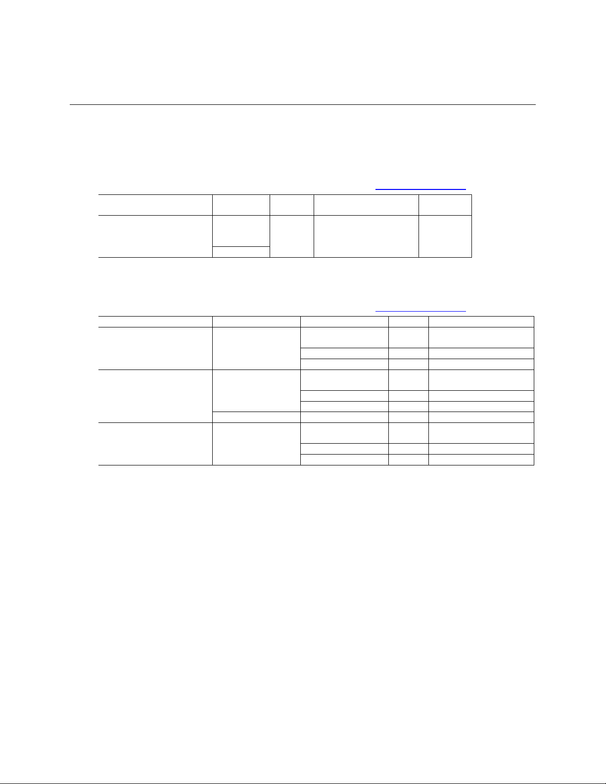
2.1.2 Summary of Kit and Board SKUs
Product Codes and MM#s for the SKUs below can be found at https://ark.intel.com.
Processor
Chassis
AC Cord (C5)
RAM
Storage
Intel® Celeron® N4505
Chassis
US, EU, UK, AU or No
Cord
-
CN - -
No Cord
-
64GB eMMC
Intel® Celeron® N5105
Chassis
US, EU, UK, AU, IN or
No Cord
-
CN - -
No Cord
-
64GB eMMC
Board
No Cord
-
64GB eMMC
Intel® Pentium® N6005
Chassis
US, EU, UK, AU or No
Cord
-
CN - -
No Cord
-
64GB eMMC
1
“WW” refers to worldwide
2
“CN” refers to China
Page 12

Intel NUC Kit/Mini PC NUC11AT{X} Technical Product Specification
14
2.1.3 Feature Summary
Table 1 summarizes the major features of Intel® NUC Products NUC11ATKPE, NUC11ATKC4,
NUC11ATKC2, and NUC11ATBC4.
Table 1. Feature Summary
Form Factor
4.5 inches by 5.25 inches 114mm x 133mm x 35mm for chassis, (including feet)
Processor
(one of 3 models)
A soldered-down 11th generation Intel® Celeron® N4505 processor with up to a maximum
10 W TDP (if thermal margin is available).
• 2.00 GHz base frequency, 2.90 GHz turbo frequency, 2 threads
• 4 MB Intel® Smart Cache
• Intel® UHD Graphics
• Integrated memory controller
• Integrated PCH
A soldered-down 11th generation Intel® Celeron® N5105 processor with up to a maximum
15 W TDP (if thermal margin is available).
• 2.00 GHz base frequency, 2.90 GHz turbo frequency, 4 threads
• 4 MB Intel® Smart Cache
• Intel® UHD Graphics
• Integrated memory controller
• Integrated PCH
A soldered-down 11th generation Intel® Pentium® N6005 processor with up to a maximum
15 W TDP (if thermal margin is available).
• 2.00 GHz base frequency, 3.30 GHz turbo frequency, 4 threads
• 4 MB Intel® Smart Cache
• Intel® UHD Graphics
• Integrated memory controller
• Integrated PCH
Memory†
• Two 260-pin 1.2 V DDR4 SDRAM Small Outline Dual Inline Memory Module (SO-DIMM)
sockets
• Support for DDR4 2933MHz SO-DIMMs
• Support for 8 Gb and 16 Gb memory technology
†
• Support for up to 32 GB of system memory with two SO-DIMMs using 16 Gb memory
technology†
• Support for non-ECC memory
• Support for 1.2 V low voltage JEDEC memory only
Note: 2 Gb and 4 Gb memory technology (SDRAM Density) is not compatible
Graphics
• Integrated graphics support for processors with Intel® Graphics Technology:
• One High Definition Multimedia Interface* (HDMI*) v2.0b back panel connector
Audio
• Intel® High Definition (Intel
®
HD) Audio via the HDMI interface through the processor
• Realtek HD Audio via 3.5 mm stereo microphone and headphone jacks on the front
panel
Storage
One SATA 6.0 Gbps port is reserved for an M.2 storage module supporting M.2 2242 and
M.2 2280 (key type M) modules
Soldered-down 64GB Embedded MultiMediaCard (eMMC) onboard storage module
†
Note: eMMC only available on select SKUs
Peripheral Interfaces
• USB 3.2 (Gen 1) Type A ports:
• Two ports are implemented via the external front panel connectors (blue)
• USB 3.2 (Gen2) Type A ports
• Two ports are implemented via the external back panel connectors (blue)
• USB 2.0 Type A Ports
Page 13

Technical Reference
15
• Two ports are implemented via the external back panel connectors (black)
Expansion Capabilities
• One M.2 connector supporting M.2 2280 or 2242 (key type M) modules
• One M.2 connector supporting M.2 2230 Wi-Fi expandability
BIOS
• Intel® BIOS resident in the Serial Peripheral Interface (SPI) Flash device
• Support for Advanced Configuration and Power Interface (ACPI), Plug and Play, System
Management BIOS (SMBIOS)
Instantly Available PC
Technology
• Suspend to RAM support
• Wake on PCI Express, LAN, front panel, and USB ports
LAN
Gigabit (10/100/1000Mbps) LAN subsystem using the Realtek RTL8111H-CG Gigabit
Ethernet Controller
Hardware Monitor
Subsystem
Hardware monitoring subsystem, based on an embedded controller, including:
• Voltage sense to detect out of range power supply voltages
• Thermal sense to detect out of range thermal values
• One processor fan header
• Fan sense input used to monitor fan activity
• Fan speed control
Wireless
• Intel Wireless-AC 9462, 802.11ac, Dual Band, 2x2 Wi-Fi+BT
• Available on select SKUs via M.2 2230
• Maximum Transfer speed up to 433Mbs
• Supports OFDMA, 1024QAM, Target Wake Time (TWT) and spatial reuse
• Single external shared antenna via back panel
Table 2. Additional Features
HDMI CEC API
Built-in support for HDMI CEC is available on both HDMI ports, which may be enabled in the
BIOS for display power control, as well as via an API supporting other HDMI CEC functions.
More information about the HDMI CEC API specification is available on
https://www.intel.com/content/www/us/en/support/articles/000056864/intel-nuc.html
Delayed AC Start
Short delay after AC power is applied before unit is ready to power on to protect the system
against voltage fluctuations in environments where multiple devices are being powered on
simultaneously
Kensington Security Slot
Available on the right side of the chassis when viewed from the front
Page 14

Intel NUC Kit/Mini PC NUC11AT{X} Technical Product Specification
16
3 Product Layout
3.1 Board Layout
3.1.1 Board Layout (Bottom)
Figure 1 shows the location of the major components on the bottom of Intel® NUC Products
NUC11ATKPE, NUC11ATKC4, NUC11ATKC2, and NUC11ATBC4
Figure 1. Major Board Components (Bottom)
Page 15

Technical Reference
17
Table 3. Components Shown in Figure 1
Item from Figure 2
Description
A
DC Input Jack Power Button
B
USB 3.2 gen 1x1 port (blue)
C
USB 3.2 gen 1x1 port (blue)
D
Front Panel Header
E
Microphone Jack
F
Headset Jack
G
DDR4 SO-DIMM1 socket
H
DDR4 SO-DIMM2 socket
I
Display Port 1.4 Connector
J
RJ-45 Ethernet Jack
K
2x USB 2.0 Ports (Black)
L
2x USB 3.2 gen 2x1 (Blue)
M
HDMI 2.0b Port
N
DC Input Jack
O
BIOS Security Jumper
P
M.2 22x30 (WIFI)
Q
Power Indicator LED
R
BIOS Battery Connector
S
M.2 22x80/42 Connector
Page 16

Intel NUC Kit/Mini PC NUC11AT{X} Technical Product Specification
18
3.1.2 Board Layout (Top)
Figure 2 shows the location of the major components on the top side of Intel® NUC Products
NUC11ATKPE, NUC11ATKC4, NUC11ATKC2, and NUC11ATBC4.
Figure 2. Major Board Components (Top)
Table 4. Components Shown in Figure 2
Item from Figure 2
Description
A
Fan Header
B
Fan and Thermal Solution
C
Fan and Thermal Solution
Page 17

Technical Reference
19
3.1.3 Front Panel
Figure 3. Front Panel Connectors
3.1.4 Back Panel
f
Figure 4. Back Panel Connectors
Page 18

Intel NUC Kit/Mini PC NUC11AT{X} Technical Product Specification
20
3.1.5 Block Diagram
Figure 5. Block Diagram
Page 19

Technical Reference
21
4 Feature Descriptions
4.1 System Memory
Figure 1 illustrates the memory channel and SO-DIMM configuration.
4.1.1 Intel® NUC Mini PC Memory Information
Intel® NUC Mini PC ship with 2 x 4 GB DDR4 2933MHz SODIMMs included. More information
about available Intel® NUC Mini PCs NUC11ATK can be found in Section 2.1.1 Summary of Mini
PC SKUs.
4.2 Graphics Subsystem
Intel® NUC Products NUC11ATKPE, NUC11ATKC4, NUC11ATKC2, and NUC11ATBC4 support
Intel® UHD Graphics
4.2.1 Intel® UHD Graphics for 11th Gen Intel Processors
Intel® UHD Graphics for 11th Gen Intel Processors features the following:
• DirectX* 12 support
• OpenGL* 4.5 support
• Max HDMI resolution 4096x2160 at 60Hz
• Max DP resolution 4096x2160 at 60Hz
• OpenCL* 2.0 support
4.2.2 Integrated Audio
HDMI and DP interfaces can carry audio along with video. The processor supports two HD audio
streams over two digital ports simultaneously. The processor supports the following audio
formats over HDMI and DP:
• AC-3 Dolby* Digital
• Dolby* Digital Plus
• DTS-HD*
• LPCM, 192 kHz/24 bit, 6 channel
• Dolby* TrueHD, DTS-HD Master Audio*
Audio drivers are built into the Graphics driver and are available from Intel’s website.
4.2.3 Real-Time Clock Subsystem
A coin-cell battery (CR2032) powers the real-time clock and CMOS memory. When the computer
is not plugged into a wall socket, the battery has an estimated life of three years. When the
computer is plugged in, the standby current from the power supply extends the life of the battery.
The clock is accurate to 13 minutes/year at 25 ºC with 3.3 VSB applied via the power supply 5 V
STBY rail.
Page 20

Intel NUC Kit/Mini PC NUC11AT{X} Technical Product Specification
22
NOTE
If the battery and AC power fail, date and time values will be reset and the user will be notified
during the POST.
When the voltage drops below a certain level, the BIOS Setup program settings stored in CMOS
RAM (for example, the date and time) might not be accurate. Replace the battery with an
equivalent one. Figure 2 on page 18 shows the location of the battery.
4.3 LAN Subsystem
4.3.1 RJ-45 LAN Connector with Integrated LEDs
Two LEDs are built into the RJ-45 LAN connector (shown in Figure 6).
Item
Description
A
Link LED (Green)
B
Data Rate LED (Green/Yellow)
Figure 6. LAN Connector LED Locations
Table 5 describes the LED states when the board is powered up and the LAN subsystem is
operating.
Table 5. LAN Connector LED States
LED
LED Color
LED State
Condition
Link
Green
Off
LAN link is not established
Solid
LAN link is established
Blinking
LAN activity is occurring
Data Rate
Green/Yellow
Off
10Mb/s data rate is selected
Yellow
100 Mb/s data rate is selected
Green
1000 Mb/s data rate is selected
Page 21

Technical Reference
23
4.4 Hardware Management Subsystem
4.4.1 Fan Monitoring
Fan monitoring can be implemented using third-party software.
4.4.2 System States and Power States
Table 6 describes the ACPI states supported by the processor.
Table 6. Systems States
State
Description
G0/S0/C0
Full On: CPU operating. Individual devices may be shut to save power. The different
CPU operating levels are defined by Cx states.
GO/S0/Cx
Cx State: CPU manages C-states by itself and can be in lower power states.
G1
Suspend-To-RAM (STR): The system context is maintained in system DRAM, but
power is shut to non-critical circuits. Memory is retained and refreshes continue. All
external clocks are shut off; RTC clock and international oscillator clocks are still
toggling.
G1/S4
Suspend-To-Disk (STD): The context of the system is maintained on the disk. All
power is then shut to the system except to the logic required to resume. Externally
appears the same as S5 but may have different wake events.
G2/S5
Soft Off: System context not maintained. All power is shut except for the logic required
to restart. A full boot is required when waking.
G3
Mechanical Off: System context not maintained. All power shut except for the RTC. No
“Wake” events are possible because the system does not have any power. This state
occurs if the user removes the batteries, turns off a mechanical switch, or if the system
power supply is at a level that is insufficient to power the “waking” logic.
4.4.2.1 Wake-up Devices and Events
Table 7 lists the devices or specific events that can wake the computer from specific states.
Table 7. Wake-up Devices and Events
Devices/events that wake up the
system…
…from this sleep
state
Comments
Power switch
S3, S4, S51
RTC alarm
S3, S4, S51
Option for monitor to remain in sleep
state
LAN
S3, S4, S5
1, 3
“S5 WOL after G3” is supported; monitor
to remain in sleep state
WIFI
S3, S41
Bluetooth
S3, S41
USB
S3, S4, S5
1, 2, 3
Wake S4, S5 controlled by BIOS option
(not after G3)
PCIe
S3, S41
Via WAKE; monitor to remain in sleep
state
Page 22

Intel NUC Kit/Mini PC NUC11AT{X} Technical Product Specification
24
Notes:
1. S4 implies operating system support only.
2. Will not wake from Deep S4/S5. USB S4/S5 Power is controlled by BIOS. USB S5 wake is controlled by BIOS. USB S4
wake is controlled by OS driver, not just BIOS option.
3. Windows Fast startup will block wake from LAN and USB from S5.
NOTE
The use of these wake-up events from an ACPI state requires an operating system that provides
full ACPI support. In addition, software, drivers, and peripherals must fully support ACPI wake
events.
5 Technical Reference
5.1 Connectors and Headers
CAUTION
Only the following connectors and headers have overcurrent protection: back panel USB Type A
and Type C, front panel USB, internal USB headers, internal power header, and DC Vin jack.
All other connectors and headers are not overcurrent protected and should connect only to
devices inside the computer’s chassis, such as fans and internal peripherals. Do not use these
connectors or headers to power devices external to the computer’s chassis. A fault in the load
presented by the external devices could cause damage to the computer, the power cable, and the
external devices themselves.
Furthermore, improper connection of USB header single wire connectors may eventually overload
the overcurrent protection and cause damage to the board.
5.1.1 Signal Tables for the Connectors and Headers
Table 8. SDXC Card Reader Connector
Pin
Signal Name
1
CD/DAT3
2
CMD 3 VSS1
4
VDD1
5
CLK 6 VSS2
7
DAT0/RCLK+
8
DAT1/RCLK-
9
DAT2
10*
VSS3
11*
D0+
12*
D0-
Page 23

Technical Reference
25
13*
VSS4
14*
VDD2
15*
D1-
16*
D1+
17*
VSS5
The board has a full-sized Secure Digital (SD) card reader that supports the Secure Digital
eXtended Capacity (SDXC) format, 4.0 specification, UHS-II bus speed.
NOTE
*Pins 10-17 added with UHS-II v4.0 specification. Not present on all SD cards.
Table 9. M.2 2280 Module (Mechanical Key M) Connector
Pin
Signal Name
Pin
Signal Name
74
3.3V (4A total for pins 74, 72, 70, 18, 16, 14, 12, 4, 2 (0.5A per pin))
75
GND
72
3.3V (4A total for pins 74, 72, 70, 18, 16, 14, 12, 4, 2 (0.5A per pin))
73
GND
70
3.3V (4A total for pins 74, 72, 70, 18, 16, 14, 12, 4, 2 (0.5A per pin))
71
GND
68
SUSCLK(32kHz) (O)(0/3.3V)
69
PEDET (NC-PCIe)
66
Connector Key
67
N/C
64
Connector Key
65
Connector Key
62
Connector Key
63
Connector Key
60
Connector Key
61
Connector Key
58
N/C
59
Connector Key
56
N/C
57
GND
54
PEWAKE# (I/O)(0/3.3V) or N/C
55
REFCLKP
52
CLKREQ# (I/O)(0/3.3V) or N/C
53
REFCLKN
50
PERST# (O)(0/3.3V) or N/C
51
GND
48
N/C
49
PETp0
46
N/C
47
PETn0
44
N/C
45
GND
42
N/C
43
PERp0
40
N/C
41
PERn0
38
DEVSLP (O)
39
GND
36
N/C
37
PETp1
34
N/C
35
PETn1
32
N/C
33
GND
30
N/C
31
PERp1
28
N/C
29
PERn1
26
N/C
27
GND
24
N/C
25
PETp2
22
N/C
23
PETn2
20
N/C
21
GND
Page 24

Intel NUC Kit/Mini PC NUC11AT{X} Technical Product Specification
26
18
3.3V (4A total for pins 74, 72, 70, 18, 16, 14, 12, 4, 2 (0.5A per pin))
19
PERp2
16
3.3V (4A total for pins 74, 72, 70, 18, 16, 14, 12, 4, 2 (0.5A per pin))
17
PERn2
14
3.3V (4A total for pins 74, 72, 70, 18, 16, 14, 12, 4, 2 (0.5A per pin))
15
GND
12
3.3V (4A total for pins 74, 72, 70, 18, 16, 14, 12, 4, 2 (0.5A per pin))
13
PETp3
10
DAS/DSS# (I/O)/LED1# (I)(0/3.3V)
11
PETn3
8
N/C 9 GND 6 N/C 7 PERp3
4
3.3V (4A total for pins 74, 72, 70, 18, 16, 14, 12, 4, 2 (0.5A per pin))
5
PERn3
2
3.3V (4A total for pins 74, 72, 70, 18, 16, 14, 12, 4, 2 (0.5A per pin))
3
GND
1
GND
5.1.1.1 Front Panel Header (2.0 mm Pitch)
This section describes the functions of the front panel header. Table 10 lists the signal names of
the front panel header. Front Panel Header (2.0 mm Pitch) is a connection diagram for the front
panel header.
Table 10. Front Panel Header (2.0 mm Pitch)
Pin
Signal Name
Description
Pin
Signal Name
Description
1
HDD_POWER_LED
Pull-up 750Ω to +5V
2
POWER_LED_MAIN
[Out] Front panel LED (main
color) Pull-up 300Ω to +5V
3
HDD_LED#
[Out] HDD activity LED
4
POWER_LED_ALT
[Out] Front panel LED (alt
color)
5
GROUND
Ground
6
POWER_SWITCH#
[In] Power switch
7
RESET_SWITCH#
[In] Reset switch
8
GROUND
Ground
9
+5V_DC (1A) (Vcc)
Power
10
Key
No pin
5.1.1.1.1 Hard Drive Activity LED Header
Pins 1 and 3 can be connected to an LED to provide a visual indicator that data is being read from
or written to a hard drive. Proper LED function requires a SATA hard drive or optical drive
connected to an onboard SATA connector.
5.1.1.1.2 Reset Switch Header
Pins 5 and 7 can be connected to a momentary single pole, single throw (SPST) type switch that is
normally open. When the switch is closed, the board resets and runs the POST.
5.1.1.1.3 Power/Sleep LED Header
Pins 2 and 4 can be connected to a one- or two-color LED. Table 11 and Table 12 show the
possible LED states.
Table 11. States for a One-Color Power LED
LED State
Description
Off
Power off
Page 25

Technical Reference
27
Blinking
Standby
Steady
Normal operation
Table 12. States for a Dual-Color Power LED
LED State
Description
Off
Power off
Blinking (white)
Standby
Steady (white)
Normal operation
NOTE
The LED behavior shown in Table 11 is default – other patterns may be set via BIOS setup.
5.1.1.1.4 Power Switch Header
Pins 6 and 8 can be connected to a front panel momentary-contact power switch. The switch
must pull the SW_ON# pin to ground for at least 50 ms to signal the power supply to switch on or
off (the time requirement is due to internal debounce circuitry on the board). At least two seconds
must pass before the power supply will recognize another on/off signal.
5.1.1.2 BIOS Security Jumper
CAUTION
Do not move a jumper with the power on. Always turn off the power and unplug the power cord
from the computer before changing a jumper setting. Otherwise, the board could be damaged.
Figure 7 shows the location of the BIOS Security Jumper. The 3-pin jumper determines the BIOS
Security Program’s mode.
Page 26

Intel NUC Kit/Mini PC NUC11AT{X} Technical Product Specification
28
Figure 7. Location of the BIOS Security Jumper
Table 13 describes the jumper settings for the three modes: normal, lockdown, and configuration.
Table 13. BIOS Security Jumper Settings
Function/Mode
Jumper Setting
Configuration
Normal
1-2
The BIOS uses current configuration information and passwords for
booting.
Lockdown
2-3
The BIOS uses current configuration information and passwords for
booting, except:
• All POST Hotkeys are suppressed (prompts are not displayed and
keys are not accepted. For example, F2 for Setup, F10 for the Boot
Menu).
• Power Button Menu is not available (see Section 6.3.2 Power Button
Menu).
BIOS updates are not available except for automatic Recovery due to
flash corruption.
Page 27

Technical Reference
29
Configuration
None
BIOS Recovery Update process if a matching *.cap file is found. Recovery
Update can be cancelled by pressing the Esc key.
If the Recovery Update was cancelled or a matching *.bio file was not
found, a Config Menu will be displayed. The Config Menu consists of the
following (followed by the Power Button Menu selections):
[1] Suppress this menu until the BIOS Security Jumper is
replaced.
[2] Clear BIOS User and Supervisor Passwords.
[3] Reset Intel® AMT to default factory settings.
[4] Clear Trusted Platform Module.
Warning: Data encrypted with the TPM will no longer be
accessible if the TPM is cleared.
[F2] Intel® Visual BIOS.
[F4] BIOS Recovery.
See Section 6.3.2 Power Button Menu
5.1.1.3 Fan Header Current Capability
Table 14 lists the current capability of the fan headers.
Table 14. Fan Header Current Capability
Fan Header
Maximum Available Current
Processor fan
1 A
5.1.1.4 Power Supply Connectors
NOTE External power voltage, 19 (±5%) V DC, is dependent on the type of power
supply used. System power requirements will depend on actual system configurations chosen
by the integrator, as well as end user expansion preferences. It is the system integrator’s
responsibility to ensure an appropriate power budget for the system configuration is properly
assessed based on the system-level components chosen.
5.2 Mechanical Considerations
5.2.1 Form Factor
The board is designed to fit into a custom chassis. Figure 8 illustrates the mechanical form factor
for the board. Dimensions are given in inches [millimeters]. The outer dimensions are
104.1 millimeters (front to back) by 121.6 millimeters (side to side).
Page 28

Intel NUC Kit/Mini PC NUC11AT{X} Technical Product Specification
30
Figure 8. Board Dimensions
Page 29

Technical Reference
31
Figure 9 shows the height dimensions of the board. Dimensions are in mm.
Figure 9. Board Height Dimensions
5.3 Thermal Considerations
CAUTION
Failure to ensure appropriate airflow may result in reduced performance of both the processor
and/or voltage regulator or, in some instances, damage to the board.
All responsibility for determining the adequacy of any thermal or system design remains solely
with the system integrator. Intel makes no warranties or representations that merely following the
instructions presented in this document will result in a system with adequate thermal
performance.
CAUTION
Ensure that the ambient temperature does not exceed the board’s maximum operating
temperature. Failure to do so could cause components to exceed their maximum case temperature
and malfunction. For information about the maximum operating temperature, see the
environmental specifications in Section 5.4.
CAUTION
Ensure that proper airflow is maintained in the processor voltage regulator circuit. Failure to do
so may result in shorter than expected product lifetime.
Page 30

Intel NUC Kit/Mini PC NUC11AT{X} Technical Product Specification
32
5.4 Environmental
Table 15 lists the environmental specifications for the board.
CAUTION
If the external ambient temperature exceeds 35 oC, further thermal testing is required to ensure
components do not exceed their maximum operating temperature.
Table 15. Environmental Specifications
Parameter
Specification
Temperature
Sustained Storage Limits (i.e.
warehouse)
-20 C to +40 C
Short Duration Limits (i.e. shipping)
-40 °C to +60 °C
Ambient Operating – NUC Kit*
0 C to +35 C
Ambient Operating – NUC Board*
0 C to +35 C
* Processor performance may automatically decrease when the system
operates in the top 5 °C of the ambient operating temperature ranges above.
Shock (Board)
Unpackaged
50 g trapezoidal waveform
Velocity change of 170 inches/s²
Packaged
Free fall package drop machine set to the height determined by the weight
of the package.
Product
Weight
(pounds)
Non-palletized Product
drop height (inches)
Palletized drop heights (single
product) (inches)
<20
36
N/A 21-40
30
N/A 41-80
24
N/A
81-100
18
12 100-120
12 9
Vibration (System)
Unpackaged
Random profile 5 Hz to 40 Hz @ 0.015 g^2/Hz to 500 Hz @ 0.00015
g^2/Hz(slope down)
Input acceleration is 1.09 gRMS
Packaged
Random profile 5 Hz to 40 Hz @ 0.015 g^2/Hz to 500 Hz @ 0.00015
g^2/Hz(slope down)
Input acceleration is 1.09 gRMS
Note: The operating temperature of the board may be determined by measuring the air temperature from the junction of
the heatsink fins and fan, next to the attachment screw, in a closed chassis, while the system is in operation.
Note: Before attempting to operate this board, the overall temperature of the board must be above the minimum
operating temperature specified. It is recommended that the board temperature be at least room temperature
before attempting to power on the board. The operating and non-operating environment must avoid condensing
humidity.
Page 31

Technical Reference
33
6 Overview of BIOS Features
6.1 Introduction
The board uses an Intel AMI BIOS core that is stored in the Serial Peripheral Interface Flash
Memory (SPI Flash) and can be updated through multiple methods (see Section 6.2). The SPI
Flash contains the BIOS Setup program, POST, the PCI auto-configuration utility, LAN EEPROM
information, and Plug and Play support. The SPI Flash includes a 256 MB flash memory device.
The BIOS Setup program can be used to view and change the identification information and the
BIOS settings for the system. The BIOS Setup program is accessed by pressing <F2> after the
POST memory test beings and before the operating system boots.
6.2 BIOS Updates
The BIOS can be updated using one of the following methods:
1. Express BIOS (Windows-based) Update
2. F7 Update
3. Power Button Menu Update
4. UEFI Shell Update
More information and instructions on how to use each of these methods can be found at BIOS
Update and Recovery Instructions. All BIOS update files for Intel NUCs are available on Download
Center.
6.2.1 BIOS Recovery
It is unlikely that anything will interrupt a BIOS update; however, if an interruption occurs the
BIOS could be unstable. Table 16 lists the drives and media types that can be used for BIOS
recovery. The BIOS recovery media does not need to be made bootable. More information about
BIOS recovery methods and instructions can be found at BIOS Update and Recovery Instructions.
Table 16. Acceptable Drives/Media Type for BIOS Recovery
Media Type
(Note)
Can be used for BIOS recovery?
Hard disk drive (connected to SATA or USB)
Yes
USB flash drive
Yes
NVME SSD (M.2 interface)
Yes
NOTE Supported file systems for BIOS recovery: NTFS (sparse, compressed, or encrypted
files are not supported), FAT32, EXT
6.3 Boot Options
In the BIOS Setup program, the user can choose to boot from a hard drive, removeable driver, or
the network. The default setting is for the hard drive to be the first boot device, the removeable
drive second, and the network third.
Page 32

Intel NUC Kit/Mini PC NUC11AT{X} Technical Product Specification
34
NOTE The network can be selected as a boot device. This selection allows booting from the
onboard LAN or a network add-in card with a remote boot ROM installed. Pressing the <F12> key
during POST automatically forces booting from the LAN. To use this key during POST, the User
Access Level in the BIOS Setup program’s Security menu must be set to Full.
6.3.1 Boot Device Selection During Post
Pressing the <F10> key during POST causes a boot device menu to be displayed. The menu
displays the list of available boot devices.
6.3.2 Power Button Menu
As an alternative to Configuration Mode or normal POST hotkeys, the user can use the power
button to access a menu with BIOS and boot options. The Power Button Menu is accessible via
the following sequence:
1. System is in S4/S5 (not G3)
2. User pushes the power button and holds it down for 3 seconds
3. The Front Panel Power Button LED will be on for the first 3 seconds. After 3 seconds, the LED
will begin to blink in the following pattern: 0.25 seconds off, 0.25 seconds on, 0.25 seconds
off to signal the user to release the power button
4. User releases the power button before the 4-second shutdown override
If this boot path is taken, the BIOS will use default settings, ignoring settings in VPD where
possible. At the point where Setup Entry/Boot would be in the normal boot path, the BIOS
will display the following prompt and wait for a keystroke:
If an unrecognized key is hit, then the BIOS will do nothing and wait for another keystroke. If
one of the listed hotkeys is hit, the BIOS will follow the indicated boot path. Password
requirements must still be honored.
Table 17. Power Button Menu Options
Keystroke
Option
Description
[ESC]
Normal Boot
[F2]
BIOS Setup Menu
[F3]
Disable Fast Boot
Note: Will only be displayed if at least one Fast Boot optimization is
enabled.
If Disable Fast Boot is selected, the BIOS will disable all Fast Boot
optimizations and reset the system.
[F4]
BIOS Recovery
The BIOS will search for a matching .CAP file from the \EFI\Intel folder in
the supported media with the supported file system. If a matching
recovery capsule is found, the BIOS will display the following:
BIOS will Recover to <BIOSID> in 20 seconds.
[ESC] Cancel Recovery
Recovery will proceed if not cancelled via the ESC key within 20 seconds.
The BIOS shall display the recovery progress. If a BIOS .CAP file was not
detected (or the BIOS Recovery was cancelled) then the BIOS will reset
the system and continue normally to POST.
[F5]
Restore BIOS Settings
The BIOS will restore the current setup settings and the current defaults
to the build time defaults in the case of a boot issue caused by setup
variable changes.
Page 33

Technical Reference
35
[F7]
Update BIOS
BIOS Update during the BDS phrase. The BIOS will update independent of
any OS loading and provides a menu UI accessible during boot up. This is
not a recovery tool and will not overwrite a corrupt BIOS or ME firmware.
[F9]
Remote Assistance
Note: Will only be displayed if Remote Assistance is supported.
[F10]
Enter Boot Menu
[F12]
Network Boot
6.4 Hard Disk Drive Password Security Feature
The Hard Disk Drive Password Security feature blocks ready and write access to the hard disk
drive until the correct password is given. Hard disk drive passwords are set in BIOS Setup and are
prompted for BIOS POST. For convenience, when resuming from S3, the BIOS will automatically
unlock all/any drives. Valid password characters are A-Z, a-z, and 0-9. Passwords may be up to 32
characters in length.
The User hard disk drive password, when set, will be required on each power cycle until the
Master Key or User hard disk drive password is submitted.
The Master Key hard disk drive password, when set, will not lock the drive. The Master Key hard
disk drive password exists as an unlock override if the User hard disk drive password is forgotten.
Only the User hard disk drive password, when set, will cause a hard disk to be locked on a system
power cycle. Table 18 show the effects of setting the hard disk drive passwords.
Table 18. Master Key and User Hard Disk Drive Password Functions
Password Set
Password During Boot
Neither
None
Master only
None
User only
User only
Master and User Set
User
During every POST, if a User hard disk drive password is set, POST execution will pause with the
following prompt to force the User to enter the Master Key or the User hard disk drive password:
“Enter Hard Disk Drive Password:”
Upon successful entry of the Master Key or User hard disk drive password, the system will continue
with normal POST.
If the hard disk drive password is not correctly entered, the system will go back to the above
prompt. The User will have three attempts to correctly enter the hard disk drive password. After
the third unsuccessful attempt, the system will halt with the following message:
“Hard Disk Drive Password Entry Error”
A manual power cycle will be required to resume system operation.
NOTE As implemented on the Intel NUC11PAB board, the hard disk drive password security
feature is only supported on the SATA Port 0 (M.2) or the SATA port 1 (onboard SATA connector).
Page 34

Intel NUC Kit/Mini PC NUC11AT{X} Technical Product Specification
36
6.5 BIOS Security Features
The BIOS includes security features that restrict access to the BIOS Setup program and who can
boot the computer. A Supervisor and User password can be set for the BIOS Setup program and
for botting the computer, with the following restrictions:
• The Supervisor password gives unrestricted access to view and change all the Setup
options in the BIOS Setup program. This is Supervisor Mode.
• The User password gives restricted access to view and change Setup options in the BIOS
Setup program. This is User Mode.
• If only the Supervisor password is set, pressing the <Enter> key at the password prompt of
the BIOS Setup program allows the user restricted access to Setup.
• If both the Supervisor and User passwords are set, users can enter either the Supervisor or
User password to access Setup. Users have access to Setup regardless to which password
is used.
• Setting the User password restricts who can boot the computer. The password prompt
will be displayed before the computer boots. If only the Supervisor password is set, the
computer boots without asking for a password. If both passwords are set, the user can
enter either password to boot the computer.
• For enhanced security, use different passwords for the Supervisor and User passwords.
• Valid password characters are A-Z, a-z, 0-9, and special characters. Passwords may be up
to 20 characters in length.
• To clear a set password, enter a blank password after entering the existing password.
Table 19 shows the effects of setting the Supervisor password and User password. This table is
for reference only and is not displayed on the screen.
Table 19. Supervisor and User Password Functions
Password Set
Supervisor Mode
User Mode
Setup Options
Password to
Enter Setup
Password
During Boot
Neither
Any user can
change all options
Any user can change
all options
None
None
None
Supervisor only
Can change all
options
Can change a limited
number of options
Supervisor Password
Supervisor
None
User only
N/A
Can change all
options
Enter Password
Clear User Password
User
User
Supervisor and
User set
Can change all
options
Can change a limited
number of options
Supervisor Password
Enter Password
Supervisor or
User
Supervisor or
User
6.6 BIOS Error Messages
Table 20 lists the error messages and provides a brief description of each.
Table 20. BIOS Error Messages
Error Message
Explanation
CMOS Battery Failure
The battery may be losing power. Replace the battery soon.
CMOS Checksum Error
The CMOS checksum is incorrect. CMOS memory may have been corrupted. Run Setup to
reset values.
Memory Size Decreased
Memory size has decreased since the last boot. If no memory was removed, then the
memory may be bad.
Page 35

Technical Reference
37
CMOS Timer Not Set
The battery may be losing power. Replace the battery soon.
Processor Thermal Trip
Processor overheated.
Auto RTC Reset
The system triggers RTC clear to recover the system back to the normal condition from
consecutive boot failure.
 Loading...