

Page 1

Intel® E7500 and Intel® E7501
Chipsets MCH
Thermal Design Guide for Embedded Applications
March 2003
Order Number: 273819-002
Page 2

INFORMATION IN THIS DOCUMENT IS PROVIDED IN CONNECTION WITH INTEL® PRODUCTS. NO LICENSE, EXPRESS OR IMPLIED, BY
ESTOPPEL OR OTHERWISE, TO ANY INTELLECTUAL PROPERTY RIGHTS IS GRANTED BY THIS DOCUMENT. EXCEPT AS PROVIDED IN
INTEL'S TERMS AND CONDITIONS OF SALE FOR SUCH PRODUCTS, INTEL ASSUMES NO LIABILITY WHATSOEVER, AND INTEL DISCLAIMS
ANY EXPRESS OR IMPLIED WARRANTY, RELATING TO SALE AND/OR USE OF INTEL PRODUCTS INCLUDING LIABILITY OR WARRANTIES
RELATING TO FITNESS FOR A PARTICULAR PURPOSE, MERCHANTABILITY, OR INFRINGEMENT OF ANY PATENT, COPYRIGHT OR OTHER
INTELLECTUAL PROPERTY RIGHT. Intel products are not intended for use in medical, life saving, life sustaining applications.
Intel may make changes to specifications and product descriptions at any time, without notice.
Designers must not rely on the absence or characteristics of any features or instructions marked “reserved” or “undefined.” Intel reserves these for
future definition and shall have no responsibility whatsoever for conflicts or incompatibilities arising from future changes to them.
®
The Intel
published specifications. Current characterized errata are available on request.
Contact your local Intel sales office or your distributor to obtain the latest specifications and before placing your product order.
Copies of documents which have an ordering number and are referenced in this document, or other Intel literature may be obtained by calling
1-800-548-4725 or by visiting Intel's website at http://www.intel.com.
AlertVIEW, AnyPoint, AppChoice, BoardWatch, BunnyPeople, CablePort, Celeron, Chips, CT Connect, CT Media, Dialogic, DM3, EtherExpress,
ETOX, FlashFile, i386, i486, i960, iCOMP, InstantIP, Intel, Intel logo, Intel386, Intel486, Intel740, IntelDX2, IntelDX4, IntelSX2, Intel Create & Share,
Intel GigaBlade, Intel InBusiness, Intel Inside, Intel Inside logo, Intel NetBurst, Intel NetMerge, Intel NetStructure, Intel Play, Intel Play logo, Intel
SingleDriver, Intel SpeedStep, Intel StrataFlash, Intel TeamStation, Intel Xeon, Intel XScale, IPLink, Itanium, LANDesk, LanRover, MCS, MMX, MMX
logo, Optimizer logo, OverDrive, Paragon, PC Dads, PC Parents, PDCharm, Pentium, Pentium II Xeon, Pentium III Xeon, Performance at Your
Command, RemoteExpress, Shiva, SmartDie, Solutions960, Sound Mark, StorageExpress, The Computer Inside., The Journey Inside,
TokenExpress, Trillium, VoiceBrick, Vtune, and Xircom are trademarks or registered trademarks of Intel Corporation or its subsidiaries in the United
States and other countries.
*Other names and brands may be claimed as the property of others.
Copyright © Intel Corporation, 2003
E7500 and Intel® E7501 Chipsets MCH may contain design defects or errors known as errata which may cause the product to deviate from
2 Thermal Design Guide
Page 3

Contents
Contents
1.0 Introduction....................................................................................................................................5
1.1 Document Goals....... .................................................. ..........................................................5
1.2 Document Scope.................................................................................................................. 5
1.3 Design Flow.......................................................................................................................... 5
1.4 Definition of Terms................................................................................................................6
1.5 Reference Documents........................................................................................................ ..6
2.0 Packaging Technology .................................................................................................................7
3.0 Thermal Simulation .......................................................................................................................9
4.0 Thermal Specifications ...............................................................................................................11
4.1 Power..................................................................................................................................11
4.2 Die Temperature.................................................................................................................11
5.0 Therm al Metrology ......................................................................................................................13
5.1 Die Temperature Measurements........................................................................................13
5.1.1 90° Angle Attach Methodology ..............................................................................13
5.1.2 0° Angle Attach Methodol o g y............ ......................................................... ...........14
5.2 Power Simulat ion Software....... ...................................................................................... ....16
6.0 Referen ce Th erm al So lution....................................................................................................... 17
6.1 Operating Environment and Thermal Performance ............................................................17
6.2 Mechanical Design Envelope .............................................................................................18
6.3 Thermal Solution Assembly................................................................................................19
6.3.1 Retention Method A ...............................................................................................20
6.3.1.1 Heat Sink Orientations...........................................................................20
6.3.1.2 B oard Lev el Keep-out Dimens ions ........................................................ 20
6.3.1.3 Heat Sink Clip........................................................................................22
6.3.1.4 Solder-Down Anch o rs........ ....................................................................22
6.3.2 Retention Method B ...............................................................................................22
6.3.2.1 Heat Sink Orientations...........................................................................23
6.3.2.2 B oard Lev el Keep-Ou t Dimensions........................................................23
6.3.2.3 Heat Sink Push-Pin................................................................................24
6.3.3 Mechanical Interface Material................................................................................24
6.3.4 Thermal Interface Material..................................................................................... 24
6.4 Reliability Requirements.....................................................................................................25
7.0 Con clu sion...................................................................................................................................27
A Thermal Solution Component Suppliers...................................................................................29
A.1 Extru d ed Pi n Fin Heat Sink.......................................... ...............................................................29
A.2 Materials for Retention Method A...............................................................................................29
A.3 Materials for Retention Method B...............................................................................................29
A.4 Attach Hardware.........................................................................................................................30
B Mechanical Drawings..................................................................................................................31
Thermal Design Guide 3
Page 4

Contents
Figures
1 Thermal Design Process..............................................................................................................5
2Intel
®
E7500 and Intel® E7501 Chipsets MCH Package Dimensions..........................................7
3 90° Angle Attach Methodology...................................................................................................14
4 0° Ang l e Att a ch Met h odology.....................................................................................................15
5 0° Ang l e Att a ch Heat Si nk Modification s............ ........................................................................15
6 Thermal Solution Deci sion Flowchart.........................................................................................16
7 Theta ja versus Airflow for the Reference Thermal Solution......................................................18
8 Reference Heat Sink Volumetric Envelope for the MCH............................................................ 19
9 Reference Thermal Solution Assembly Using Retention Method A ...........................................20
10 Heat Sink Retention Mechanism Layout for Retention Method A ..............................................21
11 Retention Mechanism Compone nt Keep-out Zones fo r Retention Metho d A.............................21
12 Reference Thermal Solution Assembly Using Retention Method B...........................................22
13 Board Component Keep-o ut for Retention Method B. ................................................................23
14 Heat Sink Mechanical Gasket, Optional Two-Pie ce . ..................................................................24
15 MCH Heat Sink...... .....................................................................................................................32
16 Heat Sink Clip.......... ..................................................................................................... ..............33
17 Push-pin.....................................................................................................................................34
Tables
1 Definition of Terms .......................................................................................................................6
2 Refer e n ce Documents..................................................................................................................6
3Intel
4 Theta ja Required versus Device and Configuration..................................................................17
5 Reliability Requirements.............................................................................................................25
6 Mechanical Drawing List.............................................................................................................31
®
E7500 and Intel® E7501 Chipsets MCH Thermal Speci fications .....................................11
Revision History
Date Revision Description
Revised Table 3, “Intel
March 2003 002
November 2002 001 Initial rele ase of this document.
MCH Thermal Specifications.”
Revised Table 4, “Theta ja Required versus Dev ice and
Configuration.”
4 Thermal Design Guide
®
E7500 and Intel® E7501 Chipsets
Page 5
Intel® E7500 and Intel® E7501 Chipsets MCH Thermal Design Guide
1.0 Introduction
1.1 Document Goals
The objective of thermal management is to ensure that the temperatures of all components in a
system are maint ai ned within f u nction al limit s . The func tional te mper ature li mit i s the ra nge withi n
which the electric al circuits may be expec ted to meet specified performance requirements.
Operation outs ide the functional li mi t ma y degrade system performance , ca us e logic errors, or
cause component and /or s ystem damage. Temperatures exceeding the maximum operating limits
may result in irreversible changes in the operating characteristics of the component. Th e goal of
this document is to provide an understanding of the operating limits of the Intel
E7501 chipset MCHs and describe a re ference thermal solution for embedded applications.
1.2 Document Scope
This document addres ses thermal design and specifications for the Intel E7500 and I ntel E7501
chipset MCH components on ly. For thermal design information on other chipset components, refer
to the respective com ponent thermal design gu ides. For the Intel
®
PCI-64 Hub 2 (P64H2) Thermal Design Guidelines.
Intel
®
E7500 and Intel®
®
P64H2, refer to the
For general thermal enabling of the Intel E7501 chipset, refer to the Intel
and Intel
®
E7505 Chipsets MCH Thermal Design Guidelines.
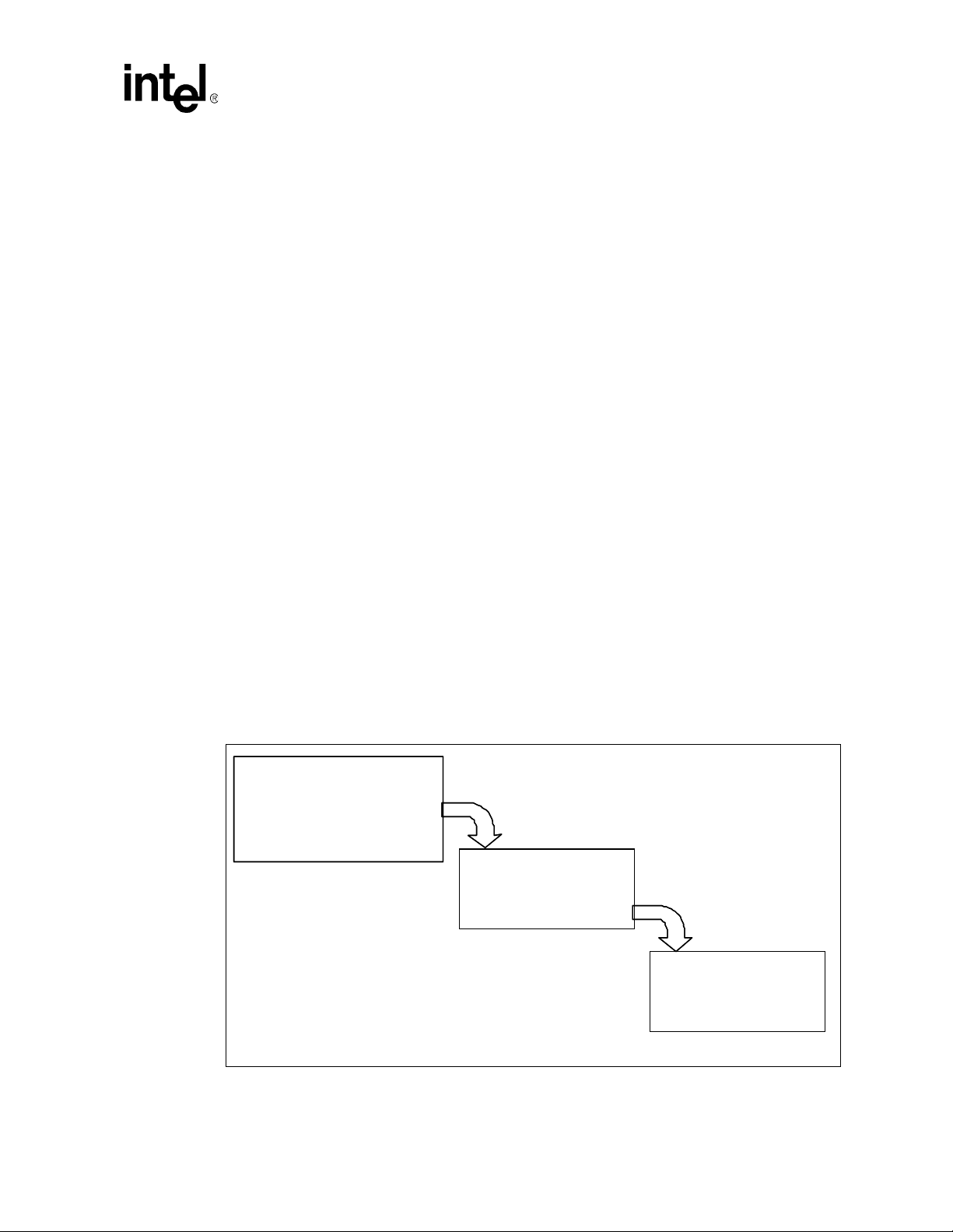
1.3 Desig n Flo w
To develop a reliable, cost-effective thermal solution, several tools have been provided to the
system designer. Figure 1 shows the design process implicit to this document and the tools
appropriate for eac h st ep.
Figure 1. Thermal Design P roc ess
Step 1 : Thermal Simulation
Step 1 : Thermal Simulation
• Therma l model
• Therma l model
• Therma l model user’s gui de
• Therma l model user’s gui de
Step 2: Heat Sink Selection
• Thermal reference
• Thermal reference
•
• Mechanical reference
®
E7500, Intel® E7501,
Step 3: Thermal Validatio n
Step 3: Thermal Validatio n
• Thermal testing software
• Thermal testing software
•
•
Software user’s guide
Thermal Design Guide 5
Page 6

Intel® E7500 and Intel® E7501 Chipsets MCH Thermal Design Guide
1.4 D ef initio n of Terms
Table 1 lists the definitions of terms us ed in this document.
Table 1. Definition of Term s
Term Definition
BGA
ICH3-S
MBGA Mini Ball Grid Array. A version of the BGA wit h a small er ball pitch.
MCH
FC-BGA
P64H2 Bus Controller Hub. The chip set component tha t interfaces the PCI-X buses.
T
case-nhs
T
die-nhs
T
die-hs
TDP
Ball Grid Array. A package type defined by a resin-fiber substrate, onto which a die is
mounted, bo nd ed and encap s ul at ed in mol di ng com po un d. Th e pri ma ry el ectr i cal in ter fac e is
an array of solder balls attached to the substrate opposite the die and molding compound.
I/O Controller Hub. The chipset component that contains the primary PCI interface, LPC
interface, USB , ATA-100, and other legacy functions.
Memory Controller Hub. The chipset component that contains the processor interface and
the memory inte rfa ce .
Flip Ch ip Bal l Gr id A r ray. A packagi ng t echno l ogy us ed fo r th e Int e l
chipset MCHs.
The maximum package case te mperature without any package thermal soluti on. This
temperature is measured at the geometric center of the top of the package case.
The maximum die temperature withou t any package thermal solution. This temperature is
measured at the geometric cente r of the top of the package die.
The maximum die temperatur e with the reference thermal solution attached. This
temperature is measured at the geometric center of the top of the package die.
Thermal Design Power. Thermal solutions should be designed to dissipate this target power
level.
1.5 Reference Documents
Table 2 lists the reference documents an d related document number or source.
®
E7500 and In te l® E7501
Table 2. Reference Documents
Document Document Number
®
Intel
E7500, Intel® E7501, and Intel® E7505 Chipsets MCH Thermal
Design Guidelines
Low Voltage Intel
Thermal Design Guidelines
®
Intel
Xeon™ Processor MP Thermal Design Guidelines 298650
®
PCI-64 Hub 2 (P64H2) Thermal Design Guidelines Contact your local Intel Representative
Intel
®
82801CA I/O Controlle r Hub 3 (ICH3-S) Datasheet 290733
Intel
®
E7500 and Intel® E7501 Chipset Flother m * Model and User’s
Intel
Guide
Thermal Design Su ggestions for Various Fo rm Factors Available at http://www.formfactors.org
®
Intel
E7500 Chipset MCH Thermal Testing Software Contact your local Intel Representative
®
Xeon™ Processor Thermal Design Guidelines 298348
Intel
®
XeonTM Processor for Embedded Applications
Contact your local Intel Representative
298647
273764
6 Thermal Design Guide
Page 7
Intel® E7500 and Intel® E7501 Chipsets MCH Thermal Design Guide
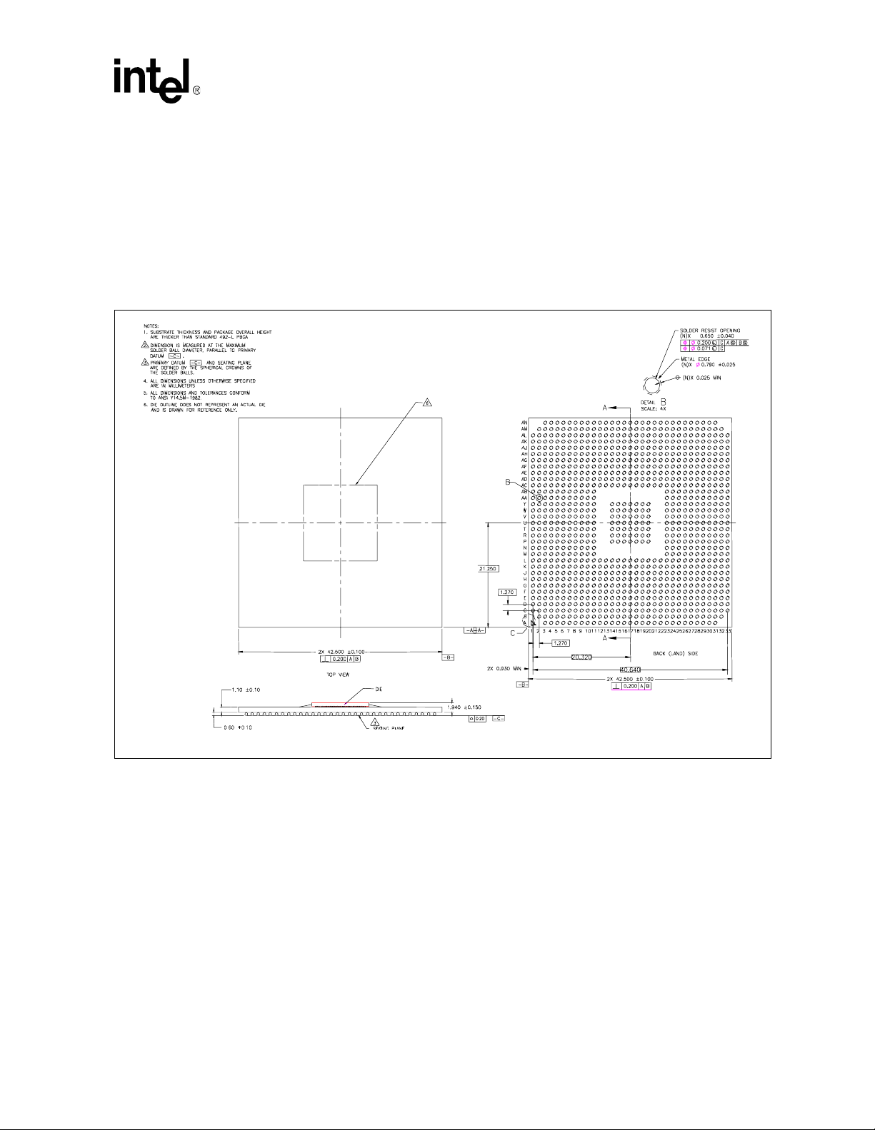
2.0 Packaging Technology
The Intel® E7500 and Intel® E7501 chipsets consist of thre e individual components, the memory
controller hub (MCH), bus controller hub (P64H2), and I/O controller hub (ICH3-S). Th e Inte l
E7500 and E7501 MCHs utilize a 42.5 mm, 6-layer FC-BGA package shown in Figure 2. Refer to
the Intel
component and to the Intel
on the ICH3-S component.
Figure 2. Intel
®
PCI-64 Hub 2 (P64H2) Thermal Design Guidelines for information on the P64H2
®
E7500 and Intel® E7501 Chipsets MCH Package Dimensions
®
82801CA I/O Controller Hub 3 (ICH3-S) Datasheet for information
®
NOTE: Dimensions are in mm.
Thermal Design Guide 7
Page 8

Intel® E7500 and Intel® E7501 Chipsets MCH Thermal Design Guide
This page intentionally left blank.
8 Thermal Design Guide
Page 9

Intel® E7500 and Intel® E7501 Chipsets MCH Thermal Design Guide
3.0 Thermal Simulatio n
Intel provides thermal simulation models of the Intel® E7500 chipset MCH and associated user’s
guides to aid sys tem designers in simulating, analyz ing, and optimizing their thermal so lutions in
an integrated system-level environment. The models are for use with the commercially available
Computation al Fluid Dynamics (CFD)-based thermal analys is tool FLOTHERM* (version 3.1 or
higher) by F lom erics Inc. Contact your Intel Field Sales represe ntative to order the therm al models
and user’s guides. The Intel E7500 chi pset MCH thermal model may also be us ed for simulating
the Intel
E7501 chipset MCH.
Thermal Design Guide 9
Page 10

Intel® E7500 and Intel® E7501 Chipsets MCH Thermal Design Guide
This page intentionally left blank.
10 Thermal Design Guide
Page 11

Intel® E7500 and Intel® E7501 Chipsets MCH Thermal Design Guide
4.0 Thermal Specifications
4.1 Power
See Table 3 for TDP specifications for the Intel® E7500 MCH and the Intel® E7501 chips et MCH.
FC-BGA packages have poor heat transfer capability into the board and have minimal the rma l
capability without thermal solutions. Intel recommends that sys tem designers pl an for one or more
heat sinks when using the Intel E7500 or Intel E7 501 chipset components.
4.2 Die Temper ature
To ensure proper operation and reliability of the Intel E7500 and Intel E7501 chipset MCHs, the
die temperature s must be at or below the values speci f ied in Table 3. Refer to Section 5.0 for
guidelines on accurately measuring package die temperatures.
Table 3. Intel
Intel
Intel
(Paired with Intel
Intel
configuration)
Intel E7501 Chipset MCH
(Paired with Intel Xeon processor or Low Voltage
Intel
configuration)
Intel E7501 Chipset MCH
(Paired with Intel
channel memory configuration)
Intel E7501 Chipset MCH
(Paired with Intel Pentium M processor, single
channel memory configuration)
†T
®
E7500 and Intel® E7501 Chipsets MCH Thermal Specifications
Device
®
E7500 Chipset MCH 102° C 7.5 W
®
E7501 Chipset MCH
Xeon processor, dual channel memory
Xeon processor, single chan ne l me mo r y
die-hs
®
Xeon™ proces sor or Low Voltage
®
Pentium® M proces sor, dual
is defined as the maximum die temperature with the ref erence thermal solution attached.
Parameter (Maximum)
†
T
die-hs
105° C 8.5 W
105° C 7.8 W
105° C 7.1 W
105° C 6.2 W
TDP
Thermal Design Guide 11
Page 12

Intel® E7500 and Intel® E7501 Chipsets MCH Thermal Design Guide
This page intentionally left blank.
12 Thermal Design Guide
Page 13

Intel® E7500 and Intel® E7501 Chipsets MCH Thermal Design Guide
5.0 Thermal Metrology
The system designer must obtain temperature measurements in order to accurately determine the
thermal performance of the system. Intel has established guidelines for proper techniques of
measurin g c h i pset MC H die temperatures . Sec tion 5.1 provides guidelines on how to accurately
measur e th e MCH die temperatures. Section 5.2 contains information on running an application
program that will emulate anticipat ed maximum thermal design powe r. The flowchart in Figure 6
offers useful guidelines for the r mal performance and evaluation.
5.1 Die Temperature Measurements
T o ensure functio nal ity and reli abi lity, the chipset MCH is specifi ed for prope r operati on whe n T
is mainta ined at or below its respectiv e ma ximum temperature listed in Table 3. The surface
temperature at the ge ome tric center of the die corresponds to T
care to en su r e an acc u ra t e tempera tur e m e asu r ement.
Temperature differences between the temperature of a surface and the surrounding local ambient
air may introduc e erro r in the measur ement s. The measure ment err ors may be due to a p oor therm al
contact between the thermocouple junction and the surface of the package, heat loss by radiation
and/or convection, conduc tion through thermocouple leads, or conta ct between the thermocouple
cement and the heat sink base (when a heat sink is used). To minimize these measurement errors,
the following approaches are recommended for thermocouple attach.
5.1.1 90° Angle Attach Methodology
1. Use 36-gauge or smaller diameter K-type thermocouples.
2. Ensure that the thermocouple has be en properly calibrated.
3. Attach the ther mocoupl e b ead or j unctio n to the top su rface of th e di e in th e cent er using a high
thermal conductivity cement. It is critical that the thermocouple bead makes contact with
the die.
4. The thermocouple should be attached at a 90° angle when no interference exi sts between the
thermocouple wire and retention mechanism (see Figure 3). This is the preferred method and
is recommended for use with both bare packages as well as pack ages employing a thermal
solution.
5. The hole size through the heat sink ba se to route the therm ocouple wires out shoul d be smalle r
than 3.3 mm [0.13 in] in diameter.
. Measuring T
die
requires spe cial
die
die
6. Make sure no cont act e xist s bet ween th e therm ocoupl e cem ent a nd heat sink base . This c ont act
will affect the thermocouple reading.
Thermal Design Guide 13
Page 14

Intel® E7500 and Intel® E7501 Chipsets MCH Thermal Design Guide
Figure 3 shows the 90° angle attach methodology.
Figure 3. 90° Angle Attach Methodology
NOTE: Drawing is not to scale.
5.1.2 0° Angle Attach Methodology
1. Mill a 3.3-mm [0.13 in] diameter hole centered on bottom of the heat sink base. The milled
hole should be approximately 1.5 mm [0.06 in] dee p.
2. Mill a 1.3 mm [0.05 i n] wid e slot , 0.5 mm [0.02 in] d eep, fr om the c enter ed hole to one ed ge of
the heat sink. The slot should be in the direction parallel to the heat sink fins (see Figure 5).
3. Attach thermal interface material (TIM) to the bottom of the heat sink base.
4. Cut out portions of the TIM to make room for the thermocouple wire and bead. The cutouts
should match the slot and hole milled into the heat sink bas e.
5. Attach a 36-gauge or smaller calibrated K-type the rmoc ouple bead or junction to the cent er of
the top surface of the die using a high thermal conductivity cement. During this step, make
sure no contact is pres ent between the the r mocouple cement and the hea t s ink base because
any contact will affect the thermocouple reading. It is critical that the thermocouple bead
makes contact with the die (see Figure 4).
6. Attach heat sink assembly to the MCH, and route thermocouple wires out through the milled
slot.
14 Thermal Design Guide
Page 15

Intel® E7500 and Intel® E7501 Chipsets MCH Thermal Design Guide
Figure 4 shows the 0° angle attach methodology.
Figure 4. 0° Angle Attach Met h odology
NOTE: Drawing repres ents the top view and is not to scale.
Figure 5 shows the 0° angle attach heat sink modifications.
Figure 5. 0° Angle Attach Heat Sink Modifications
NOTE: Drawing dimensions are not to scale.
Thermal Design Guide 15
Page 16

Intel® E7500 and Intel® E7501 Chipsets MCH Thermal Design Guide
5.2 Power Simulation Software
The power simulation software is a utility designed to dissipate the thermal design power on an
®
Intel
E7501 chipset MCH when used in conjunction with Intel® Xeon™ processor(s) with 512
Kbytes L2 ca che o r a Low Voltage Intel
the therm al performan ce of the chipset MCH thermal solut ion under “worst-case realistic
application” conditions, Intel has develope d a software utility that operates the chipset at near
worst-case power dis sipation.
The utility has been developed solely for testing customer thermal solutions at near the thermal
design power. Figure 6 shows a decision flowchart for det erm ining thermal solution needs. Real
future applications may exceed the thermal design power limit for transient time periods. For
power supply current re quirements under these transient conditions, please refer to each
component’s EDS or EDS Addendum for the I
Contact your Intel Field Sales representative to obtain a copy of thi s software.
Figure 6. Thermal Solution Decision Flowchart
Start
®
Xeon™ processor with 512 Kbytes L2 cache. To assess
(Max Power Supply Current) specification.
CC
Attach device
to board using
normal reflow
process.
Attach thermocouples using
recommended metrology.
Setup the system in the
desired configuration.
Run the Power
program and
monitor the device
die temperature.
Heatsink requiredSelect Heatsink
Tdie >
Specification?
Yes
No
End
16 Thermal Design Guide
Page 17

Intel® E7500 and Intel® E7501 Chipsets MCH Thermal Design Guide
6.0 Reference Thermal Solution
Intel has developed a reference thermal solution designed to meet the cooling needs of the In tel®
E7500 and Intel
®
E7501 chipset MCHs at worst- ca se embedded condi tions. This section describes
the overall requirements for the refe rence thermal solution, including critical-to-function
dimensions, operating environment, and validation criteria. Other chipset components may or may
not need attached thermal solutions, depending on your specific system local-ambient operating
conditions. Refer to the Intel
®
PCI-64 Hub 2 (P64H2) Thermal Design Guidelines and Intel® I/O
Controller Hub 4 (ICH4) Thermal Design Guidelines for information on therm al solution
requirements and reference thermal solutions.
6.1 Operating Environment and Thermal Performance
The reference thermal solution was designe d assuming a maximum local-ambient temperature of
55° C with a minimum airflow velocity directly upstream of the heatsink of 50 L FM. Assuming
these boundary conditions are met, the refe rence thermal solution will meet the thermal
specifications for the Intel E7500 and Intel E7501 chips et MCHs in all memory and Hub Interface
configurations. See Figure 7 for a plot of the theta ja versus airflow for the reference heatsink
design, and Table 4 for the required theta ja heatsink performances for the Intel E7500 and Intel
E7501 chipset MCHs.
The reference thermal solution provides enough thermal capability to meet the required theta ja for
all of the configurations listed in Table 4 with 50 LFM airflow.
Table 4. Theta ja Required versus Device and Configuration
Device Theta ja Max (° C/W) at TLA = 55° C
®
Intel
E7500 Chipset MCH 6.27° C/W
®
E7501 Chipset MCH
Intel
(Paired with Intel
processor, dual channel memory configuration)
Intel E7501 Chipset MCH
(Paired with Intel Xeon processor or Low Voltage Intel
processor, single channel memory configuration)
Intel E7501 Chipset MCH
(Paired with Intel
configuration)
Intel E7501 Chipset MCH
(Paired with Intel Pentium M processor, single channel memory
configuration)
is defined as the local (internal) ambient temperature directly upstream of the chipset.
†T
LA
®
Xeon™ proces sor or Low Voltage Int el Xeon
Xeon
®
Pentium® M proces sor, dual channel memory
5.88° C/W
6.41° C/W
7.04° C/W
8.06° C/W
Thermal Design Guide 17
Page 18

Intel® E7500 and Intel® E7501 Chipsets MCH Thermal Design Guide
E7500 and E7501 MCH Refer ence Thermal Solut ion
Figure 7 shows the theta ja versus airflow for the referen ce ther mal solution.
Figure 7. Theta ja versus Airfl ow for t he Reference Th erm al So lu t io n
Theta ja vs. Airflow
7.00
6.00
5.00
4.00
3.00
5.8
Theta ja (C/W)
2.00
1.00
0.00
50 100 200
Airflow (LFM)
6.2 Mechanical Design Envelope
Though each design may have unique mechanical volume and height restrictions or
implementa tion requirements, the height, width, and depth constraints typicall y placed on the Intel
E7500 chipset and Intel E7501 chipset MCHs in em bedded environments are shown in Figure 8.
These constraints assume the use of the CompactPCI
4.4
*
blade form factor.
3.4
When using heat sinks that extend beyond the MCH refer ence heat sink envelope shown in
Figure 8, any motherboard components placed betwe en the underside of the heat sink and
motherboard cannot exceed 2.286 mm [0.090 in] in height.
18 Thermal Design Guide
Page 19

Intel® E7500 and Intel® E7501 Chipsets MCH Thermal Design Guide
Figure 8 shows the reference heat sink volumetric e nvelope for the MCH.
Figure 8. Reference Heat Sink Volumetric Envelope for the MCH
NOTE: Drawing dimensions are not to scale.
6.3 Thermal Solution Assembly
The reference thermal solution is a passive extruded heat sink with thermal and mechanical
interfaces. Ther e ar e tw o met h od s f o r at ta ch i n g th e he at sin k to th e motherbo ar d . Th e f irst method
(Retention Met hod A) uses a clip with each end hooked through an anchor soldered to the board.
The second method (Retention Method B) employs the use of four push-pins through the board
using the four holes provided on the heat sink. This method might face layout constraints as the
four holes through the motherboard must be accounted for during board layout. Full mechanical
drawings of the the rma l solution assem bly and the heat sink clip may be found in Appendix B,
“Mechani cal Drawings. ”
Appendix A, “Thermal Solut ion Com ponent Suppliers” lists the Bill-of-Materials and ve ndor
information for each thermal solution component.
Thermal Design Guide 19
Page 20

Intel® E7500 and Intel® E7501 Chipsets MCH Thermal Design Guide
6.3.1 Retention Method A
Retention Method A employs the use of a clip and two solde r-down through board anchors for
mechanical retention. This method is preferred when layout constraints hamper the use of
Retention Me thod B.
Figure 9 shows the reference thermal solution assembly using Retention Method A.
Figure 9. Reference Thermal Soluti on Assembly Us in g Re te n tion Method A
Clip
Heat Sink
Thermal Interface
Mechanical In t er face
Solder-Down Anch or
FC-BGA Package
6.3.1.1 Heat Sink Orientations
When using Ret entio n Met hod A, the heat si nk mus t be al ign ed as sho wn in Figure 9. The heat sink
holes on the same side of the heat sink must be parallel with the clip that applies pressure thro ugh
the center of the hea t s ink.
The airflow m ay approach the heat sink from either perpendicular direct ion. Aligning the heat sink
45° relative to the airflow is acceptable but delivers reduced thermal performance.
6.3.1.2 Board Level Keep-out Dimensio ns
The locations of hole patterns and keep-out zones for the reference thermal solution are shown in
Figure 10 and Figure 11.
20 Thermal Design Guide
Page 21

Intel® E7500 and Intel® E7501 Chipsets MCH Thermal Design Guide
56.34 [2.218]
MCH PIN1
.100" MAX COMPONENT
.070" COMPO NENT
Figure 10 shows the heat sink retention mec hanism layout for Retent ion Method A.
Figure 10. H eat Sink Retent i on Mechanism La yout for Retention Meth od A
60.91 [2.398]
2X 30.45 [1.199]
2X 28.17
[1.109]
NOTE: Drawing dimensions are in milli m eters [in] and are not to scale.
Figure 11 shows the retention mechanism componen t keep-out zones for Retention Method A.
Figure 11. Retention Mechanism Component Keep-out Zones for Retention Method A
.165
.083
2X
.038
PLATED THROUGH HOLE
.173
DETAIL
(.165)
A
KEEPOUT
2X .060
(.345)
.225
.100
SEE DETAIL A
.200
.100
.896
.120
1.156
COMPONENT
KEEPOUT
TRACE KEEPOUT
HEIGHT KEEPOUT
345
.
(.345)
2X
.056
NOTE: Drawing dimensions are in inches and are not to scale.
.170
Thermal Design Guide 21
Page 22

Intel® E7500 and Intel® E7501 Chipsets MCH Thermal Design Guide
6.3.1.3 Heat Sink Clip
Retention Method A employs the use of a wire clip with hooke d ends. The hook s attach to anchors
to fasten the clip to the board. See Figure 16 in Appendix B, “Mechanical Drawings” for a
mechanical drawing of the clip.
6.3.1.4 Solder-Down Anchors
For platforms that have very limited board spa ce , a cl ip retention solde r-down anchor has been
developed t o minimize the im pact of clip ret ention on the board. It is based on a stan dard three-pin
jumper and is soldered to t he board like any common through-hol e header. A new anchor design is
available with 45° bent le ads to increase the anchor attach reliability over time. See Appendix A,
“Thermal Solution Component Suppliers” for the part number and supplier infor mation.
6.3.2 Retention Method B
Retention Method B employ s the use of four push-pins mounted through the four holes on the heat
sink and the mother board. This method requires advance layout noti fication for the four through
holes on the motherboard.
Figure 12 shows the reference thermal solution assembly using Retention Method B.
Figure 12. Reference Thermal Solution Assembly Using Retention Method B
Heat Sink
Push-pin
Thermal Interface Material
Mechanical Interface
FC-BGA Package
22 Thermal Design Guide
Page 23

Intel® E7500 and Intel® E7501 Chipsets MCH Thermal Design Guide
6.3.2.1 Heat Sink Orientations
Retention Met hod B supports an omni-direc tional placement for the heat sink. Airflow may pass
either perpen dicular direction over the fins and the heat sink may be mounted in either the vert ical
or horizontal pos ition atop the MCH, depending on hole placement.
Aligning the heat sink 45° relative to the airflow is acceptable but delivers reduced thermal
performance.
6.3.2.2 Board Level Keep-Out Dimensions
Figure 13 shows the board component keep-out for Retention Method B.
Figure 13. Boar d C om ponent Keep-o ut for Retention Method B
Intel® E7500 Chipset MCH
Intel® E7501 Chipset MCH
NOTE: Draw i ng dim en si ons are in inches and are not to sc al e.
Thermal Design Guide 23
Page 24

Intel® E7500 and Intel® E7501 Chipsets MCH Thermal Design Guide
6.3.2.3 Heat Sink Push-Pin
Four push-pins are required to imple me nt Retention Method B. Vendor information and a detailed
mechanical drawing are located in Appendix B. Currently, the push-pin is available for 0.096 inch
thick motherboards. Other size motherboards might require custom parts from the vendor.
6.3.3 Mechanical Interface Material
Intel recommends the use of a mechanical interface material to avoid cracking of the exposed die
under loading. The interface material reduces mechanical loads experienced by the die. The
reference thermal solution uses a pictu r e fra me gasket of 0.813 mm [0.032 in] thick Poron* foa m.
The foam gasket is a two-piece design, with diagonal cuts at two corners, as shown in Figure 14.
A one-piece gasket design may be used instead without any impact to mechanical performance.
Figure 14. Heat Sink Mechanical Gasket, Optional Two-Piece
NOTE: Drawing dimensions are in millimeters [in] and are not to scale.
6.3.4 Thermal Interface Material
A thermal interface material provides improved conductivity between the die and heat sink. The
reference thermal sol ution is delivered with Powerstrate 51* (manufactured by Po wer Devi ce s,
Inc.) p h ase change material attached.
24 Thermal Design Guide
Page 25

Intel® E7500 and Intel® E7501 Chipsets MCH Thermal Design Guide
6.4 Reliability Requirements
Each motherboard, heat sink, and attach combination may vary the mechanical loading of the
component. The user should carefully evaluate the reliability of the completed assembly prior to
use in high volume. Some general recommendations are pre sented in Table 5.
Table 5. Reliability Requirements
1
Test
Requirement Pass/Fail Criteria
2
Mechan ical Shock 50 g, boar d level, 11 msec, 3 shocks/axis
Random Vibration 7.3 g, board level, 45 min/axis, 50 Hz to 2000 Hz
Temperature Life
Thermal Cycli ng -5° C to +70° C, 500 cycles Visual Check
Humidity 85% relative humidity, 55° C, 1000 hours Visual Check
NOTES:
1. The above tests should be performed on a sample size of at least 12 assemblies from three lots of
material.
2. Additional Pass/Fail Criteria may be added at the discretion of the user.
85° C, 2000 hours total, checkpoints at 16 8, 500,
1000, an d 20 00 hours
Visual Check and Electrical
Functional Test
Visual Check and Electrical
Functional Test
Visual Check
Thermal Design Guide 25
Page 26

Intel® E7500 and Intel® E7501 Chipsets MCH Thermal Design Guide
This page intentionally left blank.
26 Thermal Design Guide
Page 27

Intel® E7500 and Intel® E7501 Chipsets MCH Thermal Design Guide
7.0 Conclusion
As the complexity of computer systems increases, so do the power dissipation requirements. Care
must be taken to ensure that the additional power is properly dissipated. Heat may be dissipated
using improved system cooling, selective use of ducting, and/or passive heat sinks.
The simplest and most cost effective method is to improve the inhere nt system cooling
characteristics through careful design and placement of fans, vents, and ducts. When additional
cooling is req uired, component the rmal solutions may be im plemented in conjunction with system
thermal solutions. The size of the fan or heat s ink may be varied to balance si ze and space
constraints with acoustic noise.
This document has presen ted the c onditio ns and req uireme nts to properly de sign a co oling s olut ion
for systems implementing Intel
Properly desi gned solut ions pro vide ad equate co oling to maint ai n the ch ipse t die te mpera tur es at or
below thermal specifications. This is accompli shed by providing a low local-ambient temperature,
ensuring adequate local airflow, and minimizing the die to local-ambient thermal resistance. By
maintaining the chipset MCH die temper ature at or below those recommende d in this document, a
system designer m ay ensure the proper functionality, performance, and reliability of these chipsets.
®
E7500 or Intel® E7501 chipsets in a n emb edded application.
Thermal Design Guide 27
Page 28

Intel® E7500 and Intel® E7501 Chipsets MCH Thermal Design Guide
This page intentionally left blank.
28 Thermal Design Guide
Page 29

Intel® E7500 and Intel® E7501 Chipsets MCH Thermal Design Guide
Appendix A Thermal So lution Compone nt Suppliers
A.1 Extruded Pin Fin Heat Sink
Part Supplier (Part Number) Contact Information
Pin Fin Heat Sink
(Includes heat sink and attac hed
thermal interface material)
Cooler Master (ECB-00028-01)
A.2 Materials for Retention Method A
Part
Heatsink Clip 1 A69230-001
Board Mount Solder-Down Anchors
(Two anchors required per heat sink.)
Qty Required
(per assy )
2 A13494-005 Foxconn
A.3 Materials for Retention Method B
Intel Part
Number
Wendy Lin
886-2- 34 3 4- 0 05 0, x3 33
wendy@coolermaster.com.tw
Supplier Contact Information
Harry Lin
CCI/ACK
Foxconn
714-739-5797
hlinack@aol.com
Bob Hall
503-693-3509 x235
bhall@foxconn.com
Julia Jiang
(408) 919-6178
juliaj@foxconn.com
Part Supplier (Part Number) Contact Information
Steve Blan k
Push-Pin Peninsula Components (PL 1674)
NOTE: Four pu sh-pins ar e requir ed per heat sink.
(562) 694-4477
steve@pencomsf.com
Thermal Design Guide 29
Page 30

Intel® E7500 and Intel® E7501 Chipsets MCH Thermal Design Guide
A.4 Attach Hardware
Part Intel Part Numbe r Supp lie r Contact Information
Therm al Interfac e
(Powerstrate 51*)
Mechanical Interface
(Poron*)
-- Power Devices, Inc.
A69141-001 Boyd
Mike McPherson
916-686-1432
Mike.McPherson@loctite.com
Rhoda Kennedy
503-972-3170
rkennedy@boydcorp.com
Note: The enabled components may not be currently available from all suppliers. Contact the supplier
directly to ve rify time of component avai lability.
30 Thermal Design Guide
Page 31

Intel® E7500 and Intel® E7501 Chipsets MCH Thermal Design Guide
Appendix B Mechanical Drawings
Table 6 lists the mechanical drawings included in thi s section.
Table 6. Mechanical Drawing List
Drawing Desc r iption Page Number
MCH Heat Sink 32
Heat Sink Clip (for Retentio n Method A) 33
Push-pin (for Retention Method B) 34
Thermal Design Guide 31
Page 32

Intel® E7500 and Intel® E7501 Chipsets MCH Thermal Design Guide
Figure 15. MCH Heat Sink
Used by permission.
32 Thermal Design Guide
Page 33

Figure 16. Heat Sink Clip
Intel® E7500 and Intel® E7501 Chipsets MCH Thermal Design Guide
Thermal Design Guide 33
Page 34

Intel® E7500 and Intel® E7501 Chipsets MCH Thermal Design Guide
Figure 17. Push-pin
Used by permission.
34 Thermal Design Guide
 Loading...