

Page 1

ADE-9040
Intel® Core™ 2 Duo Desktop
Q965 ATX Mother Board
User’s Manual
Rev. 1.0
2007/03/27
P/N: 600C002904010
Page 2

ADE-9040 User’s Manual
Copyright
All rights reserved. The information contained in this guide has been validated and
reviewed for accuracy. No patent liability is assumed with respect to the use of the
information contained herein. While every precaution has been taken in the preparation of
this guide, the Manufacturer assumes no responsibility for errors or omissions.
No part of this publication may be reproduced, stored in a retrieval system, or transmitted in
any form or by any means, electronic, mechanical, photocopying, recording, or otherwise,
without the prior written permission of Manufacturer.
Trademark
Intel®, Pentium® and Celeron® are registered trademarks of Intel® Corporation.
Microsoft® and Windows® are registered trademarks of Microsoft Corporation.
All products and company names are trademarks or registered trademarks of their
respective holders.
These specifications are subject to change without notice.
Technical Support
We hope you to get the maximum performance from your products and be willing to help if
running into technical difficulties. For the most frequently asked questions, it’s easily found
answers from the product documentation and usually a lot more detailed, so please take
reference to this manual first. If the answer still can not be found, gather all the information
or questions applying to the problem, and with the product on hand, contact your distributor,
sales representative, or customer service center for technical support. Most problems
reported are minor and able to be easily solved over the phone. In addition, free technical
support is available and always ready to give advices on application requirements or
specific information on the installation and operation of any of our products.
Please have the following information ready before you call:
1. Product name and serial number
2. Description of your peripheral attachments
3. Description of your software (operating system, version, application software, etc.)
4. A complete description of the problem
5. The exact wording of any error messages
2 / 55
Page 3

ADE-9040 User’s Manual
How to Use This Manual
This manual is written for the system integrator, PC technician and knowledgeable PC end
user. It describes how to configure your ADE-9040 to meet various operating requirements.
The user’s manual is divided into four chapters, with each chapter addressing a basic
concept and operation of the server board.
Chapter 1: Introduction - presents what you have inside the box and gives you an
overview of the product specifications and basic system architecture for the ADE-9040
server board.
Chapter 2: Hardware Configuration Setting - shows the definitions and locations of
Jumpers and Connectors so that you can easily configure your system.
Chapter 3: System Installation - describes how to properly mount the CPU, main memory,
and M-System Flash disk for a safe installation. It will also introduce and show you the
driver installation procedure for the Graphics Controller and Ethernet Controller.
Chapter 4: BIOS Setup Information - specifies the meaning of each setup parameter, how
to get advanced BIOS performance and update to a new BIOS.
3 / 55
Page 4

ADE-9040 User’s Manual
Table of Content
1. Introduction.................................................................................................................8
1.1 Description...........................................................................................................8
1.2 Packing Check List..............................................................................................9
1.3 Specifications....................................................................................................10
1.4 System Architecture..........................................................................................12
1.5 Dimensions........................................................................................................13
2. Hardware Configuration Setting..............................................................................15
2.1 Board Layout .....................................................................................................15
2.2 Jumpers & Connectors.....................................................................................16
2.3 Jumpers/Connectors Setting............................................................................17
2.3.1 RTC Clear CMOS (JP1)...............................................................................17
2.3.2 BIOS Write Protect (JP2)..............................................................................17
2.3.3 AT/ATX Power Select (JP3)..........................................................................17
2.3.4 DVI Select (JP4)...........................................................................................17
2.3.5 P-ATA Select (JP5).......................................................................................17
2.3.6 COM2 RS-232/422/485 Select (JPB1).........................................................17
2.3.7 USB 2/3/4/5/0/1 & LAN1/2 Connectors (CN1, CN2, CN22)..........................17
2.3.8 Internal USB 6/7/8/9 Connectors (CN23, CN24)..........................................17
2.3.9 CPU/System/Chassis Fan Connector (CN4, CN5, CN6)..............................17
2.3.10 CD-In from CD-ROM (CN13)........................................................................17
2.3.11 Extend Line-out Connector (CN14)..............................................................17
2.3.12 Audio Connector (CN15) ..............................................................................18
2.3.13 PS/2 Keyboard & Mouse Connector (CN17) ................................................18
2.3.14 Extend Keyboard & Mouse Connector (CN18).............................................18
2.3.15 Digital I/O Connector (CN19)........................................................................18
2.3.16 VGA & Serial Port 1 Connector (CN20)........................................................18
2.3.17 Serial Port 4 Connector (CN21)....................................................................18
2.3.18 Serial Port 3 & 2 Connectors (CN29, CN30) ................................................18
2.3.19 4-pin ATX Power Connector (CN25)............................................................. 19
2.3.20 24-pin AT X Power Co nnector (CN26)...........................................................19
2.3.21 Front Panel Connector (CN27).....................................................................19
2.3.22 DVI Connector (CN31) .................................................................................20
2.3.23 Serial ATA 1/2/3/4 Connectors (SATA1, SATA2, SATA 3, SATA4) .................20
4 / 55
Page 5

ADE-9040 User’s Manual
3. System Installation...................................................................................................22
3.1 Intel® µFC-LGA775 Processor...........................................................................22
3.1.1 Installing Intel® Core™ 2 Duo / Pentium® 4 / Celeron® D CPU......................22
3.1.2 Installing Intel µFC-LGA 775 CPU Fan, and Heat Sink ................................23
3.1.3 Removing CPU.............................................................................................23
3.2 Main Memory......................................................................................................24
3.3 Installing the ATX Mother Board ......................................................................25
3.4.1 Dual Marvell Gigabit Ethernet Controllers....................................................25
3.4.2 Drivers Support ............................................................................................25
4. BIOS Setup................................................................................................................27
4.1 Entering Setup...................................................................................................27
4.1.1 Main Menu....................................................................................................27
4.1.2 Advanced Setting.........................................................................................28
4.1.3 Advanced PCI/PnP Setting...........................................................................43
4.1.4 Boot Settings................................................................................................46
4.1.5 Security Settings ..........................................................................................49
4.1.6 Advanced Chipset Settings ..........................................................................50
4.1.7 Exit Options..................................................................................................55
5 / 55
Page 6

Revision History
Revision Date Comment
Rev.1.0 Mar. 2007 Initial released
ADE-9040 User’s Manual
6 / 55
Page 7

ADE-9040 User’s Manual
CHAPTER 1
7 / 55
Page 8

ADE-9040 User’s Manual
1. Introduction
1.1 Description
Taking advantages of Intel energy-efficient dual-core processing, ADE-9040 ATX Mother
Board adopts Intel® CoreTM 2 Duo Desktop processors up to 1066 MHz FSB and Intel
Q965 Express chipset with Intel® ICH8R RAID function to fit the high performance computer
system applications for meeting today’s demanding pace and keep complete compatibility
with hardware and software designed. The onboard devices support one PCI Express x16
for an alternative graphics add-in card, one PCI Express x1, four PCI slots, integrated
graphics, and built dual Marvell 88E8053 Gigabit Ethernet controllers offering stable
high-speed networking.
ADE-9040 comes with the Intel® GMA 3000 graphics supporting DVMT 4.0 display memory
up to 256 MB for dual display function by VGA/DVI. The board also features two DIMMs up
to 4 GB SDRAM with dual channel DDR2 533/667/800, enhanced onboard one SATA to
®
Parallel ATA IDE interface supporting Ultra ATA 33/66/100 synchronous mode feature, four
Serial ATA high-speed data transferring at up to 3 GB/s, and 7.1 + 2 CH HDAC through
Realtek ALC883 audio codec. The onboard ITE IT8712F Super I/O chipset supports four
serial ports: one RS-232 serial port interfaces, two RS-232 and one RS-232/422/485 pin
headers, Hardware Monitor function, ten Hi-speed USB 2.0 ports, two 6-pin Mini-DIN
connectors for PS/2 mouse and keyboard, and one 24-pin standard connector designed to
support ATX power function. Besides, a feature of CPU overheat protection will provide
user more security and stability.
Built with these impressed functions, ADE-9040 ATX Mother Board are those ideal
solutions for DVR, KIOSK, medical equipment, industrial automation, financial automation,
process control, semiconductor equipment, and network security markets.
8 / 55
Page 9

ADE-9040 User’s Manual
1.2 Packing Check List
The ADE-9040 package includes the following basic items accompany with this manual.
¾ One ADE-9040 A TX Mother Board
¾ One Quick Installation Guide for ADE-9040
¾ One 40-pin IDE cable
¾ Two Serial ATA cable
¾ One Serial port cable for COM2 or COM3
¾ One Serial port cable for COM4
¾ One USB 2.0 cable
¾ One I/O shield
¾ One Supporting CD-ROM contains User’s Manual and internal VGA display driver
and Marvell Gigabit Ethernet network controller driver and on board devices
drivers
If any of these items is damaged or missed, please contact your vendor and save all
packing materials for future replacement and maintenance.
9 / 55
Page 10

1.3 Specifications
System
ADE-9040 User’s Manual
Intel® Core™ 2 Duo Desktop / Pentium® D / Pentium® 4 / Celeron® D
CPU
FSB 1066/800/533 MHz
BIOS AMI BIOS with 8 Mb Flash EEPROM
System Chipset Intel® Q965 + ICH8R
I/O Chip ITE IT8718F I/O controller
System Memory
Storage
RAID ICH8R supports RAID 0, 1, 5, 10 function
Watchdog Timer Reset: 1 sec.~255 min. and 1 sec. or 1 min./step
H/W Status Monitor
processor in the LGA775 package
(E6000, 900, 800, 600, 500, 300 sequences)
2 x 240-pin DIMM sockets support dual channel DDR2 533/667/800
SDRAM
Max. up to 4 GB memory
1 x SATA to Parallel ATA IDE port with UDMA 33, ATA-66/100 support
4 x Series ATA 300 ports
Monitoring system temperature, voltage, and cooling fan status.
Auto throttling control when CPU overheats.
System automatically restored on recovery of AC power loss.
GPIO On-board programmable 8-bit Digital I/O interface
Expansion 1 x PCI Express x16, 1 x PCI Express x1 and 4 x PCI slots
MIO
Internal I/O 1 x IrDA, 2 x RS-232, 1 x RS-232/422/485, 4 x USB 2.0
Back Panel I/O
Display
Chipset Intel® Q965 Integrated GMA 3000 graphics
Display Memory Intel® DVMT 4.0 supports up to 256 MB video memory
Resolution
VGA/LCD Interface DSUB-15 connector for VGA output
DVI Chrontel CH7307 DVI transmitter
1 x VGA, 1 x Audio jack, 2 x RJ-45, 1 x RS-232, 6 x USB 2.0, 1 x KB,
1 x Mouse
Analog display : up to 2048 x 1536 @ 75Hz (QXGA)
Digital LVDS : up to 2048 x 1536 @ 60 Hz
10 / 55
Page 11

ADE-9040 User’s Manual
Audio
HDAC Realteck ALC883 7.1 + 2CH audio codec
Audio Interface Mic in, Line in, CD Audio in, Line out, Rear out and Center/Subwoofer out
Ethernet
Chipset Dual Marvell® 88E8053 PCI Express™ Gigabit Ethernet controllers
Ethernet Interface IEEE 802.3 10BASE-T/100BASE-TX/1000BASE-T
Mechanical & Environmental
Power Requirement
Power Type 24-pin ATX power connector, 1 x 4-pin ATX 12V power connector
FAN Connector 1 x CPU, 2 x system with DC 12V
Operating Temperature 0~60°C (32~140°F)
Operating Humidity 0%~90% relative humidity, non-condensing
Size (L x W) 12” x 8.7” (305 mm x 220 mm)
Weight 1.44 lbs (650 g)
+3.3 V @ 4.73 A, +5 V @ 0.96 A, +12 V @ 9.11 A, -12 V @ 0.01 A,,
5 VSB @ 0.07A
11 / 55
Page 12
ADE-9040 User’s Manual
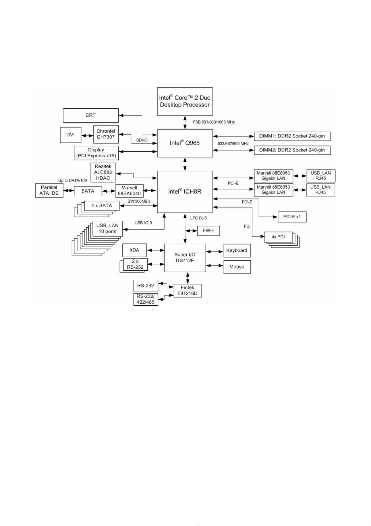
1.4 System Architecture
All of details operating relations are shown in ADE-9040 system block diagram.
12 / 55
Page 13
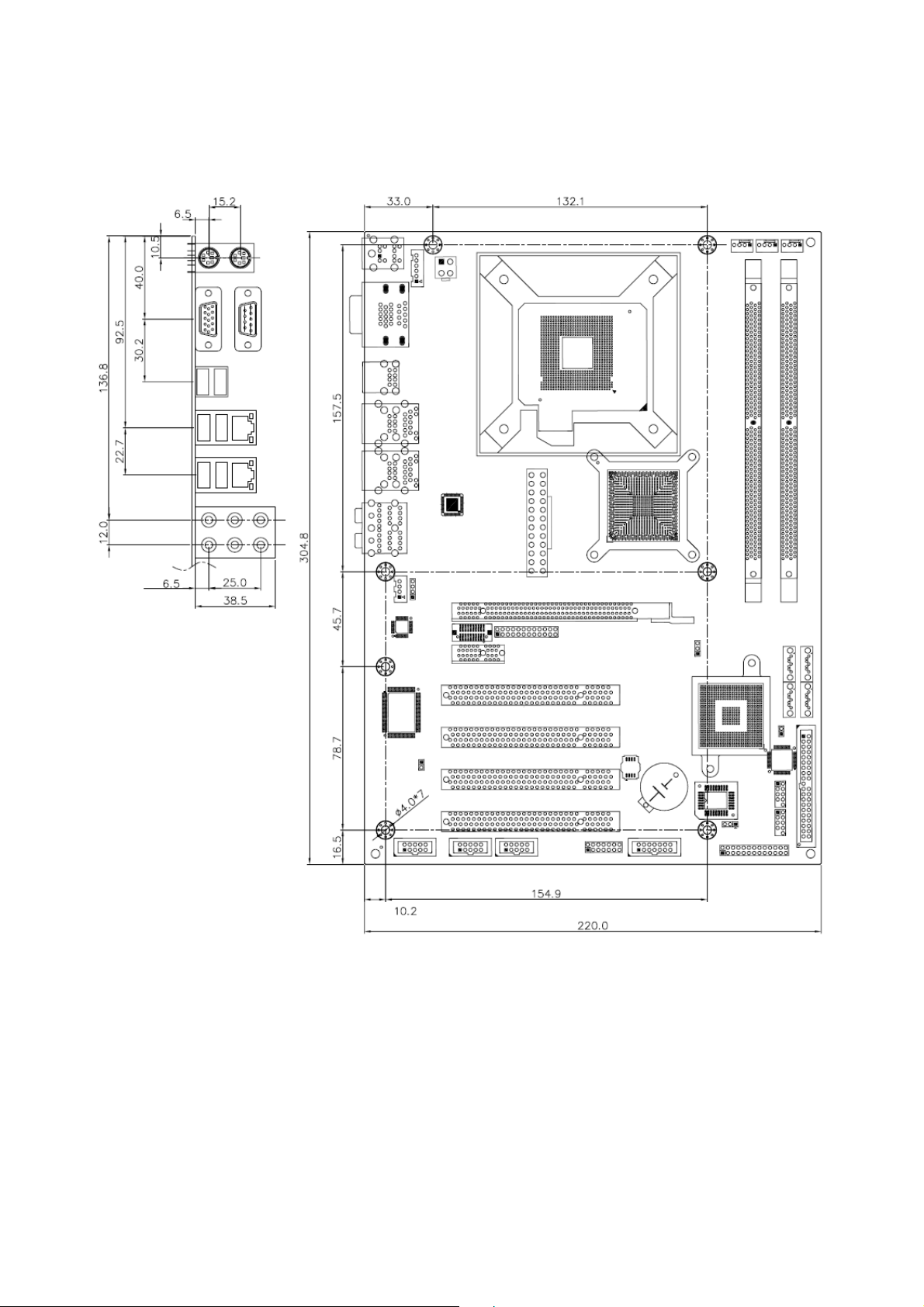
1.5 Dimensions
ADE-9040 User’s Manual
13 / 55
Unit: mm
Page 14

ADE-9040 User’s Manual
CHAPTER 2
14 / 55
Page 15
ADE-9040 User’s Manual
2. Hardware Configuration Setting
This chapter gives the definitions and shows the positions of jumpers, headers and
connectors. All of the configuration jumpers on ADE-9040 are in the proper position. The
default settings shipped from factory are marked with an asterisk ().
In general, jumpers on the ATX Main Board are used to select options for certain features.
Some of the jumpers are designed to be user-configurable, allowing for system
enhancement. The others are for testing purpose only and should not be altered. To select
any option, cover the jumper cap over (SHORT) or remove (NC) it from the jumper pins
according to the following instructions. Here, NC stands for “Not Connect”.
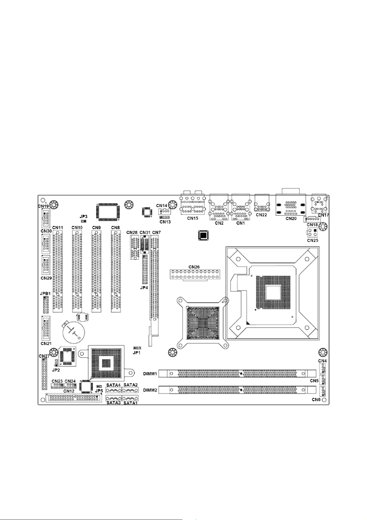
2.1 Board Layout
15 / 55
Page 16

ADE-9040 User’s Manual
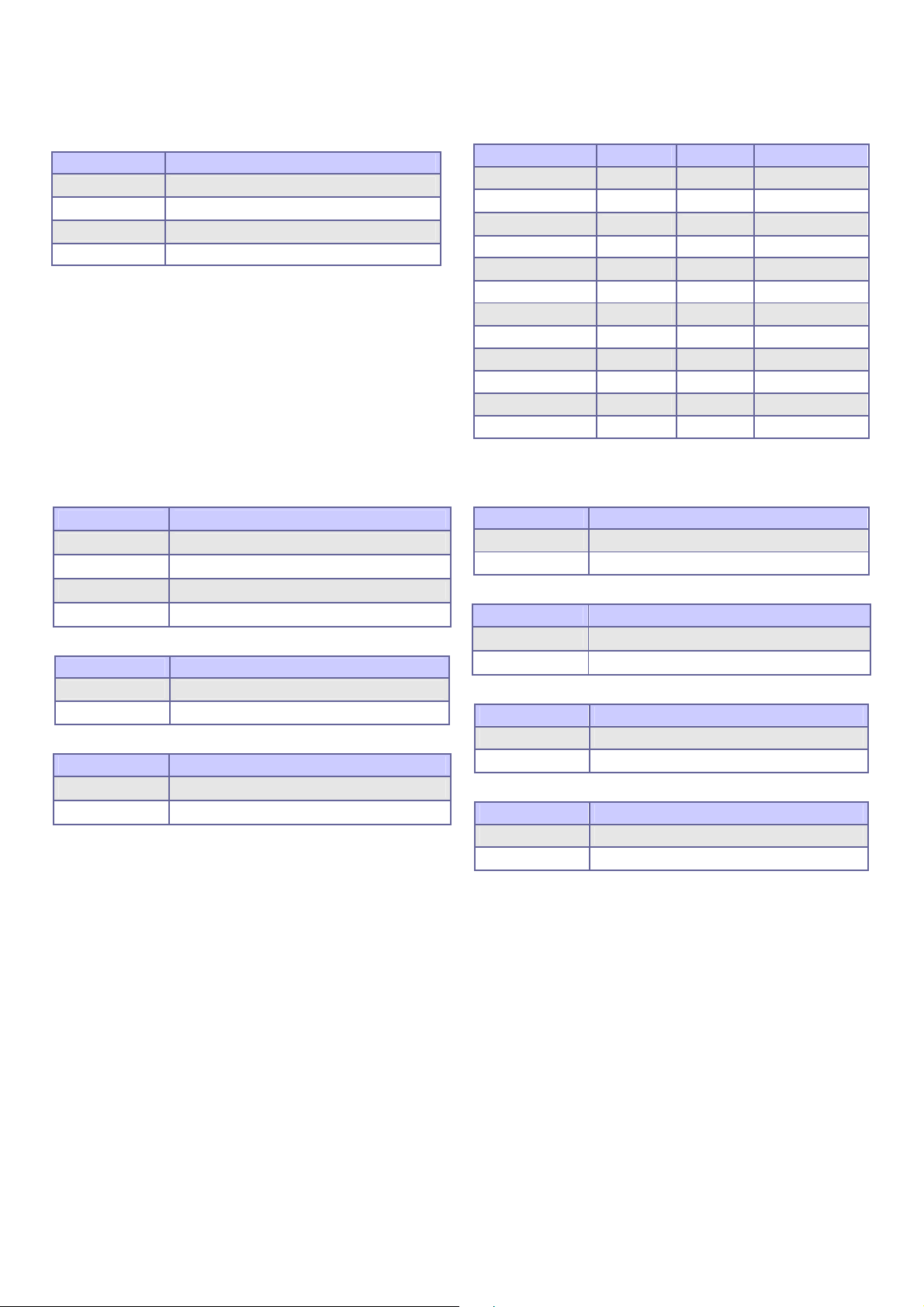
2.2 Jumpers & Connectors
JUMPERS FUNCTION REMARK
JP1
JP2
JP3
JP4
JP5
JPB1
RTC CMOS clear select 1 x 3 header
BIOS write protect 1 x 3 header
AT/ATX power select 1 x 2 header
DVI select 2 x 12 header
PATA select 1 x 2 header
COM4 RS-232/422/485 select 2 x 7 header
CONNECTORS FUNCTION REMARK
CN1, CN2
CN4
CN5
CN6
CN7
CN8, CN9,
USB 2/3/4/5 & RJ-45 LAN 1/2 connector
CPU fan connector 1 x 4 wafer
System fan connector 1 x 4 wafer
Chassis fan connector 1 x 4 wafer
PCI-Express x16 connector
PCI connector 1, 2, 3 & 4
CN10, CN11
CN12
Primary IDE connector 2 x 20 header
CN13
CN14
CN15
CN17
CN18
CN19
CN20
CN21
CN22
CN23, CN24
CN25
CN26
CN27
CN28
CN29, CN30
CD-In from CD-ROM connector 1 x 4 header
Extend Line-out connector 1 x 4 wafer
Audio connector Audio jack
PS/2 keyboard & mouse connector
Extend keyboard & mouse connector 1 x 6 header
Digital IO connector 2 x 5 header
D-sub 15-pin VGA & D-sub 9-pin serial port 1
connectors
Serial port 4 connector 2 x 7 header
USB 0 & 1 connectors
USB 6, 7 & 8, 9 connectors 2 x 5 header
4-pin A TX power connector
24-pin ATX power connector
Front panel connector
PCI Express x1 connector 2 x 13 header
Serial port 3 & 2 connectors
CN31
DIMM1, DIMM2
SATA1, SATA2
SATA3, SATA4
DVI connector
240-pin DDR2 DIMM socket
Serial ATA connector 1, 2
Serial ATA connector 3, 4
16 / 55
Page 17

ADE-9040 User’s Manual
2.3 Jumpers/Connectors Setting
2.3.1 RTC Clear CMOS (JP1) 2.3.2 BIOS Write Protect (JP2)
PIN No. Description
1-2 Normal operation
2-3 Clear CMOS
PIN No. Description
1-2 BIOS write disabled
2-3 BIOS write enabled
2.3.3 AT/ATX Power Select (JP3) 2.3.4 DVI Select (JP4)
PIN No. Description
Open ATX Power
1-2 AT Power
Item. Description
Open PCI Express x16 Display
DVI
1-2, 3-4, 5-6, 7-8,9-10,11-12, 13-14,
15-16, 17-18, 19-20,21-22,23-24 short
2.3.5 P-ATA Select (JP5) 2.3.6 COM2 RS-232/422/485 Select (JPB1)
PIN No. Description
Open P-ATA enabled
1-2 P-ATA disabled
PIN No. RS-232 RS-422 RS-485
1-2 OFF ON (Term.) ON (Term.)
3-4 OFF ON (Term.) ON (Term.)
5-6 OFF OFF ON
7-8 OFF ON OFF
9-10 OFF ON ON
11-12 ON OFF OFF
13-14 OFF OFF ON
2.3.7 USB 2/3/4/5/0/1 & LAN1/2 Connectors (CN1, CN2, CN22)
LAN 1/2
PIN No. Description PIN No. Description
1 TX+ 5 NC
2 TX- 6 RX3 RX+ 7 NC
4 NC 8 NC
2.3.8 Internal USB 6/7/8/9 Connectors (CN23,
CN24)
PIN No. Description PIN No. Description
1 +5V 6 USBP7+/9+
2 +5V 7 Ground
3 USBP6-/8- 8 Ground
4 USBP7-/9- 9 NC
5 USBP6+/8+ 10 NC
PIN No. Description PIN No. Description
1 +5 V (fused) 5 +5 V (fused)
2 USBP0-/2-/4- 6 USBP1-/3-/53 USBP0+/2+/4- 7 USBP1+/3+/5+
4 Ground 8 Ground
2.3.9 CPU/System/Chassis Fan Connector
(CN4, CN5, CN6)
PIN No. Description
1 Ground
2 +12V
3 Fan Status Signal
4 Fan Speed Control
USB 0/1/2/3/4/5
2.3.10 CD-In from CD-ROM (CN13) 2.3.11 Extend Line-out Connector (CN14)
PIN No. Description
1 CD-L
2 CD-Ground
3 CD-Ground
4 CD-R
PIN No. Description
1 LINE_OUT_L
2 GND
3 GND
4 LINE_OUT_R
17 / 55
Page 18

ADE-9040 User’s Manual
2.3.12 Audio Connector (CN15) 2.3.13 PS/2 Keyboard & Mouse Connector
(CN17)
PIN No. Description PIN No. Description
1(Orange) Central out 4(Blue) Line-in
2(Black) Surround out 5(Green) Line-out
3(Gray) Side out 6(Red) Mic-in
PIN No. Description PIN No. Description
1 Keyboard Data 7 Mouse Data
2 NC 8 NC
3 Ground 9 Ground
4 +5V 10 +5V
5 Keyboard Clock 11 Mouse Clock
6 NC 12 NC
2.3.14 Extend Keyboard & Mouse Connector
(CN18)
PIN No. Description
1 Mouse Clock
2 Mouse Data
3 Keyboard Clock
4 Keyboard Data
5 Ground
6 +5V
2.3.16 VGA & Serial Port 1 Connector (CN20)
COM1
PIN No. Description
1 Data Carrier Detect
2 Received Data
3 Transmit Data
4 Data Terminal Ready
5 Ground
6 Data Set Ready
7 Request To Send
8 Clear To Send
9 Ring Indicator
10 Not used
2.3.15 Digital I/O Connector (CN19)
Description PIN No. PIN No. Description
ISO_I1 2 1 EXT_VDD
ISO_I2 4 3 ISO_O1
ISO_I3 6 5 ISO_O2
ISO_I4 8 7 ISO_O3
EXT_VSS 10 9 ISO_O4
Description PIN No. PIN No. Description
Green Signal 2 1 Red Signal
NC 4 3 Blue Signal
Ground 6 5 Ground
Ground 8 7 Ground
Ground 10 9 +5V
DCC_DATA 12 11 NC
VSYNC 14 13 HSYNC
15 DCC_CLK
VGA
2.3.17 Serial Port 4 Connector (CN21) 2.3.18 Serial Port 3 & 2 Connectors (CN29,
CN30)
Description PIN No. PIN No. Description
DCD 1 2 DSR
RXD 3 4 RTS
TXD 5 6 CTS
DTR 7 8 RI
Ground 9 10 Ground
TX+ 11 12 TX-
RX+ 13 14 RX-
Description PIN No. PIN No. Description
DCD 1 2 DSR
RXD 3 4 RTS
TXD 5 6 CTS
DTR 7 8 RI
Ground 9 10 Ground
18 / 55
Page 19
ADE-9040 User’s Manual
2.3.19 4-pin ATX Power Connector (CN25) 2.3.20 24-pin ATX Power Connector (CN26)
PIN No. Description
1 GND
2 GND
3 +12V
4 +12V
Description PIN No. PIN No. Description
+3.3V 13 1 +3.3V
-12V 14 2 +3.3V
Ground 15 3 Ground
PS_ON 16 4 +5V
Ground 17 5 Ground
Ground 18 6 +5V
Ground 19 7 Ground
-5V 20 8 PW_OK
+5V 21 9 5VSB
+5V 22 10 +12V
+5V 23 11 +12V
Ground 24 12 +3.3V
2.3.21 Front Panel Connector (CN27)
IrDA
PIN No. Signal Description
1 +5V
5 IRRX
7 Ground
9 IRTX
System Reset
PIN No. Signal Description
2 Reset
4 Ground
External Speaker
PIN No. Signal Description
8 Speaker
14 +5V
IDE Active LED
PIN No. Signal Description
13 +5V (Pull-up for HDD LED)
15 HDD active# (LED cathode terminal)
System Power On LED
PIN No. Signal Description
18 +5V
22 Power On
System Power On Switch
PIN No. Signal Description
23 Power button control signal
25 Ground
Keyboard Lock
PIN No. Signal Description
24 Keyboard lock
26 Ground
19 / 55
Page 20

ADE-9040 User’s Manual
2.3.22 DVI Connector (CN31)
Description PIN No. PIN No. Description
HPDET 1 2 Ground
Ground 3 4 DVIDATA
TDC0# 5 6 DVICLK
TDC0 7 8 Ground
Ground 9 10 TLC#
TDC1# 11 12 TLC
TDC1 13 14 Ground
Ground 15 16 Ground
TDC2# 17 18 Ground
TDC2 19 20 +5V
Signal Type Description
TDC0,TDC0# O
TDC1,TDC1# O
TDC2,TDC2# O
HPDET I
DVIDATA I/O
DVICLK I/O
TLC,TLC# O
DVI Data Channel 0 Output: These pins provide the DVI differential
output for data channel 0 (Blue).
DVI Data Channel 1 Output: These pins provide the DVI differential
output for data channel 1 (Green).
DVI Data Channel 2 Output: These pins provide the DVI differential
output for data channel 2 (Red).
Hot Plug Detect (internal pull-down): This input determines whether the
DVI is connected to a DVI monitor. When terminated\, the monitor is
required to apply a voltage greater than 2.4 volts. Changes on the status of
this pin will be relayed to the graphics controller via the P-OUT/TLDET* or
GPIO(1)/TLDET* pin pulling low.
DVI I2C Data: This signal is used as the I2C DOC clock for a digital display
connector (i.e. TV-Out Encoder, TMDS transmitter ). This signal is
tri-stated during a hard reset.
DVI DOC Clock: This signal is used as the DOC clock for a digital display
connector (i.e. primary digital monitor). This signal is tri-stated during a
hard reset.
DVI Clock Output: These pins provide the differential clock outputs to the
DVI interface corresponding a data on TDC(0:2) output s.
2.3.23 Serial ATA 1/2/3/4 Connectors (SATA1,
SATA2, SATA3, SATA4)
These SATA connectors support Serial ATA 300. Each
SATA connector can only support one serial ATA device.
Note: With most storage devices, there is a power cable
that you need attach to a power source (power
supply).
20 / 55
Page 21

ADE-9040 User’s Manual
CHAPTER 3
21 / 55
Page 22

ADE-9040 User’s Manual
3. System Installation
This chapter provides you with instructions on how to setup your system. The additional
information shows you how to install CPU/ FAN and memory.
3.1 Intel® µFC-LGA775 Processor
3.1.1 Installing Intel® Core™ 2 Duo / Pentium® 4 / Celeron® D CPU
• The board comes with a surface mount LGA775 socket designed for the Intel®
Pentium® 4 processor in the 775-land package.
• Remove the plastic cap to install the µFC-LGA 775 Pentium 4 CPU.
• Unlock the socket by pressing the metal lever sideways to lift it up, and open the load
plate. (1, 2, 3, 4)
• Position the CPU above the socket and the gold triangular mark on the CPU must
align with pin 1 of the CPU socket. Then Insert the CPU gently seated in place.
• Close the load plate and push it back to the original position. (5, 6, 7)
1
2
3
4
6
Metal level Plastic cap Pin 1 of the socket Gold triangular mark
Load plate
Note:
Do not force the CPU into the socket. It may bend the pins and damage the CPU.
P
5
22 / 55
Page 23

ADE-9040 User’s Manual
3.1.2 Installing Intel µFC-LGA 775 CPU Fan, and Heat Sink
• The Intel µFC-LGA 775 CPU heat sink and fan assembly comes in a push-pin design
and requires no tool to install.
• Place the fan with heat sink right above the CPU and make sure four pins matching
the holes of the board. (8, 9)
• Press all push-pins down and rotate them to lock. (Please check the rear side of the
board.)
• Place the CPU fan connector.
9
8
Push-pin
Board’s hole CPU fan connector
3.1.3 Removing CPU
• Disconnect the CPU fan connector.
• Remove the CPU fan and heat sink first.
• Unlock the Intel µFC-LGA 775 Pentium 4 processor.
• Carefully lift up the existing CPU to remove it from the socket.
• Follow the steps of installing a CPU to change to another one.
Warning: For a safety landing, avoid leaving prongs on hard surface.
Instructions:Smear thermal grease on the top of the CPU. Lower the CPU fan onto the
CPU/CPU socket and secure it using the attachments or screws provided
on the fan. Finally, attach the fan power cable to the CPUFAN adapter. For
more details on this, go to http://www.intel.com
23 / 55
Page 24

ADE-9040 User’s Manual
3.2 Main Memory
ADE-9040 provides 2 DIMMs (240-pin Dual In-line Memory Module) to support 1.8V
DDRAM (Synchronized DRAM) as on-board main memory. The maximum memory size is
256 MB ~ 4 GB with using 256MB/512MB/1GB technology. Supports up to 2 double sided
DIMMs at DDR2 533/667/800MHz. The memory architecture adopts 128-bit data interface
to support for x8 and x16 DDRAM(DDR2) device width. In addition, it only supports
Non-ECC memory.
For system compatibility and stability, don’t use memory module without brand. You can
also use the single or double-side DIMM .The two DIMMs can be out of order. You can
install different size of DDRAM module on DIMM1, DIMM2 or all to boot up system.
Without out the contact and lock integrity of memory module with socket, it will impact on
the system reliability. Follow normal procedure to install your DDRAM module into memory
socket. Before locking, make sure that the module has been fully inserted into the DIMM
slot.
NOTE: For maintaining system stability, do not change any of DDR2 memory parameters in
BIOS setup to upgrade your system performance without acquiring technical
information.
24 / 55
Page 25

ADE-9040 User’s Manual
3.3 Installing the ATX Mother Board
To install your ADE-9040 into standard chassis or proprietary environment, you need to
perform the following steps:
1. Check all jumpers setting on proper position
2. Install and configure CPU and memory module on right position
3. Place ADE-9040 into the dedicated position in your system
4. Attach cables to existing peripheral devices and secure it
NOTE: Please refer section 3.4 to install display and Ethernet drivers and setup your
system.
WARNING: Please ensure that your ATX Main Board properly inserted and fixed by
mechanism. Otherwise, the system might be unstable or do not work from
bad contact of golden finger.
3.4.1 Dual Marvell Gigabit Ethernet Controllers
Dual Marvell Gigabit Ethernet 10/100/1000BASE-TX controllers by PCI Express.
The ADE-9040 provides dual LED indicators on RJ-45 connectors to show LAN interface
status. These messages will give you a guide for troubleshooting.
Yellow LED indicates transmit and receive activity.
Blinking: indicates transmit/receive activity
On: indicates no activity but link is valid
Off: link is invalid
Green LED indicates Link speed
On: link speed at 1000Mbps
On: link speed at 100Mbps
Off: link speed at 10Mbps
3.4.2 Drivers Support
ADE-9040 provide on CD-Title to support on-board VGA and Ethernet device drivers in
various operating systems. Before installing the device drivers, please see the reference
files in each sub-directory. You cannot install drivers from CD-Title directly.
Intel Q965 Chipset Integrated Graphics supports Win2000, XP, Win2003 and 64bit
Windows environment.
Intel Q965 & ICH8(R) Chipset Driver supports Win2000, XP, Win2003 and 64bit Windows
environment.
Dual Marvell Gigabit Ethernet Controllers support Win2000, XP, Win2003, and 64 bit
Windows environment.
25 / 55
Page 26

ADE-9040 User’s Manual
CHAPTER 4
26 / 55
Page 27

ADE-9040 User’s Manual
4. BIOS Setup
4.1 Entering Setup
AMI BIOS has a built-in setup program that allows users to modify the basic system
configuration. This information is stored in CMOS RAM whose power is supplied by a
battery so that it can retain the setup information even when the power is turned off. Press
Delete when you Power on or Reboot the computer system. (i.e. After the logo appears at
the center of the screen, please press Delete to enter the BIOS setup program). In the
BIOS, make sure that everything is working fine before you try to optimize it for maximum
performance.
4.1.1 Main Menu
When you enter the AMI CMOS Setup Utility, the Main will appear on the screen. The Main
allows you to select several configuration options. Use the left/right arrow keys to highlight
a particular configuration screen from the top menu bar or use the down arrow key to
access and configure the information below.
4.1.1.1 System Time / System Date
Use this option to change the system time and date. The date must be entered in
MM/DD/YY format. The time is entered in HH:MM:SS format.
27 / 55
Page 28
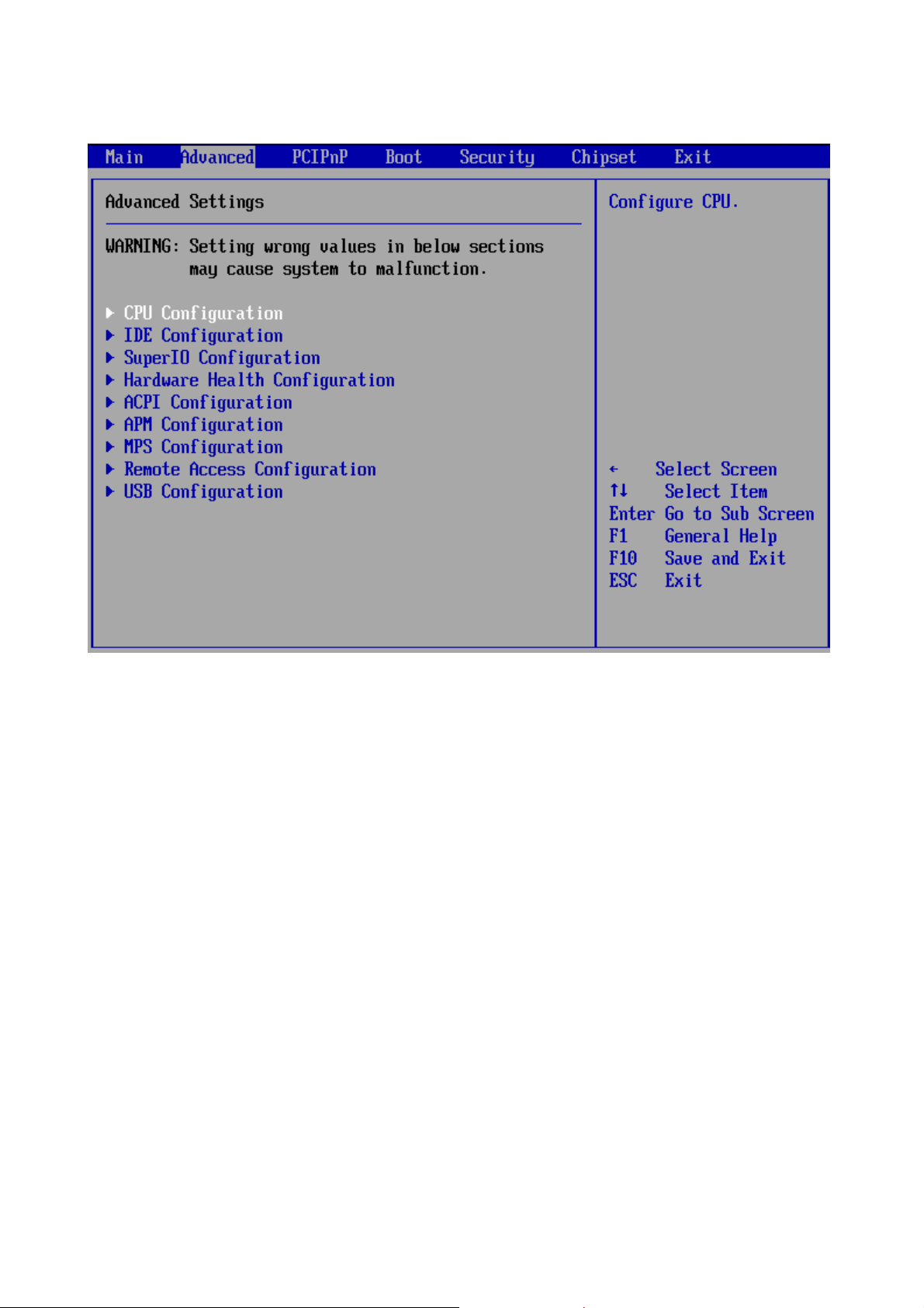
4.1.2 Advanced Setting
ADE-9040 User’s Manual
28 / 55
Page 29

ADE-9040 User’s Manual
4.1.2.1 CPU Configuration
The CPU Configuration setup screen varies depending on the installed processor.
4.1.2.1.1 Max CPUID Value Limit
The Intel® Processor Identification Utility requires the 'Max CPUID Value Limit' in the
system BIOS to be disabled for proper processor identification. Once processor
identification has taken place, the option can be re-enabled if desired.
4.1.2.1.2 Execute Disable Bit
A feature designed to stop buffer overflow attacks against the operating system. Buffer
overflow attacks are one of the most common tactics used to attack personal computers.
The processor prevents the execution of code in data-only memory pages while enabled
and will not restrict code execution in any memory area if disabled. This makes the
processor more vulnerable to buffer overflow attacks
4.1.2.1.3 Intel ® SpeedStep (tm) tech.
Intel (R) SpeedStep(tm) tech. is Intel’s new power saving technology. Processor can switch
between multiple frequency and voltage points to enable power savings. If you select [Auto],
you need to set the “Power Schemes” as “Portable/Laptop” to enable this function. This
option will be hidden if the current CPU does not support Intel SpeedStep(tm) tech..
4.1.2.1.4 Intel C-State tech
Specific C-State supports. Standard = Conventional C-State. Enhanced = Enhanced
C-State.
29 / 55
Page 30

4.1.2.2 IDE Configuration
ADE-9040 User’s Manual
4.1.2.2.1 SATA#1 Configuration
Option: [Disabled], [Enhanced].
4.1.2.2.2 Configure SATA#1 as
Option: [IDE], [RAID]
4.1.2.2.3 Primary/Secondary IDE Master/Slave
Select one of the hard disk drives to configure it. Press <Enter> to access its the sub menu.
The options on the sub menu are described in the following sections.
4.1.2.2.4 Hard Disk Write Protect
Set this option to protect the hard disk drive from being overwritten. The Optimal and
Fail-Safe default setting is Disabled.
4.1.2.2.5 IDE Detect Time Out (Sec)
Set this option to stop the AMIBIOS from searching for IDE devices within the specified
number of seconds. Basically, this allows you to fine-tune the settings to allow for faster
boot times. Adjust this setting until a suitable timing that can detect all IDE disk drives
attached is found.
The options: 0, 5, 10, 15, 20, 25, 30, 35 sec.
30 / 55
Page 31

ADE-9040 User’s Manual
4.1.2.2.6 ATA(PI) 80Pin Cable Detection
Set this option to select the method used to detect the ATA (PI) 80 pin cable. The Optimal
and Fail-Safe setting is Host & Device.
Item Description
Host & Device
Set this value to use both the motherboard onboard IDE controller and IDE disk drive to detect the
type of IDE cable used. This is the default setting.
Host
Device
Set this value to use motherboard onboard IDE controller to detect the type of IDE cable used.
Set this value to use IDE disk drive to detect the type of IDE cable used.
31 / 55
Page 32

4.1.2.3 Super IO Configuration
ADE-9040 User’s Manual
32 / 55
Page 33

ADE-9040 User’s Manual
4.1.2.3.1 Serial Port1/2 Address
This option specifies the base I/O port address and Interrupt Request address of serial port
1/2. The Optimal setting is 3F8/IRQ4. The Fail-Safe default setting is Disabled.
Item Description
Disabled
Set this value to prevent the serial port from accessing any system resources. When
this option is set to Disabled, the serial port physically becomes unavailable.
Set this value to allow the serial port to use 3F8 as its I/O port address and IRQ 4 for the
interrupt address. This is the default setting. The majority of serial port 1 or COM1 ports
3F8/IRQ4
2F8/IRQ3
3E8/IRQ4
2E8/IRQ3
on computer systems use IRQ4 and I/O Port 3F8 as the standard setting. The most
common serial device connected to this port is a mouse. If the system will not use a
serial device, it is best to set this port to Disabled.
Set this value to allow the serial port to use 2F8 as its I/O port address and IRQ 3 for the
interrupt address. If the system will not use a serial device, it is best to set this port to
Disabled.
Set this value to allow the serial port to use 3E8 as its I/O port address and IRQ 4 for the
interrupt address. If the system will not use a serial device, it is best to set this port to
Disabled.
Set this value to allow the serial port to use 2E8 as its I/O port address and IRQ 3 for the
interrupt address. If the system will not use a serial device, it is best to set this port to
Disabled.
4.1.2.3.2 Serial Port2 Mode
Allows BIOS to select mode for Serial Port2.
4.1.2.3.3 Restore on AC Power Loss by IO
This item allows you to select if you want to power on the system after power failure.
Option: [Power On], [Power Off], [Last state].
4.1.2.3.4 Serial Port3/4 Address
Allows BIOS to select serial port 3/4 base addresses.
4.1.2.3.5 Serial Port3/4 IRQ
Allows BIOS to select serial port 3/4 IRQ.
33 / 55
Page 34

4.1.2.4 Hardware Health Configuration
ADE-9040 User’s Manual
4.1.2.4.1 H/W Health Function
Enables Hardware Health Monitoring Device.
4.1.2.4.2 FAN 1 Mode Setting
This item allows you to set fan speed control mode.
Option: [Full On mode], [Automatic mode].
4.1.2.4.3 Temperature 1 Limit of Start
Fan spins in a start PWM value when temp exceeds a start limit
Min=0℃, Max=127℃, Please input Dec number:
4.1.2.4.4 Fan 1 Start PWM
Fan start PWM value.
Min=0, Max=127, Please input Dec number.
4.1.2.4.5 Slope PWM 1
The PWM value is subject to the temperature inputs by linear changing.
4.1.2.4.6 FAN 2 Mode Setting
This item allows you to set fan speed control mode.
Option: [Full On mode], [Automatic mode].
4.1.2.4.7 Temperature 2 Limit of Start
Fan spins in a start PWM value when temp exceeds a start limit
Min=0℃, Max=127℃, Please input Dec number:
34 / 55
Page 35

ADE-9040 User’s Manual
4.1.2.4.8 Fan 2 Start PWM
Fan start PWM value.
Min=0, Max=127, Please input Dec number:.
4.1.2.4.9 Slope PWM 2
The PWM value is subject to the temperature inputs by linear changing.
35 / 55
Page 36

4.1.2.5 ACPI Configuration
ADE-9040 User’s Manual
4.1.2.5.1 ACPI Aware O/S
Set this value to allow the system to utilize the Intel ACPI (Advanced Configuration and
Power Interface) specification.
Item Description
This setting should be set if the operating system in use does not comply with the ACPI
No
Yes
(Advanced Configuration and Power Interface) specification. DOS®, Windows 3.x®,
and Windows NT® are examples of non-ACPI aware operating systems.
This setting should be set if the operating system complies with the ACPI (Advanced
Configuration and Power Interface) specification. This is the default setting. Windows
95®, Windows 98® and Windows 2000® are examples of ACPI aware operating
systems.
36 / 55
Page 37

4.1.2.6 APM Configuration
ADE-9040 User’s Manual
4.1.2.6.1 Power Management/APM
Set this value to allow Power Management/APM support.
4.1.2.6.2 Video Power Down Mode
This option specifies the length of time the system waits before it enters suspend mode.
The options: Disabled, 1, 5, 10 Min.
4.1.2.6.3 Hard Disk Power Down Mode
This option specifies the power conserving state that the hard disk drive enters after the
specified period of hard drive inactivity has expired.
The options: Disabled, Standby, Suspend.
4.1.2.6.4 Suspend Time Out
Go into Suspend in the specified time.
4.1.2.6.5 Throttle Slow Clock Ratio
In a power management state, the BIOS can throttle the CPU clock to reduce power
consumption. For example, a throttle ratio of 50% means the clock is turned off half of its
normal operational time.
The options: 87.5%, 75.0%, 62.5%, 50%, 37.5%, 25%, 12.5%.
4.1.2.6.6 Keyboard & PS/2 Mouse
Monitor KBC Ports 60/64.
37 / 55
Page 38

ADE-9040 User’s Manual
4.1.2.6.7 Power Button Mode
This option specifies how the externally mounted power button on the front of the computer
chassis is used.
The options: On/Off, Standby, Suspend.
4.1.2.6.8 Resume On Ring
Disable/Enable RI to generate a wake event.
4.1.2.6.9 Resume On LAN
Disable/Enable LAN GPI to generate a wake event.
4.1.2.6.10 Resume On PME#
Disable/Enable PME to generate a wake event.
4.1.2.6.11 Resume On RTC Alarm
Disable/Enable RTC to generate a wake event.
38 / 55
Page 39

4.1.2.7 MPS Configuration
ADE-9040 User’s Manual
Select MPS Revision.
39 / 55
Page 40

4.1.2.8 Remote Access Configuration
ADE-9040 User’s Manual
4.1.2.8.1 Remote Access
You can disable or enable the BIOS remote access feature here.
4.1.2.8.2 Serial Port Number
Select serial port for console redirection. Make sure the selected port is enabled.
4.1.2.8.3 Flow Control
Select Flow Control for console redirection.
4.1.2.8.4 Redirection after BIOS POS
Disable: Turns off the redirection after POST Boot Loader: Redirection is active
during POST and during Boot Loader. Always: Redirection is always active.
(Some OSs may not work if set to Always)
[Enabled] - keep it, [Disabled]- deactivate
4.1.2.8.5 Terminal Type
Select the target terminal type.
4.1.2.8.6 VT-UTF8 Combo Key Support
Enable VT-UTF8 Combination Key Support for ANSI/VT100 terminals.
4.1.2.8.7 Sredir Memory Display Delay
Gives the delay in seconds to display memory information.
40 / 55
Page 41

4.1.2.9 USB Configuration
ADE-9040 User’s Manual
4.1.2.9.1 Legacy USB Support
Legacy USB Support refers to the USB mouse and USB keyboard support. Normally if this
option is not enabled, any attached USB mouse or USB keyboard will not become available
until a USB compatible operating system is fully booted with all USB drivers loaded. When
this option is enabled, any attached USB mouse or USB keyboard can
control the system even when there is no USB drivers loaded on the system. Set this value
to enable or disable the Legacy USB Support. The Optimal and Fail-Safe default setting is
Disabled.
4.1.2.9.2 Port 64/60 Emulation
Enables I/O port 60h/64h emulation support. This should be enabled for the complete
USB keyboard legacy support for non-USB aware OSes.
4.1.2.9.3 USB 2.0 Controller Mode
Configures the USB 2.0 controller in HiSpeed (480Mbps) or FullSpeed (12Mbps).
4.1.2.9.4 BIOS EHCI Hand-Off
This is a workaround for OSes without EHCI hand-off support. The EHCI ownership change
should claim by EHCI driver.
41 / 55
Page 42

4.1.2.9.5 USB Mass Storage Device Configuration
ADE-9040 User’s Manual
4.1.2.9.5.1 Emulation Type
If Auto, USB devices less than 530MB will be emulated as Floppy and remaining as hard
drive. Forced FDD option can be used to force a HDD formatted drive to boot as FDD (Ex.
ZIP drive)
42 / 55
Page 43

4.1.3 Advanced PCI/PnP Setting
ADE-9040 User’s Manual
43 / 55
Page 44

ADE-9040 User’s Manual
4.1.3.1 Clear NVRAM
Clear NVRAM during System Boot.
4.1.3.2 Plug & Play O/S
Set this value to allow the system to modify the settings for Plug and Play operating system
support.
Item Description
No
The No setting is for operating systems that do not meet the Plug and Play
specifications. It allows the BIOS to configure all the devices in the system.
Yes
The Yes setting allows the operating system to change the interrupt, I/O, and DMA
settings. Set this option if the system is running Plug and Play aware operating systems.
4.1.3.3 PCI Latency Timer
Set this value to allow the PCI Latency Timer to be adjusted. This option sets the latency of
all PCI devices on the PCI bus.
The options: 32, 64, 96, 128, 160, 192, 224, 248 PCI clock cycles.
4.1.3.4 Allocate IRQ to PCI VGA
Set this value to allow or restrict the system from giving the VGA adapter card an interrupt
address.
4.1.3.5 Palette Snooping
Set this value to allow the system to modify the Palette Snooping settings.
Item Description
Disabled
Enabled
This is the default setting and should not be changed unless the VGA card manufacturer
requires Palette Snooping to be Enabled.
This setting informs the PCI devices that an ISA based Graphics device is installed in
the system. It does this so the ISA based Graphics card will function correctly. This does
not necessarily indicate a physical ISA adapter card. The graphics chipset can be
mounted on a PCI card. Always check with your adapter card’s manuals first, before
modifying the default settings in the BIOS.
4.1.3.6 PCI IDE BusMaster
Set this value to allow or prevent the use of PCI IDE busmastering.
4.1.3.7 OffBoard PCI/ISA IDE Card
Set this value to allow the OffBoard PCI/ISA IDE Card to be selected.
4.1.3.8 IRQ3/4/5/7/9/10/11/14/15
Set this value to allow the IRQ settings to be modified.
Item Description
Available
Reserved
This setting allows the specified IRQ to be used by a PCI/PnP device.
This setting allows the specified IRQ to be used by a legacy ISA device.
44 / 55
Page 45

4.1.3.9 DMA Channel 0/1/3/5/6/7
Set this value to allow the DMA setting to be modified.
Item Description
Available
This setting allows the specified DMA to be used by PCI/PnP device.
ADE-9040 User’s Manual
Reserved
This setting allows the specified DMA to be used by a legacy ISA device.
4.1.3.10 Reserved Memory Size
Set this value to allow the system to reserve memory that is used by ISA devices
The options: Disabled, 16K, 32K, 64K.
45 / 55
Page 46

4.1.4 Boot Settings
ADE-9040 User’s Manual
46 / 55
Page 47

4.1.4.1 Boot Settings Configuration
ADE-9040 User’s Manual
4.1.4.1.1 Quick Boot
The Optimal and Fail-Safe default setting is Disabled. Allow to set this value to allow the
BIOS to skip certain POST tests to boot faster or disabled to perform all POST tests.
4.1.4.1.2 Quiet Boot
Set this value to allow the boot up screen options to be modified between POST messages
or OEM logo. The Optimal and Fail-Safe default setting is Enabled.
4.1.4.1.3 AddOn ROM Display Mode
Set this option to display add-on ROM (read-only memory) messages.
Item Description
Set this value to allow the computer system to force a third party BIOS to display during
Force BIOS
system boot. This is the default setting.
Set this value to allow the computer system to display the information during system
Keep Current
boot.
4.1.4.1.4 Bootup Num-Lock
Set this value to allow the Number Lock setting to be modified during boot up.
47 / 55
Page 48

ADE-9040 User’s Manual
4.1.4.1.5 Wait For ‘F1’ If Error
Set this value to allow the Wait for ‘F1’ Error setting to be modified.
Item Description
This prevents the to wait on an error for user intervention. This setting should be used if
there is a known reason for a BIOS error to appear. An example would be a system
Disabled
Enabled
administrator must remote boot the system. The computer system does not hav e a
keyboard currently attached. If this setting is set, the system will continue to boot up in
to the operating system. If ‘F1’ is enabled, the system will wait until the BIOS setup is
entered.
Set this value to allow the system BIOS to wait for any error. If an error is detected,
pressing <F1> will enter Setup and the BIOS setting can be adjusted to fix the problem.
This normally happens when upgrading the hardware and not setting the BIOS to
recognize it. This is the default setting.
4.1.4.1.6 Hit ‘DEL’ Message Display
Set this value to allow the Hit “DEL” to enter Setup Message Display to be modified.
4.1.4.1.7 Interrupt 19 Capture
Enabled: Allows option ROMs to trap interrupt 19. This is required by some PCI cards that
provide a ROM based setup utility.
48 / 55
Page 49

4.1.5 Security Settings
ADE-9040 User’s Manual
4.1.5.1 Change Supervisor Password
Indicates whether a supervisor password has been set. If the password has been installed,
Installed displays. If not, Not Installed displays.
4.1.5.2 Change User Password
Indicates whether a user password has been set. If the password has been installed,
Installed displays. If not, Not Installed displays.
4.1.5.3 Clear User Password
Select Clear User Password from the Security Setup menu.
4.1.5.4 Boot Sector Virus Protection
Enable/Disable Boot Sector Virus Protection.
49 / 55
Page 50

4.1.6 Advanced Chipset Settings
ADE-9040 User’s Manual
50 / 55
Page 51

ADE-9040 User’s Manual
4.1.6.1 North Bridge Configuration
You can use this screen to select options for the North Bridge Configuration. Use the up
and down <Arrow> keys to select an item. Use the <Plus> and <Minus> keys to change the
value of the selected option.
Note: The North Bridge Configuration setup screen varies depending on the supported
North Bridge chipset.
4.1.6.1.1 Memory Remap Feature
ENABLE: Allow remapping of overlapped PCI memory above the total physical memory.
DISABLE: Do not allow remapping of memory.
4.1.6.1.2 DRAM Frequency
The item allows you to set the DRAM frequency.
4.1.6.1.3 Configure DRAM Timing by SPD
Select the operating system that is selecting DRAM timing, so select SPD for setting DRAM
timing by SPD.
The choice: [Enable], [Disable]
4.1.6.1.4 Initate Graphic Adapter
Select which graphics controller to use as the primary boot device.
4.1.6.1.5 Internal Graphics Mode Select
Select the amount of system memory used by the internal graphics device.
51 / 55
Page 52

4.1.6.1.6 PEG Port
This item allows you to control the PEG or on-chip VGA.
The choice: [Auto], [Disabled].
ADE-9040 User’s Manual
52 / 55
Page 53

ADE-9040 User’s Manual
4.1.6.2 South Bridge Configuration
You can use this screen to select options for the South Bridge Configuration. South Bridge
is a chipset on the motherboard that controls the basic I/O functions, USB ports, audio
functions, modem functions, IDE channels, and PCI slots. Use the up and down <Arrow>
keys to select an item. Use the <Plus> and <Minus> keys to change the value
of the selected option.
Note: The South Bridge Configuration setup screen varies depending on the supported
South Bridge chipset.
4.1.6.2.1 USB Functions
This item allows you to active USB ports.
4.1.6.2.2 USB 2.0 Controller
Select “Enabled” if your system contains a Universal Serial Bus 2.0 (USB 2.0) controller
and you have USB peripherals.
The choice: Enabled, Disabled.
4.1.6.2.3 HDA Controller
This item allows you to select the chipset family to support High Definition Audio Controller.
The choice: Disabled, Enabled.
53 / 55
Page 54

ADE-9040 User’s Manual
4.1.6.2.4 Onboard Giga LAN 1/2
Select “Enabled” if your system has a LAN device installed on the system board and you
wish to use it.
The choice: Enabled, Disabled
4.1.6.2.5 SLP_S4# Min. Assertion Width
The item allows you to select the assertion width of SLP_S4#.
The choice: 4 to 5 sec., 3 to 4 sec., 2 to 3 sec, 1 to 2 sec.
54 / 55
Page 55

4.1.7 Exit Options
ADE-9040 User’s Manual
4.1.7.1 Save Changes and Exit
When you have completed the system configuration changes, select this option to leave
Setup and reboot the computer so the new system configuration parameters can take
effect.
4.1.7.2 Discard Changes and Exit
Select this option to quit Setup without making any permanent changes to the system
configuration.
4.1.7.3 Discard Changes
Select Discard Changes from the Exit menu and press <Enter>.
4.1.7.4 Load Optimal Defaults
Load Optimal Default values for all the setup questions. F9 key can be used for this
operation.
4.1.7.5 Load Failsafe Defaults
Load Failsafe Default values for all the setup questions. F8 key can be used for this
operation
55 / 55
 Loading...