

Page 1

AC450NX Rack Server System Product Guide
Order Number: 702026-003
Page 2

Information in this doc um ent is provided in connection wi t h Intel products. No license, express or implied, by estoppel or
otherwise, to any intell ectual property rights is granted by this document. E x cept as provided in Intel’s Terms and
Conditions of Sale for such products, Intel assumes no liability whatsoever, and I nt el dis claims any express or implied
warranty, relating to sale and/or use of Intel products including liability or warranties relating to fitness for a partic ular
purpose, merchantability, or infringement of any patent, copyright or other int ellec tual property right. Intel products are not
designed, intended or authorized for use in any medical, life saving, or life sustai ni ng appl i cations or for any other
application in which the fai l ure of the Intel product could c reat e a situation where personal injury or deat h m ay occur. Intel
may make changes to specifications and product descriptions at any tim e, without notice. No part of this document may be
copied or reproduced in any form or by any m eans without prior consent of Intel.
†
Third party brands and names are property of their respective owners.
Copyright 1998-1999, Intel Corporation. All Rights Reserved.
Page 3

Quick Reference and Conventions
For translated warnings, see Appendix C, “Warnings”
Part I: User’s Guide
1 Introduction to the High-performance Server
2 On-site Installation: Installing the Server
3 Power-on Self Test: Description/Running
4 Setup Utility: When to Run
5 System Setup Utility: When to Run
6 SCSI Configuration Utility
7 Emergency Management Port Console: How to Use
8 FRU and SDR Load Utility: When to Run
9 Hot-swappable Fans: Hot Swapping
10 Hot-swappable SCSI Hard Disk Drives: Installing/Hot Swapping
11 Hot-swappable Power Supplies: Hot Swapping
Part II: Service Technician’s Guide
Safety Guidelines
12 Server Covers: Removing/Reinstalling
13 Server Components: Removing/Reinstalling
14 Removable Media Drives: Installing/Removing/Replacing
15 Midplane: Description/Voltages
16 Peripheral Bay Backplane: Description
17 PHP I/O Baseboard: Description/Setting Configuration Jumpers
18 CPU Baseboard: Description/Setting Configuration Jumpers
iii
Page 4

AC450NX Rack Server System Product Guide
19 Memory Modules: Description/Adding Memory
20 Power System: Description/Calculating Power Usage
21 Back-up Battery: Replacing/Disposing
22 Solving Problems: Troubleshooting/Error Messages
23 Front Panel: Description/Voltages
24 Peripheral Bay Blindmate Board: Description
A Regulatory Specifications
B Equipment Log
C Warnings
Conventions
WARNING
WARNING indicates a hazard that can cause personal injury or
equipment damage if the hazard is not avoided.
CAUTION
CAUTION indicates a hazard that might cause personal injury, damage to
hardware, or software if the hazard is not avoided.
NOTE
✏
Notes provide information and may be used to emphasize a recommended
sequence of steps.
<F1> A letter, number, symbol, or word enclosed in < > represents a key on your keyboard.
For example, the instruction "press <F1>" means press the key labeled "F1" on your
keyboard.
<Enter> The <Enter> key is used to enter commands and responses to prompts. Some manuals
refer to <Enter> as RETURN, CARRIAGE RETURN, <CR>, or use an arrow. All of
these terms are interchangeable.
<x + y> Two or three key names, separated by plus signs, indicate multiple-key entries. For
example, <Ctrl + Alt + Del> means hold down <Ctrl> and <Alt> and press <Del>.
_L In all tables in this guide, active-low signal names have an “_L” symbol following the
name; for example, DSTBN3_L. Active-high signal names do not have a “_L” suffix.
iv
Page 5

Contents
Quick Reference and Conventions
For translated warnings, see Appendix C, “War nings”
Part I: User’s Guide.............................................................................................................iii
Part II: Service Technician’s Guide......................................................................................iii
Conventions.........................................................................................................................iv
Part I: User’s Guide
1 Introduction to the High-performance Server
Server Features.................................................................................................................. 18
Chassis.............................................................................................................................. 21
Controls and Indicators....................................................................................................... 24
Server Security................................................................................................................... 26
Password Protection.................................................................................................. 26
Secure Boot Mode..................................................................................................... 26
Boot Sequence Control.............................................................................................. 26
Boot Without Keyboard .............................................................................................. 27
Locked Power and Reset Switches............................................................................ 27
Diskette Write Protect................................................................................................ 27
Video Blanking........................................................................................................... 27
Emergency Management Port (EMP)........................................................................ 27
..........................................................iii
2 On-site Installation: Installing the Server
Selecting a Site.................................................................................................................. 29
Physical Specifications....................................................................................................... 30
Environmental Specifications.............................................................................................. 30
After Unpacking the Server................................................................................................ 31
Connecting Peripheral Devices .......................................................................................... 31
Obtaining a Power Cord Set............................................................................................... 33
Turning on Your Server...................................................................................................... 33
Power-on Self Test.................................................................................................... 35
Booting From the Server Configuration Software CD......................................................... 36
Copying Configuration Software to Diskettes...................................................................... 37
Installing Video Drivers....................................................................................................... 37
Installing SCSI Drivers........................................................................................................37
Server Won’t Boot From the CD......................................................................................... 38
3 Power-on Self Test: Description/Running
Power-on Self Test (POST)................................................................................................ 41
4 Setup Utility: When to Run
When to Run the BIOS Setup Utility................................................................................... 43
Running the Setup Utility ........................................................................................... 43
Main Menu................................................................................................................. 45
v
Page 6

AC450NX Rack Server System Product Guide
Advanced Menu......................................................................................................... 47
Security Menu............................................................................................................ 51
Server Menu.............................................................................................................. 52
Boot Menu................................................................................................................. 54
Exit Menu Selections................................................................................................. 55
5 System Setup Utility: When to Run
When to Run the System Setup Utility................................................................................ 57
What You Need to Do ........................................................................................................ 58
Running the SSU................................................................................................................ 58
Starting the SSU........................................................................................................ 59
Customizing the SSU................................................................................................. 60
Launching a Task ...................................................................................................... 60
Resource Configuration Add-in (RCA) Window.......................................................... 61
Multiboot Add-in......................................................................................................... 67
Security Add-in.......................................................................................................... 68
System Event Log Manager Add-in........................................................................... 70
Sensor Data Record (SDR) Manager Add-In............................................................. 71
Field Replaceable Unit (FRU) Manager..................................................................... 73
Exiting the SSU.......................................................................................................... 74
6 SCSI Configuration Utility
7 Emergency Management Port Console: How to Use
How EMP Console Works.................................................................................................. 78
Requirements..................................................................................................................... 80
Setting Up the Server for the EMP ..................................................................................... 81
Server Menu.............................................................................................................. 81
Console Redirection Submenu.................................................................................. 81
Main EMP Console Window............................................................................................... 82
Toolbar .................................................................................................................... 82
Status Bar.................................................................................................................. 82
EMP Console Main Menu.......................................................................................... 83
Server Control Operations.................................................................................................. 84
Connect .................................................................................................................... 84
Power On/Off............................................................................................................. 85
Reset ........................................................................................................................ 86
Phonebook......................................................................................................................... 87
FRU Viewer............................................................................................................... 88
8 FRU and SDR Load Utility: When to Run
When to Run the FRUSDR Load Utility.............................................................................. 89
What You Need to Do ........................................................................................................ 89
How You Use the FRUSDR Load Utility ............................................................................. 90
Command Line Format.............................................................................................. 90
Parsing the Command Line....................................................................................... 90
Displaying Usage Information.................................................................................... 90
vi
Page 7

Displaying a Given Area ............................................................................................ 92
Using Specified CFG File........................................................................................... 95
9 Hot-swappable Fans: Hot Swapping
Tools and Supplies You Need............................................................................................ 97
Equipment Log .......................................................................................................... 97
Hot-Swapping a Fan........................................................................................................... 98
Removing a Fan ........................................................................................................ 98
Replacing a Fan....................................................................................................... 100
10 Hot-swappable SCSI Hard Disk Drives: Installing/Hot Swapping
Hot-docking Bays............................................................................................................. 101
Tools and Supplies You Need.......................................................................................... 101
Equipment Log ........................................................................................................ 101
SCSI SCA Hard Disk Drives............................................................................................. 102
Mounting a SCSI SCA Hard Disk Drive in a Carrier................................................. 102
Installing a SCSI SCA Hard Disk Drive in a Hot-docking Bay................................... 104
Hot-swapping a SCSI SCA Hard Disk Drive............................................................. 106
11 Hot-swappable Power Supplies: Hot Swapping
Tools and Supplies You Need.......................................................................................... 109
Equipment Log ........................................................................................................ 109
Hot Swapping a Power Supply......................................................................................... 110
Removing a Power Supply....................................................................................... 110
Replacing a Power Supply....................................................................................... 112
Contents
Part II: Service Technician’s Guide
Safety Guidelines
Warnings and Cautions.................................................................................................... 115
Server Precautions.................................................................................................. 115
Equipment Rack Precautions................................................................................... 116
12 Server Covers: Removing/Reinstalling
Warnings and Cautions.................................................................................................... 119
Tools and Supplies You Need.......................................................................................... 119
Equipment Log ........................................................................................................ 119
Covers.............................................................................................................................. 119
Removing the Peripheral Bay Cover........................................................................ 120
Reinstalling the Peripheral Bay Cover...................................................................... 120
Removing the Front Bezel....................................................................................... 121
Reinstalling the Front Bezel..................................................................................... 121
Removing the Top Cover......................................................................................... 121
Reinstalling the Top Cover....................................................................................... 123
Removing the PCI Bus Hot-Plug Cover................................................................... 123
Reinstalling the PCI Bus Hot-Plug Cover................................................................. 124
Removing the Fan Array Assembly Cover............................................................... 125
vii
Page 8

AC450NX Rack Server System Product Guide
Reinstalling the Fan Array Assembly Cover............................................................. 125
Removing the Memory Module Cover...................................................................... 125
Reinstalling the Memory Module Cover ................................................................... 126
13 Server Components: Removing/Reinstalling
Warnings and Cautions.................................................................................................... 127
Tools and Supplies You Need.......................................................................................... 127
Equipment Log ........................................................................................................ 127
Fan Array Housing ........................................................................................................... 128
Removing the Fan Array Housing............................................................................ 128
Reinstalling the Fan Array Housing.......................................................................... 128
LCD Module..................................................................................................................... 131
Removing the LCD Module...................................................................................... 131
Reinstalling the LCD Module.................................................................................... 131
Memory Modules.............................................................................................................. 132
Removing a Memory Module................................................................................... 132
Reinstalling a Memory Module................................................................................. 133
Front Side Bus Terminator Module................................................................................... 135
Removing a Terminator Module............................................................................... 135
Reinstalling a Terminator Module ............................................................................ 135
Processor......................................................................................................................... 137
Removing a Processor ............................................................................................ 137
Installing a Processor .............................................................................................. 137
DC to DC Converter VRM................................................................................................ 138
Removing a DC to DC Converter VRM.................................................................... 138
Installing a DC to DC Converter VRM...................................................................... 138
CPU Tray......................................................................................................................... 140
Removing the CPU Tray.......................................................................................... 140
Reinstalling the CPU Tray........................................................................................ 140
Front Panel Board............................................................................................................ 142
Removing the Front Panel Board............................................................................. 142
Reinstalling the Front Panel Board .......................................................................... 143
CPU Baseboard............................................................................................................... 144
Removing the CPU Baseboard................................................................................ 144
Reinstalling the CPU Baseboard.............................................................................. 144
Add-in Boards................................................................................................................... 146
Installing an Add-in Board........................................................................................ 146
Removing an Add-in Board...................................................................................... 149
I/O Riser Card.................................................................................................................. 150
Removing the I/O Riser Card................................................................................... 150
Reinstalling the I/O Riser Card ................................................................................ 150
I/O Tray............................................................................................................................ 152
Removing the I/O Tray............................................................................................. 152
Reinstalling the I/O Tray.......................................................................................... 152
Intelligent Chassis Management Bus (ICMB) Board......................................................... 154
Removing the ICMB Board...................................................................................... 154
Reinstalling the ICMB Board.................................................................................... 154
viii
Page 9

Contents
PHP I/O Baseboard.......................................................................................................... 156
Removing the PHP I/O Baseboard .......................................................................... 156
Reinstalling the PHP I/O Baseboard........................................................................ 156
MidPlane.......................................................................................................................... 158
Removing the Midplane........................................................................................... 158
Reinstalling the Midplane......................................................................................... 158
AC Filter and Cable.......................................................................................................... 158
Removing the AC Filter and Cable........................................................................... 158
Reinstalling the AC Filter and Cable........................................................................ 159
Peripheral Bay.................................................................................................................. 159
Removing the Peripheral Bay.................................................................................. 159
Reinstalling the Peripheral Bay................................................................................ 159
Peripheral Bay Backplane................................................................................................ 160
Removing the Peripheral Bay Backplane ................................................................. 160
Reinstalling the Peripheral Bay Backplane............................................................... 161
Peripheral Bay Blindmate Board....................................................................................... 162
Removing the Peripheral Bay Blindmate Board....................................................... 162
Reinstalling the Peripheral Bay Blindmate Board..................................................... 162
14 Removable Media Drives: Installing/Removing/Replacing
Warnings and Cautions.................................................................................................... 165
Tools and Supplies You Need.......................................................................................... 165
Equipment Log ........................................................................................................ 165
Diskette Drive................................................................................................................... 165
Removing the Diskette Drive................................................................................... 166
Replacing the Diskette Drive.................................................................................... 166
CD-ROM Drive................................................................................................................. 168
Removing the CD-ROM Drive.................................................................................. 168
Replacing the CD-ROM Drive.................................................................................. 170
15 Midplane: Description/Voltages
Warnings and Cautions.................................................................................................... 171
Midplane Features............................................................................................................ 171
I2C Bus .................................................................................................................. 171
Detection Signals..................................................................................................... 172
5 V Quick Discharge................................................................................................ 172
Midplane Connectors........................................................................................................ 173
Grand Connector..................................................................................................... 174
Grand Connector Power Module 1 Connector J2..................................................... 177
Grand Connector Power Module 2 Connector J5..................................................... 178
Memory Board 1 & 2 Interface Connector J6 & J7................................................... 179
Power Supply Connectors J8, J9, & J10.................................................................. 181
Peripheral Power Connector J11............................................................................. 181
ix
Page 10

AC450NX Rack Server System Product Guide
16 Peripheral Bay Backplane: Description
Warnings and Cautions.................................................................................................... 183
Peripheral Bay Backplane................................................................................................ 183
SCSI ID Configurations............................................................................................ 184
Peripheral Bay Backplane Connectors............................................................................. 184
17 PHP I/O Baseboard: Description/Setting Configuration Jumpers
Warnings and Cautions.................................................................................................... 185
PHP Input/Output (I/O) Baseboard Features.................................................................... 185
32-bit PCI Expansion Slots...................................................................................... 186
64-bit PCI Hot-plug Expansion Slots........................................................................ 186
ISA Expansion Slot.................................................................................................. 186
PCI Video Controller................................................................................................ 187
Symbios 53C896 SCSI Controller............................................................................ 190
IDE Controller.......................................................................................................... 190
Server Management (SM) ....................................................................................... 190
I/O Riser Card.......................................................................................................... 192
PHP I/O Baseboard Configuration Jumpers..................................................................... 193
Restoring CMOS to Default Values.......................................................................... 194
Clearing the Password............................................................................................. 195
Updating the BIOS................................................................................................... 195
Updating BMC, FPC, and HCS Firmware................................................................ 198
Boot Sequence................................................................................................................. 199
PHP I/O Baseboard Layout.............................................................................................. 200
PHP I/O Baseboard Connectors....................................................................................... 201
Expander Bus Connector: Signal Section............................................................... 201
Expander Bus Connector: Power Section............................................................... 204
32-bit PCI Connector............................................................................................... 205
64-bit PCI Connector............................................................................................... 206
ISA Connector......................................................................................................... 207
Diskette Drive Port................................................................................................... 208
Wide/Fast 16-bit SCSI Port...................................................................................... 209
IDE Port .................................................................................................................. 210
2
C Feature Connector............................................................................................. 210
I
2
C Connector.......................................................................................................... 211
I
Front Panel Connector............................................................................................. 211
Legacy Connector.................................................................................................... 212
USB Port.................................................................................................................. 212
Keyboard and Mouse Ports..................................................................................... 213
Serial Ports.............................................................................................................. 213
Parallel Port............................................................................................................. 214
ICMB Connectors.................................................................................................... 214
VGA Video Port....................................................................................................... 215
x
Page 11

18 CPU Baseboard: Description/Setting Configuration Jumpers
Warnings and Cautions.................................................................................................... 217
CPU Baseboard Features ................................................................................................ 217
Processors............................................................................................................... 217
Memory Interface..................................................................................................... 218
DC-to-DC Voltage Converters ................................................................................. 218
I/O Interface............................................................................................................. 219
Front Side Bus......................................................................................................... 219
Front Side Bus Terminator Module.......................................................................... 219
CPU Baseboard Configuration Jumpers........................................................................... 220
Changing a Jumper Setting..................................................................................... 221
CPU Baseboard Layout.................................................................................................... 222
CPU Baseboard Connectors............................................................................................ 223
Memory Connectors, J23 and J20:Rows A, B, and C.............................................. 223
I/O Connector.......................................................................................................... 226
Power Connectors................................................................................................... 229
Front Panel Connector............................................................................................. 230
Contents
19 Memory Modules: Description/Adding Memory
Warnings and Cautions.................................................................................................... 233
Module Features .............................................................................................................. 233
EDO DRAM Array ............................................................................................................ 234
Memory Module Layout.................................................................................................... 239
Installing DIMMs............................................................................................................... 240
Removing DIMMs............................................................................................................. 242
System Management Interface......................................................................................... 243
Memory Module Connector.............................................................................................. 244
20 Power System: Description/Calculating Power Usage
Warnings and Cautions.................................................................................................... 249
AC Input Power................................................................................................................ 249
Jumper JP1 Installing/Removing.............................................................................. 250
Power System.................................................................................................................. 251
Power Supply Input Voltages................................................................................... 252
Power Supply Output Voltages................................................................................ 252
Server Current Usage ...................................................................................................... 253
Calculating Power Usage................................................................................................. 254
21 Back-up Battery: Replacing/Disposing
Warnings and Cautions.................................................................................................... 257
Tools and Supplies You Need.......................................................................................... 257
Equipment Log ........................................................................................................ 257
Back-up Battery................................................................................................................ 258
Replacing the Back-up Battery ................................................................................ 259
xi
Page 12

AC450NX Rack Server System Product Guide
22 Solving Problems: Troubleshooting/Error Messages
Warnings and Cautions.................................................................................................... 261
Resetting the Server......................................................................................................... 261
Initial Startup of the Server ............................................................................................... 262
Checklist.................................................................................................................. 262
Running New Application Software................................................................................... 263
Checklist.................................................................................................................. 263
After the Server Has Been Running Correctly.................................................................. 263
Checklist.................................................................................................................. 263
More Troubleshooting Procedures ................................................................................... 264
Preparing the Server for Diagnostic Testing............................................................ 264
Monitoring POST..................................................................................................... 264
Verifying Proper Operation of the Server Lights....................................................... 265
Confirming Loading of the Operating System.......................................................... 265
Specific Problems and Corrective Actions........................................................................ 265
Power Light Does Not Light..................................................................................... 266
Server Cooling Fans Do Not Rotate Properly .......................................................... 266
No Characters Appear on Screen............................................................................ 267
Characters Are Distorted or Incorrect ...................................................................... 267
Incorrect or no Beep Codes..................................................................................... 267
Diskette Drive Activity Light Does Not Light............................................................. 268
Hard Disk Drive Activity Light Does Not Light.......................................................... 268
Problems With Application Software........................................................................ 269
Server Powers Up and Immediately Powers Down.................................................. 269
Error Codes and Messages.............................................................................................. 269
Port 80h Codes........................................................................................................ 270
POST Error Codes and Messages........................................................................... 273
23 Front Panel: Description/Voltages
Warnings and Cautions.................................................................................................... 277
Front Panel Board............................................................................................................ 277
Fan Speed Control Voltage...................................................................................... 278
Speaker............................................................................................................................ 278
2
C Bus .................................................................................................................. 278
I
24 Peripheral Bay Blindmate Board: Description
Warnings and Cautions.................................................................................................... 279
Features........................................................................................................................... 279
Peripheral Bay Blindmate Connectors.............................................................................. 279
Blind Mate Connector J1.................................................................................................. 280
Power Connector J2......................................................................................................... 281
Diskette Connector J3...................................................................................................... 281
IDE Connector J4............................................................................................................. 282
Wide SCSI Connector J5.................................................................................................. 283
xii
Page 13

A Regulatory Specifications
Declaration of Compliance ............................................................................................... 285
Safety Compliance........................................................................................................... 285
Electromagnetic Compatibility (EMC)............................................................................... 285
Electromagnetic Compatibility Notice (USA)............................................................ 286
Electromagnetic Compatibility Notices (International).............................................. 286
B Equipment Log
Equipment Log................................................................................................................. 287
C Warnings
WARNING: English (US)................................................................................................. 290
AVERTISSEMENT: Français........................................................................................... 292
WARNUNG: Deutsch ...................................................................................................... 294
AVVERTENZA: Italiano................................................................................................... 296
ADVERTENCIAS: Español.............................................................................................. 298
Index
Contents
Figures
1-1. High-performance Server........................................................................................ 17
1-2. Chassis, Board Set................................................................................................. 21
1-3. Chassis, Front View................................................................................................ 22
1-4. Chassis, Rear View................................................................................................. 23
1-5. Server Controls and Indicators................................................................................ 25
2-1. Server I/O Connections........................................................................................... 32
2-2. Server Power and Reset Switches.......................................................................... 34
2-3. CD-ROM Drive........................................................................................................ 36
2-4. Boot Menu.............................................................................................................. 38
2-5. CD-ROM Boot Menu............................................................................................... 38
5-1. System Setup Utility Main Window.......................................................................... 61
5-2. RCA Window .......................................................................................................... 62
5-3. Define ISA Window................................................................................................. 63
5-4. Configuration Window............................................................................................. 65
5-5. System Resource Usage Window........................................................................... 66
5-6. Multiboot Main Window........................................................................................... 67
5-7. Password Main Window.......................................................................................... 69
5-8. System Event Log Main Window ............................................................................ 71
5-9. SDR Manager Main Window................................................................................... 72
5-10. FRU Manager Main Window................................................................................... 74
7-1. EMP Console in Command State........................................................................... 78
7-2. EMP Console in Redirect State............................................................................... 79
7-3. Connect Dialog....................................................................................................... 84
7-4. Power On/Off Dialog............................................................................................... 85
7-5. Reset Dialog........................................................................................................... 86
7-6. Phonebook Dialog................................................................................................... 87
9-1. Removing/Hot-swapping a Fan............................................................................... 99
xiii
Page 14

AC450NX Rack Server System Product Guide
10-1. Hard Disk Drive and Carrier.................................................................................. 103
10-2. Hard Disk Drive and Carrier Assembly.................................................................. 103
10-3. Installing a Hard Disk Drive................................................................................... 105
10-4. Hot-swap SCSI Drive Indicators............................................................................ 107
11-1. Removing a Power Supply.................................................................................... 111
12-1. Server Covers....................................................................................................... 120
12-2. Peripheral Bay Cover and Front Bezel.................................................................. 121
12-3. Top Cover............................................................................................................. 122
12-4. PCI Regular Slot Cover......................................................................................... 123
12-5. PCI Bus Hot-Plug Cover....................................................................................... 124
12-6. Memory Module Cover.......................................................................................... 126
13-1. Fan Removal ........................................................................................................ 129
13-2. Fan Array Housing................................................................................................ 130
13-3. LCD Module.......................................................................................................... 132
13-4. Memory Module.................................................................................................... 134
13-5. Removing a Holddown.......................................................................................... 136
13-6. DC to DC Converter VRM..................................................................................... 139
13-7. CPU Tray.............................................................................................................. 141
13-8. CPU Tray Support Rail......................................................................................... 142
13-9. Front Panel Board................................................................................................. 143
13-10. CPU Baseboard.................................................................................................... 145
13-11. PHP I/O Baseboard Expansion Slots.................................................................... 147
13-12. Expansion Slot Cover ........................................................................................... 147
13-13. Installing an Add-in Board..................................................................................... 148
13-14. I/O Riser Card....................................................................................................... 151
13-15. I/O Tray.................................................................................................................153
13-16. ICMB Board.......................................................................................................... 155
13-17. PHP I/O Baseboard.............................................................................................. 157
13-18. Peripheral Bay...................................................................................................... 160
13-19. Peripheral Bay Backplane..................................................................................... 161
13-20. Peripheral Bay Blind Mate Board.......................................................................... 163
14-1. Diskette Drive ....................................................................................................... 167
14-2. CD-ROM Drive...................................................................................................... 169
14-3. Snap-in Plastic Slide Rails.................................................................................... 170
15-1. Midplane............................................................................................................... 173
16-1. Peripheral Bay Backplane..................................................................................... 184
17-1. I/O Riser Card....................................................................................................... 192
17-2. J2C1 Configuration Jumper Block......................................................................... 193
17-3. PHP I/O Baseboard Layout................................................................................... 200
18-1. J31 Jumper Block................................................................................................. 220
18-2. CPU Baseboard Layout........................................................................................ 222
19-1. 4:1 Interleave With Four DIMMs........................................................................... 236
19-2. 4:1 Interleave With Eight DIMMs........................................................................... 237
19-3. 4:1 Interleave With 12 DIMMs............................................................................... 238
19-4. Memory Module Layout ........................................................................................ 239
19-5. DIMM Orientation.................................................................................................. 240
19-6. Properly Seated DIMM.......................................................................................... 241
19-7. Removing DIMMs................................................................................................. 242
xiv
Page 15

20-1. Jumper JP1 .......................................................................................................... 250
21-1. Lithium Back-up Battery........................................................................................ 260
24-1. Peripheral Bay Blindmate Connectors .................................................................. 279
Tables
7-1. EMP Console Access Modes (Server configured for console redirection)............... 79
7-2. EMP Console Access Modes (Server not configured for console redirection)......... 80
17-1. onfiguration Jumpers (J2C1)................................................................................. 194
18-1. J31 Jumpers for VRMs and Server Management ................................................. 220
18-2. J31 Jumpers for Bus Ratios.................................................................................. 221
19-1. Memory Module DIMM Support............................................................................ 234
20-1. Power Supply AC Input Ratings............................................................................ 252
20-2. Power Supply Output Ratings............................................................................... 252
20-3. Server Board Set Voltages and Currents.............................................................. 253
20-4. Worksheet for Calculating DC Power Usage......................................................... 254
20-5. Total Combined Power Used by Your Server........................................................ 255
23-1. Fan Speed Control................................................................................................ 278
Contents
xv
Page 16

Part I: User’s Guide
1 Introduction to the High-performance Server
2 On-site Installation: Installing the Server
3 Power-on Self Test: Description/Running
4 Setup Utility: When to Run
5 System Setup Utility: When to Run
6 SCSI Configuration Utility
7 Emergency Management Port Console: How to Use
8 FRU and SDR Load Utility: When to Run
9 Hot-swappable Fans: Hot Swapping
10 Hot-swappable SCSI Hard Disk Drives: Installing/Hot Swapping
11 Hot-swappable Power Supplies: Hot Swapping
15
Page 17

White text
Page 18
1 Introduction to the High-performance Server
The modular scaleable architecture of your high-performance rack server supports symmetrical
multiprocessing (SMP) and a variety of operating systems. The server comes with Peripheral
Component Interconnect (PCI) and Industry Standard Architecture (ISA) buses. The server board
set consists of eight individual boards.
• CPU baseboard
• Two memory modules
• Front side bus terminator module
• PCI hot-plug (PHP) I/O baseboard
• I/O riser card
• Front panel board
• Midplane
• LVDS (low-voltage differential signal) SCSI hot-swap peripheral bay backplane
The CPU baseboard is mounted horizontally toward the front of the chassis, and the PHP I/O
baseboard is mounted horizontally towards the rear of the chassis. The baseboards plug into
connectors on the midplane mounted between them. The midplane interconnects the baseboards
with the memory modules and power supplies. The front panel board is mounted in front of the
CPU baseboard in the same plane. It provides the user interface, server management, cooling
system control, and power control.
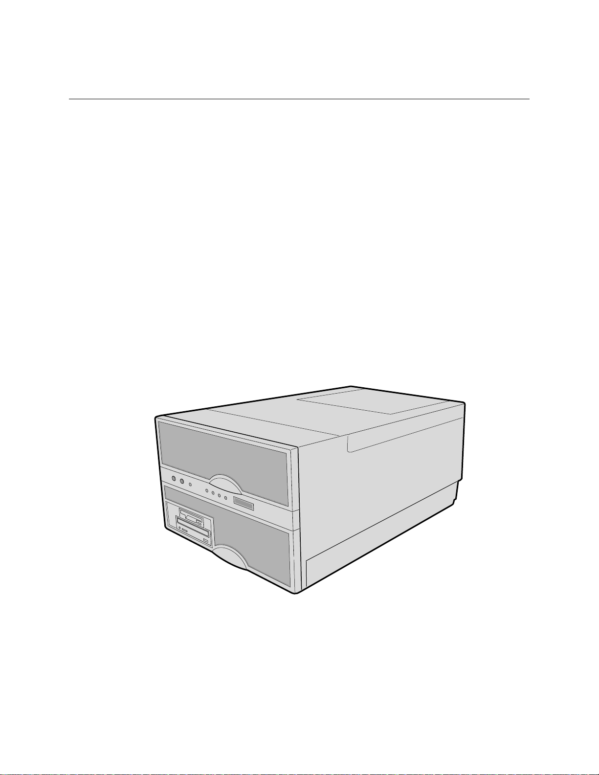
Figure 1-1. High-performance Server
OM07311
17
Page 19

AC450NX Rack Server System Product Guide
The easy-to-integrate server can easily accommodate the needs of a variety of high performance
applications—for example, network servers, multiuser systems, and large database operations. As
your application requirements increase, you can upgrade your server with:
• More powerful processors
• Additional memory
• Other peripheral devices
• Add-in I/O boards
Server Features
Feature Comment
Power system with r edundancy The 750 watt, 220 VAC autoranging power supplies include integrated
fans for cooling. In a rack server with three supplies (2 + 1), the third
one is redundant. The supplies can be replaced—hot-swapped—
without turning the server power off. The server requires a minimum of
two power supplies. LEDs on the back of the power supply indicate
power on, failure, and predictive failure.
Server chassis The electrogalvanized metal used in manufacturing the server chassis
minimizes electromagnetic interference (EMI) and radio frequency
interference (RFI).
3.5-inch diskette drive in the 3.5-inch bay.
5.25-inch IDE CD-ROM drive in the 5.25-inch half-height bay.
Two 3.5-inch wide by 1.0-inch or 1.6-inch hot-swappable LVDS hard
disk drives mounted side-by-side in the 3.5-inch hot-docking bays. The
hot-docking bays allow hot-swapping of hard disk drives without
shutting down the server.
Three power supply bays populated with either two or three power
supplies.
Ten I/O expansion slot covers.
The plastic front bezel provides airflow and easy access to drives in the
hot-docking bays. The removable top covers provide proper airflow
and easy access to components inside the server. A padlock (not
supplied) on the back of the chassis secures the covers to prevent
unauthorized entry into the server—only technically qualified personnel
should remove the server covers.
Cooling system with redundancy Six fans (5 + 1) cool and circulate air through the server. The sixth fan
is redundant. The fans can be replaced—hot-swapped—without
turning the server power off. An LED mounted next to each fan
guarantees positive identification of the failed fan.
Integrated power supply fans—two or three—cool and circulate air
through the power supplies and the bottom of the chassis.
continued
18
Page 20

Chapter 1 Introduction to the High-performance Server
Server Features (continued)
Feature Comment
Front panel board The front panel board provides the user interface to the server. The
board allows other servers to communicate with this server, even while
power is down, via an Intelligent Chassis Management Bus (ICMB).
Push-button switches control power-up, reset, and nonmaskable
interrupt (NMI) functions.
LEDs indicate power on, power supply failure, hard drive failure, or a
fan or other server cooling failure.
An LCD panel provides information about boot status, available number
of processors, and other server management information.
Server management Interintegrated circuit bus (I2C) for diagnostic and intrachassis
communication. ICMB for interchassis platform management
communications.
Real-time clock/calendar (RTC).
Front panel controls and indicators (LEDs).
Basic Input/Output System (BIOS), Power-on Self Test (POST), and
Setup Utility stored in a flash memory device.
System Setup Utility (SSU).
SCSI Configuration Utility.
Emergency Management Port (EMP) Utility.
Field Replacement Unit (FRU) and Sensor Data Record (SDR) Load
Utility.
CPU baseboard The baseboard supports up to four Pentium® II Xeon™ processors,
each processor is packaged in a Single Edge Contact (S.E.C.)
cartridge; the baseboard supports two memory modules.
Pentium II Xeon processor
packaged in an S.E.C. cartridge
Memory module Each memory module supports up to 4 GB of ECC memory using
The cartridge includes the processor core and L2 cache components.
sixteen 72-bit dual inline memory modules (DIMMs). (The CPU
baseboard requires two memory modules, one must contain DIMMS.)
continued
19
Page 21

AC450NX Rack Server System Product Guide
Server Features (continued)
Feature Comment
PHP I/O baseboard One 16-bit ISA expansion slot shares a common chassis I/O expansion
slot with a 32-bit PCI slot (you can use the shared slot for either ISA or
PCI but not both).
Six 32-bit PCI expansion slots; one of them shares a common chassis
I/O expansion slot with the ISA slot (you can use the shared slot for
either PCI or ISA but not both).
Four 64-bit PCI hot-plug expansion slots.
Integrated Cirrus Logic GD5446 VisualMedia† PCI super video graphics
array (SVGA) controller with 2 MB of video memory.
The Symbios† 53C896 LVDS SCSI controller supports two LVDS
channels. One channel controls internal devices such as CD-ROMs,
tape, and DVDs drives, in addition to the two hard drives in the
peripheral bay. The other channel provides a connection to external
devices.
The diskette controller supports one drive.
The PCI-enhanced Integrated Drive Electronics (IDE) interface
supports one IDE bus.
PS/2†-compatible keyboard/mouse controller.
Two universal serial bus (USB) ports.
I/O riser card This card contains all legacy I/O connections; it plugs into a card edge
connector on the PHP I/O baseboard.
PS/2-compatible keyboard and mouse ports (these are
interchangeable).
PS/2-compatible parallel port.
Analog VGA, 15-pin video port.
Two PS/2-compatible, 9-pin serial ports.
Midplane The midplane
• electrically connects the PHP I/O, memory, power supplies and
• distributes DC power to the PHP I/O and CPU baseboards,
• distributes the power load of the server among two or three
Front side bus (FSB) terminator
module
Peripheral bay backplane This backplane supports hot-swapping of SCA type SCSI drives,
This module plugs into any unpopulated slot 2 connector on the CPU
baseboard. This module terminates the FSB GTL+ signals of the slot 2
connector when a processor S.E.C. cartridge is not installed in it.
mounted in carriers, in and out of the hot-docking bays.
CPU baseboard
peripheral bay backplane, cooling fans, and the front panel board
750 watt autoranging power supplies
20
Page 22
Chapter 1 Introduction to the High-performance Server
Chassis
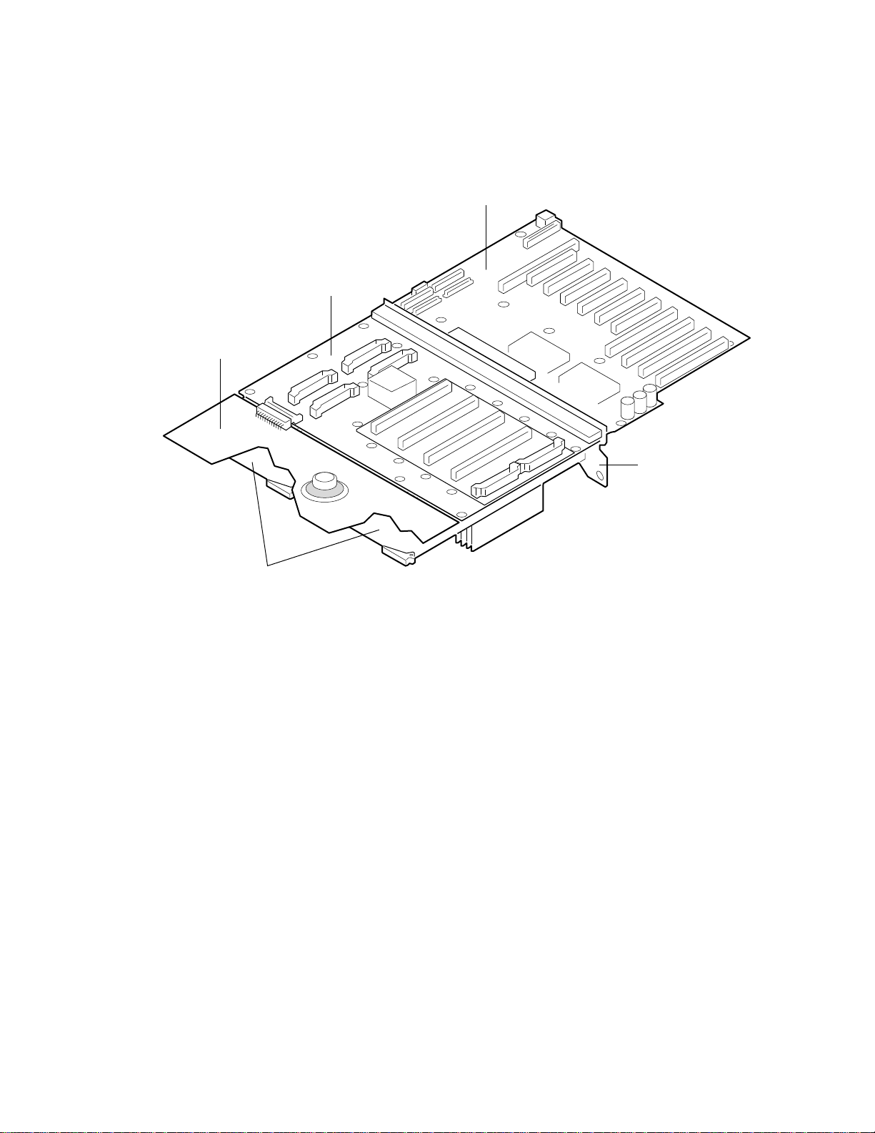
Figures 1-2 and 1-3 show the major components of the server.
B
A
C
D
E
OM07330
Figure 1-2. Chassis, Board Set
A. Front panel board
B. CPU baseboard and processors
C. PHP I/O baseboard
D. Midplane
E. Memory modules
21
Page 23
AC450NX Rack Server System Product Guide
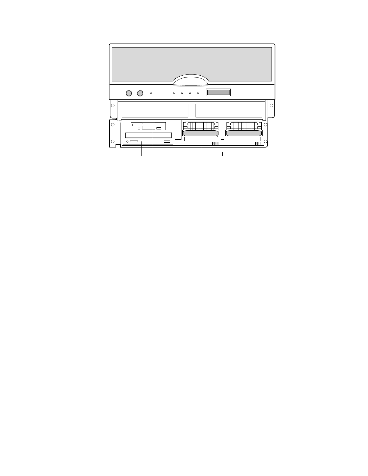
A CB
Figure 1-3. Chassis, Front View
A. 3.5-inch diskette drive (3.5-inch bay)
B. CD-ROM drive (5.25-inch bay)
C. Hot-swap bays
OM07349
22
Page 24
Chapter 1 Introduction to the High-performance Server
A CB
D
E
F
N
G
H
I
M
J
L
K
OM07300
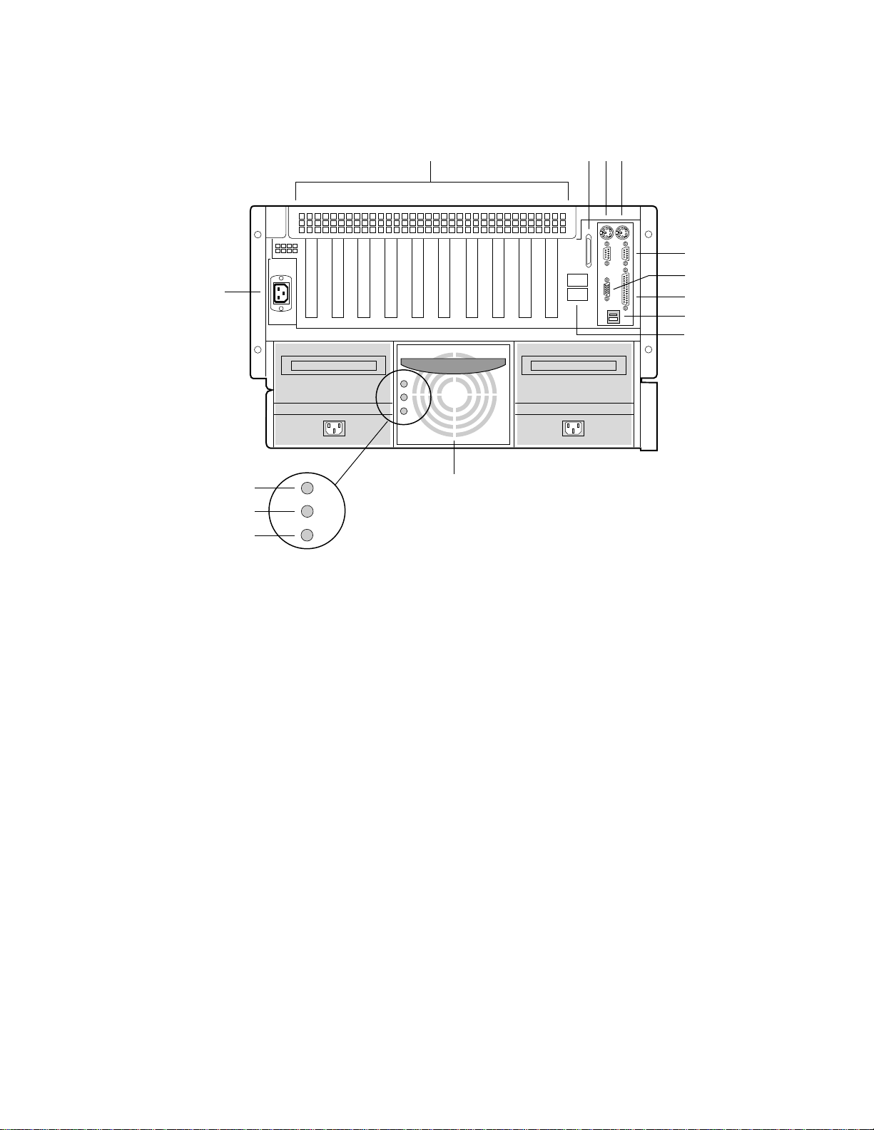
Figure 1-4. Chassis, Rear View
A. PCI and ISA add-in board expansion slots
B. External LVDS connector
C. PS/2-compatible keyboard/mouse port, 6-pin
D. PS/2-compatible keyboard/mouse port, 6-pin
E. PS/2-compatible serial ports 0 and 1, 9-pin RS-232 connector
F. Super VGA compatible, 15-pin video connector
G. PS/2-compatible parallel port (LPT), 25-pin bidirectional subminiature D connector
H. USB ports 0 and 1, 4-pin connector
I. Intelligent Chassis Management Bus (ICMB) connectors port 1 and 2
J. Power Supplies
K. Failure LED (yellow)
L. Predictive failure LED (yellow) for power supply fan
M. Power LED (green)
N. AC input power connector
23
Page 25

AC450NX Rack Server System Product Guide
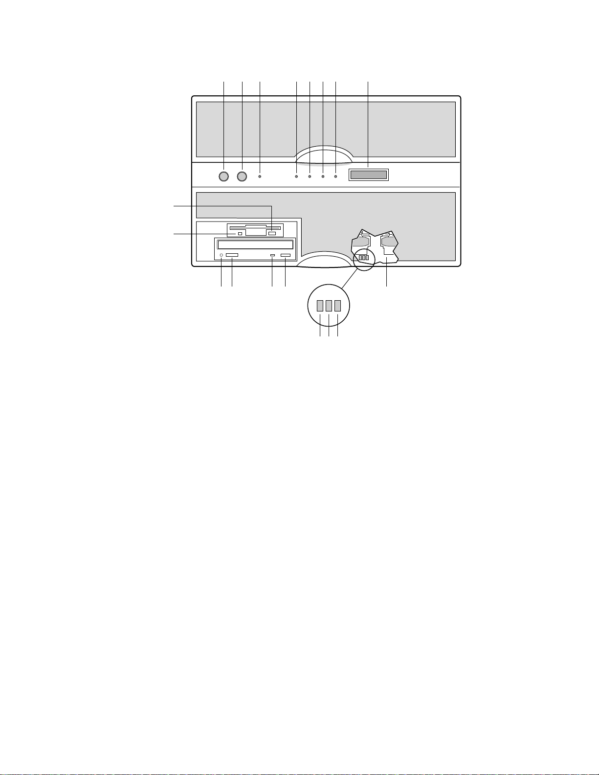
Controls and Indicators
Item Feature Description
Front Panel
A Power switch When pressed, it turns on or off the DC power inside the server.
B Reset switch When pressed, it resets the server and causes the power-on self test
(POST) to run.
C NMI switch When pressed, it causes a nonmaskable interrupt. This switch is
recessed behind the front panel to prevent inadvertent activation. It
must be pressed with a narrow non-conductive tool (not supplied).
D Power LED (green) When lit continuously, it indicates the presence of DC power in the
server. It goes out when the power is turned off or the power source
is disrupted.
E Power fault LED (yellow) When lit continuously, it indicates a power supply failure.
F Cooling fault LED (yellow) When lit, it indicates a fan failure has been detected in the server.
G Drive fault LED (yellow) When lit continuously, it indicates an asserted fault status on one or
more hard disk drives in the hot-docking bay. When flashing, it
indicates drive reset in progress.
H Front panel LCD It displays information about processor type and failure codes.
I SCSI drive hot-docking
bays
Status LEDs for SCSI Drives in Hot-docking Bays
J Drive fault LED (yellow) When lit continuously, it indicates an asserted fault status on one or
Two SCSI hot docking bays for 3.5-inch x 1.0 inch or 1.6-inch SCSI
hard drives.
more hard disk drives in the hot-docking bay. When flashing, it
indicates drive reset in progress.
K Drive activity LED (green) When flashing, it indicates drive activity.
L Drive power LED (green) When lit continuously, it indicates the presence of the drive and power
on the drive.
CD-ROM Drive
M Open/close button When pressed, it opens or closes the CD tray.
N Activity LED When lit, it indicates the drive is in use.
O Volume control It adjusts the volume of headphones or speakers.
P Headphone jack It provides a connection for headphones or speakers.
3.5-inch Floppy (Diskette) Drive
Q Activity LED When lit, it indicates the drive is in use.
R Ejector button When pressed, it ejects the diskette.
24
Page 26
Chapter 1 Introduction to the High-performance Server
HA B C D E F G
R
Q
O N IMP
L K J
Figure 1-5. Server Controls and Indicators
OM07344
25
Page 27

AC450NX Rack Server System Product Guide
Server Security
There are several ways to prevent unauthorized entry or use of the server.
Security with the Setup utility:
• Set server administrative and user passwords.
• Set secure mode to prevent keyboard or mouse input and to prevent use of the front panel
controls.
Security with the System Setup Utility (SSU):
• Enable the keyboard lockout timer so that the server requires a password to reactivate the
keyboard and mouse after a specified time-out period—1 to 128 minutes.
• Set an administrative password.
• Set a user password.
• Activate the secure mode hot-key.
• Disable writing to the diskette drive.
Password Protection
BIOS passwords prevent unauthorized tampering with the server. If you set the user password, but
not the administrative password, the BIOS requires you to enter the user password before you can
boot the server or run the SSU. If you set both passwords, entering either password lets you boot
the server or enable the keyboard and mouse. Only the administrative password lets you change
the server configuration with the flash-resident Setup utility.
Secure Boot Mode
The secure boot mode allows the server to boot and run the operating system (OS). However, you
cannot use either the keyboard or the mouse until you enter the user password.
You can use Setup to put the server in the secure boot mode. If the BIOS detects a disk in the
CD-ROM drive or a diskette in floppy drive A at boot time, it prompts you for a password. When
you enter the password, the server boots from the disk in the CD-ROM drive or the diskette in
drive A. Entering a password also disables the secure mode.
If there is no disk in the CD-ROM drive or diskette in drive A, the server boots from drive C. It
automatically goes into secure mode. All enabled secure mode features go into effect at boot time.
If you set a hot-key combination, you can secure the server immediately.
Boot Sequence Contr ol
The BIOS security features determine the boot devices and the boot sequence. They also control
disabling writes to the diskette drive in secure mode. You can use the SSU to select each boot
device. The default boot sequence is diskette, hard disk, CD-ROM, and Network.
26
Page 28

Chapter 1 Introduction to the High-performance Server
Boot Without Keyboard
The server can boot with or without a keyboard. Before it boots, the BIOS displays a message
about the keyboard stating whether or not it detects one. During POST, the BIOS automatically
detects and tests the keyboard if it is present.
Locked Power and Reset Switches
The power and reset push-button switches on the front panel are locked when the server is in the
secure mode. To exit from the secure mode, you must enter your user password.
Diskette Write Protect
If Diskette Write Protect is enabled in Setup, it write-protects the diskette drive only while the
server is in the secure mode. To exit from the secure mode, you must enter your user password.
Video Blanking
If Video Blanking is enabled in Setup, the video display will be off when the server is in the secure
mode. To exit from the secure mode, you must enter your user password.
Emergency Management Port (EMP)
The Emergency Management Port (EMP) is a feature of Server Management. EMP lets the Front
Panel Controller (FPC) communicate with a EMP console via the serial port even if the server
power is off. To enable this feature in the flash-resident Setup, an administrator must enter a
unique EMP password. If the administrator enters a new EMP password or clears an old one, the
2
BIOS sends the appropriate command via the I
wants to change the password from within Setup again, the new password must be entered twice.
If the administrator sets the Password Clear jumper to the Clear position, the BIOS clears the
administrator and user passwords. It also attempts to clear the EMP password. If the FPC is not
present or is not functioning properly, the BIOS times out and continues.
C bus interface to the FPC. If the administrator
27
Page 29

Blank page
Page 30

2 On-site Installation: Installing the Server
This chapter tells how to:
• Select a site
• Connect input and output devices
• Turn on the server and create installation diskettes from the Server System Configuration
Software CD
• Read and print a copy of this manual
• Exit to DOS
WARNING
The minimum server configuration weighs about 51.4 kg (113 lbs), and
the maximum one weighs close to 60 kg (132 lbs). To avoid personal
injury, have someone help you move the server. Do not attempt to lift
or move the server by holding the handles on the power supply.
Selecting a Site
The server operates reliably within the specified environmental limits (see page 30). The chosen
site must be close to a grounded power outlet applicable for the electrical code of that region. The
minimum available power requirements are described in Chapter 20, “Power System:
Description/Calculating Power Usage”.
CAUTION
Ensure that the power service connection is through a properly grounded
outlet.
The site must also be:
• Clean and dust-free
• Well ventilated and away from sources of heat
• Isolated from strong electromagnetic fields and electrical noise caused by electrical devices
such as air conditioners, large fans, large electric motors, radio and TV transmitters, and high
frequency security devices
• Spacious enough to provide sufficient room behind and around the server so that you can
remove AC power from it by unplugging the power cord from the AC inlet filter or wall outlet
• Away from sources of vibration or physical shock
29
Page 31

AC450NX Rack Server System Product Guide
Physical Specifications
Height 31.12 cm (12.25 inches)
Width 44.45 cm (17.5 inches)
Depth 71.12 cm (28.0 inches)
Weight 51.4 kg (113 lbs) minimum configuration; 60 kg (132 lbs) maximum configuration
Environmental Specifications
Temperature
Nonoperating
Operating
Humidity
Operating wet bulb
Nonoperating
Operating
Shock
Nonoperating
Operating
Altitude 0 to 3048 m (0 to 10000 ft) Maximum ambient temperature is linearly
Acoustic
Sound pressure
Sound power
Electrostatic discharge (ESD) Tested to 20 kilovolts (kV), no component damage. (CD-ROM drive tested
AC Input Power
100-120 V~
200-240 V~
–40° to 70 °C (–40° to 158 °F)
5° to 40 °C (41° to 104 °F); with maximum derated 1°C for every 1000 ft
(305 m) above 1524 m (5000 ft).
Not to exceed 37.6 °C (100.4 °F) without peripherals
95% noncondensing at 55 °C (131 °F)
85% noncondensing at 40 °C (104 °F)
30 g trapezoidal, 11 msec
2.0 g, 11 msec, 1/2 sine
derated between 1524 m (5000 ft) and 3048 m (10000 ft) by 1 °C per
305 m (1000 ft)
<=55dbA at ambient temperatures < 28 °C measured at bystander
positions in operating mode.
<= 6.5 BA at ambient temperatures < 28 °C in operating mode.
to 15 kV, manufacturer’s specification.)
Two ( or three) power supplies, fully loaded
100-120 V~, 6.0 A, 50/60 Hz
200-240 V~, 4.0 A, 50/60 Hz
30
Page 32

Chapter 2 On-site Installation: Installing the Server
After Unpacking the Server
Inspect the shipping box for evidence of mishandling during transit. If the shipping box is
damaged, photograph it for reference. After removing the contents, keep the damaged box and the
packing materials. If the contents appear damaged, file a damage claim with the carrier
immediately.
Save the shipping boxes and packing materials to repackage the server in the event you decide to
move it to another site.
Connecting Peripheral Devices
CAUTION
Before connecting peripheral devices to the server, verify that the power
cord is unplugged from the AC inlet filter or wall outlet. Otherwise,
equipment damage can result.
Only a qualified service technician is authorized to remove the server
covers and to access any of the components inside the server.
If your server normally operates without a video monitor and keyboard—for example, as a
network server—you must install them to configure it. You may remove them after running the
SSU. See Chapter 5, “System Setup Utility: When to Run” for information about running this
utility.
Connect your keyboard, mouse, monitor, and other peripheral devices after a qualified service
technician installs internal options. See Figure 2-1.
Keyboard and Mouse
Monitor
Other Devices
Connect the signal cable of a PS/2-compatible keyboard or mouse to either one
of the 6-pin miniature Deutsche Industrie Norm (DIN) connectors on the server
back panel. The BIOS detects and initializes the keyboard and mouse ports
accordingly. Each port is overcurrent protected by a 1-ampere positive
temperature coefficient (PTC) resistor.
Connect the signal cable of the video monitor to the 15-pin connector of the
Super VGA port on the back panel.
Connect other external peripheral devices by following the manufacturer’s
documentation. The back panel also provides two serial ports, a parallel port,
and two USB ports. The back of the chassis provides two Intelligent Chassis
Management Bus (ICMB) ports.
31
Page 33

AC450NX Rack Server System Product Guide
A
B
I
C
D
F
E
H
G
OM07335
Figure 2-1. Server I/O Connections
A. PS/2-compatible keyboard/mouse port, 6-pin connector
B. PS/2-compatible keyboard/mouse port, 6-pin connector
C. PS/2-compatible serial port 2 (COM2), 9-pin RS-232 connector
D. PS/2-compatible serial port 1 (COM1), 9-pin RS-232 connector
E. Super VGA compatible, 15-pin video connector
F. PS/2-compatible parallel port (LPT), 25-pin bidirectional subminiature D connector
G. USB ports 0 and 1, 4-pin connectors
H. External LVDS SCSI connector
I. Intelligent Chassis Management Bus (ICMB) port 1 and 2, SEMCONN
connector
†
6-pin
32
Page 34

Chapter 2 On-site Installation: Installing the Server
Obtaining a Power Cord Set
WARNING
Do not attempt to modify or use an AC power cord that is not the exact
type required.
Because a power cord is not supplied for the server, you must obtain a power cord that meets the
following criteria:
For North America the cord must be UL Listed/CSA Certified, 14/3, 75 °C type SJT with
NEMA 6-15P attachment plug and IEC 320, C19 outlet.
For outside North America the cord must be flexible VDE certified or <HAR> (harmonized)
rated 250 V, 0.75 mm
than the product ratings. The attachment plug shall be a three conductor grounding type, rated
125% of the total input current rating of the product and must be for the configuration in the
specific region or country. The attachment plug must bear at least an accepted safety agency
certification mark for the specific region or country.
The cord must be no longer than 4.5 meters (14.76 ft).
2
minimum conductor size with IEC 320, C19 outlet and rated for no less
Turning on Your Server
WARNING
The push-button on/off power switch on the front panel of the server
does not turn off the AC power. To remove AC power from the server,
you must unplug the power cord from the AC inlet filter or wall outlet.
1. Make sure all external devices, such as a video monitor, keyboard, and mouse (optional) have
been connected.
2. Remove drive protection cards (if present) from the removable media drives.
3. Turn on your video monitor.
4. Plug the female end of the power cord into the AC inlet filter receptacle on the back of the
chassis.
5. Plug the male end of the power cord into a properly grounded power outlet. See page 29 for
power outlet requirements.
6. If the server does not come on when you plug the power cord into the power outlet, press the
power switch on the front panel.
7. Verify that the power-on light on the front panel is lit. After a few seconds the power-on self
test (POST) begins. See “Power-on Self Test” on page 35.
33
Page 35

AC450NX Rack Server System Product Guide
HA B C D E F G
OM07334
Figure 2-2. Server Power and Reset Switches
A. Power switch
B. Reset switch
C. NMI switch
D. Power LED (green)
E. Power fault LED (yellow)
F. Cooling fault LED (yellow)
G. Drive fault (yellow)
H. Front panel LCD
34
Page 36

Chapter 2 On-site Installation: Installing the Server
Power-on Self Test
Each time you turn on the server the power LED on the front panel turns on and the power-on self
test (POST) starts running. POST checks the I/O system board, processor system board, keyboard,
and most installed peripheral devices.
During the memory test, POST displays the amount of memory that it is able to access and test.
Depending on the amount of memory installed on each memory board, the test may take several
minutes.
These screen prompts and messages appear after the memory test:
Mouse initialized....
Keboard detected
Press <F2> to enter SETUP
Do NOT press <F2>. The above message remains for about a second, and POST continues. The
server beeps once, and this message appears:
Operating system not found
Go to “Booting From the Server Configuration Software CD” on page 36.
35
Page 37

AC450NX Rack Server System Product Guide
Booting From the Server Configuration Software CD
CAUTION
The Server Configuration Software CD contains only a limited operating
system. This limited operating system provides enough function to let you
boot from the CD and copy and use the utility and manual files from the CD.
But this limited OS is NOT intended to be copied onto diskettes or onto your
†
hard disk as a full-function OS that supports networking or Windows
run your server and applications, you must buy the OS of your choice and
install it on the server.
See Figure 2-3.
1. Open the CD tray by pressing the open/close button on the front panel of the CD-ROM drive—
the tray will slide out of the drive.
2. Open the CD case. Press down on the center hub of the case with your finger to release the
hub tension on the CD.
. To
CAUTION
Handle the CD only by the inner and outer edges. Do not touch the data side
of the CD—the side without the label.
3. Gently grasp the center hole and outer edge of the CD, remove it from the case, and place it
label-side up in the tray.
4. Press the open/close button or gently push on the tray—it will automatically slide into the
drive.
A B
OM06774
Figure 2-3. CD-ROM Drive
A. Open/close push-button switch
B. CD tray
5. Press the reset switch on the front panel to reboot the server.
6. When POST completes, the server beeps once, boots from the CD, installs a mouse driver, and
displays the CD-ROM menu. Use the arrow keys to scroll through the menu bar and to view
the tasks in the pop-up menus.
36
Page 38

Chapter 2 On-site Installation: Installing the Server
NOTE
✏
If you do not see the CD-ROM menu but see the following message instead,
Operating system not found
you need to change the “Boot Device Priority” to the CD-ROM. See
“Server Won’t Boot From the CD” on page 38 for instructions.
Copying Configuration Software to Diskettes
When you copy software from the CD onto diskettes, device drivers suitable for several different
operating systems are copied onto the diskettes. However, your operating system will read only
those drivers it can recognize, so you cannot usually check the directory of a diskette that is not
formatted for your operating system. Instead, you may see a message to the effect, “disk not
formatted, do you want to format it now?” Don’t worry; the drivers for YOUR operating system
should be present on the diskette and available for you to load on the system.
1. Before starting, make sure that you have on hand several blank high-density diskettes.
2. From the CD-ROM menu bar, select Create Diskettes and press <Enter>.
3. Follow the prompts to copy the software onto the diskettes.
4. When finished, select Quit to DOS (on the CD-ROM menu bar), and press <Enter>.
5. Remove the CD from the drive.
Installing Video Drivers
After configuring the server, you can install various video drivers to take full advantage of the
enhanced features provided by the onboard Cirrus Logic GD5446 PCI VisualMedia accelerator.
The server may not operate properly without these drivers installed.
After copying the drivers from the Configuration Software CD to diskettes, read the
README.TXT file on the Display Drivers and DOS Utilities diskette. The .TXT file contains the
most current information about which video drivers you need to install on your server. Follow the
installation instructions in the README.TXT file.
Follow these steps to install these drivers::
1. Fully configure your server. (This can include adding application software, an ISA add-in
board, PCI add-in boards, and the like.)
†
2. Insert disk 1 of the video drivers and utilities for MS-DOS
3. At the DOS command prompt, type
4. Follow the onscreen directions to install the video drivers.
A:install and press <Enter>.
and Windows into drive A.
Installing SCSI Drivers
After copying the SCSI drivers from the Configuration Software CD to diskettes, follow the
instructions in the README.TXT file on the first diskette to install the drivers.
37
Page 39

AC450NX Rack Server System Product Guide
Server Won’t Boot From the CD
It is possible that your server was shipped with the diskette drive or another device set as the first
boot device. If so, the server will try to boot from a diskette or other device rather than from the
CD we have provided. By pressing <Esc> during POST, you can override the boot sequence
specified in Setup by selecting a different primary boot device. This override is valid only for that
specific boot. Subsequent boots revert back to the sequence specified in Setup. If the chosen
device fails to load the operating system, the BIOS reverts to the previous boot sequence. The
<Esc> hot key is valid while the “Press <F2> key to enter Setup” message is displayed on the
screen. At the end of POST, if the <Esc> key was pressed, a pop-up boot menu is displayed. It
allows you to change the boot sequence, or to enter Setup and permanently change the sequence.
Follow these steps to install these drivers:
1. Press the reset switch on the front panel to reboot the server—the CD can be in the drive or
not.
2. When POST displays this message:
Press <F2> to enter SETUP
3. Press <Esc> and wait for the following boot menu to display:
Figure 2-4. Boot Menu
4. From the boot menu, select the CD-ROM drive, and press <Enter>.
5. When you see the following pop-up menu, press <Enter> to boot from the CD.
Figure 2-5. CD-ROM Boot Menu
38
OM08360
OM08361
Page 40

Chapter 2 On-site Installation: Installing the Server
The server should now boot from the CD, displaying a menu bar that includes creating diskettes,
diagnostics, reading/printing the manual, and quitting to DOS.
CAUTION
If the server does not operate as described in this chapter, contact a qualified
service technician.
39
Page 41

This page should be blank
Page 42

3 Power-on Self Test: Description/Running
Power-on Self Test (POST)
WARNING
The push-button on/off power switch on the front panel of the server
does not turn off the AC power. To remove AC power from the server,
you must unplug the power cord from the AC inlet filter or wall outlet.
Each time you turn on the server the power LED on the front panel turns on and POST starts
running. It checks the PHP I/O baseboard, CPU baseboard, keyboard, and most installed
peripheral devices. During the memory test, POST displays the amount of memory that it is able
to access and test. Depending on the amount of memory installed on the memory module, it may
take several minutes to complete the memory test.
Turn on your video monitor and server. After a few seconds the power-on self test (POST) begins.
You can enter Setup when POST displays this message:
Press <F2> to enter SETUP
If you press <F2>, follow the instructions on the monitor when Setup appears.
NOTE
✏
Because POST must complete test and initialization functions after pressing
<F2>, a few seconds may pass before entering Setup.
If you do not press <F2>, POST continues.
During boot, the server recognizes and displays the BIOS banner for the onboard Sl53C896 SCSI
host adapter on the PHP I/O baseboard.
When the BIOS banner for the SCSI host adapter appears, you can run the included SCSI
configuration utility by pressing <Ctrl+C> when this message appears:
Press <Ctrl><C> To Enter Configuration Utility!
If you have installed SCSI devices in the server, press <Ctrl+C>. When the utility appears, follow
the instructions on the monitor to configure the host adapter. See Chapter 6, “SCSI Configuration
Utility,” for instructions.
41
Page 43

AC450NX Rack Server System Product Guide
If POST detects an error, it displays the error code, the server beeps once, and this message
appears:
Press <F1> to Resume, <F2> for Setup
To resume, press <F1>. However, if a drive with bootable media is not detected, the server beeps
once, and this message appears:
Operating System not found
To enter Setup, Press <F2>. When the Setup utility appears, follow the instructions on the
monitor.
If POST did not detect an error and you choose not to run the SCSI Configuration Utility, POST
continues, the server beeps once, and this message appears:
Operating System not found
See Chapter 2, “On-site Installation: Installing the Server,” for instructions on creating software
installation diskettes.
If the server halts before POST completes running, it emits a beep code indicating a fatal system
error that requires immediate attention. If POST can display a message on the video monitor, it
causes the speaker to beep twice as the message appears.
Note the screen display and write down the beep code you hear; this information is useful for your
service representative. For a listing of beep codes and error messages that POST can generate, see
Chapter 22, "Solving Problems: Troubleshooting/Error Messages."
42
Page 44

4 Setup Utility: When to Run
The flash-resident BIOS Setup utility is used to configure PHP I/O baseboard resources. It is
stored in both flash memory (NVRAM) and the battery-backed memory of the real-time clock
(RTC) on the PHP I/O baseboard.
When to Run the BIOS Setup Utility
The BIOS Setup is a flash-based configuration utility that is used to configure onboard resources
and to set user-selectable options such as boot device ordering, keyboard autorepeat, and security.
Use Setup to configure the server into a bootable state, and then use the SSU and other utilities to
further configure the server.
Setup lets you change the server configuration defaults. It does not allow you to enter or change
information about PCI or ISA add-in boards; you must use the SSU instead. Setup stores the
configuration values in flash memory; they take effect when you boot the server. POST checks
these values against the actual hardware configuration; if they do not agree, POST generates an
error message. You must then run Setup to specify the correct configuration.
You can run Setup with or without an operating system being present.
Because values entered using Setup are overwritten when you run the SSU, you should run Setup
only under the following conditions:
• If the diskette drive is disabled.
• If the server has a diskette drive that is disabled or improperly configured, use Setup to
configure the server into a bootable state, and then use the SSU and other utilities to further
configure the server. In Setup, you can enable the drive so you can use the SSU. If necessary,
you can disable the diskette drive again after exiting the SSU.
• If the server does not have a diskette drive, or it is disabled, use Setup to configure the server.
• If you have installed only an ISA add-in board in your server.
If the server has a properly configured, enabled diskette drive, use the SSU to configure the server.
Information entered using the SSU overrides any entered using Setup.
Running the Setup Utility
You can enter Setup under several conditions:
• when you turn on the server
• when you reboot the server by pressing the push-button reset switch on the front panel
• when you reboot the server by pressing <Ctrl+Alt+Del> while at the DOS operating system
prompt
• when you turn on or reset your server after an orderly shutdown of an operating system other
than DOS
43
Page 45

AC450NX Rack Server System Product Guide
Each time you turn on or reboot your server POST begins and, after a few seconds, displays this
message:
Press <F2> to enter Setup
After pressing F2, a few seconds may pass before entering Setup while POST completes tests and
initialization functions. When the F2 prompt disappears, pressing F2 will have no effect. When
Setup is entered, the Main Menu options page is displayed.
Use the following keys to navigate through the menus and submenus.
Press To
F1 Get help about an item
ESC Go back to a previous item
↑ Select the previous value in a menu option list
↓ Select the next value in a menu option list
← → Select a major menu
- Change the value of the current menu item to the previous value
+ Change the value of the current menu item to the next value
Enter Activate submenus, select feature options, and change feature values
F9 Display the following message:
Setup Confirmation
The [Yes] button will be highlighted. If you press <Enter>, all Setup fields return to their
default values. If you press <ESC> or select No, the server returns to the configuration it had
before you pressed <F9>, without affecting any existing field values.
F10 Display the following message:
Save configuration changes and exit now?
The [Yes] button will be highlighted. If you press <Enter>, all current Setup values are saved,
and the system is reset. If you press < ESC> or select No, the server returns to the
configuration it had before you pressed <F10>, without affecting any existing values.
Load default configuration now?
[Yes] [No]
Setup Confirmation
[Yes] [No]
44
Page 46

Main Menu
Default values are in bold typeface, and auto-configured values are shaded.
Feature Option Description
System Time HH:MM:SS Set the System Time. To select a field, press <Tab>,
<Shift + Tab>, or <Enter>. Then type in a new value. If
you replace the battery, the default time is 00:00. (This is
a 24-hour clock.)
System Date MM/DD/YYYY Set the System Date. To select a field, press <Tab>,
<Shift + Tab>, or <Enter>. Then type in a new value. If
you replace the battery, the default date is Jan 1990.
Legacy Diskette A: Disabled
360 KB, 5 ¼”
1.2 MB, 5 ¼”
720 KB, 3 ½”
1.44/1.25 MB, 3 ½”
2.88 MB, 3 ½”
Legacy Diskette B:
Primary Master CD-ROM Press <Enter> for options.
Autotype Fixed Disk: Press <Enter> Pressing <Enter> attempts to detect the drive type for
Type: User
Multi-sector Transfers: Disabled
LBA Mode Control Disabled
32-bit I/O:
Transfer Mode Standard
Ultra DMA Mode: Disabled
Primary Slave None Press <Enter> for options.
Autotype Fixed Disk: Press <Enter> Pressing <Enter> attempts to detect the drive type for
Disabled
360 KB, 5 ¼”
1.2 MB, 5 ¼”
720 KB, 3 ½”
1.44/1.25 MB, 3 ½”
2.88 MB, 3 ½”
Auto
1-39
CD-ROM
ATAPI Removable
Disabled
Enabled
Select the diskette type for drive A:. (The 1.25 MB,
3.5-inch refers to a 1024 byte/sector Japanese media
format. To support the 1.25 MB, 3.5-inch requires a
3.5-inch 3-mode diskette drive.)
Select the diskette type for drive B: (The size 1.25 MB,
3.5-inch refers to a 1024 byte/sector Japanese media
format. To support the 1.25 MB, 3.5-inch requires a
3.5-inch 3-mode diskette drive.)
drives that comply with ANSI specifications.
User—lets you enter the parameters of the hard disk
drive installed at this connection.
Auto—autotypes the hard disk drive installed here.
1-39—lets you select the predetermined hard disk drive
installed here.
CD-ROM—a CD-ROM is installed here.
ATAPI Removable—removable disk drive installed here.
Enabled allows 32-bit IDE data transfers.
drives that comply with ANSI specifications.
Chapter 4 Setup Utility: When to Run
continued
45
Page 47

AC450NX Rack Server System Product Guide
Main Menu (continued)
Feature Option Description
Type: User
Auto
1-39
CD-ROM
ATAPI Removable
32-bit I/O:
Ultra DMA Mode: Disabled
Secondary Master None Press <Enter> for options.
Autotype Fixed Disk: Press <Enter> Pressing <Enter> attempts to detect the drive type for
Type: User
32-bit I/O:
Ultra DMA Mode: Disabled
Secondary Slave None Press <Enter> for options.
Disabled
Enabled
Auto
1-39
CD-ROM
ATAPI Removable
Disabled
Enabled
User—lets you enter the parameters of the hard disk
drive installed at this connection.
Auto—autotypes the hard disk drive installed here.
1-39—lets you select the predetermined hard disk drive
installed here.
CD-ROM—a CD-ROM is installed here.
ATAPI Removable—removable disk drive installed here.
Enabled allows 32-bit IDE data transfers.
drives that comply with ANSI specifications.
User—lets you enter the parameters of the hard disk
drive installed at this connection.
Auto—autotypes the hard disk drive installed here.
1-39—lets you select the predetermined hard disk drive
installed here.
CD-ROM—a CD-ROM is installed here.
ATAPI Removable—removable disk drive installed here.
Enabled allows 32-bit IDE data transfers.
Autotype Fixed Disk: Press <Enter> Pressing <Enter> attempts to detect the drive type for
drives that comply with ANSI specifications.
Type: User
Auto
1-39
CD-ROM
ATAPI Removable
32-bit I/O:
Ultra DMA Mode: Disabled
Processor Information Press <Enter> Displays information about all processors. You cannot
Processor 1 Stepping ID 2.
Processor 1 L2 cache size [512 KB].
Processor 2 Stepping ID, absent or disabled.
Disabled
Enabled
User—lets you enter the parameters of the hard disk
drive installed at this connection.
Auto—autotypes the hard disk drive installed here.
1-39—lets you select the predetermined hard disk drive
installed here.
CD-ROM—a CD-ROM is installed here.
ATAPI Removable—removable disk drive installed here.
Enabled allows 32-bit IDE data transfers.
modify any items in this menu. Consult your system
administrator if an item requires changing.
continued
46
Page 48

Chapter 4 Setup Utility: When to Run
Main Menu (continued)
Feature Option Description
Processor 3 Stepping ID, absent or disabled.
Processor 4 Stepping ID, absent or disabled.
Keyboard Features Press <Enter> for options.
Numlock:
Key Click:
Keyboard auto-repeat
rate:
Keyboard auto-repeat
delay:
Auto
On
Off
Disabled
Enabled
30/sec
26.7/sec
21.8/sec
18.5/sec
13.3/sec
10/sec
6/sec
2/sec
1/4 sec
1/2 sec
3/4 sec
1 sec
Select power-on state for numlock.
Enabled produces the key click.
Select key repeat rate.
Select delay before key repeat.
Language
Advanced Menu
Setting items on this menu to incorrect values may cause your system to malfunction.
Feature Option Description
Plug & Play O/S:
Reset Configuration
Data:
Enable ACPI
Use Multipro cessor
Specification
Large Disk Access
Mode
English (US)
Français
Deutsch
Italiano
Español
No
Yes
No
Yes
No
Yes
1.1
1.4
CHS
LBA
Select the display language for the BIOS.
Setup Warning
Select Yes if you are using a Plug and Play capable
operating system.
Select No if you need the BIOS to configure nonboot
devices.
Select Yes if you want to clear the system configuration
data.
Select Yes if you want to enable the advanced
configuration and power interface (ACPI) BIOS.
Configure the Multiprocessor Specification revision level.
Some OSs require 1.1 for compatibility.
Select the drive access method for IDE drives. Most OSs
use logical block addressing (LBA). However, some
operating systems may use the cylinder head sector
(CHS). See your OS documentation for further help.
continued
47
Page 49

AC450NX Rack Server System Product Guide
Advanced Menu (continued)
Feature Option Description
Pause Before Boot
PCI Configurations Additional Setup menus to configure PCI devices.
PCI Device,
Embedded SCSI A
Option ROM Scan:
Enable Master:
Latency Timer: Default
PCI Devices
Option ROM Scan:
Enable Master:
Latency Timer: Default
I/O Device
Configuration
Serial Port A Disabled
Base I/O Address
Interrupt IRQ3
Disabled
Enabled
Enabled
Disabled
Enabled
Disabled
0020h
0040h
0060h
0080h
00A0h
00C0h
00E0h
Enabled
Disabled
Enabled
Disabled
0020h
0040h
0060h
0080h
00A0h
00C0h
00E0h
Enabled
Auto
3F8
2F8
3E8
2E8
IRQ4
Pause five seconds before booting the OS.
Setup items for configuring the specific PCI device.
Initialize device expansion ROM.
Enable selected device as a PCI bus master.
Allot minimum guaranteed time slice for bus master in
units of PC I bus clocks.
Initialize device expansion ROM.
Enable selected device as a PCI bus master.
Allot minimum guaranteed time slice for bus master in
units of PC I bus clocks.
Configure serial port A using these options:
• Disabled—no configuration.
• Enabled—user configuration.
• Auto—BIOS or OS chooses the configuration.
• OS Controlled—displayed when controlled by
the OS.
Set the base I/O address for serial port A.
Set the interrupt for serial port A.
continued
48
Page 50

Advanced Menu (continued)
Feature Option Description
Serial Port B Disabled
Enabled
Auto
Base I/O Address 3F8
2F8
3E8
2E8
Interrupt
Parallel Port Disabled
Mode Output only
Interrupt IRQ5
Diskette Controller Disabled
Base I/O Address
Advanced Chip Set
Control
Address Bit Permuting Disabled
Card to Card
Interleave
IRQ3
IRQ4
Enabled
Auto
Bidirectional
EPP
ECP
IRQ7
Enabled
Auto
Primary
Secondary
Enabled
Disabled
Enabled
Configure serial port B using these options:
• Disabled—no configuration.
• Enabled—user configuration.
• Auto—BIOS or OS chooses the configuration.
• OS Controlled—displayed when controlled by
the OS.
Set the base I/O address for serial port B.
Set the interrupt for serial port B.
Configure the parallel port using these options:
• Disabled—no configuration.
• Enabled—user configuration.
• Auto—BIOS or OS chooses the configuration.
• OS Controlled—displayed when controlled by
the OS.
Set the mode for the parallel port.
Set the interrupt for the parallel port.
Configure the diskette controller using these options:
• Disabled—no configuration.
• Enabled—user configuration.
• Auto—BIOS or OS chooses the configuration.
• OS Controlled—displayed when controlled by
the OS.
Set the base I/O address for the diskette controller.
Enabled automatically sets two-way or four-way
permuting based on the memory configuration. Enabled
requires:
• number of rows to be a power of two.
• all rows to be the same size.
• all populated rows to be adjacent and start at row 0.
Enabled requires a symmetric RAM configuration
between two memory modules.
Chapter 4 Setup Utility: When to Run
continued
49
Page 51

AC450NX Rack Server System Product Guide
Advanced Menu (continued)
Feature Option Description
Base RAM Step
1 MB
1 KB
Every location
Tests base memory once per MB or once per KB or
every location.
Extended RAM Step
L2 Cache Disabled
ISA Expansion
Aliasing
Memory Scrubbing Disabled
Restreaming Buffer Disabled
Read Prefetch for
PXB0A
Read Prefetch for
PXB0B
1 MB
1 KB
Every location
Enabled
Disabled
Enabled
Enabled
Enabled
16
32
64
16
32
64
Tests extended memory once per MB or once per KB or
every location.
Enabled causes the secondary cache to be sized and
enabled. Disabled causes the L2 cache to be disabled
for core clock frequency bus ratios equal to 2.
Enabled causes every I/O access with an address in the
range of x100h-x3FFh, x500h-x7FFh, x900h-xBFFh, and
xD00h-xFFFh to be internally aliased to the range 0100h03FFh before performing any other address range
checking.
Enabled lets the BIOS automatically detect and correct
single-bit memory errors.
When enabled, the data returned and buffered for a
delayed inbound read may be reaccessed following a
disconnect.
Configures the number of “Dwords” that will be
prefetched on memory read multiple commands.
Configures the number of “Dwords” that will be
prefetched on memory read multiple commands.
Read Prefetch for
PXB1A
Multiboot Support
Special VGA Devnode
16
32
64
Disabled
Enabled
Disabled
Enabled
Configures the number of “Dwords” that will be
prefetched on memory read multiple commands.
Only enable when the total number of bootable devices is
less than eight.
Enable this node only when nonPCI compliant VGA
cards need to be debugged. Enabling will impact I/O
resources for a large configuration.
50
Page 52

Security Menu
Feature Option Description
User Password Is Clear When you enter your user password, this field
Administrator
Password Is
Set User Password
Set Administrator
Password
Password on Boot
Diskette Access User
Secure Mode Timer
Secure Mode Hot Key
Secure Mode Boot
Video Blanking
Diskette Write Protect
Front Panel Lockout
Chapter 4 Setup Utility: When to Run
automatically changes to set.
Clear When you enter your administrator password, this field
automatically changes to set.
Enter
Enter
Disabled
Enabled
Administrator
Disabled
1 min
2 min
5 min
10 min
20 min
1 hr
2 hr
[ ]
Disabled
Enabled
Disabled
Enabled
Disabled
Enabled
Disabled
Enabled
The user password controls access to the system at boot.
To enter a password, press <Enter> and follow the
screen prompts.
The administrator password controls access to the setup
utility. To enter a password, press <Enter> and follow
the screen prompts.
Requires password entry before boot. The system
remains in the secure mode until you enter the password.
Password on Boot takes precedence over Secure Mode
Boot.
Controls access to diskette drives.
Select the time-out period of keyboard or mouse inactivity
required before the secure mode activates. (A password
must be entered for the secure mode to work.)
Select a hot key, and then press <Ctrl+Alt+(your hot
key)> to place the system i n the secure m ode. The key
should not conflict with any application. Available
choices are A-Z and 0-9. Press <Del> to remove the
hot key.
Enabled lets the system boots in the secure mode.
Requires a password to unlock the system.
Enabled blanks video when the secure mode activates.
Requires a password to unlock the system.
Enabled write protects the diskette drive when the
Secure Mode activates. Requires a password to restore
the diskette writes.
Enabled disables the front panel controls when the
Secure Mode activates. Requires a password to unlock
the system.
51
Page 53

AC450NX Rack Server System Product Guide
Server Menu
Feature Option Description
System Management An additional setup menu for changing server
Firmware SMIs Disabled
Enabled
System Event Logging Disabled
Enabled
Clear Event Log
Assert NMI on AERR
Assert NMI on BERR
Assert NMI on PERR
Assert NMI on SERR
Enable Host Bus Error
Server Management
Information
Board Part Number Information only.
Board Serial Number Information only.
System Part Number Information only.
System Serial Number Information only.
Chassis Part Number Information only.
Chassis Serial
Number
BMC Revision Information only.
FPC Revision Information only.
Primary HSBP
Revision
Secondary HSBP
Revision
Console Redirection Additional setup menus to configure the console.
COM Port Address
IRQ # None
Disabled
Enabled
Disabled
Enabled
Disabled
Enabled
Disabled
Enabled
Disabled
Enabled
Disabled
Enabled
Disabled
3F8
2F8
3E8
management features.
Disabled turns off all firmware SMI sources.
Enabled logs critical system events.
Enabled cleans the system event log.
Enabled generates an NMI. Enabling the Firmware SMIs
option is required to assert an NMI.
Enabled generates an NMI. Enabling the Firmware SMIs
option is required to assert an NMI.
Enabled generates an NMI. Enabling the SERR option is
required to activate this option.
Enabled generates an NMI.
Enables host single- and multi-bit errors.
Displays system ser ial number, part number , and server
management controller revisions. All items on this menu
cannot be modified in user mode. If any items require
changes, please consult your system administrator.
Information only.
Information only.
Information only.
Select the port address. Make sure these values are
identical to those of serial ports A and B in the peripheral
configuration setup menu.
continued
52
Page 54

Chapter 4 Setup Utility: When to Run
Server Menu (continued)
Feature Option Description
Baud Rate 9600
19.2 K
38.4 K
115.2 K
Flow Control No Flow Control
CTS/RTS
XON/XOFF
CTS/RTS + CD
Processor Rete st
EMP Password Switch
EMP ESC Sequence The front panel controller firmware updates this field.
EMP Hangup Line
String
Modem Init String This string accepts up to 16 characters. The upper four
EMP Access Mode Preboot Only
EMP Restricted Mode
Access
EMP Direct
Connect/Modem
Mode
No
Yes
Disabled
Enabled
Always Active
Disabled
Disabled
Enabled
Direct Connect
Modem Mode
Select the baud rate.
Select the flow control.
• CTS/RTS = Hardware
• XON/XOFF = Software
• CTS/RTS + CD = Hardware + carrier detect for
modem use.
Yes causes the BIOS to clear historical processor status
and retest all processors on the next boot.
Enable or disable the EMP password.
The front panel controller firmware updates this field.
characters will go to the next field which will pop up as
soon as the 16th character is filled. Trying to fill the 17th
character in the same field will have a wraparound
problem.
Preboot Only—EMP enabled during power down or
POST.
Always Active—EMP always enabled.
Disabled—EMP disabled.
When enabled, power down, front panel NMI, and reset
control via EMP are disabled. Restricted mode can be
selected with preboot or always active.
You can connect directly to the port or use a modem.
53
Page 55

AC450NX Rack Server System Product Guide
Boot Menu
Feature Option Description
Diskette Check:
Boot Device Priority Select the search order for the types of boot devices.
Hard Drive The system attempts to boot to the OS from the first hard
Removable Devices The OS assigns drive letters to these devices in the order
Maximum Number of
I20 Drives
Message Timeout
Multiplier
Pause During Post
Disabled
Enabled
1. Diskette Drive
2. Removable
Devices
3. Hard Drive
4. ATAPI CD-ROM
Drive
1
4
1
2
4
8
10
50
100
1000
Disabled
Enabled
Enabled verifies the diskette type on boot. Disabled
speeds up the boot process.
Use the up and down arrow keys to select a device.
Press <+> to move it up the list, and press <-> to move it
down the list. Press <Esc> to exit this menu.
drive in this list. If it does not find an OS, the system tries
the next drive listed until if finds an OS. Use the up and
down arrow keys to select a device. Press <+> to move
it up the list, and press <-> to move it down the list.
Press <Esc> to exit this menu.
displayed. Change the sequence and the drive lettering
of a device by selecting it with the up and down arrow
keys. Press <+> to move it up the list, and press <-> to
move it down the list. Press <Esc> to exit this menu.
Selects the maximum number of I20 drives that will be
assigned a DOS drive letter.
All timeout values will be multiplied by this number.
Select enabled when you need to start the IRTOS
manually. When you hear three beeps, POST has
stopped. Press any key to continue.
54
Page 56

Chapter 4 Setup Utility: When to Run
Exit Menu Selections
The following menu options are available on the Server menu. Select an option by using the up or
down arrow keys. Then press <Enter> to execute the option, and follow the prompts.
Option Description
Exit Saving Changes Exit Setup and save your changes to CMOS.
Exit Discarding Changes Exit Setup without saving data to CMOS.
Load Setup Defaults Load default values for all Setup items.
Load Custom Defaults Load settings from custom defaults.
Save Custom Defaults Save changes to custom defaults. Normally PhoenixBios reads setup
settings from CMOS. However, if CMOS fails, it uses custom defaults—if you
have set them. If not, it uses factory defaults.
Discard Changes Load previous values from CMOS for all Setup items.
Save Changes Save Setup data to CMOS.
55
Page 57

This page is blank
Page 58

5 System Setup Utility: When to Run
The System Setup Utility (SSU) is on the Server System Configuration Software CD shipped with
the server. The SSU provides a graphical user interface (GUI) over an extensible framework for
server configuration. For the AC450NX systems, the SSU framework supports the following
functions and capabilities:
• assigns resources to baseboard devices and add-in cards prior to loading the operating
system (OS)
• allows you to specify boot device order and system security options
• permits viewing and clearing of the system’s critical event log
• Permits viewing of the system FRU and SDRs
• allows troubleshooting of the server when the OS is not operational
• provides a system level view of the server’s I/O devices
When to Run the System Setup Utility
The SSU is a DOS-based utility that supports extended system configuration operations for
onboard resources and add-in boards. The utility also allows you to view the system event log
(SEL) and to set system boot and security options. Use the SSU when you need to:
• add and remove boards affecting the assignment of resources (ports, memory, IRQs, DMA)
• modify the server’s boot device order or security settings
• change the server configuration settings
• save and restore the server configuration
• view or clear the SEL
• view FRU information
• view the SDR table
If you install or remove an ISA add-in board, you must run the SSU to reconfigure the server.
Running the SSU is optional for a PCI and ISA Plug and Play add-in boards.
The SSU is PCI-aware, and it complies with the ISA Plug and Play specifications. The SSU works
with any compliant configuration (.CFG) file supplied by the peripheral device manufacturer.
The I/O baseboard comes with a .CFG file. The .CFG file describes the characteristics of the
board and the system resources that it requires. The configuration registers on PCI and ISA Plug
and Play add-in boards contain the same type of information that is in a .CFG file. Some ISA
boards also come with a .CFG file.
57
Page 59

AC450NX Rack Server System Product Guide
The SSU uses the information provided by .CFG files, configuration registers, flash memory, and
the information that you enter, to specify a system configuration. The SSU writes the
configuration information to flash memory.
The SSU stores configuration values in flash memory. These values take effect when you boot the
server. POST checks the values against the actual hardware configuration; if they do not agree,
POST generates an error message. You must then run the SSU to specify the correct configuration
before the server boots.
The SSU always includes a checksum with the configuration data so that the BIOS can detect any
potential data corruption before the actual hardware configuration takes place.
What You Need to Do
The SSU may be run directly from the Server Configuration Software CD or from a set of DOS
diskettes. If you choose to run the SSU from a set diskettes, you must copy the SSU from the
Server Configuration Software CD to diskettes and follow the instructions in the README.TXT
of diskette one. See Chapter 2, “On-site Installation: Installing the Server,” to create a set of SSU
diskettes. Only diskette one of the set must be DOS bootable.
NOTE
✏
If your diskette drive is disabled, or improperly configured, you must use the
flash-resident Setup utility to enable it so that you can use the SSU. If
necessary, you can disable the drive after you exit the SSU. Information
entered using the SSU overrides any entered using Setup.
Running the SSU
• Running the SSU Locally
Running the ssu.bat file provided on the SSU media starts the SSU. If the server boots directly
from the SSU media, the ssu.bat file runs automatically. If it boots from a different media, the
SSU can be started manually or by another application. When the SSU starts in the local
execution mode (the default mode), the SSU accepts input from the keyboard and/or mouse.
The SSU presents a VGA-based Graphical User Interface (GUI) on the primary monitor.
The SSU runs from writable, nonwritable, removable, and nonremovable media. If you run the
SSU from nonwritable media, all your preference settings will be lost because you cannot save
them.
The SSU supports the ROM-DOS V6.22 operating system. It can run on other ROM-DOS
compatible operating systems but they are not supported. The SSU will not operate from a
DOS-box running under an operating system such as Windows.
58
Page 60

Chapter 5 System System Setup Utility: When to Run
• Running the SSU Remotely
To run the SSU remotely, you must invoke the SSU.BAT file with the /t switch and redirect
the text-mode output via BIOS console redirection. The /t switch puts the display in text mode
and allows the console to be viewed and controlled via BIOS console redirection.
First, configure the server for BIOS console redirection. Then configure the modem to
auto-answer and to “modem reaction to DTR set to return to command state.” After
configuring the server, it should be booted to a DOS prompt either locally or remotely through
the EMP. Once the server boots, the remote user can use any ANSI terminal emulation
program to connect to the configured COM port and invoke SSU /t. This process requires a
bootable DOS partition, and all files required for the SSU to run must be on the server.
Starting the SSU
The SSU consists of a collection of task-oriented modules plugged into a common framework
called the Application Framework (AF). The AF provides a launching point for individual tasks
and a location for setting customization information.
1. Turn on your video monitor and your system.
2. There are two ways to start the SSU.
a. From a set of SSU diskettes created from the CD: Insert SSU diskette 1 in drive A, and
press the push-button reset switch or <Ctrl+Alt+Del> to reboot your server from the
diskette. Follow the screen prompts.
b. From the Server Configuration Software CD: Insert the CD into your CD-ROM drive,
and press the reset switch on the front panel or <Ctrl+Alt+Del> to reboot the server.
• When prompted, press <F2> to enter BIOS Setup.
• From the Boot Menu, select the Boot Device Priority option, and then select the
CD-ROM drive as your primary boot device.
• Press <F10> to save the new settings.
• Press <Enter> to exit BIOS Setup and boot from the CD.
• From the CD menu, select Run Utilities and press <Enter>.
• Select Run System Setup Utility, and press <Enter>. Follow the screen prompts.
If you boot from the CD, skip to step 4.
3. The mouse driver loads if it is available; press <Enter> to continue.
4. When the main window of the SSU appears, you can customize the user interface before
continuing.
59
Page 61

AC450NX Rack Server System Product Guide
Customizing the SSU
The SSU lets you customize the user interface according to your preferences. The AF sets these
preferences and saves them in the AF.INI file so that they take effect the next time you start the
SSU. There are four user-customizable settings.
NOTE
✏
If you run the SSU from nonwritable media like a CD, these preferences will
be lost when you exit the SSU.
• Color—this button lets you change the default colors associated with different items on the
screen with predefined color combinations. The color changes are instantaneous.
• Mode—this button lets you set the desired expertise level.
novice
intermediate
expert
The expertise level determines which tasks are visible in the Available Tasks section and what
actions each task performs. For a new mode setting to take effect, the user must exit the SSU
and restart it.
• Language—this button lets you change the strings in the SSU to strings of the appropriate
language. For a new language setting to take effect, you must exit the SSU and restart it.
• Other—this button lets you change other miscellaneous options in the SSU. The changes are
instantaneous.
To change the interface default values:
Use the mouse to click on the proper button in the Preferences section of the SSU Main
window.
or
Use the tab and arrow keys to highlight the desired button, and press the spacebar or <Enter>.
or
Access the menu bar with the mouse or hot keys (Alt + underlined letter).
Launching a Task
It is possible to have many tasks open at the same time, although some tasks may require complete
control to avoid possible conflicts. The tasks achieve complete control by keeping the task as the
center of operation until you close the task window.
To launch a task:
1. In the SSU Main window, double-click on the task name under Available Tasks to display the
main window for the selected task.
or
Highlight the task name, and click on OK.
or
60
Page 62

Chapter 5 System System Setup Utility: When to Run
Use the tab and arrow keys to highlight the task name, and press the <spacebar> or <Enter>.
Figure 5-1. System Setup Utility Main Window
Resource Configura tion Add-in (RCA) Window
The RCA provides three major functions:
• Creates representations of devices that cannot be discovered by the system (ISA cards)
• Modifies the contents of the system by adding and removing devices
• Modifies the resources used by devices
You can use the RCA window to define an ISA card or add an ISA card by clicking on the
appropriate button. Removing an ISA card requires that the card be highlighted in the Devices
section of the screen before clicking on the button.
NOTE
✏
You can only add as many ISA cards as you have available ISA slots in the
server.
61
Page 63

AC450NX Rack Server System Product Guide
1. From the SSU main window, launch the RCA by selecting the Resources task under the RCA
heading in the task box.
2. When the RCA window appears, it displays messages similar to the following:
Baseboard: System Board
PCI Card: Bus 00 dev 00 –- Host Processor Bridge
PCI Card: Bus 00 dev 0D –- SCSI Controller
PCI Card: Bus 00 dev 0F –- Ethernet Controller
PCI Card: Bus 00 dev 12 –- Multifunction Controller
PCI Card: Bus 00 dev 14 –- VGA Controller
3. To configure a device, select its name in the Devices section of the RCA window, and press
the spacebar or <Enter>, or double-click on the name.
4. It is possible to close the RCA window and return to the AF by clicking on the Back to AF
button. Any changes made will be kept in memory for use by the RCA when it is rerun.
5. Save all the changes made by clicking on the Save button. Saving writes your current
configuration to nonvolatile storage where it will be available to the system after every reboot.
6. Closing the window by clicking on the system menu—the dash in the upper-left corner—
discards all changes.
62
Figure 5-2. RCA Window
Page 64

Chapter 5 System System Setup Utility: When to Run
Defining an ISA Card
An ISA card usually comes with a vendor-created .CFG file that specifies the resources the card
requires to function properly. If the .CFG file is unavailable, you must manually create it or define
the card through the SSU. Defining an ISA card consists of specifying the name of the card and
the resources it consumes. This allows the RCA to consider the ISA card resource requirements
when the RCA tries to resolve conflicts. The system BIOS also uses the information to configure
the hardware when the system boots.
1. To add or remove ISA card resources, click on the appropriate resource buttons, select the
desired value, and click on Add or Remove.
2. After you complete the necessary information, click on Save.
3. To edit a card, click on Load to retrieve the card information. After making changes, click on
Save.
4. To create a card, click on New.
5. To remove a current definition of a card, click on Delete.
Figure 5-3. Define ISA Window
63
Page 65

AC450NX Rack Server System Product Guide
Adding and Removing ISA Cards
Adding and removing cards through the RCA provides a way for the RCA to run its conflict
detection algorithms on the resources requested by the cards. This alerts you to any possible
problems with that particular card in the current configuration.
• To add an ISA card:
1. Click on Add ISA Card in the RCA window.
2. Specify the directory for the .CFG file.
3. Select the file and click on Ok.
• To remove an ISA card:
1. Select a valid ISA card in the Devices section of the RCA window.
2. Click on Remove ISA Card.
Modifying Resources
Modifying the resources of a device may be necessary to accommodate certain operating systems,
applications, and drivers. It may also be necessary to modify resources to resolve a conflict.
• To modify the resources associated with a device:
1. Highlight the device in the Devices section of the RCA window.
2. Press the spacebar or <Enter>, or double-click on the entry.
This displays the functions of the selected device along with possible choices and the resources
associated with those choices.
• To make a modification:
1. Highlight the function in the Configuration window.
2. Press the spacebar or <Enter>, or double-click on the entry (this updates the Choice and
resource lists).
3. Press the tab key to get to the Choice list, and press <Enter>.
4. Use the arrow keys to select a proper choice, and press <Enter> again.
5. If the choice allows multiple possible values for a particular resource, use the hot key to
select a resource, and press the spacebar or double-click on the resource.
6. Select the desired resource, and click on Ok.
64
Page 66

Chapter 5 System System Setup Utility: When to Run
Figure 5-4. Configuration Window
65
Page 67

AC450NX Rack Server System Product Guide
System Resource Usage
Clicking on the Resource Use button in the Configuration window displays the System Resource
Usage window. This window shows what resources each device is consuming. This information
is useful for choosing resources if a conflict occurs. Devices can be organized according to the
resources you want to examine using the options in the Resource section of the screen. The
resource information can also be written to a plain text file though this window.
66
Figure 5-5. System Resource Usage Window
Page 68

Chapter 5 System System Setup Utility: When to Run
Multiboot Add-in
The Multiboot Add-in (MBA) provides an interface for selecting Initial Program Load (IPL)
devices. Using the MBA, you can identify all IPL devices in the system and prioritize their boot
order. On power-up, the BIOS sequentially attempts to boot from each device.
To change the boot device priority:
1. Click on the device to select it.
2. Click on the Move Up button to move the device up.
3. Click on Move Down button to move the device down.
4. Click on the Save button to save the boot order in the system nonvolatile storage.
Figure 5-6. Multiboot Main Window
67
Page 69

AC450NX Rack Server System Product Guide
Security Add-in
The Security Add-in (PWA) provides security and password support options. Within the PWA,
you can either set or modify the User and Administrator passwords or update any of the various
security options available.
To Set the User Password
1. Click on the user password button.
2. Enter the password in the first field.
3. Verify the password by entering it again in the second field.
To Change or Clear the User Password
1. Click on the User password button.
2. Enter the old password in the first field.
3. Enter the new password in the second field or leave it blank to clear the password.
4. Verify the password by entering it again in the second field or leave it blank to clear the
password.
To Set the Administrator Password
1. Click on the Administrator password button.
2. Enter the password in the first field.
3. Verify the password by entering it again in the second field.
To Change or Clear the Administrator Password
1. Click on the Administrator password button.
2. Enter the old password in the first field.
3. Enter the new password in the second field or leave it blank to clear the password.
4. Verify the password by entering it again in the second field or leave it blank to clear the
password.
68
Page 70

Chapter 5 System System Setup Utility: When to Run
Security Options
Under this window, you can set the other security options:
• Hot Key—set a key sequence that, when pressed, will drop the server into secure mode.
• Lock-Out Timer—set an interval that, if no activity takes place during it, will drop the server
into secure mode.
• Secure Boot Mode—force the server to boot directly into secure mode.
• Video Blanking—turn off the video when the server is in secure mode.
• Floppy Write—control access to the diskette drive while the server is in secure mode.
• Front Panel Lockout—control the power and reset buttons while the server is in secure mode.
Figure 5-7. Password Main Window
69
Page 71

AC450NX Rack Server System Product Guide
System Event Log Ma nager Add-in
Clicking on the SEL Manger add-in task brings up the SEL Manager window. It lets you examine
SEL records:
• via the Baseboard Management Controller (BMC) in hex or verbose mode
• by sensor type or event type in hex or verbose mode
• from a previously stored binary file in hex or verbose mode
The SEL Manager window also lets you:
• save the SEL records to a file in either text or binary form
• clear the SEL entries from the nonvolatile storage area
SEL Manager Menus Click on to
File Load SEL
Save SEL
Clear SEL
Exit
View SEL Info
All Events
By Sensor
By Event
View Realtime
Settings Display HEX
Display Verbose
Output Binary
Output Text
Help About
view data from a previously saved SEL file
save the currently loaded SEL data to a file
clear the SEL data from the BMC
quit the SEL Viewer
display information about the SEL (these fields are
display only)
display the current SEL data from the BMC
bring up a pop-up menu that allows you to load only the
data from a certain sensor type
bring up a pop-up menu that allows you to load only the
data from a certain event type
toggle between the Hex/interpreted mode of displaying
the SEL records
determine whether SEL data will be saved to the file (as
under File - Save) in binary format or verbose format
display the SEL Viewer version information
70
Page 72

Chapter 5 System System Setup Utility: When to Run
Figure 5-8. System Event Log Main Window
Sensor Data Rec ord (SDR) Manager Add-In
In this window, you can:
• Examine all SDR records through the BMC (in either Hex or Verbose mode)
• Examine SDR records by Record type (in either Hex or Verbose mode)
• Examine SDR records from a previously stored binary file (in either Hex or Verbose mode)
• Save the SDR records to a file (in either text or binary form)
The SDR Manager can display SDR records in either raw form (hexadecimal) or in an interpreted,
easy-to-understand textual form (verbose).
The SDR Manager’s main window provides access to features of the add-in through menus. Each
option included on the main menu supports an accelerator key. Accelerator keys are indicated by
an underlined letter in the text listing the option.
71
Page 73

AC450NX Rack Server System Product Guide
Menu Click On To
File
View
Settings
Help
Open FRU
Save SDR
Exit
SDR Info
All Records
By Record
Display HEX
Display Verbose
Output Text
Output Binary
About
Opens FRU data from a previously saved file
Saves SDR data to a file in binary raw or verbose text format
Quits the SDR Manager
Displays SDR information as returned by the GetSDRInfo interface
of the BMC
Displays all records in the SDR repository
Displays all records in the SDR repository, sorted by record type
Displays SDR records in Hex format
Displays SDR records in verbose format
Saves SDR data in verbose format
Saves SDR data in binary format
Displays SDR Manager version information
72
Figure 5-9. SDR Manager Main Window
Page 74

Chapter 5 System System Setup Utility: When to Run
Field Replaceable Unit (FRU) Manager
In this window you can:
• Examine all FRU Inventory areas on the server (in either Hex or Verbose mode)
• Examine individual FRU Inventory areas (in either Hex or Verbose mode)
• Examine FRU Inventory areas from a previously stored binary file (in either Hex or Verbose
mode)
• Save the FRU Inventory areas to a file (in either text or binary form)
The FRU Manager can display the FRU Inventory areas in either raw form (hexadecimal) or in an
interpreted, easy-to-understand textual form (verbose). The FRU manager’s main window
provides access to features of the add-in through menus. Each option included on the main menu
supports an accelerator key. Accelerator keys are indicated by an underlined letter in the text
listing the option.
Menu Click On To
File
View
Settings
Help
Open FRU
Save FRU
Exit
FRU Info
All FRU Areas
By Device Type
Display HEX
Display Verbose
Output Text
Output Binary
About
Opens FRU data from a previously saved file
Saves FRU data to a file in binary raw or verbose text format
Quits the FRU Manager
Displays FRU information of the selected device
Displays FRU areas of all devices
Displays FRU areas sorted by device type
Displays FRU areas in Hex format
Displays FRU areas in verbose format
Saves FRU data in verbose format
Saves FRU data in binary format
Displays FRU Manager version information
73
Page 75

AC450NX Rack Server System Product Guide
Figure 5-10. FRU Manager Main Window
Exiting the SSU
Exiting the SSU causes all windows to close.
1. Exit the SSU by opening the menu bar item File in the SSU Main window. See “System Setup
Utility Main Window” on page 61.
2. Click on Exit.
or
Highlight Exit, and press <Enter>.
74
Page 76

6 SCSI Configuration Utility
The SCSI configuration utility allows you to configure/view the settings of the host adapters and
devices in the server. For information about the SCSI Configuration Utility refer to the PCI SCSI
Device Manager System Users Guide.
75
Page 77

Page 78

7 Emergency Management Port Console:
How to Use
The Emergency Management Port (EMP) Console provides an interface to the Emergency
Management Port (EMP). This interface allows remote server management via a modem or direct
connection.
The server control operations available with EMP Console are:
• Connecting to remote servers
• Powering the server on or off
• Resetting the server
The EMP Console uses three management plug-ins to monitor the server:
• SEL Viewer (not available on AC450NX servers)
• SDR Viewer (not available on AC450NX servers)
• FRU Viewer
The EMP Console also has a Phonebook plug-in that can be used to create and maintain a list of
servers and their phone numbers.
77
Page 79

AC450NX Rack Server System Product Guide
How EMP Console Works
The EMP shares use of the COM 2 port with the system on the server. When the EMP has control
of the port, the port operates in command mode. When the system has control, the port operates in
console redirect mode. When connecting to a server, the EMP Console checks to determine the
mode of the COM 2 port. The following discussion covers how EMP Console functions in each
mode:
• Command mode is the default COM 2 state. In this state, EMP Console communicates with
the server’s firmware, allowing the client to remotely reset or power the server up or down.
The client can also view the server’s System Event Log (SEL), Field Replaceable Unit (FRU)
information, or Sensor Data Record (SDR) table.
• In console redirect mode, EMP Console serves as a PC ANSI terminal window for BIOS
console redirection. Commands typed in this terminal window are transmitted through BIOS
to the server’s console, and text displayed on the server console is displayed on the EMP
Console’s terminal window. In this mode, you can remotely view boot messages, access BIOS
setup, and run DOS text mode applications through the EMP Console’s terminal window.
78
Figure 7-1. EMP Console in Command State
Page 80

Chapter 7 Emergency Management Port Console: How to Use
Figure 7-2. EMP Console in Redirect State
Figure 7-2 shows the EMP Console window in redirect mode with the terminal window. The text
that appears on the server monitor displays in the Redirect window.
Availability of the various EMP Console features are determined by two factors: the BIOS EMP
access mode and whether the server’s COM 2 port is configured for console redirection. The three
EMP access modes are: disabled, pre-boot, and always active.
Table 7-1. EMP Console Access Modes (Server configured for console redirection)
Mode Server is powered off During POST After OS boots
Disabled Redirect window appears,
but is blank
Pre-boot EMP commands available Redirect window* Redirect window
Always Active EMP commands available Redirect window* EMP commands available
* The operation mode can be modified by selections in the Reset and P ower on/off dialogs. These are serv er control
dialogs available in EMP Cons ol e.
Redirect window Redirect window
79
Page 81

AC450NX Rack Server System Product Guide
Table 7-2. EMP Console Access Modes (Server not configured for console redirection)
Mode Server is powered off During POST After OS boots
Disabled Redirect window appears,
but is blank
Pre-boot EMP commands available EMP commands available Redirect window appears,
Always Active EMP commands available EMP commands available EMP commands available
Redirect window appears,
but is blank
Redirect window appears,
but is blank
but is blank
Requirements
This section outlines the requirements and configurations necessary for using EMP Console.
Operating Systems:
• Windows 95
16 MB of RAM, 32 MB recommended
20 MB disk space
• Windows NT
Windows NT 4.0
24 MB of RAM, 32 MB recommended
20 MB disk space
†
Client Configuration: EMP Console supports all COM ports on the client system, along with any
Windows NT/95 compatible modem.
Server Configuration: EMP Console requires the server’s COM 2 port to be connected to an
external modem or directly connected to a serial cable.
Direct Connect Configuration: A null modem serial cable is needed. Connect one end of the
cable to the COM 2 port of server and the other to a port on the client machine.
Modem Configuration: On the client, EMP Console uses the Windows Application Program
Interface (API) to determine if a modem is connected and available. The EMP Console does not
configure the modem; it should be preconfigured through Windows.
For modem support, the server must use a Hayes compatible modem that supports a baud rate
of 19.2k. The modem must be on the NT Hardware Compatibility List provided by Microsoft.
The server modem must be set in auto-answer mode for EMP Console to be able to connect to it.
80
Page 82

Chapter 7 Emergency Management Port Console: How to Use
Setting Up the Server for the EMP
To use the EMP, you must configure the server’s BIOS with specific settings. These settings are
found in the BIOS Server menu and the Console Redirection submenu. The BIOS settings
section, found earlier in this document, shows all the available options. This section focuses on the
settings that must be configured in order to use the EMP.
Server Menu
All EMP related settings occur in the Server main menu. Change only the items below; all other
default settings should remain the same.
EMP Password Switch & EMP Password: Anytime an attempt to initiate a connection is made,
a prompt for the user password appears. If no EMP password is setup, then anyone can access the
EMP by clicking OK.
In the EMP Password area of the Server menu, the EMP Password Switch option must be set to
enable. Then type in a password of up to eight alphanumeric characters. If a beep is heard, the
password was accepted.
EMP Access Modes: Choose either Disabled, Pre-boot, or Always Active, depending on the type
of EMP access needed. The tables above show what is available with a given setting.
EMP Restricted Mode Access: Set Restricted Mode to either enabled or disabled as needed. If in
enabled mode, this means that EMP Console’s server control options, Power off and Reset, are
unavailable, except power on. In disabled mode, these same server control options are available.
EMP Direct Connect/Modem Mode: Select Direct Connect if a null modem serial cable directly
connects the server’s COM 2 port to the EMP Console client machine. If they are connected via a
modem, select Modem Mode.
Console Redirection Subme nu
The settings in the Console Redirection Submenu of the Server menu must be set exactly as noted
to be able to use the EMP.
COM Port Address: Select 2F8. This is the COM 2 port that must be used by the EMP. The
IRQ# setting is automatically populated with the correct number based on the COM Port Address
choice.
Baud Rate: Select 19.2k.
Flow Control: Select CTS/RTS + CD.
81
Page 83

AC450NX Rack Server System Product Guide
Main EMP Console Window
The main EMP Console window provides a graphical user interface (GUI) to access server control
operations and to launch the management plug-ins. At the top of the window is the menu and tool
bar. These provide the options to initiate plug-ins and other support features. A status bar at the
bottom displays connection information such as server name, line status, and mode.
Toolbar
The tool bar buttons of the EMP Console main window combine server control and management
plug-in commands available from both the Connect and Action menus as follows:
Displays the Connect dialog to allow connection to a selected server.
Disconnects from the currently connected server.
Displays the Power On/Off dialog.
Displays the Reset dialog.
Launches the SEL Viewer. (
Launches the SDR Viewer. (
Launches the FRU Viewer.
Displays the Phonebook Dialog.
Displays the online help.
not available on AC450NX servers
not available on AC450NX servers
)
)
Status Bar
The status bar is displayed at the bottom of the main window. It contains the following status
information:
• SERVER NAME: the name of the connected server when connecting via modem.
• LINE: the type of line connection. This is either direct or modem.
• MODE: either Redirect of EMP, depending on whether the EMP has control of the COM 2
port.
• LINE STATUS: gives status information about the server connection. For example, if a
server is connected, the status bar says "Connected." Otherwise, the line is blank.
82
Page 84

EMP Console Main Menu
• File
Exit - Exits EMP Console
• Connect
Disconnect - disconnects the server connection.
[Re]Connect - displays the connect dialog.
A list of the five most recent modem connections. Click on one of these server names to
initiate a connection.
• Action
Power On/Off - displays the Power on/off dialog.
Reset - displays the Reset dialog.
SEL Viewer - displays the SEL Viewer. (not available on AC450NX servers)
SDR Viewer - displays the SDR Viewer. (not available on AC450NX servers)
FRU Viewer - displays the FRU Viewer.
Phonebook - displays the Phonebook dialog.
• Help
Help Topics - help topics for EMP Console.
Help About - provides version information.
Chapter 7 Emergency Management Port Console: How to Use
83
Page 85

AC450NX Rack Server System Product Guide
Server Control Operations
Three server control operations are available from the menu or toolbar in EMP Console: remote
server connection, powering the server on and off, and resetting the server. The server console
mode can also be switched between EMP active and BIOS redirect modes through post-power-up
and reset options.
Connect
When [Re]Connect is selected from the Connect menu, the Connect dialog in Figure 7-3 is
displayed. This dialog allows you to connect to a server. If the client machine is already
connected to a server, initiating connection generates a warning message. The message indicates
that the existing connection will be terminated if you continue trying to initiate the new
connection. You are prompted to enter the EMP password whenever a connection is attempted.
Figure 7-3. Connect Dialog
Options available in the dialog are:
• Line Selection - you can specify whether to use a direct connection or dial-up modem
connection to the server.
Dial-up - connects to a selected server with a modem.
Direct connect (Serial Line) - connects to the selected server directly using a null modem
serial cable.
• Server - a server name can be selected from the dropdown list of available servers. A server
must be selected when the line selection is Dial-up.
• Serial Line - These options are enabled when the line selection is set to Direct connect (Serial
Line).
Baud Rate - must be 19200 for EMP to connect properly.
COM Port No. - set the COM Port number to the port which the null modem serial cable
is connected to.
• Connect - initiates the connection to the connected server. When this button is clicked, you
are prompted for the EMP password.
84
Page 86

Chapter 7 Emergency Management Port Console: How to Use
• Config - displays the Phonebook dialog.
• Cancel - exits the Connect dialog without taking any action.
• Help - displays the help information for this dialog.
Power On/Off
Selecting Power On/Off from the Action menu displays the Power on/off dialog. This dialog
provides commands to remotely power on or power off the server.
Figure 7-4. Power On/Off Dialog
Options available in the dialog are:
• Power ON - powers on the server.
• Power OFF - powers off the server. This option is not allowed if the server is configured in
RESTRICTED mode for EMP operations.
• Post-power-up option - sets the mode selection of the server to EMP active or BIOS
redirection. The setting is available after the next power-up. The default selection is EMP
active.
• Cancel - exits the Connect dialog without taking any action.
• Help - displays the help information for this dialog.
85
Page 87

AC450NX Rack Server System Product Guide
Reset
Selecting Reset from the Action menu displays the Reset dialog. This dialog provides the ability
to remotely reset the server with post-reset options.
Figure 7-5. Reset Dialog
Options available in the dialog are:
• System Reset - resets the server with the selected post-reset options. This operation is not
allowed if the server is configured in RESTRICTED mode for EMP operations.
• Post-reset option - sets the post-reset option that will be in effect after reset. The options are
EMP active or BIOS redirection. The default selection is EMP active.
• Cancel - exits the Connect dialog without taking any action.
• Help - displays the help information for this dialog.
86
Page 88

Chapter 7 Emergency Management Port Console: How to Use
Phonebook
EMP Console provides a support plug-in known as Phonebook. It stores names and numbers of
servers in a list that can be updated by adding, modifying or deleting entries. Phonebook can be
opened from the main menu and toolbar, or launched from the Connect dialog by clicking the
Config button.
Figure 7-6. Phonebook Dialog
Options available in the dialog are:
• Server - a dropdown list of server names stored in Phonebook. If the New radio button is
selected in the Operation area, this area is cleared.
• Phone No. - the number of the selected server. If the New radio button is selected in the
Operation area, this area is cleared.
• Operation
New - lets you add a new entry in the Phonebook. Selecting this option clears the Server
and Phone No. fields. You must click Save for the entry to be added to the Phonebook.
Modify - lets you edit an existing entry. You must select an existing entry from the Server
dropdown list box and modify the existing phone number before selecting this option.
Click Save in order to update the entry in the phonebook.
Delete - lets you delete an entry from the Phonebook. You must first select an existing
server from the Server dropdown list box before selecting this option. You must click
Save for the entry to be deleted.
• Save - saves a new or modified Phonebook entry, or deletes an entry if the Delete radio button
is selected.
• Connect - displays the Connect dialog with the server from the Phonebook’s Server dropdown
list box already populating the Connect dialog’s Server field.
• Cancel - exits the Connect dialog without taking any action.
• Help - displays the help information for this dialog.
87
Page 89

AC450NX Rack Server System Product Guide
FRU Viewer
The FRU Viewer allows you to view the server’s FRU (Field Replaceable Unit) data from the
server’s Front Panel FRU information area. The options available in the FRU Viewer are:
• View all FRU records
• View FRU summary info
• Set FRU display mode to either Hex or verbose mode
• Close the FRU Viewer
• Exit EMP Console
FRU Viewer Menu Options
The following menu options are found on the FRU Viewer menu bar:
• File
Close - closes the FRU Viewer.
Exit - exits EMP Console.
• View
Display all Records - displays all FRU data, which consists of chassis, board, and product
information.
FRU Info - displays the FRU summary information as returned by the server.
• Settings - lets you change operating parameters for the FRU Viewer. This menu displays the
following options:
Display HEX/Verbose - toggles between HEX mode and interpreted mode of displaying
FRU records.
• Window - gives options for displaying currently open windows.
• Help
Help Topics - help topics for EMP Console.
Help About - provides version information.
88
This page is blank
Page 90

8 FRU and SDR Load Utility: When to Run
The Field Replacement Unit (FRU) and Sensor Data Record (SDR) Load Utility is a DOS based
program used to update the server management subsystem’s product level FRU, SDR, and the
Desktop Management Interface (DMI) nonvolatile storage components (EEPROMs). The
load utility:
• discovers the product configuration based on instructions in a master configuration file
• displays the FRU information (it may have values the user can change)
• updates the nonvolatile storage device (EEPROM) associated with the Baseboard Management
Controller (BMC) that holds the SDR and FRU area
• updates the DMI area located in the BIOS nonvolatile storage device
• generically handles FRU devices that may not be associated with the BMC
When to Run the FRUSDR Load Utility
The FRUSDR Load Utility can be used to:
• Read the system FRU and SDR information.
• Load the FRU information using the configuration file.
• Update the sensor data records after adding or removing processors in your server. It
programs the sensors that need to be monitored for server management.
• Enter the Asset Tag after upgrade/replacement of the PHP I/O baseboard.
The server must be rebooted to properly initialize the sensors after programming the Sensor Data
Records. To do this, turn the server off and disconnect the AC power cords from the server power
supplies. Wait approximately 30 seconds, reconnect the power cords, and turn the server on.
What You Need to Do
The FRUSDR Load Utility may be run directly from the Configuration Software CD or from
diskettes you create from the CD. Before you can run the FRUSDR Load Utility from a diskette,
you must copy the utility from the Server Configuration Software CD to a DOS-bootable diskette.
See Chapter 2, “On-site Installation: Installing the Server,” to create an FRUSDR Load Utility
diskette.
NOTE
✏
If your diskette drive is disabled, or improperly configured, you must use
BIOS Setup to enable it. If necessary, you can disable the drive after you are
done with the FRUSDR utility.
89
Page 91

AC450NX Rack Server System Product Guide
How You Use the FRUSDR Load Utility
This utility is compatible with ROM-DOS Ver. 6.22, MS-DOS Ver. 6.22, and later versions. The
utility accepts CFG, SDR and FRU load files. The executable file for the utility is frusdr.exe. The
utility requires the following supporting files:
• one or more .fru files describing the system’s field replaceable units
• a .cfg file describing the system configuration
• a .sdr file describing the sensors in the system
Command Line Format
The basic command line format is:
frusdr [-?] [-h] [-d {dmi, fru, sdr}] [-cfg filename.cfg] -p -v
Command Description
frusdr Is the name of the utility.
-? or -h Displays usage information.
-d {dmi, fru, sdr} Only displays requested area.
-cfg filename.cfg Uses custom CFG file.
-p Pause between blocks of data.
-v Verbose, display any additional details.
Parsing the Command Line
The FRUSDR Load Utility allows only one command line function at a time. A command line
function may consist of two parameters; for example, -cfg filename.cfg. Any invalid parameters
result in displaying an error message and exiting the program. You can use either a slash (/) or a
minus sign (-) to specify command line options. The -p and -v options may be used in conjunction
with any of the other options.
Displaying Usage Information
When the utility is run with the -? or -h command line flags, the following message is displayed
when the verbose flag -v is added to the help command:
FRU & SDR Load Utility Version 2.0
Usage: frusdr Is the name of the utility.
-? Or -h Displays usage information.
-d {dmi,fru,sdr} Only displays requested area.
-cfg filename.cfg Uses custom CFG file.
-p Pause between blocks of data.
-v Verbose, display any additional details.
90
Page 92

Chapter 8 FRU and SDR Load Utility: When to Run
Copyright (c) 1998, Intel Corporation, All Rights Reserved
This utility must be run from a system executing DOS. Running in a Window’s
DOS box is insufficient and will provide incorrect results. Programming the
BMC FRU area clears the SDR table, therefore the SDR table must be
reprogrammed. Upon completing the programming of the FRU and SDR areas, the
server should be rebooted.
Note: DOS users may alternatively use a ’/’ instead of the ’-’.
The following information is display if -v option is included in the command line.
The /D FRU command may be followed with up to 16 device addresses. These
device addresses are used to view up to 16 different FRU areas, instead of
the default of displaying the BMC FRU. The arguments following the "-d FRU"
are in the same order and value as the NVS_TYPE, NVS_LUN, DEV_BUS and
DEV_ADDRESS which are found in the FRU file header in each FRU file. The
LUN address is optional. If the LUN address is used, it must start with
an ’L’.
Usage: FRUSDR -d fru (device) [lun] (bus) (addr) (addr2) (etc)
Example: FRUSDR /D FRU IMBDEVICE L00 00 C0 C2
The configuration file may be used to load multiple FRU and SDR files.
In the configuration file, you may define which FRU and SDR areas are to
be programmed. Additionally, you may request information from the user
or ask the user to choose which areas to program.
To read this area Enter this command line
I/O Baseboard FRU frusdr -d fru IMBDEVICE FF 20
Front Panel FRU frusdr -d fru IMBDEVICE 00 22
CPU baseboard FRU frusdr -d fru DS1624S 01 98
Top Mem Mod FRU frusdr -d fru DS1624S 01 9A
Bottom Mem Mod FRU frusdr -d fru DS1624S 01 9E
Interconnect Backplane FRU frusdr -d fru AT24C02 01 A2
I/O Riser FRU frusdr -d fru AT24C02 01 AE
Power Distribution Backplane FUR frusdr -d fru IMBDEVICE L02 00 22
SCSI Hot Swap Backplane FRU frusdr -d fru IMBDEVICE 00 C0
Term card in Slot 1 frusdr -d fru AT24C02 03 A0
Term card in Slot 2 frusdr -d fru AT24C02 03 A4
Term card in Slot 3 frusdr -d fru AT24C02 03 A8
Term card in Slot 4 frusdr -d fru AT24C02 03 AC
91
Page 93

AC450NX Rack Server System Product Guide
Displaying a Given Area
When the utility is run with the -d DMI, -d FRU, or -d SDR command line flag, the indicated area
is displayed. Each area represents a sensor; one sensor for each instrumented device in the server.
If the given display function fails because of an inability to parse the data present or a hardware
failure, the utility displays an error message and exits.
Displaying DMI Area
Each DMI area displayed is headed with the DMI area designated name. In each area, each field
has a field name header followed by the field in ASCII or as a number.
Example:
To display the DMI area, type
frusdr -d dmi -v -p and press <Enter>. A message similar to the
following appears:
Displaying DMI Area...
System Information (Type 1, 8 bytes)
Manufacturer = Intel
Product = AC450NX Server System
Version = ASDK128M1P2MBPP
Serial Number = Z00418630
Board Information (Type 2, 8 bytes)
Manufacturer = Intel Corp.
Product = AC450NX Server System
Version = ASDK128M1P2MBPP
Serial Number = 0123456789
Chassis Information (Type 3, 9 bytes)
Manufacturer = Intel
Type = Main Server Chassis
Version = ASDK128M1P2MBPP
Serial Number = Z00418630
Asset Tag# =
Displaying FRU Area
The FRU area is displayed in ASCII format when the field is ASCII or as a number when the field
is a number. Each FRU area displayed is headed with the FRU area designated name. Each field
has a field name header followed by the field in ASCII or as a number. The Board, Chassis, and
Product FRU areas end with an END OF FIELDS CODE that indicates there is no more data in
this area. The Internal Use area is displayed in hex format, 16 bytes per line.
92
Page 94

Example:
Chapter 8 FRU and SDR Load Utility: When to Run
To display the FRU area, type
frusdr -d fru and press <Enter>. A message similar to the
following appears:
Common Header Area (Version 1, Length 8)
Header Area Version = 01h
Internal Area Offset = 01h
Chassis Area Offset = 0Ah
Board Area Offset = 0Eh
Product Area Offset = 16h
PAD = 00h
PAD = 00h
CHECKSUM = D0h
Internal Information Area (Version 0, Length 72)
00 00 00 00 00 00 00 00 00 00 00 00 00 00 00 00
00 00 00 00 00 00 00 00 00 00 00 00 00 00 00 00
00 00 00 00 00 00 00 00 00 00 00 00 00 00 00 00
00 00 00 00 00 00 00 00 00 00 00 00 00 00 00 00
00 00 00 00 00 00 00 00
Chassis Information Area (Version 1, Length 32)
Chassis Type = 11h
Part Number (ASCII) = ASDK128M1P2MBPP
Serial Number (ASCII) = Z00418630
END OF FIELDS CODE
Board Information Area (Version 1, Length 64)
Unicode Country Base = 00h
Manufacturing Time (mins) = 733803
Manufacturer Name (ASCII) = Intel
Product Name (ASCII) = AC450NX Server System
Serial Number (ASCII) = 0123456789
Part Number (ASCII) = 664653-001
END OF FIELDS CODE
93
Page 95

AC450NX Rack Server System Product Guide
Product Information Area (Version 1, Length 80)
Unicode Country Base = 00h
Manufacturer Name (ASCII) = Intel
Product Name (ASCII) = AC450NX Server System
Part Number (ASCII) = ASDK128M1P2MBPP
Version (ASCII) =
Serial Number (ASCII) = 0123456789
Asset Tag (ASCII) =
END OF FIELDS CODE
Displaying SDR Area
The SDR nonvolatile storage area is displayed in the following hex format. The data is separated
by a Sensor Record Number X header, where X is the number of that sensor record in the SDR
area. The next line after the header is the sensor record data in hex format delineated by spaces.
Each line holds up to 16 bytes. The data on each line is followed by the same data in ASCII
format; nonprintable characters are substituted by a period (.).
Example:
To display the SDR area, type
frusdr -d sdr and press <Enter>. A message similar to the
following appears:
Reading SDR Record #1
0E 00 10 01 37 20 00 0F 05 00 10 F1 F8 02 01 85 ....7..........
02 00 00 00 04 00 00 C4 02 00 08 30 C2 07 91 95 ...........0....
8E FF 00 1B 1B 00 99 95 00 8A 8E 02 02 00 01 CC ................
53 43 53 49 2D 42 2D 54 65 72 6D 33 SCSI-B-Term3
Reading SDR Record #2
0E 40 10 01 30 20 00 13 05 00 10 F1 F8 04 01 05 .@..0 ..........
00 00 00 20 29 00 00 1E 02 00 00 00 00 00 00 00 ... )...........
00 FF 00 03 03 00 00 00 00 42 49 02 02 00 01 C5 .........BI.....
46 41 4E 2D 32 FAN-2
94
Page 96

Chapter 8 FRU and SDR Load Utility: When to Run
Using Specified CFG File
The utility can be run with the command line parameter of -cfg filename.cfg. The filename can be
any DOS accepted, eight-character filename string. The utility loads the specified CFG file and
uses the entries in the configuration file to probe the hardware and to select the proper SDRs to
load into nonvolatile storage.
Displaying Utility Title and Version
The utility displays its title:
FRU & SDR Load Utility, Version xx.xx
Configuration File
The configuration file is in ASCII text. The utility executes commands formed by the strings
present in the configuration file. These commands cause the utility to perform various tasks
needed to ultimately load the proper SDRs into the nonvolatile storage of the BMC and possibly
generic FRU devices. Because some of the commands are interactive, you are required to make a
choice.
Prompting for Product Level FRU Information
Through the use of a configuration file, the utility may prompt the user for FRU information.
Filtering Sensor Data Record From the SDR File
The MASTER.SDR file has all the possible SDRs for the system. These records may need to be
filtered based on the current product configuration. The configuration file directs the filtering of
the SDRs.
Updating FRU Nonvolatile Storage Area
After the configuration is determined, the utility updates the FRU nonvolatile storage area. First it
verifies the Common Header area and checksum from the specified FRU file. The Internal Use
Area is read out of the specified .FRU file and is programmed into the nonvolatile storage. The
Chassis Area is read out of the specified .FRU file. Last it reads the Product Area out of the
specified FRU file, then the area is programmed into the FRU nonvolatile storage. All areas are
also written to the FRU.TMP file.
95
Page 97

AC450NX Rack Server System Product Guide
Updating DMI Nonvolatile Storage Area
After programming the BMC FRU area, the utility then programs the following Chassis, Board,
and Product FRU information to the DMI fields.
Example:
Loading DMI System Area
Manufacturer Name : Intel
Name : AC450NX Server System
Version Number : ASDK128M1P2MBPP
Serial Number : 0123456789
Loading DMI Board Area
Manufacturing Name : Intel
Name : AC450NX Server System
Serial Number : 0123456789
Version Number : 661880-303
Loading DMI Chassis Area
Chassis Part Number : 693792-003
Chassis Serial Number : Z00418630
Asset Tag :
If a failure occurs, the utility displays an error message and exits.
Updating the SDR Nonvolatile Storage Area
After the utility validates the header area of the supplied SDR file, it updates the SDR repository
area. Before programming, the utility clears the SDR repository area. The utility filters all tagged
SDRs depending on the product configuration set in the configuration file. Nontagged SDRs are
automatically programmed. The utility also copies all written SDRs to the SDR.TMP file; it
contains an image of what was loaded. The TMP file is also useful for debugging the server.
Cleaning Up and Exiting
If an update was successfully performed, the utility displays a single message and then exits.
If the utility fails, it immediately exits with an error message and exit code.
96
Page 98

9 Hot-swappable Fans: Hot Swapping
This chapter tells how to hot-swap a fan.
When the yellow fan failure LED on the front panel turns on, you can determine which fan is
defective by checking the yellow fan failure LEDs mounted next to each fan. When a fan fails, the
LED will be on continuously. However, you do not need to shut the server down to hot-swap a
failed fan.
Tools and Supplies You Need
• Phillips (cross-head) screwdriver (#2 bit)
• Antistatic wrist strap (recommended)
• Pen or pencil
Equipment Log
Use the equipment log form provided in Appendix B, “Equipment Log,” to record the model and
serial numbers of the server, all installed options, and any other pertinent information about the
server.
97
Page 99

AC450NX Rack Server System Product Guide
Hot-Swapping a Fan
The server contains six fans in a (5 + 1) redundant configuration for cooling system components. If
a single fan fails, the yellow fan failure LED on the front panel turns on. A fan-fail LED mounted
next to each fan identifies the failed fan. You can easily hot-swap the defective fan without
turning the server power off.
CAUTION
Even though the server can continue operating with only five fans, the
defective fan must be replaced in a reasonable amount of time.
Removing a Fan
See Figure 9-1.
1. Remove and save the screw that secures the fan array cover.
2. Slide the fan array cover to the server front to free the cover from the locking tabs and lift the
cover.
NOTE
✏
The fan array cover can be removed by first removing the top cover. See Chapter 12, “Server
Covers: Removing/Reinstalling.”
3. Look at the yellow fan failure LEDs to determine which fan is defective.
WARNING
The fan blade may still be rotating. To avoid injury wait until it stops
rotating before grabbing the fan with your free hand.
4. Use the grasp holes and remove the defective fan.
5. Set it aside.
98
Page 100
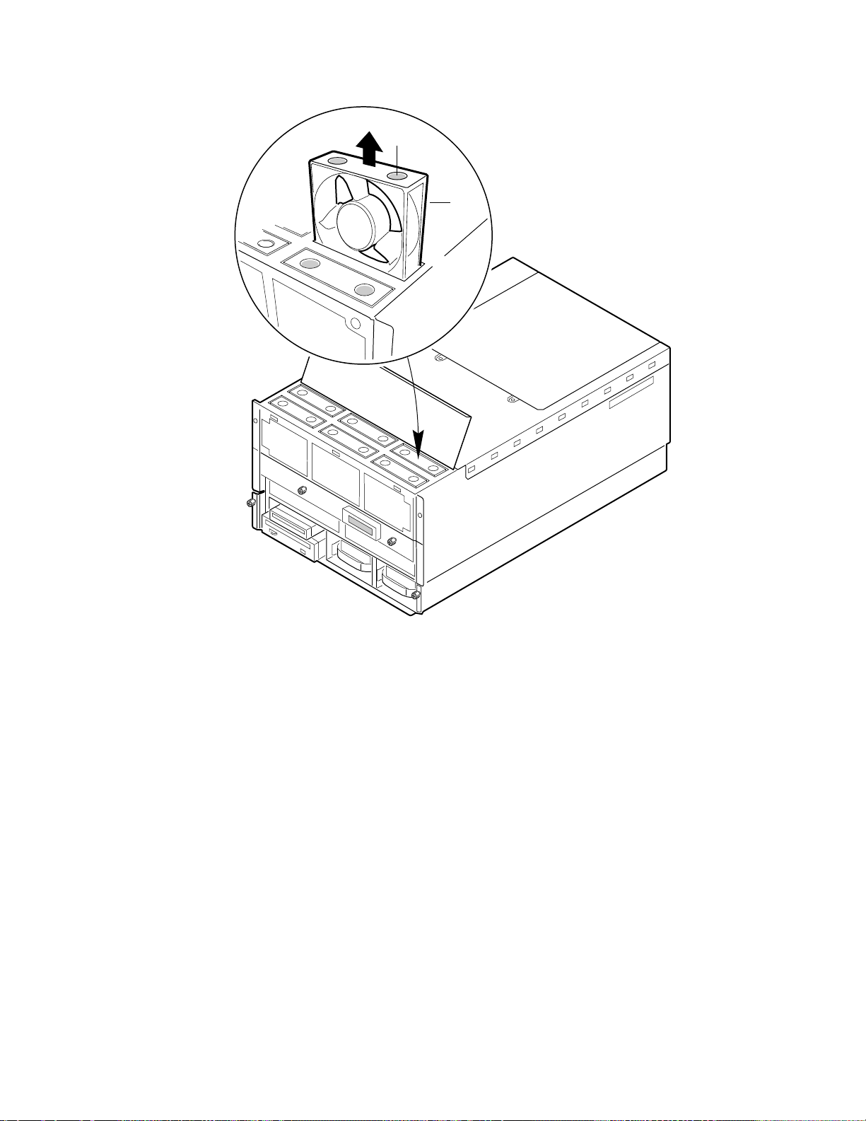
Chapter 9 Hot-swappable Fans: Hot Swapping
A
B
Figure 9-1. Removing/Hot-swapping a Fan
A. Grasp holes
B. Fan
OM07304
99
 Loading...