

Page 1

Intel® NetStructure™ 7110/7115 e-Commerce Accelerator
Version 2.3
User Guide
A31032-001
Page 2

Copyright
Copyright © 2000 Intel Corporation. All Rights Reserved.
This User Guide as well as the software described in it is furnished
under license and ma y only b e u sed or c opied in ac cordanc e with t he
terms of the license. The i nfo rm ation in this manual is fu rnished for
informational use only, is subject to change without notice, and
should not be con str ue d a s a commi tmen t by I nte l C or porat i on. Int el
Corporation assumes no responsibility or liability for any errors or
inaccuracies that may appear in this document or any software that
may be provided in association with this document.
Information in this document is provided in connection with Intel®
products. No license, express or imp lied, by estoppe l or otherwise, to
any intellectual prope rty rights is granted by this document. Excep t as
provided in Intel’s Terms and Conditions of Sale for such products,
Intel assumes no liability whatsoever, and Intel di sclaims any express
or implied warranty, relating to sale and/or use of Intel® products
including liability or warranties relating to fitness for a particular
purpose, merchantability, or infringement o f any patent, copyright or
other intellectual property right. Intel products are not intended for
use in medical, life saving, or life sustaining applications.
Intel may make changes to specificati ons and product descr iptions at
any time, without notice.
Trademarks
Intel, NetStructure™ 7110 e-Commerce Accelerator, and
NetStructure™ 7115 e-Commerce Accelerator are trademarks of or
trademarks applied for by Intel Corporation.
§ Other product and corporate names may be trademarks of other
companies and are used only for explanation and to the owners’
benefit, without intent to infringe.
Intel Corporation
Network Equipment Division
13280 Evening Creek Drive
San Diego, California 92128-4102
USA
July 28, 2000 A31032-001
Page 3

Table of Contents
Chapter 1: Introduction
About this User Guide . . . . . . . . . . . . . . . . . . . . . . . . . . . . . . . . . . . . . . . . . . . . . . . 1-1
New in This Release . . . . . . . . . . . . . . . . . . . . . . . . . . . . . . . . . . . . . . . . . . . . . . . . . 1-2
Who Should Use this Book. . . . . . . . . . . . . . . . . . . . . . . . . . . . . . . . . . . . . . . . . . . . 1-3
Before You Begin. . . . . . . . . . . . . . . . . . . . . . . . . . . . . . . . . . . . . . . . . . . . . . . . . . . 1-3
How to Use this Book. . . . . . . . . . . . . . . . . . . . . . . . . . . . . . . . . . . . . . . . . . . . . . . . 1-4
Chapter 2: Installation and Initial Configuration
Before You Begin. . . . . . . . . . . . . . . . . . . . . . . . . . . . . . . . . . . . . . . . . . . . . . . . . . . 2-1
Installing the 7110/7115 Free-Standing or in a Rack . . . . . . . . . . . . . . . . . . . . . . . . 2-2
Rack Installation . . . . . . . . . . . . . . . . . . . . . . . . . . . . . . . . . . . . . . . . . . . . . . . . . 2-2
Free-Standing Installation . . . . . . . . . . . . . . . . . . . . . . . . . . . . . . . . . . . . . . . . . . 2-3
Network Connections. . . . . . . . . . . . . . . . . . . . . . . . . . . . . . . . . . . . . . . . . . . . . . 2-3
Status Check. . . . . . . . . . . . . . . . . . . . . . . . . . . . . . . . . . . . . . . . . . . . . . . . . . . . . 2-4
Page 4

C O N T E N T S Intel® NetStructure™ 7110/7115 e-Commerce Accelerator User Guide
Network and Server LEDs . . . . . . . . . . . . . . . . . . . . . . . . . . . . . . . . . . . . . . . 2-4
Inline LED. . . . . . . . . . . . . . . . . . . . . . . . . . . . . . . . . . . . . . . . . . . . . . . . . . . . 2-4
Admin Terminal Connection . . . . . . . . . . . . . . . . . . . . . . . . . . . . . . . . . . . . . . . . 2-4
HyperTerminal§ Paste Operations. . . . . . . . . . . . . . . . . . . . . . . . . . . . . . . . . . . . 2-5
Troubleshooting . . . . . . . . . . . . . . . . . . . . . . . . . . . . . . . . . . . . . . . . . . . . . . . . . . . . 2-6
Server and Network LEDs . . . . . . . . . . . . . . . . . . . . . . . . . . . . . . . . . . . . . . . 2-6
Continuing Configuration . . . . . . . . . . . . . . . . . . . . . . . . . . . . . . . . . . . . . . . . . . 2-6
Chapter 3: Theory of Operation
Security. . . . . . . . . . . . . . . . . . . . . . . . . . . . . . . . . . . . . . . . . . . . . . . . . . . . . . . . . . . 3-1
Single Server Acceleration . . . . . . . . . . . . . . . . . . . . . . . . . . . . . . . . . . . . . . . . . . . . 3-1
Multiple Servers . . . . . . . . . . . . . . . . . . . . . . . . . . . . . . . . . . . . . . . . . . . . . . . . . . . . 3-2
Working with Internet Traffic Management (ITM) Devices . . . . . . . . . . . . . . . . . . 3-3
Positioning 7110/7115 between ITM Device and Client Network . . . . . . . . . . . 3-3
Positioning 7110/7115 between ITM Device and Server . . . . . . . . . . . . . . . . . . 3-4
Multiple 7110/7115s and Cascading Processing . . . . . . . . . . . . . . . . . . . . . . . . . . . 3-4
Scalability and Cascading . . . . . . . . . . . . . . . . . . . . . . . . . . . . . . . . . . . . . . . . . . 3-4
Spilling and Throttling. . . . . . . . . . . . . . . . . . . . . . . . . . . . . . . . . . . . . . . . . . . . . 3-4
Availability. . . . . . . . . . . . . . . . . . . . . . . . . . . . . . . . . . . . . . . . . . . . . . . . . . . . . . 3-5
Keys and Certificates . . . . . . . . . . . . . . . . . . . . . . . . . . . . . . . . . . . . . . . . . . . . . . . . 3-5
Cutting and Pasting with HyperTerminal§ . . . . . . . . . . . . . . . . . . . . . . . . . . . 3-6
Obtaining a Certificate from VeriSign§ or Other Certificate Authority . . . . . . . 3-7
Procedure. . . . . . . . . . . . . . . . . . . . . . . . . . . . . . . . . . . . . . . . . . . . . . . . . . . . . 3-7
Exporting a Key/Certificate from a Server . . . . . . . . . . . . . . . . . . . . . . . . . . . . 3-10
Apache Interface to Open SSL§ (mod_ssl). . . . . . . . . . . . . . . . . . . . . . . . . . 3-10
Apache SSL§. . . . . . . . . . . . . . . . . . . . . . . . . . . . . . . . . . . . . . . . . . . . . . . . . 3-11
Stronghold§. . . . . . . . . . . . . . . . . . . . . . . . . . . . . . . . . . . . . . . . . . . . . . . . . . 3-12
Importing into the 7110/7115 . . . . . . . . . . . . . . . . . . . . . . . . . . . . . . . . . . . . 3-12
Creating a new Key/Certificate on the 7110/7115. . . . . . . . . . . . . . . . . . . . . . . 3-14
Procedure. . . . . . . . . . . . . . . . . . . . . . . . . . . . . . . . . . . . . . . . . . . . . . . . . . . . 3-14
Global Site Certificates . . . . . . . . . . . . . . . . . . . . . . . . . . . . . . . . . . . . . . . . . . . 3-15
Overview. . . . . . . . . . . . . . . . . . . . . . . . . . . . . . . . . . . . . . . . . . . . . . . . . . . . 3-15
Global Site Certificate Paste Procedure . . . . . . . . . . . . . . . . . . . . . . . . . . . . 3-16
Redirection: Clients and Unsupported Ciphers . . . . . . . . . . . . . . . . . . . . . . . . . . . 3-17
Client Authentication . . . . . . . . . . . . . . . . . . . . . . . . . . . . . . . . . . . . . . . . . . . . . . . 3-18
Creating a Client CA Certificate using OpenSSL§ . . . . . . . . . . . . . . . . . . . . . . 3-20
SSL Processing . . . . . . . . . . . . . . . . . . . . . . . . . . . . . . . . . . . . . . . . . . . . . . . . . . . . 3-21
iv
Page 5

Table of Contents
Mapping. . . . . . . . . . . . . . . . . . . . . . . . . . . . . . . . . . . . . . . . . . . . . . . . . . . . . . . 3-21
Automapping. . . . . . . . . . . . . . . . . . . . . . . . . . . . . . . . . . . . . . . . . . . . . . . . . 3-21
Automapping with user-specified key and certificate. . . . . . . . . . . . . . . . . . 3-22
Automapping with multiple port combinations . . . . . . . . . . . . . . . . . . . . . . 3-22
Deleting automapping entries . . . . . . . . . . . . . . . . . . . . . . . . . . . . . . . . . . . . 3-22
Manual mapping . . . . . . . . . . . . . . . . . . . . . . . . . . . . . . . . . . . . . . . . . . . . . . 3-22
Combining automapping and manual mapping . . . . . . . . . . . . . . . . . . . . . . 3-23
Blocking. . . . . . . . . . . . . . . . . . . . . . . . . . . . . . . . . . . . . . . . . . . . . . . . . . . . . . . 3-23
Specific IP, Specific Port . . . . . . . . . . . . . . . . . . . . . . . . . . . . . . . . . . . . . . . 3-23
Subnet IP, Specific Port . . . . . . . . . . . . . . . . . . . . . . . . . . . . . . . . . . . . . . . . 3-24
All IPs, Specific Port. . . . . . . . . . . . . . . . . . . . . . . . . . . . . . . . . . . . . . . . . . . 3-24
Delete a Block. . . . . . . . . . . . . . . . . . . . . . . . . . . . . . . . . . . . . . . . . . . . . . . . 3-25
Failure Conditions, Fail-safe, and Fail-through . . . . . . . . . . . . . . . . . . . . . . . . . . . 3-26
Chapter 4: Scenarios
Syntax. . . . . . . . . . . . . . . . . . . . . . . . . . . . . . . . . . . . . . . . . . . . . . . . . . . . . . . . . . 4-2
Scenario 1—Single Server . . . . . . . . . . . . . . . . . . . . . . . . . . . . . . . . . . . . . . . . . . . . 4-3
Procedure for Scenario 1 . . . . . . . . . . . . . . . . . . . . . . . . . . . . . . . . . . . . . . . . . . . 4-3
Automapping. . . . . . . . . . . . . . . . . . . . . . . . . . . . . . . . . . . . . . . . . . . . . . . . . . 4-3
Manual Configuration. . . . . . . . . . . . . . . . . . . . . . . . . . . . . . . . . . . . . . . . . . . 4-3
Scenario 2—Multiple Servers . . . . . . . . . . . . . . . . . . . . . . . . . . . . . . . . . . . . . . . . . 4-5
Procedure for Scenario 2 . . . . . . . . . . . . . . . . . . . . . . . . . . . . . . . . . . . . . . . . . . . 4-5
Scenario 3—Multiple 7110/7115s, Cascaded. . . . . . . . . . . . . . . . . . . . . . . . . . . . . . 4-7
Assumptions. . . . . . . . . . . . . . . . . . . . . . . . . . . . . . . . . . . . . . . . . . . . . . . . . . . . . 4-7
Procedure for Scenario 3 . . . . . . . . . . . . . . . . . . . . . . . . . . . . . . . . . . . . . . . . . . . 4-8
Scenario 4—Different Ingress and Egress Routers . . . . . . . . . . . . . . . . . . . . . . . . 4-10
Procedure for Scenario 4 . . . . . . . . . . . . . . . . . . . . . . . . . . . . . . . . . . . . . . . . . . 4-10
Chapter 5: Command Reference
Online Help . . . . . . . . . . . . . . . . . . . . . . . . . . . . . . . . . . . . . . . . . . . . . . . . . . . . . . . 5-1
Command Line Interface . . . . . . . . . . . . . . . . . . . . . . . . . . . . . . . . . . . . . . . . . . . . . 5-2
User Authentication . . . . . . . . . . . . . . . . . . . . . . . . . . . . . . . . . . . . . . . . . . . . . . . 5-2
Command Line Prompt . . . . . . . . . . . . . . . . . . . . . . . . . . . . . . . . . . . . . . . . . . . . 5-2
Abbreviation to Uniqueness. . . . . . . . . . . . . . . . . . . . . . . . . . . . . . . . . . . . . . . . . 5-2
Moving the Insertion Point . . . . . . . . . . . . . . . . . . . . . . . . . . . . . . . . . . . . . . . . . 5-4
Command History . . . . . . . . . . . . . . . . . . . . . . . . . . . . . . . . . . . . . . . . . . . . . . . . 5-4
Cut and Paste . . . . . . . . . . . . . . . . . . . . . . . . . . . . . . . . . . . . . . . . . . . . . . . . . . . . 5-5
v
Page 6

C O N T E N T S Intel® NetStructure™ 7110/7115 e-Commerce Accelerator User Guide
Command Summary. . . . . . . . . . . . . . . . . . . . . . . . . . . . . . . . . . . . . . . . . . . . . . . . . 5-6
Command Reference. . . . . . . . . . . . . . . . . . . . . . . . . . . . . . . . . . . . . . . . . . . . . . . . 5-11
Help Commands. . . . . . . . . . . . . . . . . . . . . . . . . . . . . . . . . . . . . . . . . . . . . . . . . 5-11
Status Command . . . . . . . . . . . . . . . . . . . . . . . . . . . . . . . . . . . . . . . . . . . . . . . . 5-11
SSL Commands . . . . . . . . . . . . . . . . . . . . . . . . . . . . . . . . . . . . . . . . . . . . . . . . . 5-12
Port Mapping Commands . . . . . . . . . . . . . . . . . . . . . . . . . . . . . . . . . . . . . . . . . 5-22
Operational Commands . . . . . . . . . . . . . . . . . . . . . . . . . . . . . . . . . . . . . . . . . . . 5-25
Remote Management Commands . . . . . . . . . . . . . . . . . . . . . . . . . . . . . . . . . . . 5-27
Alarms and Monitoring Commands. . . . . . . . . . . . . . . . . . . . . . . . . . . . . . . . . . 5-34
Configuration Commands . . . . . . . . . . . . . . . . . . . . . . . . . . . . . . . . . . . . . . . . . 5-38
Administration Commands
Logging Commands. . . . . . . . . . . . . . . . . . . . . . . . . . . . . . . . . . . . . . . . . . . . . . 5-44
Chapter 6: Remote Management
Overview. . . . . . . . . . . . . . . . . . . . . . . . . . . . . . . . . . . . . . . . . . . . . . . . . . . . . . . . . . 6-1
Limitations. . . . . . . . . . . . . . . . . . . . . . . . . . . . . . . . . . . . . . . . . . . . . . . . . . . . . . 6-2
Remote Management CLI Commands. . . . . . . . . . . . . . . . . . . . . . . . . . . . . . . . . 6-2
Remote Telnet Sessions . . . . . . . . . . . . . . . . . . . . . . . . . . . . . . . . . . . . . . . . . . . . . . 6-4
Local Serial Console . . . . . . . . . . . . . . . . . . . . . . . . . . . . . . . . . . . . . . . . . . . . . . 6-4
Remote Console, Telnet. . . . . . . . . . . . . . . . . . . . . . . . . . . . . . . . . . . . . . . . . . . . 6-5
Changing the Telnet Port . . . . . . . . . . . . . . . . . . . . . . . . . . . . . . . . . . . . . . . . . . . 6-5
Disabling Telnet. . . . . . . . . . . . . . . . . . . . . . . . . . . . . . . . . . . . . . . . . . . . . . . . . . 6-6
Remote SSh Sessions . . . . . . . . . . . . . . . . . . . . . . . . . . . . . . . . . . . . . . . . . . . . . . . . 6-6
Local Serial Console . . . . . . . . . . . . . . . . . . . . . . . . . . . . . . . . . . . . . . . . . . . . . . 6-6
Remote Console, SSh. . . . . . . . . . . . . . . . . . . . . . . . . . . . . . . . . . . . . . . . . . . . . . 6-7
Changing the SSh Port. . . . . . . . . . . . . . . . . . . . . . . . . . . . . . . . . . . . . . . . . . . . . 6-7
Disabling SSh. . . . . . . . . . . . . . . . . . . . . . . . . . . . . . . . . . . . . . . . . . . . . . . . . . . . 6-8
SNMP . . . . . . . . . . . . . . . . . . . . . . . . . . . . . . . . . . . . . . . . . . . . . . . . . . . . . . . . . . . . 6-8
Standards Compliance . . . . . . . . . . . . . . . . . . . . . . . . . . . . . . . . . . . . . . . . . . . . . 6-9
Intel MIB Tree . . . . . . . . . . . . . . . . . . . . . . . . . . . . . . . . . . . . . . . . . . . . . . . . . . . 6-9
Supported MIBs . . . . . . . . . . . . . . . . . . . . . . . . . . . . . . . . . . . . . . . . . . . . . . 6-10
Where to find MIB Files . . . . . . . . . . . . . . . . . . . . . . . . . . . . . . . . . . . . . . . . 6-10
Enterprise Private MIB Summary . . . . . . . . . . . . . . . . . . . . . . . . . . . . . . . . . . . 6-11
Trap Summary . . . . . . . . . . . . . . . . . . . . . . . . . . . . . . . . . . . . . . . . . . . . . . . . . . 6-16
Standard SNMP Traps. . . . . . . . . . . . . . . . . . . . . . . . . . . . . . . . . . . . . . . . . . 6-16
Private Traps in ssl-appliance-mib.my . . . . . . . . . . . . . . . . . . . . . . . . . . . . . 6-16
Enabling SNMP . . . . . . . . . . . . . . . . . . . . . . . . . . . . . . . . . . . . . . . . . . . . . . . . . 6-17
vi
Page 7

Table of Contents
Specifying SNMP Information . . . . . . . . . . . . . . . . . . . . . . . . . . . . . . . . . . . 6-18
Community String. . . . . . . . . . . . . . . . . . . . . . . . . . . . . . . . . . . . . . . . . . . . . 6-19
Trap Community String . . . . . . . . . . . . . . . . . . . . . . . . . . . . . . . . . . . . . . . . 6-20
Access Control . . . . . . . . . . . . . . . . . . . . . . . . . . . . . . . . . . . . . . . . . . . . . . . . . . . . 6-21
Chapter 7: Alarms and Monitoring
Overview. . . . . . . . . . . . . . . . . . . . . . . . . . . . . . . . . . . . . . . . . . . . . . . . . . . . . . . . . . 7-1
Alarm Types . . . . . . . . . . . . . . . . . . . . . . . . . . . . . . . . . . . . . . . . . . . . . . . . . . . . . . . 7-3
ESC: Encryption Status Change Alarm . . . . . . . . . . . . . . . . . . . . . . . . . . . . . . . 7-3
Alarm Modifiers and Messages: . . . . . . . . . . . . . . . . . . . . . . . . . . . . . . . . . . . 7-3
RSC: Refused SSL Connections . . . . . . . . . . . . . . . . . . . . . . . . . . . . . . . . . . . . . 7-4
Alarm Modifiers and Messages. . . . . . . . . . . . . . . . . . . . . . . . . . . . . . . . . . . . 7-4
Extended Data. . . . . . . . . . . . . . . . . . . . . . . . . . . . . . . . . . . . . . . . . . . . . . . . . 7-4
RSC Alarm CLI Commands . . . . . . . . . . . . . . . . . . . . . . . . . . . . . . . . . . . . . . 7-4
UTL: Utilization Threshold Alarm . . . . . . . . . . . . . . . . . . . . . . . . . . . . . . . . . . . 7-5
Alarm Modifiers and Messages. . . . . . . . . . . . . . . . . . . . . . . . . . . . . . . . . . . . 7-5
Extended Data. . . . . . . . . . . . . . . . . . . . . . . . . . . . . . . . . . . . . . . . . . . . . . . . . 7-6
UTL Alarm CLI commands . . . . . . . . . . . . . . . . . . . . . . . . . . . . . . . . . . . . . . 7-6
OVL: Overload Alarm . . . . . . . . . . . . . . . . . . . . . . . . . . . . . . . . . . . . . . . . . . . . 7-7
Alarm Modifiers and Messages: . . . . . . . . . . . . . . . . . . . . . . . . . . . . . . . . . . . 7-7
Extended Data: . . . . . . . . . . . . . . . . . . . . . . . . . . . . . . . . . . . . . . . . . . . . . . . . 7-7
OVL Alarm CLI Commands: . . . . . . . . . . . . . . . . . . . . . . . . . . . . . . . . . . . . . 7-7
NLS: Network Link Status Alarm . . . . . . . . . . . . . . . . . . . . . . . . . . . . . . . . . . . 7-8
Alarm modifiers and messages: . . . . . . . . . . . . . . . . . . . . . . . . . . . . . . . . . . . 7-8
Extended Data: . . . . . . . . . . . . . . . . . . . . . . . . . . . . . . . . . . . . . . . . . . . . . . . . 7-8
Alarm Logging . . . . . . . . . . . . . . . . . . . . . . . . . . . . . . . . . . . . . . . . . . . . . . . . . . . . . 7-8
Monitoring . . . . . . . . . . . . . . . . . . . . . . . . . . . . . . . . . . . . . . . . . . . . . . . . . . . . . . . 7-13
Monitoring Reports . . . . . . . . . . . . . . . . . . . . . . . . . . . . . . . . . . . . . . . . . . . . . . 7-13
Report Configuration . . . . . . . . . . . . . . . . . . . . . . . . . . . . . . . . . . . . . . . . . . . . . 7-13
Monitoring Reports CLI Commands. . . . . . . . . . . . . . . . . . . . . . . . . . . . . . . 7-14
Chapter 8: Software Updates
Using Windows§ HyperTerminal§. . . . . . . . . . . . . . . . . . . . . . . . . . . . . . . . . . . . . . 8-2
Using Unix§ ‘cu’ and uuencoded image file . . . . . . . . . . . . . . . . . . . . . . . . . . . . . . 8-3
vii
Page 8

C O N T E N T S Intel® NetStructure™ 7110/7115 e-Commerce Accelerator User Guide
Chapter 9: Troubleshooting
Appendix A: Front Panel
Buttons and Switches . . . . . . . . . . . . . . . . . . . . . . . . . . . . . . . . . . . . . . . . . . . . . . . . A-2
Front Panel LEDs . . . . . . . . . . . . . . . . . . . . . . . . . . . . . . . . . . . . . . . . . . . . . . . . . . . A-2
Connectors . . . . . . . . . . . . . . . . . . . . . . . . . . . . . . . . . . . . . . . . . . . . . . . . . . . . . . . . A-4
Appendix B: Failure/Bypass Modes
Bypass Button. . . . . . . . . . . . . . . . . . . . . . . . . . . . . . . . . . . . . . . . . . . . . . . . . . . . . . B-2
Fail-through Switch (Security Level) . . . . . . . . . . . . . . . . . . . . . . . . . . . . . . . . . . . . B-2
Appendix C: Supported Ciphers
Cipher Strength. . . . . . . . . . . . . . . . . . . . . . . . . . . . . . . . . . . . . . . . . . . . . . . . . . . . . C-1
SSL Version Level . . . . . . . . . . . . . . . . . . . . . . . . . . . . . . . . . . . . . . . . . . . . . . . . . . C-2
Appendix D: Regulatory Information
Appendix E: Terms and Conditions and Software License
Glossary
Support Services
viii
Page 9

List of Figures
Mounting Bracket Orientation . . . . . . . . . . . . . . . . . . . . . . . . . . . . . . . . . . . . . . . . . 2-2
Wiring Connections . . . . . . . . . . . . . . . . . . . . . . . . . . . . . . . . . . . . . . . . . . . . . . . . . 2-3
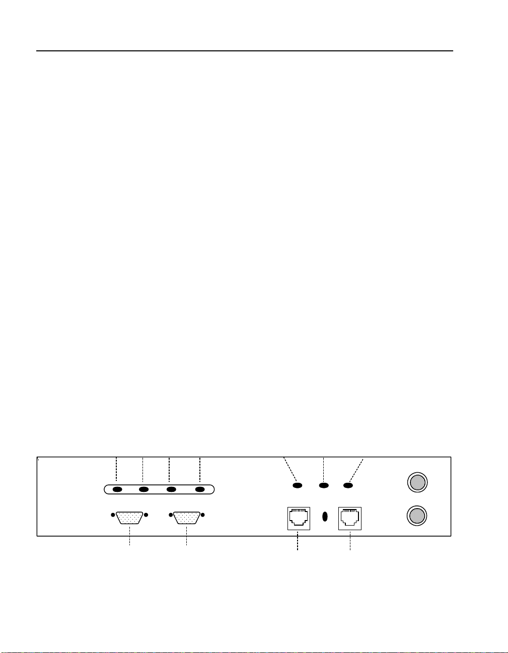
Front Panel Connectors and LEDs . . . . . . . . . . . . . . . . . . . . . . . . . . . . . . . . . . . . . . 2-4
7110/7115 in Single Server Configuration . . . . . . . . . . . . . . . . . . . . . . . . . . . . . . . 3-2
7110/7115 in Multiple Server Configuration . . . . . . . . . . . . . . . . . . . . . . . . . . . . . . 3-2
7110/7115 Between Router and ITM Device . . . . . . . . . . . . . . . . . . . . . . . . . . . . . 3-3
7110/7115s Between ITM Device and Servers . . . . . . . . . . . . . . . . . . . . . . . . . . . . 3-4
Cascaded 7110/7115s . . . . . . . . . . . . . . . . . . . . . . . . . . . . . . . . . . . . . . . . . . . . . . . 3-5
Single 7110/7115, Single Server Installation . . . . . . . . . . . . . . . . . . . . . . . . . . . . . 4-3
Single 7110/7115, Multiple Server Installation . . . . . . . . . . . . . . . . . . . . . . . . . . . . 4-5
Multiple (Cascaded) 7110/7115s . . . . . . . . . . . . . . . . . . . . . . . . . . . . . . . . . . . . . . . 4-8
Installation with Ingress and Egress Routers . . . . . . . . . . . . . . . . . . . . . . . . . . . . . 4-10
Page 10

F I G U R E S Intel® NetStructure™ 7110/7115 e-Commerce Accelerator User Guide
Intel’s MIB Tree (top level) . . . . . . . . . . . . . . . . . . . . . . . . . . . . . . . . . . . . . . . . . . . 6-9
Front Panel Connectors, Controls, and Indicators . . . . . . . . . . . . . . . . . . . . . . . . . . A-1
Front Panel Detail: Failure/Bypass Mode Controls and Indicators . . . . . . . . . . . . . B-2
xii
Page 11

Introduction
Congratulations on your choice of the Intel® NetStructure™ 7110/
7115 e-Commerce Accelerator. The processin g of secure transactions
through Secure Sock et Layer (SSL) ca n occupy up to 90% of even the
largest servers’ CPU power and can degrade response time
significantly. The 7110/ 711 5 pr ov ide s a completely transparent way
to increase the performance of Web sites for SSL transactions. The
7110/7115 is positioned in front of the server farm, where it intercep ts
SSL transactions, processes them, and rel ays them to the servers. The
7110/7115 performs all encryption and decryption management in
this environment with a minimum of administrator interaction.
About this User Guide
This User Guide supports the Intel® NetStructure™ 7110 e-Commerce Accelerator and the Intel ® NetStructure™ 7115 e-Commerce
Accelerator. By default this text refers to the product as “7110/71 15.”
Where appropriate, the text refers to “7110” or “7 115.” Additional ly,
notes in the left -hand margin may be used to distinguish th e two products. Illustrations of the command prompt use “
Intel 7115>.”
Page 12

C H A P T E R 1 Intel® NetStructure™ 7110/7115 e-Commerce Accelerator User Guide
New in This Release
New features in the Intel® NetStructure™ 7110/7115 e-Commerce
Accelerator include:
• Impro ved performance: Threefo ld in crease in S SL connect ions
processed per second—from 200 to 600 (7115 only)
• More certificate mappings: Up to 1000 certificate mappings
supported
• Remote Management:
• Telnet—standard remote access to the Command Line
Interface (CLI) with new “Console Monitoring” features
• SSh—complete, secure CLI access with new “Console
Monitoring” features
• SNMP—Includes both Private Enterprise MIB and MIBII
functionality
• Alarms: The 7110/7115 can be configured to display—at the
administration console or a remote management session (Telnet
and SSh)—autonomous one-line reports of the following
exceptional conditions:
1-2
• Encryption status change
• Refused SSL connect i ons
• T hreshol d alerts
• Overload alerts
• Network link status
Page 13

C H A P T E R 1 Who Should Use this Book
• Monitoring: Users can now configure the 7110/7115 to send
periodic multi-status reports to the administration console or a
remote management session (Telnet and SSh). Monitor reports
include such information as:
• Inline/bypass mode
• Failsafe/failthrough mode
•CPU status
• S SL connections status
• Network interface status
• Server interface status
• Rate of encryption/decryption
Who Should Use this Book
This User Guide is intended for administrators with the following
background:
• Familiarity with networking concepts and terminology.
• Basic knowledge of network topologies.
• Basic knowledge of networks and IP routing.
• Some knowledge of SSL, keys, and certificates.
• Knowledge of Web servers.
Before You Begin
7110/7115 setup can be divided into three basic procedures:
• Physically install single or multiple 7110/7115s with single or
multiple servers.
• Configure your 7110/7115 in the Command Line Interface.
• Identify existing certificates or obtain new ones you wish to use
in SSL operations.
1-3
Page 14

C H A P T E R 1 Intel® NetStructure™ 7110/7115 e-Commerce Accelerator User Guide
How to Use this Book
The information in this book is organized as follows:
• Chapter 1: Introduction provides an introduction and overview
of the 7110/7115, and a summary of new features.
• Chapter 2: Installation and Initial Configuration contains
installation and initia l configurat ion procedur es. (This material is
also discussed in the separate Quick Start Guide.)
• Chapter 3: Theory of Operation explains the general principles
behind 7110/7115 operation.
• Chapter 4: Scenarios provides examples of 7110/7115
configurations, together with specific procedures for their
implementation.
• Chapter 5: Command Reference explains the Command Line
Interface (CLI), and lists the commands and their functions.
• Chapter 6: Remote Management detail s how you can use Telnet,
Secure Shell (SSH), and SNMP to manage the 7110/7115 from
remote locations.
1-4
• Chapter 7: Alarms and Monitoring explains the ways in which
you can configure the device to report information to you, either
routinely or as a result of abnormal events or conditions.
• Chapter 8: Software Updates provides procedures for obtaining
7110/7115 system software updates.
• Chapter 9: Troubleshooting is a table containing symptoms of
problems you may encounter with corresponding likely causes
and remedies.
• Appendix A: Front P anel diagr ams and explains the 7110 /7115’s
front panel LEDs, buttons, and connections.
• Appendix B: Failure/Bypass Modes explains how the 7110/7115
deals with failure conditions and details the bypass function.
• Appendix C: Supported Ciphers lists the supported encryption
ciphers.
• Appendix D: R egulatory Information provides information
regarding the 7110/7115’s compliance with applicable
regulations.
Page 15

C H A P T E R 1 How to Use this Book
• Appendix E: Terms and Conditions contains the software license
and terms and conditions of user of this product.
• Glossary defines terms appearing in this User Guide.
1-5
Page 16

C H A P T E R 1 Intel® NetStructure™ 7110/7115 e-Commerce Accelerator User Guide
Notes
1-6
Page 17

Installation and Initial Configuration
Intel® NetStructure™ 7110/7115 e-Commerce Accelerator
installation and initial configuration instruc tions are in this chapte r.
Before You Begin
WARNING: Do not
remove the cover. There
are no user-servicable
parts inside.
Before you begin installation, you need the following:
• IP address for 7110/7115 (only if you intend to use the Remote
Management)
• IP addresses and ports of servers.
• Keys/certificates. See Chapter 3 for information on obtaining
keys and certificates.
• Network cables, such as straight-through and/or crossover
cables. (Procedures in the section,“Wiring Connections” in this
chapter will ident ify t he ty pes of cables you must use.) If you are
installing the 7110/7115 in a rack, you will also need:
• Phillips screwdriv e r
• Rack-mounting screws
Page 18

C H A P T E R 2 Intel® NetStructure™ 7110/7115 e-Commerce Accelerator User Guide
Installing the 7110/7115 FreeStanding or in a Rack
The Intel® NetStructure™ 7110/7115 e-Commerce Accelerator is
physically installed in either of two ways:
• In a standard 19” rack, cantilevered from the provided mounting
brackets
• Free-standing on a flat surface with sufficient space for air-flow
Rack Installation
Rack mounting requires the use of the mount ing brackets, and all four
of the included Phillips screws.
1. Locate the two mounting brackets and the four screws. (Two
screws for each bracket.)
2. Attach a mounting bracket to each side of the 7110/7115, using
two of the provided screws for each bracket. Use the holes near
the front of the 7110/7115’s sides. The brackets have both round
and oval holes; the flange with round holes attaches to the 7110/
7115, the oval holes to the rack.
2-2
Figure 2-1: Mounting Bracket Orientation
Page 19

C H A P T E R 2 Installing the 7110/7115 Free-Standing or in a Rack
3. Position the 7110/7115 in the desired space of your 19” rack and
attach the front flange of each mounting bracket to the rack with
two screws each. (Rack-mounting screws are not provided.)
Free-Standing Installation
1. Attach the provided self-adhesive rubber feet to the 7110/7115’s
bottom.
2. Place the 7110/7115 on a flat surface and make sure that there is
adequate airflow surrounding the unit (allow at least one inch of
air space on all sides).
Network Connections
1. Use the “Network Cable Require ments ” t able near the beginning
of this guide to select and install the the appropria te cables.
NOTE: Never connect
both ports to the same
network segment (e.g., to
the same hub or switch).
Doing so creates a
feedback loop that
adversely effects network
bandwidth.
Hub/Router/Switch
2. Connect the provided power cable to the bac k of the unit . (Ther e
is no power switch.) Under no rmal circumstan ces, the 71 1 0/71 1 5
requires approximately 30 seconds to boot. When the boot is
complete, the unit’s Power LED is steadily illuminated. (If the
Power LED is not steadil y illuminated, see Chapte r 9,
“Troubleshooting.)
3. If the Inline LED is neither steadily illuminated or blinking, press
the Bypass switch.
4. At this point both the Network and Server LEDs should be
steadily illuminated. If not, please see Chapter 9,
“Troubleshooting.
Intel® NetStructure™ 7110/7115 e- Commer ce Acc elerators
Server
Figure 2-2: Wiring Connections
2-3
Page 20
C H A P T E R 2 Intel® NetStructure™ 7110/7115 e-Commerce Accelerator User Guide
Status Check
Before proceeding to the PC In it i al iza ti on sect i on, t ake a moment to
verify that the 7110/7115 is correctly connected.
Network and Server LEDs
Verify that the Network and Server LEDs are both illuminated. If one
or both are not, ref er to the T roubleshoot ing section at the end of this
chapter .
Inline LED
A blinking Inline LED indicates that t he system is online i n Fail-safe
mode. Refer the T roubleshooting section at the end of this chapter or
Appendix B, “Failure/Bypass Modes.”
Admin Terminal Connection
Run HyperTerminal§ or a similar termin al emulator on your PC. The
steps below are illustrative of HyperTerminal§. Other terminals will
require different procedures.
2-4
1. Use the serial cable provided with the 7110/7115 to connect the
device’s serial port (the left-hand serial port labeled “Console”)
to the serial port of any terminal. (A PC running Windows
HyperTerminal§ is used here as an example.)
Power Error Overload Activity
(green) (red) (amber) (green)
Console
Aux Console
Figure 2-3: Front Panel Connectors and LEDs
Network Link
(green)
Network Link
(RJ45)
Inline
(green)
Server Link
(green)
Server Link
(RJ45)
Page 21

C H A P T E R 2 Installing the 7110/7115 Free-Standing or in a Rack
2. Type an appropriate name in the Name field of the Connection
Description window (e.g., “Configuration”), and then click the
OK button. The Phone Number panel appears.
3. In the Connect Using… field specify “Direct to COM1” (or the
serial port through wh ich th e PC is co nnected to the 7 1 10 /7 1 15 if
different from COM1).
4. Click the OK button. The COM1 Properties panel appears. Set
the values displayed here to 9600, 8, none, 1, and none.
5. Click the OK button.
HyperTerminal§ Paste Operations
If you’re using Hyperterminal§ you must make the following
configuration change:
1. In the File menu, click Properties.
2. Click the Settings tab.
3. Click the ASCII Setup button.
4. Change the values of Line and Character delay from 0 to at least
1 millisecond.
5. Click OK twice to exit.
2-5
Page 22

C H A P T E R 2 Intel® NetStructure™ 7110/7115 e-Commerce Accelerator User Guide
T roubleshooting
Server and Network LEDs
If either the Network or Server LED fails to illuminate using either
straight-through or crossover network cables, the problem may be
elsewhere in the network. Verify by wiring around the 7110/7115.
Inline LED
The Fail-through switch allows you to control what happens in the
event of a failure. It is located in a recess between the Network and
Server connectors. Use a small screwdriver or paper clip to
manipulate the switch. The two options are:
• Allow traffic to flow through the 7110/7115 unprocessed. (Fail-
through mode, indicated by a steadily illuminated Inline LED.)
• Block traffic flow through the 7110/7115 entirely. (Fail-safe
mode, indicated by a blinking Inli ne LED.)
Please see Appendix B for a table describing all permutatio ns of LED
operation.
2-6
Continuing Configuration
This concludes basic configuration of the 7110/7115. To configure
the unit for production please continue with Chapter 3, Theory of
Operations, or Chapter 4, Scenarios.
Page 23

Theory of Operation
Security
New in the Intel® NetStructure™ 7110/7115 e-Commerce
Accelerator is Remote Management cap ability. Thi s feature requires
that the 7110/7115’s network interface be assigned an IP address,
thus security becomes a matter for your attention. If you intend to
manage your 7110/7115 from a remote location, be sure to read the
section “Access Control,” Chapter 6, “Remote Management.”
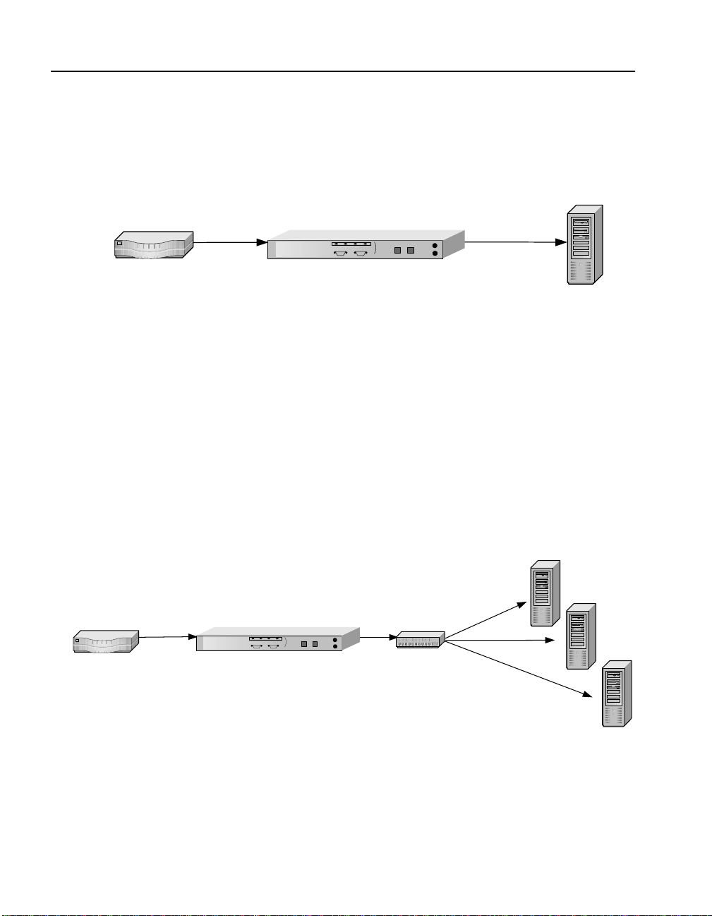
Single Server Acceleration
Typically, the Intel® NetStructure™ 7110/7115 e-Commerce
Accelerator supports the SSL processing needs of a single server.
This is the simplest and most common con figuration. The 7110/7115
is connected to the network between the router and the server.
Page 24
C H A P T E R 3 Intel® NetStructure™ 7110/7115 e-Commerce Accelerator User Guide
Ideally, the 7110/7115 is located in the same rack as the server,
separated by a short distance. .
Intel® NetStructure™ 7110/7115 e-Commerce Accelerator
Router
Single Server
Figure 3-1: 7110/7115 in Single Server Configuration
Multiple Servers
Given the SSL processing power of the 7110/7115, multiple servers
can be supported. In this configuration, the 7110/7115 sits between
the router and th e switch. SSL traf fic intended for these s erv ers is
intercepted and other traffic is passed through.
3-2
Server 1
Server 2
hub/switchRouter
Server 3
Intel® NetStructure™ 7110/7115
e-Commerce Accelerator
Figure 3-2: 7110/7115 in Multiple Server Configuration
Page 25
C H A P T E R 3 Working with Internet Traffic Management (ITM) Devices
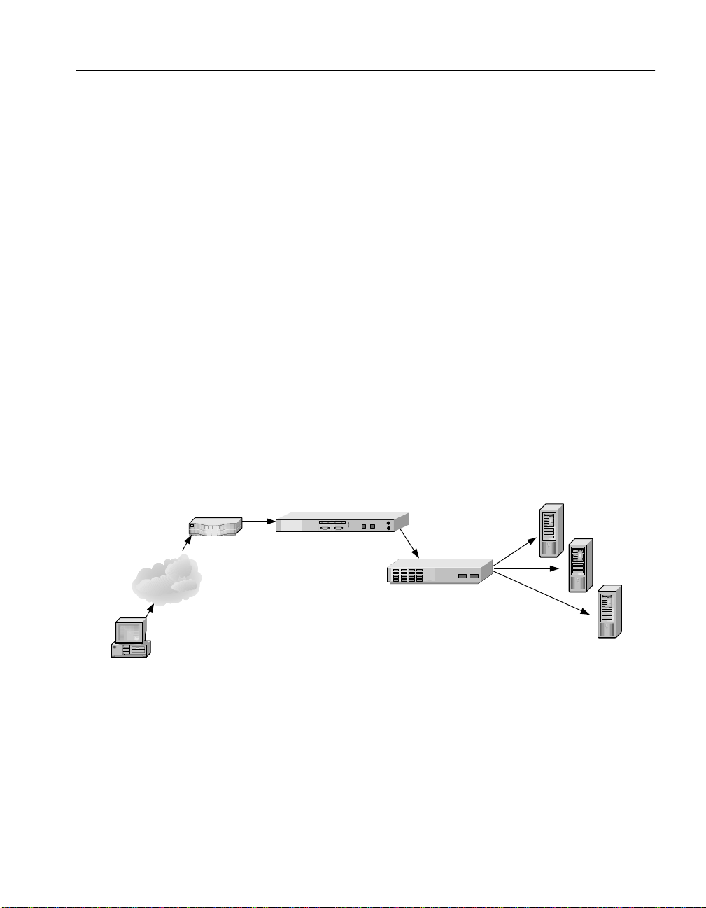
Working with Internet Traffic Management (ITM) Devices
The 7110/7115 is compatible with Internet Traffic Management
(ITM) devices. In such environments, the 7110/7115 lies b etween the
router and the ITM device, or bet ween the ITM device and the se rver.
ITM devices distribute workload across multiple servers and redirect
traffic based on content.
Positioning 7110/7115 between ITM Device and Client Network
If the ITM device supports layer 7 traffic management, URLs must
be readable (that is, unencrypted), thus in environments performing
layer 7 load balancing, it is recommended that the 7110/7115 be
placed between the ITM device and the client network.
Client
Internet
Intel® NetStructure™ 7110/7115 e-Commerce Accelerator
Router
ITM Device
Figure 1-3: 7110/7115 Between Router and ITM Device
Server 1
Server 2
Server 3
3-3
Page 26
C H A P T E R 3 Intel® NetStructure™ 7110/7115 e-Commerce Accelerator User Guide
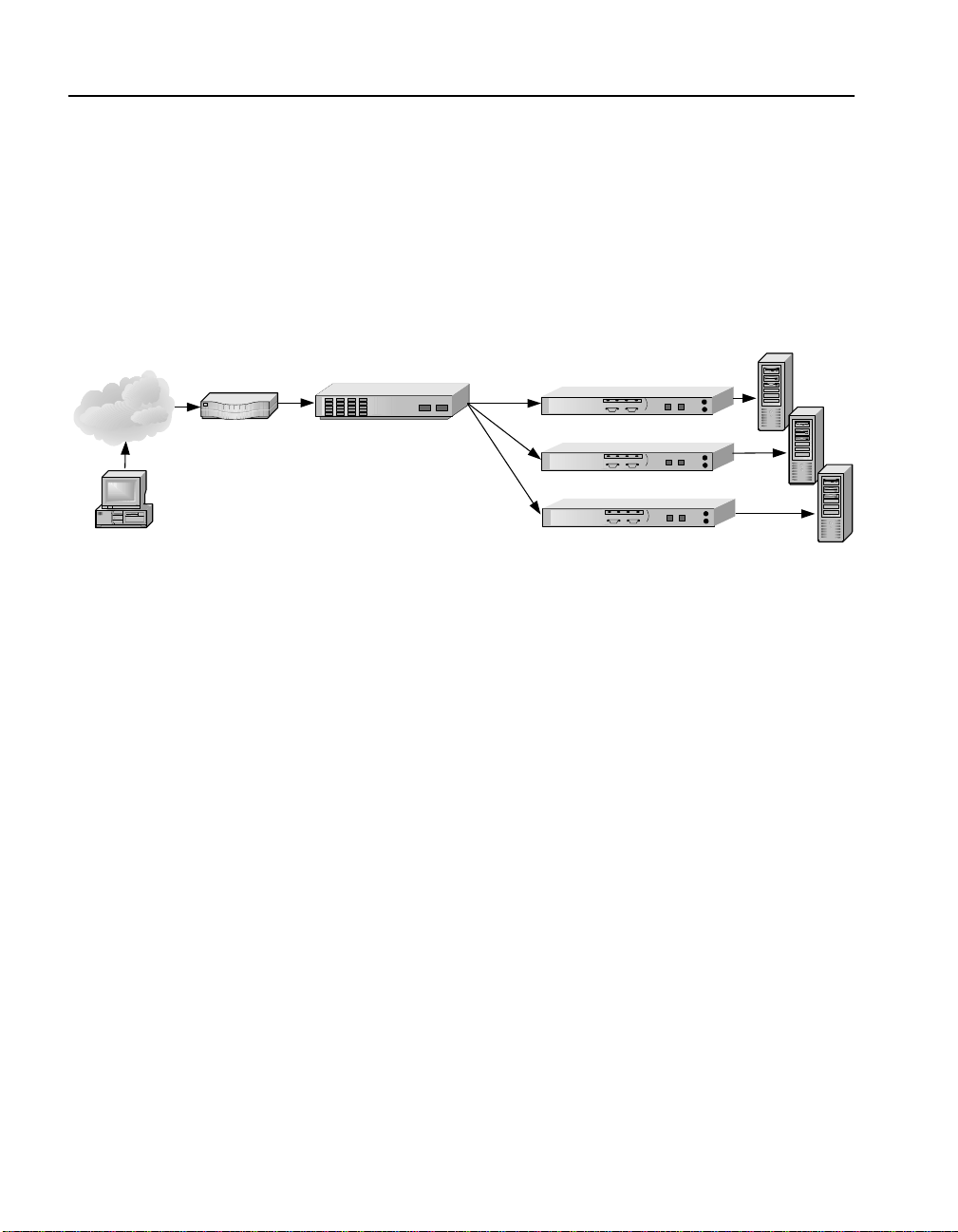
Positioning 7110/7115 between ITM Device and Server
If security considerations require limited net work access to clear text,
the 7110/7115 should be placed between the ITM device and the
server.
Intel® NetStructure™ 7110/7115
e-Commerce Accelerators
int l
e
int l
e
int l
e
Servers
Internet
Client
Router
ITM Device
NOTE: The
configuration in Figure
1-4 precludes layer 7
load balancing because
secure traffic through the
ITM device is encrypted.
Figure 1-4: 7110/7115s Between ITM Device and Servers
Multiple 7110/7115s and Cascading Processing
Scalability and Cascading
The 7110/7115’s capabilities are scalable by chaining, or
“cascading,” multiple 7110/7115s together. In such configurations,
each unit’s server side connector is wired to the network side
connector of the next 7110/ 7115 in line. The last 711 0/7115 in line is
connected to the server, switch, or ITM device.
Spilling and Throttling
When the 7110/7115’ s “spill” opt ion is enabled, if a given 711 0/7115
cannot process a request within a specified interval, the request is
passed on, still encrypted, to the next 7110/7115 in line. The last
3-4
Page 27

C H A P T E R 3 Keys and Certificates
7110/7115 on the server side can also be enabled to spill to the server.
Spilling is performed dynamically on a connection-by-connection
basis. (See spill command, Chapter 5, “Command Reference.”) If
spill is disabled, the 7110/7115 “throttles,” that is, will not accept
incoming requests when it becomes overloaded.
Intel® NetStructure™ 7110/7115 e-Commerce
Accelerators
Hub/Router/Switch
Figure 3-5: Cascaded 7110/7115s
Availability
When a 7110/7115 fails or is set t o Bypass mode while Fail-through
is enabled, the 7110/7115’s network side and server side network
adapters are directly conn ected, allowing traffic to pass throu gh to the
next device until the fa iled unit is brought back into service. This
feature eliminates a single point of failure and provides a high level
of availability, should there be a failure. In installations with multiple
7110/7115s, the next unit in the cascade picks up the encryption/
decryption workload, while in single 7110/7115 configurations, the
server assumes the load. See“Failure/Bypass Modes in Appendix B
for more information.
Server
WARNING: The 7110/
7115 comes with default
keys and certificates for
test purposes, however
certificates for
production use should be
obtained from a
recognized certificate
authority.
Keys and Certificates
A necessary part of the 7110/7115 configuration is the use of keys
and certificates. A key is a set of numbers used to encrypt or decryp t
data. A certificate is a “form” that identifies a server or user. The
certificate contains information about your company as well as
information from a third party that verifies your identity.
3-5
Page 28

C H A P T E R 3 Intel® NetStructure™ 7110/7115 e-Commerce Accelerator User Guide
There are three ways to obtain keys and certificates:
• Obtaining a certificate from VeriSign§ or other certificate
authority
• Using an existi ng key/certificate
• Creating a new key/certificate on the 7110/7115
Cutting and Pasting with HyperT ermi nal§
Cutting and pasting is an integ ral part of t he next several proc edures.
Below are procedures for cutting and pasting in HyperTerminal§. If
you use some other terminal program, consult that product’s
documentation for appropriate procedures.
To copy an item (key, certificate signing request, etc.) from
HyperTerminal§:
1. Open the HyperTerminal§ window.
2. Click and drag to select the item.
3. After the item is selec ted, open th e Edit menu and cli ck Co py (or
type <ctrl-c>).
3-6
4. Open the window where you will paste the data, and posit io n the
cursor at the appropriate point.
5. In the Edit menu, click Paste (or type <ctrl-v>).
To paste an item (key, certificate signing request, etc.) into
HyperTerminal§:
1. Display the item in the appropriate applic ation window, then
click and drag to select the item.
2. Once the item is selected, click the Edit menu and select Copy
(or type <ctrl-c>).
3. Move to the HyperTerminal§ window, and position the cursor at
the appropriate point.
4. Pull down the Edit menu, and select Paste to Host (or type
<ctrl-v>).
Page 29

C H A P T E R 3 Keys and Certificates
Obtaining a Certificate from V eriSign§ or Other Certificate Authority
Use the create key command to create your key and the create sign
command to create a signing request to be sent to VeriSign or other
certificate authority for authentication. The certificate authority will
return it in approximately one to five days. After you have received
the certificate, use the import cert command to import it into the
7110/7115.
The fields input to create a signing request are called collectively a
Distinguished Name (DN). For optimal security, one or more fields
must be modified to make the DN unique.
Procedure
Create a key:
1. Type the create key command at the prompt:
Intel 7115> create key
Key strength (512 /1024) [512]:
New keyID [001]: 002
Keypair was created for keyID: 002
2. Create a Certificate Signing Request:
Intel 7115> create sign 002
You are about to be asked to enter information
that will be incorporated into your
certificate request. The "common name" must be
unique. For other fields, you could use
default values.
Certifying authoritie s have specific guidelines o n how to answer each
of the questions. These guidelines may vary by certifying authority.
Please refer to the guid elines of the cer tifying a uthorit y to who m you
submit your Certificate Signing Request (CSR). Please keep the
following in mind when entering the i nformation that will be
incorporated into your certificate request:
• Country code: This is the two-letter ISO abbreviation for your
country (for example, US for the United States).
• State or Province: This is the name of the state or province
where your organization’s head of fice is lo cat ed. Pl ease enter the
full name of the state or province. Do not abbreviate.
3-7
Page 30

C H A P T E R 3 Intel® NetStructure™ 7110/7115 e-Commerce Accelerator User Guide
• Locality: This is usually the name of the city where your
organization’s head office is located.
• Organization: This should be the organization that owns the
domain name. The organization name (corporation, limited
partnership, university, or government agency) must be
registered with some author it y at th e national, state, or city level.
Use the legal name under which your organization is registered.
Please do not abbreviate your or ganizat ion’s name and do not use
any of the following characters: < > ~ ! @ # $ % ^ * / \ ( ) ?.
• Organizational unit: This is normally the name of the
department or group that will use the certificate.
• Common name: The common name is the “fully qualified
domain name,” (or FQDN) used for DNS lookups of your server
(for example, www.mysite.com). Browsers use this information
to identify your Web site. Some browsers will refuse to establish
a secure connection with your site if the server name does not
match the common name in the certificate. Please do not include
the protocol specifier “http://” or any port number s or pathnames
in the common name. Do not u se wildcard c haracters such as * or
?, and do not use an IP address.
3-8
• E-mail address: This should be the e-mail address of the
administrator responsible for the certificate.
3. Export the Certificate Signing Request (CSR).
In this example, xmod em i s used t o se nd the CSR to a PC connec ted
to the console port.
Intel 7115> export sign mywebserver
Export protocol: (xmodem, uuencode, ascii)
[ascii]:x <Enter>
Use Ctrl-x to kill transmission
Beginning export...
Export successful!
Intel 7115>
To submit the CSR to a certifying authority, paste it into the field
provided in the authority’s online request form. Remember to include
the “-----BEGIN CERTIFICATE REQUEST-----” and “-----END
CERTIFICATE REQUEST-----” lines.
Page 31

C H A P T E R 3 Keys and Certificates
Typically, the CSR will look som e th ing like this:
-----BEGIN CERTIFICATE REQUEST----MIIBnDCCAQUACQAwXjELMAkGA1UEBhMCQ0ExEDOABgNVBAgT
B09udGFayW8xEDAOBgNVBAcTB01vbnRyYWwxDDAKBgNVBAoT
A0tGQzEdMBsGA1UEAxMUd3d3Lmlsb3ZlY2hpY2tlbi5jb20w
gZ0wDQYJKoZIhvcNAQEBBQADgYsAMIGHAoGBALmJA2FLSGJ9
iCF8uwfPW2AKkyyKoe9aHnnwLLw8WWjhl[ww9pLietwX3bp6
Do87mwV3jrgQ1OIwarj9iKMLT6cSdeZ0OTNn7vvJaNv1iCBW
GNypQv3kVMMzzjEtOl2uGl8VOyeE7jImYj4HlMa+R168AmXT
82ubDR2ivqQwl7AgEDoAAwDQYJKoZIhvcNAQEEBQADgYEAn8
BTcPg4OwohGIMU2m39FVvh0M86ZBkANQCEHxMzzrnydXnvRM
KPSE208x3Bgh5cGBC47YghGZzdvxYJAT1vbkfCSBVR9GBxef
6ytkuJ9YnK84Q8x+pS2bEBDnw0D2MwdOSF1sBb1bcFfkmbpj
N2N+hqrrvA0mcNpAgk8nU=
-----END CERTIFICATE REQUEST-----
4. When the certificate authority returns the certificate, import it
into the 7110/7115. Use the import cert command, with the
KeyID. As with the import key, choose an import protocol for
importing the key . Use p for paste. After the paste is finished, add
three periods to display the command line.
Intel 7115> import cert mywebserver
keyid is mywebser ver;
Import protocol: (paste, xmodem, uudecode)
[paste]: <Enter>
Type or paste in date, end with ... alone on line
-----BEGIN CERT IFICATE----MIIDKDCCAtKgA wIBAgIBADANBg kq hkiG9w0BAQQFA DCB nDEL
MAkGA1UEBhMCV VMxCzAJBgNVBA gT AkNBMQ4wDAYDV QQH EwVQ
b3dheTEaMBgGA 1UEChMRQ29tbW Vy Y2Ug
.
.
.
-----END CERTIF ICATE----- <Enter>
... <Enter>
Import successful!
Intel 7115>
3-9
Page 32

C H A P T E R 3 Intel® NetStructure™ 7110/7115 e-Commerce Accelerator User Guide
5. Create mapping for Server 1. Use the create map command to
specify the server IP address, ports, and keyID.
Intel 7115> create map
Server IP (0.0.0.0): 10.1.1.30
SSL (network) port [443]: <Enter>
Cleartext (server) port [80]: <Enter>
KeyID to use for mappi ng: mywebserver
6. Save the configuration when the server has been mapped.
Intel 7115> config save
Saving configuration to flash...
Configuration saved to flash
Intel 7115>
Using an Existing Key/Certificate
Exporting a Key/Certificate from a Server
This method is used when it is important that the existing keys and
certificates are used.
NOTE: Currently there
is no published method
for extracting private
keys from Microsoft IIS
or Netscape servers.
3-10
Consult your server software documentation f or detailed instructions
on how to export keys and certificates. Once you have exported the
keys and certificates, use the import key and import cert commands
to paste the keys an d ce rti ficates into your 7110 /7115. Some general
instructions are provided below for the Apache Web Server.
Apache Interface to Ope n SSL§ (mod_ssl)
For key:
1. Look in $APACHEROOT/conf/httpd.conf for location of *.key
file.
2. Copy and paste the key file.
For certificate:
1. Look in $APACHEROOT/conf/httpd.conf for location of *.crt
file (certificate).
2. Copy and paste the certificate file.
Page 33

C H A P T E R 3 Keys and Certificates
Apache SSL§
For key:
1. Look in $APACHESSLROOT/conf/httpd.conf for location of
*.key file.
2. Copy and paste the key file.
For certificate:
1. Look in $APACHESSLROOT/conf/httpd.conf for location of
*.cert file.
2. Copy and paste the certificate file.
3-11
Page 34

C H A P T E R 3 Intel® NetStructure™ 7110/7115 e-Commerce Accelerator User Guide
Stronghold§
For key:
1. Look in $STRONGHOLDROOT/conf/httpd.conf for location of
*.key file.
2. Copy and paste the key file.
For certificate:
1. Look in $STRONGHOLDROOT/conf/httpd.conf for location of
*.cert file.
2. Copy and paste the certificate file.
Importing into the 7110/7115
1. Use the import key command with the keyID, and choose an
import protocol fo r importi ng the k ey. In this case, use the default
to “paste.” When the paste is finished, add a line break followed
by three periods to display the command line.
Intel 7115> import key mywebserver
Import protocol: (paste, xmodem, uudecode)
[paste]: <Enter>
Type or paste in date, end with ... alone on line
-----BEGIN RSA PRIVATE KEY----MIIBOgIBAAJBALGOlBH14vIdtfuA+UnyRIoKya13ey8mj3GD
QakdwoDJALu+jtcC
.
.
.
S9dPdwp6zctsZ eztn/ewPeNamz 3q 8QoEhY8CawEA
-----END RSA PRIVATE KEY-----<Enter>
... <Enter>
Import successful!
Intel 7115>
3-12
Page 35

C H A P T E R 3 Keys and Certificates
2. Use the import cert command with the keyID. As with import
key, choose an import protocol for importing the key. Use the
default to “paste.” When the paste is finished, add a line break
followed by three periods to display the command line.
Intel 7115> import cert mywebserver
keyid is mywebser ver;
Import protocol: (paste, xmodem, uudecode)
[paste]: <Enter>
Type or paste in date, end with ... alone on line
-----BEGIN CERT IFICATE----MIIDKDCCAtKgA wIBAgIBADANBg kq hkiG9w0BAQQFA DCB nDEL
MAkGA1UEBhMCV VMxCzAJBgNVBA gT AkNBMQ4wDAYDV QQH EwVQ
b3dheTEaMBgGA 1UEChMRQ29tbW Vy Y2Ug
.
.
.
-----END CERTIF ICATE----- <Enter>
... <Enter>
Import successful!
Intel 7115>
3. Create a server mapping. Use the create map command to
specify the server IP address, ports, and keyID.
Intel 7115> create map
Server IP (0.0.0.0): 10.1.1.30
SSL (network) port [443]: <Enter>
Cleartext (server) port [80]: <Enter>
KeyID to use for mappi ng: mywebserver
4. Save the configuration when the server has been mapped.
Intel 7115> config save
Saving configuration to flash...
Configuration saved to flash
Intel 7115>
3-13
Page 36

C H A P T E R 3 Intel® NetStructure™ 7110/7115 e-Commerce Accelerator User Guide
Creating a new Key/Certificate on the 7110/7115
Use the create key and create cert comman ds to create new keys and
certificates for 7110/7115 operation. This procedure can be used
when there are no existing keys and certificates on the server. The
advantage is that this method is very fast, but a certificate authority
has not signed the certificates.
The fields input to create a certificate are called a Distinguished
Name (DN). For optimal security, one or more fields must be
modified to make the DN unique.
Procedure
1. Create a key as follows:
Intel 7115> create key
Enter the key strength [512,1024]: 512
New keyID [001]: mywebserver
Keypair was created for keyID: mywebserver
2. Enter the create cert command with the keyID
Intel 7115> create cert mywebserver
You are about to be asked to enter information…
3-14
Enter the information for the certificat e, as prompted:
• Country
• State
• Locality
• Organization
• Organization unit
• Common name (for example, www.myserver.com)
• E-mail address.
3. Create a server mapping. Use the create map command to
specify the server IP address, ports, and keyID.
Intel 7115> create map
Server IP (0.0.0.0): 10.1.1.30
SSL (network) port [443]: <Enter>
Cleartext (server) port [80]: <Enter>
KeyID to use for mappi ng: mywebserver
Page 37

C H A P T E R 3 Keys and Certificates
4. Save the configuration when the server has been mapped.
Intel 7115> config save
Saving configuration to flash...
Configuration saved to flash
Intel 7115>
Global Site Certificates
Overview
Four types of certificates are involved in the following discussion:
• Root Certificate. The certificate of a trusted CA such as V eriSign.
• Server Certificate. Loaded on the server. Can be either self-
generated or received from a certificate authority such as
VeriSign. Interacts with requesting browser’s root certificate to
establish encryption level.
• Global Site Certificate. An extended server certificate. Allows
128-bit encryption for export-r estrict ed br owsers .
• Intermediate certificate authority (CA) Certificate. A certificate
“signed,” that is, authenticated, by a recognized certificate
authority such as VeriSign, and used to validate a global site
certificate. Called an “intermediate CA certificate” in the
following discussion.
Export versions of Inte rnet Exp lorer§ and Net scap e§ Communicator
use 40-bit encryption to initiate connections to SSL servers. Upon
receiving a client request, the server responds by sending a digital
certificate. If this certificate is a conventional server certificate (that
is, not a global site certificate), b rowser and server complete th e SSL
handshake and use a 40-bit key to encrypt application data. If the
server responds to a requ esting browser with a global site c ertif icate ,
the client automatically renegotiates the connection to use 128-bit
encryption.
3-15
Page 38

C H A P T E R 3 Intel® NetStructure™ 7110/7115 e-Commerce Accelerator User Guide
A global site certificate is val idated by an accompanying intermediat e
CA certificate. (Such pairs are called “chained certificates.”)
Examples of intermediate CA certificates include Microsoft SGC
Root§, and VeriSign Class 3§ CA. When a requesting browser
receives a global site certificate along with an intermediate CA
certificate, the browser’s root certificate is used to validate the
intermediate CA certificate, which in turn is used to validate the
global site certificate, thus letting the browser know that it can
renegotiate the connection to use 128-bit encryption.
Global Site Certificate Paste Procedure
If you wish to use a global site certificate, you must import both the
global site certificate and its accompanying intermediate CA
certificate. Both certi ficates must be cha ined together i n a single file.
NOTE: There must be no
white space before,
between, or after
certificates, and the
“Begin...” headers and
“End...” trailers must all
be retained.
Use the
import cert command to import either single or chained
certificates. In the latt er case, paste the server’s gl obal site certificat e
first, followed by the intermediate CA certificate. Follow the
intermediate CA certificate by typing three periods on a new line.
Example:
Intel 7115> import cert <keyID>
Import protocol: (paste, xmodem, uudecode)
[paste]:
Type or paste in data, end with ... alone on line
-----BEGIN CERT IFICATE----MIIFZTCCBM6gA wIBAgIQCTN2wv QH 2CK+rgZKcTrNB zAN Bgkq
hkiG9w0BAQQFA DCBujEfMB0GA1 UE ChMWVmVyaVNpZ 24g VHJ1
c3QgTmV0d29ya zEXMBUGA1UECx MO VmVyaVNpZ24sI Elu Yy4x
MzAxBgNVBAsTK lZlcmlTaWduIE lu dGVybmF0aW9uY Wwg U2Vy
:
dmVyIENBIC0gQ 2xhc3MgMzFJME cG A1UECxNAd3d3L nZl cmlz
aWduLmNvbS9DU FMg
SW5jb3JwLmJ5I FJlZi4gTElBQk lM SVRZIExURC4oY yk5 NyBW
ZXJpU2lnbjAeF w05
OTExMTEwMDAwM DBaFw0wMDExMT Ay MzU5NTlaMIHHM Qsw CQYD
VQQGEwJVUzETM BEG
-----END CERTIF ICATE-----
-----BEGIN CERT IFICATE----MIIEMTCCA5qgA wIBAgIQI2yXHi vG DQv5dGDe8QjDw zAN Bgkq
hkiG9w0BAQIFA DBfMQswCQYDVQ QG EwJVUzEXMBUGA 1UE ChMO
VmVyaVNpZ24sI EluYy4xNzA1Bg NV BAsTLkNsYXNzI DMg UHVi
bGljIFByaW1hc nkgQ2VydGlmaW Nh dGlvbiBBdXRob 3Jp dHkw
HhcNOTcwNDE3M DAwMDAwWhcN
3-16
Page 39

C H A P T E R 3 Redirection: Clients and Unsupported Ciphers
:
OTk3IFZlcmlTaWduMA0GCSqGSIb3DQEBAgUAA4GBALiMmMMr
SPVyzWgNGrN0Y7uxWLaYRSLsEY3HTjOLYlohJGyawEK0Rak6
+2fwkb4YH9VIGZNrjcs3S4bmfZv9jHiZ/4PC/
NlVBp4xZkZ9G3hg9FXUbFXIaWJwfE22iQYFm8hDjswMKNXRj
M1GUOMxlmaSESQeSltLZl5lVR5fN5qu
-----END CERTIF ICATE-----<Enter>
...<Enter>
Import successful!
Intel 7115>
Redirection: Clients and Unsupported Ciphers
NOTE: The user must
provide the redirect URL
and ensure that it is
available, as well as
define the content of the
redirect page.
WARNING: If the
redirect URL causes a
client to access the same
7110/7115 mapping that
invoked the redirection
an infinite loop condition
will occur.
When a client that does not support t he selecte d cipher suit e attempts
to connect to the 7110/7115, the default behavior is to reject the
connection, resulting in the client system reporting a fatal error.
However, the 7110/7115 allows you to specify a “redirect address”
where you can provide clients with additional information. The set
redirect command allows you to specify a redirect Web address for
any Map ID. The show redirect command displays any redir ect
addresses currently configured.
Intel 7115> list map
Map Net Ser Cipher Re- Client
ID KeyID Server IP Port Port Suites direct Auth
== ===== ========= ==== ==== ====== ===== ====
1 default Any 443 80 all(v2+v3) n n
2 sample 10.1.2.5 443 80 med(v2+v3) n n
Intel 7115> set redirect 2
Enter a redirect URL at following prompt
e.g. http://www.e-comm_site.com/weakbrowser.html
Enter redirect URL []:http://www.e-
comm_site.com/cipher_info.html
3-17
Page 40

C H A P T E R 3 Intel® NetStructure™ 7110/7115 e-Commerce Accelerator User Guide
Intel 7115> list map
Map Net Ser Cipher Re- Client
ID KeyID Server IP Port Port Suites direct Auth
== ===== ========= ==== ==== ====== ===== ====
1 default Any 443 80 all(v2+v3) n n
2 sample 10.1.2.5 443 80 med(v2+v3) y n
Intel 7115> show red irect 2
Redirect URL for map 2 is set: http://www.e-
comm_site.com/cipher_info.html
To disable a redirect URL for a mapping:
Intel 7115> set redirect 2 none
Intel 7115> show red irect 2
Redirect URL for map 2 is not set
Client Authentication
NOTE: The 7110/7115
supports only one root
CA certificate per
mapping. However,
multiple intermediate CA
certificates per single
mapping are supported.
3-18
By default, the 7110/7115 does not authenticate client identities,
however specific map IDs can be configured to request client
certificates for the purpose of verifying identities. When this featu re
is enabled, the 7110/ 7115 verifies that cli ent certificates are si gned by
a known CA. This feature is controlled by the import client_ca
command.
Example:
First, use the list map command to display the current map IDs and
their configurations including, in the last column, Client
Authentication, enabled (y) or disabled (n).
Intel 7115> list map
Map Net Ser Cipher Re- Client
ID KeyID Server IP Port Port Suites direct Auth
== ===== ========= ==== ==== ====== ===== ====
1 default Any 443 80 all(v2+v3) n n
2 sample 10.1.2.57 443 80 med(v2+v3) n n
Page 41

C H A P T E R 3 Client Authentication
Next, import the client CA certificate for Map ID 2.
Intel 7115> import client_ca 2
Import protocol: (paste, xmodem, uudecode)
[paste]: <Enter>
Type or paste in data, end with ... alone on line
-----BEGIN CERT IFICATE----MIIDxzCCAzCgA wIBAgIBADANBg kq hkiG9w0BAQQFA DCB pDEL
MAkGA1UEBhMCV VMxEzARBgNVBA gT CkNhbGlmb3Jua WEx EjAQ
BgNVBAcTCVNhb iBEaWVnbzEUMB IG A1UE
.
.
.
XcCabZcfBRuYc ZeUoNrGUl8tD8 0j p2YNG1vidgLEa D1Y Cli5
I9/mNrcB25mSf dAR
/08ROTMxm4VKO SA=
-----END CERTIF ICATE-----<Enter>
...<Enter>
Verify the import by using t he list map command again . Note that the
Client Auth column now shows client authentication for Map ID 2
enabled.
Intel 7115> list map
Map Net Ser Cipher Re- Client
ID KeyID Server IP Port Port Suites direct Auth
== ===== ========= ==== ==== ====== ===== ====
1 default Any 443 80 all(v2+v3) n n
2 sample 10.1.2.57 443 80 med(v2+v3) n y
Clients connecting to “map 2” are required to present a client
certificate signed by the CA who se certificate was imported above. If
they do not present a properly signed certificate, their connection
attempt is refused.
3-19
Page 42

C H A P T E R 3 Intel® NetStructure™ 7110/7115 e-Commerce Accelerator User Guide
Creating a Client CA Certificate using
OpenSSL§
NOTE: To acquire a
copy of OpenSSL§ for
your environment, access
the OpenSSL§ Web site at
www.openssl.org
NOTE: In this example,
ca_cert.pem is your
trusted CA and signing
certificate
There are software packages avai lable that handle the details of cl ient
certificate generation, however, you can implement them manually.
The following example illustrates the appropriate steps using
OpenSSL§:
1. Generate the key pair for the client CA:
openssl genrsa -out ca_key.pem 1024
2. Generate the client CA certificate:
openssl req -new -x509 -config intel.cnf -key
ca_key.pem -days 365 -out ca_cert.pem
3. Using the import client_ca command, import ca_cert.pem
For each client:
1. Generate a key pair:
openssl genrsa -out key.pem 1024
2. Generate a certificate signing request:
openssl req -new -config intel.cnf -days 365
-key key.pem -out csr.pem
3. Sign the client certificate signing request with the client CA
certificate:
openssl x509 -req -CAcreateserial -CAkey
ca_key.pem -CA ca_cert.pem -days 365 -in csr.pem
-out cert.pem
3-20
4. Convert from PEM to PKCS12 format in signed certificate form:
openssl pkcs12 -export -in cert.pem -inkey
key.pem -name "<
Client ID
>" -out cert.p12
5. Import the output file from step 4, cert.p12, the sign ed certificate,
into the client br owser.
Page 43

C H A P T E R 3 SSL Processing
SSL Processing
The Intel® NetStructure™ 7110/7115 e-Commerce Accelerator
handles several SSL protocols, for example, HTTPS (which is the
default). For security pur poses, you can b lock access to specified IPs
or ports (see “Blocking” section). Traffic that is not mapped or
blocked flows through transparently (see “Failure” section).
Supported protocols are list ed below. (Port s list ed are “well- known”
port assignments. Any available port may be used.)
• HTTPS 443 (default)
• IMAPS 993
• POP3S 995
• SMTPS 465
• NNTPS 563
• LDAPS 636
NOTE: The 7110
supports a maximum of
100 mappings, while the
7115 supports up to 1000.
NOTE: Remember to
save the configuration
(with the config save
command) after making
mapping changes.
Mapping
Keypairs and their associated certifi cates are re ferenced b y a keyID.
A server is identified by a unique combination of server IP and
network port. Mapping is the process of associating a keyID with a
server (using server IP, network port, and server port). The 7110/
7115 supports two types of mapping:
• Automapping
• Manua l mapping
Automapping
Automapped entries are identified by a server IP address of zero
(0.0.0.0). When a server IP address of zero is specified, the 7110/
7115 intercepts packets to any server IP address with the matching
network ports. As with any map ping entry, the combi nation of server
IP address and network port must be unique.
The initial c onfiguratio n for t he 7110/ 7115 pr ovides an automappi ng
entry for network p ort 443 an d server po rt 80. This is assoc iated with
the internally generated defaul t keypair and certificate with the keyID
3-21
Page 44

C H A P T E R 3 Intel® NetStructure™ 7110/7115 e-Commerce Accelerator User Guide
of “default.” Under th is init ial confi guration, au tomapping occurs o n
any server with this n etwork port (443) when traffic is rout ed through
the 7110/7115.
Automapping with user-specified key and certificate
When a user-specified key and certificate are to be automapped, the
user can replace the initial automapping entry with the create map
command. By specifying the same unique identifier (server IP of
0.0.0.0, and network port of 443 with a user-generated keyID, the
user can overwrite the initial automapping entry. (The key and
certificate may be obtained through any of the methods described
previously in this chapter.)
Automapping with multiple port combinations
The user can specify multipl e automapping entri es when the network
port is unique. For example, a user might specify, in addition to the
initial network ( 443) and server (80) port combination, a combination
of network (8010) and server (80) port.
3-22
Deleting automapping entries
Any automapping entry can b e deleted, but if t he initial au tomapping
is deleted and no other mapping entry is specified, the 7110/7115
automatically rec reates the initial automapping entry. Either replace
the initial automapping ent ry or create another mapping/automapping
entry and then delete the initial automapping entry using the delete
map command.
Manual mapping
The user can create (with the create map command) one or more
mapping entries for indi vidual servers. This is th e only way to specify
unique keyIDs for each server. Normally, when manual mapping is
performed, the initial automapping entry is deleted, but this is not a
requirement.
Page 45

C H A P T E R 3 SSL Processing
Combining automapping and manual mapping
NOTE: If both manual
mappings and applic able
automappings are
available, the 7110/7115
always uses the manual
mapping.
NOTE: Blocking is
always performed before
mapping.
Any combination of automappin g and manual mapping entri es, up to
a total of 1000, can be used provided the server IP address and
network port combinations are unique. Several of the scenarios in
Chapter 4 include step-by-step mapping procedures.
Blocking
For security purposes, the 7110/7115 allows the blocking of
particular IP addresses and ports. IP/port combinations can be
blocked on the basis of:
• Specific IP, specific port
• Subnet of IPs, specific port
• All IPs, specific port
Specific IP, Specific Port
To block a specific server IP and specific port combination:
1. Type the create block command.
2. Type the IP address.
3. Press Enter to accept the default IP mask
4. Type the specific port.
5. Press Enter to accept the default port mask.
Example:
Intel 7115> create block
Client IP to block [0.0.0.0]: 10.1.2.1
Client IP mask [0.0.0.0]: 255.255.255.255
Server IP to block [0.0.0.0]: 20.1.2.1
Server IP mask [0.0.0.0]: 25 5.255.255.255
Server Port to block: 80
Server Port mask [0xffff]:<Enter>
Use the show block command to verify:
Intel 7115> show block
(1) block 10.1.2.1 255.255.255.255 20.1.2.1
255.255.255.255 80 0xffff
3-23
Page 46

C H A P T E R 3 Intel® NetStructure™ 7110/7115 e-Commerce Accelerator User Guide
Subnet IP, Specific Port
To block a subnet IP, and specific port combination:
1. Type a subnet IP address, using 0 as the final octet. (In the exam-
ple below, all IPs from “10.1.x.x” to “20.1.x.x” are blocked on
port 80.)
2. Type the subnet mask, with 0 indicating the portion of the IP
address to be ignored.
3. Type the specific port.
4. Press Enter to accept the default port mask.
Example:
Intel 7115> create block
Client IP to block [0.0.0.0]: 10.1.2.1
Client IP mask [0.0.0.0]: 255.255.0.0
Server IP to block [0.0.0.0]: 20.1.2.1
Server IP mask [0.0.0.0]: 255.255.0.0
Server Port to block: 80
Server Port mask [0xffff]:<Enter>
Use show block to verify:
Intel 7115> show block
-----------
blocks :
----------(1) block 10.1.2.1 255.25 5.0.0 20.1.2. 1
255.255.0.0 80 0xffff
-----------
3-24
All IPs, Specific Port
To block a specific p ort on all IP addresses:
1. Type all zeroes as the IP address to be blocked.
2. Type all zeroes as the IP wildcard mask to be blocked.
3. Type the specific port.
4. Press Enter to accept the default port mask.
Page 47

C H A P T E R 3 SSL Processing
Example:
Intel 7115> create block
Client IP to block [0.0.0.0]: <enter>
Client IP mask [0.0.0.0]: <enter>
Server IP to block [0.0.0.0]:<enter>
Server IP mask [0.0.0.0]:<Enter>
Server Port to block: 80
Server Port mask [0xffff]:<Enter>
5. Use the show block command to confirm the block:
Intel 7115> show block
-----------
blocks :
----------(1) block
0.0.0.0 0.0.0.0 0.0.0.0 0.0.0.0 80 0xffff
-----------
Delete a Block
The example below illustrates how to delete a subnet block. Type the
delete block command with the block ID (block ID is 1 in the
example):
1. Use the show block command t o ident i fy th e bl ock t o b e del et ed.
Intel 7115> show block
-----------
blocks :
----------(1) block 10.1.2.1 255.255.255.255 20.1.2.1
255.255.255.255 80 0xffff
-----------
2. Use the delete block command followed by the block ID to
delete the block.
Intel 7115> delete block 1
3-25
Page 48

C H A P T E R 3 Intel® NetStructure™ 7110/7115 e-Commerce Accelerator User Guide
Failure Conditions, Fail-safe, and Fail-through
During any failure condition of the 7110/7115, unprocessed data
packets can either pass through or not, depending on whether Failsafe or Fail-through mode is enabled. The Fail-through switch is by
default in Fail-safe mode, meaning that during a failure no data
packets will pass from one side of the 7110/7115 to the other. For
details, see “Failure/Bypass Modes” in Appendix B.
3-26
Page 49

Scenarios
This section contains scenarios illustrating examples of Intel®
NetStructure™ 7110/711 5 e-Commerce Acceler ator configuratio ns:
• Scenario 1: Single server
• Scenario 2: Multiple servers
• Scenario 3: Multiple 7110/7115s, cascaded
• Scenario 4: Different ingress and egress routers
Page 50

C H A P T E R 4 Intel® NetStructure™ 7110/7115 e-Commerce Accelerator User Guide
Syntax
The CLI uses the following syntax:
Symbol Significance
Angled brackets (< >)
Straight brackets ([ ])
Braces ({})
Boldface
Vertical bar ( | )
Angled brackets designate where you type variable parameters.
Choices of parameters appe ar be tween st r aig ht brackets, separated
by vertical bars.
Optional commands or parameters appear between braces.
Commands shown as they are typed after the CLI prompt appear in
boldface type. (The prompt appears in normal typeface to
distinguish it from the command text.)
Separates choices of input parameters within straight brackets.
You can choose only one of a set of choices separated by the
vertical bar. (Do not include the vertical bar in the command.)
4-2
Page 51

C H A P T E R 4 Scenario 1—Single Server
Scenario 1—Single Server
This scenario describes a typical configuration of a 7110/7115 with
one server, using either automapping or manual configuration/
mapping. This scenar io describes the fastest way to get up and
running with a 7110/7115.
Intel® NetStructure™ 7110/7115 e-Commerce Accelerator
Router
Figure 4-1: Single 7110/7115, Single Server Installation
Single Server
Procedure for Scenario 1
Automapping
1. Physically connect the 711 0/7 115 to the router and t o o ne se rver.
2. Initiate HTTPS traffic to the server. The 7110/7115 monitors
traffic and uses the initial mapping (with associated default key
and certificate) to decrypt HTTPS traffic and pass clear text
HTTP traffic to the server.
Manual Configuration
1. Perform the installation as described in Chapter 2. Access the
7110/7115 command prompt.
2. Acquire the appropriate keys and certificates following the
procedure in the “Keys and Certificates” section in Chapter 3.
4-3
Page 52

C H A P T E R 4 Intel® NetStructure™ 7110/7115 e-Commerce Accelerator User Guide
3. Create a mapping for the server . Use the create ma p command to
specify the server IP address, ports, and keyID.
Intel 7115>create map
Server IP (0.0.0.0): 10.1.1.30
SSL (network) port [443]: <Enter>
Cleartext (server) port [80]: <Enter>
KeyID to use for mappi ng: myserver
4. You can delete the default mapping. After the user has manually
created the mapping, the default mapping can be deleted. In this
case, delete MapID number 1. Map ID number 2 becomes MapID
number 1 when the default is deleted.
Intel 7115>delete map 1
Intel 7115>list maps
Map Net Ser Cipher Re- Client
ID KeyID Server IP Port Port Suites direct Auth
== ===== ========= ==== ==== ====== ===== ====
1 myserver 10.1.1.30 443 80 med(v2+v3) n n
Intel 7115>
5. Save the configuration when the server has been mapped.
Intel 7115>config save
Saving configuration to flash...
Configuration saved to flash
Intel 7115>
4-4
Page 53

C H A P T E R 4 Scenario 2—Multiple Servers
Scenario 2—Multiple Servers
This scenario shows how to configure two or more servers.
Intel® NetStructure™ 7110/7115
Router
e-Commerce Ac ce le rat o r
Hub/switch
Figure 4-2: Single 7110/7115, Multiple Server Installation
Procedure for Scenario 2
1. Perform the installation as described in Chapter 2. Access the
7115 command prompt.
2. Acquire the appropriate keys and certificates following the
procedure in the Keys and Certificates section in Chapter 3.
3. Create a mapping for Server 1. Use the create map command to
specify the server IP address, ports, and keyID.
Intel 7115>create map
Server IP: 10.1.1.30
SSL (network) port [443]: <Enter>
Cleartext (server) port [80]: <Enter>
KeyID to use for mappi ng: myserver
Server 1
10.1.1.30
Server 2
10.1.1.31
4-5
Page 54

C H A P T E R 4 Intel® NetStructure™ 7110/7115 e-Commerce Accelerator User Guide
4. Create a mapping for Server 2. As in the previous step, use the
create map command to specify the server IP address, ports for
the second server, and the keyID.
Intel 7115>create map
Server IP: 10.1.1.31
SSL (network) port [443]: <Enter>
Cleartext (server) port [80]: <Enter>
KeyID to use for mappi ng: myserver
5. Use the list map command to view the mapping. (Multiple keys
and certificates can also be imported and each mapped to
individual servers. If you do this, at least one field in the
certificate information—usually the common name—must be
unique.)
Intel 7115> list map
Map Net Ser Cipher Re- Client
ID KeyID Server IP Port Port Suites direct Auth
== ===== ========= ==== ==== ====== ===== ====
1 default Any 443 80 all(v2+v3) n n
2 myserver 10.1.1.30 443 80 med(v2+v3) n n
3 myserver 10.1.1.31 443 80 med(v2+v3) n n
Intel 7115>
4-6
6. After you have manuall y cre ate d a mappi ng, the defau lt mapp ing
can be deleted. In this case, delete MapID number 1. MapID
number 2 becomes MapID number 1 when the default is deleted.
Intel 7115>delete map 1
Intel 7115>list map
Map Net Ser Cipher Re- Client
ID KeyID Server IP Port Port Suites direct Auth
== ===== ========= ==== ==== ====== ===== ====
1 myserver 10.1.1.30 443 80 med(v2+v3) n n
2 myserver 10.1.1.31 443 80 med(v2+v3) n n
Intel 7115>
7. To configure a third or fourth web server to operate with the
7110/7115, repeat the steps above, specifying a different IP
address for each server.
Page 55

C H A P T E R 4 Scenario 3—Multiple 7110/7115s, Cascaded
8. Save the configuration when mapping is completed for the
server(s).
Intel 7115>config save
Saving configuration to flash...
Configuration saved to flash
Intel 7115>
Scenario 3—Multiple 7110/ 7115s, Cascaded
This scenario shows how to cascade 7110/7115s for additional
performance and availability. The same procedures apply that were
performed in Scenario 3. In addition, the comp lete configur ation of
the first 7110/7115 is exported to the second 7110/7115 in line.
Assumptions
• Two or more 7110/7115s must be physically installed on the
same network. T o cascade multiple 7110/7115s, connect from the
server port of the first 7110/7115 to the network port of the next
7110/7115 in line , an d t hen ag ain con nect from t he se rv er po rt to
the network port of the next 7110/7115 in line, or to the server.
(See Chapter 2: Installation for more information.)
• On the first 7110/7115, the set spill enable command is used to
enable spilling so that t he next 7110/7115 in line can handle the
overflow. Spill is then enabled for each subsequent 7110/7115,
except the last one. Do not configure the last 7110/7115 to spill
to the server.
• The first 7110/7115 should be fully configured; any necessary
keys, certificates or maps must exist. The comple te configurat ion
is exported from the fir st, then impo rted to the ne xt 7110/7 115 i n
line. This procedure is repeat ed f or any additional 7110/7115s in
line.
4-7
Page 56

C H A P T E R 4 Intel® NetStructure™ 7110/7115 e-Commerce Accelerator User Guide
Intel® NetStructure™ 7110/7115
e-Commerce Accelerators
Hub/Router/Switch
Server
Figure 4-3: Multiple (Cascaded) 7110/7115s
Procedure for Scenario 3
1. Configure the 7110/7115 farth est f rom the server as descr ib ed in
any of the preceding scenarios. Remain connected to that specific
7110/7115 for the export configuration procedure.
2. At the command prompt, type the set spill enable command.
This allows overflow traffic to be transferred to the second 7110/
7115 for processing.
4-8
3. Save configuration.
Intel 7115>config save
Saving configuration to flash...
Configuration saved to flash
Intel 7115>
4. Export the configuration. Use the export config command.
Choose xmodem mode (x) to export.
Intel 7115> export config
Export protocol: (xmodem, uuencode, ascii)
[ascii]: x <Ent er>
Beginning export...
5. Select Receive from the HyperTerminal§ Transfer menu.
6. T ype or use the Br owse button to spe cify t he direc tory where you
wish to place the received file.
7. Select xmodem as the receiving protocol.
8. Click the Receive button.
Page 57

C H A P T E R 4 Scenario 3—Multiple 7110/7115s, Cascaded
9. Specify a filename for the received file and click OK. The
operation concludes and the normal prompt reappears.
Use Ctrl-X to kill transmission
Export successful!
Intel 7115>
10.Connect to the second 7110/7115, either through the console
connection or another win dow ( if b ot h a re co nnect ed t o th e same
PC).
11.Import the configuration. Use the import config command to
begin the process. Select xmodem (x) and press Enter to begin
the import process.
Intel 7115> import config
Import protocol: (paste, xmodem, uudecode)
[paste]: x <Ent er>
Use Ctl-X to cancel upload
12.Select Send from the HyperTerminal§ Transfer menu.
13.Type or use the Browse button to specify the file to send.
14.Select xmodem as the sending protocol.
15.Click the Send button. The transfer completes and then you are
prompted to verify that you wish to insta ll this configuration.
Do you want to install this config ? [y]: y
16.After verification (y) or refusal (n), the prompt reappears.
Intel 7115>
17.Save the configuration.
Intel 7115>config save
Saving configuration to flash...
Configuration saved to flash
Intel 7115>
18.Repeat steps 11-17 for any additional 7110/7115s. On the last
7110/7115 in the chain, disable spilling with the set spill disable
command.
4-9
Page 58

C H A P T E R 4 Intel® NetStructure™ 7110/7115 e-Commerce Accelerator User Guide
Scenario 4—Different Ingress and Egress Routers
This scenario describes the configuration of a 7110/7115 when the
ingress and egress traffic paths are different. This scenario includes:
• One or more servers
• One or more 7110/7115s (Multiple commerce accelerators can
be cascaded in this configuration.)
• One or more ingress routers
• One egress router
Intel® NetStructure™ 7110/7115
e-Commerce Accelerator
Server
Client
Ingress Router
Egress Router
Switch
Figure 4-4: Installation with Ingress and Egress Routers
NOTE: Execute an “arp
–a” on the server to
display the MAC address
of the default gateway.
This is the address you
should use.
4-10
Procedure for Scenario 4
1. Configure your 7110/7115 (as described in any of the previous
scenarios).
2. Determine the MAC address of the egress router you wish to
route outbound traffic through.
3. At the CLI prompt, enter the default egress router.
Intel 7115>set eg ress_mac 00:11:2 2: 33:44:55
Egress MAC set to 00:11:22:33:44:55
Intel 7115>config save
Saving configuration to flash...
Configuration saved to flash
Intel 7115>
4. To reverse this process:
Intel 7115>set eg ress_mac none
Page 59

Command Reference
The Intel® NetStructure™ 7110/7115 e-Commerce Accelerator is
fully configurable through the Command Line Interface (CLI). The
CLI is accessible through the console and aux con sole RS2 32 ports.
Online Help
The 7110/7115 provides online help with the following options:
• Type help to display a summary of commands.
• Type help <command> (or ? <command>) for a
description of a specific command or, if relevant, a list of
subcommands you can enter from within <command>.
• Type help usage (or ? <usage>)to display all commands
and their usage.
• Type tty_char to display a list of special terminal editing
characters.
Page 60

C H A P T E R 5 Intel® NetStructure™ 7110/7115 e-Commerce Accelerator User Guide
Command Line Interface
The CLI handles all user interactions on the console and auxiliary
console RS232 ports. One instance per port runs at all times.
User Authentication
To gain access to the CLI, the user must first be authenticated by
providing a password at the logon banner prompt. The logo n banne r
provides build version information and the serial number.
Command Line Prompt
The standard command line prompt for the 7115 is:
Intel 7115>
The prompt for the 7110 is:
Intel 7110>
5-2
The prompt can be changed with the set prompt command.
Abbreviation to Uniqueness
It is not always necessary to type the entire command. CLI commands
can be abbreviated to uniqueness. For example, “ del” as show below
is sufficient to represent the delete command:
Intel 7115> del
Usage: delete item [arg]
block blockID
cert keyID
client_ca mapID
key keyID
logs logID|all
map mapID
patch
permit permitID
sign keyID
snmp_community
trap_community
Page 61

C H A P T E R 5 Command Line Interface
However, “sh” as shown below, i s not an a bbrevia tion to u niquene ss
in that it does not distinguish between show and showsnmp.
Intel 7115> sh
The solitary letter “e” in the context of the next example, (i.e.,
preceded by “ssh”), uniquely indicates ssh enable.
Intel 7115> set ssh e
SSH Service started.
5-3
Page 62

C H A P T E R 5 Intel® NetStructure™ 7110/7115 e-Commerce Accelerator User Guide
Input Editing Commands
Moving the Insertion Point
Command Description
ctrl-b Move back one character.
ctrl-f Move forward one character.
ctrl-a Move to the start of the current line.
ctrl-e M ove to the end of the line.
ctrl-l Clear the screen and redraw the current line, leaving the current
line at the top of the screen.
Command History
A history of recently executed commands is sto red in a buffer and can
be accessed with the following commands:
Command Description
ctrl-r (Reverse-search-history) Search backward starting at the current
line and moving up incrementally through the command history.
ctrl-s (Forward-search-history) Search forward starting at the current
line and moving down incrementally through the command
history.
5-4
Page 63

C H A P T E R 5 Command Line Interface
Cut and Paste
Command Description
ctrl-d Delete the character underneath the cursor.
ctrl-k Dele te the text from the curre nt cursor position to th e end of the
line.
ctrl-u Delete backward from the cursor to the beginning of the current
line.
ctrl-w Delete the word behind the cursor, using white space as a word
boundary.
ctrl-y Copy text that has been deleted.
backspace/del Delete the character to the left of the cursor.
5-5
Page 64

C H A P T E R 5 Intel® NetStructure™ 7110/7115 e-Commerce Accelerator User Guide
Command Summary
This section contains a hi gh-level view of the 7 110/7115’s comma nd
structure. Details appear in the next section, Command Reference.
Command Command Options
bypass
config save
default
compare
reset
create block
cert <keyID>
key <keyID>
map
permit
sign <keyID>
delete block <blockID>
cert <keyID>
client_ca <mapID>
key <keyID>
logs<logID | all>
map <mapID>
patch
permit <permitID>
sign <keyID>
snmp_community
trap_community
exit
export cert <keyID>
config
key <keyID>
log <logID>
sign <keyID>
factory_default
help help
help <command>
help usage
5-6
Page 65

C H A P T E R 5 Command Summary
Command Command Options
import cert <keyID>
client_ca <mapID>
config
key <keyID>
patch
upgrade
inline
list blocks
filters (shows blocks and permits)
keys
logs
maps
monitoring
permits
procs
service
snmp_community
trap_community
nic
password
reboot
5-7
Page 66

C H A P T E R 5 Intel® NetStructure™ 7110/7115 e-Commerce Accelerator User Guide
Command Command Options
set alarms <all, esc, rsc, utl, ovl, nls>
cache
ciphers <mapID>
ciphers <mapID> default
client_tmo
date
defcert
egress_mac x:x:x:x:x:x:
egress_mac none
ether
idleto <timeout>
ip <ip> <netmask>
kstrength
max_remote_sessions<1-5>
monitoring <enable | disable>
monitoring_interval
monitoring_fields
more
ovl_window <seconds>
prompt
redirect <mapID>
redirect <mapID> none
route x.x.x.x
rsc_window <seconds>
serial
server_tmo
ssh <enable | disable>
ssh_port
spill <enable | disable>
telnet <enable | disable>
telnet_port <port>
utl_high <percentage>
utl_low <percentage>
utl_window <seconds>
5-8
Page 67

C H A P T E R 5 Command Summary
Command Command Options
show alarms
blocks
cache
cert <keyID>
client_ca <mapID>
client_tmo
config
config default
config saved
date
defcert
egress_mac
ether
filters
idleto
info
ip
key <keyID>
kstrength
logs
map
max_remote_sessions
monitoring
monitoring_interval
monitoring_fields
more
ovl_window
permits
rsc_window
redirect <mapID>
route
serial
server_tmo
ssh
ssh_port
sign <keyID>
spill
status <arg>
telnet
5-9
Page 68

C H A P T E R 5 Intel® NetStructure™ 7110/7115 e-Commerce Accelerator User Guide
Command Command Options
show telnet_port
utl_highwater
utl_lowwater
utl_window
setsnmp snmp <enable | disable>
snmp_community
snmp_port
snmp_info
sys_contact
sys_location
sys_name
trap_authen <enable | disable>
trap_community
trap_port
showsnmp snmp
snmp_community
snmp_port
snmp_info
sys_contact
sys_location
sys_name
trap_authen
trap_community
trap_port
status realtime
line
tty_char
5-10
Page 69

C H A P T E R 5 Command Reference
Command Reference
Help Commands
Command Description
help Display the list of available commands.
help <command> Display usage for a single command.
help usage Display all commands and their usage.
tty_char View the available list of keyboard shortcut commands.
Status Command
Command Description
status Display de vice stati stics. Seve ral modes ar e availabl e, as de scribed
below. (Default: realtime.)
Syntax:
Intel 7115> statu s <arg>
where:
<line> specifies a line-oriented display of statistics.
<realtime> specifies that statistics be displayed in realtime.
<alarms> shows current alarm events.
<log> shows statistics and alarm events in log file.
5-11
Page 70

C H A P T E R 5 Intel® NetStructure™ 7110/7115 e-Commerce Accelerator User Guide
SSL Commands
Command Description
create key Create a new keypair and associate it with a Key ID.
Example:
Intel 7115> create key
Key strength (512/1024) [512]: 1024
New keyID [001]: <E nt er >
Keypair was created for keyID: 001.
Intel 7115>
delete key Delete a specified keypair for a given Key ID.
Syntax:
Intel 7115> delete key <keyID>
where
<keyID> is the Key ID whose associated keypair you
wish to delete.
import key Import a keypair for the specified Key ID.
Syntax:
Intel 7115> import key <keyID>
where <keyID> is the ID of the keypair you wish to import.
5-12
Page 71

C H A P T E R 5 Command Reference
Command Descriptio n
export key Export a keypair for a specified Key ID (ASCII, xmodem, or
uuencode).
Syntax:
Intel 7115> export key <keyID>
Export protocol: (xmodem, uuencode, ascii)
[ascii]: <Enter>
Press any key to start, then again when
done...<Enter>
-----BEGIN RSA PRIVATE KEY----MIIBOgIBAAJBALqeajCDgfa8fY8FROLi0B8fVp3m4EI
2MpOzKvEKKe6Kk5pDBkH83tUBkssGBtbnDYHkiAyGzA
.
.
.
UFFSNgBRvbkiNvaNiVqKeutwDEhgCL0PDueo
-----END RSA PRIVATE KEY-----<Enter>
Intel 7115>
where <keyID> is the identifier of the keypair you wish to
export.
show key Display the expanded keypair (including PEM format) for a
specified Key ID. If no Key ID is specified, displays all keys.
Syntax:
Intel 7115> show key <keyID>
where
<keyID> is the Key ID whose associated keypair you
wish to view.
list keys List available Key IDs.
Example:
Intel 7115> list keys
001
default
Intel 7115>
5-13
Page 72

C H A P T E R 5 Intel® NetStructure™ 7110/7115 e-Commerce Accelerator User Guide
Command Description
create cert Create a new certificate for a specified Key ID.
Syntax:
Intel 7115> create cert <keyID>
where
<keyID> is the Key IDfor which you wish to create a
certificate.
delete cert Delete the certificate associated with a specified Key ID.
Syntax:
Intel 7115> delete cert <keyID>
where
<keyID> is the Key ID whose associated certificate you
wish to delete.
import cert Import a certificate to associate with a specified Key ID.
Syntax:
Intel 7115> import cert <keyID>
where
<keyID> is the Key ID whose associated certificate you
wish to import.
export cert Export the certificate for a specified Key ID.
Syntax:
Intel 7115> export cert <keyID>
where
<keyID> is the Key ID whose associated certificate you
wish to export.
5-14
Page 73

C H A P T E R 5 Command Reference
Command Description
show cert Display the expanded certificate (including PEM format)
associated with a specified Key ID. If no Key ID is specified,
displays all certificates.
Syntax:
Intel 7115> show cert <keyID>
where
<keyID> is the Key ID whose associated certificate you
wish to view.
set ciphers Establish the list of ciphers and cipher strengths that will be
recognized by the specified Map ID.
Syntax:
Intel 7115> set ci ph er s <m apID>
1 - all
2 - high
3 - medium
4 - low
5 - export only
6 - Customized Ciphers
Select cipher strength [1]: 1
1 - SSLv2
2 - SSLv3
3 - SSLv2 and SSLv3
Select ciphers from SSL version [3]: 2
Intel 7115>
where mapID is the identifier of the mapping whose ciphers you
wish to set.
5-15
Page 74

C H A P T E R 5 Intel® NetStructure™ 7110/7115 e-Commerce Accelerator User Guide
Command Description
set redirect Set an alternative address to which a client is directe d in the event
it doesn’t support the specified Map ID’s selected cipher suites.
Syntax:
Intel 7115> set redirect <mapID> [none]
Enter redirect URL []: <URL>
where <mapID> is the Map ID for which you wish to define a
redirect URL, and <URL> is the Web address to which you wish
to redirect clients that don’t support the selected cipher suites.
Enter the optional parameter [none] to disable an existing
redirect URL for the specified Map ID.
show redirect Displays the alternative address, if one is configured for the
specified Map ID, to which a client is directed in the event it
doesn’t support the selected cipher suite.
Syntax:
Intel 7115> show redirect <mapID>
where <mapID> is the Map ID whose redirect URL you wish to
display. If no redirect addr ess is defined, a command l ine message
informs you of the fact:
Intel 7115> show redirect 1
Redirect URL for map 1 is not set.
Intel 7115>
show client_ca Displays the expanded client certificate (including PEM format)
associated with the specified Map ID. If no client certificate has
been imported this command displays a message to that effect. If
no Map ID is specified, all client certificates are displayed.
Syntax:
Intel 7115> show client_ca <mapID>
where <mapID> is the mapID number of th e key whose import ed
client certificate you wish to display.
5-16
Page 75

C H A P T E R 5 Command Reference
Command Description
import client_ca If you wish to authenticate a client, use this command to import
the trusted CA’s certificate. When enabled, clients with out
certificates or with invalid certificates are refused connection.
Syntax:
Intel 7115> import client_ca <mapID>
Import protocol: (paste, xmodem, uudecode)
[paste]: <Enter>
Type or paste in data, end with ... a lone on
line
(certificate pasted here...)
...
where <mapID> is the mapID number with which the client
certificate will be associated.
delete client_ca Deletes the client certificate associated with the specified Map
ID.
Syntax:
Intel 7115> delete client_ca <mapID>
where <mapID> is the mapID number whose associated client
certificate you wish to delete.
create sign Create the signing request for a specified Key ID.
Syntax:
Intel 7115> create sign <keyID>
where <keyID> is the Key ID number of the Key for which you
wish to create a signing request.
5-17
Page 76

C H A P T E R 5 Intel® NetStructure™ 7110/7115 e-Commerce Accelerator User Guide
Command Description
delete sign Delete the signing request for a specified Key ID.
Syntax:
Intel 7115> delete sign <keyID>
where <keyID> is the Key ID number of the Key whose signing
request you wish to delete.
export sign Export signing request (PEM format) for specified Key ID.
Syntax:
Intel 7115> export sign <keyID>
where <keyID> is the Key ID number of the Key whose signing
request you wish to export.
show sign <keyID> Display expanded signing request (PEM format) for specified
Key ID. If no Key ID is specified, all signing requests are
displayed.
5-18
Syntax:
Intel 7115> show sign <keyID>
where <keyID> is the Key ID number of the key whose signing
request you wish to display.
Page 77

C H A P T E R 5 Command Reference
Command Descriptio n
set defcert Set the default certificate creation information. For example,
country, state, city, organization, organization unit, issuer name,
and issuer e-mail address. You can change all, some or none of
the fields. Press Enter to accept a default and move to the next
field.
Example:
Intel 7115> set de fc er t
Country name [US]:
State [Califor ni a] :
City [San Diego]:
Organization [Intel Corporation]:
Organization unit [Network Equipment
Division]:
Issuer name [www.server.com]:
Issuer email address [support@server.com]:
email@server.com
Make changes [y]: y
Changes applie d
Intel 7115>
show defcert Display the default certificate creation information.
Example:
Intel 7115> show defcert
Country: US
State: California
City: San Diego
Organization : In te l Co rporation
Unit: Network Eq ui pm en t Division
Name: http://w ww .i nt el.com/network /services
Email: email@server.com
Intel 7115>
5-19
Page 78

C H A P T E R 5 Intel® NetStructure™ 7110/7115 e-Commerce Accelerator User Guide
Command Descriptio n
set kstrength Set the default key strength. Usable values are 512 or 1024. The
default value is 512.
Syntax:
Intel 7115>
set kstrength <512 | 1024>
where <512> allows you to specify low key strength and
<1024> allows you to specify high key strength.
show kstrength Display the default key strength value.
Example:
Intel 7115> show kstrength
Default key stre ng th : 51 2
set client_tmo Interval that the connection between the client and server can
remain idle (i.e., no data crosses the connection in either
direction) following a client request.
Syntax:
Intel 7115>
set client_tmo <n>
where <n> is a value in seconds between 5 and 36000.
show client_tm o Displays the currently specified client timeout value.
Example:
Intel 7115>
show client_tmo
Client timeout is 5 seconds
Intel 7115>
5-20
Page 79

C H A P T E R 5 Command Reference
Command Descriptio n
set server_tmo Limits the period of time to establish a connection with t he server .
If the connection is not established within the specified time, the
client request is rejected.
NOTE: Typical causes for server timeout include: server
powered off, server not acce ssible, a pplicatio n is not a vailable on
the specified port.
Syntax:
Intel 7115>
set server_tmo <n>
where <n> is a value in seconds between 5 and 36000.
show server_ tmo Displays the currently specified server timeout value.
Example:
Intel 7115>
show server_tmo
Server timeout [secs]: 5
Intel 7115>
5-21
Page 80

C H A P T E R 5 Intel® NetStructure™ 7110/7115 e-Commerce Accelerator User Guide
Port Mapping Commands
These commands are used to execute the operations described in
Chapter 3’s Mapping and Blocking sections.
Command Definition
create block Create a block to preclude access to specified IP addresses or
through specified ports. A single IP, a single port, or all ports can
be blocked. If fewer than all ports are to be blocked, you must
repeat the create block command for each one.
Example:
Intel 7115> creat e block
Client IP to block [0.0.0.0]: 10.1.2.1
Client IP mask [0.0.0.0]: 255.255.0.0
Server IP to block [0.0.0.0]: 20.1.2.1
Server IP mask [0.0.0.0]: 255.255.0.0
Server Port to block: 80
Server Port mask [0xffff]:<Enter>
Intel 7115>
delete block Delete a block specified by index number. Use show block (see
below) to correlate existing blocks with their numbers.
Example:
Intel 7115> delet e block 1
Intel 7115>
show block Display all existing blocks.
Example:
Intel 7115> show bl ock
-------blocks :
--------(1) block 10.1.2.1 255.255.0.0 20.1.2.1
255.255.0.0 80 0xffff
----------
5-22
Page 81

C H A P T E R 5 Command Reference
Command Definition
create permit Create a configuration allowing a specifi ed user access to specified
servers and ports, and/or denying the specified user access to
specified servers and ports.
Example:
Intel 7115> creat e permit
Client IP to permit [0.0.0.0]:10.1.2.1
Client IP mask [0.0.0.0]:255.255.0.0
Server IP to permit [0.0.0.0]:20.1.2.1
Server IP mask [0.0.0.0]:255.255.0.0
Server Port to permit: 443
Server Port mask [0xffff]:<Enter>
Intel 7115>
delete perm it Delete a permit specified by index number. Use show permit (see
below) to correlate existing permits with their numbers.
Example:
Intel 7115> delete permit 1
Intel 7115>
show permit Display permits currently in force.
Example:
Intel 7115> show pe rmit
-------permits :
--------(1) permit 10.1.2.1 255.255.0.0 20.1.2.1
255.255.0.0 443 0xffff
---------Intel 7115>
5-23
Page 82

C H A P T E R 5 Intel® NetStructure™ 7110/7115 e-Commerce Accelerator User Guide
Command Definition
create map Create a mapping that associates server IP, SSL port, clear text
port, and Key ID.
Example:
Intel 7115> create map
Server IP (0.0.0.0): 1.1.1.1
SSL (network) port [443]: 443
Cleartext (server) port [80]: 8080
KeyID to use for mapping: 4
Intel 7115>
NOTE: The Key ID used with a new mapping must exist prior to
executing create map. Use create key to create a new Key ID. Also,
a certificate must be associated with the key ID prior to using the
mapping. (See Chapter 3 for details.)
delete map <mapID> Delete a mapping.
NOTE: All MapIDs of a higher number than t he one speci fied f or
deletion are decremented by one when this command is executed.
Syntax:
Intel 7115> delete map <n>
where <n> is the Map ID of the mapping you wish to delete.
show map Display all mappings. (Same as list maps.)
list maps List all mappings. (Same as show map.)
Example:
Intel 7115> list ma ps
Map Net Ser Cipher Re- Client
ID KeyID Server IP Port Port Suites direct Auth
== ===== ========= ==== ==== ====== ===== ====
1 default Any 443 80 all(v2+v3) n n
2 sample 1.1.2.5 443 80 med(v2+v3) n n
Intel 7115>
5-24
Page 83

C H A P T E R 5 Command Reference
Operational Commands
Command Description
bypass
WARNING: Do not issue
the bypass command f rom a
remote management session
(Telnet or SSh). Doing so
will result in an immediate
disconnect from the 7110/
7115.
inline Enables inline mode, in which the 7110/7115 processes traffic
Enables bypass mode, in which traffic flows through 7110/7115
without being processed. See Failure/Bypass Modes in Appendix
B for details. See the inline command below for reversing bypass.
Example:
Intel 7115> bypas s
The LED labeled “inline” on the 7110/7115’s front panel turns off
when bypass is enabled.
NOTE: The 7110/7115 can be placed in bypass mode
simultaneously with the bypass switch and the CLI’s bypass
command. When this occurs, you must use both the bypass switch
and the CLI’s insert command to return the unit to inline mode.
normally. (As opposed to bypass mode, in which traffic may flow
through the device unprocessed.)
Example:
Intel 7115> inlin e
The LED labeled “inline” on th e 7110/7115’s front panel is
illuminated when inline mode is en abled.
NOTE: Other factors may preclude the use of inline mode. See
Failure/Bypass Mode s in Appendix B.
5-25
Page 84

C H A P T E R 5 Intel® NetStructure™ 7110/7115 e-Commerce Accelerator User Guide
Command Description
set spill Allows you to enable or disable spill mode. “Spill” is used to
offload processing of a request, when the 7115 has reached a
specified queue threshold, to a secondary 7115 or to the server.
Example:
Intel 7115> set spill enable
Verify spill setting with the show spill command:
Intel 7115> show sp ill
Spill on overload: enabled
Intel 7115>
show spill Display spill setti ng (enabled or disabled).
Example:
Intel 7115> show sp ill
Spill on overload: disabled
reboot Reboots the 7115.
WARNING: Any configuration changes mede during the current
CLI session will be lost upon rebooting. Refer to the config save
command for details regarding saving configuration changes.
Example:
Intel 7115> reboo t
Are you sure you want to reboot [n]: y
System rebooting...done
(System reboots, eventually prompting you for your password.)
5-26
Page 85

C H A P T E R 5 Command Reference
Remote Management Commands
Command Description
set ip Assign an IP address and netmask to the 7115’s network interface
for Telnet and SSh sessions.
CAUTION: The assignment of an IP address introduces security
issues. Please refer to the “Access Control” section of Chapter 6.
NOTE: To disable a currently configured IP, use set ip followed
by none.
Example:
Intel 7115> set ip
Enter IP Address (’none’ to delete)
[10.1.2.124]:
Enter Netmask [25 5.255.0.0]:
set
max_remote_sessions
Set the maximum allowed number of concurrently running Telnet
and SSh sessions.
Syntax:
Intel 7115> set max_remote_sessions <1-5>
where <1-5> is the maximum number of remote sessions you
wish to allow. Default: 5.
5-27
Page 86

C H A P T E R 5 Intel® NetStructure™ 7110/7115 e-Commerce Accelerator User Guide
Command Description
set telnet Enables or disables Telnet sessions. When this command is set to
“enable” and an IP address is assigned to the 7115’s network
interface, you can access the device’s CLI via remote Telnet
session. When disabled, the device re fuses T elnet con nections. The
console prompts for any missing parameters. Default: disable.
Syntax:
Intel 7115> set telnet enable
Need an IP address to start Telnet service.
Enter IP Address [209.218.240.67]:
10.1.2.124
Need a netmask to start Telne t service.
Enter Netmask [25 5.255.255.0]:
Optional Default Route to start Telnet
service.
Enter Default Route (’none’ to delete)
[none]:
Telnet Services started.
Intel 7115>
show telnet Displays current telnet status: enabled or disabled.
Example:
Intel 7115> show te lnet
Telnet: Enabled
set telnet_port Set the port on which Telnet connections are accepted. (Default
port: 23.)
Syntax:
Intel 7115> set telnet_port <port>
where <port> is the numb er of the port to which Telnet sessions
will connect.
5-28
Page 87

C H A P T E R 5 Command Reference
Command Description
show telnet_port Display the port on which Telnet sessions are currently accepted.
Example:
Intel 7115> show telnet_port
Telnet port: 23
set ssh Enable or disable Secure Shell (SSh) sessions. When this
command is set to “enable” and an IP address is assigned to the
7115’s network interface, you can access the device’s CLI via
remote SSh session. When disabled, the device refuses SSh
connections. Default: disable.
Syntax:
Intel 7115> set ssh <enable|disable>
show ssh Display current SSh status: enabled or disabled.
Example:
Intel 7115> show ss h
SSH: Disabled
set ssh_por t Set the port on which SSh connectio ns are accepted . (Default port :
22.)
Syntax:
Intel 7115> set ssh_port <port>
where <port> is the number of the port to which SSh sessions
will connect.
show ssh_port Display port on which SSh sessions are currently accepted.
Example:
Intel 7115> show ssh_port
SSH port: 22
.
5-29
Page 88

C H A P T E R 5 Intel® NetStructure™ 7110/7115 e-Commerce Accelerator User Guide
Command Description
setsnmp snmp Enable or disable the SNMP agent. When enabled, you can set
configure SNMP information and parameters (see setsnmp
snmp_info, below) for the 7115. Default: disable.
Syntax:
Intel 7115> setsnmp <enable|disable>
showsnmp snmp Displays the current status of the SNMP agent: enabled or
disabled.
Example:
Intel 7115> shows nmp snmp
SNMP: Enabled
setsnmp snmp_info Set the following SNMP information and parameters:
• SNMP port (Default: 161)
• SNMP trap port (Default: 162)
5-30
• Contact person
• System name
• System location
Example:
Intel 7115> setsnmp snmp_info
SNMP port [161]: 161
SNMP trap port [162]: 162
Contact Person []: support
System Name []: 7115
System Location []:San Diego
Page 89

C H A P T E R 5 Command Reference
Command Description
showsnmp snmp_info Display the currently effective SNMP information and parameters.
Example:
Intel 7115> shows nmp snmp_info
SNMP Port Number : 161
SNMP Trap Port Number: 162
SNMP System Contact : support
SNMP System Name : 7115
SNMP System Locat ion : San Diego
System IP Address : 10.1.2.124
System Netmask : 255.255.255.0
Default Route : None
setsnmp
Set SNMP community strings.
snmp_community
Example:
Intel 7115> setsnmp snmp_community
IP []:xxx.xxx.xxx.xxx
Community Stri ng []:<string>
list snmp_community Display currently configured SNMP community strings.
Example:
Intel 7115> list sn mp_community
<2> Current Available SNMP Community String(s):
1.) IP: 0.0.0.0 => String: public
2.) IP: 0.0.0.0 => String: private
delete
Delete SNMP community strings.
snmp_community
Example:
Intel 7115> delet e snmp_commmunity
SNMP Community String(s) Deletion.
<2> Current Available SNMP Community String(s):
1.) IP: 0.0.0.0 => String: public
2.) IP: 0.0.0.0 => String: private
Enter number (1 to 2) to del ete (q to quit ) [1]: 2
Enter number (1 to 2) to del ete (q to quit ) [1]: q
5-31
Page 90

C H A P T E R 5 Intel® NetStructure™ 7110/7115 e-Commerce Accelerator User Guide
Command Description
setsnmp trap_authen When enabled, the SNMP manager receives traps upon failed
authentication attempts.
Example:
Intel 7115> setsnmp trap_authen <enable|disable>
setsnmp trap_authen Displays current status of trap authentication trap.
Example:
Intel 7115> shows nmp trap_authen
Trap Authentication: Enabled
setsnmp
Sets SNMP trap com m unity strings.
trap_community
Example:
Intel 7115> setsnmp trap_community
SNMP Trap Community String(s) Setting.
Enter a SNMP Trap Community IP (q to quit): 0.0.0.0
Enter a SNMP Trap Community String (q to quit):
private
Enter a SNMP Trap Community IP (q to quit): 0.0.0.0
Enter a SNMP Trap Community String (q to quit):
public
Enter a SNMP Trap Community IP (q to quit): q
list trap_community Display SNMP trap community strings.
Example:
Intel 7115> list tr ap_community
SNMP Trap Community String(s) information.
<2> Current SNMP Trap Community String(s):
1.) IP: 0.0.0.0 => String: public
2.) IP: 0.0.0.0 => String: private
5-32
Page 91

C H A P T E R 5 Command Reference
Command Description
delete trap_community Delete SNMP trap community strings.
Example:
Intel 7115> delet e trap_community
SNMP Trap Community String(s) Deletion.
<2> Current Available SNMP Trap Community
String(s):
1.) IP: 0.0.0.0 => String: public
2.) IP: 0.0.0.0 => String: private
Enter number (1 to 2) to del ete (q to quit ) [1]: 2
Enter number (1 to 2) to del ete (q to quit ) [1]: q
5-33
Page 92

C H A P T E R 5 Intel® NetStructure™ 7110/7115 e-Commerce Accelerator User Guide
Alarms and Monitoring Commands
Command Description
set alarms Enable all or a selection of the 7115’s alarms.
Syntax:
Intel 7115> set alarms
<all|esc|rsc|utl|ovl|nls>
where
<all> enables all five of the 7115’s alarms.
<esc> enables the Encryption Status Change Alarm.
<rsc> enables the Refused SSL Connection Alarm
<utl> enables the Utilization Threshold Alarm
<ovl> enables the Overload Alarm
<nls> enables the Network Link Status Alarm
To disable all alarms, use none:
Example:
Intel 7115> set alarms all
Intel 7115> show al arms
Alarms set: esc rsc utl ovl nls
show alarms Display the list of currently enabled alarms.
Example:
Intel 7115> set alarms none
Intel 7115> show al arms
Alarms set:
NOTE: When no alarms are set (i.e., when none is specified in set
alarms), the display shows an empty field.
set rsc_window Set interval (window) at which the device checks for refused SSL
connections and, if any are detected, issues an RSC Alarm.
(Range: 5-65000 seconds, default: 15)
Syntax:
Intel 7115> set rsc_window <sec>
where <sec> is the number of seconds of the desired interval.
5-34
Page 93

C H A P T E R 5 Command Reference
Command Description
show rsc_window Display current Refused SSL Connections Alarm interval.
Syntax:
Intel 7115> show rs c_window
Check refused SSL connections [secs]: 10
set utl_window Set interval (window) at which the device checks for exceeded
utilization threshol ds (CPU load, C onnectio ns per Second, or Total
Open Connections and, if any are detected, issues a Utilization
Threshold Alarm. (Range: 5-65000 seconds, default: 15)
NOTE: The data collected for utilization threshold metrics tends
to be bursty,so a smoothing algorithm is used to prevent cont inuous
alarms.The utilization window is a user-specified sliding interval
during which data is collected and averaged. Conseque ntly, shorter
intervals are likely to result in some extraneous alarms.
NOTE: See also set utl_highwater and set utl_lowwater, this
section.
Syntax:
Intel 7115> set utl_window <sec>
where <sec> is the number of seconds of the desired interval.
set utl_highwater Set the Util ization Threshold A larm high-water value. Expressed
as a percentage, the high-water value represents the highest CPU
utilization, Connections per Second, or Total Open Connections
required to trigger a UTL Alarm. (Range: 2-100%, default: 90)
NOTE: See also set utl_window and set utl_lowwater, this section.
Syntax:
Intel 7115> set utl_highwater <%>
where <%> is the percentage defining the upper threshold of CPU
utilization, Connections per Second, or Total Open Connections
required to trigger a Utilization Threshold Alarm.
5-35
Page 94

C H A P T E R 5 Intel® NetStructure™ 7110/7115 e-Commerce Accelerator User Guide
Command Description
set utl_lowwater Set the Utilization Threshold Alarm low-water value. Expressed as
a percentage, the low-water value represents the lowest CPU
utilization, Connections per Second, or Total Open Connections
required to trigger a UTL Alarm. (Range: 2-100, default: 90)
NOTE: See also set utl_window and set ut l_h ighwater, this
section.
Syntax:
Intel 7115> set utl_lowwater <%>
where <%> is the percentage defining the lower threshold of CPU
utilization, Connections per Second, or Total Open Connections
required to trigger a Utilization Threshold Alarm.
show utl_window Display the current Utilization Threshold Alarm window.
Example:
Intel 7115> show ut l_window
Utilization window set [secs]: 10.
show utl_highwater Display the Utilization Threshold Alarm’s current upper threshold.
Example:
Intel 7115> show ut l_highwater
Utilization High water mark [%]: 80
show utl_lowwater Display the Utilization Threshold Alarm’s current lower threshold.
Example:
Intel 7115> show ut l_lowwater
Utilization Low water mark [%]: 60
set ovl_window Set interval (window) at which the device checks for overloads
resulting in the device executing a spill or throttle and, if any are
detected, issues an Overload Alarm. (Range: 5-65000, default: 15)
Syntax:
Intel 7115> set ovl_window 10
5-36
Page 95

C H A P T E R 5 Command Reference
Command Description
show ovl_window Display the current Overload Alarm window.
Example:
Intel 7115> show ov l_window
Check for overload conditions [sec]: 10
5-37
Page 96

C H A P T E R 5 Intel® NetStructure™ 7110/7115 e-Commerce Accelerator User Guide
Configuration Commands
Command Description
show config Display current volatile configuration settings.
Example:
Intel 7115> show config
# default confi g file created on Tues July 25
06:56:46 2000
(Configuraton parameters are displayed here ...)
Intel 7115>
show config saved Display saved non-volatile configuration settings.
Example:
Intel 7115> show config saved
Saved configuration
===================
5-38
(Configuraton parameters are displayed here ...)
Intel 7115>
Page 97

C H A P T E R 5 Command Reference
Command Description
show config default Display default config uration sett ings. These are value s used when
factory default commands are executed.
Example:
Intel 7115> show config default
Default config uration
============ =========
conlog 0xffffffef
ilog 0xffffffff
trace 0xfffff3 dd
media auto
logport tty01
cache 3
server_tmo 5
client_tmo 30
serverif exp1
netif exp0
map 0.0.0.0 443 80 default
kpanic reboot
monitoring_interval 15
monitoring_fields 0x1F
alarm_mask 0x00000000
ovl_window 15
rsc_window 15
utl_window 15
utl_high 90
utl_low 60
idle 300
kstrength 512
con_speed 9600
con_bits 8
con_stop 1
con_parity n
max_remote_sessions 5
trap_authen 1
defcert_cnam e US
defcert_stat e California
defcert_city San Diego
defcert_orgname Intel Corporation
defcert_orgunit Network Equipment Division
defcert_name www.intel.com
defcert_emai l support@intel. co m
prompt Intel 7115>
Intel 7115>
5-39
Page 98

C H A P T E R 5 Intel® NetStructure™ 7110/7115 e-Commerce Accelerator User Guide
Command Description
config compare Display differences between saved and current configuration. For
optimal flexibility in configuration and testing, the 7115 supports
both “current” (volatile) and “saved” (non-vol atile) configurations.
The config compare command displays the differences, if any,
between the two configurations.
Example:
Intel 7115> config compare
Only in /keys: 4
Intel 7115>
config reset Restore saved configuration (no reboot).
Example:
Intel 7115> config reset
Reverting to saved configuration
Reset (y/n) [n]: n
Intel 7115>
config default Clears current and saved configurations and restores factory
defaults.
WARNING: Executing this command causes the system to reboo t.
Example:
Intel 7115> config default
Reset to fac tory defaul t config uration [n]: y
Reset to factory defaults
System reboot in g. ..
config save Save the current configuration to the flash (non-volatile) memory.
Example:
Intel 7115> config save
Saving configuration to flash...
Configuration saved to flash
Intel 7115>
5-40
Page 99

C H A P T E R 5 Command Reference
Command Description
export config
Export all configuration, key, sign and certificate information
(ASCII, xmodem, uuencode).
WARNING: Do not edit an
exported configuratio n file.
Example:
Intel 7115> export config
Export protoc ol : (x mod em, uuencode, asci i)
[ascii]:
Press any key to start, then again when
done...
# default config file created on Fri Jul 28
06:56:46 2000
(...configuration specifics are displayed...)
Intel 7115>
import config Import a configuration file (paste, xmodem, uudecode).
Example:
Intel 7115> import config
Import protocol: (paste, xmodem) [paste]:
Type or past e in data, end with ... alone on
line
.
.
.
Do you want to install this config ? [y]: n
Intel 7115>
5-41
Page 100

C H A P T E R 5 Intel® NetStructure™ 7110/7115 e-Commerce Accelerator User Guide
Command Description
import upgrade Import a complete software release. (See Chapter 6 for details
regarding software updates.)
Example:
Intel 7115> import upgrade
Import protoc ol : (xm od em, uudecode)
[xmodem]:
Start xmodem upload now
Use Ctl-x to cancel upload
Verifying upgrade image...
upgrade image valid
version x.x, build xxx
Continue with the upgrade? [n]:y
NOTE: Note, all save logs will be deleted and the system will
reboot upon sucessful completion of the upgrade
import patch Import a partial software upgrade
Example:
Intel 7115> import patch
Enter patch name [80.patch] <patch name>
Import protoc ol : (xm od em, uudecode)
[xmodem]:
Start xmodem upload now
Use Ctl-x to cancel upload
Patch: Import ed .
list system Displays the device’s CPU, memory and crypto card information.
Intel 7115> list system
=================================================
SYSTEM INFO
=================================================
* CPU : Pentium II (498 MHz) GenuineIntel
* Real MEM : 536870912 (512.00 MB)
* Crypto : 3
5-42
 Loading...