

Page 1

Intel® Server Chassis SR2400
SCSI and SATA Backplane Kit
Installation Guide
Order Number: C83539-002
Page 2

Disclaimer
Information in this document is provided in connection with Intel
®
products. No license, express or implied, by estoppel or
otherwise, to any intellectual property rights is granted by this document. Except as provided in Intel's Te rms and Conditions
of Sale for such products, Intel assumes no liability whatsoever, and Intel disclaims any express or implied warranty, relating
to sale and/or use of Intel products including liability or warranties relating to fitness for a particular purpose, merchantability,
or infringement of any patent, copyright or other intellectual property right. Intel products are not designed, intended or
authorized for use in any medical, life saving, or life sustaining applications or for any other application in which the failure of
the Intel
product could create a situation where personal injury or death may occur. Intel may make changes to
specifications and product descriptions at any time, without notice.
Intel is a registered trademark of Intel Corporation or its subsidiaries in the United States and other countries.
*
Other names and brands may be claimed as the property of others.
Copyright © 2005 Intel Corporation. All Rights Reserved.
ii Intel® Server Chassis SR2400
SCSI and SATA Backplane Installation Instructions
Page 3

Important Safety Instructions
Important Safety Instructions
Read all caution and safety statements in this document before performing any of the instructions.
See Intel Server Boards and Server Chassis Safety Information at
http://support.intel.com/support/motherboards/server/sb/cs-010770.htm
Wichtige Sicherheitshinweise
Lesen Sie zunächst sämtliche Warn- und Sicherheitshinweise in diesem Dokument, bevor Sie eine
der Anweisungen ausführen. Beachten Sie hierzu auch die Sicherheitshinweise zu IntelServerplatinen und -Servergehäusen unter
http://support.intel.com/support/motherboards/server/sb/cs-010770.htm
重要安全指导
在执行任何指令之前,请阅读本文档中的所有注意事项及安全声明。
和/或http://support.intel.com/support/motherboards/server/sb/cs-010770.htm
Server Boards and Server Chassis Safety Information
服务器主板与服务器机箱安全信息》)。
(《Intel
.
.
上的
Intel
Consignes de sécurité
Lisez attention toutes les consignes de sécurité et les mises en garde indiquées dans ce document
avant de suivre toute instruction. Consultez Intel Server Boards and Server Chassis Safety
Information rendez-vous sur le site http://support.intel.com/support/motherboards/server/sb/cs-
010770.htm.
Instrucciones de seguridad importantes
Lea todas las declaraciones de seguridad y precaución de este documento antes de realizar
cualquiera de las instrucciones. Vea Intel Server Boards and Server Chassis Safety Information en
http://support.intel.com/support/motherboards/server/sb/cs-010770.htm
.
Important Safety Instructions iii
Page 4

Warnings and Cautions
These warnings and cautions apply whenever you remove the Access Cover to access components
inside the server. Only a technically qualified person should integrate and configure the server.
WARNINGS
The power button on the front panel DOES NOT turn off the AC power.
To remove power from server, you must unplug the AC power cord
from the wall outlet or the chassis.
Hazardous electrical conditions may be present on power, telephone,
and communication cables. Turn off the server and disconnect the
power cords, telecommunications systems, networks, and modems
attached to the server before opening it. Otherwise, personal injury or
equipment damage can result.
Hazardous voltage, current, and energy levels are present inside the
power supply. There are no user-serviceable parts inside it; servicing
should be done by technically qualified personnel.
CAUTIONS
ESD can damage disk drives, boards, and other parts. Perform all procedures
in this document only at an ESD workstation. If one is not available, provide
ESD protection by wearing an anti-static wrist strap attached to chassis
groundany unpainted metal surfaceon your server when handling parts.
Always handle boards carefully. They can be extremely sensitive to ESD.
Hold boards only by their edges. Do not touch the connector contacts. After
removing a board from its protective wrapper or from the server, place the
board component side up on a grounded, static free surface. Use a
conductive foam pad if available but not the board wrapper. Do not slide
board over any surface.
For proper cooling and airflow, always install the Access Cover before
turning on the server. Operating it without the cover in place can damage
system parts.
iv Intel® Server Chassis SR2400
SCSI and SATA Backplane Installation Instructions
Page 5

Contents
About the SATA or SCSI Backplane Kit............................................................ 1
Kit Contents.............................................................................................................................1
SCSI Backplane Kit........................................................................................................1
SATA Backplane Kit.......................................................................................................3
Document Scope and Assumptions........................................................................................4
Tools and Supplies Needed....................................................................................................4
Intel® Server Chassis SR2400 SATA or SCSI Backplane Installation ........... 5
Follow Steps in Quick Start User’s Guide...............................................................................5
Release Control Panel............................................................................................................5
Install Small Air Baffle.............................................................................................................6
Install the SATA or SCSI Backplane.......................................................................................7
Install the SATA Cable(s)........................................................................................................8
Install the SCSI Cable.............................................................................................................9
Connect Flex Cable, 50-pin Front Panel Cable, and Backplane Power Cable.....................10
Connect 10-pin Fan Distribution Cable.................................................................................11
Install Fan Module.................................................................................................................12
Install Slimline Floppy Drive (optional)..................................................................................13
Install Slimline DVD-ROM or CD-ROM Drive (optional)........................................................15
Install Hot-swap Hard Drives.................................................................................................17
Install Large Baffle ................................................................................................................18
Install Filler Panels (if required).............................................................................................19
Reposition Front Panel..........................................................................................................19
Complete Server System Integration....................................................................................19
Figures
Figure 1. Releasing Control Panel.........................................................................................5
Figure 2. Small Air Baffle .......................................................................................................6
Figure 3. Installing Small Air Baffle........................................................................................6
Figure 4. Installing SATA or SCSI Backplane........................................................................7
Figure 5. Installing SATA Cables to Server Board.................................................................8
Figure 6. Installing SCSI Cable..............................................................................................9
Figure 7. Connecting Flex Cable, 50-pin Front Panel Cable, and Backplane Power Cable 10
Figure 8. Connecting 10-pin Fan Distribution Cable to Backplane ......................................11
Figure 9. Installing Fan Module............................................................................................12
Figure 10. Installing Slimline Floppy Drive into Carrier........................................................13
Figure 11. Installing 26-pin Floppy Drive Data Cable to Slimline Floppy Drive....................14
Figure 12. Installing Slimline Floppy Drive into Chassis ......................................................14
Figure 13. Installing Slimline DVD-ROM / CD-ROM Drive into Carrier................................15
Figure 14. Installing Slim Line DVD/CDROM Drive .............................................................16
Figure 15. Installing Hot-swap Hard Drives into Drive Carrier .............................................17
Figure 16. Installing Hot-swap Hard Drives into Drive Carrier .............................................17
Figure 18. Large Baffle.........................................................................................................18
Figure 19. Installing Power Supply Air Baffle.......................................................................18
Figure 20. Installing Filler Panels.........................................................................................19
Contents v
Page 6

vi Intel® Server Chassis SR2400
SCSI and SATA Backplane Installation Instructions
Page 7
About the SATA or SCSI Backplane Kit
This SR2400 SATA or SCSI Backplane can be installed in the Intel® Server Chassis SR2400. The
SATA kit provides you with the ability to install up to six hot-swap SATA drives into your Server
Chassis SR2400. The SCSI kit provides you with the ability to install up to six SCSI drives into
your Server Chassis SR2400.
✏ NOTE
With each kit, the number of drives you can actually install depends on the
server board capabilities and any SATA or SCSI add-in card that is installed.
Kit Contents
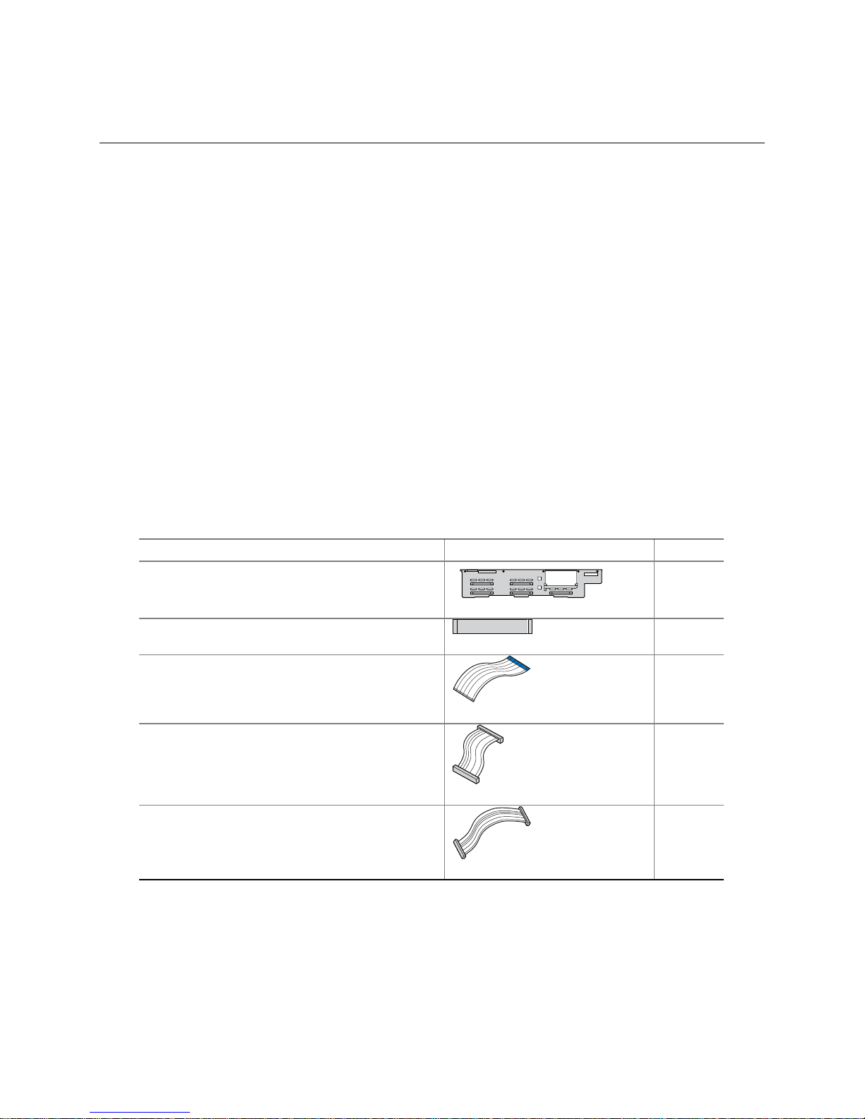
SCSI Backplane Kit
You should have received the following parts if you ordered the SCSI Backplane Kit, order number
A2400SCSIKIT:
SCSI Backplane Parts List
Item Picutre (not to scale) Quantity
SCSI backplane
1
Flex cable
26-pin floppy drive data cable
44-pin CD-ROM drive data cable
50-pin front panel cable
1
1
1
1
continued
About the SATA or SCSI Backplane Kit 1
Page 8
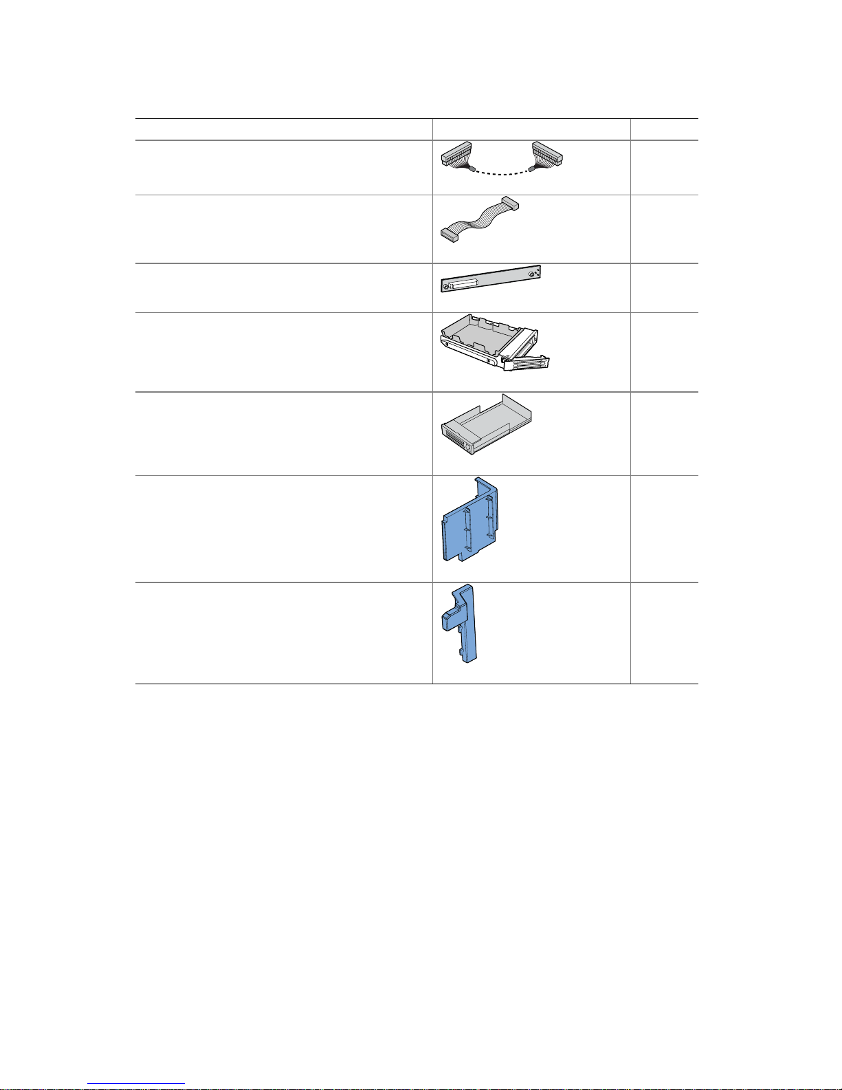
SCSI Backplane Parts List (continued)
Item Picture (not to scale) Quantity
SCSI cable
10-pin fan distribution cable
44-pin CD-ROM drive interposer board with two
screws
Hot-swap driver carrier
Drive bay blank
Large air baffle
1
1
1
5
1
1
Small air baffle
1
2 Intel® Server Chassis SR2400
SCSI and SATA Backplane Installation Instructions
Page 9
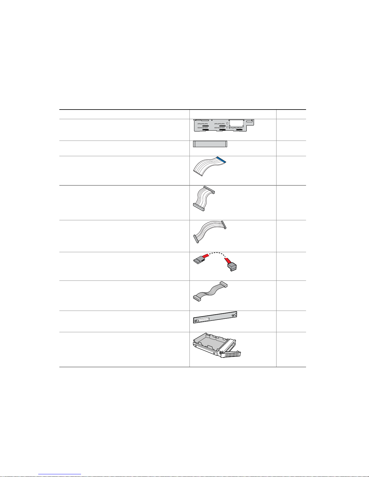
SATA Backplane Kit
You should have received the following parts if you ordered the SATA Backplane Kit, order
number A2400SATAKIT:
SATA Backplane Parts List
Item Picture (not to scale) Quantity
SATA backplane
Flex cable
26-pin floppy drive data cable
44-pin CD-ROM drive data cable
50-pin front panel cable
1
1
1
1
1
SATA cable
10-pin fan distribution cable
CD-ROM drive interposer board with two screws
Hot-swap driver carrier
5
1
1
5
continued
About the SATA or SCSI Backplane Kit 3
Page 10

SATA Backplane Parts List (continued)
Drive bay blank
Large air baffle
Small air baffle
Document Scope and Assumptions
1
1
1
This document provides instructions to guide you through installing the hot-swap SCSI or hot-swap
SATA backplane into the Intel® Server Chassis SR2400.
The server board diagrams in this document are specific to the Intel® Server Board SE7520JR2 and
Intel® Server Board SE7320VP2, although this kit may work with other Intel® Server Boards as
well. For boards other than the Server Board SE7520JR2 or Server Board SE7320VP2, refer to the
documentation that came with your server board to determine compatibility and cable routing.
This document assumes you are installing the backplane kit during an initial integration process,
before your server system is up and running. Because the Quick Start User’s Guide used for the
initial integration is used for several implementations, this instruction guide will ask you to
uninstall selected components that you may have just installed. For the best results, read through
both the Quick Start User’s Guide and this installation guide before beginning your installation.
If you are installing the backplane board into a fully integrated server system that is currently
operational, you will need to uninstall several components. Refer to the Intel® Server Chassis
SR2400 User Guide for instructions on removing and reinstalling components. The User’s Guide is
available at http://support.intel.com/support/motherboards/server/chassis/SR2400/
Tools and Supplies Needed
• Phillips* (cross head) screwdriver (#2 bit)
• Anti-static wrist strap (recommended)
4 Intel® Server Chassis SR2400
SCSI and SATA Backplane Installation Instructions
Page 11

Intel® Server Chassis SR2400 SATA or SCSI
Backplane Installation
Follow Steps in Quick Start User’s Guide
Remove the CD-ROM tray if it is installed in the chassis and follow the instructions in the Intel®
Server Chassis SR2400 Quick Start User’s Guide that came with your server chassis. The Quick
Start User’s Guide will direct you to this guide at the appropriate point during the integration
process.
Release Control Panel
Release lever (see letter “A” in the following figure) and move Control Panel forward about ½ inch
(1 cm).
A
TP00531
Figure 1. Releasing Control Panel
Intel® Server Chassis SR2400 SATA or SCSI Backplane Installation 5
Page 12

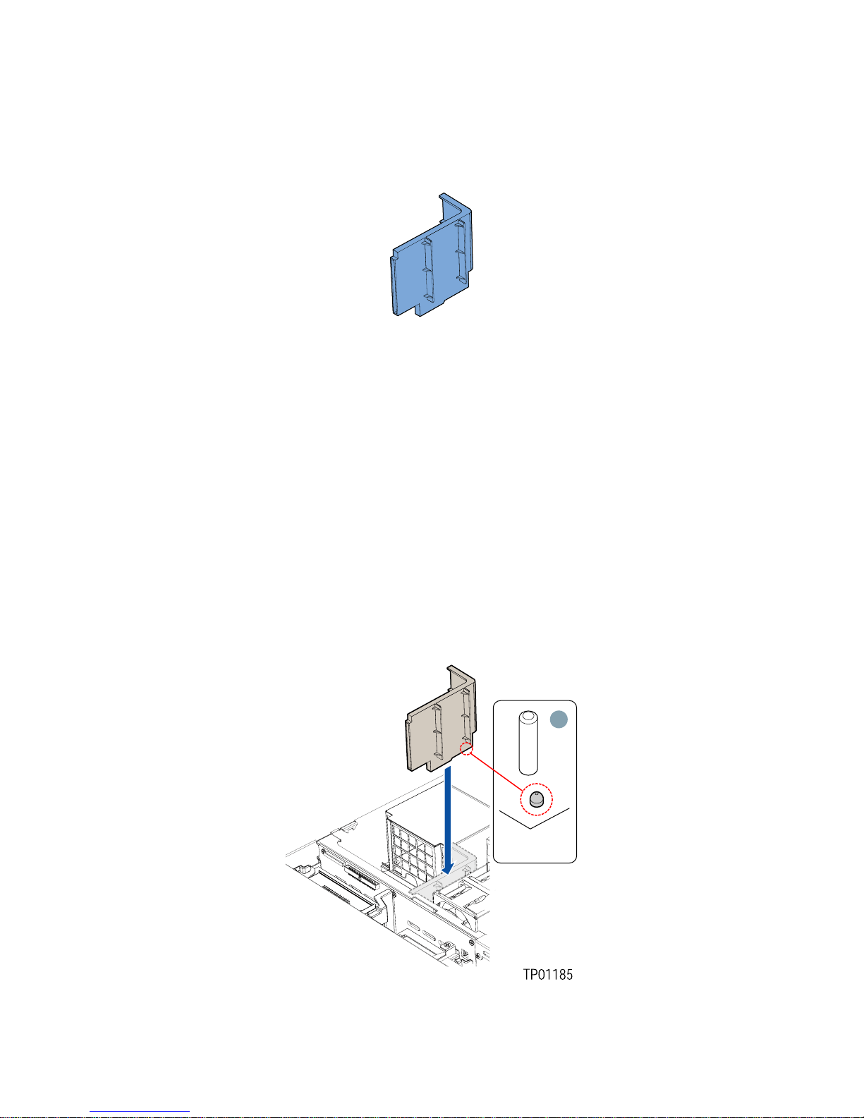
Install Small Air Baffle
The small air baffle shown below must be attached to the drive bay cage for proper system cooling.
Figure 2. Small Air Baffle
1. Lower the small baffle into the chassis behind the drive bay cage area.
2. Insert the two hooks on the baffle (see letter “A” in the figure below) into the matching slots at
the rear of the drive cage area.
3. Push down on the baffle to secure it to the chassis.
6 Intel® Server Chassis SR2400
Figure 3. Installing Small Air Baffle
SCSI and SATA Backplane Installation Instructions
Page 13

Install the SATA or SCSI Backplane
✏ NOTE
Installing a SCSI backplane requires a SCSI connector on the server board. If your server board
does not have a SCSI connector, a SCSI add-in card is required.
1. Lift any power cables cables out of the way.
2. Ensure the USB cable extends from the control panel board and lies inside of the cutout at the
back of the control panel assembly. See letter “A” in the figure below.
3. Push the USB cable toward the fan module on the chassis floor. When the backplane board is
installed, the USB cable will route beneath the backplane board at the right side of the chassis.
4. Use care to avoid pinching any cables. Slide the backplane into the chassis guides at the left
and right sides of the chassis until the pins at the left and right sides of the backplane bracket
are fully inserted into the matching holes in the chassis. See letter “B” for installing the
backplane.
B
Figure 4. Installing SATA or SCSI Backplane
A
TP01074
Intel® Server Chassis SR2400 SATA or SCSI Backplane Installation 7
Page 14

Install the SATA Cable(s)
✏ NOTE
Disregard this step if you installed the SCSI backplane and instead follow the
steps for Install the SCSI Cable.
1. Connect the SATA Cable(s) labeled SATA CH A and SATA CH B to the backplane. See letter
“A” in the figure below to locate the backplane. See letter “B” in the figure to identify the end
of the SATA cable that is attached to the backplane.
2. If you will be using the SATA connections on the server board instead of an an add-in SATA
RAID Controller, connect the 90-degree end of the SATA cable(s) to the corresponding server
board connection(s). The cable connected to SATA CH A should be connected to SATA 0. The
cable connected to SATA CH B should be connected to SATA 1. See letter “C” in the figure
below to identify the end of the SATA cable that is attached to the server board. See your
server board documentation to locate the SATA connection points on the server board.
If you will be using an add-in SATA RAID Controller, you will need to connect SATA CH A
through SATA CH E to the appropriate connectors on the add-in card after you install the addin card. See your add-in card documentation for the appropriate SATA connections.
SATA
CH E
SATA
SATA
SATA
CH C
SATA
CH D
CH B
CH A
A
A
B
SATA1
SATA0
Figure 5. Installing SATA Cables to Server Board
C
TP01078
8 Intel® Server Chassis SR2400
SCSI and SATA Backplane Installation Instructions
Page 15

Install the SCSI Cable
✏ NOTE
Disregard this step if you installed the SATA backplane and instead follow
the steps for Install the SATA Cable.
This step may require a SCSI add-in card if your server board does not have
a SCSI connector. See the documentation included with your SCSI card for
the proper cable connections.
1. Connect the end of the SCSI cable that is labeled “Backplane” to the backplane SCSI
Connector. See letter “A” in the figure below.
2. Connect the end of the SCSI cable that is labeled “Server Board” to the SCSI connection on the
server board if not already connected. See letter “B” in the figure below. See your server board
documentation to locate the SCSI connection point on the server board
B
A
TP01075
Figure 6. Installing SCSI Cable
Intel® Server Chassis SR2400 SATA or SCSI Backplane Installation 9
Page 16
Connect Flex Cable, 50-pin Front Panel Cable, and
Backplane Power Cable
1. Attach the flex cable from the backplane to the server board as shown by letter “A” in the
figure below. Each cable end is labeled “backplane” or “server board” for proper installation.
2. Attach the 2x3 power cable from the power supply to the backplane as shown by letter “B” in
the figure.
3. Connect the 50-pin front panel cable to the backplane as shown by letter “C” in the figure.
Figure 7. Connecting Flex Cable, 50-pin Front Panel Cable, and Backplane Power Cable
10 Intel® Server Chassis SR2400
SCSI and SATA Backplane Installation Instructions
Page 17
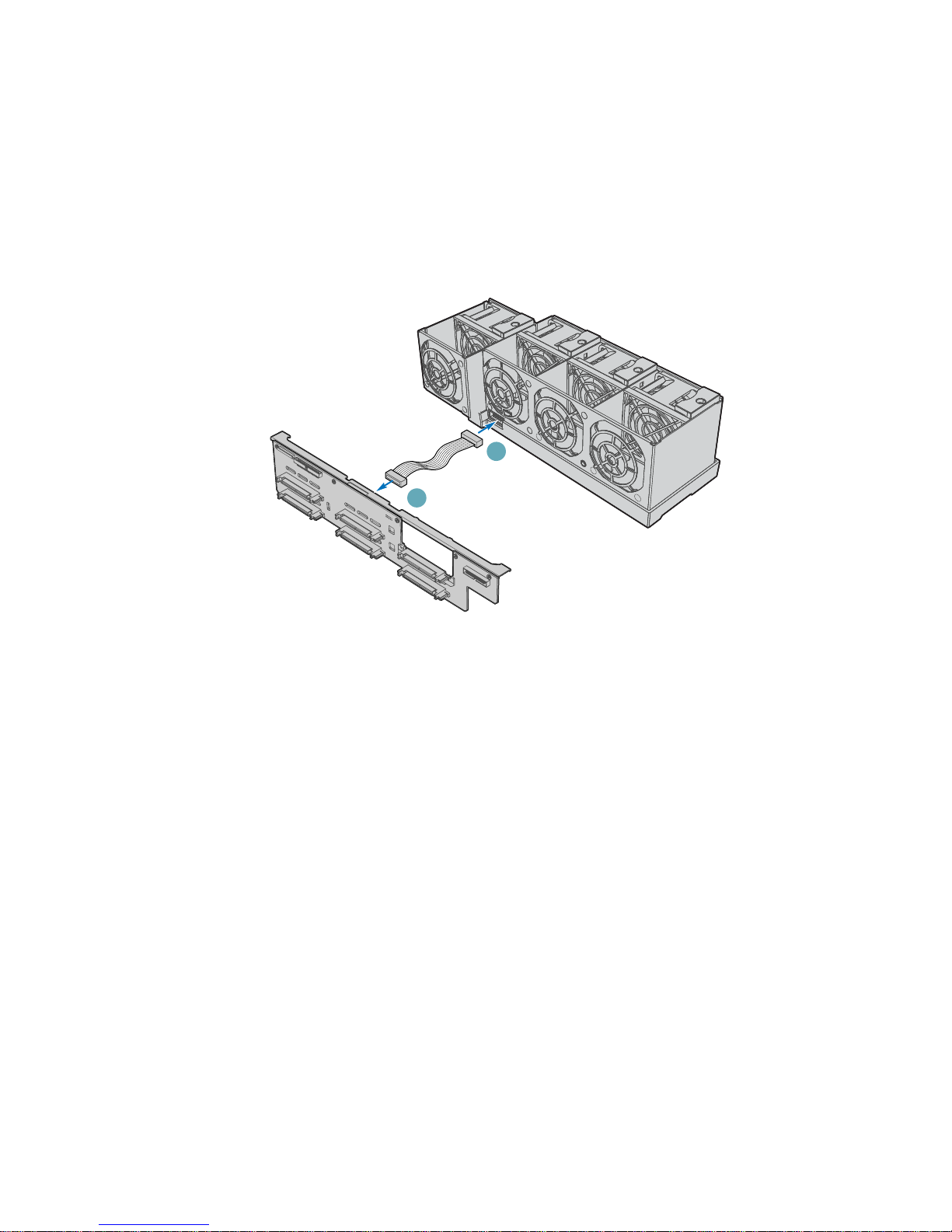
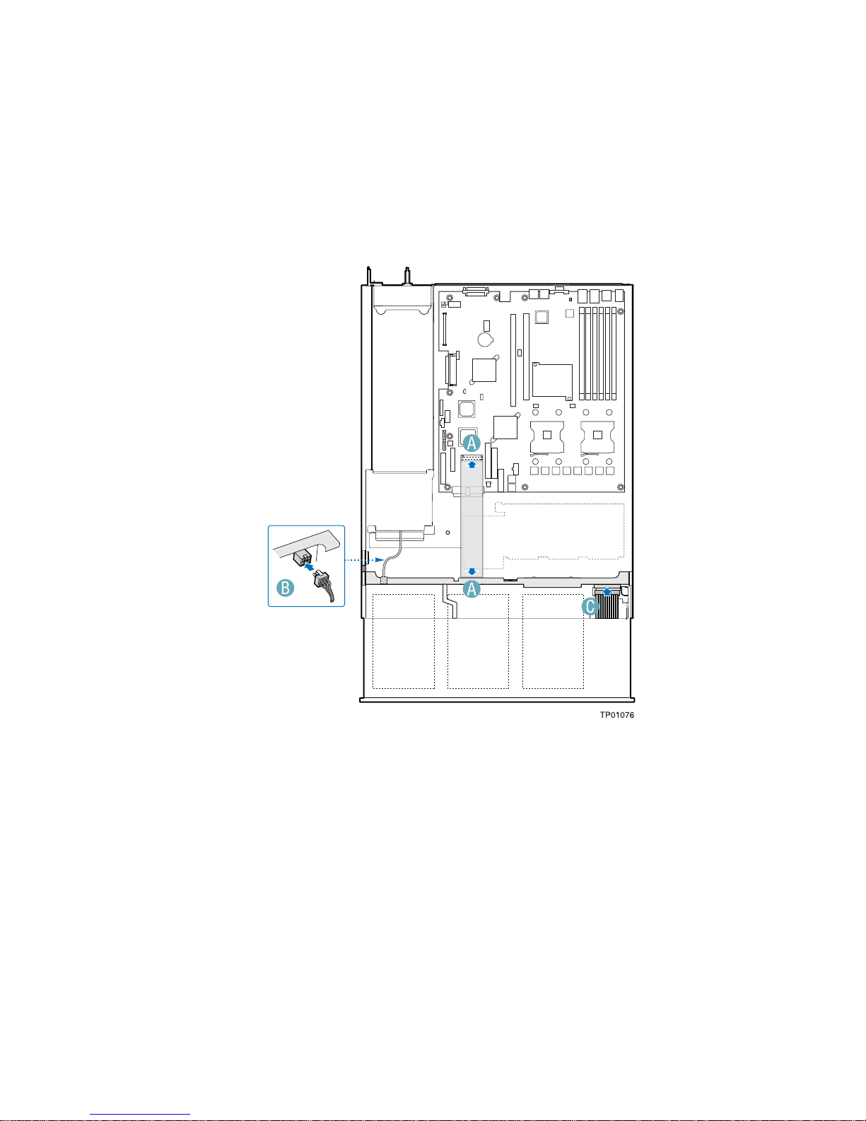
Connect 10-pin Fan Distribution Cable
✏ NOTE
This step must be completed before installing the fan module into the chassis.
1. Attach one end of the 10-pin fan distribution cable to the backplane. See letter “A” in the figure
below.
2. Attach the other end of the fan distribution cable to the fan module. See letter “B” in the figure.
B
A
TP01080
Figure 8. Connecting 10-pin Fan Distribution Cable to Backplane
Intel® Server Chassis SR2400 SATA or SCSI Backplane Installation 11
Page 18

Install Fan Module
✏ NOTE
The fan module is secured to the chassis by matching slots and standoffs.
Make sure module engages in the chassis standoffs.
1. Place the fan module over the chassis standoffs and slide the module to the right until the blue
tab clicks into place. See letter “A” in the figure below.
2. Connect one end of the folded ribbon cable to fan module if not already connected. See letter
“B” in the figure below.
3. Connect other end of the ribbon cable to the server board. See letter “C” in the figure.
B
C
A
TP01081
Figure 9. Installing Fan Module
12 Intel® Server Chassis SR2400
SCSI and SATA Backplane Installation Instructions
Page 19
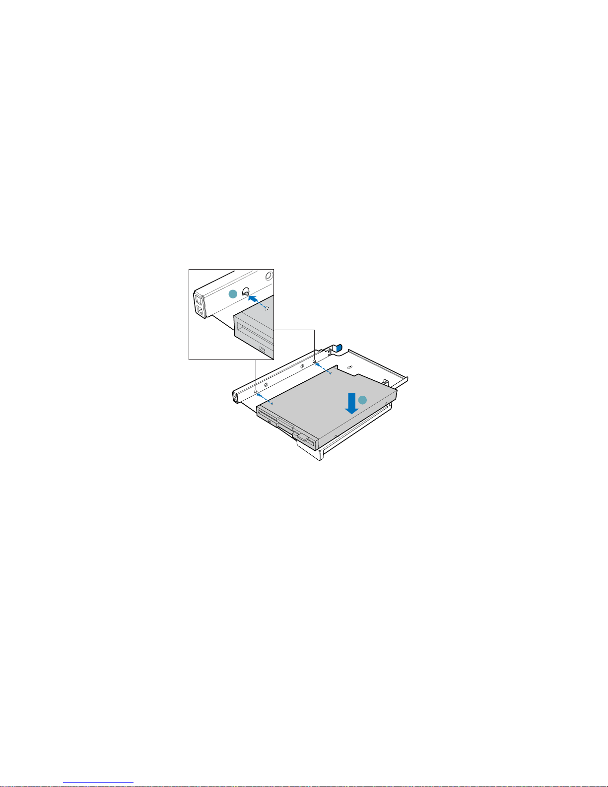
Install Slimline Floppy Drive (optional)
✏ NOTE
The carrier for the slimline floppy drive was sent to you in the hardware kit
that came with your Server Chassis SR2400.
The carrier for the slimline DVD-ROM drive/CD-ROM drive was preinstalled in the slimline drive bay of your Server Chassis SR2400. You will
need to remove it from the chassis before beginning.
1. Align the two holes at the left side of the floppy drive with the two cutouts in the floppy drive
carrier. See letter “A” in the figure below.
2. Lower the right side of the floppy drive into the carrier until it clicks into place.
A
B
TP01082
Figure 10. Installing Slimline Floppy Drive into Carrier
Intel® Server Chassis SR2400 SATA or SCSI Backplane Installation 13
Page 20
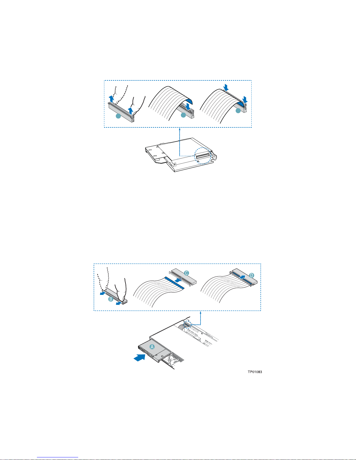
3. Open the connector on the rear of the floppy drive by pulling up on the connector cover. See
letter “A” in the figure below.
4. Insert one end of the 26-pin floppy drive data cable end into the connector.
5. Push down on the connector cover to lock the cable into place.
A
B
C
TP01144
Figure 11. Installing 26-pin Floppy Drive Data Cable to Slimline Floppy Drive
6. Slide the floppy drive assembly into the chassis until it clicks into place. See letter “A” in the
figure below.
7. Open the connector on the backplane by pulling out on the connector cover. See letter “B” in
the figure below.
8. Insert the loose end of the floppy cable into the backplane connector. See letter “C” in the
figure.
9. Push in on the connector cover to lock the cable into place. See letter “D” in the figure.
Figure 12. Installing Slimline Floppy Drive into Chassis
14 Intel® Server Chassis SR2400
SCSI and SATA Backplane Installation Instructions
Page 21

Install Slimline DVD-ROM or CD-ROM Drive (optional)
✏ NOTE
The carrier for the slimline DVD-ROM drive/CD-ROM drive was preinstalled in the slimline drive bay of your Server Chassis SR2400. You will
need to remove it from the chassis before beginning.
1. Align the two holes at left edge of DVD-ROM /CD-ROM drive with the cutouts in drive
carrier. See letter “A” in the figure below.
2. Lower the right side of the DVD-ROM / CD-ROM drive into the carrier until it clicks into
place. See letter “B” in the figure below.
3. Use the two screws indicated in the figure to attach the interpose board to the DVD-ROM / CDROM drive. See letters “C” and “D” in the figure.
4. Attach the 44-pin CD-ROM drive cable to the exposed side / back of the interposer board. See
letter “E” in the figure.
E
D
D
C
B
A
Figure 13. Installing Slimline DVD-ROM / CD-ROM Drive into Carrier
TP01085
Intel® Server Chassis SR2400 SATA or SCSI Backplane Installation 15
Page 22
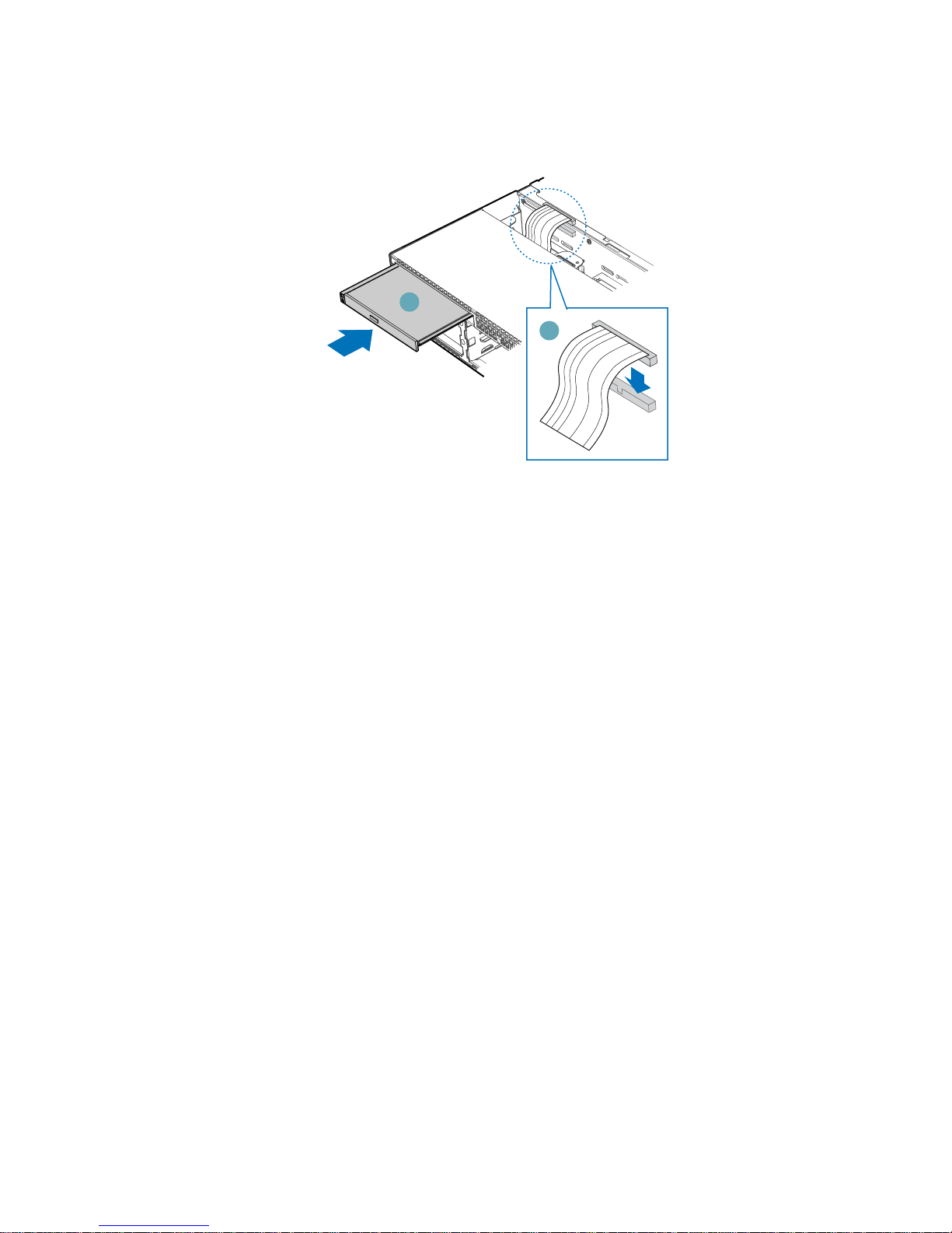
5. Insert the DVD-ROM / CD-ROM drive into the chassis. See letter “A” in the figure below.
6. Connect the loose end of the CD-ROM drive cable to the backplane connector. See letter “B” in
the figure.
A
B
TP01086
Figure 14. Installing Slim Line DVD/CDROM Drive
16 Intel® Server Chassis SR2400
SCSI and SATA Backplane Installation Instructions
Page 23
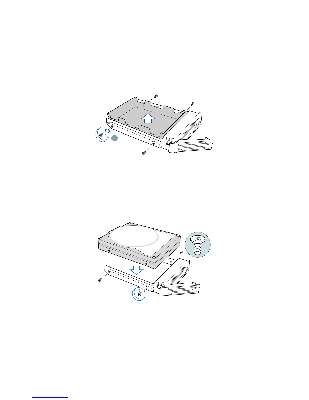
Install Hot-swap Hard Drives
Repeat the steps below for each hard drive to be installed. When installing your drive(s) into the
chassis, the primary drive must be inserted into the lower left drive bay.
1. Set any jumpers and / or switches on the hard drive(s) according to the instructions that came
with your hard drive(s).
2. Remove the four screws that hold the plastic baffle to the drive carrier. See letter “A” in the
figure below. Store the plastic drive baffle for future use.
A
TP01184
Figure 15. Installing Hot-swap Hard Drives into Drive Carrier
3. Position with the drive with circuit side facing down and the connector end of the drive facing
the rear of the drive carrier.
4. Align the holes in the drive to the holes in the drive carrier and attach it to the carrier with the
screws that were attached to the plastic retention device.
TP01140
Figure 16. Installing Hot-swap Hard Drives into Drive Carrier
Intel® Server Chassis SR2400 SATA or SCSI Backplane Installation 17
Page 24
Install Large Baffle
The large baffle has two notches for routing cables between the baffle and the chassis floor. See the
figure below.
Figure 17. Large Baffle
1. Lower the large baffle into the chassis between the power supply and the back side of the
backplane.
2. While setting the baffle into place, route the cables as follows:
Route these cables through both openings under the baffle:
USB
SCSI or SATA cables
Route these cables through the larger opening:
Main power cable
CPU power cable
Power supply signal cable
3. Line up the guide pin on the chassis floor with the matching hole in the baffle. See letter “A” in
the figure below.
4. Push down on the baffle to secure it to the chassis.
18 Intel® Server Chassis SR2400
A
Figure 18. Installing Power Supply Air Baffle
SCSI and SATA Backplane Installation Instructions
Page 25
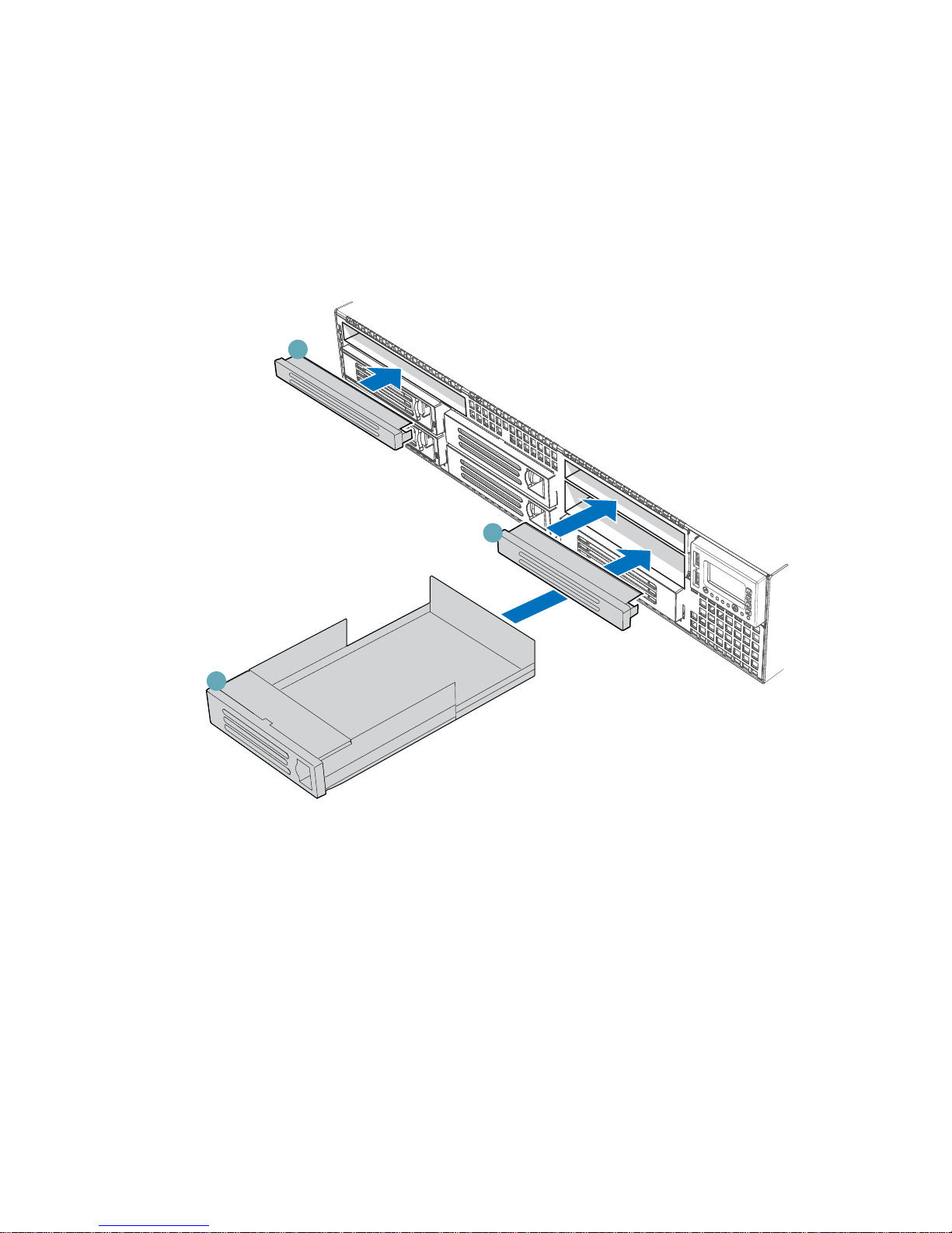
Install Filler Panels (if required)
1. Install the slimline filler panel if you did not install a CD-ROM drive, DVD-ROM drive or
floppy drive. See letter “A” in the figure below.
2. Install the flex bay filler panel. See letter “B” in the figure below.
3. Install the drive bay blank into the sixth drive bay if no drive is installed in this bay. You will
need to order a sixth drive kit (ADRSIXDRIVE or ADRSIXDSATA) in order to install a drive
into this slot. See letter “C” in the following figure.
A
C
Figure 19. Installing Filler Panels
Reposition Front Panel
Push front panel back into chassis until it clicks into place.
B
TP01143
Complete Server System Integration
Return to the Intel® Server Chassis SR2400 Quick Start User’s Guide, continuing with Step 12.
Intel® Server Chassis SR2400 SATA or SCSI Backplane Installation 19
 Loading...