

Page 1

Intel® Local Control Panel for EPSD
Revision 1.0
December, 2012
Enterprise Platforms and Services Division - Marketing
Platforms Based on Intel® Xeon®
Processor E5
4600/2600/2400/1600/1400
Product Families
Technical Product Specification
Intel order number G83726-001
Page 2

Revision History Intel® Local Control Panel for EPSD Platforms TPS
ii
Date
Revision Number
Modifications
November 2012
0.9
Preliminary release.
December 2012
1.0
Updated Firmware Functional Specification.
Revision History
Disclaimers
INFORMATION IN THIS DOCUMENT IS PROVIDED IN CONNECTION WITH INTEL® PRODUCTS. NO LICENSE,
EXPRESS OR IMPLIED, BY ESTOPPEL OR OTHERWISE, TO ANY INTELLECTUAL PROPERTY RIGHTS IS
GRANTED BY THIS DOCUMENT. EXCEPT AS PROVIDED IN INTEL®'S TERMS AND CONDITIONS OF SALE
FOR SUCH PRODUCTS, INTEL® ASSUMES NO LIABILITY WHATSOEVER AND INTEL® DISCLAIMS ANY
EXPRESS OR IMPLIED WARRANTY, RELATING TO SALE AND/OR USE OF INTEL® PRODUCTS INCLUDING
LIABILITY OR WARRANTIES RELATING TO FITNESS FOR A PARTICULAR PURPOSE, MERCHANTABILITY, OR
INFRINGEMENT OF ANY PATENT, COPYRIGHT OR OTHER INTELLECTUAL PROPERTY RIGHT.
A "Mission Critical Application" is any application in which failure of the Intel® Product could result, directly or
indirectly, in personal injury or death. SHOULD YOU PURCHASE OR USE INTEL®'S PRODUCTS FOR ANY SUCH
MISSION CRITICAL APPLICATION, YOU SHALL INDEMNIFY AND HOLD INTEL® AND ITS SUBSIDIARIES,
SUBCONTRACTORS AND AFFILIATES, AND THE DIRECTORS, OFFICERS, AND EMPLOYEES OF EACH,
HARMLESS AGAINST ALL CLAIMS COSTS, DAMAGES, AND EXPENSES AND REASONABLE ATTORNEYS'
FEES ARISING OUT OF, DIRECTLY OR INDIRECTLY, ANY CLAIM OF PRODUCT LIABILITY, PERSONAL
INJURY, OR DEATH ARISING IN ANY WAY OUT OF SUCH MISSION CRITICAL APPLICATION, WHETHER OR
NOT INTEL® OR ITS SUBCONTRACTOR WAS NEGLIGENT IN THE DESIGN, MANUFACTURE, OR WARNING
OF THE INTEL® PRODUCT OR ANY OF ITS PARTS.
Intel® may make changes to specifications and product descriptions at any time, without notice. Designers must not
rely on the absence or characteristics of any features or instructions marked "reserved" or "undefined". Intel®
reserves these for future definition and shall have no responsibility whatsoever for conflicts or incompatibilities arising
from future changes to them. The information here is subject to change without notice. Do not finalize a design with
this information.
The products described in this document may contain design defects or errors known as errata which may cause the
product to deviate from published specifications. Current characterized errata are available on request.
Contact your local Intel® sales office or your distributor to obtain the latest specifications and before placing your
product order.
Copies of documents which have an order number and are referenced in this document, or other Intel® literature, may
be obtained by calling 1-800-548-4725, or go to: http://www.intel.com/design/literature.
Intel order number G83726-001 Revision 1.0
Page 3

Intel® Local Control Panel for EPSD Platforms TPS Table of Contents
iii
Table of Contents
1. Introduction ........................................................................................................................ 1
1.1 Section Outline ....................................................................................................... 1
2. Physical and Electrical Description .................................................................................. 2
2.1 Views and Usage Model ......................................................................................... 2
2.2 System Components and Functions ....................................................................... 4
2.3 Electrical Description .............................................................................................. 5
2.3.1 LCD Controller ....................................................................................................... 5
2.3.2 LCD Display ........................................................................................................... 5
2.3.3 LCD Backlight LEDs ............................................................................................... 6
2.3.4 External Connectors ............................................................................................... 6
2.3.5 Internal Connectors ................................................................................................ 6
3. Firmware Functional Specification .................................................................................... 7
3.1 Overview ................................................................................................................ 7
3.2 LCD Functionality ................................................................................................... 7
3.3 Main Menu ............................................................................................................. 8
3.4 Event Menu ............................................................................................................ 8
3.5 View Menu ............................................................................................................. 9
3.5.1 Firmware Version (FV) ........................................................................................... 9
3.5.2 System Information (SI) ........................................................................................ 10
3.5.3 BMC LAN (BL) Configuration ............................................................................... 10
3.5.4 RMM LAN (RL) Configuration ............................................................................... 10
3.5.5 Power (Pow) ........................................................................................................ 11
3.5.6 Last POST Code (Last PC) .................................................................................. 11
3.6 Configuration (Conf) Menu ................................................................................... 11
3.6.1 BMC LAN (BL) Configuration ............................................................................... 11
3.6.2 RMM LAN (RL) Configuration ............................................................................... 13
3.6.3 Boot Device (BDev) .............................................................................................. 13
3.6.4 Banner (Ban) ........................................................................................................ 13
4. Installing and Removing the Intel® Local Control Panel ................................................ 15
4.1 Installing the Intel® A1U2ULCP Local Control Panel in a 1U server system .......... 15
4.2 Removing the Intel® A1U2ULCP Local Control Panel in a 1U server system ........ 16
4.3 Installing the Intel® A1U2ULCP Local Control Panel in a 2U server system .......... 18
4.4 Removing the Intel® A1U2ULCP Local Control Panel in a 2U server system ........ 20
4.5 Installing the Intel® A4ULCP Local Control Panel in a Pedestal server system ..... 23
4.6 Removing the Intel® A4ULCP Local Control Panel in a Pedestal server system ... 24
4.7 Replacing the Front Panel Board.......................................................................... 26
Appendix A: Installation/Assembly Safety Instructions ....................................................... 27
Revision 1.0 Intel order number G83726-001
Page 4

List of Figures Intel® Local Control Panel for EPSD Platforms TPS
iv
List of Figures
Figure 1: A1U2ULCP for Intel® Rack Server Systems ................................................................. 2
Figure 2: A4ULCP for Intel® Pedestal Server Systems ................................................................ 2
Figure 3: Mounting the A1U2ULCP in an Intel® 2U Server Chassis ............................................. 3
Figure 4: Mounting the A1U2ULCP in an Intel® 1U Server Chassis ............................................. 3
Figure 5: Mounting the A4ULCP in an Intel® Pedestal Server Chassis ........................................ 3
Figure 6: Intel® A1U2ULCP Local Control Panel ......................................................................... 4
Figure 7: Intel® A4ULCP Local Control Panel .............................................................................. 5
Figure 8: Background color during normal scenario .................................................................... 7
Figure 9: Background color during error ...................................................................................... 7
Figure 10: Main Menu ................................................................................................................. 8
Figure 11: Event Menu ................................................................................................................ 8
Figure 12: View Menu ................................................................................................................. 9
Figure 13: System Firmware Versions Menu ............................................................................... 9
Figure 14: System Information menu ........................................................................................ 10
Figure 15: BMC LAN Configuration ........................................................................................... 10
Figure 16: Power Consumed by the System Currently .............................................................. 11
Figure 17: Last BIOS POST Code............................................................................................. 11
Figure 18: Configure Menu Items .............................................................................................. 11
Figure 19: BMC IP Configuration Menu ..................................................................................... 11
Figure 20: BMC IP Source Configuration Menu......................................................................... 11
Figure 21: Screen shot for Configuring IP Address, Subnet Mask, and Gateway ...................... 12
Figure 22: State transition diagram for setting IP Address ......................................................... 13
Figure 23: Boot options configuration menu .............................................................................. 13
Figure 24: Banner configuration menu ................................ ...................................................... 13
Figure 25: Removing the bracket in a 1U server system ........................................................... 15
Figure 26: Installing the Intel® A1U2ULCP Local Control Panel in a 1U server system ............. 16
Figure 27: Removing the Intel® A1U2ULCP Local Control Panel in a 1U server system ........... 17
Figure 28: Installing the bracket in a 1U server system ............................................................. 17
Figure 29: Removing the cage in a 2U server system ............................................................... 18
Figure 30: Removing the bracket in a 2U server system ........................................................... 19
Figure 31: Installing the Intel® A1U2ULCP Local Control Panel in a 2U server system ............. 19
Figure 32: Installing the cage in a 2U server system ................................................................. 20
Figure 33: Removing the cage in a 2U server system ............................................................... 21
Figure 34: Removing the Intel® A1U2ULCP Local Control Panel in a 2U server system ........... 21
Intel order number G83726-001 Revision 1.0
Page 5

Intel® Local Control Panel for EPSD Platforms TPS List of Figures
v
Figure 35: Installing the bracket in a 2U server system ............................................................. 22
Figure 36: Installing the cage in a 2U server system ................................................................. 22
Figure 37: Removing the Front Panel Tray from the Pedestal server system ............................ 23
Figure 38: Installing the Intel® A4ULCP Local Control Panel in a Pedestal server system ......... 24
Figure 39: Removing the Intel® A4ULCP Local Control Panel from a Pedestal server system .. 25
Figure 40: Installing the Front Panel Tray in the Pedestal server system .................................. 25
Figure 41: Removing the Front Panel Board ............................................................................. 26
Figure 42: Removing and Installing the Cap on Front Panel Board ........................................... 26
Figure 43: Installing the New Front Panel Board ....................................................................... 26
Revision 1.0 Intel order number G83726-001
Page 6

List of Figures Intel® Local Control Panel for EPSD Platforms TPS
vi
<This page is intentionally left blank.>
Intel order number G83726-001 Revision 1.0
Page 7

Intel® Local Control Panel for EPSD Platforms TPS Introduction
1
1. Introduction
The Intel® Local Control Panel (Intel® LCP) is an optional accessory that enhances the
manageability of the EPSD Platforms Based on Intel® Xeon® Processor E5
4600/2600/2400/1600/1400 Product Families. The Intel® Local Control Panel provides a way to
locally manage one of these Intel® servers. Combined with the Intel® Baseboard Management
Controller (BMC), the Intel® Local Control Panel allows a user to monitor the health of an Intel®
server platform or configure an Intel® server for remote IPMI management. This allows for
monitoring, configuration, and control of the server, independently from the operating system.
This document describes the architecture, firmware features, and hardware parameters of the
Intel® Local Control Panel.
1.1 Section Outline
This document is divided into the following chapters:
Chapter 1 – Introduction
Chapter 2 – Physical and Electrical Description
Chapter 3 – Firmware Functional Specification
Chapter 4 – Installing and Removing the Intel® Local Control Panel
Appendix A – Installation/Assembly Safety Instructions
Revision 1.0 Intel order number G83726-001
Page 8
Physical and Electrical Description Intel® Local Control Panel for EPSD Platforms TPS
2
2. Physical and Electrical Description
2.1 Views and Usage Model
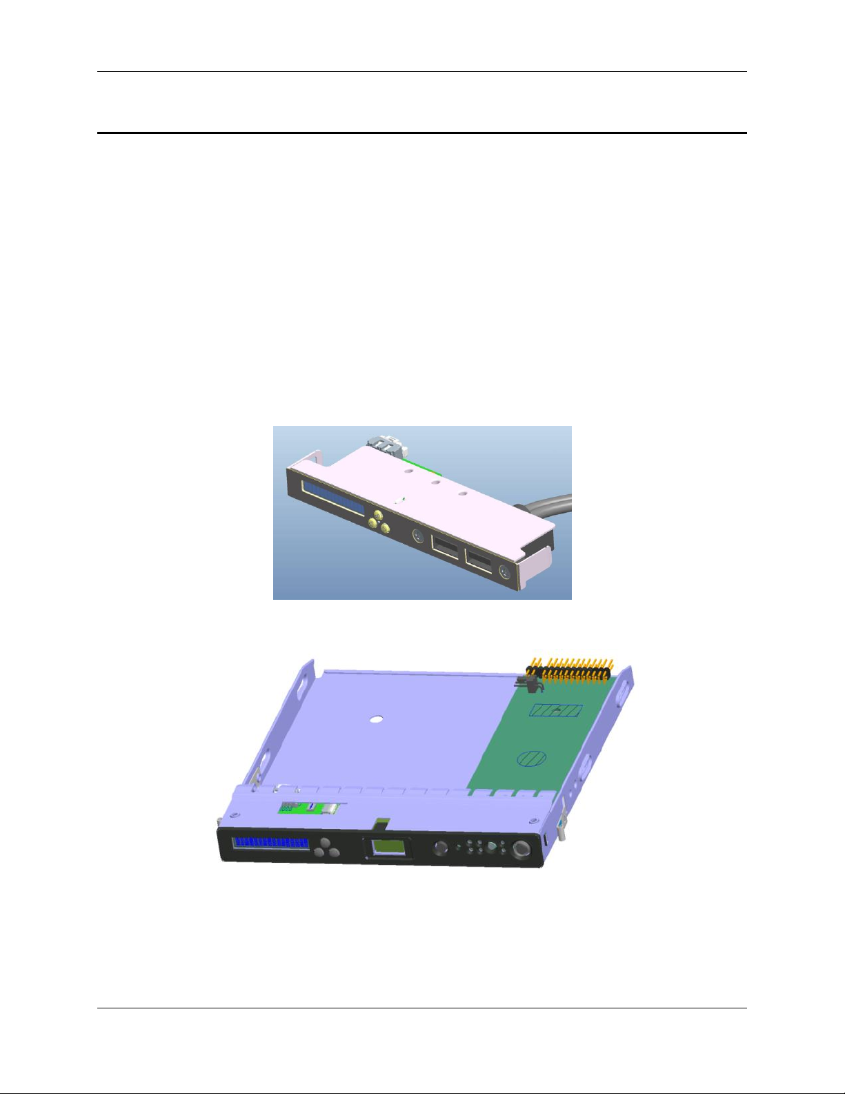
There are two versions of the Intel® Local Control Panel available:
Product Order Code A1U2ULCP is for all Intel® Rack Server Systems R1000BB,
R2000BB, R1000EP, R2000IP, R2000LH2/R2000LT2, R2000SC, R1000GZ/GL, and
R2000GZ/GL Families.
Product Order Code A4ULCP is for all Intel® Pedestal Server Systems P4000CR,
P4000CP, P4000GP, P4000IP, P4000SC, S2400GP/P4000M, S2400SC/P4000M,
S2600CO/P4000M, and S2600CP/P4000M Families.
The LCP is mounted to the front of the chassis using an existing front panel/IO tray for rack
and pedestal. The rack version of the LCP is secured using one screw and supports the two
USB ports. The pedestal version of the LCP snaps into place and has one USB port.
Figure 1: A1U2ULCP for Intel® Rack Server Systems
Figure 2: A4ULCP for Intel® Pedestal Server Systems
Intel order number G83726-001 Revision 1.0
Page 9
Intel® Local Control Panel for EPSD Platforms TPS Physical and Electrical Description
3
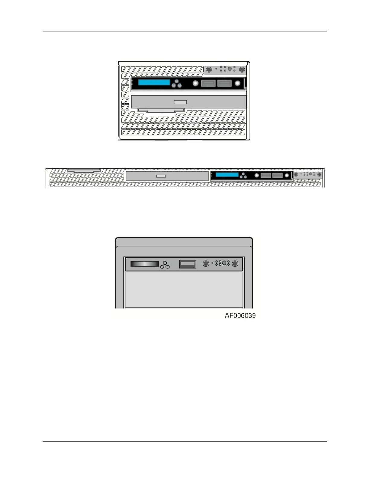
The following figure shows where the LCP should be mounted in an Intel® Rack Server System:
Figure 3: Mounting the A1U2ULCP in an Intel® 2U Server Chassis
Figure 4: Mounting the A1U2ULCP in an Intel® 1U Server Chassis
The following figure shows where the LCP should be mounted in an Intel® Pedestal Server
System:
Figure 5: Mounting the A4ULCP in an Intel® Pedestal Server Chassis
Revision 1.0 Intel order number G83726-001
Page 10

Physical and Electrical Description Intel® Local Control Panel for EPSD Platforms TPS
4
Label
Description
Functionality
A
LCD Display
one line 16 character display
B
Left Control Button
moves the cursor backward one step or one character
C
Enter Button
selects the menu item highlighted by the cursor
D
Right Control Button
moves the cursor forward one step or one character
E
USB 2.0 Port
connect external USB device
F
USB 2.0 Port
connect external USB device
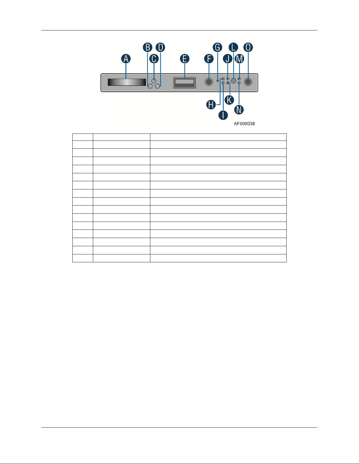
2.2 System Components and Functions
The LCD (Local Control Display) is a one line character display that resides on the LCP. It can
display a maximum of 16 characters at a time. This device also contains three buttons (Left,
Right, and Enter). The user can select the content that needs to be displayed on the LCD
screen by operating these buttons.
The figures below show the Intel® Local Control Panel buttons and configuration:
Figure 6: Intel® A1U2ULCP Local Control Panel
Intel order number G83726-001 Revision 1.0
Page 11
Intel® Local Control Panel for EPSD Platforms TPS Physical and Electrical Description
5
Label
Description
Functionality
A
LCD Display
one line 16 character display
B
Left Control Button
moves the cursor backward one step or one character
C
Enter Button
selects the menu item highlighted by the cursor
D
Right Control Button
moves the cursor forward one step or one character
E
USB 2.0 Port
connect external USB device
F
ID button
with ID LED integrated
G
NMI Button
issue a Non-Maskable Interrupt
H
NIC 2 LED
NIC 2 Activity LED indicator
I
NIC 1 LED
NIC 1 Activity LED indicator
J
NIC 4 LED
NIC 4 Activity LED indicator
K
NIC 3 LED
NIC 3 Activity LED indicator
L
System Reset Button
reset and re-initialize the system
M
HDD Activity LED
hard drive activity LED indicator
N
System Status LED
show the current health of the system
O
Power Button
system Power Button with Power LED
Figure 7: Intel® A4ULCP Local Control Panel
2.3 Electrical Description
The Intel® Local Control Panel is intended to control the display directly from the Baseboard
Management Controller (BMC) with no firmware internal to the LCD module.
2.3.1 LCD Controller
The Intel® Local Control Panel includes a NXP PCF2116CU LCD driver. The PCF2116 supports
24 wide characters; LCD display is only 16 characters.
2.3.2 LCD Display
Number of character: 16 Character x 1 Line
Effective area: 34.8 mm (W) x 5 mm (H)
Character pattern: 5 x 7 dots + cursor
Character size: 1.7 mm (W) x 4.35 mm (H)
Character pitch: 2.1 mm
Revision 1.0 Intel order number G83726-001
Page 12

Physical and Electrical Description Intel® Local Control Panel for EPSD Platforms TPS
6
2.3.3 LCD Backlight LEDs
The LCD has two backlight colors (green and amber).
Under normal conditions the backlight is to be driven green by the BMC. When a problem is
detected with the server, the BMC will deactivate the green backlight and turns-on the amber
backlight. When the baseboard BMC detects the problem has been cleared, the amber
backlight is deactivated to turn-on the green backlight.
2.3.4 External Connectors
The Intel® Local Control Panel has either one or two USB connectors.
2.3.5 Internal Connectors
There is one internal connector for the Intel® A1U2ULCP and the A4ULCP Local Control Panels.
It is a 7-pin header that provides power and control information to and from the server
baseboard. A 7-pin cable connects the LCP to the server baseboard.
For the A4ULCP Local Control Panel, there is a second cable for the USB connector that will
connect to the server baseboard
Intel order number G83726-001 Revision 1.0
Page 13

Intel® Local Control Panel for EPSD Platforms TPS Firmware Functional Specification
7
<Banner>
<Error>
3. Firmware Functional Specification
3.1 Overview
LCD (Local Control Display) is a one line character display that resides on the front panel of a
chassis. It can display maximum of 16 characters at a time. However, a few special characters
such as {, }, `, ~, and ^ are not available in the current LCD controller supported set of
characters. So these characters are mapped to their nearest lookalike characters of LCD. This
device also contains three buttons (Left, Right, and Enter). The user can select the contents that
need to be displayed on the LCD screen by operating these buttons. The BMC firmware drives
the display of this LCD panel based on the user’s selection. These three buttons are connected
to the GPIO pins of the BMC and the LCD controller is connected to the BMC using I2C bus.
3.2 LCD Functionality
The LCD device provides the following features:
Displays a banner when the system is healthy. The default banner is the Server Name.
One exception is when a user sets a custom string using the command, “Write LCD
Custom String (0xB3)”, the set custom string will become the banner automatically, until
the user changes the banner option in the banner configuration menu.
Displays active error messages when the system is not healthy.
Provides the ability to quickly see asset information on system without having to open
the chassis.
Provides basic server management configuration.
The LCD display is menu driven. Based on the user’s selection, respective menu items are
displayed. As soon as the system gets power, the LCD panel shall try to display the fault
detected in the system. If more than one fault exists, it displays the latest high severity fault
(event). If there are no faults, a banner is displayed. Default banner is Server Name. Server
Name is the value specified as the product name in the product FRU information in the main
board BMC FRU. User can set any of the parameters given under the banner configuration
menu as a banner string, which will be discussed later in this section. When the system’s status
is degraded, the corresponding active event will be displayed in place of the banner. During an
error, background color will be light amber in color. The LCD panel returns to a light green or
blue background when there are no longer any degraded, non-fatal, or fatal events active. The
LCD panel shall operate in lock-step with the system status LED. For example, if the system is
operating normally and an event occurs that results in the system status LED to blink green,
then the LCD shall display the degraded event that triggered the systems status LED to blink.
Figure 8: Background color during normal scenario
Figure 9: Background color during error
Revision 1.0 Intel order number G83726-001
Page 14

Firmware Functional Specification Intel® Local Control Panel for EPSD Platforms TPS
8
|Evt|View|Conf
|||<Active Err Evt>
On pressing Enter button when the screen shows banner or error message, the Main Menu is
displayed. The Main Menu contains Evt, View, and Conf items. Based on the user’s selection
in the Main Menu, respective sub-menu items will be displayed. At any point of time, if there is
no user intervention for more than 10 minutes, latest high severity event in the system is
displayed (if one exists or a banner is displayed if the system is healthy).
The following sections discuss about the individual menu items. It is assumed that no active
event exists in the system during the LCD display in the following figures. That is the reason
why the background color of LCD in the following examples is light green. If any event (fatal or
non-fatal) occurs that degrades the system’s health, the color of the LCD background turns into
light amber. Even though all the contents (full text) are shown in the example screen shots in
the following sections, by default, only the first 16 characters are displayed when a particular
menu item is selected. The remaining text can be viewed by using Right or Left buttons.
3.3 Main Menu
On pressing Enter button, when Banner/Error screen is displayed, the following main menu is
displayed. Using Left and Right buttons, the cursor can be moved under any one of the
following four menu items.
Figure 10: Main Menu
If the user selects menu item, then the LCD displays the previous screen, that is,
Banner/Error string. Selecting the menu item means, moving the cursor under that item using
Left or Right buttons and pressing the Enter button subsequently. In all the following sections
(or for any screen shot), if the user presses Enter button, when the cursor is under the symbol
, it displays the previous screen. Selecting any of the menu items; Evt, View, or Conf, leads
the display to their corresponding screen shots and the details are given in the following
sections.
3.4 Event Menu
If the Evt item is selected in the main menu, the LCD displays the following screen shown in the
figure.
Figure 11: Event Menu
This screen is used to traverse the current active error event messages in the system. The
latest high severity event is displayed in place of the banner if one exists. If more than one
critical or degraded event exists in the system, this screen can be used to traverse all of them.
However, at any given time, the LCD retains and displays a maximum of the 20 latest high
severity events. When a higher or a same level of severity event happens as the 21st event,
then the oldest low severity event will be discarded. It is assumed that a system will not have
more than 20 active (asserted) critical events at any given time. The menu items, and are
used to traverse among these event messages. Selection of the menu item , displays the
previous event and the item , displays the next event in human readable format. By default, it
Intel order number G83726-001 Revision 1.0
Page 15

Intel® Local Control Panel for EPSD Platforms TPS Firmware Functional Specification
9
|FV|SI|BL|RL|Pow|LPC
|BIOS|BMC|ME|FRUSDR
displays the latest high severity event if one exists or System Health OK message if there are
no active (asserted) errors in the system currently. If there are more than two active events in
the system, then they are displayed in the descending order of their severity when menu item,
is selected. If two events have the same severity, then the latest one will be displayed first.
Each error event scrolls once automatically so that the entire message can be read without
pressing either the Left or Right buttons. To make the event message scroll again from the
start, Right button has to be pressed when the cursor is under the event message. Pressing
any other button will stop scrolling and the corresponding action for that button press will be
taken. Switching between scrolling and freezing the screen and vice-versa is not supported due
to the limitation of LCD controller.
3.5 View Menu
The following screen is displayed when View item is selected in the main menu.
Figure 12: View Menu
The meaning of the menu items of the above screen are as follows:
FV - Firmware Versions
SI - System Information
BL - BMC LAN Information
RL - RMM LAN Information
Pow - Current Power usage
LPC - Last POST Code
Based on the user’s selection, details of the specific item will be displayed. The following sub
sections explain the above menu items in detail.
3.5.1 Firmware Version (FV)
Selecting FV item in the View menu displays the list of firmware items available in the system
as shown in the following figure. Selecting any item in the following screen displays its version
string or version number:
Figure 13: System Firmware Versions Menu
Revision 1.0 Intel order number G83726-001
Page 16

Firmware Functional Specification Intel® Local Control Panel for EPSD Platforms TPS
10
|SN|SM|AT|SGUID|CSTR
|IPSource|IPAddr|SMask|GWay
3.5.2 System Information (SI)
Selecting SI item in the View menu displays the following screen.
Figure 14: System Information menu
The menu items for the above screen are described below:
SN (System Name): Value specified in the product name in the product FRU information
in the main board BMC FRU.
SM (Server Model): Value specified in the product part number in the product FRU
information in the main board BMC FRU.
AT (Asset Tag): Value specified in the product asset tag in the product FRU information
in the main board BMC FRU.
SGUID (System GUID): System UUID stored by BIOS.
CSTR (Customizable String): Custom string placed by the OEM\end user.
Selecting any item in the above screen displays its value.
3.5.3 BMC LAN (BL) Configuration
Selecting BL item in the View menu displays the following screen.
Figure 15: BMC LAN Configuration
The items displayed on selection of the above menu options are as follows:
IPSource: Source of the BMC IP address will be displayed. Either Static or DHCP will
be displayed on selecting this item.
IPAddr: Displays the BMC IP address.
SMask: Displays the subnet mask of the BMC.
GWay: Displays default Gateway of the BMC.
3.5.4 RMM LAN (RL) Configuration
Selecting RL item in the View menu displays the same screen as above, but selection of
individual items displays the values of RMM (Remote Management Module) rather than that of
BMC.
Intel order number G83726-001 Revision 1.0
Page 17

Intel® Local Control Panel for EPSD Platforms TPS Firmware Functional Specification
11
|xxxx W
|XX
|BL|RL|BDev|Ban
|IPSource|IPAddr|SMask|GWay
|Static|DHCP
3.5.5 Power (Pow)
Selecting Pow item in the View menu displays the amount of AC power drawn by the system in
Watts.
Figure 16: Power Consumed by the System Currently
3.5.6 Last POST Code (Last PC)
Selecting LPC item in the View menu displays the last BIOS POST (Power On Self Test) code
in hexadecimal. If the Last POST Code details are not available with the BMC, then No BIOS
POST CODE message is displayed. The last POST code is displayed only when the POST is in
progress. Once the POST is complete, then it displays POST Complete message.
Figure 17: Last BIOS POST Code
3.6 Configuration (Conf) Menu
If the user selects Conf item in the main menu, then the following options will be displayed
to configure:
Figure 18: Configure Menu Items
The following sub-sections will explain individual items of the configuration menu.
3.6.1 BMC LAN (BL) Configuration
If the user selects BL item in the Conf menu, then the following options will be displayed:
Figure 19: BMC IP Configuration Menu
Selecting IPSource in the above menu leads to the following screen. Based on the user’s
selection in the following menu, BMC IP source will be set either as Static or DHCP.
If the user selects DHCP or the existing IP source is DHCP, then the other menu items, that is,
IP Address, Subnetmask, and Gateway are not configurable. If the user selects Static or the
existing setting is static for IP source, then the user is allowed to change the other menu items
Revision 1.0 Intel order number G83726-001
Figure 20: BMC IP Source Configuration Menu
Page 18

Firmware Functional Specification Intel® Local Control Panel for EPSD Platforms TPS
12
|000.000.000.000|Set
and the following screen is displayed on selecting any of IPAddr, SMask, and GWay items. The
selected item will be set with the configured value once Set is selected in the following figure.
Figure 21: Screen shot for Configuring IP Address, Subnet Mask, and Gateway
By default, the cursor will be under the symbol, and the IP address is displayed as
000.000.000.000. A Right button will take the cursor to the first position (first 0) of the IP
address. When the cursor is under the second menu item, the functionality of Left, Right and
Enter buttons is different from the previous screens. The second token consists of twelve 0’s
separated by ‘.’ character in IP address format. The behaviors of these buttons are as follows
when the cursor is under this item.
1. Left and Right buttons inside the second menu item traverses among the 0 positions
within the same item.
2. If the cursor is under last position inside the second menu item, then a Right button
will move the cursor to next item, that is, Set.
3. If the cursor is under first position inside the second menu item, then a Left button
moves the cursor to the previous item, that is .
4. First Enter button at any “0” position makes that position to be selected to increment
or decrement the value at that position. The values allowed are between and
including 0 and 9.
5. Any further Left or Right buttons will decrement or increment the value at that
position.
6. Second Enter button at that position makes the cursor to be ready for moving left or
right. Any further left or right movement shifts the cursor to the previous or next
position respectively.
7. So, the Enter button is used to select a position at the first time and to leave the
position at the second time.
The following state transition diagram explains the above steps pictorially, while setting an IP
address using the LCD device. After entering an IP address, the user has to select Set item to
set the entered IP address to the corresponding parameter (IP Address, Subnet Mask, or
Gateway).
Intel order number G83726-001 Revision 1.0
Page 19

Intel® Local Control Panel for EPSD Platforms TPS Firmware Functional Specification
13
Left/
Right
Enter
Enter
Left
Left
Right
Right
Pos:
x
Pos:
x+1
Pos:
Increment/
Decrement
|DVD|HD|NetBoot|EFI
|SN|SM|Err|BIP|RIP|Pow|LPC|CStr
x-1
Figure 22: State transition diagram for setting IP Address
3.6.2 RMM LAN (RL) Configuration
Same screen shots and the same description as mentioned in BMC LAN (BL) Configuration are
applicable for RMM LAN configuration menu also. However, the values configured will be
assigned to LAN parameters of RMM module rather than that of BMC.
3.6.3 Boot Device (BDev)
If the user selects BDev in the Conf menu, then the following options will be displayed. The
selected item will be set as the next boot option.
Figure 23: Boot options configuration menu
3.6.4 Banner (Ban)
When the user selects Ban in the Conf menu, the following options will be displayed. The
selected item will be set as the banner and the same will be displayed from the next banner
screen onwards.
Figure 24: Banner configuration menu
Each of the menu items are explained below:
SN (System Name): Displays the value specified in the product name in the product
FRU information in the main board BMC FRU. System Name is the default banner.
Revision 1.0 Intel order number G83726-001
Page 20

Firmware Functional Specification Intel® Local Control Panel for EPSD Platforms TPS
14
SM (System Model): Displays the value specified in the product part number in the
product FRU information in the main board BMC FRU.
Err (Error): Displays the last active system event. The last active event may be
degraded, non-critical or critical only. It shall not display an informational message. If the
system is healthy then it displays System Health Ok.
BIP (BMC IP): Displays BMC’s IP address as banner.
RIP (RMM IP): Displays RMM’s IP address as banner.
Pow (Power): Displays the current system power consumption in Watts as a banner.
LPC (Last POST Code): Displays last BIOS POST code as the banner.
CStr (Customizable String): Displays a customizable text string. The custom text string
is modifiable through BIOS setup or a utility by using the Intel® General Application (Net
Function: 0x30) command 0xB3 (Write LCD Custom String).
Intel order number G83726-001 Revision 1.0
Page 21

Intel® Local Control Panel for EPSD Platforms TPS Installing and Removing the Intel® Local Control Panel
15
4. Installing and Removing the Intel
This section will describe how to install and remove the Intel® Local Control Panel in your server
system
4.1 Installing the Intel
1. Disconnect the front video cable and the front USB cable from the server board
(see letter A)
2. Remove the two screws (see letter B).
3. Slide out the bracket from server chassis together with cables (see letter C).
4. Remove the two screws and slide out the front USB connecter from the bracket
(see letter D).
®
A1U2ULCP Local Control Panel in a 1U server system
®
Local Control Panel
Figure 25: Removing the bracket in a 1U server system
5. Install the front USB connecter to the Intel® Local Control Panel bracket and secure the
two screws (see letter E).
6. Connect the LCP cable to the LCP board and install the Intel® Local Control Panel
bracket into server chassis together with cables (see letter F).
7. Secure the two screws (see letter G).
8. Connect the Intel® Local Control Panel cable and the front USB cable to the server board
(see letter H).
Revision 1.0 Intel order number G83726-001
Page 22

Installing and Removing the Intel® Local Control Panel Intel® Local Control Panel for EPSD Platforms TPS
16
Figure 26: Installing the Intel® A1U2ULCP Local Control Panel in a 1U server system
4.2 Removing the Intel
®
A1U2ULCP Local Control Panel in a 1U server
system
1. Disconnect the Intel® Local Control Panel cable and the front USB cable from the server
board (see letter A).
2. Remove the two screws (see letter B).
3. Slide out the Intel® Local Control Panel from server chassis together with cables
(see letter C).
4. Remove the two screws and slide out the front USB connecter from the bracket
(see letter D).
Intel order number G83726-001 Revision 1.0
Page 23

Intel® Local Control Panel for EPSD Platforms TPS Installing and Removing the Intel® Local Control Panel
17
Figure 27: Removing the Intel® A1U2ULCP Local Control Panel in a 1U server system
5. Install the front USB connecter to the bracket and secure the two screws (see letter E).
6. Install the bracket together with cables (see letter F).
7. Secure the two screws (see letter G).
8. Connect the front video cable and the front USB cable to the server board (see letter H).
Figure 28: Installing the bracket in a 1U server system
Revision 1.0 Intel order number G83726-001
Page 24

Installing and Removing the Intel® Local Control Panel Intel® Local Control Panel for EPSD Platforms TPS
18
4.3 Installing the Intel
®
A1U2ULCP Local Control Panel in a 2U server system
1. Remove the system top cover.
2. For 2U system with 2.5” hard drive configuration, remove the stiffener first. Please refer
to the Intel® Server System Service Guide for detailed instructions.
3. For 2U system with 2.5” hard drive configuration, remove the three screws to release the
hard drive cage (see letter A). For 2U system with 3.5” hard drive configuration, remove
the six screws to release the hard drive cage. Please refer to the Intel® Server System
Service Guide for detailed instructions.
4. Disconnect the front video cable and the front USB cable from the server board
(see letter B).
5. Slide out the cage from server chassis together with cables (see letter C).
Figure 29: Removing the cage in a 2U server system
6. Remove the two screws to release the bracket (see letter D).
7. Slide out the bracket from cage together with cables (see letter E).
8. Remove the two screws and slide out the front USB connecter from the bracket
(see letter F).
Intel order number G83726-001 Revision 1.0
Page 25

Intel® Local Control Panel for EPSD Platforms TPS Installing and Removing the Intel® Local Control Panel
19
Figure 30: Removing the bracket in a 2U server system
9. Install the front USB connecter to the Intel® Local Control Panel bracket and secure the
two screws (see letter G).
10. Connect the LCP cable to the LCP board and install the Intel® Local Control Panel
bracket into server chassis together with cables (see letter H).
11. Secure the two screws (see letter I).
Figure 31: Installing the Intel® A1U2ULCP Local Control Panel in a 2U server system
12. Install the cage into server chassis (see letter J). For 2U system with 3.5” hard drive
configuration, install the clip to server chassis.
13. For 2U system with 2.5” hard drive configuration, secure the three screws (see letter K).
For 2U system with 3.5” hard drive configuration, secure the six screws. Please refer to
the Intel® Server System Service Guide for detailed instructions.
14. Connect the Intel® Local Control Panel cable, the front USB cable and the front panel
cable to the server board (see letter L).
Revision 1.0 Intel order number G83726-001
Page 26

Installing and Removing the Intel® Local Control Panel Intel® Local Control Panel for EPSD Platforms TPS
20
Figure 32: Installing the cage in a 2U server system
15. For 2U system with 2.5” hard drive configuration, install the stiffener. Please refer to the
Intel® Server System Service Guide for detailed instructions.
4.4 Removing the Intel
®
A1U2ULCP Local Control Panel in a 2U server
system
1. Remove the system top cover.
2. For 2U system with 2.5” hard drive configuration, remove the stiffener first. Please refer
to the Intel® Server System Service Guide for detailed instructions.
3. Disconnect the Intel® Local Control Panel cable, the front USB cable and the front panel
cable from the server board (see letter A).
4. For 2U system with 2.5” hard drive configuration, remove the three screws to release the
hard drive cage (see letter B). For 2U system with 3.5” hard drive configuration, remove
the six screws to release the hard drive cage. Please refer to the Intel® Server System
Service Guide for detailed instructions.
5. Slide out the cage from server chassis together with cables (see letter C).
Intel order number G83726-001 Revision 1.0
Page 27

Intel® Local Control Panel for EPSD Platforms TPS Installing and Removing the Intel® Local Control Panel
21
Figure 33: Removing the cage in a 2U server system
6. Remove the two screws (see letter D).
7. Slide out the Intel® Local Control Panel from server chassis together with cables
(see letter E).
8. Remove the two screws and slide out the front USB connecter from the bracket
(see letter F).
Figure 34: Removing the Intel® A1U2ULCP Local Control Panel in a 2U server system
9. Install the front USB connecter to the bracket and secure the two screws (see letter G).
10. Install the bracket together with cables (see letter H).
11. Secure the two screws (see letter I).
Revision 1.0 Intel order number G83726-001
Page 28

Installing and Removing the Intel® Local Control Panel Intel® Local Control Panel for EPSD Platforms TPS
22
Figure 35: Installing the bracket in a 2U server system
12. Install the cage into server chassis (see letter J).
13. For 2U system with 2.5” hard drive configuration, secure the three screws (see letter K).
For 2U system with 3.5” hard drive configuration, secure the six screws. Please refer to
the Service Guide of your Intel® Server System for detailed instructions.
14. Connect the front video cable, the front USB cable and the front panel cable to the
server board (see letter L).
Figure 36: Installing the cage in a 2U server system
15. Install the stiffener. Please refer to the Intel® Server System Service Guide for detailed
instructions.
Intel order number G83726-001 Revision 1.0
Page 29

Intel® Local Control Panel for EPSD Platforms TPS Installing and Removing the Intel® Local Control Panel
23
4.5 Installing the Intel
®
A4ULCP Local Control Panel in a Pedestal server
system
1. Remove the front panel cable and USB cable from motherboard (see letter A).
2. Slide the front panel tray out from the chassis (see letter B and C).
3. Refer to Replacing the Front Panel Board to remove front panel board from the front
panel tray, and then install into the LCP.
Figure 37: Removing the Front Panel Tray from the Pedestal server system
4. Insert the LCP into the chassis (see letter H).
5. Connect all cables on related connectors on the motherboard (see letter I).
Revision 1.0 Intel order number G83726-001
Page 30

Installing and Removing the Intel® Local Control Panel Intel® Local Control Panel for EPSD Platforms TPS
24
Figure 38: Installing the Intel® A4ULCP Local Control Panel in a Pedestal server system
4.6 Removing the Intel
®
A4ULCP Local Control Panel in a Pedestal server
system
1. Disconnect all cables from the motherboard (see letter A).
2. Slide the LCP out from the chassis (see letter B and C).
3. Refer to Replacing the Front Panel Board to remove the front panel board from the LCD
module, and then install into the front panel tray.
Intel order number G83726-001 Revision 1.0
Page 31

Intel® Local Control Panel for EPSD Platforms TPS Installing and Removing the Intel® Local Control Panel
25
Figure 39: Removing the Intel® A4ULCP Local Control Panel from a Pedestal server system
4. Insert the front panel tray into the chassis (see letter H).
5. Connect all cables of the related connectors on the motherboard (see letter I).
Figure 40: Installing the Front Panel Tray in the Pedestal server system
Revision 1.0 Intel order number G83726-001
Page 32

Installing and Removing the Intel® Local Control Panel Intel® Local Control Panel for EPSD Platforms TPS
26
4.7 Replacing the Front Panel Board
1. Observe the safety and Electro Static Discharge (ESD) precautions at the beginning of
this document.
2. Remove the screw (see Letter A) securing the front panel board and remove the front
panel board (see Letter B).
Figure 41: Removing the Front Panel Board
3. Remove the cap on the front panel board power button and install the new cap on the
new front panel board power button.
Figure 42: Removing and Installing the Cap on Front Panel Board
4. Attach the new front panel board in the front panel tray or LCP (see letter A) and secure
the new front panel board with the screw (see letter B).
Figure 43: Installing the New Front Panel Board
Intel order number G83726-001 Revision 1.0
Page 33

Intel® Local Control Panel for EPSD Platforms TPS Appendix A: Installation/Assembly Safety Instructions
27
Appendix A: Installation/Assembly Safety Instructions
Observe the following safety guidelines:
Do not operate your computer system with any cover(s) (such as computer covers,
bezels, filler brackets, and front-panel inserts) removed.
To help avoid damaging your computer, be sure the voltage selection switch on the
power supply is set to match the alternating current (AC) power available at your
location.
To help avoid possible damage to the server board, wait five seconds after turning off
the system before removing a component from the server board or disconnecting a
peripheral device from the computer.
To help prevent electric shock, plug the computer and peripheral power cables into
properly grounded power sources. These cables are equipped with three-prong plugs to
ensure proper grounding. Do not use adapter plugs or remove the grounding prong from
a cable. If you must use an extension cable, use a three-wire cable with properly
grounded plugs.
To help protect your computer system from sudden, transient increases and decreases
in electrical power, use a surge suppressor, line conditioner, or uninterruptible power
supply.
Be sure nothing rests on your computer system's cables and that the cables are not
located where they can be stepped on or tripped over.
Do not spill food or liquids on your computer. If the computer gets wet, refer the
documentation that came with it.
Do not push any objects into the openings of your computer. Doing so can cause fire or
electric shock by shorting out interior components.
Keep your computer away from radiators and heat sources. Also, do not block cooling
vents. Avoid placing loose papers underneath your computer; do not place your
computer in a closed-in wall unit or on a rug.
When working on the inside of your computer:
Do not attempt to service the computer system yourself, except as explained in this
guide and elsewhere in Intel® documentation. Always follow installation and service
instructions closely.
Turn off your computer and any peripherals.
Disconnect your computer and peripherals from their power sources. Also disconnect
any telephone or telecommunications lines from the computer.
Doing so reduces the potential for personal injury or shock.
Revision 1.0 Intel order number G83726-001
Page 34

Appendix A: Installation/Assembly Safety Instructions Intel® Local Control Panel for EPSD Platforms TPS
28
Additional safety guidelines:
When you disconnect a cable, pull the connector or the strain-relief loop, not the cable
itself. Some cables have a connector with locking tabs; if you are disconnecting this type
of cable, press in on the locking tabs before disconnecting the cable. As you pull
connectors apart, keep them evenly aligned to avoid bending any connector pins. Also,
before you connect a cable, make sure both connectors are correctly oriented and
aligned.
Handle components and cards with care. Do not touch the components or contacts on a
card. Hold a card by its edges or by its metal mounting bracket. Hold a component such
as a microprocessor chip by its edges, not by its pins.
Protecting against Electro Static Discharge (ESD):
Static electricity can harm delicate components inside your computer. To prevent static
damage, discharge static electricity from your body before you touch any of your
computer's electronic components, such as the microprocessor. You can do so by
touching an unpainted metal surface, such as the metal around the card-slot openings at
the back of the computer.
As you continue to work inside the computer, periodically touch an unpainted metal
surface to remove any static charge your body may have accumulated. In addition to the
preceding precautions, you can also take the following steps to prevent damage from
Electro Static Discharge (ESD).
When unpacking a static-sensitive component from its shipping carton, do not remove
the component from the antistatic packing material until you are ready to install the
component in your computer. Just before unwrapping the antistatic packaging, be sure
to discharge static electricity from your body.
When transporting a sensitive component, first place it in an antistatic container or
packaging.
Handle all sensitive components in a static-safe area. If possible, use antistatic floor
pads and workbench pads.
Intel order number G83726-001 Revision 1.0
 Loading...