

Intek M-760 PLUS Owner's Manual
OWNER'S MANUAL
MANUALE DI ISTRUZIONI
MULTI STANDARD PROGRAMMABLE
27 MHz CB MOBILE TRANSCEIVER
M-760 PLUS
Declaration of Conformity
With the present declaration, we certify that the following products :
INTEK M-760 PLUS
comply with all the technical regulations applicable to the above mentioned products
in accordance with the EC Directives 73/23/EEC, 89/336/EEC and 99/5/EC.
Type of product : CB Transceiver
Details of applied standards : EN 300 433, EN 300 135-2
EN 301 489-1, EN 301 489-13
EN 60065
Manufacturer : INTEK S.R.L.
Via G. Marconi, 16
20090 Segrate, Italy
Tel. 39-02-26950451 / Fax. 39-02-26952185
E-mail : intek.com@intek-com.it
Notified Body : EMCCert Dr. Rasek
Boelwiese 5, 91320 Ebermannstadt
Germany
Identification Number : 0678
Contact Reference : Armando Zanni
Tel. 39-02-26950451 / Fax. 39-02-26952185
E-mail : intek.com@intek-com.it
Segrate, 31/07/2007 dr. Vittorio Zanetti
(General Manager)
DECLARATION OF CONFORMITY
EC Certificate of Conformity
(to EC Directive 99/5-89/336-93/68-73/23)
NOTICE !
It is recommended to carefully read this owner’s manual before using the product. This will also help the user to
prevent using the radio in violation of the regulations valid in the country where the product is used, as well as to
avoid any possible interferences with other services.
0678
CH
RoHS
2002/95/EC

car mounting bracket accessories (hardware, knobs, etc.)
microphone bracket
owner’s manual
Index - Introduction - Content of the package
- 1 -
Index . . . . . . . . . . . . . . . . . . . . . . . . . . . . . . . . . . . . . . . . . . . . . . . . . . . . . . . . . . . . . . . . . . . . . . . . . . . . . .1
Introduction / Content of the package . . . . . . . . . . . . . . . . . . . . . . . . . . . . . . . . . . . . . . . . . . . . . . . . . . 1
Controls, Indicators and operation . . . . . . . . . . . . . . . . . . . . . . . . . . . . . . . . . . . . . . . . . . . . . . . . . . 2 - 8
Installation . . . . . . . . . . . . . . . . . . . . . . . . . . . . . . . . . . . . . . . . . . . . . . . . . . . . . . . . . . . . . . . . . . . . . . . . 9
Frequency bands table - User Information . . . . . . . . . . . . . . . . . . . . . . . . . . . . . . . . . . . . . . . . . . . . . 10
Frequency band selection / programming . . . . . . . . . . . . . . . . . . . . . . . . . . . . . . . . . . . . . . . . . . . . . . 11
Table of restrictions on the use of CB transceivers . . . . . . . . . . . . . . . . . . . . . . . . . . . . . . . . . . . . . . 11
Specifications . . . . . . . . . . . . . . . . . . . . . . . . . . . . . . . . . . . . . . . . . . . . . . . . . . . . . . . . . . . . . . . . . . . . . 12
Table of restrictions on the use of CB transceivers . . . . . . . . . . . . . . . . . . . . . . . . . . . . . . . . . . . . . . . I
VCO Diagram / ESP Compander Diagram . . . . . . . . . . . . . . . . . . . . . . . . . . . . . . . . . . . . . . . . . . . . . . . II
PCB - Main Board & Front Board . . . . . . . . . . . . . . . . . . . . . . . . . . . . . . . . . . . . . . . . . . . . . . . . . . III - IV
Diagram . . . . . . . . . . . . . . . . . . . . . . . . . . . . . . . . . . . . . . . . . . . . . . . . . . . . . . . . . . . . . . . . . . . . . . .V- VI
Block Diagram . . . . . . . . . . . . . . . . . . . . . . . . . . . . . . . . . . . . . . . . . . . . . . . . . . . . . . . . . . . . . . . . VII-VIII
English
NOTICE !
Before using this transceiver, please check that the radio has been programmed on the frequency bands,
specifications and operating modes allowed by the regulations valid in the country where the product is used. If
not, please proceed to modify the frequency band programming, as it is described in this owner’s manual. This
transceiver is factory pre-programmed on the CE European frequency band (CEPT 40CH FM 4W).
Congratulations!
Congratulations for selecting and purchasing an INTEK quality product. This transceiver includes a number of advanced
functions and systems, therefore it is definitely necessary to carefully read this owner’s manual before using the radio.
With a correct use of the product in accordance with the operating method described in this manual, the product will offer
a trouble free use for many years. INTEK is constantly engaged to develop and provide quality products meeting the
customers requirements, however any suggestion or comments on this product that might help us to improve quality are
warmly welcome. INTEK M-760 PLUS is a CB transceiver using advanced hardware and software design, it includes
a special multi-standard programmable circuit, which allows to program the specifications of the radio (frequency
bands, operating modes, transmitter power) in compliance with the regulations valid in the various European
countries. Therefore this product can be used in any country of the European Community. The radio is delivered
factory pre-programmed on the CE European frequency band (CEPT 40CH FM 4W).
Content of the package
Please check that all the following items are contained in the packaging :
main unit (transceiver)
DC power cord with fuse holder and fuse
condenser microphone
car mounting bracket
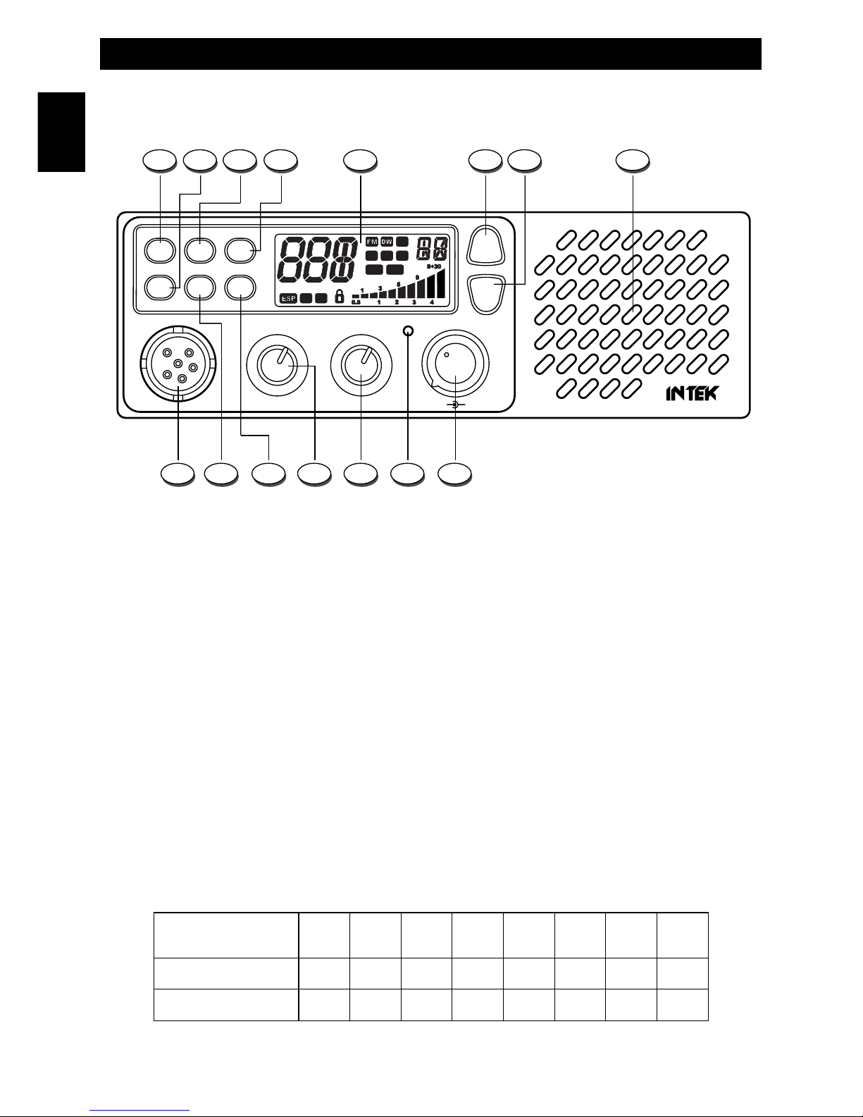
Controls, Indicators and operation
- 2 -
Front panel
1. AM/FM and UK/CE Key
AM/FM SELECTOR
Shortly press the AM/FM Key (1) to select the AM or FM operating mode in both RX and TX. The AM/FM operating
mode selection is possible only if it is allowed the programmed frequency band, otherwise the selection is not possible.
UK/CE SELECTOR
If the UK (United Kingdom) frequency band has been programmed, press this key for about 2 seconds to select the
UK channels/frequencies or the CE channels/frequencies. The channel display will show "U" for the UK
channels/frequencies and "C" for the CE channels/frequencies.
2. RB / LCR Key
Shortly press the RB (2) Key to enable the Roger Beep function (automatic beep tone at the end of each transmission).
Pressing this key for about 1.5 seconds, the last used channel will be automatically recalled.
3. EMG / DW Key
EMG (Emergency Channels)
This key allows quick access to one of the two pre-programmed emergency channels (CH9 or CH19). Each time this key is
pressed, radio will select CH9, then CH19, then again the normal operating channel. When one of the emergency channels
is selected, the EMG (L) icon will appear on the LCD display. The operating mode (AM or FM) for the emergency channels
is factory pre-programmed as per the following table.
English
OFF/VOLUME AS/SQUELCH
TX
AM/FM EMG ESP
RB SCAN ANL
DW
PALCR
UK/CE
M-760 PLUS
UP
DN
MIC/G RF/G
1 42 3 5
915 11121314 10
6 87
C E
LO
SC
AM
ANL EMG
RB
FREQUENCY BAND
ID CODE
CH-9
CH-19
E1
AM
AM
I2
AM
AM
DE
AM
AM
D2
AM
AM
EU
AM
AM
CE
FM
FM
UK
FM
FM
PL
AM
AM
Controls, Indicators and operation
- 3 -
English
DW (Dual Watch)
The DW (Dual Watch) function allows automatic alternate monitoring of two programmable channels. Select the first
channel to be monitored using the UP (6) and DN (7) keys or the channel selection keys on the microphone (21, 23). To
enable the DW function, press the DW (3) key for about 2 seconds, until the DW (F) icon appears and blinks on the LCD
display. Now select the second channel to monitor using the UP (6) and DN (7) keys or the channel selection keys on
the microphone (21, 23). Press again the DW (3) key for about 2 seconds. The DW function is now enabled and the
LCD display will alternately show the channel number of the two programmed channels. The DW (F) icon will be lighted
on the LCD display. Monitoring stops if a signal is detected on one of the two channels, in order to let the user listen to
the incoming signal and will start again when no signal is detected on that channel. It is possible to transmit on that
channel, by simply pressing the PTT (20) key. If there is no transmission within 5 seconds, monitoring will re-start. To exit
the DW mode, shortly press the PTT (20) button.
4. ESP (Electronic Speech Processor) Key
The ESP (Electronic Speech Processor) is a unique feature available in some INTEK two-way CB radios. ESP means
Electronic Speech Processor, in other words electronic modulation processor. This audio processor is microprocessor
controlled and it is also called COMPANDER (Compressor-Expander). It works as a modulation compressor in transmit
mode and as a modulation expander in receive m ode. The ESP allows to obtain a stronger, clear and clean audio signal
and it is a great help in noisy areas and in case of weak signals or in long distance communication. The efficiency of
ESP is even greater when both stations use this device. The 2nd generation ESP allows to enable only the TX
compressor, only the RX expander or both systems.
To enable or disable the ESP functions, press the ESP key (4), as follows :
1) Press the key once to enable the TX modulation compressor. The ESP C (P) icon will appear on the LCD.
2) Press the key again to enable the RX modulation expander. The ESP E (P) icon will appear on the LCD.
3) Press the key again to enable both the TX modulation compressor and the RX modulation expander.
The ESP C E (P) icon will appear on the LCD.
4) Press the key once again to disable all systems.
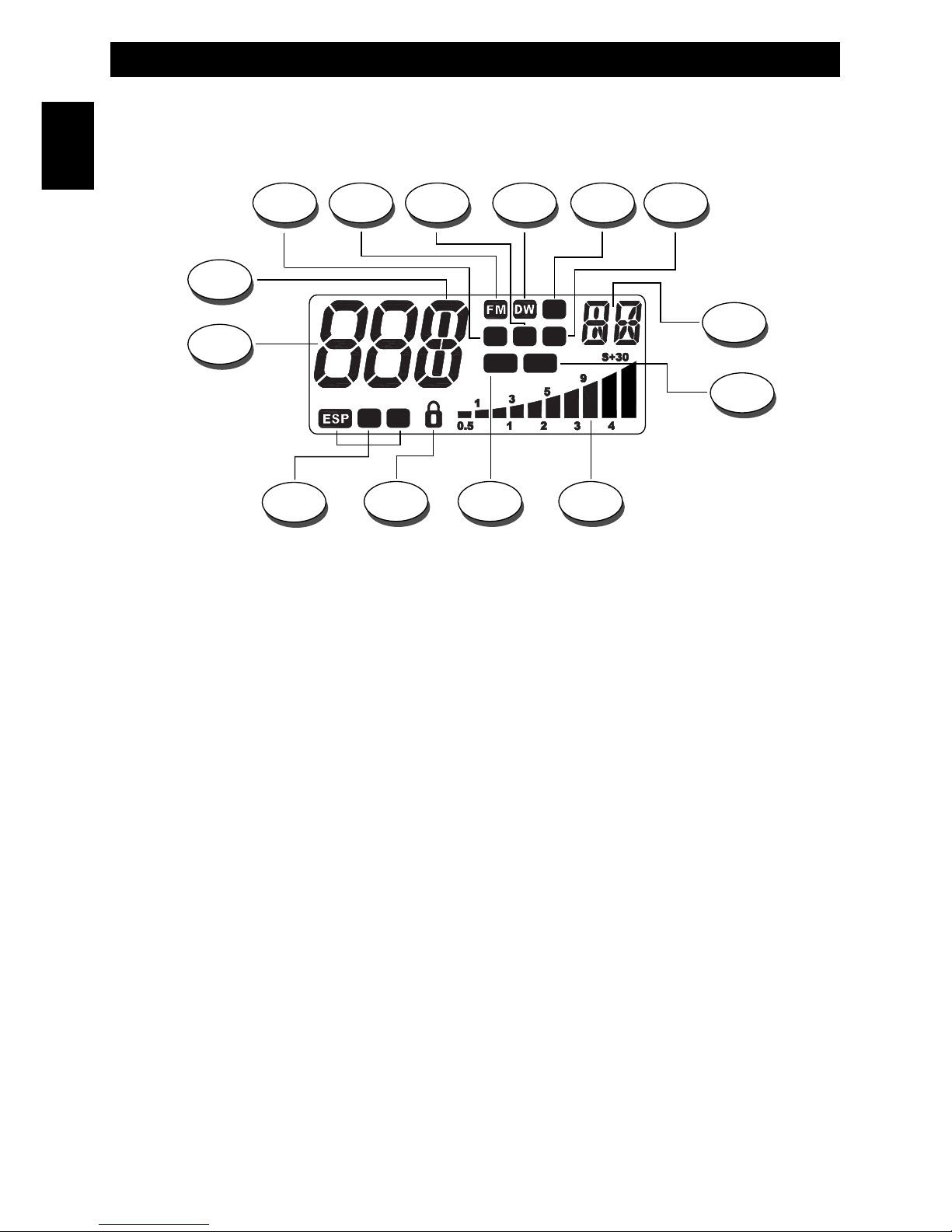
5. LCD Display
The LCD display has a large size and an orange colour backlighting system, for best readability. The LCD display
shows all the enabled functions as well as several other information programmable by the user, such as the
programmed band ID code. It also includes a digital 10-bar S/RF Meter (M) to monitor the strength/power of the
received and transmitted signals.
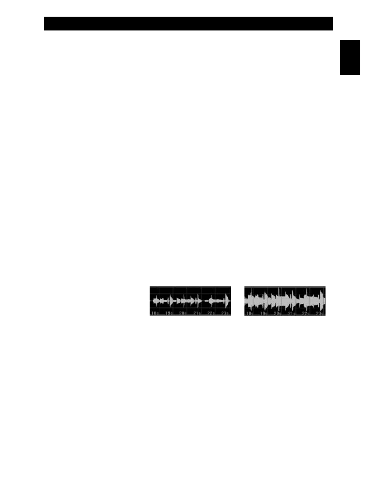
Modulation without ESP Modulation with ESP
100%
0%
100%
ESP performance
of the modulation
in RX and TX modes
Controls, Indicators and operation
- 4 -
A. Channel Number
Channel number indication (from 01 to 80, according to the selected frequency band).
If the UK (United Kingdom) frequency band has been programmed, the channel display will show "U" for the UK
channels/frequencies and "C" for the CE channels/frequencies, followed by the channel number.
B. Alpha-numeric Indication
Channel alpha-numeric indication.
C. AM Icon
The AM icon is lighted when radio has been set to the AM (Amplitude Modulation) operating mode.
D. FM Icon
The FM icon is lighted when radio has been set to the FM (Frequency Modulation) operating mode.
E. SC Icon
The SCAN icon is lighted when the SCAN function has been enabled, in order to automatically search busy channels or
busy memory channels.
F. DW Icon
The DW icon is lighted when the DW (DUAL WATCH) function has been enabled, in order to automatically monitor two
different channels.
G. LO Icon
The LO icon is lighted when the transmitter is in the LOW POWER (1W) mode.
H. RB Icon
The RB icon is lighted when the Roger Beep function is enabled.
English
LCD Display
C D FE G H
B
M
I
L
O N
A
P
C E
LO
SC
AM
ANL EMG
RB

Controls, Indicators and operation
- 5 -
English
I. Frequency Band ID Code
It indicates the programmed frequency band ID code (i.e. DE, UK, CE, etc.).
L. EMG Icon
The EMG icon is lighted when one of the pre-programmed Emergency Channels has been selected.
M. S/RF Digital Meter
A digital 10-bar S/RF METER indicates the strength of the received signal (from S0 to S9+30) in the receive mode and
the transmitter RF output power (0 to 4W) in the transmit mode.
N. ANL Icon
The ANL icon is lighted when the ANL (Automatic Noise Limiter) function is enabled.
O. LOCK Icon
The LOCK icon is lighted when the LOCK function has been enabled.
P. ESP C E Icon
The ESP C E icon is lighted when the ESP (Electronic SPEECH PROCESSOR) function has been enabled.
6. UP (Up) Key
This key allows to select the operating channel upward. By keeping this key pressed, the quick channel selection mode
will be enabled.
7. DN (Down) Key
This key allows to select the operating channel downward. By keeping this key pressed, the quick channel selection
mode will be enabled.
8. Built-in Speaker
Built-in front speaker.
9. MIC GAIN / RF GAIN Dual Control
MIC GAIN CONTROL
This radio uses a high quality condenser microphone. The microphone gain is adjustable with the MIC GAIN (center)
control knob. Turn the knob clockwise to increase the microphone gain.
RF GAIN CONTROL
This radio has a high sensitivity and selectivity receiver circuit design. The receiver RF gain is adjustable with the
RF GAIN (outer) control knob.
Turn the knob clockwise to increase the receiver RF gain, in case of weak signals or long distance communication.
Turn the knob counterclockwise to reduce the receiver RF gain, in case of very strong signals.
10. TX Indicator
This red colour LED indicator lights up when radio is in transmit mode.

Controls, Indicators and operation
- 6 -
English
11. AS/SQUELCH Control
SQUELCH CONTROL (SQUELCH manual adjustment)
The SQUELCH control allows to silent the receiver by cutting the background noise, when no signals are received. Turn
the knob clockwise until the background noise is cut. Turn the knob counter clockwise (SQUELCH opening) in order to
listen to the weakest signals.
AS CONTROL (SQUELCH fixed setting)
The AS function allows to automatically silent the receiver, avoding the SQUELCH manual adjustment. A fixed
SQUELCH threshold is factory pre-set. To enable the fixed SQUELCH function, turn the knob fully counter clockwise to
the AS position, until a click noise is heard.
12. OFF/VOLUME control
This knob switches the radio ON and OFF and it adjusts the volume control. If no signals are being received on the
operating channel, it is suggested to open the SQUELCH and adjust the volume to the desired level while listening to the
background noise.
13. ANL/PA key
ANL (Automatic Noise Limiter) FUNCTION
Shortly press the ANL/PA (13) key to enable the ANL (Automatic Noise Limiter) function, in order to reduce
electric or electromagnetic noise or interference on the used channel. The ANL (N) icon is lighted to
confirm that the ANL function is enabled. Press again the ANL /PA(13) key to disable the function.
PA (Public Address) CONTROL
The radio includes the PA (Public Address) function, in order to spread audio messages through an external speaker. To
use the PA function, connect an external speaker (optional) to the PA jack (17) located on the rear side of the radio.
Press the ANL/PA (13) key for about 1.5 seconds. The PA (A) icon appears on the LCD display. Now it is possible to
press the PTT (20) key and speak into the microphone to spread your message through the external speaker. Adjust the
microphone gain with the RF/G (9) knob to the desired level.
14. SCAN Key
By pressing the SCAN key, the SCAN (automatic scanning of busy channels) function is enabled. To enable the SCAN function,
first turn the AS/SQUELCH (11) control clockwise, until the background noise is cut. Then press the SCAN (14) key, radio will
automatically start scanning all channels continuously and the SC (E) icon will appear on the LCD. Auto-scan stops if a signal is
detected on a channel, in order to let the user listen to the incoming signal and will start again when no signal is detected on that
channel. If the PTT (20) Key is pressed within 5 seconds, radio will remain on that channel, otherwise scanning will start again.
Auto-scan may be also re-started at any time by pressing again the SCAN (14) key. To exit the SCAN mode, shortly press the
PTT (20) button.
15. MICROPHONE Connector
Connect the supplied condenser microphone to this connector, locking it through the ring nut.
Controls, Indicators and operation
- 7 -
English
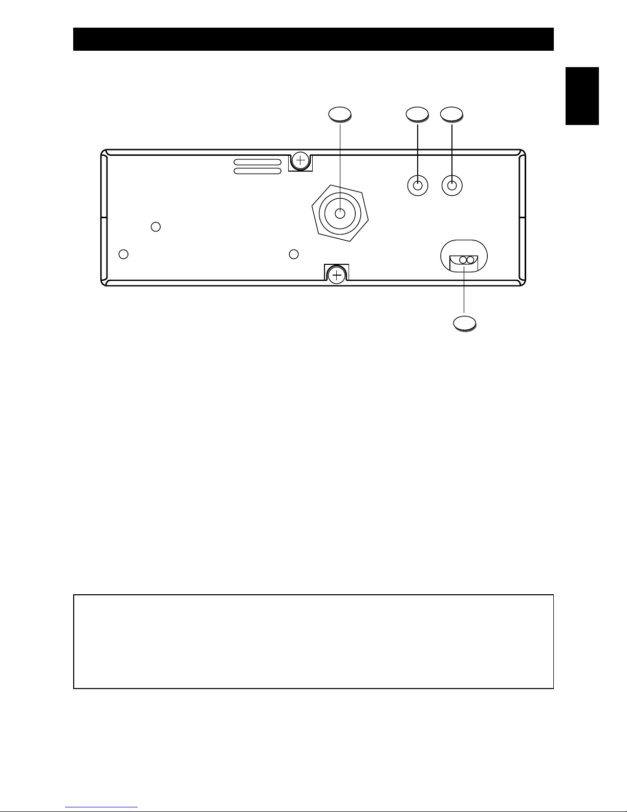
Rear Panel
16. ANTENNA Connector
Antenna connector. Refer to the section INSTALLATION OF THE ANTENNA.
17. PA Jack
If the PA function has to be used, connect to the external speaker (optional) to this jack. Refer to item no. 13.
18. EXT (External Speaker) Jack
This jack is for connecting an external speaker (optional).
19. 13.2VDC POWER CORD
13.2VDC power cord input.
ANTENNA
EXTPA
POWER
13.2V DC
16 17 18
19
WARNING !
Do never try to open the cabinet of the radio. No user serviceable parts are inside the cabinet. Tampering or
modifying the circuit of the radio or its original factory adjustment may cause damage to the product, may change
the electrical specifications and will void the warranty. If service is required, please refer only to a qualified and
authorized service center.
Controls, Indicators and operation
- 8 -
English
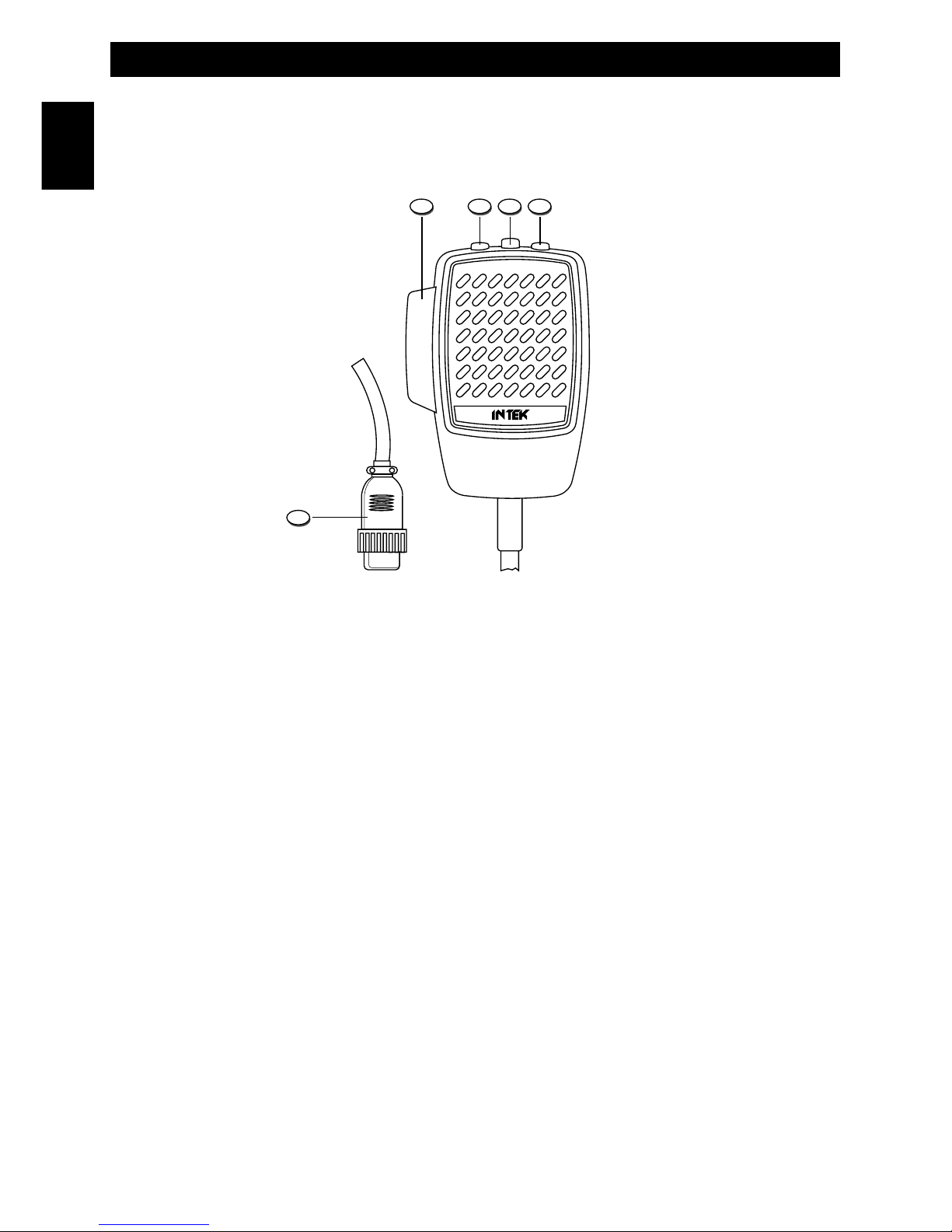
Microphone
20. PTT (Push-to-Talk) Key
Transmitter key. Press the PTT (20) key to transmit and release it to return to the receive mode.
21. UP (Channel Selector) Key
Each time this key is pressed, the channel number will move upward by one channel.
22. LOCK (Keypad Lock) Key
The LOCK function is enabled when pressing this key, in order lock the keypad and prevent entering unwanted
commands. When the LOCK function is enabled, the LOCK (O) icon appears on the LCD display.
23. DOWN (Channel Selector) Key
Each time this key is pressed, the channel number will move downward by one channel.
24. MICROPHONE Plug
6-pole microphone plug with locking ring nut, to be connected to the microphone connector (15) located on the front side
of the radio.
222120
24
23

Installation
- 9 -
English
Installation
Before installing the main unit in the vehicle, check and select the most convenient location, in order that the radio will be
easy to reach and comfortable to operate, without disturbing or interfering with the vehicle drive. Use the supplied
bracket and hardware to install the radio. The bracket screws must be well tightened in order not to become loosen with
the vehicle vibrations. The car mounting bracket can be installed over or below the radio and the radio may be inclined
as desired according to the specific type of installation (under dashboard or track cabin roof installation).
Installation of the Main Unit
Before connecting the radio to the vehicle electric system, make sure that radio is switched off, with the OFF/VOLUME
(12) knob completely turned counter clockwise at OFF position. The DC power cable (19) of the radio is complete with a
fuse holder with fuse located on the red positive (+) wire. Connect the DC power cable to the vehicle electric system,
with special attention to respect correct polarity, even if the radio is protected against polarity inversion. Connect the red
wire to the positive (+) pole and the black wire to the negative (-) pole of the vehicle electric system. Make sure that the
wires and terminals are firmly and stably connected, in order to prevent cables from disconnecting or causing short
circuits.
Installation of the Antenna
A specific mobile antenna adjusted for 27 MHz frequency range must be used. The antenna installation must be done by
a specialised technician or service centre. Please pay special attention to carefully install the antenna on the vehicle with
perfect connection to ground. Before connecting the antenna to the radio, it is necessary to check the correct operation
of the antenna with low standing wave ratio (S.W.R.), using adequate instruments. If not, the transmitter circuit of the
radio could be damaged. The antenna must be usually installed on the highest part of the vehicle, free from obstacles
and as far away as possible from any source of electric or electromagnetic noise. The RF antenna coaxial cable must
not be damaged or pressed on its way between antenna and the radio. The correct operation of the antenna and the low
standing wave ratio (S.W.R.) must be checked periodically. Connect the RF antenna coaxial cable to the antenna
connector (16), located on the rear side of the radio.
Checking Operation of the Radio
Once radio has been connected to the vehicle electric system and to the antenna, the correct operation of the system
may be checked. Please proceed as follows :
1) Check that the power cable is correctly connected.
2) Check that the RF antenna coaxial cable is correctly connected.
3) Connect the microphone to the connector (15), located on the front side of the radio.
4) Rotate the AS/SQUELCH (11) knob counter clockwise.
5) Turn radio on using the OFF/VOLUME (12) knob and adjust volume to the desired level.
6) Select the desired channel, using the UP (6) and DN (7) keys or the channel selector keys on the microphone (21
and 23).
7) Rotate the AS/SQUELCH (11) knob clockwise, to cut the background noise.
8) Press the PTT (20) key to transmit and release it to receive.
9) Check the level of the received and transmitted signals on the digital bar S/RF Meter (M) on the LCD display (5).
The transceiver will work correctly.
 Loading...