

Intek M-60 Plus Owner's Manual
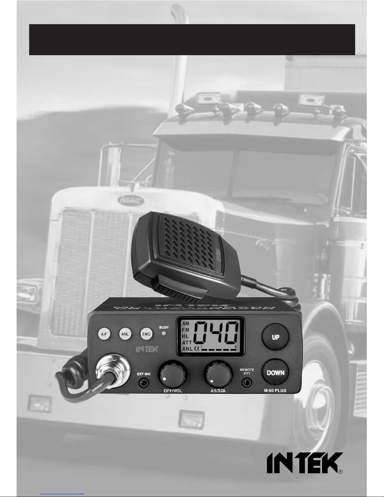
MULTI STANDARD PROGRAMMABLE
27 MHz CB MOBILE TRANSCEIVER
M-60 PLUS
OWNER'S MANUAL
MANUALE DI ISTRUZIONI
SAFE DRIVE RADIO !
KEEP YOUR HANDS ON THE STEERING
WHEEL WHILE DRIVING !
Downloaded from www.cbradio.nl
0678
NOTICE !
It is recommended to carefully read this owner’s manual before using the product. This will also help the user to
prevent using the radio in violation of the regulations valid in the country where the product is used, as well as to
avoid any possible interferences with other services.
CH
Declaration of Conformity
With the present declaration, we certify that the following products :
INTEK M-60 PLUS
comply with all the technical regulations applicable to the above mentioned products
in accordance with the EC Directives 2006/95/EC, 2004/108/EC, 99/5/EC.
Type of product : CB Transceiver
Details of applied standards : EN 300 433-1/-2, EN 300 135-1/-2
EN 301 489-1, EN 301 489-13
EN 60065
Manufacturer : INTEK S.R.L.
Via G. Marconi, 16
20090 Segrate, Italy
Tel. 39-02-26950451 / Fax. 39-02-26952185
E-mail : intek.com@intek-com.it
Notified Body : EMCCert Dr. Rasek
Boelwiese 5, 91320 Ebermannstadt
Germany
Identification Number : 0678
Contact Reference : Armando Zanni
Tel. 39-02-26950451 / Fax. 39-02-26952185
E-mail : intek.com@intek-com.it
Segrate, 24/02/2012 dr. Vittorio Zanetti
(General Manager)
DECLARATION OF CONFORMITY
EC Certificate of Conformity
(to EC Directive 2006/95, 2004/108, 99/5)
RoHS
2002/95/EC

Index - Introduction
- 1 -
Index - Introduction . . . . . . . . . . . . . . . . . . . . . . . . . . . . . . . . . . . . . . . . . . . . . . . . . . . . . . . . . . . . . . . . . 1
Unpacking and checking parts . . . . . . . . . . . . . . . . . . . . . . . . . . . . . . . . . . . . . . . . . . . . . . . . . . . . . . . . 2
Supplied Accessories . . . . . . . . . . . . . . . . . . . . . . . . . . . . . . . . . . . . . . . . . . . . . . . . . . . . . . . . . . . . . . . 2
Controls, Indicators and operation . . . . . . . . . . . . . . . . . . . . . . . . . . . . . . . . . . . . . . . . . . . . . . . . . . . 2-8
Installation . . . . . . . . . . . . . . . . . . . . . . . . . . . . . . . . . . . . . . . . . . . . . . . . . . . . . . . . . . . . . . . . . . . . . . . . 9
Frequency bands table - User Information . . . . . . . . . . . . . . . . . . . . . . . . . . . . . . . . . . . . . . . . . . . . . 10
Frequency band selection / programming . . . . . . . . . . . . . . . . . . . . . . . . . . . . . . . . . . . . . . . . . . . . . . 11
Table of restrictions on the use of CB transceivers . . . . . . . . . . . . . . . . . . . . . . . . . . . . . . . . . . . . . . 11
Specifications . . . . . . . . . . . . . . . . . . . . . . . . . . . . . . . . . . . . . . . . . . . . . . . . . . . . . . . . . . . . . . . . . . . . . 12
Table of restrictions on the use of CB transceivers . . . . . . . . . . . . . . . . . . . . . . . . . . . . . . . . . . . . . . . I
PCB - Main Board & Front Board . . . . . . . . . . . . . . . . . . . . . . . . . . . . . . . . . . . . . . . . . . . . . . . . . . . II-III
Diagram . . . . . . . . . . . . . . . . . . . . . . . . . . . . . . . . . . . . . . . . . . . . . . . . . . . . . . . . . . . . . . . . . . . . . . . . IV-V
Block Diagram . . . . . . . . . . . . . . . . . . . . . . . . . . . . . . . . . . . . . . . . . . . . . . . . . . . . . . . . . . . . . . . . . .VI-VII
Notes . . . . . . . . . . . . . . . . . . . . . . . . . . . . . . . . . . . . . . . . . . . . . . . . . . . . . . . . . . . . . . . . . . . . . . . . .VIII-IX
NOTICE !
Before using this transceiver, please check that the radio has been programmed on the frequency bands,
specifications and operating modes allowed by the regulations valid in the country where the product is used. If
not, please proceed to modify the frequency band programming, as it is described in this owner’s manual. This
transceiver is factory pre-programmed on the CE European frequency band (CEPT 40CH FM 4W).
Congratulations!
Congratulations for selecting and purchasing an INTEK quality product. This transceiver includes a number of advanced
functions and systems, therefore it is definitely necessary to carefully read this owner’s manual before using the radio.
With a correct use of the product in accordance with the operating method described in this manual, the product will offer
a trouble free use for many years. INTEK is constantly engaged to develop and provide quality products meeting the
customers requirements, however any suggestion or comment on this product that might help us to improve quality are
warmly welcome. INTEK M-60 PLUS is a CB transceiver using advanced hardware and software design, it includes a
special multi-standard programmable circuit, which allows to program the specifications of the radio (frequency
bands, operating modes, transmitter power) in compliance with the regulations valid in the various European
countries. Therefore this product can be used in any country of the European Community. The radio is delivered
factory pre-programmed on the CE European frequency band (CEPT 40CH FM 4W).
English
Unpacking and Checking Parts - Supplied Accessories
- 2 -
Unpacking and checking parts
Carefully unpack the product. Please identify all the parts listed below, before wasting the packaging. If any part is
missing or if the packaging shows any damage, please contact your dealer immediately.
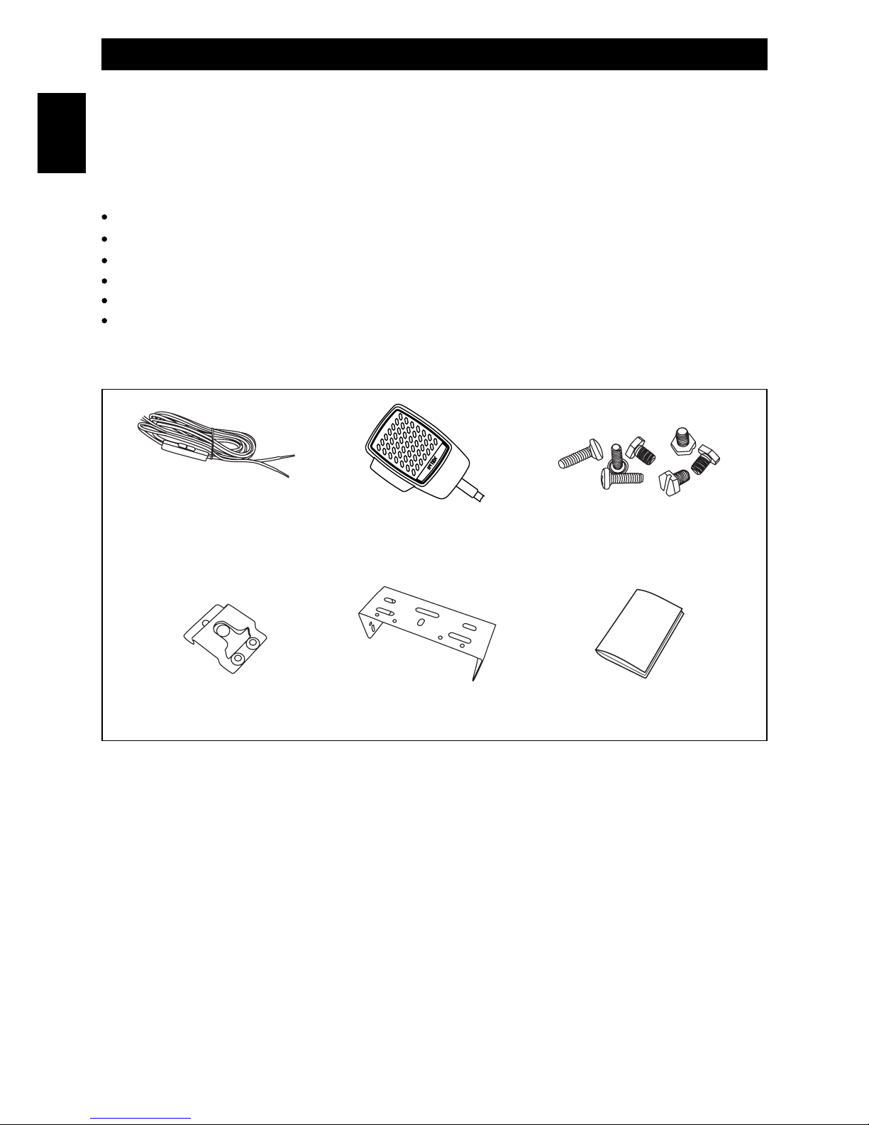
Supplied accessories
DC power cord with fuse holder and fuse, integrated with the transceiver
Standard microphone with 4-pin connector
Car mounting bracket
Car mounting bracket accessories (hardware, knobs, etc.)
Microphone bracket
Owner’s manual
Microphone bracket Car mounting bracket Owner's manual
Hardware
DC power cord with fuse holder and
fuse, integrated with the transceiver
Standard microphone
English
- 3 -
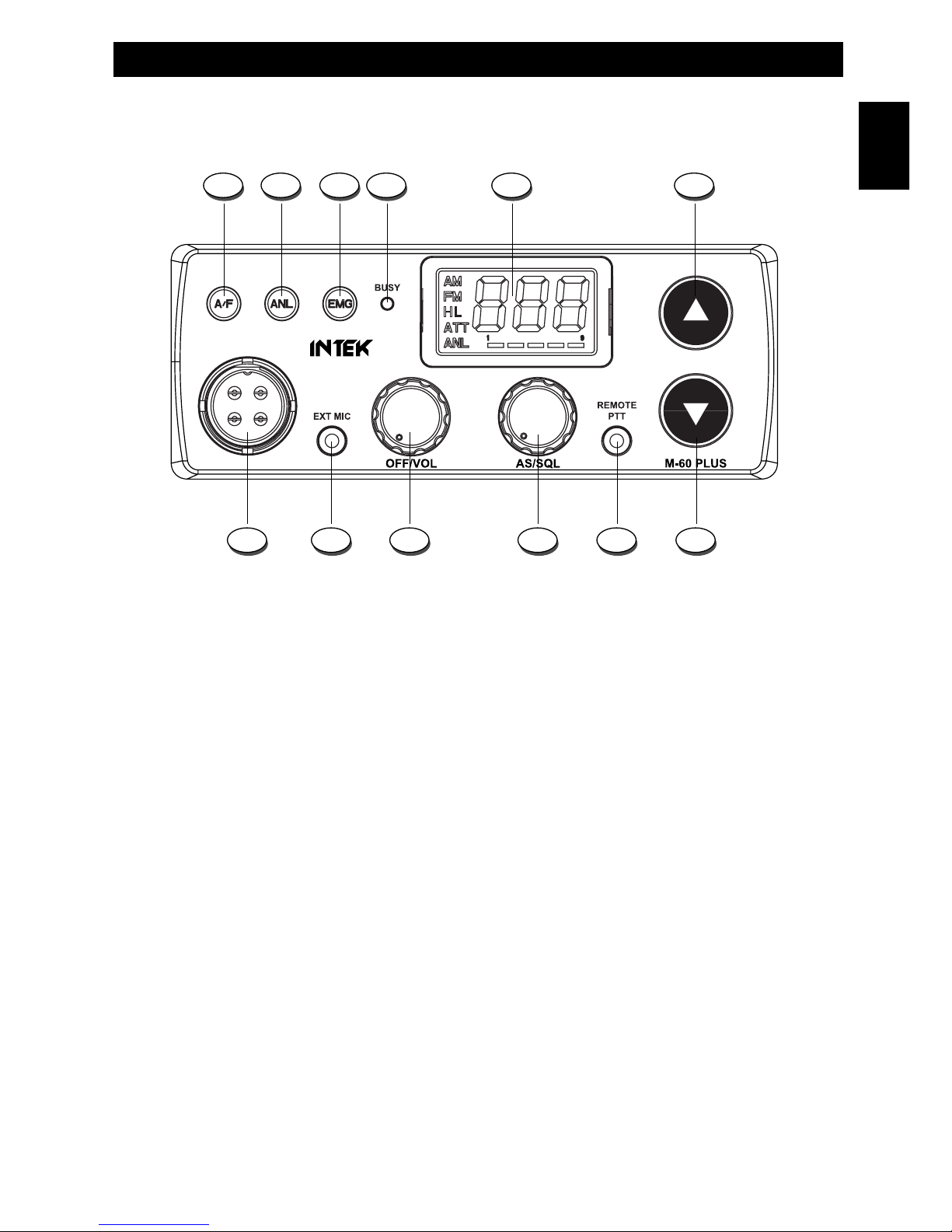
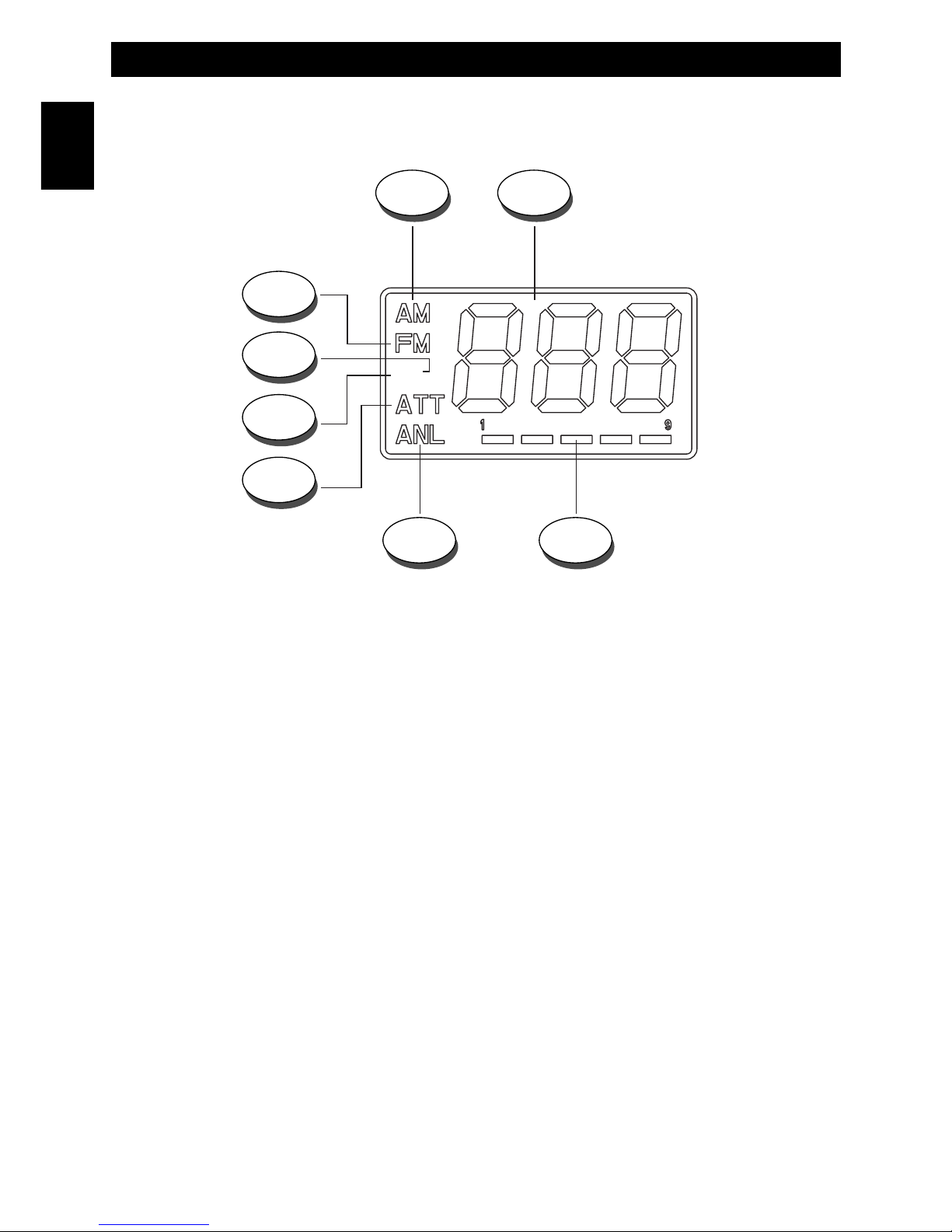
Controls, Indicators and operation
FRONT PANEL
1. A/F Key
This key allows to select the AM or FM operating mode, in both TX and RX. The AM/FM operating mode selection is
possible only if it if allowed by the programmed frequency band, otherwise the AM/FM selection is not possible.
2. ANL Key
Press the ANL key (3) to enable the ANL (Automatic Noise Limiter) function, in order to reduce electric or
electromagnetic noise or interference on the used channel. The ANL icon (D) is lighted to confirm that the ANL
function is enabled. Press again the ANL key (2) to disable the function.
3. EMG key (Emergency Channels)
This key allows quick access to one of the two pre-programmed emergency channels (CH9 or CH19). Each time this
key is pressed, radio will select CH9, then CH19, then again the normal operating channel.
4. BUSY Indicator. This green color LED indicator is lighted when radio is receiving one communication and the
squelch is open (radio is not in the automatic mute mode).
5. LCD Display
Large size LCD display with blue color backlight function for best readability in darkness. It indicates the operating
channel number, the operating mode, all the programmed settings and all the enabled functions.
1 2 3 4 5 6
7911 812 10
English
- 4 -
Controls, Indicators and operation
A. AM Icon
The AM icon (A) is lighted when radio has is set to the AM (Amplitude Modulation) operating mode.
B. Channel Number
It indicates the operating channel number or the frequency band ID code.
C. S/RF Digital Meter
The digital 5-bar S/RF METER (C) indicates the strength of the received signal (from S0 to S9+30) in the receive mode
and the transmitter RF output power (0 to 4W) in the transmit mode.
D. ANL Icon. The ANL Icon (D) is lighted when the ANL (Automatic Noise Limiter) is enabled.
E. ATT Icon. Not available on this model.
F. H Icon
The H Icon (F) is lighted when the transmitter is in HIGH POWER mode (4W).
G. L Icon
The L Icon (G) is lighted when the transmitter is in LOW POWER mode (1W).
H. FM Icon
The FM icon (H) is lighted when radio is set to the FM (Frequency Modulation) operating mode.
HL
A
H
G
B
CD
F
E
LCD DISPLAY
English

- 5 -
6. Up Key. Press to select the operating channel upward. By keeping a key pressed, the quick channel selection
mode will be enabled.
7. Down Key. Press to select the operating channel downward. By keeping a key pressed, the quick channel
selection mode will be enabled.
8. REMOTE PTT Jack
Connect here the optional Remote PTT Control (RPT-1). Refer to the section “TRANSMITTING MODES” at page 8.
9. AS/SQL Control
SQUELCH CONTROL (SQUELCH manual adjustment)
The SQUELCH control allows to silent the receiver by cutting the background noise, when no signals are received. Turn
the knob clockwise until the background noise is cut. Turn the knob counter clockwise (SQUELCH opening) in order to
listen to the weakest signals.
AS CONTROL (SQUELCH fixed setting)
The AS function allows to automatically silent the receiver, avoding the SQUELCH manual adjustment. A fixed
SQUELCH threshold is factory pre-set. To enable the fixed SQUELCH function, turn the knob fully counter clockwise to
the AS position, until a click noise is heard.
10. OFF/VOL Control
Use this knob to switch radio ON and OFF, as well as to adjust the receiver volume to the desired level. To adjust the
receiver volume in case no signals are received on the operating channel, open the SQUELCH and then adjust the
receiver volume using the background noise as a reference.
11. EXT MIC Jack
Connect here the optional external microphone ESM-444. Refer to the sections “TRANSMITTING MODES” at page 8.
12. Microphone Connector
Connect the standard 4-pin microphone to this connector and turn the connector ring to lock it.
Controls, Indicators and operation
English
IMPORTANT !
Do never attempt to open the cabinet of the transceiver. No user serviceable parts inside. Internal modifications or
tampering may cause damage to the product, modify its technical specifications and will void warranty rights. If
service or repair are required, please go to an authorised service centre or specialized technician.
Controls, Indicators and operation
- 6 -
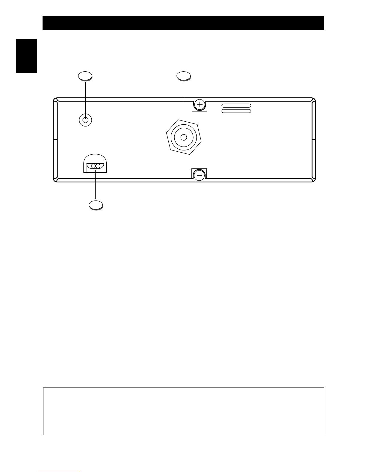
REAR PANEL
13. EXT (External Speaker) Jack
This jack is for connecting an external speaker (optional).
14. ANTENNA Connector
Antenna connector. Refer to the sections INSTALLATION OF THE ANTENNA.
15. 13.2VDC POWER CORD
13.2VDC power cord input.
English
ANT
EXT
DC
13.2V
1413
15
- 7 -
Controls, Indicators and operation
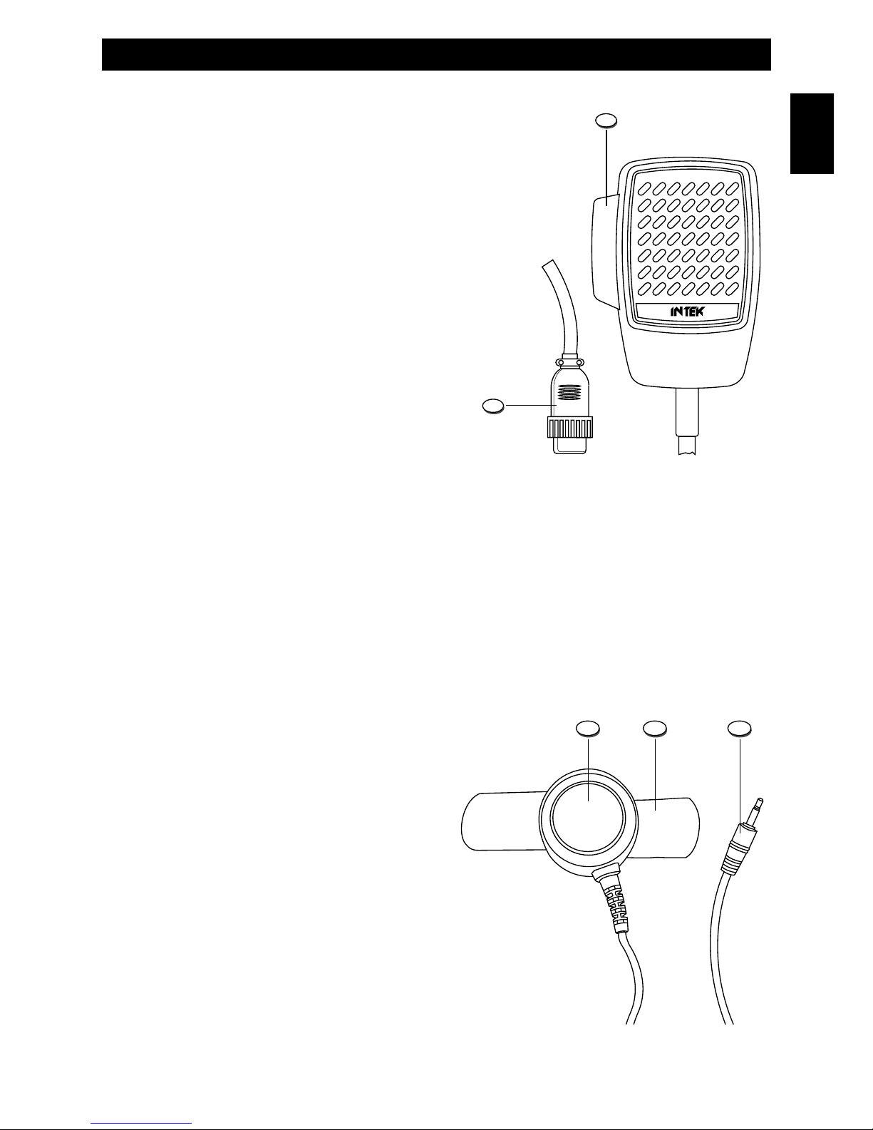
MICROPHONE WITH 4-PIN CONNECTOR
English
16. PTT (Push-to-Talk) Key
Transmitter key. Press the PTT key (16) to transmit and release it to
return to the receive mode.
17. MICROPHONE Plug
4-pin microphone connector with locking ring. Connect it to the
microphone connector (12) on the front panel of the radio.
16
17
REMOTE PTT CONTROL RPT-1 (OPTIONAL)
18. PTT (Push-to-Talk) Key
Transmitter key. Press the PTT key (18) to transmit and
release it to return to the receive mode.
19. Remote PTT Jack
Connect this jack to the REMOTE PTT socket (8) on the
front panel of the radio.
20. Velcro Strap
Velcro strap for installing the remote PTT control in a
convenient location, such as on the speed shift lever or
on the steering wheel.
18 20 19
- 8 -
TRANSMITTING MODES
OPERATION IN PTT MODE WITH STANDARD MICROPHONE (supplied)
Connect the 4-pin standard microphone to the microphone connector (12). Press and hold the PTT button (16) to
transmit and speak into microphone. Release the PTT button (16) to return to receive mode.
OPERATION IN PTT MODE WITH EXTERNAL MICROPHONE (optional)
AND REMOTE PTT CONTROL BOX (optional)
The optional external microphone (ESM-444) and remote PTT control Box (RPT-1) allow operating the radio in total
comfort and safety, without using the standard microphone that may be disconnected from the radio and removed.
Connect the microphone jack (23) into the EXT MIC socket (11). Connect the remote PTT control jack (19) to the
REMOTE PTT socket (8). Install the remote PTT control in a convenient location, such as on the speed shift lever or on
the steering wheel, using the velcro strap (20), for your most comfortable operation during driving.
WARNING ! Pay the greatest attention to installation of the remote PTT control and its connecting cable, in order
for these not to interfere with your driving operation.
Press and hold the PTT button (18) to transmit and speak into microphone (22) with normal voice. Release the PTT
button (18) to return to receive mode.
Controls, Indicators and operation
English
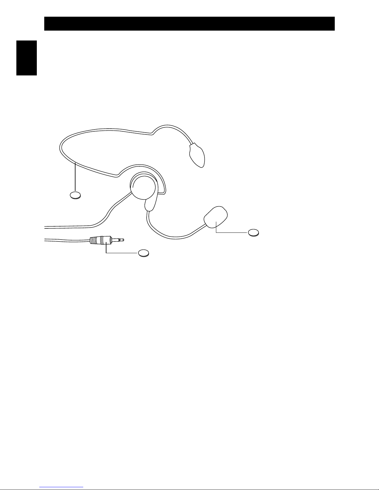
EXTERNAL MICROPHONE ESM-444 (OPTIONAL)
21. Neck Bracket
22. Microphone
23. Microphone Jack
Connect this jack to the EXT MIC socket (11) on the front panel of the radio.
23
22
21

- 9 -
Installation
Installation
Before installing the main unit in the vehicle, check and select the most convenient location, in order that the radio will be
easy to reach and comfortable to operate, without disturbing or interfering with the vehicle drive. Use the supplied
bracket and hardware to install the radio. The bracket screws must be well tightened in order not to become loosen with
the vehicle vibrations. The car mounting bracket can be installed over or below the radio and the radio may be inclined
as desired according to the specific type of installation (under dashboard or track cabin roof installation).
Installation of the Main Unit
Before connecting the radio to the vehicle electric system, make sure that radio is switched off, with the OFF/VOL knob
(10) completely turned counter clockwise at OFF position. The DC power cable (15) of the radio is complete with a fuse
holder with fuse located on the red positive (+) wire. Connect the DC power cable to the vehicle electric system, with
special attention to respect correct polarity, even if the radio is protected against polarity inversion. Connect the red wire to
the positive (+) pole and the black wire to the negative (-) pole of the vehicle electric system. Make sure that the wires and
terminals are firmly and stably connected, in order to prevent cables from disconnecting or causing short circuits.
Installation of the Antenna
A specific mobile antenna adjusted for 27 MHz frequency range must be used. The antenna installation must be done by
a specialised technician or service centre. Please pay special attention to carefully install the antenna on the vehicle with
perfect connection to ground. Before connecting the antenna to the radio, it is necessary to check the correct operation
of the antenna with low standing wave ratio (S.W.R.), using adequate instruments. If not, the transmitter circuit of the
radio could be damaged. The antenna must be usually installed on the highest part of the vehicle, free from obstacles
and as far away as possible from any source of electric or electromagnetic noise. The RF antenna coaxial cable must
not be damaged or pressed on its way between antenna and the radio. The correct operation of the antenna and the low
standing wave ratio (S.W.R.) must be checked periodically. Connect the RF antenna coaxial cable to the antenna
connector (14), located on the rear side of the radio.
Checking Operation of the Radio
Once radio has been connected to the vehicle electric system and to the antenna, the correct operation of the system
may be checked. Please proceed as follows :
1) Check that the power cable (15) is correctly connected.
2) Check that the RF antenna coaxial cable is correctly connected.
3) Connect the standard 4-pin microphone to the connector (12), located on the front side of the radio.
4) Rotate the AS/SQL knob (9) counter clockwise.
5) Turn radio on using the OFF/VOL knob (10) and adjust volume to the desired level.
6) Select the desired channel, using the Up/Down Keys (6, 7).
7) Rotate the AS/SQL knob (9) clockwise, to cut the background noise.
8) Press the PTT key (16) to transmit and release it to receive.
English
 Loading...