

Intek M-550 POWER Owner's Manual
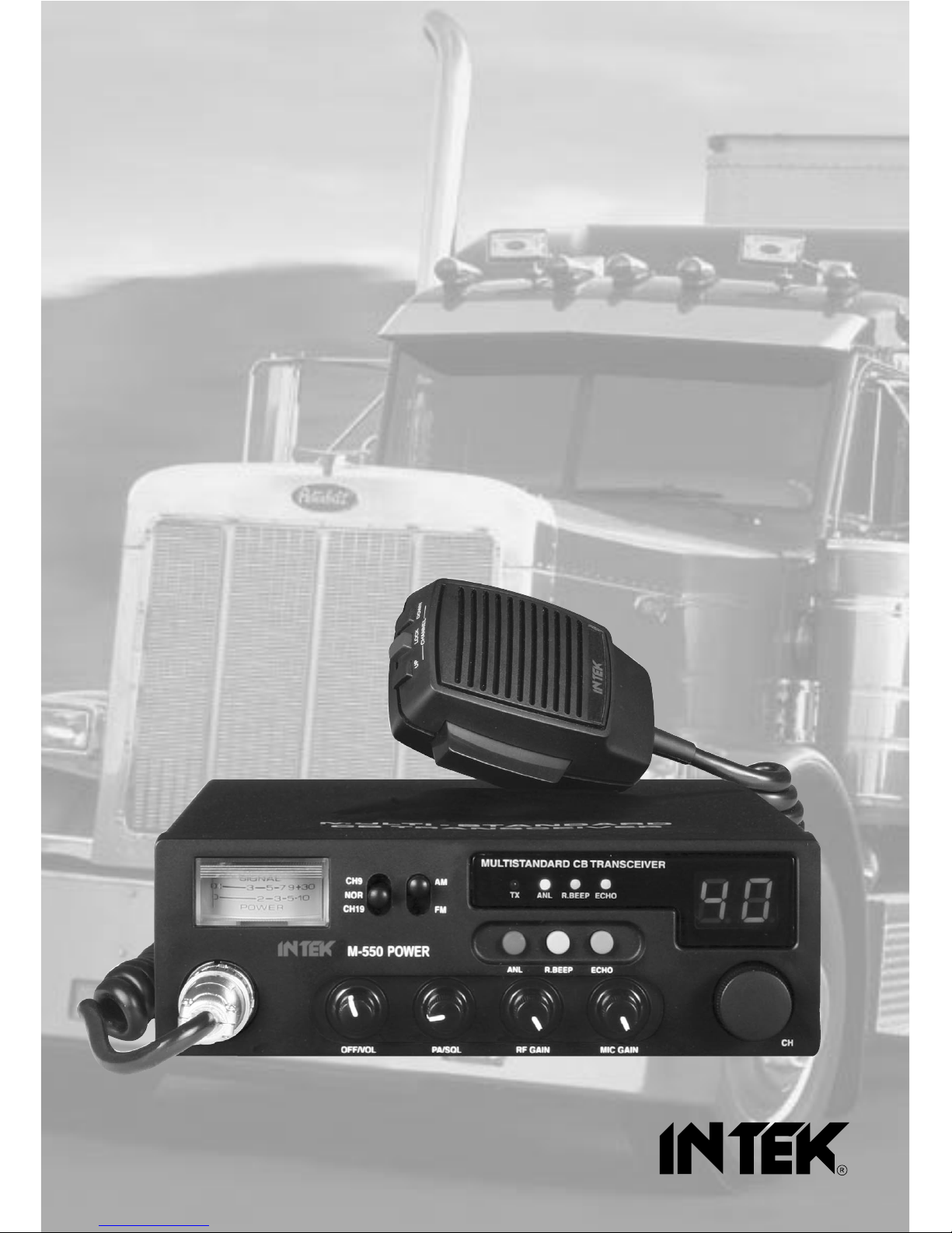
OWNER'S MANUAL
MANUALE DI ISTRUZIONI
MULTI STANDARD PROGRAMMABLE
27 MHz CB MOBILE TRANSCEIVER
M-550 POWER
Declaration of Conformity
With the present declaration, we certify that the following products :
INTEK M-550 POWER
comply with all the technical regulations applicable to the above mentioned products
in accordance with the EC Directives 73/23/EEC, 89/336/EEC and 99/5/EC.
Type of product : CB Transceiver
Details of applied standards : EN 300 433, EN 300 135-2
EN 301 489-1, EN 301 489-13
EN 60065
Manufacturer : INTEK S.R.L.
Via G. Marconi, 16
20090 Segrate, Italy
Tel. 39-02-26950451 / Fax. 39-02-26952185
E-mail : intek.com@intek-com.it
Notified Body : EMCCert Dr. Rasek
Boelwiese 5, 91320 Ebermannstadt
Germany
Identification Number : 0678
Contact Reference : Armando Zanni
Tel. 39-02-26950451 / Fax. 39-02-26952185
E-mail : intek.com@intek-com.it
Segrate, 30/08/2006 dr. Vittorio Zanetti
(General Manager)
DECLARATION OF CONFORMITY
EC Certificate of Conformity
(to EC Directive 99/5-89/336-93/68-73/23)
0678
NOTICE !
It is recommended to carefully read this owner’s manual before using the product. This will also help the user to
prevent using the radio in violation of the regulations valid in the country where the product is used, as well as to
avoid any possible interferences with other services.
CH
RoHS
2002/95/EC

car mounting bracket accessories (hardware, knobs, etc.)
microphone bracket
owner’s manual
Index - Introduction - Content of the packaging
- 1 -
Index . . . . . . . . . . . . . . . . . . . . . . . . . . . . . . . . . . . . . . . . . . . . . . . . . . . . . . . . . . . . . . . . . . . . . . . . . . . . . .1
Introduction / Content of the packaging . . . . . . . . . . . . . . . . . . . . . . . . . . . . . . . . . . . . . . . . . . . . . . . . 1
Controls and operation . . . . . . . . . . . . . . . . . . . . . . . . . . . . . . . . . . . . . . . . . . . . . . . . . . . . . . . . . . . 2 - 5
Installation . . . . . . . . . . . . . . . . . . . . . . . . . . . . . . . . . . . . . . . . . . . . . . . . . . . . . . . . . . . . . . . . . . . . . . . . 6
Frequency bands table . . . . . . . . . . . . . . . . . . . . . . . . . . . . . . . . . . . . . . . . . . . . . . . . . . . . . . . . . . . . . . 7
Frequency band selection / programming . . . . . . . . . . . . . . . . . . . . . . . . . . . . . . . . . . . . . . . . . . . . . . 8
Table of restrictions on the use of CB transceivers . . . . . . . . . . . . . . . . . . . . . . . . . . . . . . . . . . . . . . . 8
Specifications . . . . . . . . . . . . . . . . . . . . . . . . . . . . . . . . . . . . . . . . . . . . . . . . . . . . . . . . . . . . . . . . . . . . . . 9
Table of restrictions on the use of CB transceivers . . . . . . . . . . . . . . . . . . . . . . . . . . . . . . . . . . . . . . . I
Diagram . . . . . . . . . . . . . . . . . . . . . . . . . . . . . . . . . . . . . . . . . . . . . . . . . . . . . . . . . . . . . . . . . . . . . . . .II - III
Block Diagram . . . . . . . . . . . . . . . . . . . . . . . . . . . . . . . . . . . . . . . . . . . . . . . . . . . . . . . . . . . . . . . . . . IV-V
PCB - Main Board & CPU Board . . . . . . . . . . . . . . . . . . . . . . . . . . . . . . . . . . . . . . . . . . . . . . . . . . . VI-VII
PCB - ECHO Board (ECHO-550P) . . . . . . . . . . . . . . . . . . . . . . . . . . . . . . . . . . . . . . . . . . . . . . . . . VIII-IX
Notes . . . . . . . . . . . . . . . . . . . . . . . . . . . . . . . . . . . . . . . . . . . . . . . . . . . . . . . . . . . . . . . . . . . . . . . . . X-XI
English
NOTICE !
Before using this transceiver, please check that the radio has been programmed on the frequency bands,
specifications and operating modes allowed by the regulations valid in the country where the product is used. If
not, please proceed to modify the frequency band programming, as it is described in this owner’s manual. This
transceiver is factory pre-programmed on the CE European frequency band (CEPT 40CH FM 4W).
Congratulations!
Congratulations for selecting and purchasing an INTEK quality product. This transceiver includes a number of advanced
functions and systems, therefore it is definitely necessary to carefully read this owner’s manual before using the radio.
With a correct use of the product in accordance with the operating method described in this manual, the product will offer
a trouble free use for many years. INTEK is constantly engaged to develop and provide quality products meeting the
customers requirements, however any suggestion or comments on this product that might help us to improve quality are
warmly welcome. INTEK M-550 POWER is a CB transceiver using advanced hardware and software design, it
includes a special multi-standard programmable circuit, which allows to program the specifications of the radio
(frequency bands, operating modes, transmitter power) in compliance with the regulations valid in the various
European countries. Therefore this product can be used in any country of the European Community. The radio is
factory pre-programmed on the CE European frequency band (CEPT 40CH FM 4W).
Content of the packaging
Please check that all the following items are contained in the packaging :
main unit (transceiver)
DC power cord with fuse holder and fuse
condenser microphone
car mounting bracket
Controls and operation
- 2 -
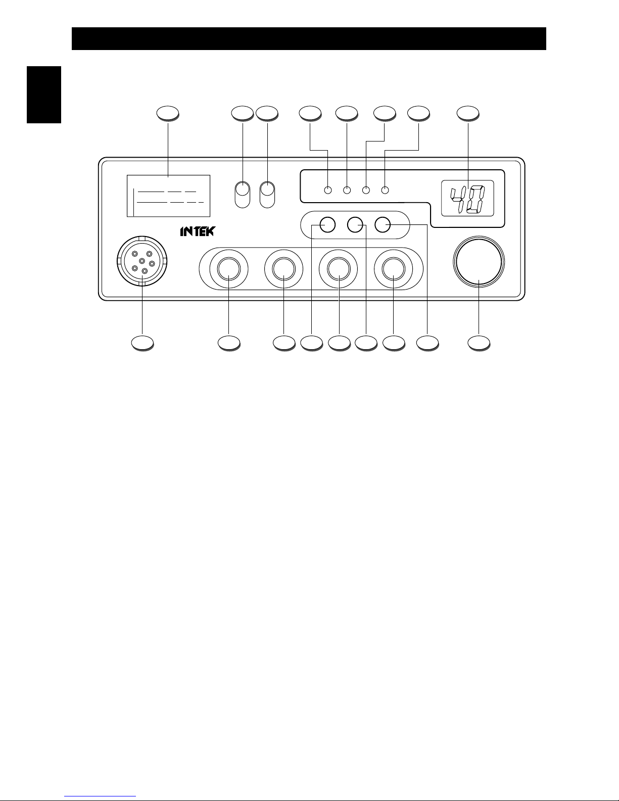
Front Panel
English
1. Analogue S/RF Meter
The analogue S/RF Meter indicates the received signal strenght (from S0 to S9+30) and the transmitter RF output
power.
2. CH9 / CH19 Selector
This 3-position switch allows to select the emergency channels CH9 and CH19 in the programmed frequency band. If
the switch is set to its center position, radio will operate on the normal selected channel.
3. AM / FM Selector
This switch allows to select the operating mode AM or FM, in both TX and RX, if the desired operating mode is enabled
by the programmed frequency band.
UK / CE SELECTOR
If the UK (United Kingdom) frequency band has been programmed, set the switch to the AM position to select the CE
channels (frequencies) or set the switch to the FM position to select the UK channels (frequencies).
4. TX Indicator
This red color LED indicator is lighted when radio is in the transmit mode.
5. ANL Indicator
This green color LED indicator is lighted when the ANL function is enabled.
6 R. BEEP Indicator
This green color LED indicator is lighted when the Roger Beep function is enabled.
MULTISTANDARD CB TRANSCEIVER
ANL R.BEEP ECHO
ANL R.BEEP ECHO
TX
CH9
NOR
CH19
AM
FM
MIC GAIN
CH
RF GAINPA/SQLOFF/VOL
M-550 POWER
01 01
SIGNAL
POWER
01 7
023510
9
+30
1 2 3 4 6 75 8
91113151617 14 12 10

Controls and operation
- 3 -
English
7 ECHO Indicator
This green color LED indicator is lighted when the ECHO function is enabled. The ECHO function can be used only if the
optional ECHO card (mod. ECHO-550P) has been installed.
5. LED Display
The large size two-digit LED display indicates the operating channel and the programmed frequency band code.
9. CHANNEL Selector
This knob selects the channel number, by one channel steps. The knob may be turned clockwise to select channels
upward or counter clockwise to select channels downward.
10. ECHO Key
This key enables the ECHO functtion.
The ECHO function can be used only if the optional ECHO card (mod.
ECHO-550P) has been installed. For installation of the ECHO card, please refer to the instructions included in the
package of the ECHO card.
11. MIC GAIN Control
This transceiver uses a high quality dynamic microphone. The microphone gain is adjustable with the MIC GAIN control.
By turning the knob clockwise, the microphone gain is increased.
12. R. BEEP Key
This key enables the Roger Beep function (automatic beep tone at the end of each transmission).
13. RF GAIN Control
This transceiver uses a high sensitivity and selectivity receiver circuit. The receiver gain is adjustable with the RF GAIN
control. By turning the knob clockwise, the receiver gain is increased. It is convenient to reduce the receiver gain in case
of very strong signals from local stations and to increase it in case of weak signals or long distance communications.
14. ANL Key / ANL Indicator
Thi key enables the ANL (Automatic Noise Limiter) function, in order to reduce electric or electromagnetic
noise or interference on the used channel. The green color LED indicator (5) is lighted to confirm that the
ANL function is enabled. Press again the ANL key (14) to disable the function.
15. PA/SQL Control
SQUELCH CONTROL
The SQUELCH control allows to silent the receiver by cutting the background noise.
Turn the SQUELCH knob clockwise until the background noise is cut. Turn the SQUELCH knob counter clockwise
(SQUELCH opening) to listen to the weakest signals.
PA CONTROL
The radio includes the PA (Public Address) function, in order to spread audio messages through an external speaker. To
use the PA function, connect an external speaker (optional) to the PA jack (19) located on the rear side of the radio. Turn
the PA/SQL knob completely counter clockwise to the PA position. The LED display will show PA. Now it is possible to
press the PTT key (22) and speak into the microphone to spread your message through the external speaker. Adjust the
microphone gain with the MIC GAIN knob (11) to the desired level.
Controls and operation
- 4 -
English
16. OFF/VOL (OFF / Volume) Control
This knob switches the radio ON and OFF and it adjusts the volume control. If no signals are being received on the
operating channel, it is suggested to open the SQUELCH and adjust the volume to the desired level while listening to the
background noise.
17. MICROPHONE Connector
Connect the supplied dynamic microphone to this connector, locking it through the ring nut.
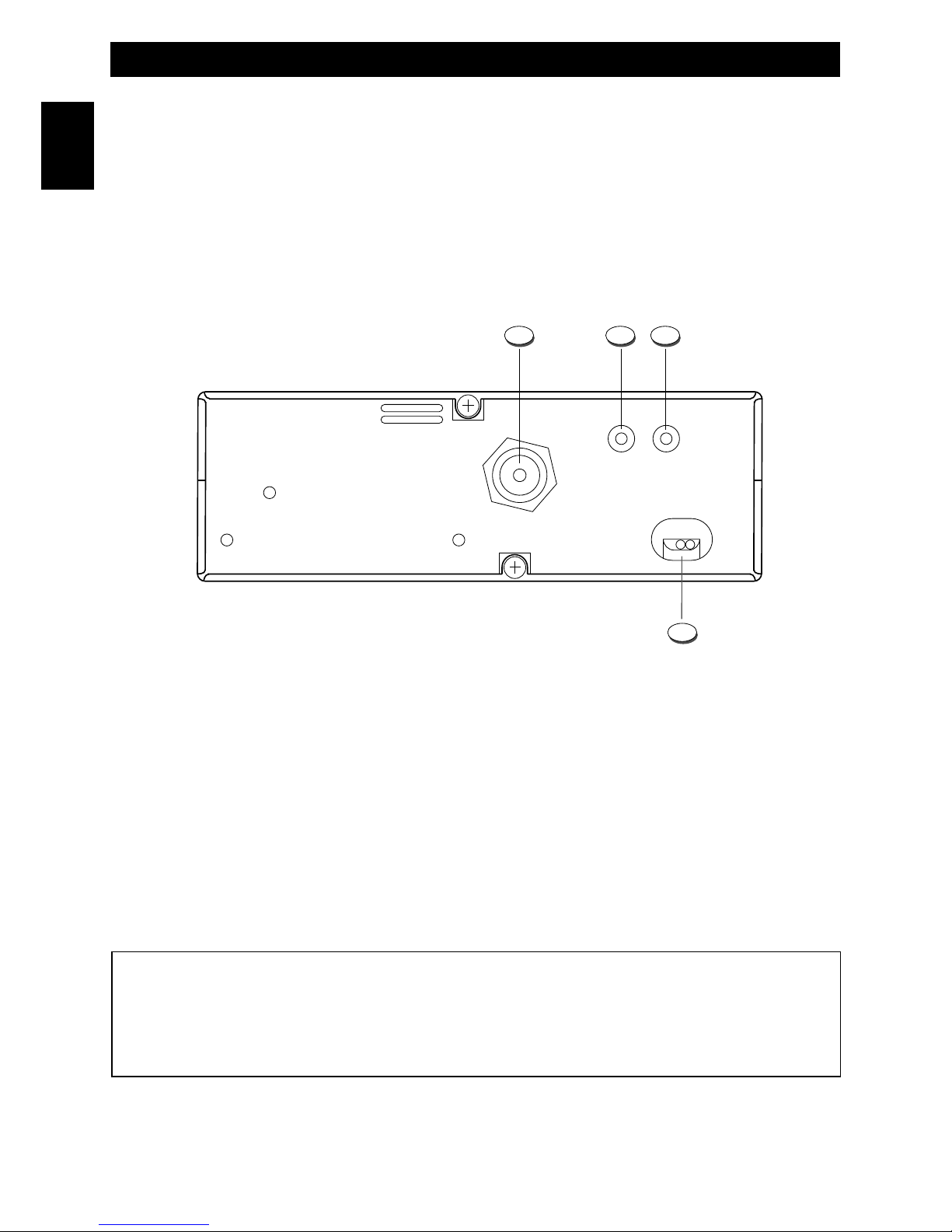
Rear Panel
18. ANTENNA Connector
Antenna connector. Refer to the section INSTALLATION OF THE ANTENNA.
19. PA Jack
If the PA function has to be used, connect to the external speaker (optional) to this jack. Refer to item no. 15
20. EXT (External Speaker) Jack
This jack is for connecting an external speaker (optional).
21. 13.2VDC POWER CORD
13.2VDC power cord input.
19 20
21
ANTENNA
EXTPA
POWER
13.2V DC
18
IMPORTANT !
Do never attempt to open the cabinet of the transceiver. No user serviceable parts inside. Internal modifications or
tampering may cause damage to the product, modify its technical specifications and will void warranty rights. If
service or repair are required, please go to an authorised service centre or specialized technician.

Controls and operation
- 5 -
English
Microphone
22. PTT (Push-to-Talk) Key
Transmitter key. Press the PTT key to transmit and release it to return to the receive mode.
23. UP (Channel Selector) Key
Each time this key is pressed, the channel number will move upward by one channel.
24. LOCK (Keypad Lock) Key
Press the LOCK key (24) to enable the LOCK function, in order lock the keypad and prevent entering unwanted
commands. When the LOCK function is enabled, if you try to press any of the keys, the LED display will show LO.
25. DOWN (Channel Selector) Key
Each time this key is pressed, the channel number will move downward by one channel.
26. MICROPHONE Plug
6-pole microphone plug with locking ring nut, to be connected to the microphone connector (17) located on the front side
of the radio.
242322
26
25

Installation
- 6 -
English
Installation
Before installing the main unit in the vehicle, check and select the most convenient location, in order that the radio will be
easy to reach and comfortable to operate, without disturbing or interfering with the vehicle drive. Use the supplied
bracket and hardware to install the radio. The bracket screws must be well tightened in order not to become loosen with
the vehicle vibrations. The car mounting bracket can be installed over or below the radio and the radio may be inclined
as desired according to the specific type of installation (under dashboard or track cabin roof installation).
Installation of the Main Unit
Before connecting the radio to the vehicle electric system, make sure that radio is switched off, with the OFF/VOL (16)
knob completely turned counter clockwise at OFF position. The DC power cable (13) of the radio is complete with a fuse
holder with fuse located on the red positive (+) wire. Connect the DC power cable to the vehicle electric system, with
special attention to respect correct polarity, even if the radio is protected against polarity inversion. Connect the red wire
to the positive (+) pole and the black wire to the negative (-) pole of the vehicle electric system. Make sure that the wires
and terminals are firmly and stably connected, in order to prevent cables from disconnecting or causing short circuits.
Installation of the Antenna
A specific mobile antenna adjusted for 27 MHz frequency range must be used. The antenna installation must be done by
a specialised technician or service centre. Please pay special attention to carefully install the antenna on the vehicle with
perfect connection to ground. Before connecting the antenna to the radio, it is necessary to check the correct operation
of the antenna with low standing wave ratio (S.W.R.), using adequate instruments. If not, the transmitter circuit of the
radio could be damaged. The antenna must be usually installed on the highest part of the vehicle, free from obstacles
and as far away as possible from any source of electric or electromagnetic noise. The RF antenna coaxial cable must
not be damaged or pressed on its way between antenna and the radio. The correct operation of the antenna and the low
standing wave ratio (S.W.R.) must be checked periodically. Connect the RF antenna coaxial cable to the antenna
connector (18), located on the rear side of the radio.
Checking Operation of the Radio
Once radio has been connected to the vehicle electric system and to the antenna, the correct operation of the system
may be checked. Please proceed as follows :
1) Check that the power cable is correctly connected.
2) Check that the RF antenna coaxial cable is correctly connected.
3) Connect the microphone to the connector (17), located on the front side of the radio.
4) Rotate the PA/SQL (15) knob counter clockwise.
5) Turn radio on using the OFF/VOL (16) knob and adjust volume to the desired level.
6) Select the desired channel, using the channel selector (9).
7) Rotate the PA/SQL (15) knob clockwise, to cut the background noise.
8) Press the PTT (22) key to transmit and release it to receive.
The transceiver will work correctly.

Frequency bands table
- 7 -
English
Frequency Bands Table
The transceiver INTEK M-550 POWER includes an advanced multi-standard programmable circuit, which allows to
program different frequency bands, specifications and operating modes, in conformity with the regulations in the country
where the product is used. 8 programmable frequency bands are available, as per the below table :
Attention ! This radio has been factory pre-programmed on the CE frequency band (CEPT 40CH FM 4W), since this
standard is currently accepted in all the European countries. Please refer to the information table at pag. I (Restrictions
on the use of CB transceivers).
COUNTRY CODE COUNTRY
SPECIFICATIONS (CH, operating modes, TX power)
01 ITALY / SPAIN
40CH AM / FM 4W
02 ITALY
36CH AM / FM 4W
03 GERMANY
80CH FM 4W - 12CH AM 1W
04 GERMANY
40CH FM 4W - 12CH AM 1W
05 EUROPE / FRANCE
40CH FM 4W - 40CH AM 1W
06 CEPT
40CH FM 4W
07 UK
40CH FM 4W UK FREQUENCIES 40CH FM 4W CEPT FREQUENCIES
08 POLAND
40CH AM / FM 4W POLISH FREQUENCIES

Frequency band selection / Programming
- 8 -
English
Frequency Band Selection / Programming
This two-way CB radio must be programmed and exclusively used on a frequency band allowed in the country where
the product is used.
To program a different frequency band, proceed as follows :
1) Turn OFF the radio.
2) Press and keep pressed the ECHO key (10), then turn ON the radio using the OFF/VOL knob (16).
3) The current frequency band code will blink on the display (8).
4) Now select the new desired frequency band code using the channel selector knob (9).
5) Press the ECHO key (10) to confirm and store the new selected frequency band code.
Each time radio is switch on, the LED display will indicate for a few seconds the band code of the last programmed
band.
Table of Restrictions on the Use of CB Transceivers (page. I)
The following information are to be considered only just as an indication. They are believed to be correct at the time of
printing this operating manual. It is however the user’s responsibility to check that, in the country where radio is used, the
regulations for the use of CB transceivers have not been modified. User is therefore suggested to contact the local
dealer or local authority, in order to check the current regulations for the use of CB transceivers, before operating this
product. The manufacturer does not take any responsibility if the product is used in violation of the regulations of the
country where the product is used.
Addendum (Updated information on national restrictions)
BELGIUM, UK, SPAIN, SWITZERLAND
In order to use this transceiver in Belgium, UK, Spain and Switzerland, residence must have an individual licence. Users
coming from abroad may freely use the radio in FM mode, while in order to use it in AM mode they must hold a licence
released in their own country.
ITALY
Foreigners arriving in Italy must get an Italian authorization.
AUSTRIA
Austria does not allow using multi standard programmable CB radios. It is recommended
to carefully follow this directives and not to use the product in the Austrian territory.
GERMANY
Along some border areas in Germany, the radio can not be used as a base station from
channel 41 to channel 80. Refer to local authority (notification office) for details.
WARNING !
This mobile transceiver includes a state-of-the-art high power MOSFET type transmitter. All radios for the
european countries are factory preset with the transmitter RF output power limited to 4W, in accordance with the
current R&TTE regulations. This factory preset configuration can not be modified by the user. INTEK declines any
responsability for any modification or tampering of the product, made by the user after purchase.
 Loading...