

Intek M-100 PLUS, M-120 PLUS, M-130 PLUS Owner's Manual
MULTI STANDARD PROGRAMMABLE
27 MHz CB MOBILE TRANSCEIVER
M-100 PLUS
OWNER'S MANUAL
MANUALE DI ISTRUZIONI
0678
NOTICE !
It is recommended to carefully read this owner’s manual before using the product. This will also help the user to
prevent using the radio in violation of the regulations valid in the country where the product is used, as well as to
avoid any possible interferences with other services.
CH
Declaration of Conformity
With the present declaration, we certify that the following products :
INTEK M-100 PLUS
comply with all the technical regulations applicable to the above mentioned products
in accordance with the EC Directives 2006/95/EC, 2004/108/EC, 99/5/EC.
Type of product : CB Transceiver
Details of applied standards : EN 300 433-1/-2, EN 300 135-1/-2
EN 301 489-1, EN 301 489-13
EN 60065
Manufacturer : INTEK S.R.L.
Via G. Marconi, 16
20090 Segrate, Italy
Tel. 39-02-26950451 / Fax. 39-02-26952185
E-mail : intek.com@intek-com.it
Notified Body : EMCCert Dr. Rasek
Boelwiese 5, 91320 Ebermannstadt
Germany
Identification Number : 0678
Contact Reference : Armando Zanni
Tel. 39-02-26950451 / Fax. 39-02-26952185
E-mail : intek.com@intek-com.it
Segrate, 31/10/2008 dr. Vittorio Zanetti
(General Manager)
DECLARATION OF CONFORMITY
EC Certificate of Conformity
(to EC Directive 2006/95, 2004/108, 99/5)
RoHS
2002/95/EC
car mounting bracket accessories (hardware, knobs, etc.)
microphone bracket
mobile antenna with magnet base (Full Kit version)
owner’s manual
Index - Introduction - Content of the packaging
- 1 -
Index - Introduction - Content of the packaging . . . . . . . . . . . . . . . . . . . . . . . . . . . . . . . . . . . . . . . . . .1
Controls and operation . . . . . . . . . . . . . . . . . . . . . . . . . . . . . . . . . . . . . . . . . . . . . . . . . . . . . . . . . . . 2 - 5
Installation . . . . . . . . . . . . . . . . . . . . . . . . . . . . . . . . . . . . . . . . . . . . . . . . . . . . . . . . . . . . . . . . . . . . . . . . 6
Installing and connecting the mobile antenna with magnet base (Full Kit Version) . . . . . . . . . . . . . 7
Frequency bands table - User Information . . . . . . . . . . . . . . . . . . . . . . . . . . . . . . . . . . . . . . . . . . . . . . 8
Frequency band selection / programming . . . . . . . . . . . . . . . . . . . . . . . . . . . . . . . . . . . . . . . . . . . . . . 9
Table of restrictions on the use of CB transceivers . . . . . . . . . . . . . . . . . . . . . . . . . . . . . . . . . . . . . . . 9
Specifications . . . . . . . . . . . . . . . . . . . . . . . . . . . . . . . . . . . . . . . . . . . . . . . . . . . . . . . . . . . . . . . . . . . . . 10
Table of restrictions on the use of CB transceivers . . . . . . . . . . . . . . . . . . . . . . . . . . . . . . . . . . . . . . . I
PCB - Main Board & Front Board . . . . . . . . . . . . . . . . . . . . . . . . . . . . . . . . . . . . . . . . . . . . . . . . . . . II-III
Diagram . . . . . . . . . . . . . . . . . . . . . . . . . . . . . . . . . . . . . . . . . . . . . . . . . . . . . . . . . . . . . . . . . . . . . . . . IV-V
Block Diagram . . . . . . . . . . . . . . . . . . . . . . . . . . . . . . . . . . . . . . . . . . . . . . . . . . . . . . . . . . . . . . . . . .VI-VII
Notes . . . . . . . . . . . . . . . . . . . . . . . . . . . . . . . . . . . . . . . . . . . . . . . . . . . . . . . . . . . . . . . . . . . . . . . . .VIII-IX
NOTICE !
Before using this transceiver, please check that the radio has been programmed on the frequency bands,
specifications and operating modes allowed by the regulations valid in the country where the product is used. If
not, please proceed to modify the frequency band programming, as it is described in this owner’s manual. This
transceiver is factory pre-programmed on the CE European frequency band (CEPT 40CH FM 4W).
Congratulations!
Congratulations for selecting and purchasing an INTEK quality product. This transceiver includes a number of advanced
functions and systems, therefore it is definitely necessary to carefully read this owner’s manual before using the radio.
With a correct use of the product in accordance with the operating method described in this manual, the product will offer
a trouble free use for many years. INTEK is constantly engaged to develop and provide quality products meeting the
customers requirements, however any suggestion or comment on this product that might help us to improve quality are
warmly welcome. INTEK M-100 PLUS is a CB transceiver using advanced hardware and software design, it includes
a special multi-standard programmable circuit, which allows to program the specifications of the radio (frequency
bands, operating modes, transmitter power) in compliance with the regulations valid in the various European
countries. Therefore this product can be used in any country of the European Community. The radio is delivered
factory pre-programmed on the CE European frequency band (CEPT 40CH FM 4W).
Content of the packaging
Please check that all the following items are contained in the packaging :
main unit (transceiver)
DC power cord with fuse holder and fuse
power cord with lighter adaptor plug
and fuse (Full Kit version)
condenser microphone
car mounting bracket
English
- 2 -
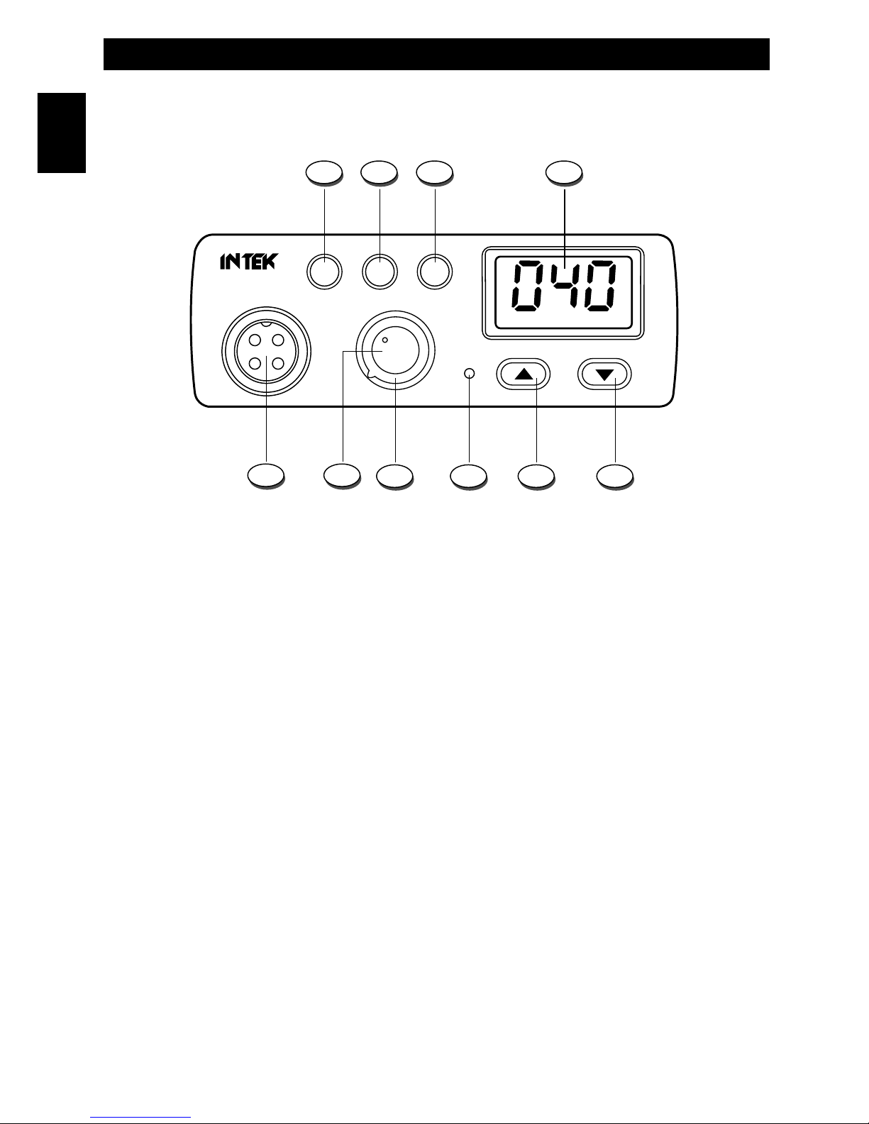
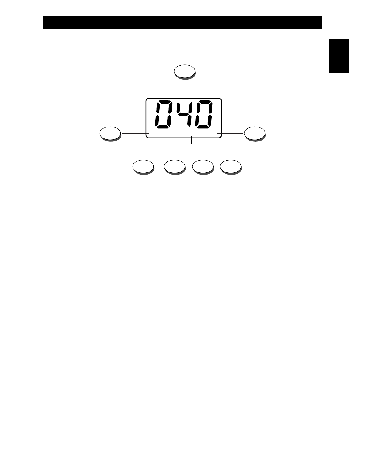
Controls, Indicators and operation
Front Panel
1. A/F Key
This key allows to select the AM or FM operating mode, in both TX and RX. The AM/FM operating mode selection is
possible only if it if allowed by the programmed frequency band, otherwise the AM/FM selection is not possible.
2. ANL Key
Press the ANL key (2) to enable the ANL (Automatic Noise Limiter) function, in order to reduce electric or
electromagnetic noise or interference on the used channel. The ANL (E) icon is lighted to confirm that the ANL
function is enabled. Press again the ANL key (2) to disable the function.
3. EMG key (Emergency Channels)
This key allows quick access to one of the two pre-programmed emergency channels (CH9 or CH19). Each time this key is
pressed, radio will select CH9, then CH19, then again the normal operating channel.
4. LCD Display
Large size LCD display with blue color backlight function for best readability in darkness. It indicates the
operating channel number, the operating mode and all the programmed settings and all the enabled
functions.
TX
VOL/OFF SQL
M-100 PLUS
CH
UP DN
A/F ANL EMG
AM FM HILOANL ALPHA
1 2 3 4
5678
10 9
English
- 3 -
English
Controls, Indicators and operation
A. Channel Number
It indicates the operating channel number or the frequency band ID code.
B. ALPHA Icon
The ALPHA Icon (B) is lighted when an intermediate channel is selected.
This feature is not available on the radios for the European Market.
C. LO Icon
The LO Icon (C) is lighted when the transmitter is in LOW POWER mode (1W).
D. HI Icon
The HI Icon (D) is lighted when the transmitter is in HIGH POWER mode (4W).
E. ANL Icon
The ANL Icon (E) is lighted when the ANL (Automatic Noise Limiter) function is enabled.
F. FM Icon
The FM icon (F) is lighted when radio has been set to the FM (Frequency Modulation) operating mode.
G. AM Icon
The AM icon (G) is lighted when radio has been set to the AM (Amplitude Modulation) operating mode.
5. DN (Down) Key
This key allows to select the operating channel downward. By keeping this key pressed, the quick channel selection
mode will be enabled.
6. UP (Up) Key
This key allows to select the operating channel upward. By keeping this key pressed, the quick channel selection mode
will be enabled.
7. TX Indicator
This red color LED indicator is lighted when radio is in the transmit mode.
AM FM HILOANL ALPHA
A
F DE C
BG
LCD Display
- 4 -
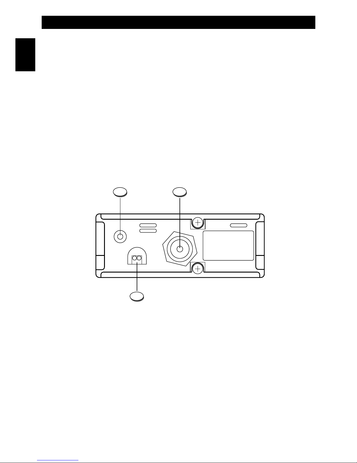
Rear Panel
11. EXT (External Speaker) Jack
This jack is for connecting an external speaker (optional).
12. ANTENNA Connector
Antenna connector. Refer to the sections INSTALLATION OF THE ANTENNA and INSTALLING AND CONNECTING
THE MOBILE ANTENNA WITH MAGNET BASE.
13. 13.2VDC POWER CORD
13.2VDC power cord input.
FULL KIT VERSION
The power cord is complete with lighter adaptor plug and fuse.
EXT
DC
13.2V
11
13
ANT
12
8. SQL Control (Squelch adjustement)
The SQUELCH control allows to silent the receiver by cutting the background noise, when no signals are received. Turn
the knob clockwise until the background noise is cut. Turn the knob counter clockwise (SQUELCH opening) in order to
listen to the weakest signals.
9. VOL/OFF (OFF/Volume) Control
Use this knob to switch radio ON and OFF, as well as to adjust the receiver volume to the desired level. To adjust the
receiver volume in case no signals are received on the operating channel, open the SQUELCH and then adjust the
receiver volume using the background noise as a reference.
10. Microphone Connector
Connect the microphone to this connector and turn the connector ring to lock it.
Controls, Indicators and operation
English
Controls and operation
- 5 -
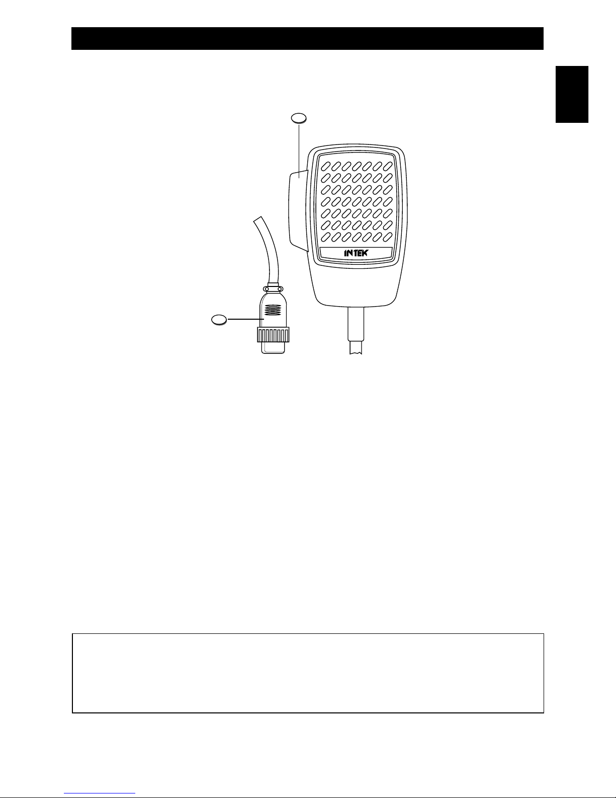
Microphone
14. PTT (Push-to-Talk) Key
Transmitter key. Press the PTT key (14) to transmit and release it to return to the receive mode.
15. MICROPHONE Plug
4-pin microphone connector with locking ring. Connect it to the microphone connector on the front panel of the radio.
14
15
IMPORTANT !
Do never attempt to open the cabinet of the transceiver. No user serviceable parts inside. Internal modifications or
tampering may cause damage to the product, modify its technical specifications and will void warranty rights. If
service or repair are required, please go to an authorised service centre or specialized technician.
English

Installation
- 6 -
Installation
Before installing the main unit in the vehicle, check and select the most convenient location, in order that the radio will be
easy to reach and comfortable to operate, without disturbing or interfering with the vehicle drive. Use the supplied
bracket and hardware to install the radio. The bracket screws must be well tightened in order not to become loosen with
the vehicle vibrations. The car mounting bracket can be installed over or below the radio and the radio may be inclined
as desired according to the specific type of installation (under dashboard or track cabin roof installation).
Installation of the Main Unit
Before connecting the radio to the vehicle electric system, make sure that radio is switched off, with the VOL/OFF (9) knob
completely turned counter clockwise at OFF position. The DC power cable (13) of the radio is complete with a fuse holder
with fuse located on the red positive (+) wire. Connect the DC power cable to the vehicle electric system, with special
attention to respect correct polarity, even if the radio is protected against polarity inversion. Connect the red wire to the
positive (+) pole and the black wire to the negative (-) pole of the vehicle electric system. Make sure that the wires and
terminals are firmly and stably connected, in order to prevent cables from disconnecting or causing short circuits.
FULL KIT VERSION
Connect the lighter adaptor plug (13) to the 12VDC socket of the vehicle. Fuse is located inside the lighter adaptor plug.
To replace the fuse unscrew the cap of the plug, remove the fuse and the spring then reinstall all parts by first inserting
the spring and then the new fuse.
Installation of the Antenna
A specific mobile antenna adjusted for 27 MHz frequency range must be used. The antenna installation must be done by
a specialised technician or service centre. Please pay special attention to carefully install the antenna on the vehicle with
perfect connection to ground. Before connecting the antenna to the radio, it is necessary to check the correct operation
of the antenna with low standing wave ratio (S.W.R.), using adequate instruments. If not, the transmitter circuit of the
radio could be damaged. The antenna must be usually installed on the highest part of the vehicle, free from obstacles
and as far away as possible from any source of electric or electromagnetic noise. The RF antenna coaxial cable must
not be damaged or pressed on its way between antenna and the radio. The correct operation of the antenna and the low
standing wave ratio (S.W.R.) must be checked periodically. Connect the RF antenna coaxial cable to the antenna
connector (12), located on the rear side of the radio.
Checking Operation of the Radio
Once radio has been connected to the vehicle electric system and to the antenna, the correct operation of the system
may be checked. Please proceed as follows :
1) Check that the power cable is correctly connected.
FULL KIT VERSION
Check that power cord is correctly connected and that the lighter adaptor plug is correctly inserted in the 12VDC
socket of the vehicle.
2) Check that the RF antenna coaxial cable is correctly connected.
3) Connect the microphone to the connector (10), located on the front side of the radio.
4) Rotate the SQL knob (8) counter clockwise.
5) Turn radio on using the VOL/OFF knob (9) and adjust volume to the desired level.
6) Select the desired channel, using the channel selector keys (5, 6).
7) Rotate the SQL knob (8) clockwise, to cut the background noise.
8) Press the PTT key (14) to transmit and release it to receive.
The transceiver will work correctly.
English
Installing and connecting the mobile antenna with magnet base
FULL KIT VERSION
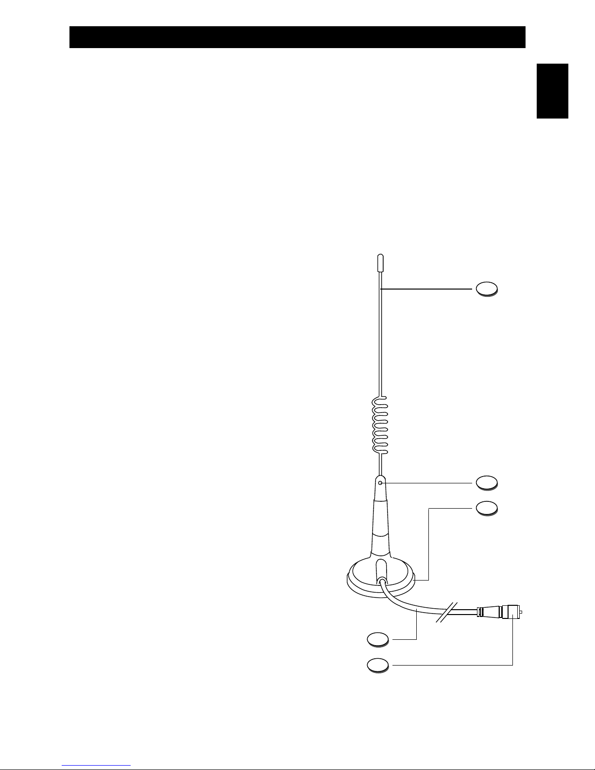
Installing and connecting the mobile antenna with magnet base
A 27 MHz mobile antenna with magnet base and 4m RG-58/U is included in the kit. Connect the whip (A) to the magnet
base and tighten the locking screw (B) using the supplied tool. Please pay attention to correctly placing the magnet
antenna on the vehicle top. The magnet antenna must be firmly attached to the vehicle metal body. Connect the antenna
connector (E) to the antenna outlet (12) located on the rear side of the radio. Before turning on and operating the radio,
the correct performance of the antenna (S.W.R. ratio) must be check with an S.W.R. meter. If necessary, adjust the
length of the whip (A) until a correct S.W.R. ratio is reached. Otherwise the transmitter circuit of the radio might be
damaged. Antenna must be usually placed on the highest part of the vehicle, free from nearby metal parts and as far as
possible from any possible source of electric or electromagnetic noice. The antenna cable must not be damaged in its
way to the radio.
Parts description
A. Whip
Steel whip with protective rubber cup.
B. Locking screw
Locking screw for adjusting and tightening the antenna
whip, using the supplied tool.
C. Magnet base
Antenna magnet base to be placed on any iron or steel
surface, with no need to drill any hole on the vehicle body.
D. RG-58/U Cable
RG-58/U cable, 4m long.
E. RF Connector
PL-259 connector.
Connect to the antenna outlet (12), located on the rear side
of the radio.
Warning ! Before turning on and operating radio,
make sure that the connector (E) is correctly
connected to the antenna outlet (12) located on the
rear side of the radio.
A
B
D
E
C
- 7 -
English
Frequency bands table - User Information
- 8 -
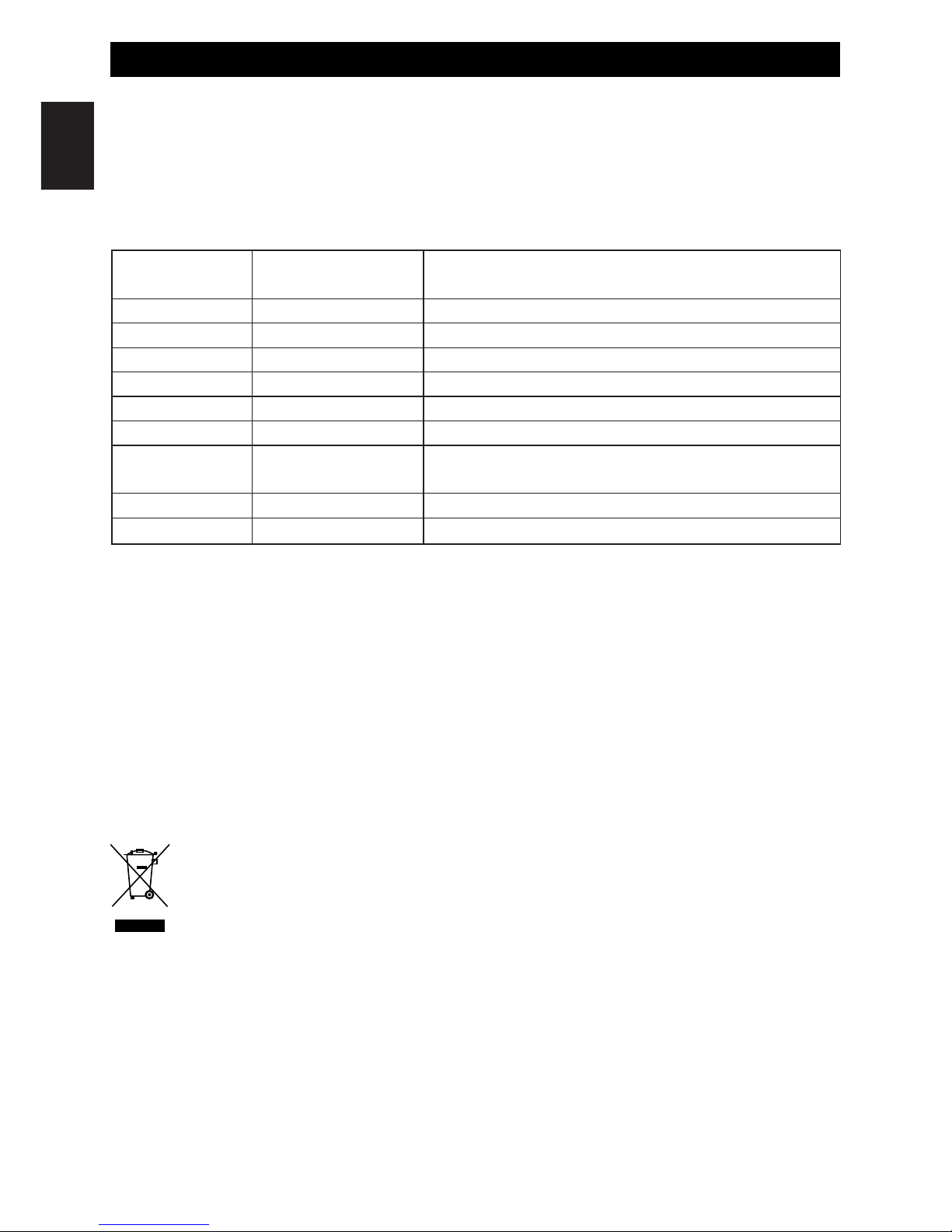
Frequency Bands Table
The transceiver INTEK M-100 PLUS includes an advanced multi-standard programmable circuit, which allows to
program different frequency bands, specifications and operating modes, in conformity with the regulations in the country
where the product is used. 9 programmable frequency bands are available, as per the below table :
Attention ! This radio has been factory pre-programmed on the CE frequency band (CEPT 40CH FM 4W), since this
standard is currently accepted in all the European countries. Please refer to the information table at page I (Restrictions
on the use of CB transceivers).
User Information
in accordance with art. 13 of the Legislative Decree of 25th July 2005, no. 15 ”Implementation of Directives 2002/95/EC,
2002/96/EC and 2003/108/EC, relative to reduction of the use of hazardous substances in electrical and electronic
equipment, in addition to waste disposal”.
The crossed bin symbol shown on the equipment indicates that at the end of its working life the product must
be collected separately from other waste.
The user must therefore take the above equipment to the appropriate differentiated collection centres for
electronic and electro technical waste, or return it to the dealer when purchasing a new appliance of
equivalent type, in a ratio of one to one.
Appropriate differentiated waste collection for subsequent recycling, treatment and environment-friendly disposal of the
discarded equipment helps to prevent possible negative environmental and health effects and encourages recycling of
the component materials of the equipment.
Illegal disposal of the product by the user will be punished by application of the administrative fines provided for by the
legislative decree no. 22/1997 (article 50 and following of the legislative decree no. 22/1997).
FREQUENCY BAND
ID CODE
COUNTRY
SPECIFICATIONS
(Channels, Operating Modes, TX Power)
E1 ITALY/SPAIN
40CH AM / FM 4W
I2 ITALY
36CH AM / FM 4W
dE GERMANY
80CH FM 4W - 12CH AM 1W
d2 GERMANY
40CH FM 4W - 12CH AM 1W
EU EUROPE/FRANCE
40CH FM 4W - 40CH AM 1W
CE CEPT
40CH FM 4W
UUK
40CH FM 4W UK FREQUENCIES
40CH FM 4W CEPT FREQUENCIES
PL
PD
POLAND
POLAND
40CH AM / FM 4W POLISH FREQUENCIES
40CH AM 1W / FM 4W POLISH FREQUENCIES
English
 Loading...