

Page 1
KT-355Ek
‘:
VHF FM HANDHELD’TRANSCEIVER
1
RICETRASMETTITORE VHF FM
1
PORTATILE
!
IINSTRUCTION
MANUAL
MANUALE DI ISTRUZIONI
(versione lingua inglese)
Page 2
Page 3
Before
USing
fhe Unit
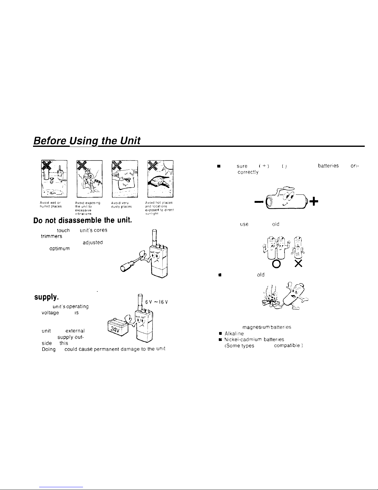
(Observe the Following Precautions)
n Never
tauch
the unit’s cores or
trimmers
They are already adjusted
for
Optimum
Performance
The unit will not operate
on a 24 V power
suPPlY-
n The unit’s operatlng
voltage range 1s 6 0
. 160V
Never connect the
unit to an extemal
power supply
out-
side of this range
Doing
so
could Cause
- 16V
unit
Batteries
H
Make sure the j + ; and / ) ends of the battertes are ori-
ented correc!ly
n Never
use
new and
old
batteries together
9
Never expose
old
batteries to an open flame
Suitable batteries
n SUM-3 magnestum batterles
H
AlkalIne batteries
E
Nickel-cadmium batterles
(Same
types are not compatible
1
2
Page 4
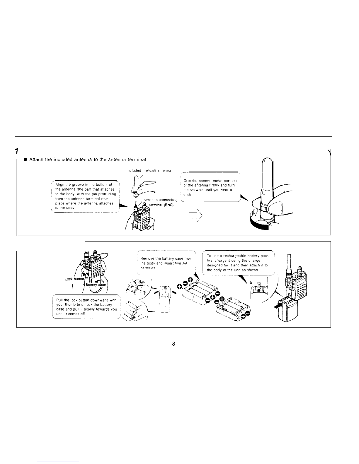
Setup
7
Attaching the antenna
2 Battery insertion
.
Page 5
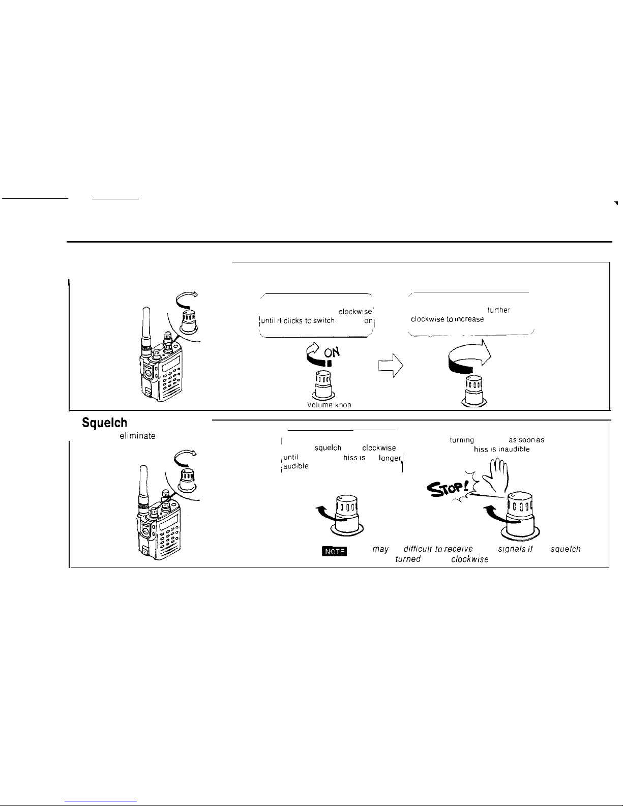
3 Switching power on and
1
adjusting the volume
/
‘,
1’
Turn the volume knob
clockwlse’
Turn the volume knob
further
Tuntöl
it
cllcks
to
swltch
power
on,
clockwse
to
~ncrease
the volume
4
Squelch
adjustment
, n How to
eliminate
background
‘Turn the
squelch
knob
clockwlse
iunt~l background
hiss 1s
no
longerl
,audible
I
Stop
turning
the knob as
soo” as
background
hiss IS inaudible
m
It may be difhcult to
recerve
weak sfgnals ff the squelch
knob is turned too far
clockwfse
4
Page 6
5
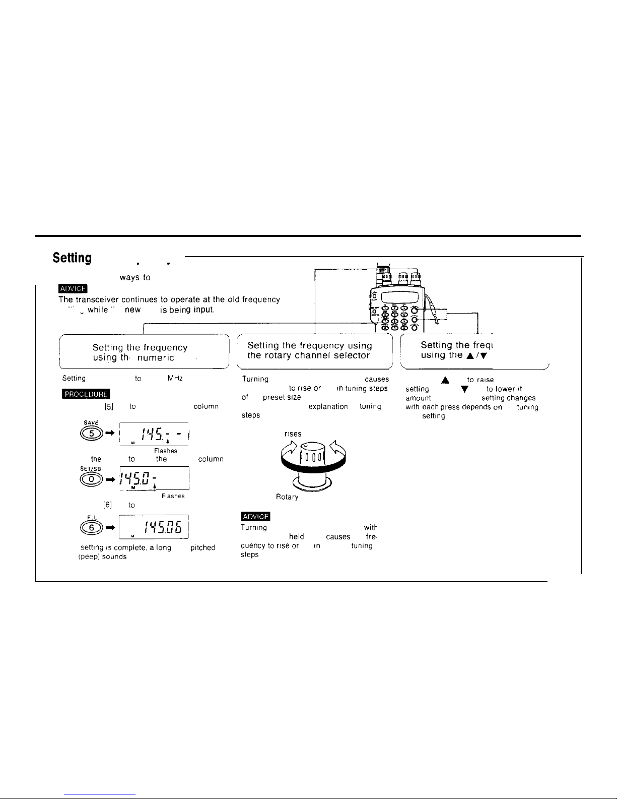
Settinn
the frequencv
n There are three
ways to
set the frequency
setting
while
the
new
one
IS
bein
e
numeric
keys
uency
keys
Setting the frequency to 145.06 MHz
1) Press the
151
key to Input the 1 MHz column
SAVE
a-j
u 111’5.; - !
Flashes
2) Press
the
[0] key to Input the 100 kHz
colum”
SET/%
a-i
1
:95.E?
j
Y
FI%hEZ
3) Press the
[6]
key to Input the 10 kHz column
When
settlng is
compiete. a
lang high pltched
beep (peep) Sounds
Turmng the rotary channel selector
causes
the frequency to
rise or
fall m tuning steps
of the
preset size
See page 46 for an explanat~on of tumng
Steps
Frequency r!ses
Frequency falls
Rotary channel selector
Turnlng the rotary channel selector
wth
the FUNC key held down
causes
the fre-
quency to
rise or
fall I” 100 kHz tumng
Steps
Press the A key to
rase
the frequency
setting and the V key to
lower It
The
amount the frequency settlng changes
wth
each press depends on the tuning
step
sett1ng
5
Page 7
6
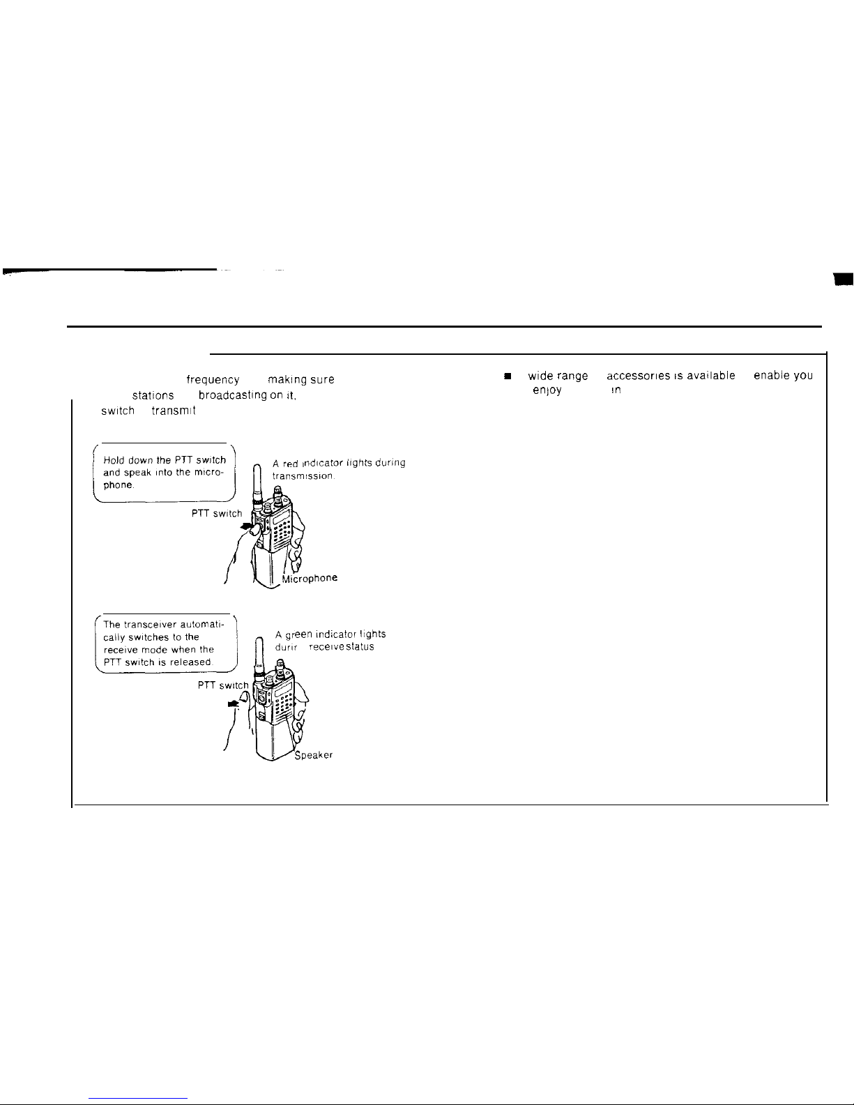
Transmitting
. After setting the frequency and making sure that no
other statlons are broadcastlng on
It.
press the PTT
switch
to transmIt
.
H
A wide range of accessorles 1s avatlable to enable
you
to enjoy the unit an many different ways.
nducafor hghts during
een Indicator Itghts
g
recelve Status
6
Page 8
Functions
and
ODeration
1.
Terminology
3
1
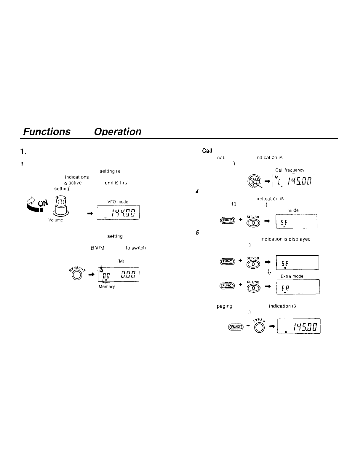
VFO mode
In the VFO mode the frequency settlng IS displayed and the
M, C and DUAL Indlcations are not displayed
The VFO mode IS actlve when the
untt 1s
flrst turned on
(the factory
setting)
Vorurne
knob
2 Memory mode
In the memory mode the frequency settlng and the memory
address number are displayed.
In the VFO mode, press the B VIM ENT key to swltch to the
memory mode. (See pages 29-33 )
5
Memory
(M)
Me’mory
address number
6
Paging mode
Cal1
mode
In the
cal1
mode the C indication IS displayed
(See page 40
)
Carl IrequUlcy
@*pqyq
Set mode
In the set mode the SE Indlcatlon IS displayed
(See pages 10 and 48-50
.)
Set
mode
Extra mode
In the extra mode the EA Indlcatlon IS dlsplayed
(See pages 54-55
)
Set mode
In the paglng mode the PAG Indication 1s displayed
(See pages 21-26
.)
7
Page 9
2.
1)
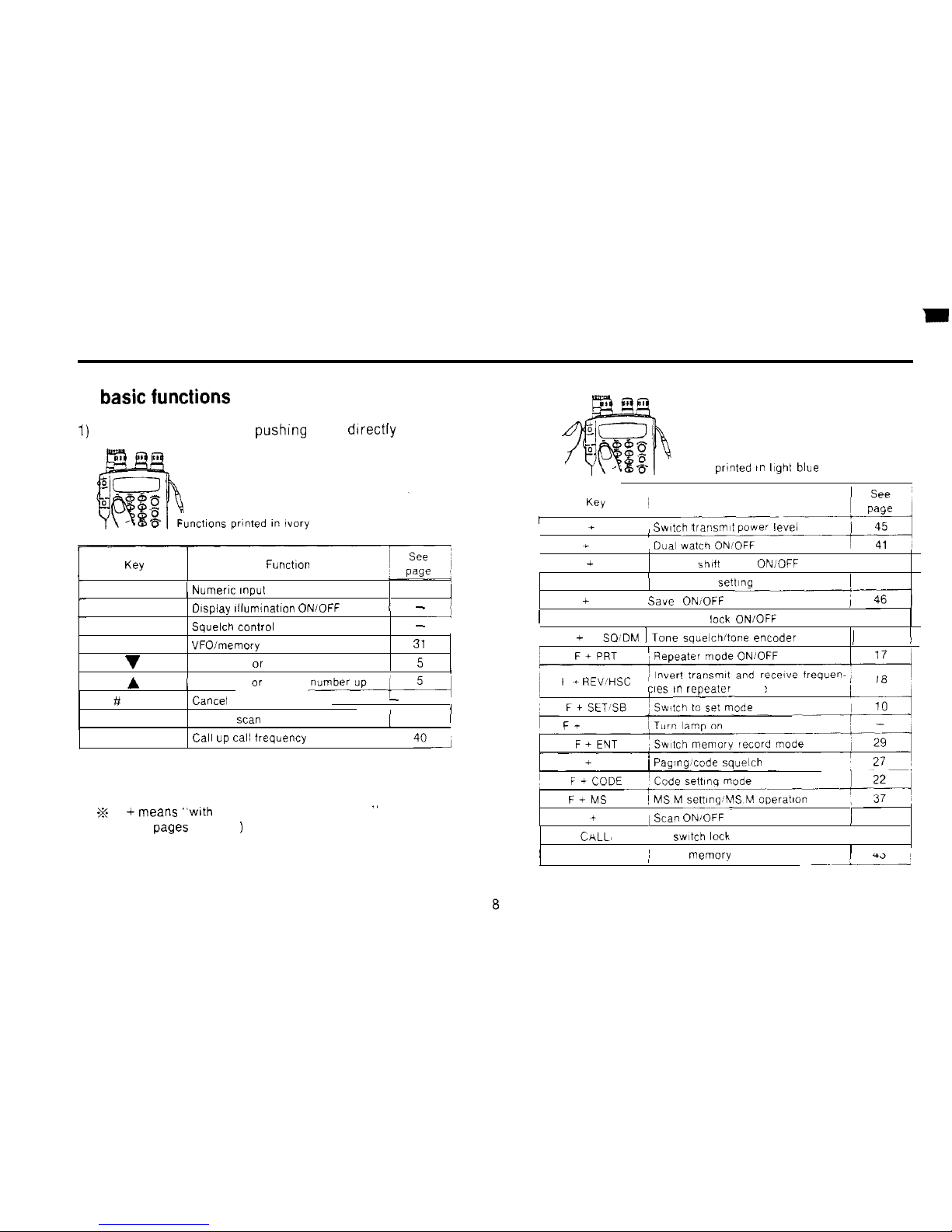
basic functions
Functions accessed by pushlng keys
directly
l-3
QY
Function
O-Q
1 Numeric
Input 1 5
1
LAMP 01splay
illumination
ONIOFF
l -
1
SQL OFF Squelch
control
ONIOFF
-
VIM
VFOimemory
mode toggle
31
v
Frequency or address number down,
5
/
A
(
Frequency or address
#
CL PS
Cancel mode
1
MS
Memory scan ON/OFF
(
36
l
CALL
Cal1 up ca11 frequency
,
401
2) Functions accessed by holding down the FUNC key
and pressing another key
.x F +
means “wth
the FUNC key held down
”
(See pages 45-47
)
Functions printed
it. hght
blue
I
F * PO
F + DUAL
/ Dua, ,,,,,:L-
-=
Switch
tral-ismt
power
level
F + SFT Memory shltt mode ONIOFF
33
F + STEP
I
Tuning step settlng
1 46
_--M-
F + SAVE
Save
ONfOFF
l
F+F L Frequency leck ON/OFF
47
F + T SQIDM 1 Tone
squelchitone encoder
toggle
)
28
)
F + REV,HSC
cies ,n
repeater
mode
~-.
Ft
L LAMP
F + PAG
i
Paging,code squelch ONIOFF
F+MS
M
F + PS
i
Scan
ONIOFF-
I
35
F +
C&LL>
P L
PTT
swtch
leck ON OFF
47
~ F+ DTMF MI DTMF
memory
mode
’
43
i
~~ 1-
Page 10
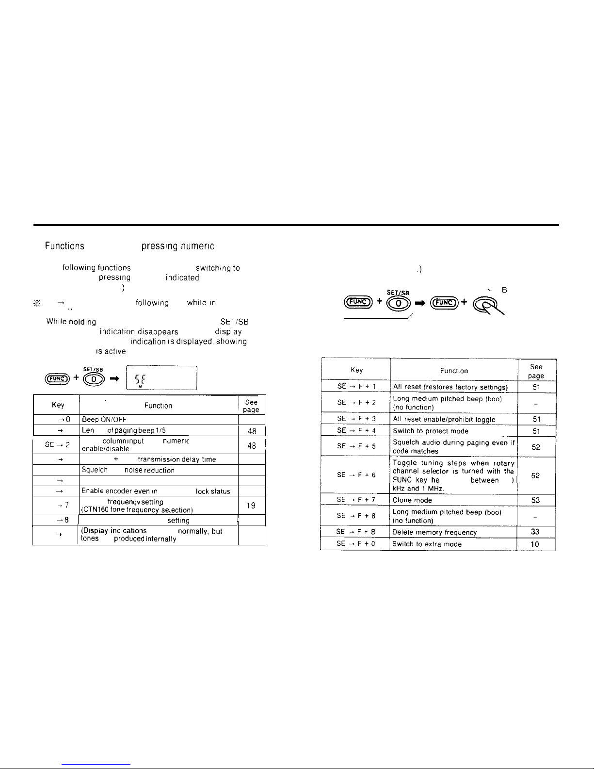
3) Functions accessed by
presslng numeric
keys in the
set mode.
The following functions are accessed by switching to the
set mode and presslng the keys Indlcated
(See pages 48-50
)
z
SE + means “press the following key while an the set
mode
”
n
While
holding down the FUNC key. press the 0
SET/%
key
The frequency
Indicatton
dlsappears from the display
The [SE] (SET MODE) indication IS displayed. showing that
the set mode 1s actlve
K~Y
, v-Y*
SE +
0
Beep ONIOFF
1
48
SE + 1
Leil
gth of
paglng beep
li5 toggle
l 48 1
cc 1
/
1 kHz
column input
from
nuneric
YL - L
: keys
enableidisable
toggle
48
j
SE + 3
Repeater + PAG
transmissmn delay time
49
SE -4
Squelch
pop
no~se reductlon
49
SE + 5
APO (Auto Power Off) ONIOFF
49
SE - 6
Enabie encoder even ,n
frequency
leck status
50
SE
+7
CTCSS
frequencv settIna
mode
(CTN160 tone frequency-selectlon)
.n
IY
SE +
8
1
Repeater offset frequency
settlng
/
19
SE + 9
(Display mdlcations
appear
normally. but
no
tones
are
produced Internally
)
4) Functions accessed in the set mode by holding
down the FUNC key and pressing another key.
(See pages 51-53
.)
SETISB
0. 1. 3- 9 EJ keys
~+~+~+Qq
\
/
Set mode
channel sele lurned wlth th
Id down
between
100
9
Page 11
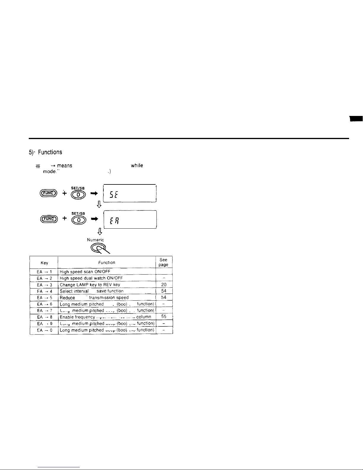
5). Functions
accessed by pressing keys in the extra
mode
s
EA +
means
“press the following key
whlle
in the extra
mode.”
(See pages 54-55
.)
Set mode
i
Extra mode
Numeric key
R
Select mterval for save
functlon
Reduce DTMF transmlsslon
Speed
Gong
medium
pltched
beep
(boo)
(no
functlon)
Long medlum
pitched
beep
(boo)
(no
functlon)
Enable
frequency Input from 100 MHz
column
Long medium
pitched
beep
(boo)
(no
tunctmn)
Lang
medlum
pltched
beep
(boo)
(no
functlon)
10
Page 12
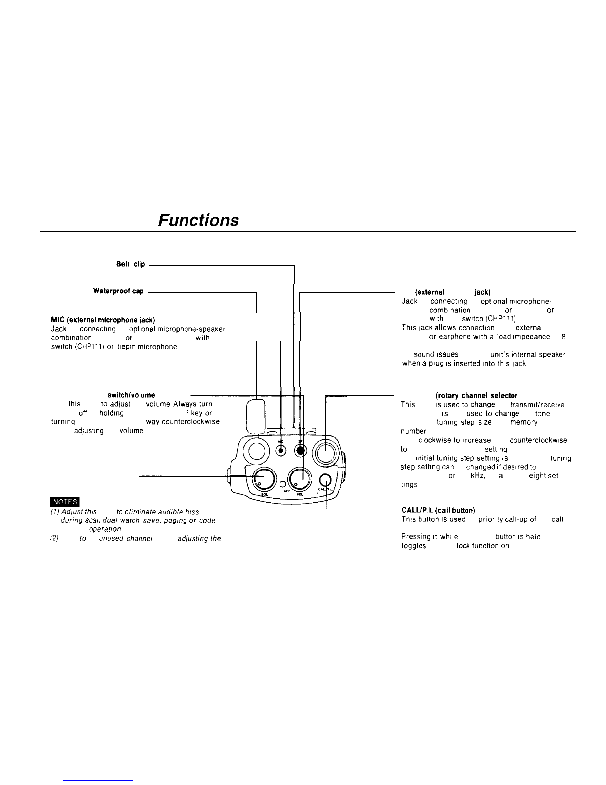
Operation and Functions of Parts
Top View
Be” c’ip I
Waterproolcap .I
MIC
(extemal
microphone jack)
Jack for connectlng an Optional
mlcrophone-speaker
1
//
combmatlon
(CMP111 or CMP115). headset
wth
PTT
swltch
(CHPlll) or
tlepm mtcrophone (CMP113)
SP
(extemal
speaker
jack)
Jack for connectmg an
optional
rmcrophone-
speaker
comblnatlon
(CMP111 or CMP115)
or
headset with PTT
swtch (CHPlll)
This
jack allows connectlon
of an
extemal
speaker or earphone
wth
a
Load impedance
of
8
ohms
No
wund 6s”es
from the
“nlt’s mternal speaket
when a plug IS
inserted
into this ]ack
VOLUME (power
switch/volume
knob)
Turn this knob to adlust the
volume Alwa
squelch off by holdlng down the SQL OFF
turning the SQL knob all the
way counterc
before adfustmg the
volume
SQL (squelch knob)
CHANNEL
(rotary channel selector
knob)
Thls knob IS used to
Change
the
transmrt/recewe
frequency It IS also used to
Change
the tone
frequency, tunmg
Step size
and
memory
address
number
Turn
clockwse to
~ncrease, and
counterciockwse
to
reduce, the frequency settlng
The
mitial
tunmg step settlng IS 10 kHz The tunmg
step setbng
tan
be changed 11
deslred to
5. 12 5.
20. 25. 50, 75 or 100
kHz,
for a total of
eight
set-
t1ngs
(7) Adpsf
fhis hnob to
ellmmate
audlble
h1.w
durmg
scan
dual
watch.
SBYB, pag,ng or
Code
squelch
operafron.
(2)
Tune IO an
unused channei
before
ad/usfmg
fhe
squelch
CALL/P.L (cal1
buiton)
This button IS used for
prlortty
call-up of the
cal1
frequency
Presslng It while the FUNC button IS held down
toggles the PTT leck functlon on and off
11
Page 13
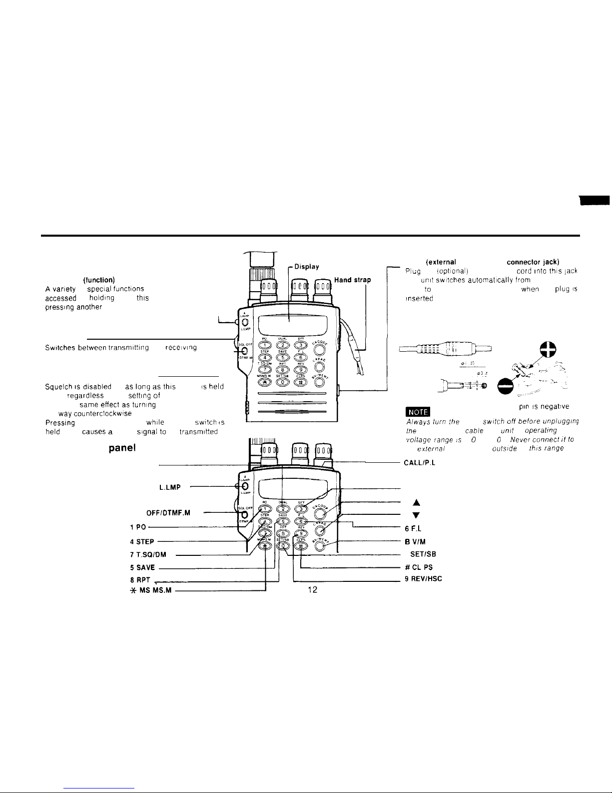
Front View
FUNCTION (function)
A vamty
of
special
functlons ca” be
accessed by holding down this key and
press,ng another key
1
PTT switch
Swtches
between
transmlttlng
and
recelwng
SQL OFF (squelch oll button)
Squelch IS dlsabled for as lang as this button is held
down,
regardless
of the sett,ng of the squelch knob
lt has the same effect as turning the squelch knob all
the way
counterclockwise
Presslng the SQL OFF button while the PTT
switch
is
held down causes a DTMF
signal to
be
transmltted
Front control
Panel
(keys)
2 DUAL
A LAMP L.LMP
SQL
0FFIDTMF.M
_
DC IN
(extemal
power supply connector jack)
Plug
the lopt~onal) power supply
Cord ~nto
thls
jack
The umt swltches automat~cally fram the battery
pack to the extern.3 power supply when the
plug is
‘nserted
m
Center
pl” is
negative
Aiways
turn :he power
swltch
off
before
unpiugging
he
power supply cable Jhe
unit
s
operaling
Vollage
range :.5
6 0 ,
16 0 V
Neer connect 11 10
an
exlernai
power supply
oufside
of Ibis
range
CALL1P.L
3 SFT
D A CODE
C V PAG
6 F.L
B
V/M ENT
0 SETISB
Page 14
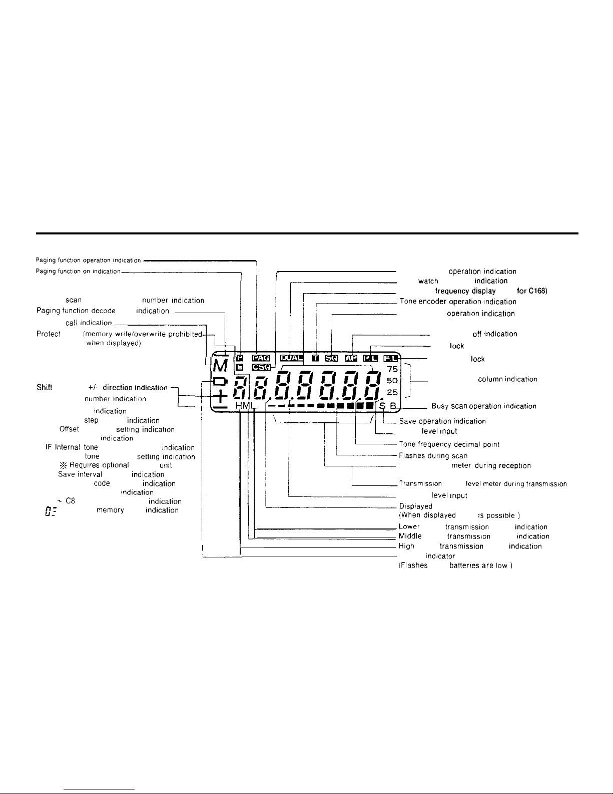
Memory scan memory address nurnber rndication
Paglng
funct~on
decode mark rndrcation
Protect mode
jmemory writeloverwrlte
prohtbrted
Memory
cal1 tm~k~i_,,,,,1~~
Shift frequency
+/- direction
rndicatton
Code address number mdrcatron
l--
L
SE Set mode Indrcatron
CH Tuning
Step
settrng rndrcatron
OF Offset frequency sethng rndrcatron
EA Extra mode rndicatron
IF
Internal tone frequency settrng
indication
CF CTCSS tone frequency setttng rndication
% Flequires optronal CTCSS unit
SA Save
~nterval
settrng rndrcatron
CP Individual code address rndrcatron
C Code settrng mode indrcatron
CO- C6 + CP Code address rndrcatron
il u :
DTMF memory block rndrcation
Code squelch
operahon
rndrcatron
l
L
Dual
watch
Operation
mdication
UHF band
irequency display
(VHF
ior
C166)
Tome encoder operahon
rndrcahon
Tone squelch operatron rndrcatron
Auto power off
indicatron
PTT leck indication
Frequency leck indication
1 kHz/100 Hz column indrcatron
Busy scan
operabon
rndrcatron
Save operatron
mdrcatron
1 kHz
level
Input enabled
Signal strength
meter
during receptron
Transmlssron output level meter during fransmss~on
100 MHz
level rnput
enabled
Drsplayed when all reset enabled
(When drsplayed reset rs
powble )
Lower
power transmrssron output rndication
Mrddle power transmrssron output mdrcahon
High power
transmission
output rndrcatron
‘-
Battery rndrcator
(Flashes when batterres
arc
low
)
13
Page 15
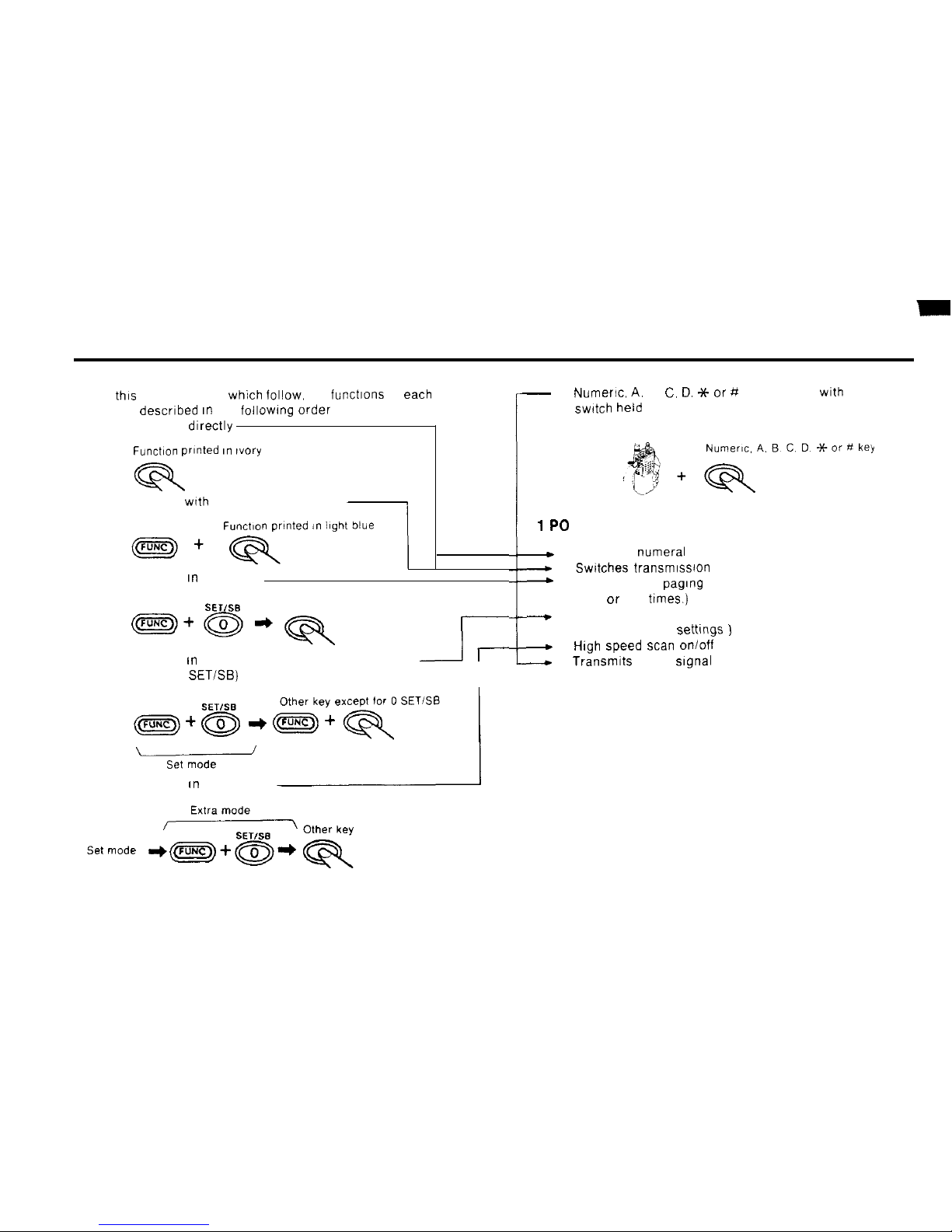
n On
thts
and the pages
which
follow, the functions of
each
key are descrrbed rn the foilowtng
Order
1) Key pressed drrectly
Function
printed I” ~vory
2) Key pressed
wrth
FUNC key held down
Function prlnted
,n
3) Key pressed rn set mode
SET/SB
Other key
m+@*q
4) Key pressed tn set mode with FUNC key held down
J-
(except for 0
SETISB)
r
w
5) Key pressed
fn
extra mode
:
-
6)
Numeric, A.
B, C. D.
Jt- or
# key pressed
wth
PTT
swdch held
down
1PO
+
1) Inputs the numeral 1
-
2) Swttches transmrssron output
+
3) Sets length of pagtng beep
(one or five
trmes.)
--.
4) All reset.
(restores factory settmgs
)
4
5)
High Speed scan
on/off
-.-.+
6) Transmtts DTMF
Signal
1
14
Page 16
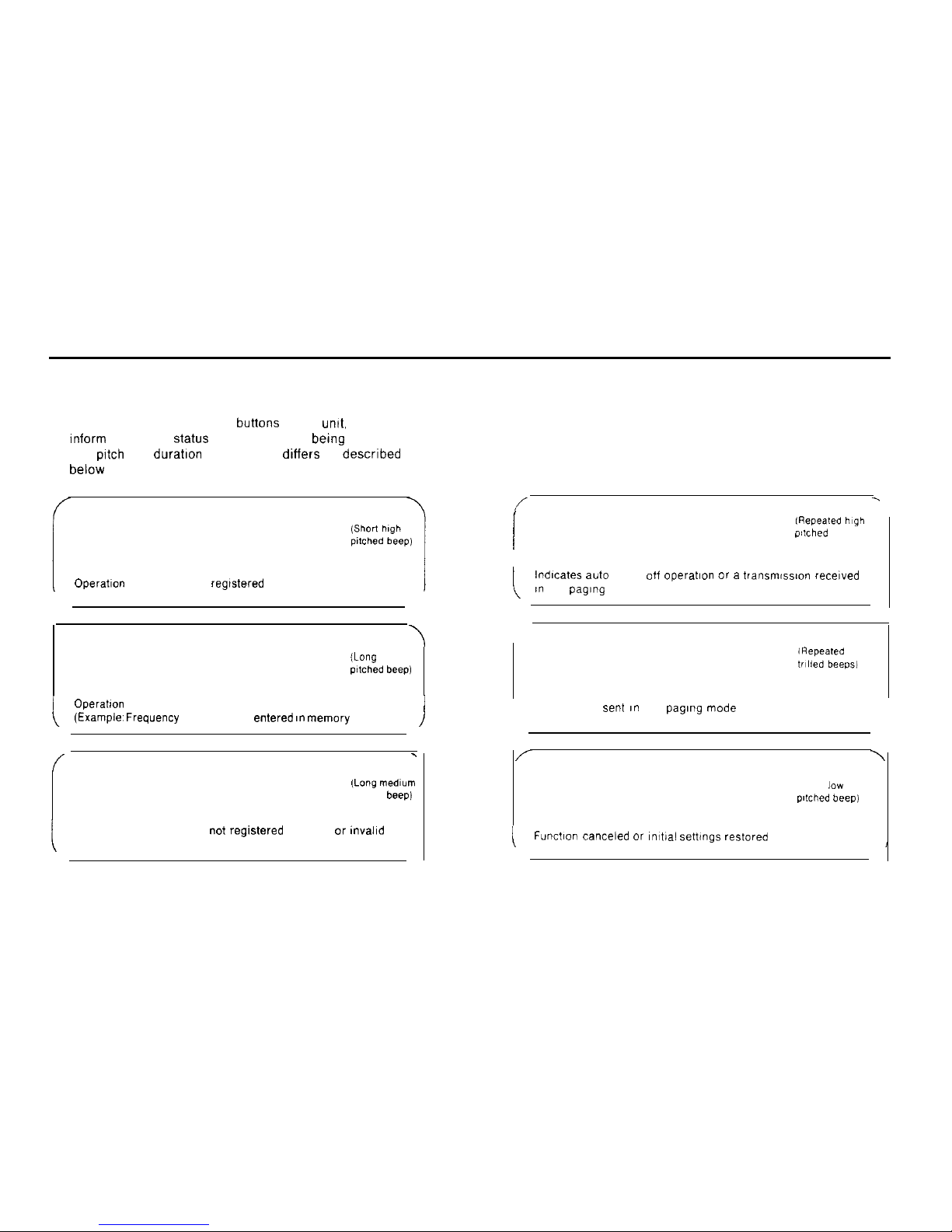
Beep indications
When you press the control buttons of the
unit,
beeps
inform you of the
Status
of the Operation being performed
The
pftch
and durahon of the beeps dlffers as descrlbed
below
Pip
Operation
button pressed
regtstered
correctly
Peep
\
(Lang high
pltched beep)
Operation
successfully completed.
(Exampk Frequency
successfully
entered In memory
)
/
.
Boo
(Lang medlum
pltched
beep)
Operation button pressed
not reglstered
correctly or
mvalld
button pressed.
/
Pip-pip-pip-pip
lhpeated high
pltched beeps,
!
Indlcates auto power otf
operation or a transmtswx recelved
an
the paging mode
Pilala-pilala-pilala
Transmission sent an the paglng mode
/
\
Puff
\
Wort
lOW
pltched beep,
Functlon
canceled or mtial
settmgs
reatored
I
15
Page 17
Repea ter Operation
n About repeater Operation
n Conventional Operation
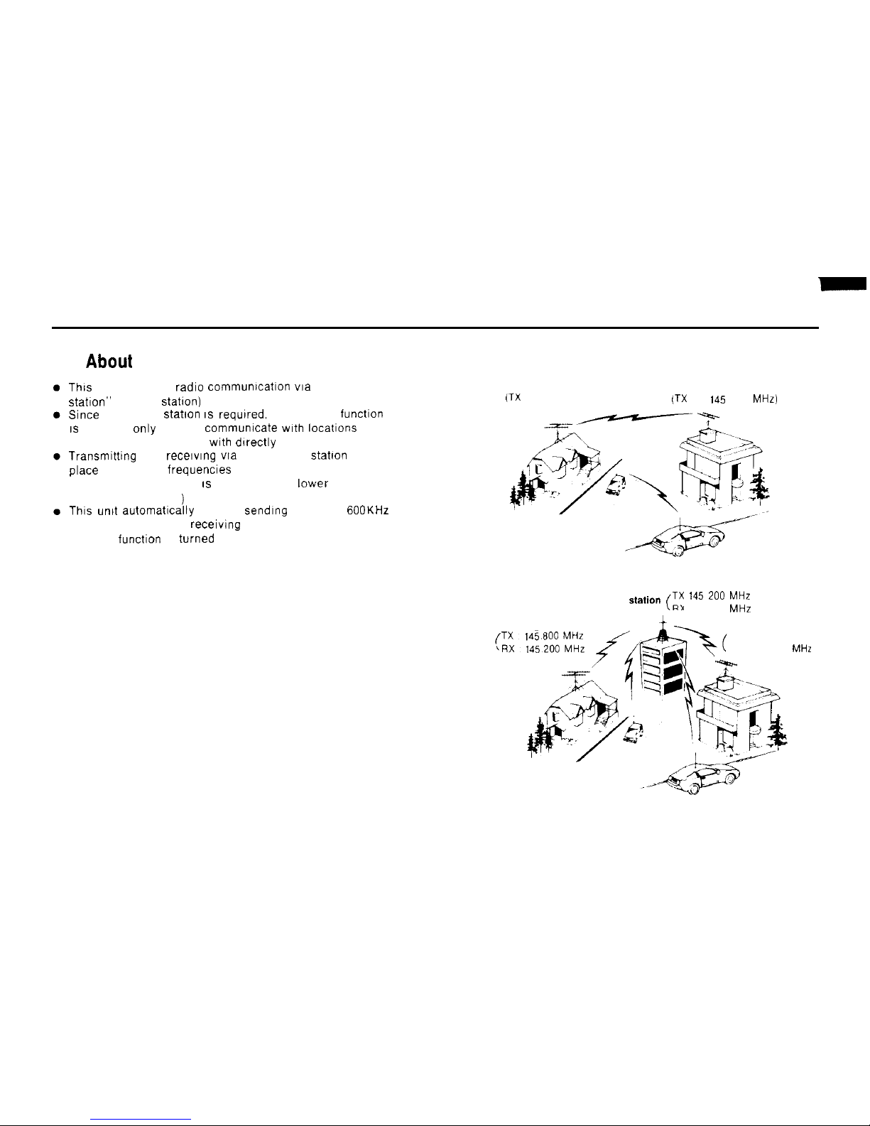
This
term refers to radle communication
via
a ‘repeater
statlon”
(a relay Statton)
Since
a repeater Station IS
requlred,
the repeater function
IS
generally only used to
communxate wth locations
too
far away to communicate
wth dlrectly
Transmittang
and receiving
via
the repeater
statlon
takes
place on different
frequencles
(The sending frequency IS 600 KHz (VHF),
lower
than the
receiving frequency
)
This
unit automatically sets the
sending
frequency GOOKHz
(VHF). lower than the receiving frequency when the
repeater functlon is
turned
on.
(TX
RX 145 240 MHz)
(TX RX
145
240
MHz)
n
Repeater Operation
Repeater station
(Tx 145
‘O” MHz
RX 1451800 MHz
TX 145 800 MHz
RX 145 200
MHz
16
Page 18
Repeater Operation
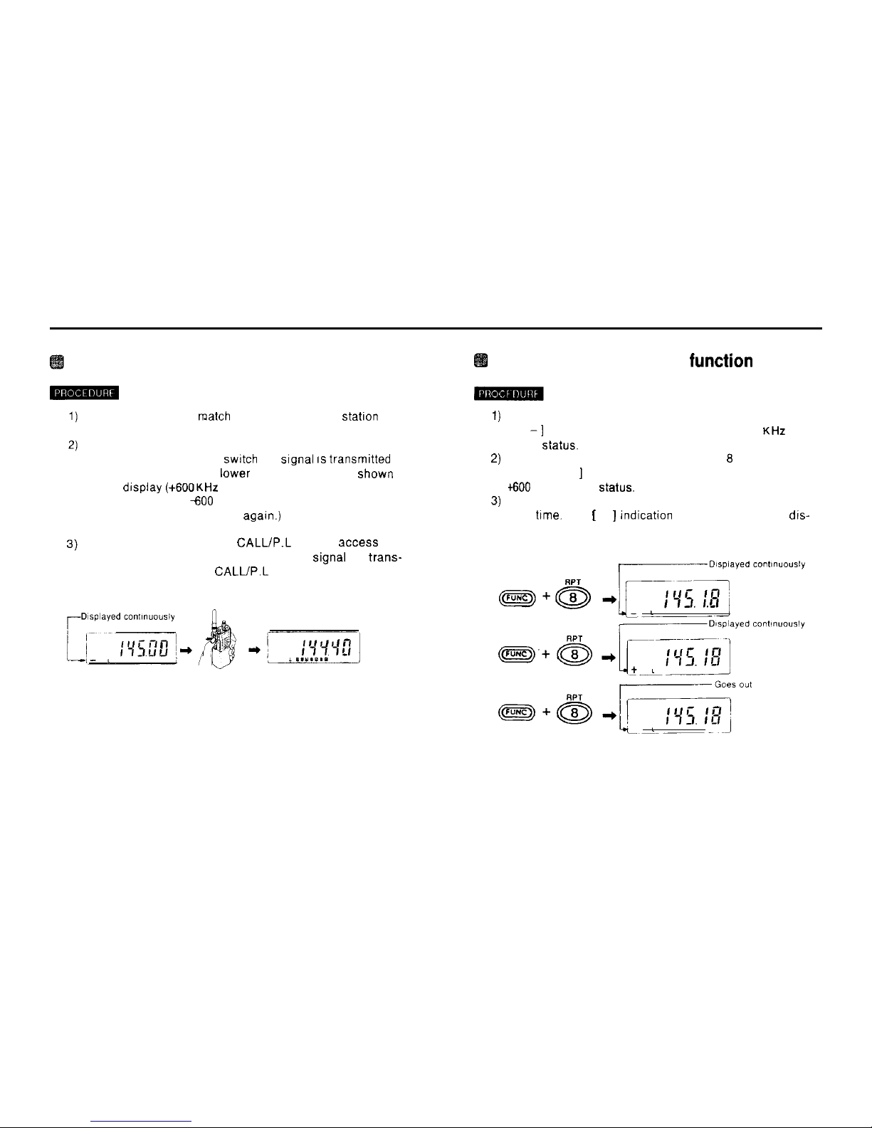
Canceling the repeater
function
Set the frequency to
match
that of the repeater
Station
1)
Hold down the FUNC key and press the 6 RPT key
When you press the PTT
swrtch
the
Signal IS
transmrtted
at a frequency -600 KHz lower than the frequency shown
on the drsplay
(+600KHz
offset).
(To transmit with a
600
KHz offset, hold down the FUNC
key and press the 8 RPT key
agarn.)
2)
3)
While transmitting, press
CALL/P.L
key to access the
repeater Station. (The 1.750 KHz burst Signal is
trans-
mitted only while the
CALL/P.L
key is depressed.)
Hold down the FUNC key and press the 8 RPT key.
A [ -1 appears on the display. indicating -600
KHZ
offset
Status.
Hold down the FUNC key and press the 6 RPT key once
again. A [ + ] appears on the display, indicating
dO0
KHz offset
Status.
Hold down the FUNC key and press the 8 RPT key a
third
ttme.
The [ + ] indication disappears from the dis-
play and the repeater mode is canceled.
17
Page 19
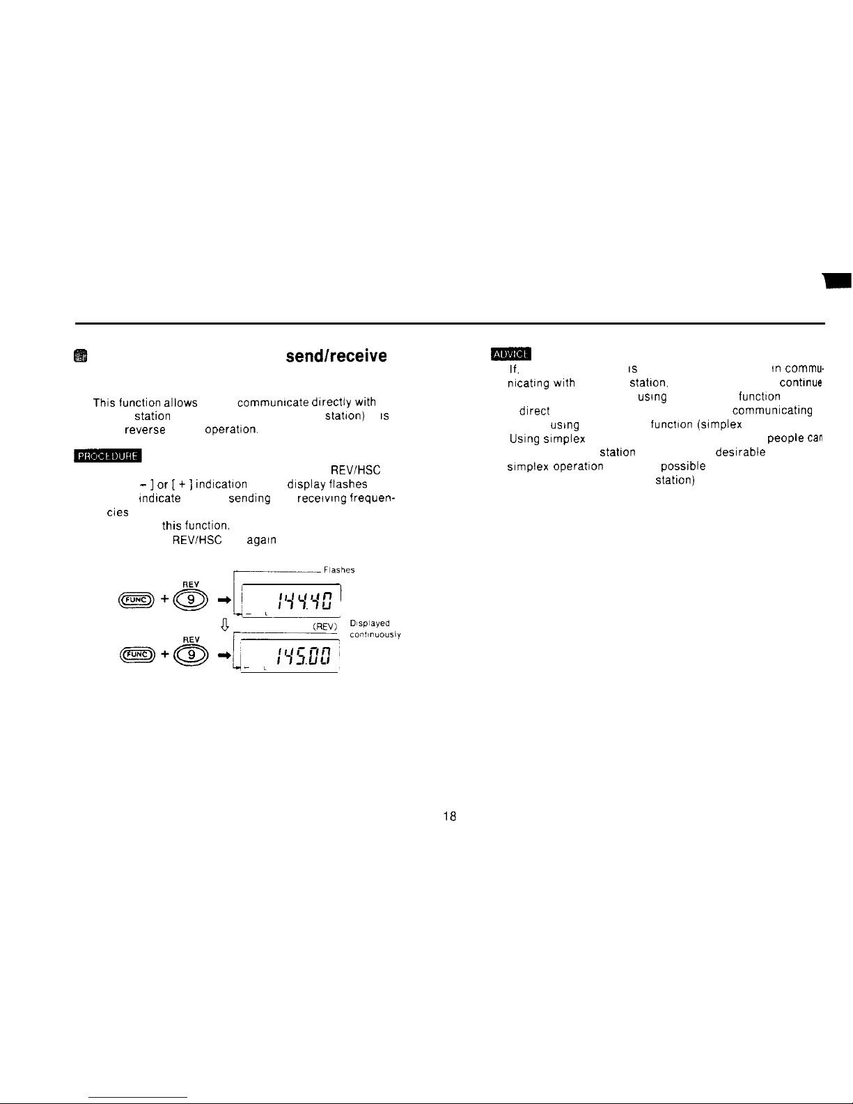
Reversing the repeater sendlreceive
frequencies
n
Thrs
function allows you to communrcate drrectly
wrth
another
Station
(wrthout using the repeater
Station)
It
IS
called reverse (REV) operahon.
1) Hold down the FUNC key and press the 9
REV/HSC
key
The [ - ] or [ + ]
rndrcatron
on the drsplay flashes on and
off to
rndrcate
that the sendrng and recervrng frequen-
cies have been reversed
2) To cancel
thrs functron,
hold down the FUNC key and
press the 9
REVIHSC
key
agarn
(1)
If.
after step 1) above IS performed. you succeed rn
commu-
nrcatrng wrth
the other
Station.
you may be able to
contmue
to communrcate wrthout
usrng
the repeater functton at all
If drrect contact has been establrshed. try
communrcatrng
wrthout
usrng
the repeater funchon
(srmplex
Operation)
(2)
Usrng
srmplex Operation means that more other
People tan
use the repeater
statron
It is therefore desrrable to use
srmplex operatron whenever
possrble
(as a courtesy to
other users of the repeater
Station)
Page 20
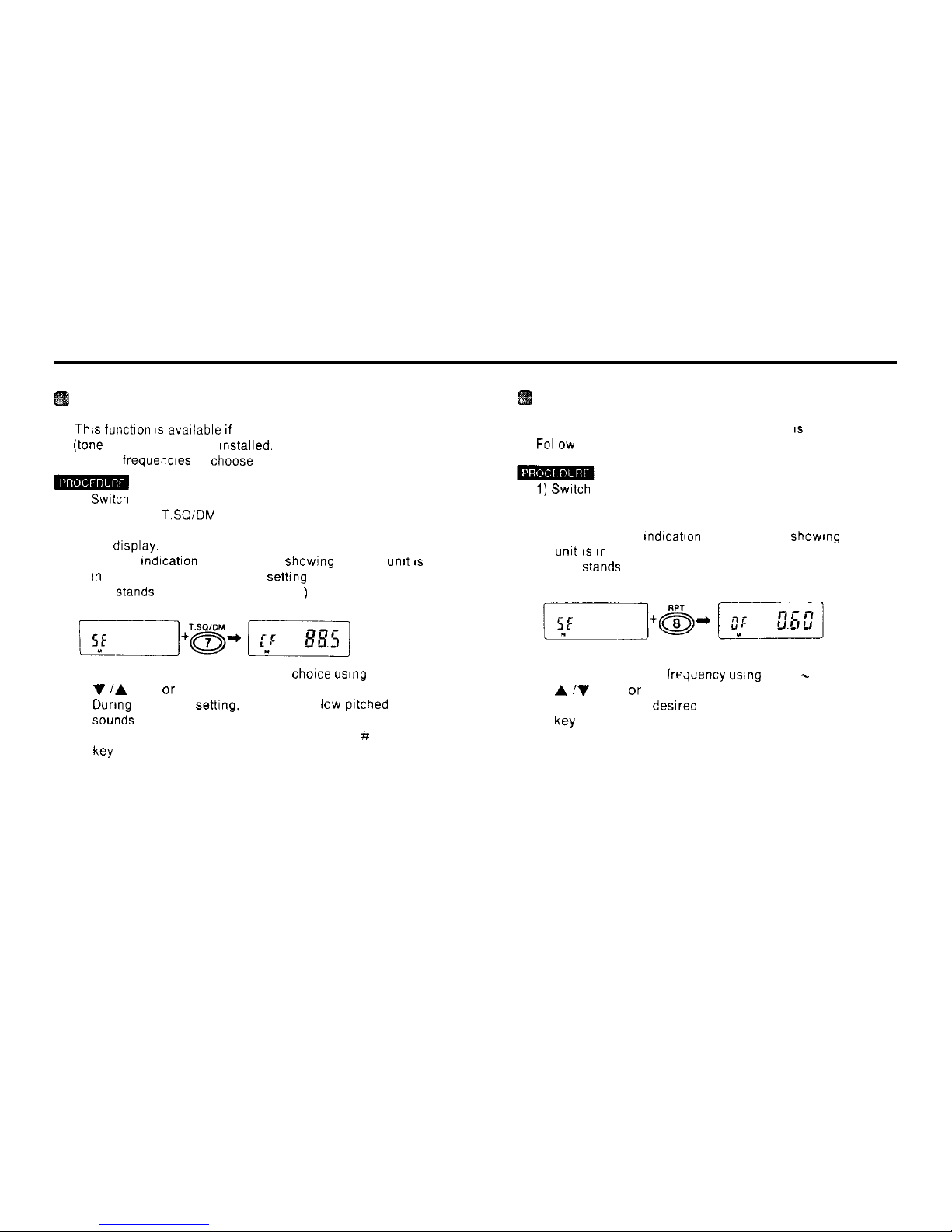
Setting the CTCSS tone frequency
n
Thrs functron IS
avarlable rf the optional CTCSS unit
(tone
squelch) has been
rnstalled.
There are 38 tone
squelch frequencres to
choose
from.
-
1)
Swatch
to the set mode.
2) Press the 7
T.SQ/DM
key.
The current CTCSS tone frequency settrng appears on
the drsplay.
The CF
tndrcatron
also appears. showrng that the
unrt IS
tn
the CTCSS tone frequency sethng mode.
(CF
Stands
for CTCSS FREQUENCY
)
3) Select the tone frequency of your
chorce usrng
the
V /A
keys or the rotary channel selector
During
frequency setttng. a puff (short low
prtched
beep)
Sounds
at 88.5 Hz.
4) After settrng the desired frequency. press the # CL PS
W
Changing the offset frequency
n The factory settrng for the offset frequency
IS
600 KHz.
Follow the procedure below to set a new offset frequency
1) Swatch
to the set mode
2) Press the 8 RPT key
The current offset frequency settrng appears on the dis-
play The [OF]
tndrcatron
also appears.
showrng
that the
unrt IS In
the offset frequency settrng mode
(OF Stands for OFFSET FREQUENCY )
3) Set the new offset freduency
usrng
the 0 - 9 keys, the
A iV
keys. or the rotary channel selector
4) After setting the desrred frequency. press the # CL PS
key
19
Page 21
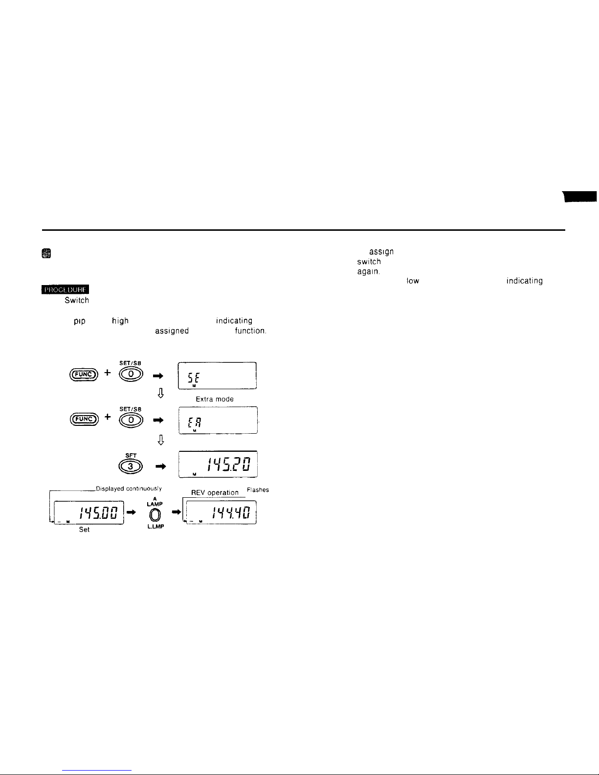
Assigning the LAMP key to the REV
function
3) To
assrgn
the LAMP key back to the LAMP function.
1)
Switch
to the extra mode.
2) Press the 3 SFT key.
swrtch
back to the extra mode and press the 3 SFT key
agarn.
A puff (short low pitched beep) sounds.
rndrcatrng
that
the LAMP key has been assigned back to the LAMP
function
A
prp
(short high pitched beep) sounds.
tndrcatrng
that
the LAMP key has been
assrgned
to the REV funchon.
Set mode
20
Page 22
Paging Operation
n This function
tan
be used to page individual stattons (per-
n
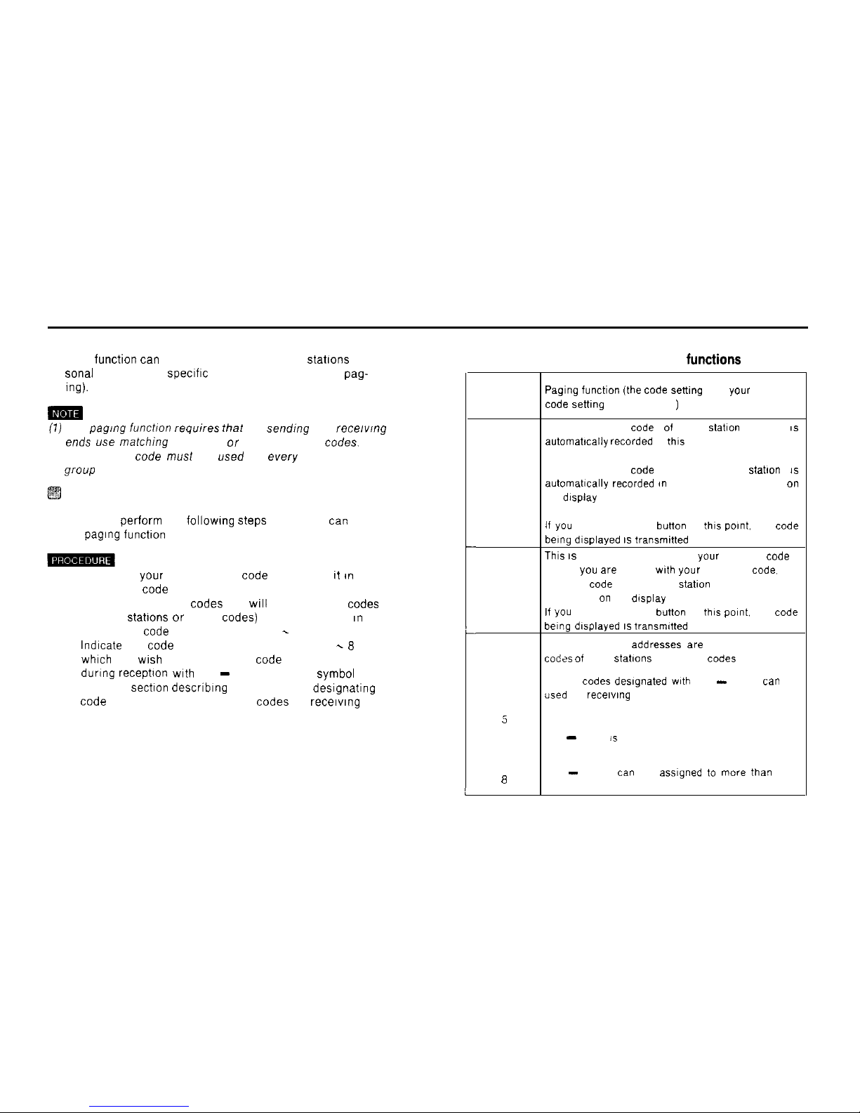
Code address numbers and their
functions
sonal pagtng) or a spectftc group of stations (group pag-
ins).
(1)
The
Pagfng
funcbon requires that the sending and recew!ng
ends use matthing
personal or group paging
Codes.
The
same group code must be used by every member of the
group
Preparations for paging
n You must perform the followtng
Steps
before you
tan
use
the
pagtng
functton
1) Decide on your own personal code and record tt
tn
memory at code address number 0
2) Decide on the other
Codes
you
WIII
use (personal
Codes
of other
Stattons
or group
Codes)
and record them
tn
memory at
code
address numbers 1 = 8
3)
Indtcate
the
code
address numbers between 1 -
8
whtch
you wsh to use as group code address numbers
durtng
recephon wth
the - (decode mark)
Symbol
(See the
sectton
describtng the method for destgnattng
code
address numbers as group
Codes
for recetwng )
t
i
Memory
address
Pagtng functton (the Code setbng
and
your
personal
number
code setttng
are broadcast
)
The personal
Code 01
the
Statton
called
IS
automatrcally recorded
at
this
address
The personal
Code
of the other
Statton IS
P
automatlcally recorded m
memory and appears
on
the display
if you
press the PTT
button
at
this potnt.
the
code
being dtsplayed IS transmttted
Thts IS
the memory address for your personal
code
When
you arc
called wth
your
personal
Code.
the
0
personal
Code
of the other
statlon
(memory address
0) appears on the display
If you
press the PTT
button
at
this polnt.
the
Code
being dtsplayed IS transmttted
1
These memory
addresses arc
for the personal
2
Codes of
other
Stattons
and group
Codes
3
Group
Codes deslgnated
wth the - mark
tan
be
4
used
for
recetwng
5
6
The
-
mark 1s the decode mark
7
8
The- mark tan be
asslgned to more than
one
memory address
,
L
21
Page 23
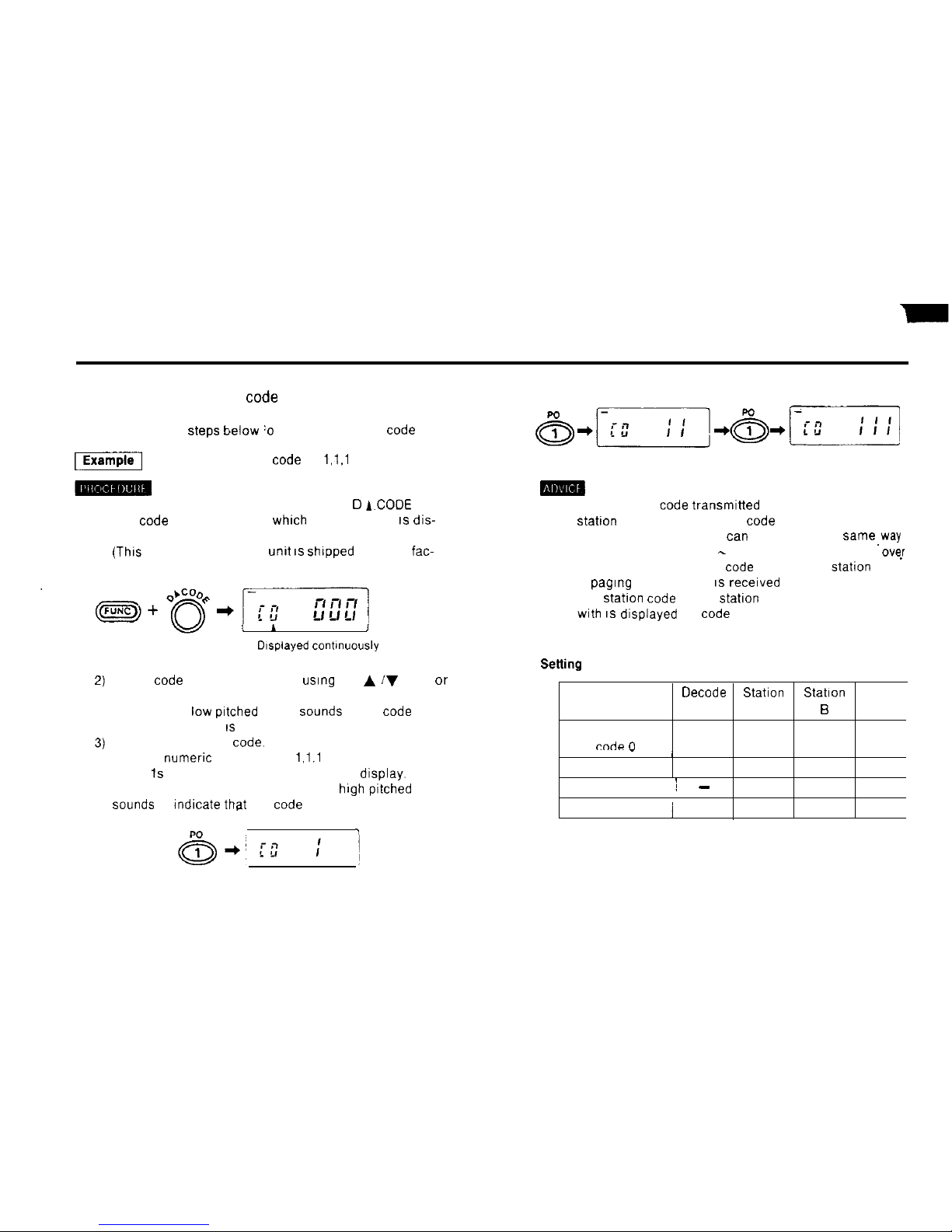
1) Setting your-personal
code
n Codes consist of three numerals.
Perform the
Steps
below :o set your personal code
-1
Setting the personal code to
1,l.l
1) Hold down the FUNC key and press the Cl
A.CODE
key
The
code
address number
whrch
was used last IS dis-
played.
(Thrs
is set to 0 when the
unrt IS shrpped
from the
fac-
tory.)
1) The personal code transmrtted to you from the other
Statton
is stored at memory code address number P
Code address number P
tan
be used in the same,way
as address numbers 1
Selting
example
-
8, but it is automatically
0vs.r
written with the personal
code
of the other
Station
when
a
pagrng
transmission IS recerved
2) The stahon code of the
statron
you are communicating
with IS displayed as code address number P
Select code address number 0
usrng
the A iV keys or
v
the rotary channel selector.
i I
A puff (short
low prtched
beep)
Sounds
when code
J
address number 0 IS selected
Drsplayed contrnuously
Input your personal
Code.
Use the numeric keys to Input
1,l.l
Three 1s appear one after another on the display. When
the last digit is entered, a peep (long
high
pitched beep)
Sounds
to
rndrcate
that the code has been set.
rm-9
‘I
Memory address
Oecode
Station
Station
Statton
number mark
A
B
C
Your personal
rndn l-l
111
222
333
____
_
/
Code 1
222
111
111
Code 2 /
-
050 050 050
Code 3
j
333 333 222
22
Page 24
2) Setting personal
Codes
of other stations
1) Hold down the FUNC key and press the D A CODE key
2) Select the
code
address number of your
chorce ustng
the A /V keys or the rotary channel selector
3) Input the personal code
usrng
the numeric keys.
To record more than one code m memory, repeat
Steps
2) and 3) above as many times as necessary.
(1) Input the group
Codes
you
wrsh
to use for receivrng as weil
as those you will use for transmrtting.
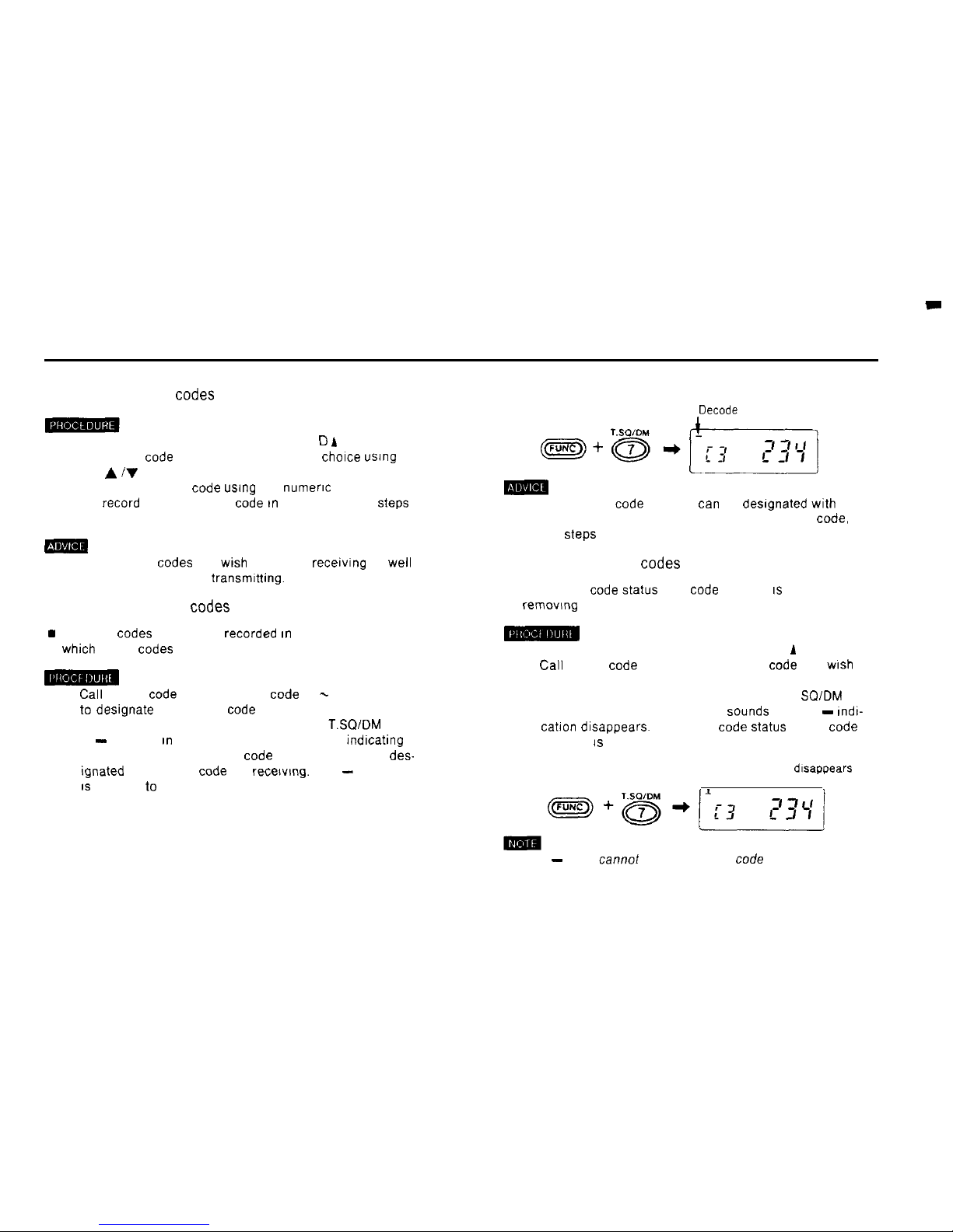
3) Designating group
Codes
for receiving
w
After the
Codes
have been recorded rn memory, designate
whtch
group
Codes
you wish to use for receiving.
1)
Cal1
up the code address of the
code
(1 - 8) you wish
to
desrgnate as a group code for receiving
2) Hold down the FUNC key and press the 7
T.SQ/DM
key.
A - appears rn the upper left of the display
indrcatrng
that the currently displayed code address has been
destgnated as a group code for recetvmg. The - mdication
IS
referred to as the decode mark.
Decode
mark
LI
m
(1) More than one code address
tan
be desrgnated with the
decode mark. To desrgnate more than one group
Code,
repeat
Steps
1) and 2) above as many times as necessary.
4) Canceling group
Codes
n The group code
Status
of a
code
address IS canceled by
removrng the decode mark.
1) Hold down the FUNC key and press the D A CODE key
2)
Cal1
up the code address of the group code you
wrsh
to
cancel.
3) Hold down the FUNC key and press the 7 T
SQ/DM
key
A puff (short low pitched beep)
Sounds
and the -
rndr-
catron
drsappears. The group code
Status
of the code
address IS canceled
The decode mark
drsappears
(1) The - mark cannot be canceled for code address number 0
23
Page 25
Paging Operation
n
Pagrng
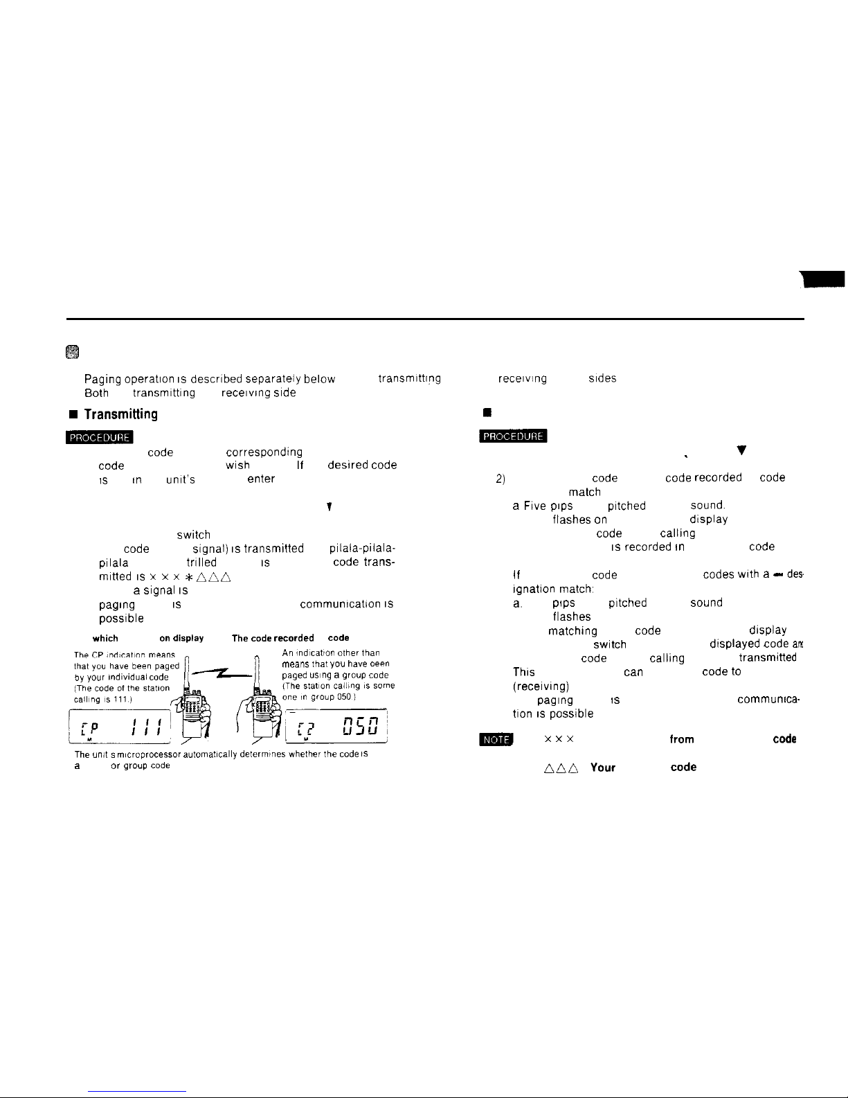
operahon 1s descrrbed separately below for the transmrttrng (you) and recerving (other)
srdes
n 60th the transmrttrng and
recervrng srde
must use the same frequency
w Transmitting
side (you)
w Receiving (other) side
1) Select the code address correspondrng to the personal
1) Hold down the FUNC key and-press the C V PAG key
code
of the statron you
wrsh
to page If the desrred code
IS
not rn the umt’s memory. enter it
2) Press the # CL PS key
2)
PAG P appears on the drsplay
’
If the recerved code and the
code
recorded at code
address 0
match
3) Hold down the FUNC key and press the C T PAG key
a Frve prps
(high
prtched
beeps)
Sound.
PAG P appears on the drsplay
b PAG flashes on and off on the dtsplay
4) Press the PTT
swrtch
c The personal code of the calhng statron appears on
The code (DTMF
Signal) IS
transmrtted and pilala-prlala-
prlala
(repeated trrlled beeps) IS heard The code trans-
mrtted IS x x x *niin
5) When a
Signal IS
recerved from the other statron, the
pagrng
mode IS canceled and normal communrcation
IS
possrble
3)
the drsplay and IS recorded rn memory at code
address P.
Code
which
appears on
displsy
The code recorded
at
Code
address 0
n
All indlca,lo” other tkr
CP
4)
If the recerved
code
and one of the
Codes wrth a - des
rgnahon match,
a.
Five
prps
(high
prtched
beeps)
Sound
b PAG flashes on and off on the drsplay.
c The
matthing
group code appears on the display
When the PTT
swtch
is pressed, the drsplayed
Code arx
the personal code (of the callrng side) are
transmrtted
Thrs
means that you
tan
send your code to the other
(recerving) statron.
The
pagrng
mode IS canceled and normal
commumca-
tron IS possrble
by
your ,ndlwdual
code
means mat
you
have
oeen
paged
ustng a group
Code
The un,, s m,croprocessor automat~cally defermines whefher ,he
code
IS
a
private or
group code
5)
x x x
: Code selected
from
the available
code
addresses
nnf~
:
Your
personal
code
24
Page 26

j
Operation example i Asstgn
Codes
to code address numbers.
m
m Durmg pagtng
Operation. the code shown on the drsplay
IS transmrtted.
Statton A. Code address assrgnments
0
111 - personal code for
Statton
A
1
: 222 - personal code for Station B
2
050 - group
code
(Add the decode mark to
each
address number.)
(PTT Lwtton depr.?s*edl
n
Stahon 6. Code address asstgnments
0
222 - personal code for
Statton
B
1
111 - personal code for
Statton
A
2
: 050 - group code
(Add the decode mark to
each
address number )
s,a,,an s F’a*hes
i
Reception error
25
Page 27

(1) If !he
Codes
match, the unit drsplays the contents of
code
(1) If the C 7 PAG key is pressed
wrth
the FUNC key held
address P, rndicating that you have been paged using your down
whrle
the PAG rndication IS flashmg, PAG
drsappean
personal code If somethrng other than code address P and the rndication 1 remains
appears. you have been paged
usrng
a group code
Thts
means that the PAG functton is temporarily
sus-
(2) The personal code of the calling
statron IS
recorded at code pended
3)
m
address P even rf you are paged using a group
Code.
By checktng code address P you
tan
determtne
whrch
member of the group is callrng.
Communicating after
Codes
match
If the
Codes
match,
switch
the PAG functton off and commu-
ntcate
normally.
(2) Normal communrcation IS
possrble
when the 1
mdrcatton
IS
drsplayed.
]ust
as rf step 1) at left had been performed
However, rn
thrs Status
the mtcfoprocessor still considers
the paging function to be on. So if you turn the power off
and then on, or
Change
the frequency, PAG will reappear
on the display
1) Hold down the FUNC key and press the C 7 PAG key
twice.
The display indtcation changes from PAG B to CSQ to
nothing.
Thrs
indicates that the PAG function IS off.
Continue with normal communication.
26
Page 28

Code Sauelch Operation
n As
wrth
the
pagrng
functfon, code squelch permtts commu-
ntcatlon
only after
matthing
a 3-dlgit
Code.
It operates simi-
larly
to the tone squelch function.
1) Hold down the FUNC key and press the Cl A CODE key.
2) Select the
code
you
wrsh
to
use
3) Press the # CL PS key
4) Hold down the FUNC key and press the C 7 PAG key
twice The CSQ indication appears on the display
(1) Commumcation is not possible !f the code selected does not
match
that of the other Station. Decide on the code to be
used beforehand.
(2) Any code address number
tan
be used for this function
Code squelch
1
I
5) Begin
code
squelch operatron
“sing
the code you have
selected.
27
Page 29
Tone
Scwelch
Operation
n The tone squelch function requires that the optional
CTCSS unit be installed.
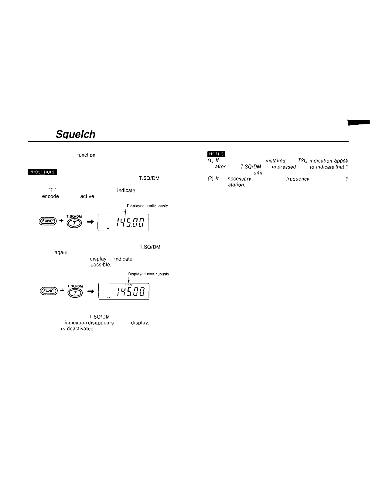
(7)
ff fhe CTCSS is nof insfalled. fhe
TSO
indicatron
appear
1) Hold down the FUNC key and press the 7
T.SQ/DM
key
affer fhe 7
T.SQIDM
key is pressed once to indfcafe fhat
Ib
required CTCSS
mit
has nof been connecfed.
f21
ff is necessarv fhaf fhe fone freouencv rnafch fhaf of
fh
once.
A
“T”
appears on the display to rndicate that the tone
encode mode is
actrve.
ofher
Station.
Dlsplayed contlnuously
2) Hold down the FUNC key and press the 7
T.SQ/DM
key
once
agarn
TSQ appears on the display to rndicate that tone
squelch Operation is
possrble.
3) To cancel the tone squelch mode. hold down the FUNC
key and press the 7 T
SQ/DM
key
The TSQ
indrcahon
drsappears on the drsplay. and tone
squelch IS deactrvated
28
Page 30

Memory Operation
W
Memory function
Storinq
frequencies in memory
The
unit
use a memory unit to implement the memory
function.
/
Enterrnq 145.10 MHz rn memory as M26
Memory operatron is therefore
possrble
only rf the memory
unit has been installed.
Installation of the memory unit is highly recommended
(The unit will operate without it, but only in the VFO
mode.)
The unit are shipped from the factory with the 40-channel
memory
unit
already installed.
1) In the VFO mode. select the frequency 145.10 MHz so
that it appears on the display.
2) Hold down the FUNC key and press the B VIM ENT key
The M
rndicatron
appears on the display
n The memory functton allows you to store frequently used
frequencies for use when needed
n Up to 40 separate frequencres
tan
be stored in memory
n The
locatrons
where frequencies are stored are called
“memory address numbers
”
n The memory address numbers range from
MO0
through
M39.
3) Press the 2 DUAL key A 2 appears on the display
below the M
4) Press the 6 F L key A peep (long
high prtched
beep)
Sounds
to
rndrcate
that the frequency has been stored in
memory
This Status IS
referred to as the memory mode
0 To store a frequency as Mol, you would press the 0 key
followed by the 1 key.
29
Page 31

Storing tone frequencies, etc. in
memory
n In addition to transmrtting and
recervrng
frequencres. the
following settings
tan
also be stored In memory by the
unit,
l CTCSS tone frequency
(Page 28)
l Tone encode mode
(Page 28)
l Tone squelch mode
(Page
28)
l Paging mode
(Page 21)
l Code squelch mode
(Page
27)
l Pagingicode squelch transmission
code address (Pages
21,27)
l Repeater mode
(Page 17)
0 Offset frequency
Page 19)
The above settrngs
tan
be stored In the umt’s memory by
performrng the appropriate operahons
whrie in
the memory
cal1
mode. See the page numbers
prrnted In
parentheses
for detarled descrrptrons of the necessary steps
30
Page 32
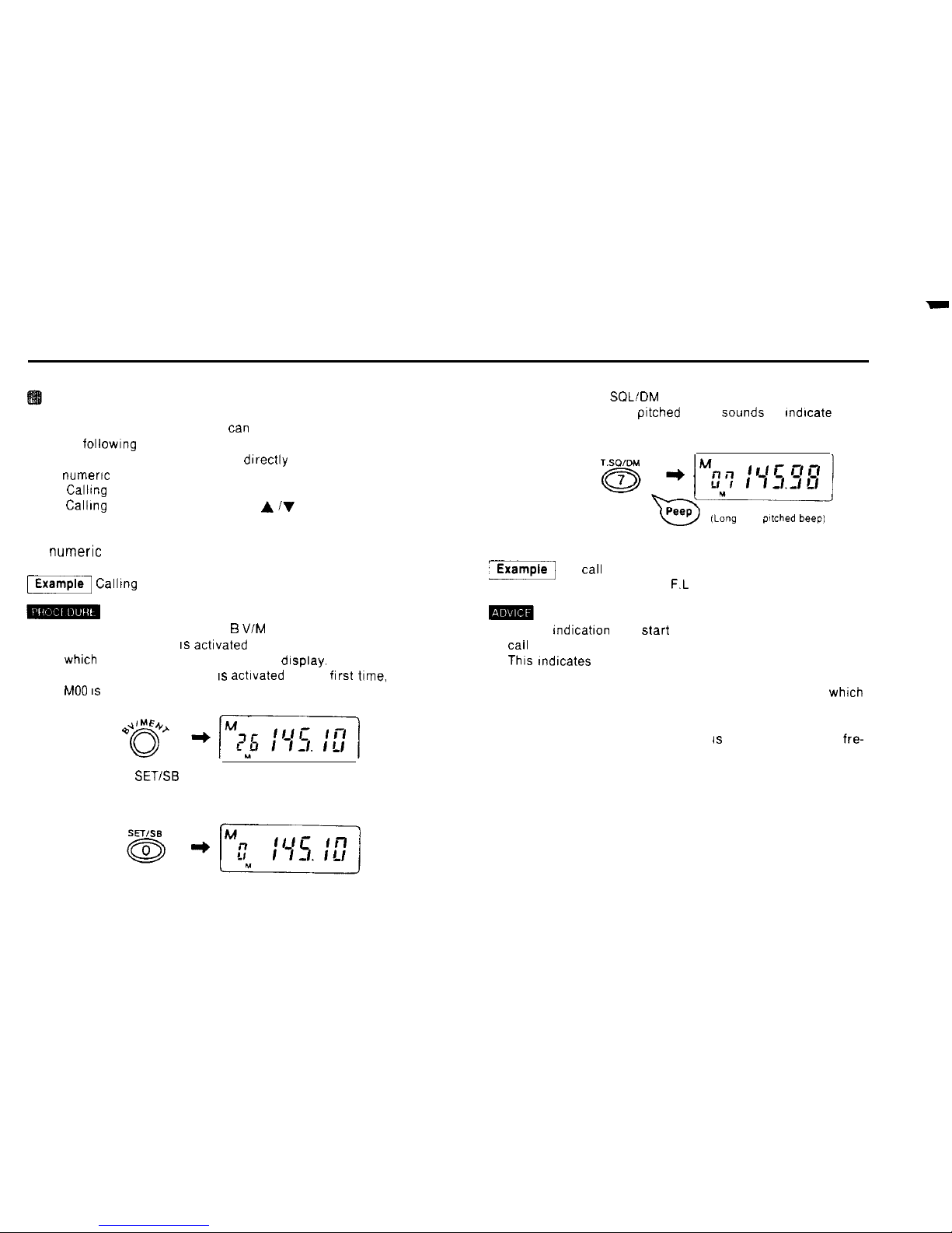
Calling up memory frequencies
n Memory (number) frequencres
tan
be called up usrng any
of the followrng three methods.
(1) Inputting the memory address drrectly usrng the
numeric keys
(2)
Callrng
up a frequency usrng the rotary channel selector
(3)
Callrng
up a frequency usrng the A iV keys
(1) Inputting the memory address directly using the
numeric
keys
m
Calltng up MO7
1) In the VFO mode. press the B VIM ENT key.
The memory mode IS actrvated and the memory address
which
was used last appears on the display.
(When the memory mode IS actrvated for the
frrst
time,
MO0 IS
displayed )
2) Press the 0
SET/SB
key
MO is displayed.
3) Press the 7 T
SQL/DM
key.
A peep (long high pitched beep)
Sounds
to
rndrcate
that
memory address number 7 has been called up
(Lang
high
ptfched
beep)
‘-1
To
call
up M26, you would press the 2 DUAL key
followed by the 6
F.L
key
(1) The M rndication may
Start
to flash on and off when you
cal1
up a memory address number.
This
Indicates that no frequency is currently assigned to
the memory address number you have selected
(in the following pages. memory address numbers to
whrch
no frequencres have been assigned are referred to as
“free memory address numbers.“)
(2) If a free memory address number IS called up, the VFO fre-
quency is displayed.
31
Page 33
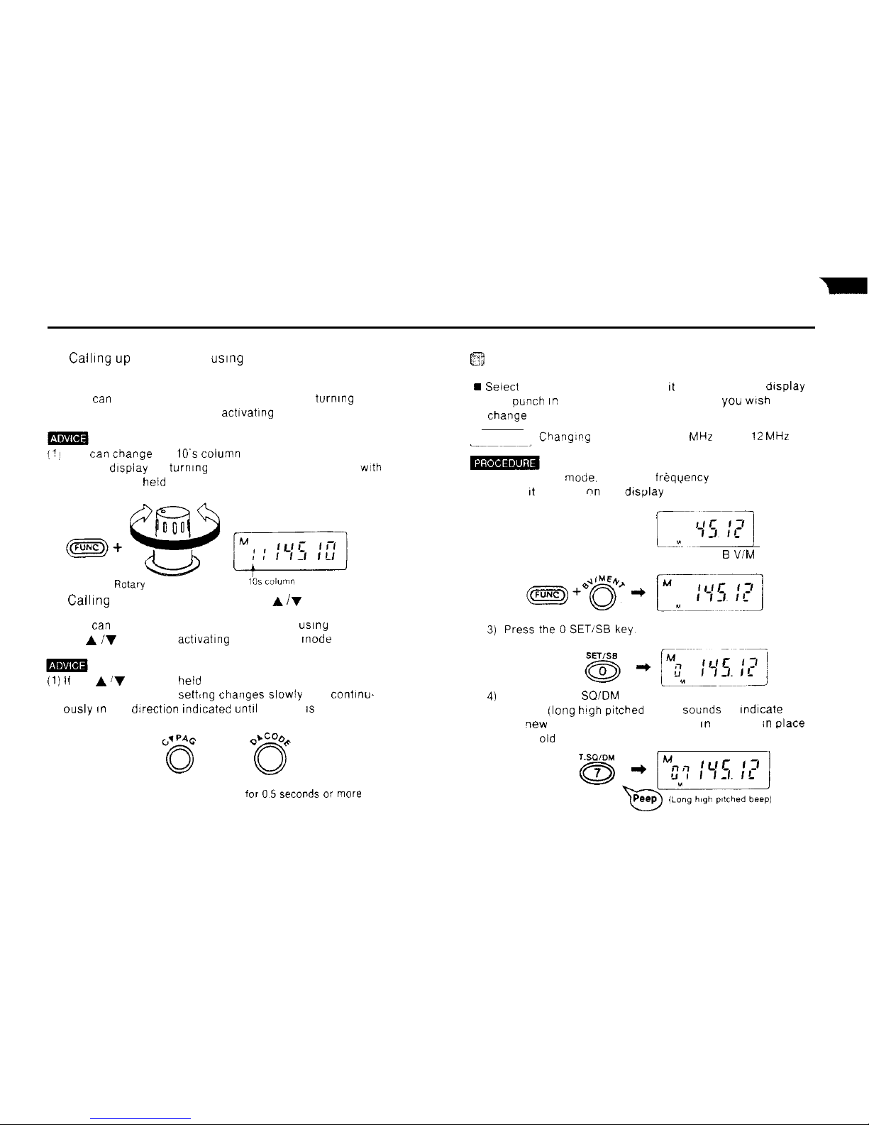
(2)
Calling up
a frequency uslng the rotary channel
selector
n You
tan
select a memory address number by turning the
rotary channel selector after activating the memory mode
f’j
You
tan Change
the
10’s column
of the memory address
number display by turning the rotary channel selector
w!th
the FUNC key
held
down
w
-
Rotary
channel selector
1bs ‘OIUrn”
(3)
Calling
up a frequency using the
A/V
keys
n You
tan
select a memory address number usiny
the A /y keys after actlvatlng the memory tnode
(1) If
the A ‘v keys are
held
down for 0 5 seconds or more.
the memory address
sett$ng
changes slowly and continu-
ously an the direction Indlcated
until
the key is released
Hold down
for OSseconds or more
El
Changing a memory frequency
9 Seiect
the new frequency so that It appears on the display
and
Punch Er!
the memory address number you
wish
to
Change
Example
Chang;pg MO7 from 145 50
MHz
to 145 12
MHz
__~~~~_
1) In the VFO
mode.
select the freqyency 145 12 MHz so
that It appears nn the display
[^-yi
~q
2) Hold down the FUNC key and press the B
V/M
ENT key
4)
Press the 7 T
SOIDM
key
A peep ilong
blgh pitched
beep)
Sounds
to Indlcate that
the
qew
frequency has been stored an memory in
place
of the
old
one
32
Page 34
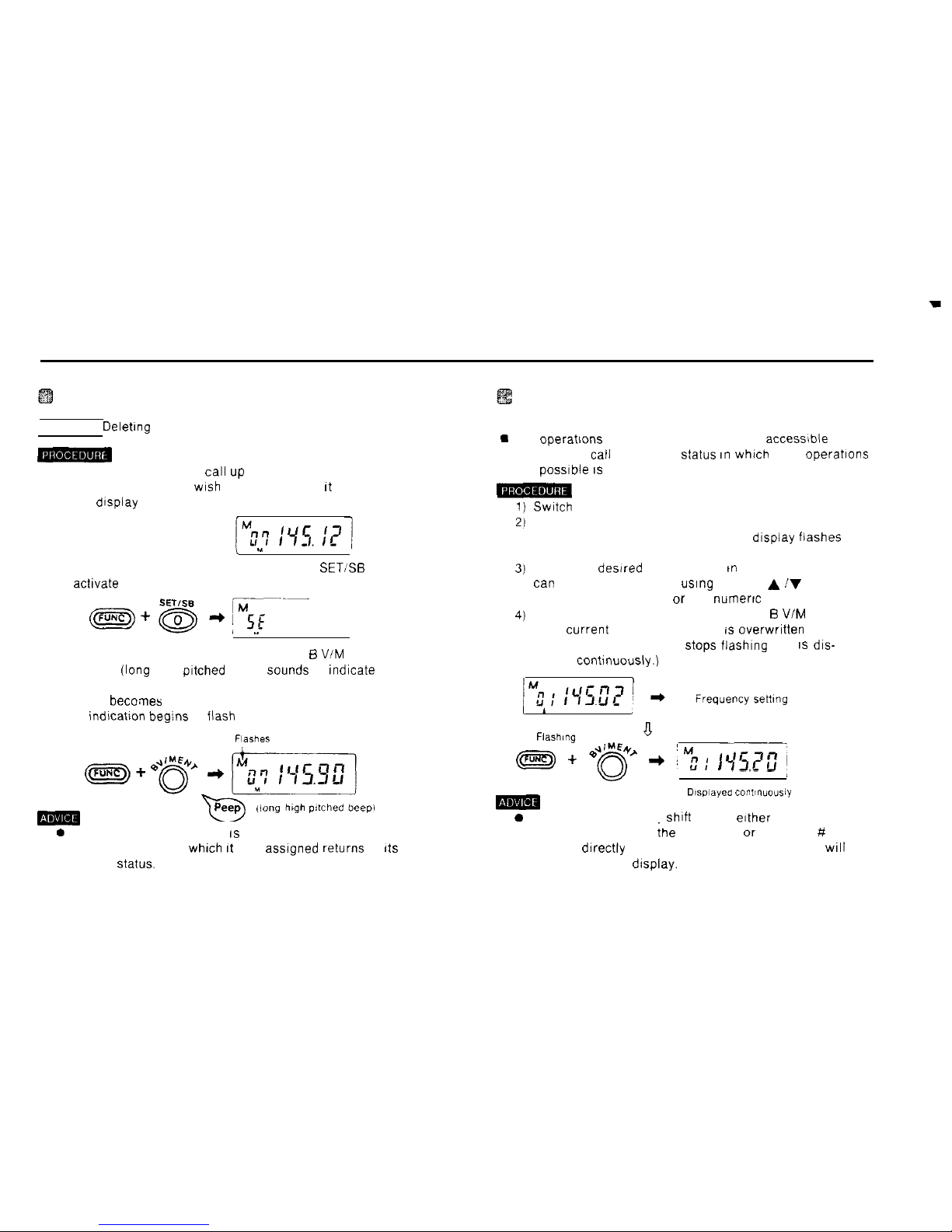
Deleting a memory frequency
Example Delehng the frequency 145.12 MHz from MO7
1) In the memory mode,
cal1 up
the memory address
whose contents you
wrsh
to delete so that ft appears on
the dtsplay
, u
J
2) Hold down the FUNC key and press the 0
SET:%
key to
actrvate the set mode
3) Hold down the FUNC key and press the 5 VIM ENT key
A peep
(lang
high pftched beep)
Sounds
to fndicate that
the memory frequency has been deleted
(MO7 becomes a free memory address number and the
M mdlcation beg:ns to
flash
on and off.)
FlaSheS
-Tl
Peep
,iong h@l pltched tEepi
0 After a memory frequency IS deleted. the memory
address number to
whrch ft
was
assrgned
returns to
rts
factory
Status.
Changing frequencies in the memory
mode (memory shift mode)
m
The operatrons of the VFO mode are also accessible from
the memory
cal1
mode The
Status In whxh
such operations
are possfble IS referred to as the memory shift mode
m
Swatch
to the memory mode
Hold down the FUNC key and press the 3 SFT key
The memory address number on the dfsplay flashes on
and off
Select the desired frequency As m the VFO mode, you
tan
select the frequency using the and A iV keys. the
rotary channel selector or the
numerrc
keys
Hold down the FUNC key and press the B VIM ENT key
(The current memory frequency rs overwrrtten and the
memory address number
Stops
fiashrng and IS dis-
played contrnuously.)
Fiash,“g
a
pF&
+
e4&
+
#y.; I,r7<,
f r3.Cu
m
Dlsplayed
contl”“o”siy
0 To cancel the memory shift mode, erther hold down the
FUNC key and press the 3 SFT key or press the # CL
PS key drrectly The previous memory frequency will
reappear on the drsplay.
33
Page 35
Scan ODeration
Scan
types
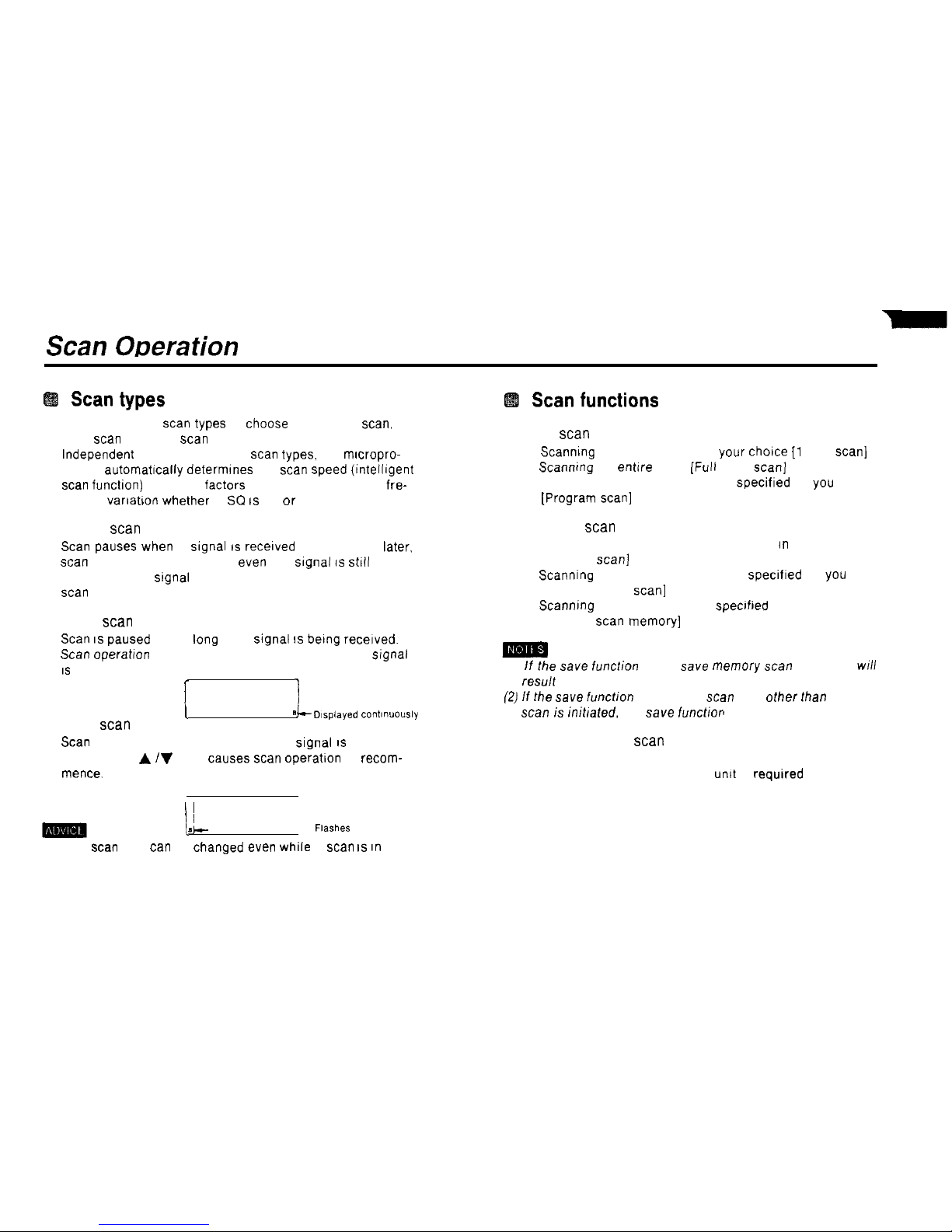
n There are three
scan
types to
choose
from pause
scan,
busy
scan
and hold
scan
Independent of the above three
scan
types, the mrcropro-
cessor automattcally determrnes the
scan Speed
(tntelligent
scan
functton) based on factors such as the amount of fre-
quency variabon whether T SC IS on or off. etc
(1) Pause
scan
Scan
pauses when a
Signal IS
recerved Five seconds later.
scan
Operation recommences even if a srgnal IS still berng
received (If the
Signal
is lost in less than five seconds,
scan
recommences immediately )
(2) Busy
scan
Scan IS
paused for as lang as a
Signal IS berng
recetved.
Scan
operatlon recommences two seconds after the Signal
IS
lost.
l
1
I
8
(3) Hold
scan
k-D~spiayed
cont~nuously
Scan
is temporarily suspended when a
Signal IS
received.
Pressing the A IV kevs
Causes scan
operabon to recom-
mence.
Scan functions
(1) VFO
scan
1) Scanntng the 1 MHz range of your
chotce [l
MHz scan]
2) Scanmng an
entere
band
(Full
band scan]
3) Scanning a range of frequencres specifted by you
[Program scan]
(2) Memory
scan
1) Scanning all memory addresses stored an memory
[Memory scan]
2) Scanntng a memory address block specified by you
[Block memory
scan]
3) Scannmg memory addresses
specrfred
by you
[Memory
scan
memory]
(1) If fhe
save
function is on,
save
memory
scan
Operation
wfll
result
(2) If fhe save
function is on and a
scan
type other fhan memory
scan is
initlated, the
save
function is suspended.
(3) Tone frequency
scan
1) Scans the tone frequencres
The optional CTCSS untt is requtred
1
sr
Flashes
(1) The
scan
type
tan
be changed even while a
scan IS in
progress. (See page 38 for details.)
34
Page 36
Using the
scan
functions
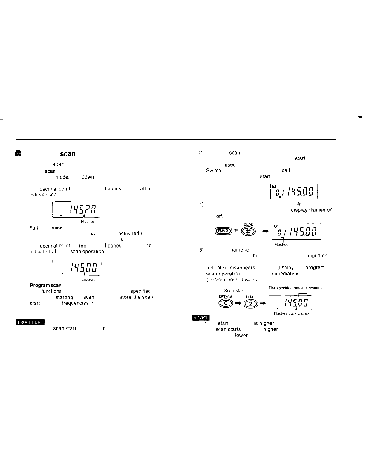
(1) Using VFO scan
(1) 1 MHz
scan
In the VFO
mode.
hold ddwn the FUNC key and press
the # CLPS key.
The dectmal polnt on the display flashes on and
Off to
Indlcate
scan
Operation
3)
(
u
(2)
Full
band
scan
C-J
Flashes
1) Press the CALL key. (The
cal1
mode is activated.)
2) Hold down the FUNC key and press the # CL PS key
The decimal Point on the display flashes on and off to
Indicate full band
scan
operatlon.
5)
--“-T!zb
(3)
Program scan
This functions scans a range of frequencies specified by
you Before startlng the
scan,
you must store the
scan
Start
and end frequencles in memory
Store the
scan
end frequency in memory. (Any memory
address number other than that of the
Start
frequency
may be
used.)
Swatch
to the memory mode and
cal1
up the memory
address number of the
Start
frequency.
(
Y
i
Hold down the FUNC key and press the # CL PS key
The memory address number on the dlsplay flashes
on
and
off.
Press the
numerx
keys corresponding to the memory
address number of the end frequency. After Inputting
the number (two digits). the memory address number
Indlcation dtsappears from the display and program
scan
operatton commences Immediately
(Declmal polnt flashes )
The speclfled range is scanned
-
1) Store the
scan Start
frequency In memory (Any memory
address number may be used )
. If the
Start
frequency IS higher than the end frequency.
the
scan Starts
from the higher frequency and proceeds
towards the lower
35
Page 37
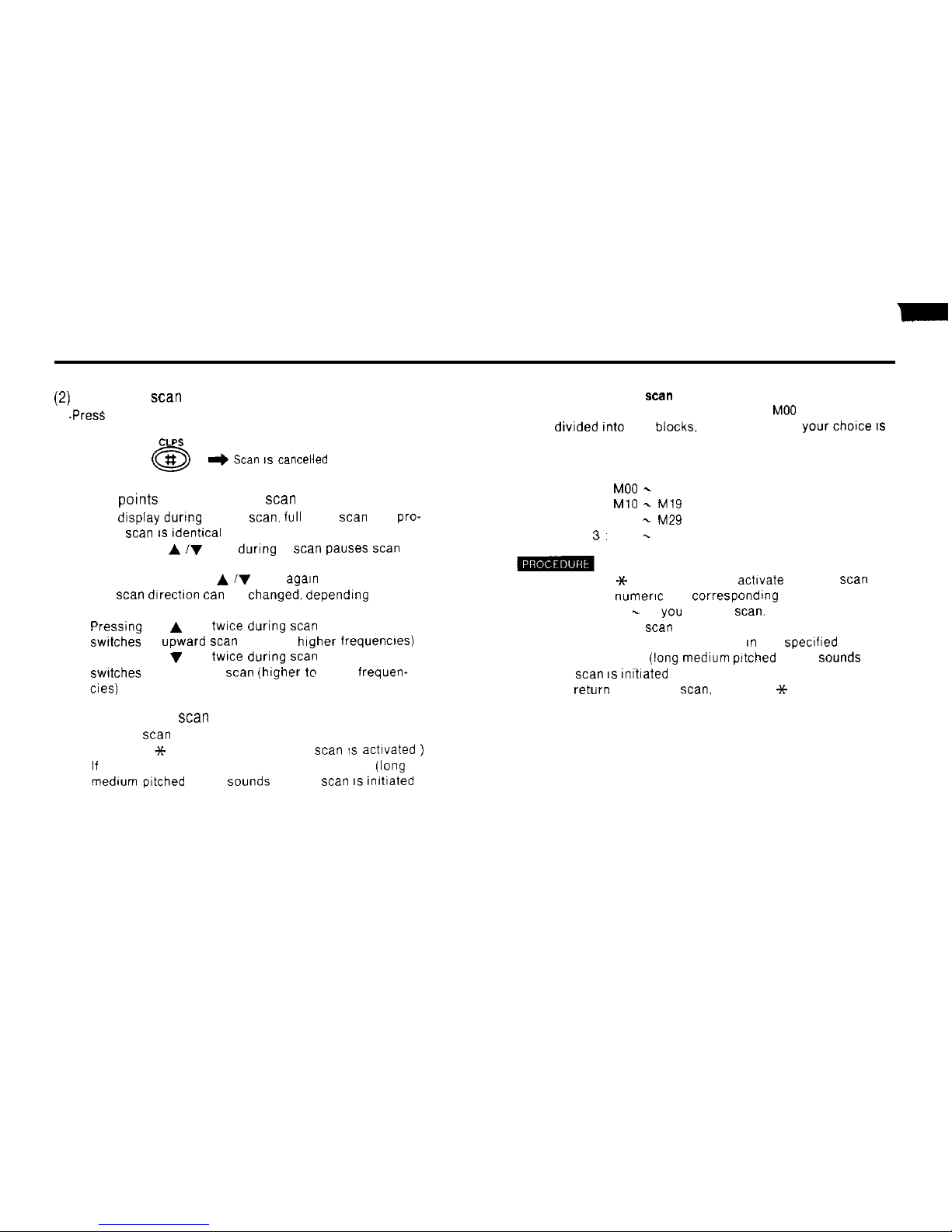
(21
Cancelling
scan
Operation
.Press
the # CL PS key.
CLPS
+ Scan IS cancelled
(3) Other Points regarding VFO
scan
1) The drsplay durtng 1 MHz
scan. full
band
scan
and
pro-
gram
scan IS rdentrcal
2) Pressing the A iV keys during a
scan
pauses
scan
Operation
To restart, press the A iV keys
again
3) The
scan
drrection
tan
be changed, dependrng on the
key used to restart it
Pressung
the A key
twrce
during
scan
Operation
swtches
to upward
scan
(lower to higher frequencres)
Pressing the V key
twrce
during
scan
Operation
swrtches
to downward
scan
(hrgher to lower frequen-
cies)
(4) Using memory
scan
(1) Memory
scan
Press the ++ MS MS.M key (Memory
scan 1s
actrvated
)
If
all memory address numbers are free. a boo
(lang
medium pitched beep)
Sounds
and no
scan IS
imtiated
(2) Block memory
scan
The memory address numbers from
MO0
to M39 are
divrded
tnto
four
blocks.
and the block of your
chorce IS
scanned.
The memory address number block assignments are as
follows
Block 0
MO0 -
MO9 are scanned
Block 1
MlO -
M19
are scanned.
Block 2 M20 -M29
are scanned
Block 3. M30
-
M39 are scanned.
1) Press the 3t MS MS M key to actrvate memory
scan
2) Press the
numerrc
key correspondfng to the number of
the block (0
-
3) you wish to
scan.
Block memory
scan
begins.
If all memory address numbers rn the specrfied block
are free, a boo
(lang
medium pttched beep)
Sounds
and
no
scan IS rnmated
3) To return to memory
scan,
press the * MS MS M key
36
Page 38
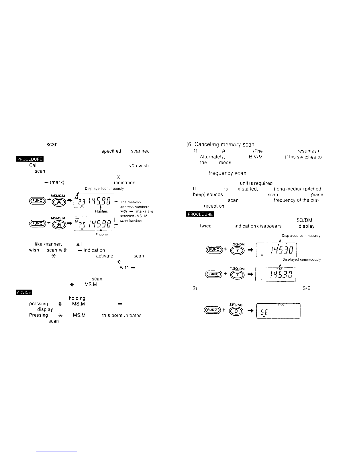
(5) Memory
scan
memory
n Only the memory address numbers spectfled are scanned
1)
Cal1
up one of the memory address numbers
YO., wsh
to
scan
2) Hold down the FUNC key and press the Sc MS MS hl
key A -(mark) appears above the M indication
Dtsplayed co”l~nuo”sly
3) In like manner, mark
all
the memory addresses you
wish
to
scan
with the - Indicabon
4) Press the X- MS MS M key to activate memory scav
5) Hold down the FUNC key and press the 3~ MS MS M
key Only the memory address numbers
wtth -
marks
are scanned.
6) To return to normal memory
scan.
hold down the FUNC
key and press the Y MS
MSM
key.
m
l In the VFO mode. holding dawn the FUNC key and
presslng the ++ MS
MSM
key Causes a - to appear on
the display
Pressung
the ++ MS
MS.M
key at
thls Point
Imtiates
memory
scan
memory
161 Canceling memcry scan
1)
Press the ;f CL PS key
lThe
memory mode resumes
I
Alternate’y.
press tne B VIM ENT key
!This
switches
to
:be VFO
mooe
,
(7) Tone
!requency scan
n The optional CTCSS
timt IS
required.
If
the CTCSS is not Installed. a boo [lang medium
pctcned
beepi
Sounds
and tone frequency
scan
does not take
piace
Tone frequency
scan
scans the tone frequei;cy of
rhe
cur-
rent receptlon frequency
1) Hold down the FUNC key and press the 7 T
SQ’DM
key
twice The TSQ indication dlsappears on the display
2)
Hold down the FUNC key and press the 0 SET
SiB
key
37
Page 39
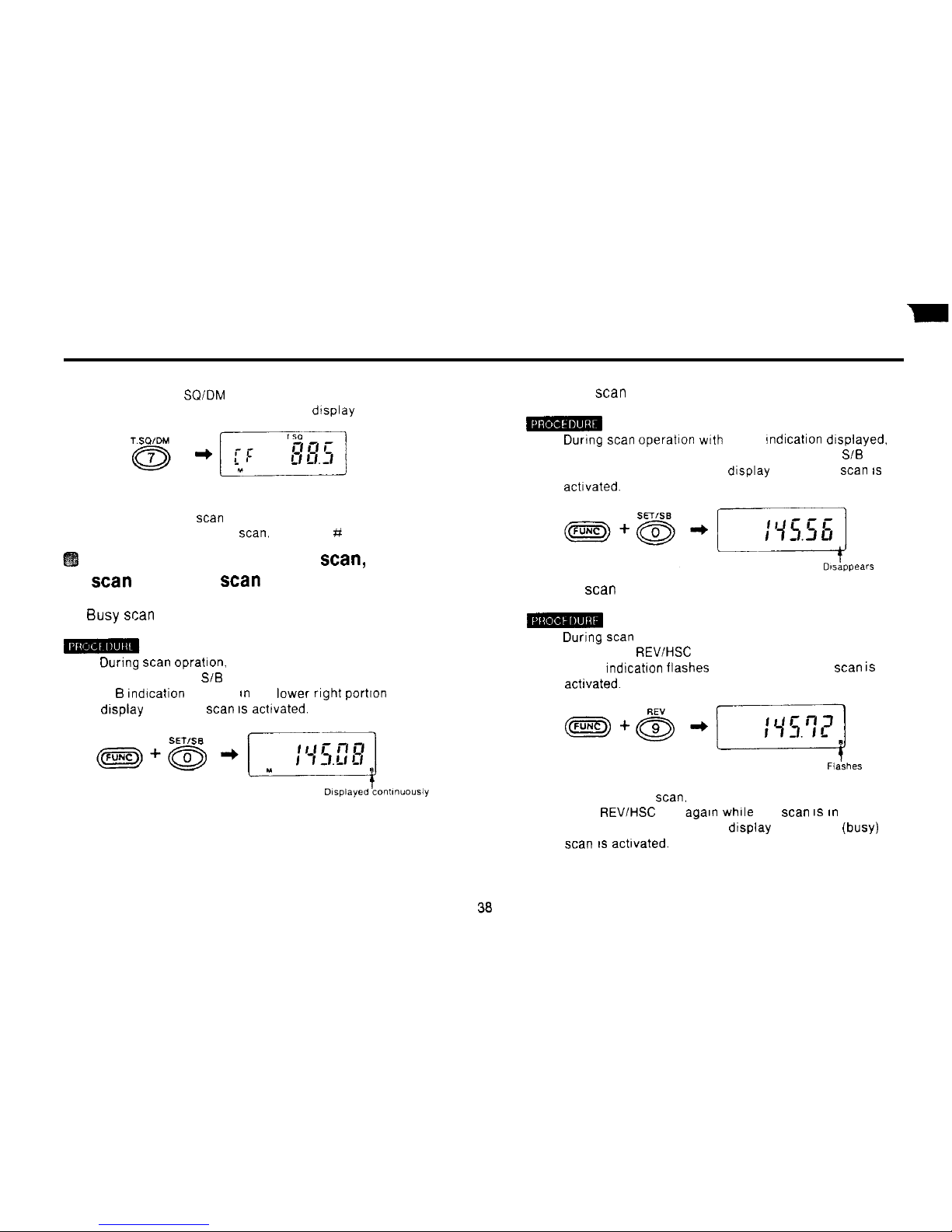
3) Press the 7 T
SQIDM
key
The tone frequency appears on the dtsplay
4) Hold down the FUNC key and press the # CL PS key
Tone frequency
scan
commences
5) To stop tone frequency
scan,
press the # CL PS key.
Switching between pause
scan,
busy
scan
and hold
scan
(1) Busy scan
1) During
scan
opratton. hold down the FUNC key and
press the 0 SET SiB key
A B Indtcation appears an the lower right portton of the
display and busy
scan IS
achvated.
(2) Pause scan
1) During
scan Operation wtth
the B indtcatton dtsplayed.
hold down the FUNC key and press the 0 SET SiB key
The B dtsappears from the display and pause
scan IS
acttvated.
(3) Hold scan
1) Durtng
scan
Operation, hold down the FUNC key and
press the 9
REVIHSC
key.
The B indication flashes on and off and hold
scan is
achvated.
2) To cancel hold
scan.
hold down the FUNC key and press
the 9
REV/HSC
key agaln while the
scan IS tn
progress.
The B dtsappears from the dtsplay and pause (busy)
scan IS
acttvated.
Page 40
(1) Busy
scan
and pause
scan tan
be set independently
ot
VFO
scan
and mernory
scan.
(2) Hold
scan tan
be used together
wdh
VFO
scan
or
mem-
ory
scan.
(3) During hold
scan,
switching between pause and busy
scan
is posstble, but pause (busy)
scan WIII
not
com-
mence
until hold
scan IS
turned off.
(4) Hold
scan
Operation IS not possible during tone fre-
quency
scan.
(5) The
Order
of precedence of the different
scan
types is
as follows: hold
scan >
(busy
scan
= pause
scan)
39
Page 41
CALL Operation
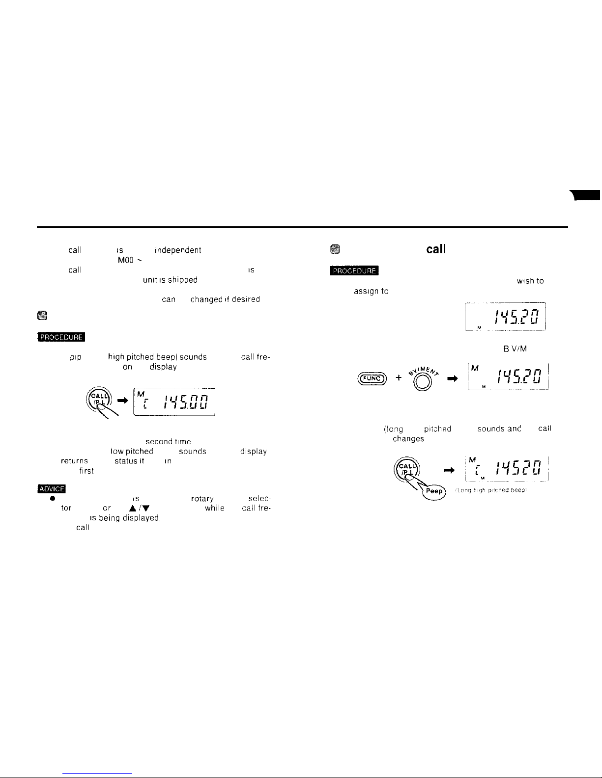
n The
cal1
memory 1s entirely rndependent of memory
address numbers
MO0 -
M39
n The
cal1
frequency (referred to as the main channel) IS set
to 145.00 MHz when the
umt IS
shipped from the factory
n The CALL memory frequency
tan
be changed rf desrred
Using the CALL key
1) Press the CALL key
A
prp
(short
high
pitched
beep] Sounds
and the
cal1
fre-
quency appears on the dispiay
2) Press the CALL key a
second time
A puff (short
low prtched
beep)
Sounds
and the display
returns to the
Status It
was In before the CALL button
was
frrst
pressed
0 If the # CL PS key is pressed, the rotary channel selec-
tor turned, or the A iV keys pressed
whrle
the
cail
fre-
quency IS
berng
drsplayed, the VFO frequency replaces
the
call
frequency
Changing the
cal1
frequency
1) In the VFO mode, select the frequency you
wrsh to
assrgn to
the CALL key
2) Hold down the FUNC key and press the B VIM ENT key
3) Press the CALL key
A peep
(lang
high
prtched
beep)
Sounds ani
the
cal1
frequency changes to the new frequency
40
Page 42

Dual Wa tch ODera tion
H
Receiving Signals on two frequencies
alternately
This
functlon IS called dual watch It allows you to momtor one
of the memory frequencles
(MO0 -
M39) or the
cal1
frequency
and the VFO frequency alternately
During
dual watch operabon, the memory frequency
IS
recelved (and appears on the dlsplay) once every three
sec-
onds.
This Status IS
referred to as dual watch mode
Dual watch Operation types
l The following four types of dual watch Operation are
pos%-
ble.
(1) The
MO0
frequency and VFO frequency
(2) A memory address number of your choice and the VFO
frequency
(3) The
cal1
frequency and VFO frequency
(4) Memory
scan
and the VFO frequency
(See page 35 for details of the memory
scan
function )
Using the dual watch function
(1) The MO0 frequency and VFO frequency
1)
Stare one of the frequencles you
wish
to use for a dual
watch Operation In memory
MO0
frequency
2) In the VFO mode. select the other frequency
“FO frequency
1----
3)
Whtle
still In the VFO mode. hold down the FUNC key
and press the 2 DUAL key. The DUAL Indication
appears on the display and dual watch operatlon
com-
mences using
the
MO0
frequency and the VFO fre-
quency
41
Page 43

(2) A memory address number of your choice and the
VFO frequency
1) In the VFO mode, select the
frrst
dual watch frequency.
2) In the memory mode, select the other frequency from
among the memory address numbers
wrth
frequencies
assigned (Or store a frequency In memory
)
3)
Whrle
still In the memory mode, hold down the FUNC
key and press the 2 DUAL key.
The DUAL
rndrcatron
appears on the drsplay and dual
watch operatron commences
usrng
the memory address
number frequency of your
chorce
and the VFO fre-
quency
(3) The CALL frequency and VFO frequency
1) In the VFO mode, select the first dual watch frequency
2) Press the CALL key.
3) Hold down the FUNC key and press the 2 DUAL key
The DUAL rndication appears on the display and dual
watch operahon commences
using
the
cal1
frequency of
your
chorce
and the VFO frequency
(4) Memory scan and the VFO frequency
1) In the VFO mode. select the
frrst
dual watch frequency
2) Press the -% MS MS.M key to
swrtch
to the memory
scan
mode
3) Hold down the FUNC key and press the 2 DUAL key
The DUAL
rndrcatron
appears on the display and
mem-
ory
scan
takes
place
along with dual watch Operation
with the VFO frequency
(1) Dual watch Operation
weil
not commence if the memory
address number seiected IS free
(A
boo
lang
medium pitched beep”
Sounds
)
(2) Dual watch Operation IS paused
whrie
the memory fre-
quency IS
berng
recerved
(Dual watch recommences when the
Signal IS
lost
)
(5) Communicating
during
dual watch Operation
1) To commumcate on the VFO frequency press the # CL
PS key to cancel dual watch
Operation
2) To commumcate on the memory frequency, press
the 5 VIM ENT key two times to
switch
to the memory
mode
42
Page 44

DTMF Operation
DTMF memory function
DTMF memory display
n You
tan
store strings of up to 15 characters Including
0 - 9, A -D, +k and # in memory for later
transmission as DTMF
Codes.
1) Hold down the FUNC kev and oress the SQL OFF key
n There are 10 DTMF memory address numbers
num-
bered 0 - 9
(1) DTMF memory display
The last DTMF memory address number used is dis-
played. (The DTMF memory address number IS set to 0
when the unit IS shipped from the factory.) Block one is
displayed.
\MW
Block 1
Block 2 Block 3
2)
n The 15 column DTMF memory address numbers are
each
divided Into three blocks of frve columns.
n The blocks
tan
be drsplayed one at a time
The block indicator
Shows which
block, 1, 2 or 3.
IS
being displayed.
3)
4-l
Select the desired DTMF memory address number
usrng
the rotary channel selector. A puff (short low
prtched
beep)
Sounds
at DTMF memory address number 0.
The A iV keys cannot be used to select DTMF memory
address numbers because they are used as the C and D
keys for this function.
Input the code to be stored in memory
usrng
the
numeric keys The 8 Character IS drsplayed as an [E]
and the # as an
[Fl.
When Input is frnished, hold down the FUNC key and
press the B V/M ENT key.
The code IS stored rn memory If you Input a code a full
15 characters
lang,
a peep (lang high
pttched
beep)
display, hold down the FUNC key and press the
SQL OFF key
43
Page 45

(1) DO not perform step 4) above if you input a
code
a full
75
characters lang.
Transmitting DTMF memory
Codes
Performing step 4) in th!s
case
will delete the code from
memory.
(1) You’can move the cursor by holding down the FUNC key
and presslng the A /y key.
;i
3)
Press the PTT swltch
With
the PTT switch held down, press SQL OFF to blank
the frequency display. (DO not press the FUNC key
)
With
the
PTT
switch still heid down, press the numeric
key corresponding to the DTMF memory code you
wish
to transmit.
(2) While the cursor move to a digit, the digit will be flash-
ing and you
tan
enter the new digit to Change as you
Want.
The DTMF memory code you selected IS transmitted and
appears on the display
(3) After Change, hold down the FUNC key and press the
B V/M ENT key. The new code will be stored in memory.
Deleting DTMF memory address
number entries
-
4)
Release
the PTT
swltch
Select the DTMF memory address number you
wish
to
delete using the rotary channel selector
Conflrm that the leftmost digit of block one is flashing
If not. hold down the FUNC key and press the A /v key
as appropriate to
Cause
the leftmost digit of block one to
flash
Hold down the FUNC key and press the B VIM ENT key
A peep (long
high
pitched beep)
Sounds
and the code
IS
erased from memory. The display changes as follows.
(1) Besure to keep
the
PTT
swltch
held down unhl step 3) above
IS
hnfshed
(2j
Once transmissfon of the
DTMF
memory code
begms.
the
PTT
swftch tan
be released
wlth
no III effects
(The
full
DTMF
memory
Code WI//
be sent regardless)
44
Page 46

Additional Functions
(F
unc rons Accessed by Holding Down the FUNC Key and Pressing Another Key)
t
m
A number of
functions
are available in addition to
those described in the preceding pages. They
tan
be
accessed by pressing special key
combinations.
a The followrng functrons
tan
be accessed by pressrng
numeric keys while holding down the FUNC key
(Refer to the
basrc
operatron instructrons on page 8.)
2)
Transmission power switching
l The transmission power level
tan
be
swrtched
in the fol-
lowrng
sequence’ (H) high, (M) medium.
(L)
low Choose
the transmission power level approprrate to the applicatron
High
,High
output power
Medium Medrum output power
Low . . ..Low output power
3)
Holding down the FUNC key and pressrng the 1 PO key
again causes the L indicatron to
Change
to an H, for
high power.
Holding down the FUNC key and pressmg
th:
1 PO key
once
agarn Causes
the H to
Change
back to an M.
rndr-
cating
medrum
power
A puff (short
low
pitched beep)
Sounds
PO
f
1
1) Hold down the FUNC key and press the 1 PO key The M
on the display changes to an L.
rndrcating
low power
The power level
settrng IS
(M)
medrum
when the
umt IS
shipped from the factory
45
Page 47

Changing the tuning
Steps
n You
tan
select the size of the tumng
Steps
used when
changing the frequency settlng
“sing
the rotary channel
selector or the A iV keys.
-
1) Hold down the FUNC key and press the 4 STEP key
The current tuning step setting appears on the display
2)
Turmng
the rotary channel selector at thls
Point
Causes
the display to
Change an
the sequence 10 -+ 12 5 + 20
+ 25
-
50 + 75 + 100+ 5 + 10 Select the tuning
step setting of your
choice
. A puff (short low pitched beep)
Sounds
at the 5 kHz
set-
ting
l The
A iV
keys
tan
also be used to select the tumng
step setting
3) Afier selecting the desired step setting. press
the # CL PS key The
umt
returns to the
Status It
was
IR
previous to tuning step setting
Save Operation
n
This
function reduces the amount of current consumed
an
receiwng
Status
Leawng the transcelver an
recewng Status
for an extended perlod of time
wil
run down the batterles
When save Operation IS actwated. the transcelver recelves
only at speclfled Intervals a few seconds
lang.
1) Hold down the FUNC key and press the 5 SAVE key
An S Indication appears on the display. tndtcating save
operatlon
2) To cancel save Operation, hold down the FUNC key and
press the 5 SAVE key a
second time
The S Indication
dlsappears from the display
(1) The Intervals between receptlor,
tan
be set to any of 10
different lengths
(1)
Save
operation IS not posslbie during dual
watch operaOon
or
scan
Operation
(2) Always cancei
save
operatmn before actrvating the pagrny
funcflon
46
Page 48
Frequency
leck
n
Thrs
funchon drsables key Input to prevent errors
caused
by rnadvertently pressrng the wrong key
whrle
communicat-
mg wrth
another Station.
(Note that the rotary channel selector
tan
be made to work
even
when
frequency
leck
is on. See page 50)
1) Hold down the FUNC key and press the 6
F.L
key
An FL appears on the display, rndicating frequency
leck
2) To cancel frequency
leck,
hold down the FUNC key and
press the 6 F L key a second time The FL indrcation
drsappears from the drsplay
Turning on the display illumination
lamp
-
1) Hold down the FUNC key and press the LAMP key
The display tllumrnation lamp hghts conhunously
2) To turn off the display rllumrnation
lamp,
hold down the
FUNC key and press the LAMP key a second
trme
mm
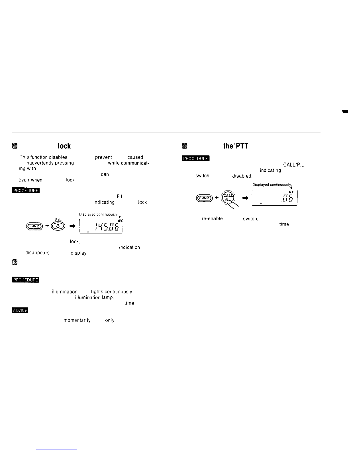
To turn on the lamp momentarily press only the lamp key
Inhibiting
the’PTT
switch
1) Hold down the FUNC key and press the CALL/P.L key.
A PL appears on the display, indicatrng that the PTT
swrtch
has been drsabled.
2) To re-enable the PTT switch. hold down the FUNC key
and press the CALL/P L key a second
trme
47
Page 49
A dditional
Func
tions
(Functions Accessed by
Pressung
Numeric Keys an the Set Mode)
n The following functions are added by switching
to
the set
mode and pressing the numeric keys lndlcated (Refer
to
the
baslc
operation Instructions on page 9
)
Beeper
ONIOFF
83
Inputting the 1 kHz column from the
keyboard
m
1)
Swatch
to the set mode
n
This
function IS used to turn off the beeps
which
normally
Sound
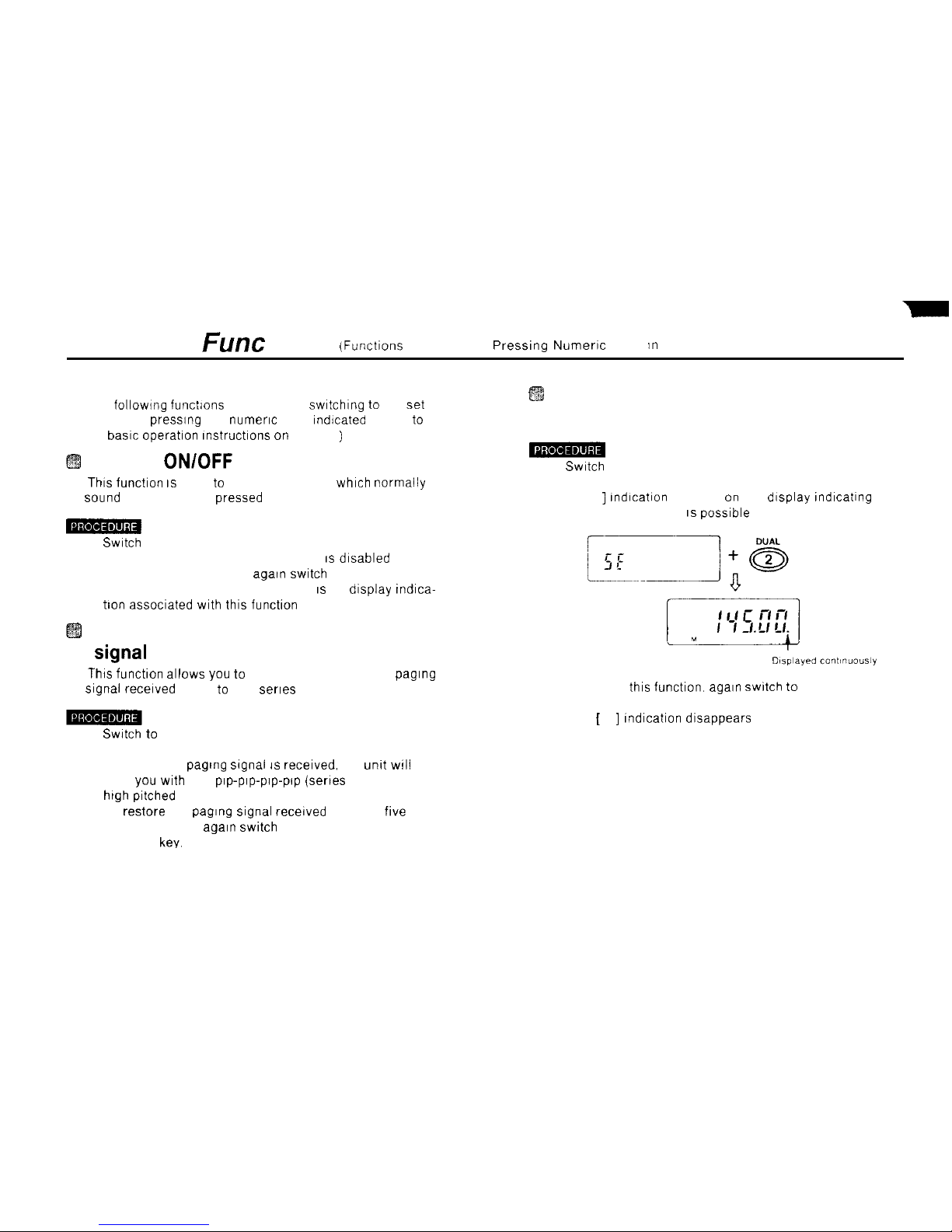
when keys are pressed
2) Press the 2 DUAL key
A [ . ] Indication appears on the display Indicating that
1 kHz column Input IS posslble
1)
Swatch
to the set mode
2) Press the 0 SETISB key The beeper IS dlsabled
3) To re-enable the beeper, again
swltch
to the set mode
and press the 0 SETISB key There IS no display tndica-
tion assoclated with thls function
Changing the length of the paging
Signal
received alarm to one beep
n
This
functlon allows you to reduce the length of the paging
Signal
recelved alarm to one serles of beeps
3) To cancel this function.
again swltch to
the set mode
and press the 2 DUAL key
1)
Swatch to
the set mode
2) Press the 1 PO key
Now, when a paglng
Signal IS
recelved, the
unkt WIII
alert you with one
Pep-Pep-Pep-Pep
(series of repeated
high
pitched beeps).
The [ . ] Indication disappears
3) To restore the paging
Signal
recelved alarm to
five
series of beeps. again
swltch
to the set mode and press
the 1 PO key.
48
Page 50
.
Paging function for
slow-access
repeater stations
n
This
function Increases the Interval between when the PTT
swltch IS
pressed and when fhe paging
Signal IS
transmlt-
ted from 400 to 700 msec.
1)
Swatch
to the set mode
2) Press the 3 SFT key
A
Pep
(short high pitched beep)
Sounds,
Indicating that
the Interval has been Increased to 700 msec
3) To restore the Interval to 400 msec.,
again swltch
to the
set mode and press the 3 SFT key.
A puff (short low pitched beep)
Sounds.
Indicating that
the Interval IS now 400 msec. There IS no display
mdica-
tion
assoclated with this function
(1) It is not possible to
tonfirm
whether this function is on or
Off
by lookrng at the o’ispfay.
(2) When this function IS on. current consumption lncreases
slightly
Auto power off (APO) function
n
Thts
functton prevents the batterles from being discharged
should you forget to swltch the power
Off
after
usmg
the
unit.
n When this function
IS
actlve, a
pip-plp-plp-Pep
warnmg
(repeated high pitched beeps)
Sounds
if the
unit IS
left
unattended for apprtiximately 30
mlnutes.
n Approximately one minute after the warning Sounds. nearly
all
powe< IS tut
off automatically
Thts
functlon IS called auto oower off
(APO)
-
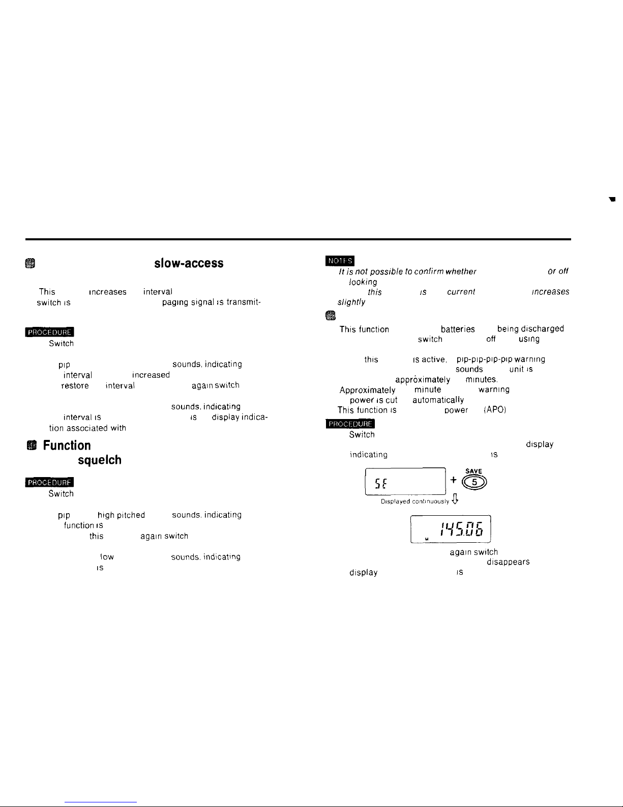
1)
Switch
to the set mode
Function
for suppressing the pop noise
when
squelch
opens
2) Press the 5 SAVE key An AP appears on the display
lndicatlng that auto power off (APO) IS on
1-1
SS
1)
Swatch
to the set mode
2) Press the 4 STEP key
A
Pep
(short
high
pltched beep)
Sounds.
Indicating that
the functlon IS on.
3) To cancel this function.
again switch
to the set mode
and press the 4 STEP key
A puff (short
low
pitched beep)
Sounds.
lnd\cating that
the function IS off
3) To cancel auto power off, again
switch
to the set mode
and press the 5 SAVE key. The AP dlsappears from the
display and auto power off IS canceled
49
Page 51
Recovering from auto power off
Status
n After auto power off
IS
triggered. the display goes blank
To cancel this
Status
(return to normal operatlng Status)
elther press one of the 0 - 9 or A - F keys, or
swtch
power off and then back on
again
Auto power off reduces current consumptmn to the m,ni-
mum level.
However, as current IS st/// fiowing through a
port!on of the
electronvz
orcultry. auto power off
Status IS
not really equlvalent to
swltch~ng
the power oft manuaily
To turn the unit completely off. use the power
swtch
Function
allowing use of the rotary
channel selector even ‘when frequency
leck
is turned on
n Many of the
Operation
keys are disabled when frequency
leck IS on This
function allows
use
of the rotary channel
selector even
when
frequency
leck IS
actlve
1) Swtch to the set mode
2) Press the 6 F L key
Now the rotary channel selector
wll
still work even
if
frequency
leck IS
turned on
3) To cancel thts function.
again switch to
the set mode
and press the 6 F L key A puff (short
low
pitched beep)
Sounds
Indicating that the function IS off
If
the above Operation 1s performed when the unlt IS ,n the
frequency
leck
mode. a boo (lang medfum pltched beepj
Sounds
and the functlon is not actfvated Turn frequency
leck
off before using
th1.s
function
50
Page 52
L
. .
A dditional Func tions
(Funchons Accessed in the Set Mode by Holding Down the FUNC Key and
Pressung
Another Key)
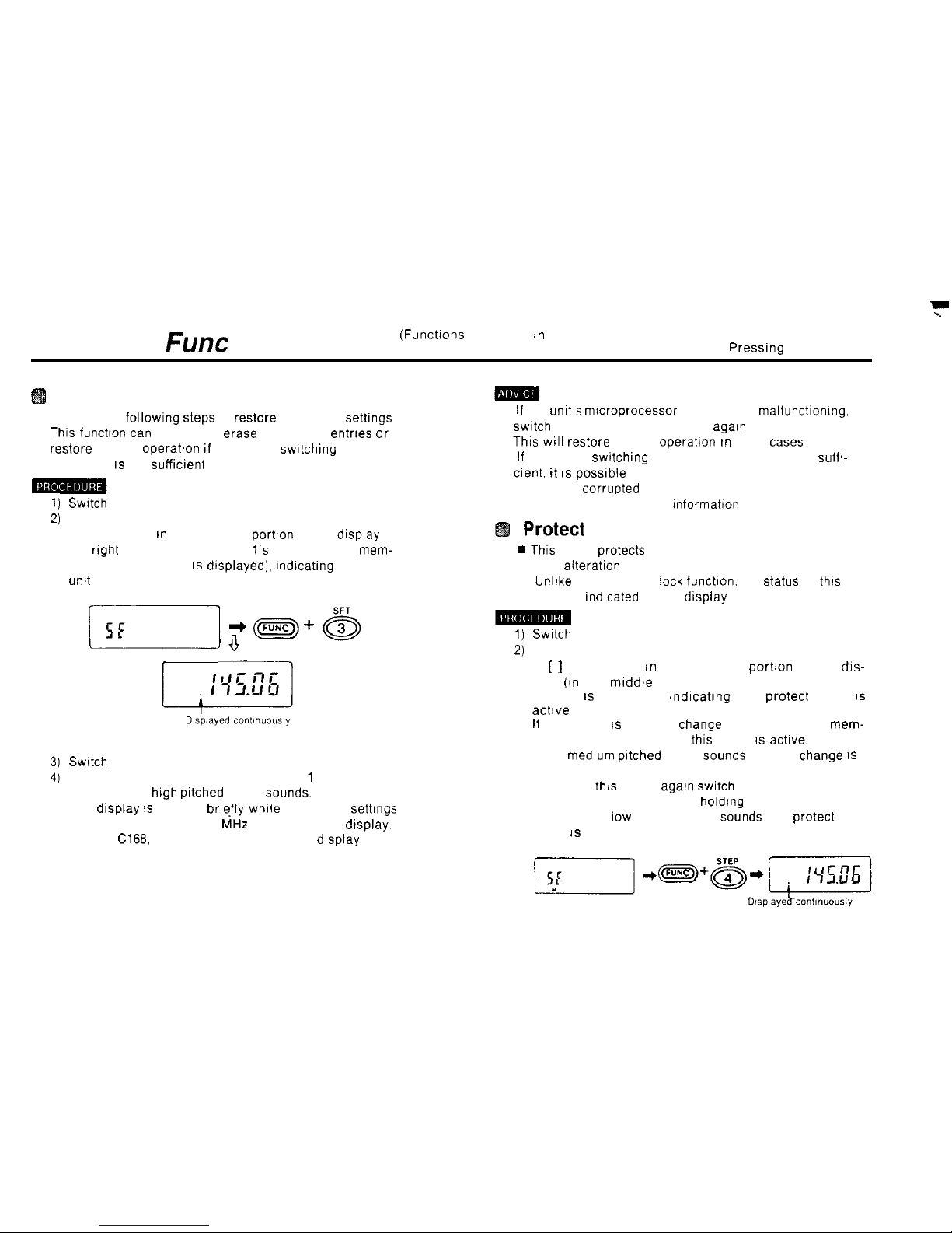
All reset
n Perform the following
Steps
to restore the factory settrngs
Thrs functron tan
be used to erase all memory entrres or to
restore normal
Operation rf
repeatedly
swrtchrng
the power
on and off IS not sufficrent
Swatch
to the set mode
Hold down the FUNC key and press the 3 SFT key
A dot appears tn the lower left
portron
of the display (to
the
rrght
and below where the
1’s
column of the
mem-
ory address number IS dtsplayed).
rndtcatrng
that the
unrt
is ready for all reset.
(1) If the unit’s microprocessor seems to be malfunctronmg.
swrtch
the power off and then on
agarn
Thrs WIII
restore normal
Operation rn
most
cases
(2) If repeatedly swrtching the power on and off is not
suffr-
crent. tt IS possrble
that the contents of the unit’s memory
have been corrupted Perform all reset
Refer to page 61 for more Informatton
Protect
mode
* This
mode protects most of the contents of memory
from alteration
n Unltke the frequency
leck
funchon. the
Status
of
thrs
mode is
rndicated
on the display
1)
Swatch
to the set mode
‘V
2j
r
-7
Switch
to the set mode
Hold down the FUNC key and press the 1 PO key
No pip (short
high prtched
beep)
Sounds.
The drsplay IS blanked brrefly while the factory settrngs
are restored, then 433.00
MHz
appears on the dtsplay.
(On the
Cl66
146.00 MHz appears on the display )
3)
51
Hold down the FUNC key and press the 4 STEP key
A [ ] dot appears rn the lower left portron of the dis-
play
(in
the mrddle of where the memory address
number IS displayed),
indicattng
that protect mode
IS
acttve
If
an attempt IS made to
Change
the contents of a
mem-
ory address number when this mode IS
actrve.
a boo
(long
medrum prtched
beep)
Sounds
and the
Change IS
not allowed
To cancel
thrs
mode.
agarn swrtch
to the set mode and
press the 4 STEP key while
holdrng
down the FUNC key.
A puff (short
low
pitched beep)
Sounds
and protect
mode IS canceled.
Page 53
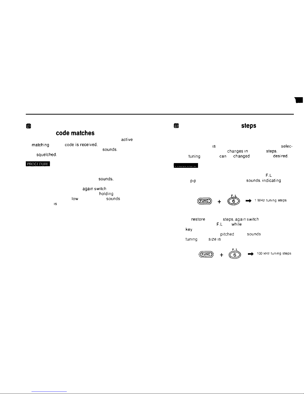
Squelching audio output even if the
paging
code matches
n When this function and the paging function are active and a
matthing paging
code is
recelved, only the pip-pip-pip-pip
alarm (repeated high pitched beeps)
Sounds.
Audio output
is squelched.
1) Switch to the set mode.
2) Hold down the FUNC key and press the 5 SAVE key.
A pip (short high pitched beep)
Sounds,
indicating that
the function is on.
3) To cancel this function, again
switch
to the set mode
and press the 5 SAVE key while holding down the FUNC
key. A puff (short
low
pitched beep)
Sounds
and the
function IS cancelled
Changing the tuning
Steps
used when
the rotary channel selector is turned
with the FUNC key depressed.
n If the FUNC key
IS
held down and the rotary channel selec-
tor turned, the frequency changes In 100 kHz
Steps.
The tuning step size
tan
be changed to 1 MHz if deslred.
1) Switch to the set mode
2) Hold down the FUNC key and press the 6
F.L
key
A
Pep
(short high pitched beep)
Sounds.
Indicating that
the 1 MHz steos have been selected
3) To restore 100 kHz
Steps, again switch
to the set mode
and press the 6
F.L
key while holding down the FUNC
W
A peep (long high pltched beep)
Sounds
and the 100 kHz
tuning step size IS restored
52
Page 54
Clone mode
n
This
functlon allows you to copy the contents of your trans-
cetver’s memory to the memory of another transcelver
“sing DTMF
Codes
H
A maximum of approximately four minutes IS requlred for
coww
1) Swtch to the set mode
2) Hold down the FUNC key and press the 7 T SQ DM key.
No
Pep
(short high pltched beep) Sounds. The clone
mode IS actlvated.
3) Press the PTT
swtch
to transmit the contents of the
transcewer’s memory as DTMF
Codes.
If
such a transmission IS recelved while In the clone
mode, your transcelver’s memory IS overwrltten wlth the
data received
4) When receiving (transmission) IS finished, the
unit
returns to the normal operatlng mode
(1)
While
clone mode is actwe, rf
you
perform another Operation
an
the gaps between when DTMF
Signals
recelved (or
sent).
clone mode is canceled
automatully.
(2) The conVol keys do not function
wh//e
recelvfng (or sending)
in
the clone mode.
(3) If the power
swltch
is turned off while recewmg (or sending)
,n
the clone mode. the
unit’s
proper operatfon cannot be
guaranteed.
(4) The
unlt’s
proper Operation cannot be guaranteed if the
con-
tents
of memory were not copied correctly and complerely.
53
Page 55
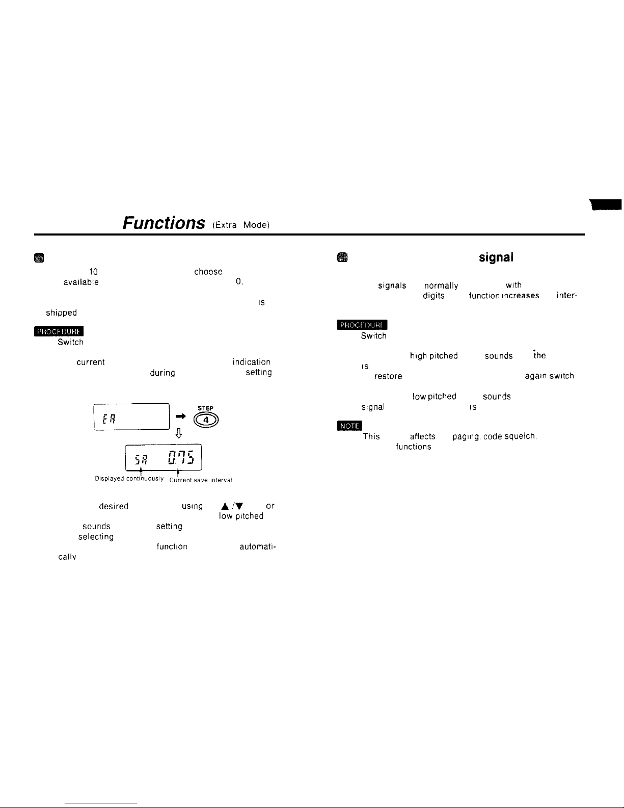
Additional
Functions (Extra Mode)
Selecting the save interval
n There are
IO
save tnterval settings to choose from
The avatlable save intervals are 0 25. 0 5, 0.75. 1 0. 1.5, 2.0.
3.0, 5 0, 7.0 and 10.0 seconds.
n The save interval is set to 0.75 seconds when the unit
IS
shtpped from the factory
1)
Switch
to the extra mode.
2) Press the 4 STEP key.
The current save rnterval is displayed A SA
rndrcatron
appears on the display during the save rnterval setttng
process
3) Select the
desrred
save tnterval
usrng
the A iV keys or
the rotary channel selector. A puff (short
low
pitched
beep)
Sounds
at the 0 75
settrng
4) After selectrng the save tnterval, press the # CL PS key
5) The save tnterval setting funchon is cancelled automatt-
callv
Increasing the DTMF
Signal
transmission interval
n DTMF
Signals
are normally transmttted
wtth
an tnterval of
50 msec. between
drgrts.
This
functron
rncreases the inter-
val to 100 msec
1)
Swatch
to the extra mode
2) Press the 5 SAVE key
A pip (short
high pttched
beep)
Sounds
and
{he
rnterval
IS
set to 100 msec.
3) To restore normal 50 dual msec tnterval, agatn
swrtch
to the extra mode and press the 5 SAVE key
A puff (short
low
pttched beep)
Sounds
and the DTMF
Signal
transmission rnterval IS restored to 50 dual msec.
n
Thts
setting affects the
pagrng.
code squelch. DTMF and
memory functrons
54
Page 56
T
Inputting frequencies from the 100 MHz
column
m
1)
Swatch
to the extra mode
23 Press the 8
RPT
key.
A[.
]
indication appears on the display and frequency
Input from the 100 MHz column IS enabled
How to use charging battery
1) Plug DC adaptor into DC IN plug socket on battery box.
2) Charging time needs
l?-16
hours approximately.
Don7 use other charging Source on charging avoid dam-
aging battery.
3)
To return to the previous
Status.
again
switch
to the
extra mode and press the 7 T SQ DM key The [ .
]
Indication disappears and frequency Input from the
1 MHz column IS restored
55
Page 57
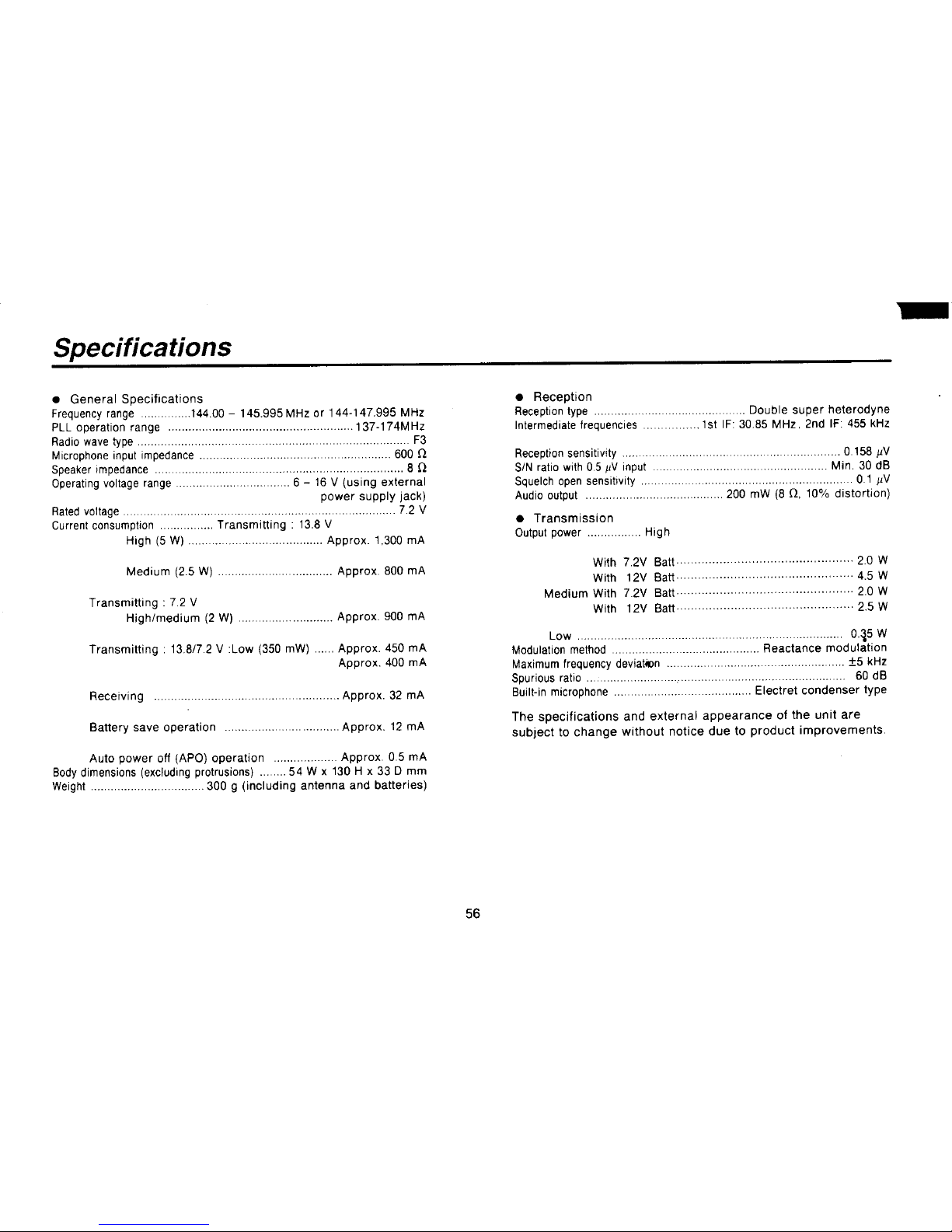
Page 58

Page 59

Page 60

Page 61

Page 62

Page 63

Page 64
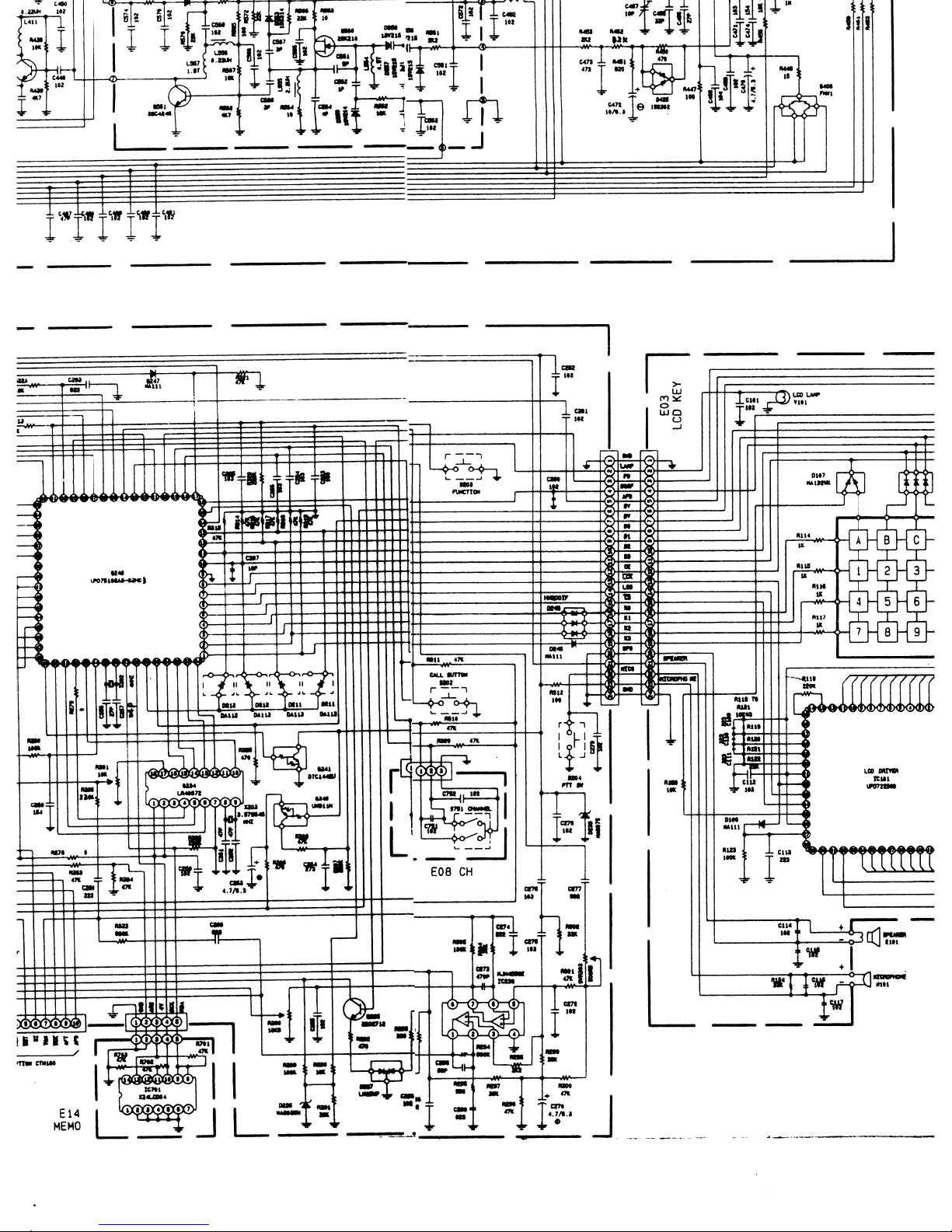
Page 65
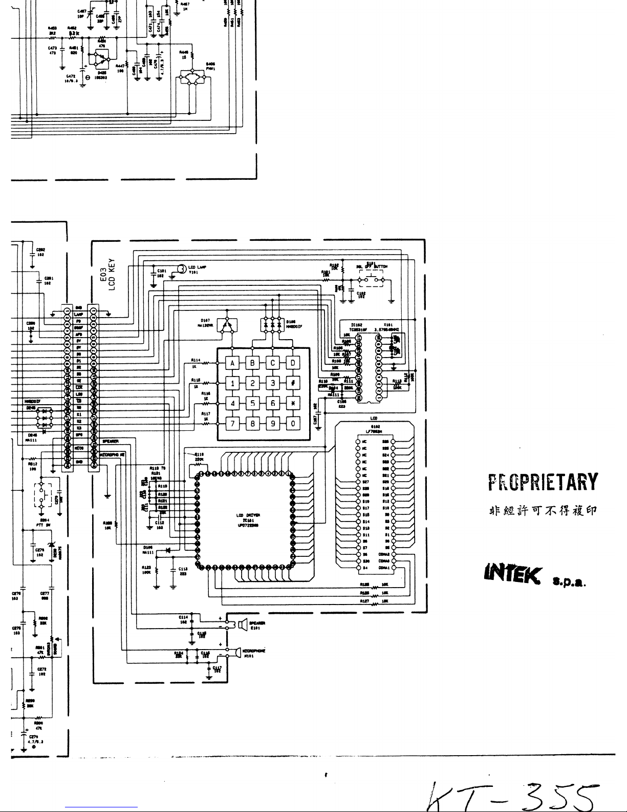
Page 66

INTEK
INTEK
S.P.A.
Direzione.
ammistrazione.
ufficio
vendite
e magazzino
Via G.
Marconi,
16 20090
Segrate
(Ml)
Telefono
02-26950451 (4
linee r.
a. )
Telefax 02-26952185
E-mail
intek.com@intek-com
it /Web
www.intek-com. it
Sede legale viale Bianca Maria. 25 20122 Milano
 Loading...