

Page 1
INSTRUCTION MANUAL
MANUALE DI ISTRUZIONI
PROFESSIONAL 2-WAY RADIO
PC PROGRAMMABLE
PMR446 / 16 CHANNEL
HT-446S
HT-446S/SCR
Page 2
Declaration of Conformity
With the present declaration, we certify that the following products :
INTEK HT-446S
INTEK HT-446S/SCR
comply with all the technical regulations applicable to the above mentioned products
in accordance with the EC Directives 2006/95/EC, 2004/108/EC, 99/5/EC.
Type of product : PMR 446 UHF Transceiver
Details of applied standards : EN 300 296-2, EN 301 489-1/-5,
EN 60065
Manufacturer : INTEK S.R.L.
Via G. Marconi, 16
20090 Segrate, Italy
Tel. 39-02-26950451 / Fax. 39-02-26952185
E-mail : intek.com@intek-com.it
Contact Reference : Armando Zanni
Tel. 39-02-26950451 / Fax. 39-02-26952185
E-mail : intek.com@intek-com.it
Segrate, 02/10/2008 dr. Vittorio Zanetti
(General Manager)
DECLARATION OF CONFORMITY
EC Certificate of Conformity
(to EC Directive 2006/95, 2004/108, 99/5)
NOTICE !
It is recommended to carefully read this owner’s manual before using the product. This will also help the user to
prevent using the radio in violation of the regulations valid in the country where the product is used, as well as to
avoid any possible interferences with other services.
RoHS
2002/95/EC
Page 3

Index . . . . . . . . . . . . . . . . . . . . . . . . . . . . . . . . . . . . . . . . . . . . . . . . . . . . . . . . . . . . . . . . . . . 1
Notice . . . . . . . . . . . . . . . . . . . . . . . . . . . . . . . . . . . . . . . . . . . . . . . . . . . . . . . . . . . . . . . . . . . 1
General information . . . . . . . . . . . . . . . . . . . . . . . . . . . . . . . . . . . . . . . . . . . . . . . . . . . . . . . 2
Unpacking and checking parts - Supplied accessories . . . . . . . . . . . . . . . . . . . . . . . . . . 3
Preliminary Steps . . . . . . . . . . . . . . . . . . . . . . . . . . . . . . . . . . . . . . . . . . . . . . . . . . . . . . . 4-6
Getting acquainted with the product . . . . . . . . . . . . . . . . . . . . . . . . . . . . . . . . . . . . . . . . 7-9
Getting started . . . . . . . . . . . . . . . . . . . . . . . . . . . . . . . . . . . . . . . . . . . . . . . . . . . . . . . . . . 10
Menu Operation . . . . . . . . . . . . . . . . . . . . . . . . . . . . . . . . . . . . . . . . . . . . . . . . . . . . . . . 10-12
Automatic Channel Scanning . . . . . . . . . . . . . . . . . . . . . . . . . . . . . . . . . . . . . . . . . . . . . . 12
Advanced Functions . . . . . . . . . . . . . . . . . . . . . . . . . . . . . . . . . . . . . . . . . . . . . . . . . . . 13-15
Specifications - Optional accessories . . . . . . . . . . . . . . . . . . . . . . . . . . . . . . . . . . . . . . . 16
Frequency / Channels Programming - User Information . . . . . . . . . . . . . . . . . . . . . . . . 17
Index - Notice
- 1 -
English
NOTICE !
This transceiver is programmable via PC, using the dedicated software and the PC interface
cable (optional items). Any programming or modification of the original default setting must be
made by a specialised technician or by an authorised service centre. Some functions of this
transceiver might be programmed in violation of the technical rules in force for the use of the
PMR-446 band. It is the user’s responsibility to check that any modification to the programming
will be done in compliance with the current regulations. Any modification to the product,
alteration of the internal circuit, of the external structure of the radio or any programming in
violation of the current regulations will automatically void the product certification and your right
to use the product. INTEK S.R.L. declines any responsibility concerning any modification of the
product, made by the user or by a third party, after delivery of the product.
NOTICE !
This transceiver has been factory programmed, in order to use the product immediately after
purchase. The programming includes the activation of channels/frequencies in the PMR-446
band, according to the technical rules in force for the use of this band. Please refer to the table
at page 17 for details.
Page 4

Thank you !
Thank you for choosing INTEK for your two-way business radios applications. This user friendly
transceiver will provide you with clear and reliable communications and will keep your professional
activities at peak efficiency. This transceiver incorporates the latest and most advanced technology, so
you will be pleased with its quality and its technical features.
Important notice !
The use of PMR-446 transceivers is subject to the regulations applied in the country where the product
has to be used. As regulations are usually subject to possible modifications, please check the current
regulations in your country with your dealer or local supplier. INTEK does not take any responsibility for
illegal use and operation of this product not in accordance with the regulation of the country where the
product is used.
Safety notice
The user must know and understand the common risks related to the use of transceivers. Do not use
the transceiver in environments at risk of explosion (where there are gas, dusts, smokes, etc.). Do not
use the transceiver in service areas or fuel stations, on board aircrafts, etc.
Cautions
Please observe the following precautions, in order to avoid causing fire, personal injuries or damage to
the radio:
It is suggested that each transmitted message lasts a few minutes only, since very long
transmissions at the maximum transmitter RF output power may overheat the transmitter.
Do not alter or modify in any way your transceiver.
Do not expose the transceiver for a long time to direct sunlight and do not place it close to
heat sources.
Do not expose the transceiver to excessively dusty or damp places, do not place it on
unstable surfaces.
In case of anomalous smell or smoke that leaks out from the transceiver, turn it off immediately
and remove the battery pack. Please contact an authorised service center.
Please do not dispose off used battery with common garbage. Please use the dedicated
disposal containers.
- 2 -
General Information
English
Page 5
Unpacking and Checking Parts - Supplied Accessories
- 3 -
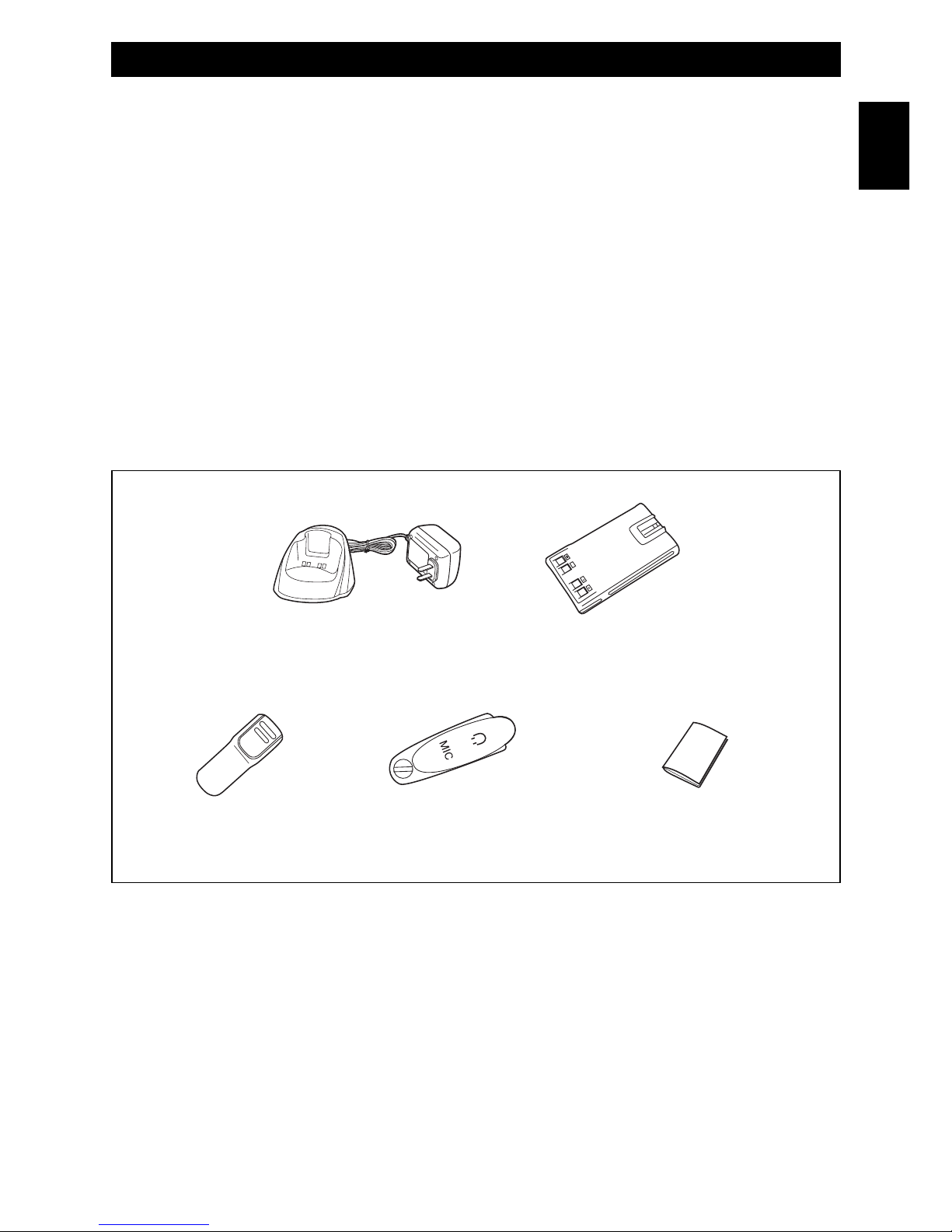
Unpacking and checking parts
Carefully unpack the product. Please identify all the parts listed below, before wasting the packaging. If
any part is missing or if the packaging shows any damage, please contact your dealer immediately.
Supplied accessories
7.4V 1200mAh Li-Ion Rechargeable Battery Pack
Electronic Quick Desk Charger
Belt Clip
Speaker-microphone Jack Cover
User Manual
English
Quick Desk Charger Li-Ion Battery Pack
Belt Clip Speaker-microphone
Jack Cover
User Manual
Page 6
Preliminary Steps
- 4 -
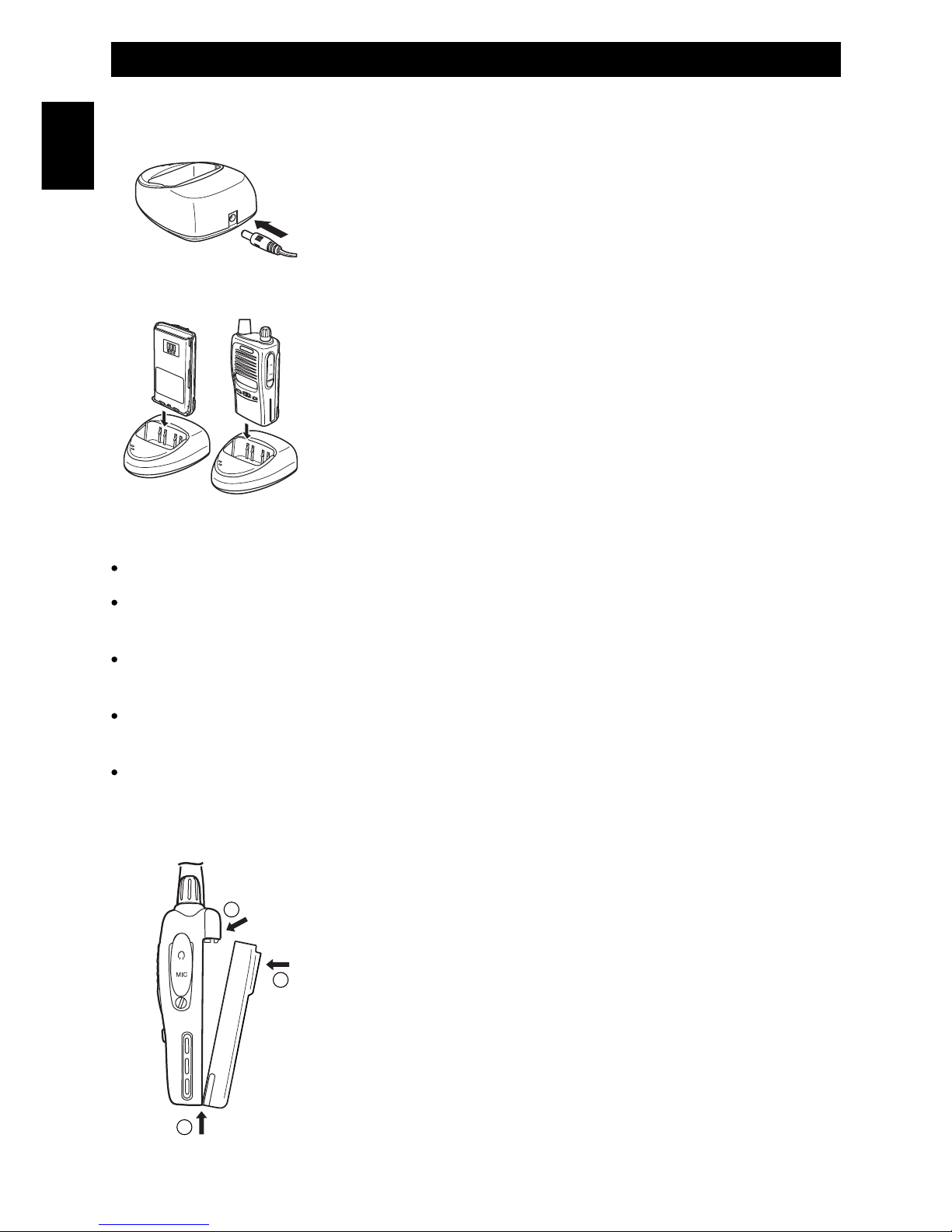
Battery charging
Connect the 230VAC adaptor charger to the desk type battery charger
and to a 230VAC outlet. The Red Led will flash to confirm that the charger
is powered.
Insert the empty battery or the transceiver with the battery pack in the
battery charger. Please make sure that the charging contacts of the radio
are connected with the charging contacts of the charger cradle. The Red
Led will light then the device is ready to begin the charging process. The
charging time depends on the battery condition and capacity. When the
charging process has finished, the Led lights in Green color. Remove the
battery pack or the transceiver from the battery charger and disconnect it
from the AC outlet.
Warning !
The battery is supplied empty and it has to be fully recharged before use.
Some complete cycles of charge/discharge will be necessary in order for the battery to reach a
peak efficiency level.
Please do not charge the battery again when it has just been charged. Otherwise, you may
damage the battery or reduce its life.
The battery charger does not switch OFF automatically when charging is complete, therefore
please remove battery or radio from the charger cradle and disconnect it from the AC outlet.
Do not recharge battery for more than 8 hours, in order to avoid battery overheating.
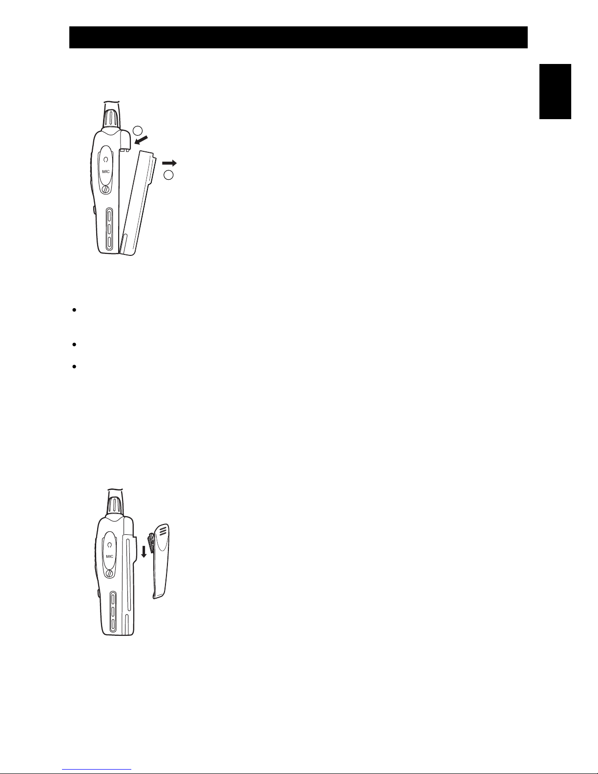
To install the battery
Place the battery pack on the radio as showed in the drawing (item 1).
Push the battery pack forward (item 2) until it is locked on the radio
(item 3).
1
2
3
English
Page 7
To remove the battery
To remove the battery pack, press the battery lock on the radio (item 1) and
push back the battery pack, as showed in the drawing (item 2).
Warning !
Please do not waste used batteries into the environment and do not trash them with the common
garbage. Please use the dedicated case for the collection of used up batteries at your supplier.
Do not attempt to open or remove the battery casing.
Do not short the battery terminals or throw the used batteries into fire.
To install / to remove the belt clip
If necessary, attach the belt clip to the tranceiver, making it slide along the
fit runner placed on the rear side of the battery untill the lock will hook. To
remove the belt clip press the lock and slide the belt clip away from
the battery.
Preliminary Steps
- 5 -
2
1
English
Page 8
- 6 -
Preliminary Steps
English
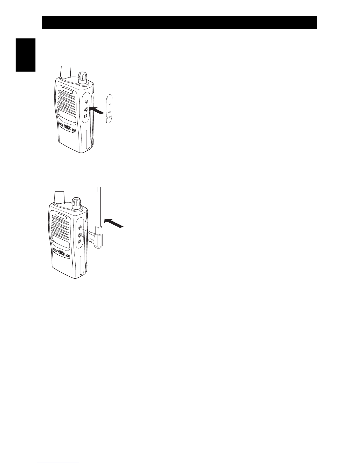
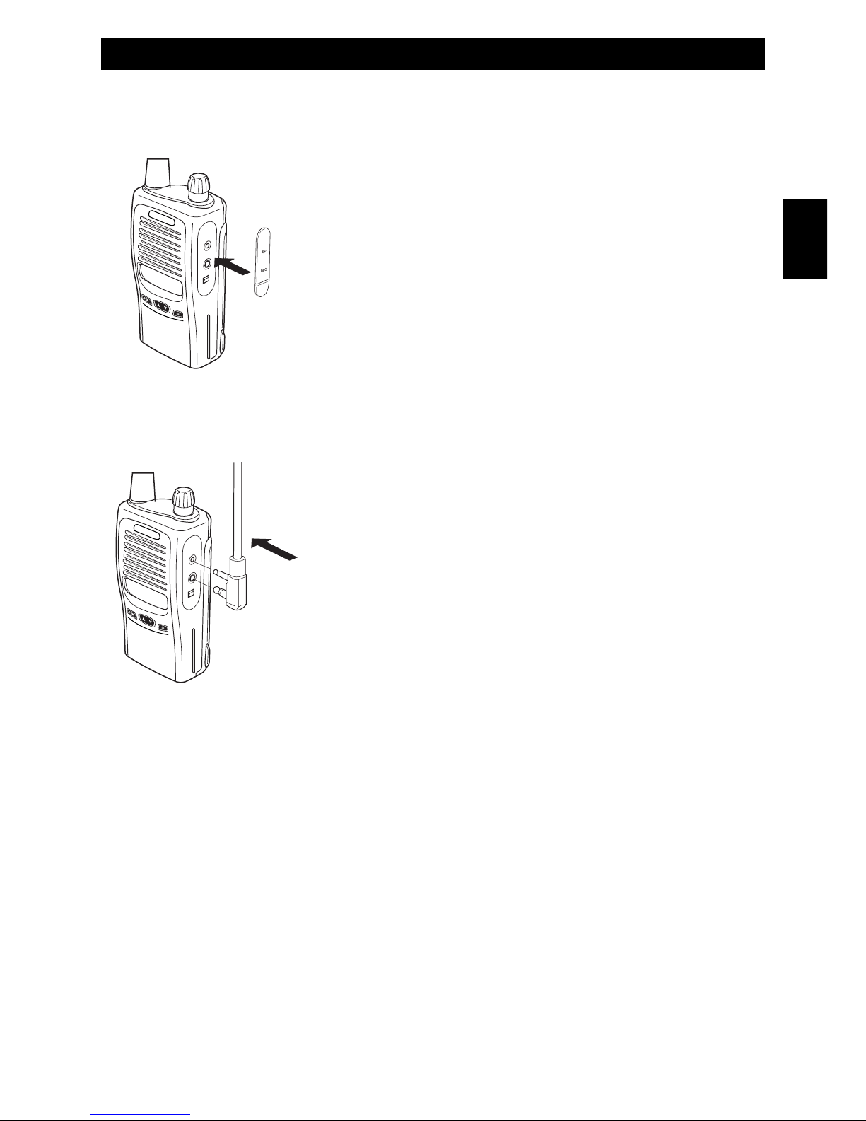
Install the external earset-microphone jack rubber cover.
If an external earset-microphone is not used, please install the earsetmicrophone jack rubber cover.
Install the earset-microphone jack rubber cover as showed on the
drawing. FIx the cover with the supplied screw.
If the earset-microphone jack rubber cover is removed, radio will not
be splash proof.
To install the external microphone (optional)
To install the external microphone, remove the protection cover of the
external microphone/speaker jack. This cover ensures the watertight
integrity of the transceiver (spray-guard) that will not be ensured after
its removing. Insert the connector of the external microphone into the
right jack.
In order to avoid mulfunction or damage to the transceiver, use only
original microphones. Using non original accessories will
authomatically void the warranty.
Warning !
If an external earset-microphone is used, radio will not be splash proof.
Page 9
Getting Acquainted with the Product
- 7 -
English
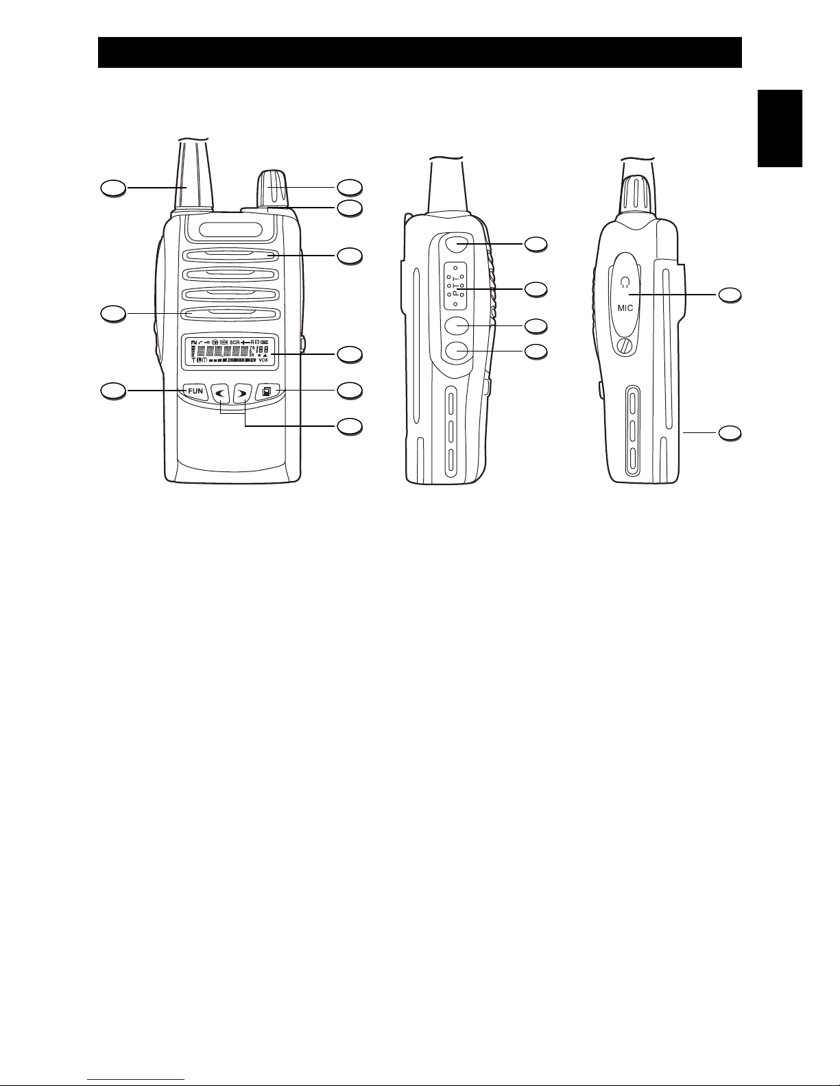
GETTING ACQUAINTED WITH THE PRODUCT
1. Antenna
Fixed non removable rubber flexible antenna.
2. Power ON switch and volume control
Switch on the transceiver turning the knob clockwise or counterclockwise to switch it off.
To increase the volume, turn the knob clockwise or counterclockwise to decrease it.
3. RX/TX LED Indicator
The LED indicator will light in green colour when the radio is receiving a signal and in red colour
during transmission.
4. Speaker
Built-in speaker.
5. LCD Display
Backlighted Dot Matrix LCD Display, provides clear reading and full information on every function
and status of the radio
6. Confirm Key
Press this key to confirm the Menu selections and exit to Stand-by mode.
7. UP/DOWN Keys
Channels and menu operation selection keys.
8. FUN Key
Function key to enter the Menu mode and access several functions of the radio.
1
8
9
2
4
5
6
7
3
10
11
12
13
14
15
Page 10
- 8 -
Getting Acquainted with the Product
9. Microphone
Built-in microphone.
10. Emergency Alarm Key
Press this key to transmit an Emergency Alarm tone. Press the PTT key (11) to close up the alarm.
11. PTT key (Push-To-Talk)
To transmit, press and keep pressed the PTT key (11), then speak into the microphone (9) with
your normal voice. To receive release the PTT key (11).
12. LAMP Key
Rubber key to switch ON and OFF the LCD and keypad backlight function.
13. MONITOR Key
Press this key to open the Squelch, in order to hear the background noise and release it to close
the Squelch.
14. External earset-microphone jack rubber cover
This cover protects the external earset-microphone jack and makes the radio splash proof.
15. Desktop Charger Contacts
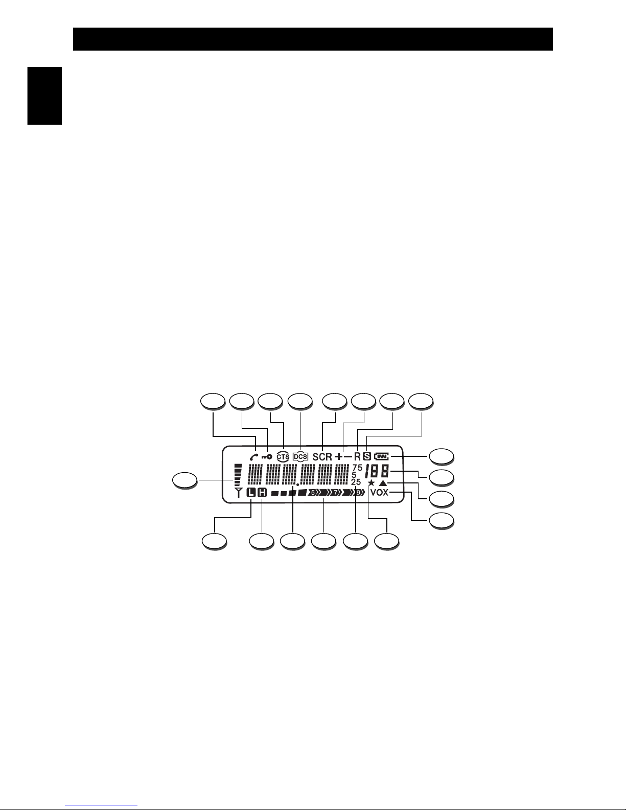
A. ANI Icon
The ANI Icon (A) is lighted when the ANI (Identification Number) function is enables. Please refer
to IDENTIFICATION NUMBER SETUP at page 15.
B. Keypad Lock Icon
The Lock icon (B) is lighted when the keypad lock function has been enabled. Please refer to
KEYBOARD LOCK SETUP at page 11.
C. CTS Icon
The CTS Icon (C) is lighted when the CTCSS function is enabled. Please refer to TONE
SQUELCH function at page 13-14.
English
A CB E GF HD
QR P OST
I
L
N
M
U
LCD DISPLAY
Page 11

- 9 -
Getting Acquainted with the Product
English
D. DCS Icon
The DCS Icon (D) is lighted when the DCS function is enabled. Please refer to TONE SQUELCH
function at page 13-14.
E. SCR Icon (only model HT-446S/SCR)
The SCR Icon (E) is lighted when the Scrambler function is enabled. This function is available
only in model HT-446S/SCR and it may be enabled with the optional PC programming kit.
Before enabling this function, please make sure that local regulations allow the use of this
device.
F.
+ -
Icons
Not available on this model.
G. R Icon
Not available on this model.
H. S Icon
The S Icon (H) is lighted when the Power Save function is enabled. Please refer to POWER SAVE
SETUP at page 14.
I. Battery Level Indicator
It shows the current battery level condition.
L. Numerical Indication
It shows the selected Channel Number and the function number in the Menu Mode.
M. Narrow Band Icon
This icon shows the 12.5KHz channel spacing and it cannot be modified by user.
N. VOX Icon
The VOX icon is lighted when the VOX function has been enabled. Please refer to VOX LEVEL
SETUP at page 12.
O. Channel Scanning Icon
This Icon is lighed when the selected channel is programmed to the scanning list. Please refer to
CHANNEL SCANNING ADDITION/DELETION at page 11.
P. Frequency Reading (25-5-75).
The frequency reading is available only in Memory Mode. Please refer to MODE function at page 13.
Q. RF Digital Meter
It indicates the transmitter RF output power.
R. Dot Matrix Indication
It provides full information on channel and all enabled functions.
S. H Icon
Not available on this model.
T. L Icon
It shows the 0.5W RF output power and it cannot be modified by user.
U. Signal Digital Bar Meter
Indicates the received signal strenght in the receive mode.
Page 12

- 10 -
Getting Started - Menu Operation
English
GETTING STARTED
Power ON
Switch on the transceiver turning the Power/Volume knob (2) clockwise until you hear a click, the
transceiver now is in stand-by mode.
Volume adjustment
To adjust the volume, turn the volume knob (2) while using the MONITOR key (13) to listen to the
background noise of the channels.
Channel selection
Select the desired channel, using the UP/DOWN keys (7).
Transmission
In order to transmit, press the PTT key (11) and speak with your normal voice, keeping the microphone
at about 4 cm from your mouth. The LED indicator (3) will light in red color. Release the PTT (11) key at
the end of transmission.
Receiving
Release the PTT (11) key and properly adjusting volume, you will be able to receive the incoming signals.
When receiving a signal, the LED indicator (13) will light in green colour.
MENU OPERATION
In stand-by status, press FUN key (8) to enter the menu. The numeric indication (L) will show the
selected menu item.
Press the UP/DOWN (7) keys to choose menu items and press the Confirm Key (6) to confirm the
selections and exit to Stand-by mode.
1. Menu function sequence
SQL (Squelch setup) ---> LED (backlight setup) ---> BEP (keypad tone ON/OFF) ---> SCN (channel
scanning add or remove) ---> KY (keypad lock setup) ---> VOX (VOX sensitivity setup) ---> NAM
(channel naming ON/OFF).
2. Key Function in the Menu Mode
FUN Key (8) : enter the menu mode
UP/DOWN Keys (7) : choose menu items
CONFIRM Key (6) : confirm item choice or parameter and exit to Stand-by mode
SQL : Squelch Level Setup
In stand-by status, press the FUN Key (8) to enter the menu mode. The SQL indication (R) and the Menu
item number (L) will appear on the LCD display (5). Press the FUN key (8) to enter the Squelch setup. The
Squelch level will flash on the LCD display. Press the UP/DOWN keys (7) to choose the desired squelch
level from 00 (Squelch opening) to 09. If level 00 is selected, Squelch will be open and you will hear the
background noise. Press the CONFIRM Key (6) to confirm the selection and exit to Stand-by mode or
press the FUN Key (8) to confirm and return to the Menu selection.
Page 13

Menu Operation
- 11 -
English
LED : Backlight Setup
In stand-by status, press the FUN Key (8) to enter the menu mode. The SQL indication and the Menu item
1 (L) will appear on the LCD display (5). Press the UP/DOWN (7) keys several times until the LED
indication (R) and the Menu item 2 (L) appear on the LCD display. Press the FUN key (8) to enter the LED
setup. The LED selected option (AUT, ON or OFF) will flash on the LCD display. Press the UP/DOWN
keys (7) to choose the desired option as follow :
AUT : When this option is selected, the LCD display backlight will be turned on once you press a key.
ON : When this option is chosen, the LCD display backlight will be turned ON automatically.
OFF : When this option is chosen, the LCD display backlight will be turned OFF automatically.
Press the CONFIRM Key (6) to confirm the selection and exit to Stand-by mode or press the FUN Key (8)
to confirm and return to the Menu selection.
However you can turn ON or OFF the LCD backlight anytime, by pressing the LAMP key (12).
BEP : Keypad Tone Setup
When a key is pressed, a beep tone is heard to confirm your command. The user may enable or disable
this keypad program tone. In stand-by status, press the FUN Key (8) to enter the menu mode. The SQL
indication and the Menu item 1 (L) will appear on the LCD display (5). Press the UP/DOWN (7) keys
several times until the BEP indication (R) and the Menu item 3 (L) appear on the LCD display. Press the
FUN key (8) to enter the BEP setup. Press the UP/DOWN keys (7) to select ON (Keypad tone enabled) or
OFF (Keypad tone disabled). Press the CONFIRM Key (6) to confirm the selection and exit to Stand-by
mode or press the FUN Key (8) to confirm and return to the Menu selection.
SCN : Channel Scanning ADDITION / DELETION Setup
Select the channel to be added to the scanning list, using the UP/DOWN keys (7). In stand-by status,
press the FUN Key (8) to enter the menu mode. The SQL indication and the Menu item 1 (L) will appear
on the LCD display (5). Press the UP/DOWN (7) keys several times until the SCNADD (or SCNDEL)
indication (R) and the Menu item 4 (L) appear on the LCD display. Press the FUN key (8) to enter the SCN
setup. Press the UP/DOWN keys (7) keys to choose the following options :
ADD : the selected channel will be added to the scanning list; the Channel Scanning Icon (O) will appear on
the LCD display (5).
DEL : the selected channel will be removed from the scanning list; the Channel Scanning Icon (O) will
disappear from the LCD display (5).
Press the CONFIRM Key (6) to confirm the selection and exit to Stand-by mode or press the FUN Key (8)
to confirm and return to the Menu selection.
KY : Keypad Lock setup
In stand-by status, press the FUN Key (8) to enter the menu mode. The SQL indication and the Menu item
1 (L) will appear on the LCD display (5). Press the UP/DOWN (7) keys several times until the KY
indication (R) and the Menu item 5 (L) appear on the LCD display. Press the FUN key (5) to enter the KY
setup. Press the UP/DOWN keys (7) keys to choose the following options :
AUTO : Automatic Locking. When this option is chosen, the keyboard will be locked automatically when
no operation is performed for about 30 seconds.
MANU : Manual Locking. When this option is chosen, the keyboard cannot be locked automatically.
Press and hold the FUN Key (8) for about 2 seconds to lock or unlock the keypad.
If the Keypad lock function is enabled, the keylock icon (B) appears on the LCD display (5).
Page 14

Press the CONFIRM Key (6) to confirm the selection and exit to Stand-by mode or press the FUN Key (8)
to confirm and return to the Menu selection.
VOX : VOX Level Setup
Your radio is equipped with a user selectable Voice Operated Transmitter function (VOX), that is used
for automatic voice transmission. In this mode, transmission is automatically initiated by speaking into
the microphone (9) and there is no need to push the PTT key (11).
In stand-by status, press the FUN Key (8) to enter the menu mode. The SQL indication and the Menu item
1 (L) will appear on the LCD display (5). Press the UP/DOWN (7) keys several times until the VOX
indication (R) and the Menu item 7 (L) appear on the LCD display. Press the FUN key (8) to enter the VOX
setup. Press the UP/DOWN keys (7) keys to select the desired VOX sensitivity level (from 01 to 09). The
VOX level 09 indicates the highest VOX sensitivity.
Press the CONFIRM Key (6) to confirm the selection and exit to Stand-by mode or press the FUN Key (8)
to confirm and return to the Menu selection.
If the VOX function is enabled, the VOX icon (N) appears on the LCD display (5).
To disable the VOX function, repeat the above procedure and select OFF in the VOX sensitivity level
selection.
NAM : Channel Name ON/OFF
The Channel Naming function allows to assign an alphanumeric name to each channel. The channel
name can be edited only if the Channel Naming function (NAME ?) is enabled with optional
programming kit and it can have up to 6 digits. Please refer to CHANNEL NAMING SETUP at page 15.
The user may enable or disable the NAM function, by proceeding as follow :
in stand-by status, press the FUN Key (8) to enter the menu mode. The SQL indication and the Menu item
1 (L) will appear on the LCD display (5). Press the UP/DOWN (7) keys several times until the NAM
indication (R) and the Menu item 8 (L) appear on the LCD display. Press the FUN key (8) to enter the
NAM setup. Press the UP/DOWN keys (7) keys to select ON (function enabled) or OFF (function disabled).
Press the CONFIRM Key (6) to confirm the selection and exit to Stand-by mode or press the FUN Key (8)
to confirm and return to the Menu selection.
If the NAM function is enabled, the channel name will appear on the LCD display. Otherwise on the LCD
will appear the indication CH- and the selected channel number.
AUTOMATIC CHANNEL SCANNING
To start the Automatic Channel SCAN, press the FUN key (8) and the MONITOR key (13). SCAN will
automatically stop when a signal is detected on one channel, in order to listen to the communication and
SCAN will re-start when no more signal is detected on that channel for a few seconds.
During the scanning process, press the UP/DOWN keys (7) to choose the SCAN direction.
To stop the SCAN function press the PTT (11) or FUN (8) keys.
Menu Operation - Automatic Channel Scanning
- 12 -
English
Page 15

- 13 -
Advanced Functions
ADVANCED FUNCTIONS
These additional functions may be enabled only by using the optional programming kit.
SCR : SCRAMBLER Function (only model HT-446S/SCR)
You can enjoy privacy of communication within your group, by enabling the SCRAMBLER function.
To enable the SCRAMBLER function please proceed as follows :
In stand-by status, press the FUN Key (8) to enter the menu mode. The SQL indication and the Menu item
1 (L) will appear on the LCD display (5). Press the UP/DOWN (7) keys several times until the SCR
indication (R) and the Menu item 6 (L) appear on the LCD display. Press the FUN key (8) to enter the SCR
setup. Press the UP/DOWN keys (7) to select ON (Scrambler function enabled) or OFF (Scrambler
function disabled). Press the CONFIRM Key (6) to confirm the selection and exit to Stand-by mode or
press the FUN Key (8) to confirm and return to the Menu selection. If the SCRAMBLER function is
enabled, the SCR icon (E) appears on the LCD display.
WARNING ! This function is available only in model HT-446S/SCR and it may be enabled with the
optional PC programming kit.
Before enabling this function, please make sure that local regulations allow the use of this device.
MODE : Channel / Memory Mode Switch
In stand-by status, press the FUN Key (8) to enter the menu mode. The SQL indication and the Menu item
1 (L) will appear on the LCD display (5). Press the UP/DOWN (7) keys several times until the MODE
indication (R) and the Menu item 10 (L) appear on the LCD display. Press the FUN key (8) to enter the
MODE setup. Press the UP/DOWN keys (7) to select CH (Channel mode) or MR (Memory Mode). Press
the CONFIRM Key (6) to confirm the selection and exit to Stand-by mode or press the FUN Key (8) to
confirm and return to the Menu selection.
CH : Channel Mode / Channel Naming
MR : Memory Mode / Full frequency readout
Tone Squelch Function (CTCSS) / (DCS)
Any channel may be associated to a programmed private protection CTCSS/DCS tone. A CTCSS/DCS
tone is a sub audible tone which allows to cut off and therefore not to listen to signals transmitted from
other users on the same operating channel.
When you receive a signal which has a tone different from the one which has been programmed on
your radio, you will not listen to this signal. For the same reason, your outgoing messages can only be
received by other radios which have the same tone as yours on that channel.
Note : Even if the use of a CTCSS/DCS tone will protect you from receiving unwanted signals, the
privacy of your transmissions is not guaranteed.
R : CTCSS / DCS RECEIVER SETUP
In stand-by status, press the FUN Key (8) to enter the menu mode. The SQL indication and the Menu item
1 (L) will appear on the LCD display (5). Press the UP/DOWN (7) keys several times until the R indication
(R) and the Menu item 11 (L) appear on the LCD display. Press the FUN key (8) to enter the setup. Press
the MONITOR Key (13) to switch between the CTCSS tone selection and DCS tone selection. In the DCS
tone selection, the LCD display will show the indication RD and the DCS tone number. Press the
UP/DOWN keys (7) keys to select the desired CTCSS / DCS Tone number or select OFF to disable the
function. Press the CONFIRM Key (6) to confirm the selection and exit to Stand-by mode or press the
FUN Key (8) to confirm and return to the Menu selection. In receiving mode, if the CTCSS / DCS functions
are enabled, the CTCSS Icon (C) or DCS Icon (D) will appear on the LCD display (5).
English
Page 16

- 14 -
Advanced Functions
T : CTCSS / DCS TRANSMITTER SETUP
In stand-by status, press the FUN Key (8) to enter the menu mode. The SQL indication and the Menu item
1 (L) will appear on the LCD display (5). Press the UP/DOWN (7) keys several times until the T indication
(R) and the Menu item 12 (L) appear on the LCD display. Press the FUN key (8) to enter the T setup.
Press the MONITOR Key (13) to switch between the CTCSS tone selection and DCS tone selection.
In the DCS tone selection, the LCD display will show the indication TD and the DCS tone number. Press
the UP/DOWN keys (7) keys to select the desired CTCSS / DCS Tone number or select OFF to disable the
function. Press the CONFIRM Key (6) to confirm the selection and exit to Stand-by mode or press the
FUN Key (8) to confirm and return to the Menu selection. In transmitting mode, if the CTCSS / DCS
functions are enabled, the CTCSS Icon (C) or DCS Icon (D) will appear on the LCD display (5).
C : CTCSS / DCS SETUP (RECEIVING AND TRANSMITTING MODES)
In stand-by status, press the FUN Key (8) to enter the menu mode. The SQL indication and the Menu item
1 (L) will appear on the LCD display (5). Press the UP/DOWN (7) keys several times until the C indication
(R) and the Menu item 13 (L) appear on the LCD display. Press the FUN key (8) to enter the C setup.
Press the MONITOR Key (13) to switch between the CTCSS tone selection and DCS tone selection. In the
DCS tone selection, the LCD display will show the indication RD and the DCS tone number. Press the
UP/DOWN keys (7) keys to select the desired CTCSS / DCS Tone number or select OFF to disable the
function. Press the CONFIRM Key (6) to confirm the selection and exit to Stand-by mode or press the
FUN Key (8) to confirm and return to the Menu selection. If the CTCSS / DCS functions are enabled, the
CTCSS Icon (C) or DCS Icon (D) will appear on the LCD display (5).
SAV : Power Save Setup
This function reduces the battery consumption when no signal is received or when no operation is
performed (it means when no key is pressed, no switch is turned on/off). The user may enable or disable
this function.
In stand-by status, press the FUN Key (8) to enter the menu mode. The SQL indication and the Menu item
1 (L) will appear on the LCD display (5). Press the UP/DOWN (7) keys several times until the SAV
indication (R) and the Menu item 14 (L) appear on the LCD display. Press the FUN key (8) to enter the
SAV setup. Press the UP/DOWN keys (7) to select ON (Power Save enabled) or OFF (Power Save
disabled). Press the CONFIRM Key (6) to confirm the selection and exit to Stand-by mode or press the
FUN Key (8) to confirm and return to the Menu selection.
SCAN : Automatic Scanning Setup
In stand-by status, press the FUN Key (8) to enter the menu mode. The SQL indication and the Menu item
1 (L) will appear on the LCD display (5). Press the UP/DOWN (7) keys several times until the SCAN
indication (R) and the Menu item 15 (L) appear on the LCD display. Press the FUN key (8) to enter the
SCN setup. Press the UP/DOWN keys (7) to select CO (Carrier Scan) or TO (Time Scan). Press the
CONFIRM Key (6) to confirm the selection and exit to Stand-by mode or press the FUN Key (8) to confirm
and return to the Menu selection.
To start the Automatic Channel SCAN, press the FUN key (8) and the MONITOR key (13).
CO (Carrier Scan) : If this option is selected, SCAN will automatically stop when a signal is detected on
one channel, in order to listen to the communication and SCAN will re-start when no more signal is
detected on that channel for a few seconds.
TO (Time Scan) : If this option is selected, SCAN will automatically stop when a signal is detected on one
channel, and re-start automatically after a few seconds.
English
Page 17

- 15 -
Advanced Functions
During the scanning process, press the UP/DOWN keys (7) to chosose the SCAN direction.
To stop the SCAN function press the PTT (11) or FUN (8) keys.
TOT : Time-Out-Timer Setup
This function has two purposes :
1. to allow, after a set time, to listen to other urgent calls.
2. avoid to transmit for an endless time, in order to prevent overheating or damage to the
transceiver. After a programmable time of 30-240 seconds of uninterrupted transmission, the
transceiver automatically stops the transmission emitting a warning tone (pre-set function). To stop the
warning tone, release the PTT key (11). To restart the transmission, press again the PTT key (11).
To set up this function, in stand-by status, press the FUN Key (8) to enter the menu mode. The SQL
indication and the Menu item 1 (L) will appear on the LCD display (5). Press the UP/DOWN (7) keys
several times until the TOT indication (R) and the Menu item 16 (L) appear on the LCD display. Press the
FUN key (8) to enter the TOT setup. Press the UP/DOWN keys (7) to select the desired time from 30 to
240 seconds or select OFF to disable the function. Press the CONFIRM Key (6) to confirm the selection
and exit to Stand-by mode or press the FUN Key (8) to confirm and return to the Menu selection.
ANI : Identification Number Setup
In stand-by status, press the FUN Key (8) to enter the menu mode. The SQL indication and the Menu item
1 (L) will appear on the LCD display (5). Press the UP/DOWN (7) keys several times until the ANI
indication (R) and the Menu item 17 (L) appear on the LCD display. Press the FUN key (8) to enter the ANI
setup. Press the UP/DOWN keys (7) to select ON (function enabled) or OFF (function disabled). Press the
CONFIRM Key (6) to confirm the selection and exit to Stand-by mode or press the FUN Key (8) to confirm
and return to the Menu selection.
BUS : Busy Channel Lockout Setup
In stand-by status, press the FUN Key (8) to enter the menu mode. The SQL indication and the Menu item
1 (L) will appear on the LCD display (5). Press the UP/DOWN (7) keys several times until the BUS
indication (R) and the Menu item 19 (L) appear on the LCD display. Press the FUN key (8) to enter the
BUS setup. Press the UP/DOWN keys (7) to choose the desired option as follow :
CAR : when the radio is receiving a signal, you can' t transmit at the same time.
QDT : when the radio is receiving a signal with the same CTCSS/DCS code, you can' t transmit at the
same time.
OFF : the function is disabled.
Press the CONFIRM Key (6) to confirm the selection and exit to Stand-by mode or press the FUN Key (8)
to confirm and return to the Menu selection.
NAME ? : Channel Naming Setup
In stand-by status, press the FUN Key (8) to enter the menu mode. The SQL indication and the Menu item
1 (L) will appear on the LCD display (5). Press the UP/DOWN (7) keys several times until the NAME ?
indication (R) and the Menu item 20 (L) appear on the LCD display. Press the FUN key (8) to edit the
channel name; the first digit will blink on the LCD display. Press the UP/DOWN keys (7) to select the
desired number or letter of the flashing digit and press the CONFIRM key (6) to edit the next digit. The
selected digit will start flashing.
Press the FUN key (8) to confirm the edited channel name and press the CONFIRM key (6) to exit to
Stand-by mode.
English
Page 18

Specifications - Optional Accessories
- 16 -
SPECIFICATIONS
General
Frequency 446.00625 - 446.09375 MHz
Channels 16 / 199
Channel spacing 12.5 KHz
DC input voltage 7.4 VDC
Operating temperature -20/+55°
Dimensions mm 58 x 124 x 38
Weight 230 gr. (with battery pack)
Receiver
Sensitivity (12dB Sinad) 0.25 µV
Audio output 500mW
Transmitter
RF output power 0.5W ERP
Modulation FM
Spurious & Harmonics in compliance with the R&TTE regulations
OPTIONAL ACCESSORIES
- LN-865 High capacity Li-Ion 7.2V 1800mAh rechargeable battery pack
- LP-865 High capacity Li-Poly 7.4V 1800mAh rechargeable battery pack
- KME-315 External Earset-Microphone with tie clip
- KME-614 External Earset-Microphone with adjustable ear hook
- KME-801 External Earset-Microphone for security and bodyguard
- KME-100A External Earset-Microphone with tie clip
- KME-200A External Earset-Microphone with flexible boom mic and tie clip
- KME-H115 External Speaker-Microphone (light duty)
- KST-301 External Speaker-Microphone (heavy duty)
- CDLS-HTHX Programming Kit (PC interface cable and software CD)
English
Page 19

Frequency / Channels Programming - User Information
- 17 -
CHANNEL
FREQUENCY
TX
FREQUENCY
RX
CTCSS / DCS
TONE
1
2
3
4
5
6
7
8
9
10
11
12
13
14
15
16
446.00625
446.01875
446.03125
446.04375
446.05625
446.06875
446.08125
446.09375
446.00625
446.01875
446.03125
446.04375
446.05625
446.06875
446.08125
-
446.00625
446.01875
446.03125
446.04375
446.05625
446.06875
446.08125
446.09375
446.00625
446.01875
446.03125
446.04375
446.05625
446.06875
446.08125
-
NO
NO
NO
107.2
110.9
114.8
118.8
123.0
127.3
131.8
136.5
141.3
146.2
123.0
156.7
-
FREQUENCY / CHANNELS PROGRAMMING (factory default programming)
User Information
in accordance with art. 13 of the Legislative Decree of 25th July 2005, no. 15 ”Implementation of Directives 2002/95/EC,
2002/96/EC and 2003/108/EC, relative to reduction of the use of hazardous substances in electrical and electronic
equipment, in addition to waste disposal”.
The crossed bin symbol shown on the equipment indicates that at the end of its working life the product must
be collected separately from other waste.
The user must therefore take the above equipment to the appropriate differentiated collection centres for
electronic and electro technical waste, or return it to the dealer when purchasing a new appliance of
equivalent type, in a ratio of one to one.
Appropriate differentiated waste collection for subsequent recycling, treatment and environment-friendly disposal of the
discarded equipment helps to prevent possible negative environmental and health effects and encourages recycling of
the component materials of the equipment.
Illegal disposal of the product by the user will be punished by application of the administrative fines provided for by the
legislative decree no. 22/1997 (article 50 and following of the legislative decree no. 22/1997).
English
Page 20

Indice - Importante . . . . . . . . . . . . . . . . . . . . . . . . . . . . . . . . . . . . . . . . . . . . . . . . . . . . . . . 18
Informazioni per l' utente . . . . . . . . . . . . . . . . . . . . . . . . . . . . . . . . . . . . . . . . . . . . . . . . . . 19
Disimballaggio e verifica delle parti - Accessori forniti . . . . . . . . . . . . . . . . . . . . . . . . . 20
Preparazione . . . . . . . . . . . . . . . . . . . . . . . . . . . . . . . . . . . . . . . . . . . . . . . . . . . . . . . . . 21-23
Familiarizzare con il prodotto . . . . . . . . . . . . . . . . . . . . . . . . . . . . . . . . . . . . . . . . . . . 24-27
Operazioni di base . . . . . . . . . . . . . . . . . . . . . . . . . . . . . . . . . . . . . . . . . . . . . . . . . . . . . . . 27
Utilizzo del menu . . . . . . . . . . . . . . . . . . . . . . . . . . . . . . . . . . . . . . . . . . . . . . . . . . . . . . 27-30
Funzioni supplementari . . . . . . . . . . . . . . . . . . . . . . . . . . . . . . . . . . . . . . . . . . . . . . . . 30-33
Specifiche tecniche . . . . . . . . . . . . . . . . . . . . . . . . . . . . . . . . . . . . . . . . . . . . . . . . . . . . . . 34
Accessori opzionali . . . . . . . . . . . . . . . . . . . . . . . . . . . . . . . . . . . . . . . . . . . . . . . . . . . . . . 34
Programmazione canali - Avviso agli utenti . . . . . . . . . . . . . . . . . . . . . . . . . . . . . . . . . . 35
Avvertenze importanti . . . . . . . . . . . . . . . . . . . . . . . . . . . . . . . . . . . . . . . . . . . . . . . . . . . . 36
Garanzia limitata . . . . . . . . . . . . . . . . . . . . . . . . . . . . . . . . . . . . . . . . . . . . . . . . . . . . . . . . . 36
Indice - Introduzione
- 18 -
IMPORTANTE !
Questo ricetrasmettitore è programmabile tramite PC, utilizzando l’apposito software e cavetto
di interfaccia (opzionali). L’eventuale programmazione o modifica della programmazione
esistente deve essere eseguita da un tecnico specializzato o da un centro di assistenza
autorizzato. Alcune funzioni del ricetrasmettitore potrebbero essere programmate in violazione
delle norme tecniche in vigore per l’utilizzo della banda PMR- 446. E’ responsabilità dell’utente
verificare che eventuali modifiche nella programmazione delle funzioni del ricetrasmettitore
siano conformi a quanto previsto dalle norme tecniche in vigore. Modifiche al prodotto,
manomissioni, alterazione delle regolazioni interne o delle strutture esterne della radio e
programmazioni in violazione delle norme di legge fanno decadere le certificazioni e
omologazioni del prodotto ed il diritto all’utilizzo dello stesso.
INTEK s.r.l. declina qualsiasi responsabilità relativamente a modifiche della programmazione
del ricetrasmettitore, eseguite dall’utente o da terzi, dopo la consegna del prodotto.
IMPORTANTE !
Questo ricetrasmettitore è stato pre-programmato in origine, al fine di consentire all’utente
l’utilizzo immediato del prodotto dopo l’acquisto. La programmazione eseguita comprende
l’attivazione di canali/frequenze in banda PMR-446, nel rispetto delle norme tecniche in vigore
per l’utilizzo di questa banda. Per i dettagli riferirsi alla tabella a pag. 24.
Italiano
Page 21

Grazie !
Vi ringraziamo per aver scelto INTEK per applicazioni civili. Siamo certi che questo ricetrasmettitore di
facile uso vi consentirà di comunicare in modo affidabile e di svolgere le vostre attività professionali con
la massima efficienza. Questo ricetrasmettitore incorpora la più avanzata tecnologia e sarete soddisfatti
del suo livello di qualità e delle sue caratteristiche tecniche.
Avviso importante per l' utente !
L’utilizzo dei ricetrasmettitori PMR 446 è regolato dalle norme di legge in vigore. Poiché le norme
stesse sono soggette a possibili variazioni, prima di utilizzare gli apparecchi, si raccomanda di
informarsi presso il proprio rivenditore o fornitore verificando gli eventuali adempimenti da osservare.
INTEK declina qualsiasi responsabilità relativamente ad un uso degli apparecchi non autorizzato o non
conforme alle norme di legge.
Sicurezza
L’utente deve conoscere e comprendere i rischi comuni legati all’uso di apparecchi ricetrasmittenti. Non
utilizzate mai il ricetrasmettitore in ambienti a rischio di esplosione (in presenza di gas, polveri, fumi,
etc.). Non utilizzare inoltre il ricetrasmettitore nelle aree di servizio o distributori di carburante.
Precauzioni
Si consiglia di osservare le seguenti precauzioni, al fine di evitare incendi, ferite personali e danni al
ricetrasmettitore:
Si suggerisce di trasmettere per alcuni minuti in quanto trasmissioni molto lunghe o alla massima
potenza del trasmettitore potrebbero surriscaldare lo stesso.
Non manomettere o modificare in alcun modo il ricetrasmettitore.
Non esporre il ricetrasmettitore per lungo tempo alla luce solare diretta e non porlo vicino a fonti
di calore.
Non porre il ricetrasmettitore in luoghi eccessivamente polverosi o umidi, inoltre non porlo su
superfici instabili.
Se sentite un odore anomalo o se vedete del fumo fuoriuscire dal ricetrasmettitore, spegnetelo
immediatamente e rimuovete il pacco batteria. Quindi contattate un centro di assistenza
autorizzato.
Non gettate batterie usate nella spazzatura. Utilizzate solo gli appositi contenitori per lo
smaltimento.
- 19 -
Informazioni per l' utente
Italiano
Page 22

Disimballaggio e verifica delle parti - Accessori forniti
- 20 -
Disimballaggio e verifica delle parti
Disimballate accuratamente il ricetrasmettitore. Si raccomanda di identificare tutte le parti elencate nella
tabella seguente, prima di eliminare l’imballo. Se vi sono stati danni o mancanze durante la spedizione,
contattate immediatamente il vostro fornitore.
Accessori forniti
Pacco batteria Li-Ion 1200mAh 7.4V
Caricabatterie rapido elettronico da tavolo 230VAC
Clip da cintura
Chiusura per presa earset-mic
Manuale d' uso
Caricabatterie rapido da tavolo Pacco batterie Li-Ion
Clip da cintura Chisura in gomma per
presa earset-mic
Manuale d' uso
Italiano
Page 23

Ricarica della batteria
Collegare l’adattatore 230V alla presa posta sul retro del caricatore da
tavolo, come mostrato dal disegno. Collegare l' adattatore alla presa
230VAC. Il LED inizierà a lampeggiare in colore rosso.
Inserire la batteria scarica o il ricetrasmettitore con la batteria installata nel
caricabatteria. Assicurarsi che i terminali della batteria siano a contatto
con quelli dei caricatore. Il LED smetterà di lampeggiare e rimarrà acceso
in colore rosso, quindi l’apparecchio si predispone per iniziare la ricarica
automatica della batteria. Il tempo di ricarica dipende dallo stato di carica
e dalla capacità della batteria. Quando la ricarica è stata completata, il
LED sarà acceso in colore verde. A questo punto rimuovere la batteria o il
ricetrasmettitore dal caricatore e scollegare quest’ultimo dalla rete
elettrica.
Avvertenze !
La batteria viene fornita scarica e deve essere quindi ricaricata prima dell’uso.
Sono necessari alcuni cicli completi di carica/scarica affinché la batteria raggiunga il massimo
livello di efficienza.
La batteria non deve essere ricaricata nuovamente se è già stata completamente caricata.
Diversamente, la vita della batteria può diminuire o la stessa essere danneggiata.
Il caricabatterie non si spegne automaticamente dopo la ricarica pertanto rimuovere la batteria o il
ricetrasmettitore dal caricatore e scollegare quest’ultimo dalla rete elettrica.
Non superare le 8 ore di ricarica, per evitare il danneggiamento della batteria.
Installare la batteria
Far coincidere le 3 guide della batteria con le 3 scanalature corrispondenti
poste alla base del ricetrasmettitore, come mostrato nel disegno (punto 1).
Spingere la batteria sul retro del ricetrasmettitore (punto 2) fino a quando
il blocco posto nella parte alta della radio si aggancia e blocca la batteria
(punto 3).
Preparazione
- 21 -
1
2
3
Italiano
Page 24

2
1
Rimuovere la batteria
Per rimuovere la batteria premere sul blocco posto nella parte alta della
radio (punto 1) ed estrarla dalla stessa come mostrato nel disegno
(punto 2).
Avvertenze !
Non disperdere batterie esaurite nell’ambiente e non gettarle tra i rifiuti ordinari. Utilizzate gli
appositi contenitori per la raccolta delle batterie usate o restituite le batterie da eliminare al vostro
fornitore.
Non tentare mai di rimuovere l’involucro della batteria.
Non cortocircuitare i teminali della batteria e non gettare quest' ultima nel fuoco.
Installare la clip da cintura
Se necessario, applicare la clip da cintura al ricetrasmettitore, facendola
scivolare nell’apposita scanalatura posta sul retro della batteria fino a
quando il blocco metallico si aggancia. Per rimuovere la clip premere sul
blocco metallico e farla scivolare via dalla batteria.
Preparazione
- 22 -
Italiano
Page 25
Installare la chiusura per la presa earset-mic
Se non si utilizza un microfono-altoparlante esterno, coprire la presa
con il coperchio in gomma in dotazione.
Applicare il coperchio come mostrato nel disegno e fissarlo
utilizzando la vite in dotazione.
Questa copertura assicura inoltre la tenuta stagna (anti spruzzo) del
ricetrasmettitore, che non sarà quindi più garantita dopo la sua
rimozione.
Installare un microfono esterno (opzionale)
Per poter installare il microfono esterno, occorre prima rimuovere la
copertura fissata a protezione della presa per microfono/altoparlante
esterno.
Inserire il connettore del microfono esterno nell’apposita presa.
Per evitare malfunzionamenti o danni al ricetrasmettitore, utilizzare
esclusivamente microfoni originali. L’utilizzo di accessori diversi da
quelli originali causa automaticamente la perdita del diritto alla
garanzia.
Attenzione :
Se si utilizza un microno esterno, il ricetrasmettitore non è più a tenuta stagna.
Preparazione
- 23 -
Italiano
Page 26

Familiarizzare con il prodotto
- 24 -
FAMILIARIZZARE CON IL PRODOTTO
1. Antenna
Antenna flessibile in gomma non rimuovibile.
2. Interruttore ON-OFF / Comando di volume
Ruotare la manopola in senso orario per accendere il ricetrasmettitore e in senso antiorario per
spegnerlo. Ruotare la manopola in senso orario per aumentare il volume e in senso antiorario per
diminuirlo.
3. Indicatore LED RX/TX
Questo indicatore LED bi-colore rosso-verde è acceso in colore verde quando la radio è in
modalità ricezione e in colore rosso quando è in modalità trasmissione.
4. Altoparlante
Altoparlante entro contenuto.
5. Display LCD
Display LCD a matrice di punti, retroilluminato, consente la visualizzazione completa di tutte le
funzioni attivate e di tutte le informazioni impostabili dall' utente.
6. Tasto CONFERMA
Nelle operazioni del menu, consente di confermare le selezioni e ritornare in modalità Stand-by.
7. Tasti UP/DOWN
Tasti per la selezione dei canali. Nelle operazioni del menu consentono la selezione delle varie
funzioni.
8. Tasto FUN (Menu)
Tasto funzione per l' accesso al Menu e alle varie funzioni della radio.
1
8
9
2
4
5
6
7
3
10
11
12
13
14
15
Italiano
Page 27

Familiarizzare con il prodotto
- 25 -
9. Microfono
Microfono entro contenuto.
10. Tasto Allarme di emergenza
Premere questo tasto per inviare un allarme sonoro di emregenza. Premere il tasto PTT (11) per
cessare l' allarme.
11. Tasto PTT (Push-To-Talk)
Per effettuare una chiamata, premere e tenere premuto il tasto PTT (11), quindi parlare nel
microfono (9) con un volume di voce normale. Rilasciare il tasto PTT (11) per ricevere.
12. Tasto LAMP
Premere questo tasto per attivare l' illuminazione del display LCD (5). Ripremere il tasto per
disattivarla.
13. Tasto MONITOR
Premere questo tasto per aprire lo Squelch e ascoltare quindi il rumore di fondo. Rilasciare il
tasto Monitor (13) per richiudere lo Squelch.
14. Copertura della presa Earset-mic
Coperchio di gomma in dotazione che consente di coprire la presa per microfono esterno e quindi
di rendere la radio a tenuta stagna.
15. Contatti per caricabatterie da tavolo
A CB E GF HD
QR P OST
I
L
N
M
U
LCD DISPLAY
A. Icona ANI
L' icona ANI (A) è accesa quando la funzione ANI (Identification Number) è attiva. Fare riferimento
al paragrafo ANI a pag. 33.
B. Icona blocco tastiera (Key Lock)
L' icona (B) è accesa quando è inserito il blocco della tastiera. Fare riferimento al paragrafo
IMPOSTAZIONE BLOCCO TASTIERA a pag. 29.
Italiano
Page 28

Familiarizzare con il prodotto
- 26 -
C. Icona CTS
L' icona CTS (C) è accesa quando è attiva la funzione CTCSS. Fare riferimento al paragrafo
IMPOSTAZIONE DELLA FUNZIONE TONE SQUELCH a pag. 30-31.
D. Icona DCS
L' icona DCS (D) è accesa quando è attiva la funzione DCS. Fare riferimento al paragrafo
IMPOSTAZIONE DELLA FUNZIONE TONE SQUELCH a pag. 30-31.
E. Icona SCR (solo modello HT-446S/SCR)
L' icona SCR (E) è accesa quando la funzione SCRAMBLER è attivata. Questa funzione è
disponibile solo nel modello HT-446S/SCR e può essere attivata tramite kit di programmazione
opzionale. Prima di abilitare questa funzione, assicurarsi che le norme tecniche in vigore nel paese
di utilizzo ne consentano l' uso.
F. Icone
+ -
Non disponibili in questo modello.
G. Icona R
Non disponibile in questo modello.
H. Icona S
L' icona S (H) è accesa quando è attiva la funzione di risparmio energetico Power Save. Fare
riferimento al paragrafo IMPOSTAZIONE DELLA FUNZIONE POWER SAVE a pag. 32.
I. Indicatore di stato di carica della batteria
Indica lo stato della carica della batteria, in 3 livelli.
Se l' indicatore di carica (I) lampeggia, è necessario procedere alla ricarica della batteria.
L. Indicazione numerica
Indica il numero del canale selezionato. Nella modalità menu indica il numero della funzione
visualizzata in quel momento.
M. Icona Narrow Band (FM stretta)
Questa icona indica la canalizzazione di 12.5KHz, parametro non modificabile dall' utente.
N. Icona VOX
L' icona VOX (N) è accesa quando è attiva la funzione VOX (uso a mani libere). Fare riferimento al
paragrafo IMPOSTAZIONE DELLA FUNZIONE VOX a pag. 29.
O. Icona Scansione Automatica dei canali
Questa icona è accesa quando il canale selezionato è programmato nella lista di scansione. Fare
riferimento al paragrafo SCANSIONE CANALI a pag. 28-29.
P. Indicazione decimali di frequenza (25-5-75)
Questa indicazione è abilitata solamente durante la visualizzazione della frequenza (Memory
Mode). Fare riferimento al paragrafo MODALITA' MEMORIA a pag. 30.
Q. Strumento a barre RF Meter
Indica la potenza RF di uscita del trasmettitore.
R. Indicazione a matrice di punti
Indicazione del canale e di tutte le funzioni impostate. La visualizzazione è del tipo a matrice di punti.
Italiano
Page 29

Familiarizzare con il prodotto - Operazioni di base - Utilizzo del Menu
- 27 -
S. Icona H
Non disponibile in questo modello.
T. Icona L
Questa icona indica la potenza del trasmettitore di 0.5W, funzione non modificabile dall' utente.
U. Strumento a barre S-Meter
indica l' intensità del segnale in ricezione. In assenza di segnale, l' indicatore è spento.
OPERAZIONI DI BASE
Accensione
Accendere il ricetrasmettitore ruotando in senso orario la manopola ON-OFF/Volume (2) fino a quando
non si sente un click, il ricetrasmettitore è ora nella modalità stand-by.
La radio emetterà un beep e per un istante tutte le indicazioni del display saranno illuminate, a
conferma del corretto funzionamento della radio.
Regolazione del volume
Per regolare il volume, ruotare la manopola ON-OFF/Volume (2) mentre si utilizza il tasto Monitor (13)
per poter ascoltare il rumore di fondo dei canali.
Selezione dei canali
In modalità Stand-By, per selezionare il canale desiderato, premere i tasti UP/DOWN (7).
Trasmissione
Per effettuare una chiamata, premere il tasto PTT (11) e parlare con un volume di voce normale,
tenendo il microfono (9) a circa 4 cm dalla vostra bocca. L' indicatore LED (3) sarà acceso in colore
rosso. Rilasciare il tasto PTT (11) al termine della conversazione.
Se la funzione VOX è attivata, per trasmettere è sufficente parlare nel microfono (9). Terminata la
conversazione, la radio passerà automaticamente in ricezione.
Ricezione
Rilasciando il tasto PTT (11) e regolando opportunamente il volume, sarà possibile ascoltare il segnale
in arrivo. Durante la ricezione di una comunicazione, l' indicatore LED (2) sarà acceso in colore verde.
UTILIZZO DEL MENU
Nella modalità Stand-By, premere il tasto FUN (8) per entrare nella modalità menu. Utilizzare i tasti
UP/DOWN (7) per selezionare le varie funzioni del menu e confermare la scelta premendo il tasto
CONFERMA (6). Le varie funzioni del menu vengono conteggiate dall' indicatore numerico (L).
Nella modalità menu, se non viene premuto alcun tasto in un lasso di tempo di circa 10 secondi, la radio
tornerà automaticamente in modalità Stand-by.
1. Sequenza delle funzioni del menu
La sequenza delle funzioni del menu è la seguente :
SQL (Squelch) ---> LED (Impostazione illuminazione LCD) --> BEP (tono di tastiera ON/OFF) --> SCN
(selezione lista dei canali di scansione) --> KY (impostazione blocco tastiera) --> VOX (livello sensibilità
VOX) --> NAM (Channel Naming ON/OFF)
Italiano
Page 30

Utilizzo del menu
- 28 -
2. Tasti funzione
Tasto FUN (8) : premendo questo tasto si accede direttamente alle funzioni del menu.
Tasti UP/DOWN (7) : questi tasti consentono la selezione delle funzioni desiderate.
Tasto CONFERMA (6) : questo tasto conferma la selezione della funzione o dei parametri desiderati.
SQL : Impostazione del livello di Squelch
In modalità Stand-by, premere il tasto FUN (8) per entrare in modalità Menu. L' indicazione SQL (R) e il
numero di funzione 1 (L) compariranno sul display LCD (5). Premere il tasto FUN (8) per entrare nel
settaggio della funzione Squelch. Premere i tasti UP/DOWN (7) per selezionare il livello di Squelch
desiderato da 00 (Squelch aperto) a 09. Se viene selezionato il livello 00, lo Squelch sarà aperto e sarà
così possibile ascoltare il rumore di fondo. Premere il tasto CONFERMA (6) per confermare la selezione e
tornare in modalità Stand-by oppure premere il tasto FUN (8) per confermare e ritornare in modalità Menu.
LED : Impostazione dell' illuminazione del display LCD
In modalità Stand-by, premere il tasto FUN (8) per entrare in modalità Menu. L' indicazione SQL (R) e il
numero di funzione 1 (L) compariranno sul display LCD (5). Premere i tasti UP/DOWN (7) più volte finchè
l' indicazione LED (R) e il numero 2 (L) compariranno sul display LCD e confermare premendo il tasto
FUN (8). Premere i tasti UP/DOWN (7) per selezionare una delle 3 opzioni disponibili tra AUT, ON e OFF,
come segue :
AUT : l' illuminazione del display si accende non appena viene premuto uno qualsiasi dei tasti.
ON : l' illuminazione del display è sempre accesa.
OFF : l' illuminazione del display è sempre spenta.
Premere il tasto CONFERMA (6) per confermare la selezione desiderata e tornare in modalità Stand-by
oppure premere il tasto FUN (8) per confermare e ritornare in modalità Menu.
E' comunque possibile, in qualsiasi momento, accendere o spegnere l' illuminazione del display,
premendo il tasto LAMP (12).
BEP : Impostazione del tono di tastiera
Ogni qualvolta viene premuto un tasto della radio, un tono beep è prodotto per confermare il comando
inserito. Questa nota musicale può essere attivata o disattivata dall’utente.
In modalità Stand-by, premere il tasto FUN (8) per entrare in modalità Menu. L' indicazione SQL (R) e il
numero di funzione 1 (L) compariranno sul display LCD (5). Premere i tasti UP/DOWN (7) più volte finchè
l' indicazione BEP (R) e il numero di funzione 3 (L) compariranno sul display LCD e confermare premendo
il tasto FUN (8). Premere i tasti UP/DOWN (7) per selezionare ON (tono beep attivato) oppure OFF (tono
beep disattivato). Premere il tasto CONFERMA (6) per confermare la selezione desiderata e tornare in
modalità Stand-by oppure premere il tasto FUN (8) per confermare e ritornare in modalità Menu.
SCN : Scansione dei canali (INSERIMENTO / CANCELLAZIONE)
Questa funzione consente di inserire od eliminare un canale dalla lista di scansione. Selezionare il
canale desiderato tramite i tasti UP/DOWN (7). In modalità Stand-by, premere il tasto FUN (8) per
entrare in modalità Menu. L' indicazione SQL (R) e il numero di funzione 1 (L) compariranno sul display
LCD (5).
Italiano
Page 31

Utilizzo del menu
- 29 -
Premere i tasti UP/DOWN (7) più volte finchè l' indicazione SCNADD (o SCNDEL) (R) e il numero di
funzione 4 (L) compariranno sul display LCD e confermare premendo il tasto FUN (8). Premere i tasti
UP/DOWN (7) per selezionare le seguenti opzioni :
ADD : il canale selezionato verrà aggiunto alla lista di scansione; l' icona di scansione (O) comparirà sul
display LCD (5).
DEL : il canale selezionato verrà cancellato dalla lista di scansione; l' icona di scansione (O) scomparirà dal
display LCD (5).
Premere il tasto CONFERMA (6) per confermare la selezione desiderata e tornare in modalità Stand-by
oppure premere il tasto FUN (8) per confermare e ritornare in modalità Menu.
KY : Impostazione del blocco di tastiera
In modalità Stand-by, premere il tasto FUN (8) per entrare in modalità Menu. L' indicazione SQL (R) e il
numero di funzione 1 (L) compariranno sul display LCD (5). Premere i tasti UP/DOWN (7) più volte finchè
l' indicazione KY (R) e il numero di funzione 5 (L) compariranno sul display LCD e confermare premendo il
tasto FUN (8). Premere i tasti UP/DOWN (7) per selezionare le seguenti opzioni :
AUTO : il blocco tastiera verrà inserito automaticamente se nessuna operazione viene eseguita in un lasso
di tempo di circa 30 secondi.
MANU : il blocco tastiera verrà inserito manualmente mantenendo premuto il tasto FUN (8) per circa 2
secondi. Per sbloccare la tastiera ripetere l' operazione.
Se il blocco tastiera è attivato, sul display compare l' icona (B).
Premere il tasto CONFERMA (6) per confermare la selezione desiderata e tornare in modalità Stand-by
oppure premere il tasto FUN (8) per confermare e ritornare in modalità Menu.
VOX : Impostazione del livello di VOX
La radio dispone della funzione VOX, che può essere utilizzata per una trasmissione di voce automatica
(uso a mani libere). In questa modalità, la trasmissione inizia automaticamente parlando nel microfono
(9). Non c’è bisogno quindi di premere il tasto PTT (11).
In modalità Stand-by, premere il tasto FUN (8) per entrare in modalità Menu. L' indicazione SQL (R) e il
numero di funzione 1 (L) compariranno sul display LCD (5). Premere i tasti UP/DOWN (7) più volte finchè
l' indicazione VOX (R) e il numero di funzione 7 (L) compariranno sul display LCD e confermare premendo
il tasto FUN (8). Premere i tasti UP/DOWN (7) per selezionare il livello di sensibilità desiderato da 01
(sensibilità più bassa) a 09 (sensibilità più alta). Selezionando OFF, la funzione viene disabilitata. Premere
il tasto CONFERMA (6) per confermare la selezione desiderata e tornare in modalità Stand-by oppure
premere il tasto FUN (8) per confermare e ritornare in modalità Menu.
Se la funzione VOX è abilitata, sul display compare l' icona VOX (N).
NAM : Nome del canale ON/OFF
Questa funzione consente di associare un nome alfanumerico a ciascun canale. Il nome del canale può
essere inserito (editato) attivando la funzione Channel Naming (NAME ?) tramite kit di programmazione
opzionale e può avere un massimo di 6 caratteri. Fare riferimento al paragrafo IMPOSTAZIONE DELLA
FUNZIONE CHANNEL NAMING a pag. 33.
L' utente può abilitare o disabilitare la funzione NAM procedendo come descritto di seguito :
In modalità Stand-by, premere il tasto FUN (8) per entrare in modalità Menu. L' indicazione SQL (R) e il
numero di funzione 1 (L) compariranno sul display LCD (5). Premere i tasti UP/DOWN (7) più volte finchè
l' indicazione NAM (R) e il numero di funzione 8 (L) compariranno sul display LCD e confermare
Italiano
Page 32

Utilizzo del menu - Scansione Automatica - Funzioni Supplementari
- 30 -
premendo il tasto FUN (8). Premere i tasti UP/DOWN (7) per selezionare ON (funzione attivata) oppure
OFF (funzione disattivata).
Premere il tasto CONFERMA (6) per confermare la selezione desiderata e tornare in modalità Stand-by
oppure premere il tasto FUN (8) per confermare e ritornare in modalità Menu.
Se la funzione NAM è abilitata, il nome del canale comparirà sul display LCD. Se la funzione NAM è
disattivata, sul display comparirà l' indicazione CH- seguita dal numero del canale.
SCANSIONE AUTOMATICA
Per attivare la scansione automatica dei canali, premere il tasto FUN (8) seguito dal tasto MONITOR
(13). La scansione si arresta automaticamente sul primo canale attivo trovato, per permettere l' ascolto
della comunicazione e riparte automaticamente dopo pochi secondi dal termine della stessa.
Durante la scansione automatica, premere i tasti UP/DOWN (7) per selezionare la direzione della
scansione.
Per cessare la scansione automatica, premere i tasti FUN (8) o PTT (11).
FUNZIONI SUPPLEMENTARI
Queste funzioni aggiuntive, possono essere attivate solo utilizzando il kit di programmazione opzionale.
SCR : Funzione SCRAMBLER (solo modello HT-446S/SCR)
Attivando questa funzione è possibile ottenere conversazioni private all' interno del proprio gruppo di
utenti, sfruttando uno speciale sistema di codifica del segnale. La funzione può essere però utilizzata
esclusivamente con altri apparecchi dello stesso modello. Per abilitare la funzioen SCRAMBLER,
procedere come descritto di seguito :
In modalità Stand-by, premere il tasto FUN (8) per entrare in modalità Menu. L' indicazione SQL (R) e il
numero di funzione 1 (L) compariranno sul display LCD (5). Premere i tasti UP/DOWN (7) più volte finchè
l' indicazione BEP (R) e il numero di funzione 6 (L) compariranno sul display LCD e confermare premendo
il tasto FUN (8). Premere i tasti UP/DOWN (7) per selezionare ON (funzione SCRAMBLER abilitata)
oppure OFF (funzione SCRAMBLER disabilitata). Premere il tasto CONFERMA (6) per confermare la
selezione desiderata e tornare in modalità Stand-by oppure premere il tasto FUN (8) per confermare e
ritornare in modalità Menu.
Se la funzione SCRAMBLER è abilitata, l' icona SCR (E) compare sul display LCD.
ATTENZIONE ! Questa funzione è disponibile solo nel modello HT-446S/SCR e può essere attivata
tramite kit di programmazione opzionale.
Prima di abilitare questa funzione, assicurarsi che le norme tecniche in vigore nel paese di utilizzo ne
consentano l' uso.
MODE : Modalità Canale / Modalità memoria (visualizzazione frequenza)
In modalità Stand-by, premere il tasto FUN (8) per entrare in modalità Menu. L' indicazione SQL (R) e il
numero di funzione 1 (L) compariranno sul display LCD (5). Premere i tasti UP/DOWN (7) più volte finchè
l' indicazione MODE (R) e il numero di funzione 10 (L) compariranno sul display LCD e confermare
premendo il tasto FUN (8). Premere i tasti UP/DOWN (7) per selezionare CH (modalità canale) oppure
MR (modalità frequenza). Premere il tasto CONFERMA (6) per confermare la selezione desiderata e
tornare in modalità Stand-by oppure premere il tasto FUN (8) per confermare e ritornare in modalità Menu.
CH : Channel Mode, visualizzazione canale / nome del canale
MR : Memory Mode, visualizzazione della frequenza
Italiano
Page 33

Funzioni Supplementari
- 31 -
Impostazione della funzione Tone Squelch (CTCSS) / (DCS)
Ogni canale può essere associato ad un tono di protezione CTCSS/DCS pre-programmato. Un tono
CTCSS/DCS è un tono non udibile che permette di escludere (e quindi di non ascoltare) comunicazioni
da altri ricetrasmettitori che stanno usando lo stesso canale.
Quando si riceve un segnale che ha un tono diverso da quello impostato sul vostro ricetrasmettitore,
non si sentirà. Allo stesso modo, i segnali che voi trasmettete potranno essere ascoltati solo dai
ricetrasmettitori che hanno il vostro stesso tono CTCSS/DCS.
Nota : Anche se l’ utilizzo di un canale CTCSS/DCS vi permette di non ricevere segnali non desiderati,
ciò non significa che le vostre chiamate saranno private (riservate).
R : IMPOSTAZIONE DELLA FUNZIONE CTCSS / DCS IN RICEZIONE
In modalità Stand-by, premere il tasto FUN (8) per entrare in modalità Menu. L' indicazione SQL (R) e il
numero di funzione 1 (L) compariranno sul display LCD (5). Premere i tasti UP/DOWN (7) più volte finchè
l' indicazione R (R) e il numero di funzione 11 (L) compariranno sul display LCD e confermare premendo il
tasto FUN (8). Premere il tasto MONITOR (13) per passare dalla selezione dei toni CTCSS alla selezione
dei toni DCS. Nella selezione dei toni DCS, il display visulizzerà l' indicazione RD seguita dal numero del
tono DCS. Premere i tasti UP/DOWN per selezionare il tono CTCSS / DCS desiderato o selezionare OFF
per disabilitare la funzione.
Premere il tasto CONFERMA (6) per confermare la selezione desiderata e tornare in modalità Stand-by
oppure premere il tasto FUN (8) per confermare e ritornare in modalità Menu.
In modalità ricezione, se le funzioni CTCSS / DCS sono abilitate, sul display LCD (5) comparirà l' icona
CTCSS (C) o DCS (D).
T : IMPOSTAZIONE DELLA FUNZIONE CTCSS / DCS IN TRASMISSIONE
In modalità Stand-by, premere il tasto FUN (8) per entrare in modalità Menu. L' indicazione SQL (R) e il
numero di funzione 1 (L) compariranno sul display LCD (5). Premere i tasti UP/DOWN (7) più volte finchè
l' indicazione R (R) e il numero di funzione 12 (L) compariranno sul display LCD e confermare premendo il
tasto FUN (8). Premere il tasto MONITOR (13) per passare dalla selezione dei toni CTCSS alla selezione
dei toni DCS. Nella selezione dei toni DCS, il display visulizzerà l' indicazione TD seguita dal numero del
tono DCS. Premere i tasti UP/DOWN per selezionare il tono CTCSS / DCS desiderato o selezionare OFF
per disabilitare la funzione.
Premere il tasto CONFERMA (6) per confermare la selezione desiderata e tornare in modalità Stand-by
oppure premere il tasto FUN (8) per confermare e ritornare in modalità Menu.
In modalità ricezione, se le funzioni CTCSS / DCS sono abilitate, sul display LCD (5) comparirà l' icona
CTCSS (C) o DCS (D).
C : IMPOSTAZIONE DELLA FUNZIONE CTCSS / DCS IN TRASMISSIONE E RICEZIONE
In modalità Stand-by, premere il tasto FUN (8) per entrare in modalità Menu. L' indicazione SQL (R) e il
numero di funzione 1 (L) compariranno sul display LCD (5). Premere i tasti UP/DOWN (7) più volte finchè
l' indicazione C (R) e il numero di funzione 13 (L) compariranno sul display LCD e confermare premendo il
tasto FUN (8). Premere il tasto MONITOR (13) per passare dalla selezione dei toni CTCSS alla selezione
dei toni DCS. Nella selezione dei toni DCS, il display visulizzerà l' indicazione CD seguita dal numero del
tono DCS. Premere i tasti UP/DOWN per selezionare il tono CTCSS / DCS desiderato o selezionare OFF
per disabilitare la funzione.
Premere il tasto CONFERMA (6) per confermare la selezione desiderata e tornare in modalità Stand-by
oppure premere il tasto FUN (8) per confermare e ritornare in modalità Menu.
Se le funzioni CTCSS / DCS sono abilitate, sul display LCD (5) comparirà l' icona CTCSS (C) o DCS (D).
Italiano
Page 34

Funzioni Supplementari
- 32 -
Italiano
SAV : Impostazione della funzione Power Save
Questa funzione diminuisce il consumo della batteria quando non viene ricevuto alcun segnale o
quando non viene compiuta alcuna operazione (cioè non si premono tasti e non si
accendono/spengono interruttori). Questa funzione può essere attivata o disattivata dall' utente.
Quando un segnale viene ricevuto o quando si compie un' operazione, questa funzione si disattiva.
In modalità Stand-by, premere il tasto FUN (8) per entrare in modalità Menu. L' indicazione SQL (R) e il
numero di funzione 1 (L) compariranno sul display LCD (5). Premere i tasti UP/DOWN (7) più volte finchè
l' indicazione SAV (R) e il numero di funzione 14 (L) compariranno sul display LCD e confermare
premendo il tasto FUN (8). Premere i tasti UP/DOWN (7) per selezionare ON (funzione Power Save
abilitata) oppure OFF (funzione Power Save disabilitata). Premere il tasto CONFERMA (6) per confermare
la selezione desiderata e tornare in modalità Stand-by oppure premere il tasto FUN (8) per confermare e
ritornare in modalità Menu.
SCAN : Impostazione della Scansione Automatica dei canali
In modalità Stand-by, premere il tasto FUN (8) per entrare in modalità Menu. L' indicazione SQL (R) e il
numero di funzione 1 (L) compariranno sul display LCD (5). Premere i tasti UP/DOWN (7) più volte
finchè l' indicazione SCAN (R) e il numero di funzione 15 (L) compariranno sul display LCD e
confermare premendo il tasto FUN (8). Premere i tasti UP/DOWN (7) per selezionare CO (Carrier
Scan) oppure TO (Time Scan). Premere il tasto CONFERMA (6) per confermare la selezione
desiderata e tornare in modalità Stand-by oppure premere il tasto FUN (8) per confermare e ritornare in
modalità Menu.
Per attivare la scansione automatica dei canali, premere il tasto FUN (8) seguito dal tasto MONITOR (13).
CO (Carrier Scan) : se viene selezionata questa opzione, la scansione si arresta automaticamente sul
primo canale attivo trovato, per permettere l' ascolto della comunicazione e riparte automaticamente
dopo pochi secondi dal termine della stessa.
TO (Time Scan) : se viene selezionata questa opzione, la scansione si arresta automaticamente sul
primo canale attivo trovato, ma riparte automaticamente dopo alcuni secondi.
Durante la scansione automatica, premere i tasti UP/DOWN (7) per selezionare la direzione della
scansione.
Per cessare la scansione automatica, premere i tasti FUN (8) o PTT (11).
TOT : Impostazione della funzione Time-Out-Timer
Lo scopo di questa funzione è duplice :
1. permettere dopo un tempo prefissato l’ascolto di altre chiamate urgenti.
2. evitare la trasmissione per un tempo illimitato, al fine di prevenire surriscaldamento o danni del
ricetrasmettitore. Dopo un tempo programmabile (da 30 a 240 secondi) di trasmissione
ininterrotta, il ricetrasmettitore interrompe automaticamente la trasmissione emettendo un suono
di avviso. Per interrompere il suono di avviso, rilasciare il tasto PTT (11). Per riprendere la
trasmissione, premere nuovamente il tasto PTT (11).
Per impostare questa funzione, in modalità Stand-by, premere il tasto FUN (8) per entrare in modalità
Menu. L' indicazione SQL (R) e il numero di funzione 1 (L) compariranno sul display LCD (5). Premere i
tasti UP/DOWN (7) più volte finchè l' indicazione TOT (R) e il numero di funzione 16 (L) compariranno
sul display LCD e confermare premendo il tasto FUN (8). Premere i tasti UP/DOWN (7) per selezionare
il tempo desiderato da 30 a 240 secondi oppure selezionare OFF per disabilitare la funzione.
Page 35

Funzioni Supplementari
- 33 -
Italiano
Premere il tasto CONFERMA (6) per confermare la selezione desiderata e tornare in modalità Stand-by
oppure premere il tasto FUN (8) per confermare e ritornare in modalità Menu.
ANI : Impostazione della funzione di identificazione del chiamante (Identification Number)
In modalità Stand-by, premere il tasto FUN (8) per entrare in modalità Menu. L' indicazione SQL (R) e il
numero di funzione 1 (L) compariranno sul display LCD (5). Premere i tasti UP/DOWN (7) più volte finchè
l' indicazione ANI (R) e il numero di funzione 17 (L) compariranno sul display LCD e confermare
premendo il tasto FUN (8). Premere i tasti UP/DOWN (7) per selezionare ON (funzione ANI abilitata)
oppure OFF (funzione ANI disabilitata).
Premere il tasto CONFERMA (6) per confermare la selezione desiderata e tornare in modalità Stand-by
oppure premere il tasto FUN (8) per confermare e ritornare in modalità Menu.
BUS : Impostazione della funzione Busy Channel Lockout
In modalità Stand-by, premere il tasto FUN (8) per entrare in modalità Menu. L' indicazione SQL (R) e il
numero di funzione 1 (L) compariranno sul display LCD (5). Premere i tasti UP/DOWN (7) più volte
finchè l' indicazione BUS (R) e il numero di funzione 19 (L) compariranno sul display LCD e confermare
premendo il tasto FUN (8). Premere i tasti UP/DOWN (7) per selezionare l' opzione esiderata, tra le
seguenti :
CAR : se la radio sta ricevendo un segnale, non è possibile trasmettere nello stesso momento.
QDT : se la radio sta ricevendo un segnale con lo stesso tono CTCSS/DCS impostato, non è possibile
trasmettere nello stesso momento.
OFF : funzione Busy Channel Lockout disabilitata.
Premere il tasto CONFERMA (6) per confermare la selezione desiderata e tornare in modalità Stand-by
oppure premere il tasto FUN (8) per confermare e ritornare in modalità Menu.
NAME ? : Impostazione della funzione Channel Naming (dare il nome ad un canale)
In modalità Stand-by, premere il tasto FUN (8) per entrare in modalità Menu. L' indicazione SQL (R) e il
numero di funzione 1 (L) compariranno sul display LCD (5). Premere i tasti UP/DOWN (7) più volte
finchè l' indicazione NAME ? (R) e il numero di funzione 20 (L) compariranno sul display LCD.
Premere il tasto FUN (8) per editare il nome del canale; il primo digit del nome inizierà a lampeggiare
sul display LCD. Premere i tasti UP/DOWN (7) per selezionare il carattere desiderato e premere il tasto
CONFERMA (6) per passare al digit successivo, il quale inizierà a lampeggiare.
Premere il tasto FUN (8) per confermare il nome inserito e premere il tasto CONFIRM (6) per tornare in
modalità Stand-by.
Per visualizzare i nomi dei canali è necessario attivare la funzione Channel Naming (NAM).
Fare riferimento al paragrafo NAM : NOME DEL CANALE ON/OFF a pag. 29.
Page 36

Specifiche tecniche - Accessori opzionali
- 34 -
SPECIFICHE TECNICHE
Generali
Gamma di frequenza 446.00625 - 446.09375 MHz
Canali 16 / 199
Canalizzazione 12.5 KHz
Tensione di alimentazione 7.4 VDC
Temperatura di funzionamento -20/+55°
Dimensioni mm 58 x 124 x 38
Peso 230 gr. (con pacco batterie)
Ricevitore
Sensibilità (12dB Sinad) 0.25 µV
Uscita audio 500mW
Trasmettitore
Potenza di uscita 0.5W ERP
Modulazione FM
Soppressione spurie secondo le normative R&TTE
ACCESSORI OPZIONALI
- LN-865 Pacco batterie ricaricabile Li-Ion ad alta capacità 7.2V 1800mAh
- LP-865 Pacco batterie ricaricabile Li-Poly ad alta capacità 7.4V 1800mAh
- KME-315 Microfono-auricolare esterno con clip di fissaggio
- KME-614 Microfono-auricolare esterno con archetto orientabile
- KME-801 Microfono-auricolare esterno per sicurezza e bodyguard
- KME-100A Microfono-auricolare esterno con clip di fissaggio
- KME-200A Microfono-auricolare esterno con astina flessibile e clip di fissaggio
- KME-H115 Microfono-altoparlante esterno (light duty)
- KST-301 Microfono-altoparlante esterno (heavy duty)
- CDLS-HTHX Software di programmazione (CD ROM) e cavetto di interfaccia per PC
Italiano
Page 37

- 35 -
Programmazione canali - Avviso agli utenti
PROGRAMMAZIONE CANALI
Avviso agli utenti
Ai sensi dell’art. 13 del decreto legislativo 25 luglio 2005, n. 15”Attuazione delle Direttive 2002/95/CE, 2002/96/CE e
2003/108/CE, relative alla riduzione dell’uso di sostanze pericolose nelle apparecchiature elettriche ed elettroniche,
nonché allo smaltimento dei rifiuti”.
Il simbolo del cassonetto barrato riportato sull’apparecchiatura indica che il prodotto alla fine della propria vita
utile deve essere raccolto separatamente dagli altri rifiuti.
L’utente dovrà, pertanto, conferire l’apparecchiatura giunta a fine vita agli idonei centri di raccolta
differenziata dei rifiuti elettronici ed elettrotecnici, oppure riconsegnarla al rivenditore al momento
dell’acquisto di una nuova apparecchiatura di tipo equivalente, in ragione di uno a uno.
L’adeguata raccolta differenziata per l’avvio successivo dell’apparecchiatura dismessa al riciclaggio, al trattamento e allo
smaltimento ambientalmente compatibile contribuisce ad evitare possibili effetti negativi sull’ambiente e sulla salute e
favorisce il riciclo dei materiali di cui è composta l’apparecchiatura.
Lo smaltimento abusivo del prodotto da parte dell’utente comporta l’applicazione delle sanzioni amministrative di cui al
dlgs. n. 22/1997” (articolo 50 e seguenti del dlgs. n. 22/1997).
CANALI CTCSS / DCS
FREQUENZA DI
TRASMISSIONE
FREQUENZA DI
RICEZIONE
1
2
3
4
5
6
7
8
9
10
11
12
13
14
15
16
446.00625
446.01875
446.03125
446.04375
446.05625
446.06875
446.08125
446.09375
446.00625
446.01875
446.03125
446.04375
446.05625
446.06875
446.08125
-
446.00625
446.01875
446.03125
446.04375
446.05625
446.06875
446.08125
446.09375
446.00625
446.01875
446.03125
446.04375
446.05625
446.06875
446.08125
-
NO
NO
NO
107.2
110.9
114.8
118.8
123.0
127.3
131.8
136.5
141.3
146.2
123.0
156.7
-
Italiano
Page 38

- 36 -
Prodotto importato e distribuito da
INTEK S.R.L.
Via G. Marconi, 16 - 20090 Segrate (MI) - Tel. 02-26950451 - Fax. 02-26952185
www.intek-com.it / e-mail : intek.com@intek-com.it
Data:
Timbro e firma del rivenditore
HT-446S / HT-446S(SCR)
Avvertenze Importanti - Garanzia limitata
Avvertenze Importanti !
QUESTO PRODOTTO E' DESTINATO AL MERCATO ITALIANO E PERTANTO L' IMPIEGO DELLO
STESSO E' SOGGETTO ALLE NORME DI LEGGE IN VIGORE IN ITALIA.
Norme di utilizzo in Italia (al 16-02-2004)
BANDA PMR : l' apparecchio non può essere impiegato senza autorizzazione generale di cui all' art.
99, comma 3, G.U. 15-9-2003; è sufficiente presentare una semplice dichiarazione e versare un
modesto canone annuo (da 12 euro indipendente dal numero degli apparati).
Garanzia Limitata
Questo prodotto é garantito contro difetti nei materiali e nella lavorazione, in condizioni di uso e
servizio normali, per un periodo di un anno, sempre che il prodotto sia ritornato senza spese al
rivenditore presso cui é stato acquistato, accompagnato dallo scontrino fiscale o altro documento di
acquisto, comprovante la data effettiva di acquisto. Questa garanzia non copre difetti o danni derivanti
da abuso, uso improprio, modifiche non autorizzate, perdita di liquidi delle batterie, utilizzo in ambiente
inadatto o normale deperimento d' uso.
Tutti i valori presenti nel manuale sono misurati in condizioni ottimali di utilizzo. Tutti i disegni, i testi e le
caratteristiche tecniche non sono impegnativi e possono essere variati in qualunque momento.
N. di serie :
Italiano
Page 39

Notes
Page 40

 Loading...