

Intek HR-2800 Owner's Manual
OWNER'S MANUAL
MANUALE DI ISTRUZIONI
28 MHZ AM-FM
AMATEUR RADIO HF TRANSCEIVER
HR-2800
Declaration of Conformity
NOTICE !
It is recommended to carefully read this owner’s manual before using the product. This will also help to prevent
illegal use of the radio in violation of the regulations valid in the country where the product is used, as well as to
avoid causing possible interferences to other services.
CH
RoHS
2002/95/EC
With the present declaration, we certify that the following products :
INTEK HR-2800
comply with all the technical regulations applicable to the above mentioned products
in accordance with the EC Directives 2006/95/EC, 2004/108/EC, 99/5/EC.
Type of product : 28 MHz HF Amateur Radio Equipment
Details of applied standards : EN 301 783-2 V1.2.1, EN 301 489-1
EN 301 489-15, EN 60065
Manufacturer : INTEK S.R.L.
Via G. Marconi, 16
20090 Segrate, Italy
Tel. 39-02-26950451 / Fax. 39-02-26952185
E-mail : intek.com@intek-com.it
Contact Reference : Armando Zanni
Tel. 39-02-26950451 / Fax. 39-02-26952185
E-mail : intek.com@intek-com.it
Segrate, 14/06/2011 dr. Vittorio Zanetti
(General Manager)
DECLARATION OF CONFORMITY
EC Certificate of Conformity
(to EC Directive 2006/95, 2004/108, 99/5)

Index - Introduction - Content of the packaging
- 1 -
Index . . . . . . . . . . . . . . . . . . . . . . . . . . . . . . . . . . . . . . . . . . . . . . . . . . . . . . . . . . . . . . . . . . . . . . . . . . . . . .1
Introduction - Content of the packaging . . . . . . . . . . . . . . . . . . . . . . . . . . . . . . . . . . . . . . . . . . . . . . . . .1
Controls and operation . . . . . . . . . . . . . . . . . . . . . . . . . . . . . . . . . . . . . . . . . . . . . . . . . . . . . . . . . . . 2 - 9
Installation . . . . . . . . . . . . . . . . . . . . . . . . . . . . . . . . . . . . . . . . . . . . . . . . . . . . . . . . . . . . . . . . . . . . . 10-11
User Information . . . . . . . . . . . . . . . . . . . . . . . . . . . . . . . . . . . . . . . . . . . . . . . . . . . . . . . . . . . . . . . . . . 11
Specifications . . . . . . . . . . . . . . . . . . . . . . . . . . . . . . . . . . . . . . . . . . . . . . . . . . . . . . . . . . . . . . . . . . . . . 12
DC-DC Converter Diagram . . . . . . . . . . . . . . . . . . . . . . . . . . . . . . . . . . . . . . . . . . . . . . . . . . . . . . . . . . . . I
ESP Compander Diagram - CTCSS Diagram . . . . . . . . . . . . . . . . . . . . . . . . . . . . . . . . . . . . . . . . . . . . II
PCB - Main Board & CPU Board . . . . . . . . . . . . . . . . . . . . . . . . . . . . . . . . . . . . . . . . . . . . . . . . . . . III - IV
Diagram . . . . . . . . . . . . . . . . . . . . . . . . . . . . . . . . . . . . . . . . . . . . . . . . . . . . . . . . . . . . . . . . . . . . . . .V- VI
Block Diagram . . . . . . . . . . . . . . . . . . . . . . . . . . . . . . . . . . . . . . . . . . . . . . . . . . . . . . . . . . . . . . . . VII-VIII
NOTICE !
This radio is an Amateur Radio HF transceiver, designed to work on the 28 MHz frequency band reserved to
Amateur Radio communication. This transceiver has been manufactured and factory programmed, in order
for the user to operate the radio immediately after purchase. The radio covers the 28 MHz (10-Meter)
Amateur Radio HF frequency band (frequency range 28.000-29.700 KHz). The manufacturer is not
responsible for any modification to the hardware or software of the product, which might possibly cause the
radio to operate illegally and/or out of this frequency range
.
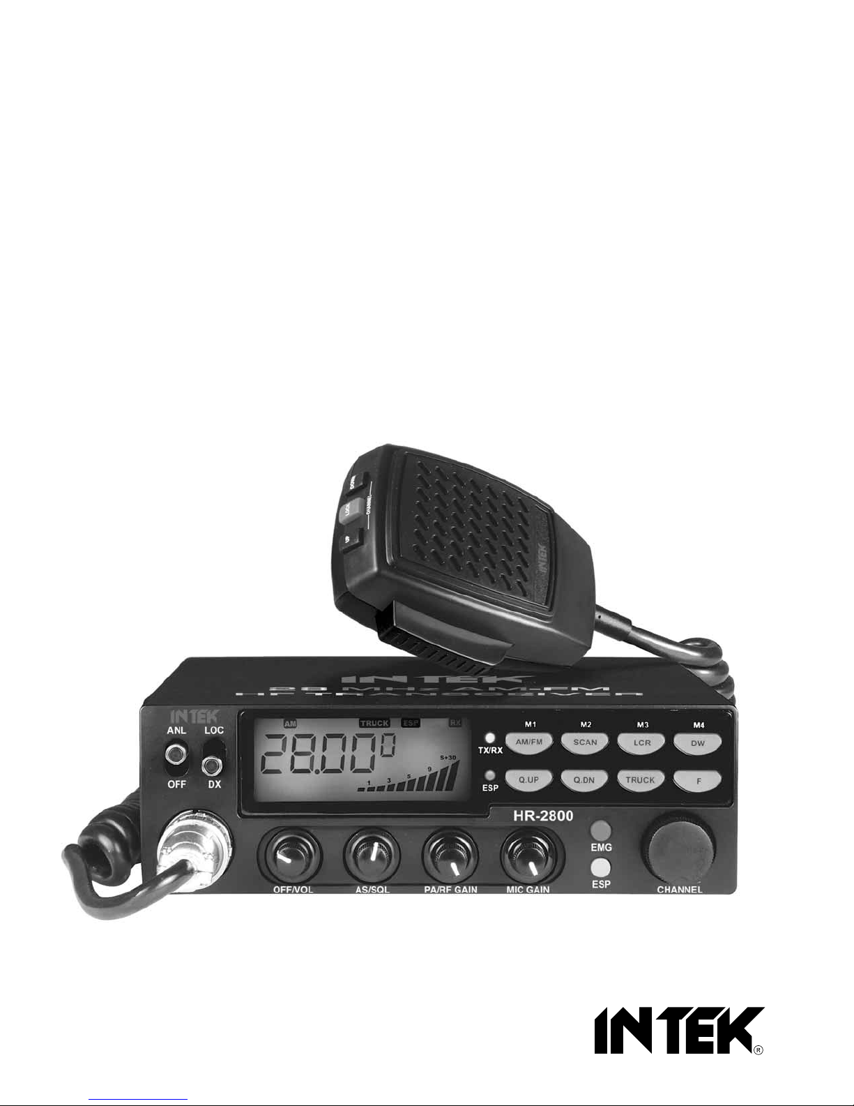
Congratulations!
Congratulations for selecting and purchasing a INTEK quality product. INTEK HR-2800 is a 10-Meter band Amateur
Radio transceiver using advanced hardware and software design. This transceiver includes a number of advanced
functions and systems, therefore it is definitely necessary to carefully read this owner’s manual before using the radio.
With a correct use of the product in accordance with the operating method described in this manual, the product will offer
a trouble free use for many years. INTEK is constantly engaged to develop and provide quality products meeting the
customers requirements, however any suggestion or comments on this product that might help us to improve quality are
warmly welcome.
Content of the packaging
Please check that all the following items are contained in the packaging :
Main unit (transceiver)
DC power cord with fuse holder and fuse
Dynamic microphone
Car mounting bracket
Car mounting bracket accessories (hardware, knobs, etc.)
Microphone bracket
Owner’s manual
English
Controls and operation
- 2 -
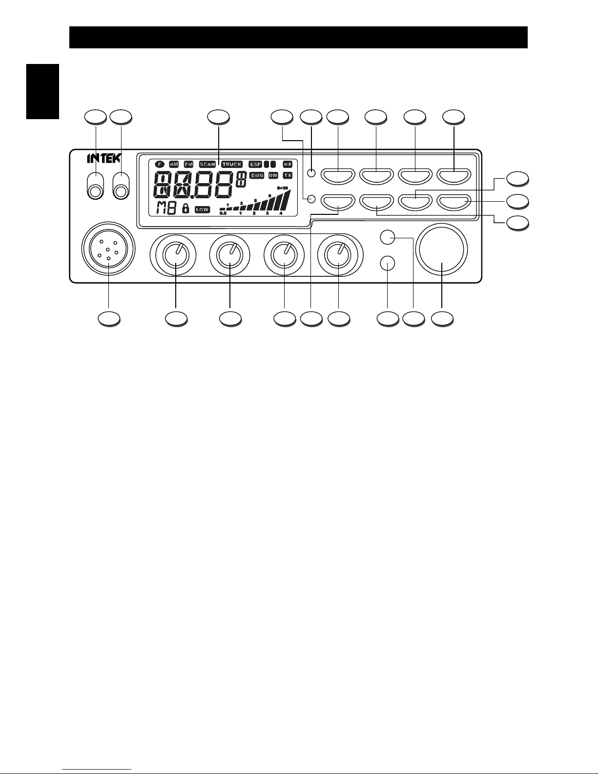
Front panel
1. ANL-OFF Selector
This selector enables the ANL function (Automatic Noise Limited). The ANL reduces electric and electromagnetic noise
on the operating frequency. Move the selector to ANL to enable the Automatic Noise Limiter and move it to OFF to
disable it.
2. LOC-DX Selector
This selector enables the LOC function (Local), in order to attenuate the strength of the incoming signals. The attenuator
is useful in case of very strong incoming signals from local stations that, due to the high signal level, might cause
distortion and poor quality of the received signals. Move the selector to the DX (Long Distance) when receiving weak
signals or from long distance. Move the selector to LOC (Local) when receiving strong signals from local stations.
3. LCD Display
Large size (visible area mm 54 x 21) LCD display with orange colour backlighting system, for best readability. The LCD
display shows all the enabled functions as well as several other information and user programmable functions, like the
full 5-digit frequency readout. LCD also includes a digital 10-bar S/RF Meter to monitor the strength/power of the
received and transmitted signals.
AM/FM SCAN LCR
Q.UP Q.DN TRUCK
DW
F
M1
TX/RX
ESP
ANL LOC
EMG
ESP
CHANNELMIC GAINPA/RF GAINAS/SQLOFF/VOL
HR-2800
OFF DX
M2 M3 M4
1 2 3 54 6 7 8 9
13
11
161718192021 15 14
12
10
C E
English
Controls and operation
- 3 -
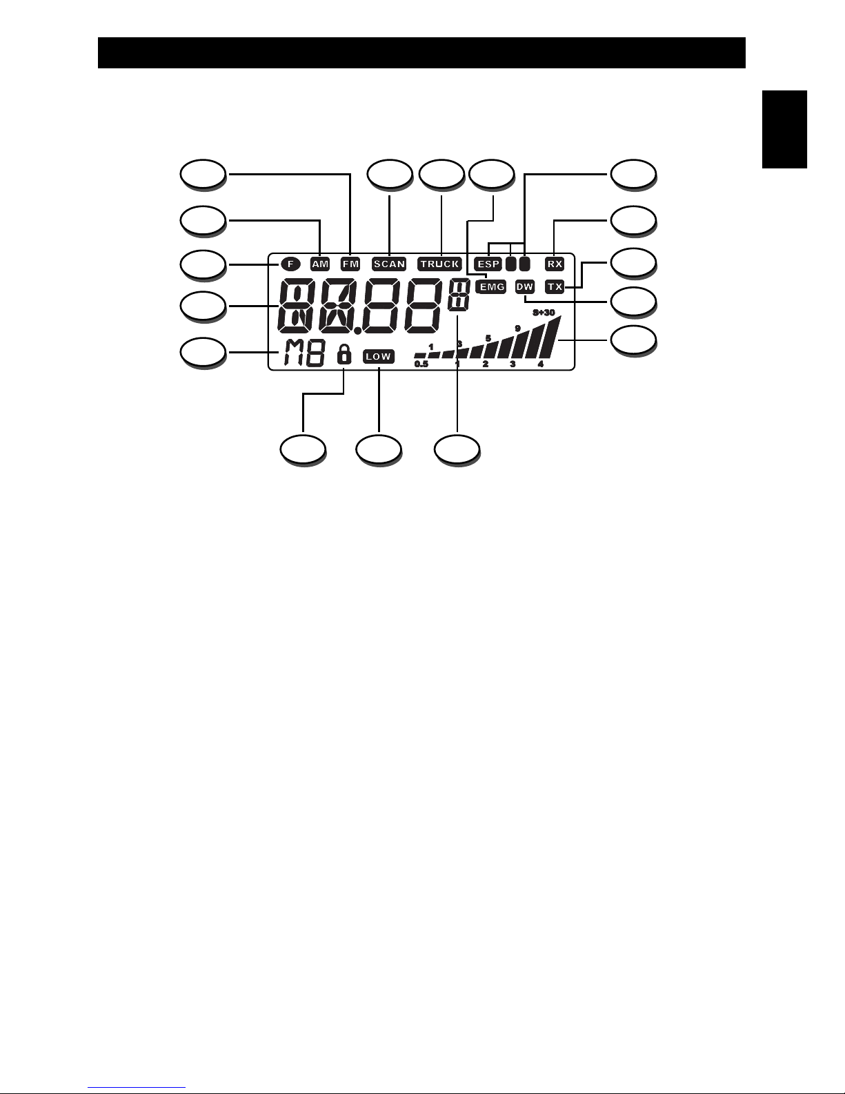
LCD Display
A. AM Icon
The AM icon is lighted when radio receives and transmits in AM mode (amplitude modulation).
B. FM Icon
The FM icon is lighted when radio receives and transmits in FM mode (frequency modulation).
C. SCAN Icon
The SCAN icon is lighted when the SCAN function (automatic search of busy frequencies) is enabled.
D. TRUCK Icon
The TRUCK icon is lighted when the special programmable TRUCK memory frequency (for truck drivers) has been
selected.
E. EMG Icon
The EMG icon is lighted when one of the special quick access frequencies has been selected.
F. ESP C E Icon
The ESP C E icon is lighted when one of the ESP (Electronic Speech Processor) functions has been enabled. The ESP
is an RX & TX electronic modulation processor.
G. RX Icon
The RX icon is lighted when radio is in receive mode.
H. TX Icon
The TX icon is lighted when radio is in transmit mode.
I. DW Icon
The DW icon is lighted when the DUAL WATCH function (automatic monitoring of two frequencies) is enabled.
R
P
Q
A
B C
G
H
L
I
F
NO M
D E
C E
English

Controls and operation
- 4 -
L. S/RF Digital Meter
A digital 10-bar S/RF METER indicates the strength of the received signal (from S0 to S9+30) in the receive mode and
the transmitter RF output power (0 to 20W) in the transmit mode.
M. Alphanumeric Digit
This alphanumeric digit indicates the fifth and last figure (in KHz) of the operating frequency.
N. LOW Icon
The LOW icon is lighted when the transmitter is in the LOW POWER (1W) mode.
O. LOCK Icon
The LOCK icon is lighted when the LOCK function has been enabled.
P. M1-M4 Icons
The M1-M4 icon is lighted when one of the four user programmable memory frequencies has been selected.
Q. Alphanumeric Digit
These four numeric or alphanumeric digits indicate the first four figures of the operating frequency (in KHz).
R. F Icon
The F icon is lighted when the F (Function) mode is enabled, which allows the use of the dual function keys (keys 6, 7,
8, 9, 10, 14).
4. ESP Indicator
This LED indicator lights up in red colour when the ESP (Electronic Speech Processor) function is enabled. The ESP is an
RX & TX electronic modulation processor.
5. TX/RX Indicator
This green-red dual colour LED indicator lights up in green colour when radio is in receive mode and in red colour
when radio is in transmit mode.
6. AM/FM and M1 Key
This key selects the AM or FM operating mode in both RX and TX modes. This key is also used to program and select
the memory frequency M1 (refer to item .11).
7. SCAN and M2 Key
By pressing the SCAN key, the SCAN (automatic scanning of busy frequencies) function is enabled. To enable the SCAN
function, first turn the SQUELCH control (19) clockwise, until the background noise is cut. Then press the SCAN key, radio will
automatically start scanning all frequencies continuously and the SCAN icon (C) will appear on the LCD. Auto-scan stops if a
signal is detected, in order to let the user listen to the incoming signal, auto-scan will start again when no signal is detected on
that frequency. If the PTT Key (27) is pressed within 5 seconds, radio will remain on that frequency, otherwise scanning will start
again. Auto-scan may be also re-started at any time by pressing again the SCAN key (7). To exit the SCAN mode, shortly press
the PTT button (27). This key is also used to program and select the memory frequency M2 (refer to item .11).
English

Controls and operation
- 5 -
8. LCR and M3 Key
By pressing the LCR (Last Channel Recall) key, radio will automatically select the last used frequency. This key is
also used to program and select the memory frequency M3 (refer to item .11).
9. DW and M4 Key
The DW (Dual Watch) function allows automatic alternate monitoring of two programmable frequencies. Set the first
frequency to be monitored using the CHANNEL selector (13) or the frequency selection keys on the microphone (28,
30). To enable the DW function, press the DW key for about 2 seconds, until the DW icon (I) appears and blinks on
the LCD display. Now set the second frequency to monitor using the CHANNEL selector (13) or the frequency
selection keys on the microphone (28, 30). Press again the DW key for about 2 seconds. The DW function is now
enabled and the LCD display will alternately show the two programmed frequencies. The DW icon (I) will be lighted
on the LCD display. Monitoring stops if a signal is detected on one of the two frequencies, in order to let the user
listen to the incoming signal and will start again when no signal is detected on that frequency. It is possible to transmit
on that frequency, by simply pressing the PTT key (27). If there is no transmission within 5 seconds, monitoring will
re-start. To exit the DW mode, shortly press the PTT button (27). This key is also used to program and select the
memory frequency M4 (refer to item .11).
10. TRUCK / ROGER BEEP Key
The TRUCK key is an exclusive memory function. This key allows quick access to a special programmed memory
frequency (i.e. an emergency frequency, a favorite frequency, etc.). To program the TRUCK memory frequency, set
the desired frequency using the CHANNEL selector (13) or the frequency selection keys on the microphone (28, 30).
Then press and hold the TRUCK key until the TRUCK icon (D) appears on the LCD display. The TRUCK frequency is
now stored in the special TRUCK memory and it can be immediately re-called by simply pressing the TRUCK key
(10). This key is also used to enable the Roger Beep function (refer to item .11).
11. F (Function) Key
The F (Function) key is used to enable various functions.
MEMORY FREQUENCIES (M1-M4) PROGRAMMING
Set the frequency to be programmed and stored in one of the four available memories (M1-M4), using the CHANNEL
selector (13) or the frequency selection keys on the microphone (28, 30). Shortly press the F key and the F icon (C)
will blink on the LCD display. Now press and hold one of the memory keys M1, M2, M3 or M4 for about 2 seconds,
until the memory frequency number will appear on the LCD display (i.e. M1). All the specifications associated to each
frequency will be stored in memory (i.e. AM/FM mode, transmitter power, etc.).
MEMORY FREQUENCIES (M1-M4) SELECTION
Shortly press the F key and the F icon (R) will blink on the LCD display. Now press one of the dual function keys (M1
to M4) to quickly recall and access to one of the programmed memory frequencies. The selected memory frequency
number will appear on the LCD display (P).
ROGER BEEP FUNCTION
To enable or disable the RB (Roger Beep Tone), shortly press the F key (11) and the F icon (R) on the LCD will blink.
Now press the TRUCK key (10). The Rb.on icon (RB enabled) or the Rb.oFF icon (RB disabled) will be showed on
the LCD.
English
Controls and operation
- 6 -
12. Q.DN (Quick Down) Key
This key allows fast selection of the operating frequency downward. Each time this key is pressed, the frequency
number moves down by 100 KHz steps.
13. CHANNEL (FREQUENCY) Selector
This knob selects the desired frequency, by 5 KHz steps (frequency increments). The knob may be turned clockwise
to upward frequency selection or counter clockwise to downward frequency selection.
14. EMG Key
Press to quick access to one of the two pre-programmed special frequencies (28.500 MHz or 29.000 MHz). Each
time this key is pressed, radio will select the frequency of 28.500 MHz, then 29.000 MHz, then again the normal
operating frequency.
When one of the special frequency is selected, the EMG icon (E) will appear on the LCD display.
15. ESP (Electronic Speech Processor) Key
The ESP (Electronic Speech Processor) is a unique feature available in some INTEK two-way radios. ESP means
Electronic Speech Processor, in other words electronic modulation processor. This audio processor is microprocessor
controlled and it is also called COMPANDER (Compressor-Expander). It works as a modulation compressor in
transmit mode and as a modulation expander in receive m ode. The ESP allows to obtain a stronger, clear and clean
audio signal and it is a great help in noisy areas and in case of weak signals or in long distance communication. The
efficiency of ESP is even greater when both stations use this device. The 2nd generation ESP allows to enable only
the TX compressor, only the RX expander or both systems.
To enable or disable the ESP functions, press the ESP key (4), as follows :
1) Press the key once to enable the TX modulation compressor. The ESP C (F) icon will appear on the LCD.
2) Press the key again to enable the RX modulation expander. The ESP E (F) icon will appear on the LCD.
3) Press the key again to enable both the TX modulation compressor and the RX modulation expander.
The ESP C E (F) icon will appear on the LCD.
4) Press the key once again to disable all systems.
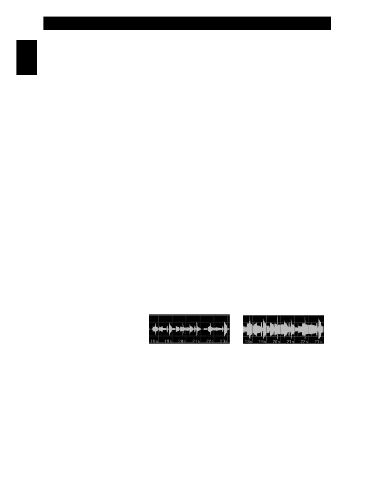
Modulation without ESP Modulation with ESP
100%
0%
100%
ESP performance
of the modulation
in RX and TX modes
English

Controls and operation
- 7 -
16. MIC GAIN Control
This transceiver uses a high quality dynamic microphone. The microphone gain is adjustable with the MIC GAIN control.
By turning the knob clockwise, the microphone gain is increased.
17. Q.UP (Quick UP) Key
This key allows fast selection of the operating frequency upward. Each time this key is pressed, the frequency number
moves up by 100 KHz steps.
18. PA/RF GAIN Control
RF GAIN CONTROL
This transceiver uses a high sensitivity and selectivity receiver circuit. The receiver gain is adjustable with the RF GAIN
control. By turning the knob clockwise, the receiver gain is increased. It is convenient to reduce the receiver gain in case
of very strong signals from local stations and to increase it in case of weak signals or long distance communications.
PA CONTROL
The radio includes the PA (Public Address) function, in order to spread audio messages through an external speaker. To
use the PA function, connect an external speaker (optional) to the PA jack (24) located on the rear side of the radio. Turn
the PA/SQL knob completely counter clockwise to the PA position. The PA icon (Q) appears on the LCD display. Now it is
possible to press the PTT key (27) and speak into the microphone to spread your message through the external
speaker. Adjust the microphone gain with the MIC GAIN knob (16) to the desired level.
19. AS/SQL Control
SQUELCH CONTROL (SQUELCH manual adjustment)
The SQUELCH control allows to silent the receiver by cutting the background noise, when no signals are received. Turn
the knob clockwise until the background noise is cut. Turn the knob counter clockwise (SQUELCH opening) in order to
listen to the weakest signals.
AS CONTROL (SQUELCH fixed setting)
The AS function allows to automatically silent the receiver, avoding the SQUELCH manual adjustment. A fixed
SQUELCH threshold is factory pre-set. To enable the fixed SQUELCH function, turn the knob fully counter clockwise to
the AS position, until a click noise is heard.
20. OFF/VOL (OFF / Volume) Control
This knob switches the radio ON and OFF and it adjusts the volume control. If no signals are being received on the
operating frequency, it is suggested to open the SQUELCH and adjust the volume to the desired level while listening to
the background noise.
21. MICROPHONE Connector
Connect the supplied dynamic microphone to this connector, locking it through the ring nut.
English
Controls and operation
- 8 -
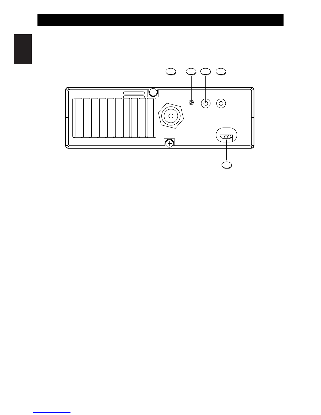
Rear Panel
22. ANTENNA Connector
Antenna connector. Refer to the section INSTALLATION OF THE ANTENNA.
23. S-METER Jack
This jack is for connecting an external S-METER (optional).
24. PA Jack
If the PA function has to be used, connect to the external speaker (optional) to this jack. Refer to item no. 19.
25. EXT (External Speaker) Jack
This jack is for connecting an external speaker (optional).
26. 13.2VDC / 28.0VDC POWER CORD
13.2VDC / 28.0VDC power cord input.
ANTENNA
EXTPAS-METER
POWER
12.0VDC ÷ 28.0VDC
22 23 24 25
26
English
Controls and operation
- 9 -
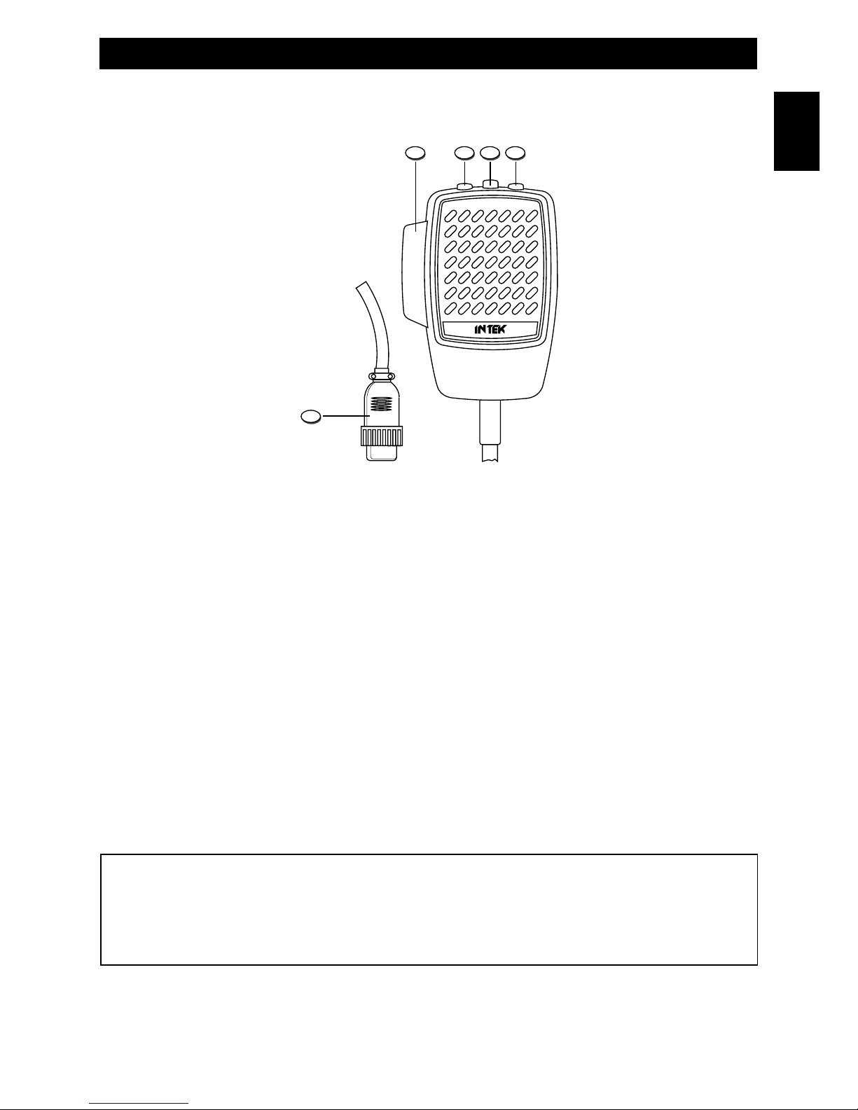
Microphone
27. PTT (Push-to-Talk) Key
Transmitter key. Press the PTT key to transmit and release it to return to the receive mode.
28. UP (Frequency Selector) Key
Each time this key is pressed, the frequency moves 5 KHz upward.
29. LOCK (Keypad Lock) Key
The LOCK function is enabled when pressing this key, in order lock the keypad and prevent entering unwanted
commands. When the LOCK function is enabled, the LOCK icon (O) appears on the LCD display.
30. DOWN (Frequency Selector) Key
Each time this key is pressed, the frequency moves 5 KHz downward.
31. MICROPHONE Plug
Connect the 6-pole microphone plug with locking ring nut to the microphone connector (21) located on the front side of
the radio.
IMPORTANT !
Do never attempt to open the cabinet of the transceiver. No user serviceable parts inside. Internal modifications or
tampering may cause damage to the product, modify its technical specifications and will void warranty rights. If
service or repair are required, please go to an authorised service centre or specialized technician.
292827
31
30
English
 Loading...