

Intek H-510 PLUS, H-512 PLUS Owner's Manual
H-510 PLUS
H-512 PLUS
MULTISTANDARD PROGRAMMABLE
27MHz CB HANDHELD TRANSCEIVERS
OWNER'S MANUAL
MANUALE DI ISTRUZIONI
Downloaded from www.cbradio.nl

Index - Introduction - Content of the Package
Index - Introduction - Content of the package . . . . . . . . . . . . . . . . . . . . . . . . . . . . . . . . . . . . . . . . . . . . . . . . 1
Controls, indicators and operation . . . . . . . . . . . . . . . . . . . . . . . . . . . . . . . . . . . . . . . . . . . . . . . . . . . . . . . 2 - 5
Battery operation . . . . . . . . . . . . . . . . . . . . . . . . . . . . . . . . . . . . . . . . . . . . . . . . . . . . . . . . . . . . . . . . . . . . . . . . 6
Car adaptor operation . . . . . . . . . . . . . . . . . . . . . . . . . . . . . . . . . . . . . . . . . . . . . . . . . . . . . . . . . . . . . . . . . . . . 7
Frequency bands table H-510 PLUS . . . . . . . . . . . . . . . . . . . . . . . . . . . . . . . . . . . . . . . . . . . . . . . . . . . . . . . . 8
Frequency bands table H-512 PLUS - User Information . . . . . . . . . . . . . . . . . . . . . . . . . . . . . . . . . . . . . . . . 9
Frequency band selection / programming . . . . . . . . . . . . . . . . . . . . . . . . . . . . . . . . . . . . . . . . . . . . . . . . . . 10
Table of restrictions on the use of CB transceivers . . . . . . . . . . . . . . . . . . . . . . . . . . . . . . . . . . . . . . . . . . . 10
Specifications - Optional Accessories . . . . . . . . . . . . . . . . . . . . . . . . . . . . . . . . . . . . . . . . . . . . . . . . . . . . . . 11
Table of restrictions on the use of CB transceivers . . . . . . . . . . . . . . . . . . . . . . . . . . . . . . . . . . . . . . . . . . . . I
PCB - Main Board . . . . . . . . . . . . . . . . . . . . . . . . . . . . . . . . . . . . . . . . . . . . . . . . . . . . . . . . . . . . . . . . . . . . II - III
Diagram . . . . . . . . . . . . . . . . . . . . . . . . . . . . . . . . . . . . . . . . . . . . . . . . . . . . . . . . . . . . . . . . . . . . . . . . . . . .IV - V
Block Diagram . . . . . . . . . . . . . . . . . . . . . . . . . . . . . . . . . . . . . . . . . . . . . . . . . . . . . . . . . . . . . . . . . . . . . . VI-VII
Declaration of Conformity H-510 PLUS . . . . . . . . . . . . . . . . . . . . . . . . . . . . . . . . . . . . . . . . . . . . . . . . . . . . VIII
Declaration of Conformity H-512 PLUS . . . . . . . . . . . . . . . . . . . . . . . . . . . . . . . . . . . . . . . . . . . . . . . . . . . . . IX
NOTICE !
Before using this transceiver, please check that the radio has been programmed on the frequency band,
specifications and operating modes allowed by the regulations valid in the country where the product is used. If
not, please proceed to modify the frequency band programming, as it is described in this owner’s manual. This
transceiver is factory pre-programmed on the CE European frequency band CEPT 40CH FM 4W (H-512 PLUS) or on
the E1 band 40CH AM 4W (H-510 PLUS).
It is recommended to carefully read this owner’s manual before using the product. This will also help the user to
prevent using the radio in violation of the regulations valid in the country where the product is used, as well as to
avoid any possible interferences with other services.
Congratulations!
Congratulations for selecting and purchasing an INTEK quality product. This transceiver includes a number of advanced
functions and systems, therefore it is definitely necessary to carefully read this owner’s manual before using the radio.
With a correct use of the product in accordance with the operating method described in this manual, the product will offer
a trouble free use for many years. INTEK is constantly engaged to develop and provide quality products meeting the
customers requirements, however any suggestion or comments on this product that might help us to improve quality are
warmly welcome. This transceiver has advanced hardware and software design, it includes a special multi-standard
programmable circuit, which allows to program the specifications of the radio (frequency bands, operating modes,
transmitter power) in compliance with the regulations valid in the various European countries. Therefore this product
can be used in any country of the European Community. Using this two-way radio is quite easy and only a few minutes
are required to get familiar with it. The operating method and design are the results of years of experience in the
development and production of RF communication equipment, for personal an professional use. However it is strongly
recommended to carefully read this manual in order to get the maximum performances from your transceiver.
Content of the Package
Please carefully check that all the following items are contained in the packaging :
Transceiver Carrying strap
Rubber antenna User manual
Belt clip with mounting hardware
- 1 -
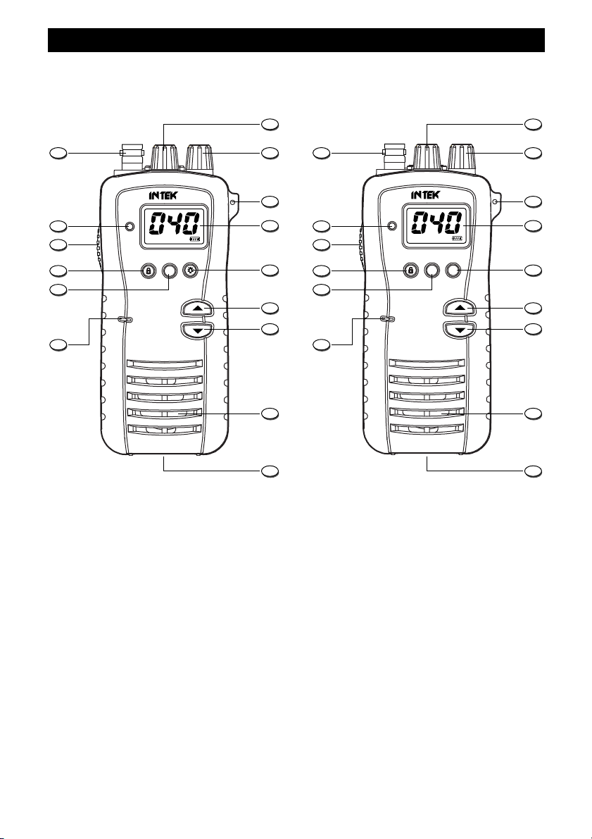
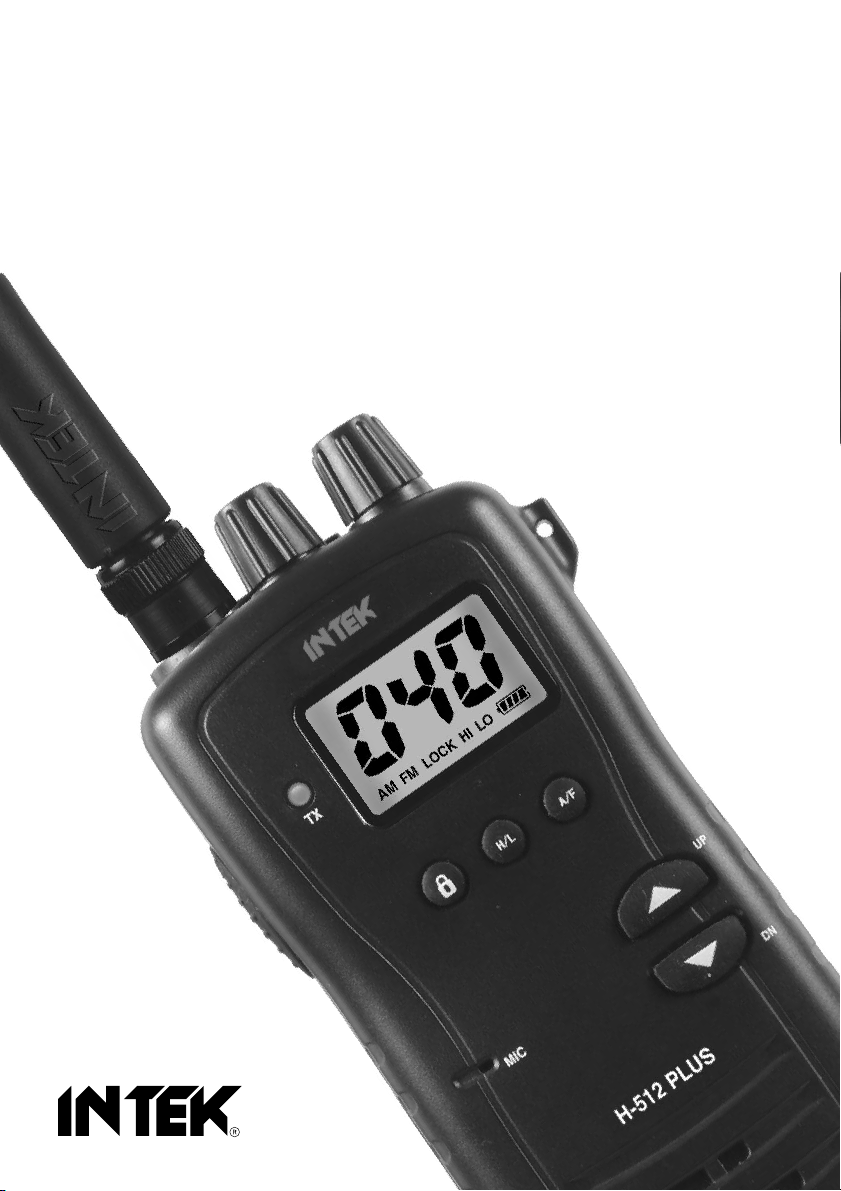
Front Panel
AM/FM CB TRANSCEIVER
MIC
H-512 PLUS
TX
UP
DN
H/L A/F
AM FM HI LOLOCK
1 3
5
6
7
8
9
10
4
2
11
MIC
TX
UP
DN
H/L
AM FM HI LOLOCK
14
15
13
12
1 3
5
6
7
8
9
10
4
2
11
15
13
12
AM CB TRANSCEIVER
H-510 PLUS
14
Controls, Indicators and Operation
1. Antenna Connector
Connect the supplied rubber antenna to this BNC connector, insert and gently turn it clockwise until blocked.
Do not overtighten. If the antenna is not or not correctly connected, damage may be caused to the radio.
2. SQ/SQL Control
SQL CONTROL (SQUELCH manual adjustment)
The SQL control allows to silent the receiver by cutting the background noise, when no signals are received. Turn the
knob clockwise until the background noise is cut. Turn the knob counter clockwise (SQUELCH opening) in order to listen
to the weakest signals.
SQ CONTROL (SQUELCH fixed setting)
The SQ function allows to automatically silent the receiver, avoding the SQUELCH manual adjustment. A fixed
H-510 PLUS H-512 PLUS
SQUELCH threshold is factory pre-set. To enable the fixed SQUELCH function, turn the knob fully counter clockwise to
the SQ position, until a click noise is heard.
- 2 -
Controls, Indicators and Operation
AM FM HI LOLOCK
E D
G
A
F
B
C
3. VOL (OFF/Volume) Control
This knob switches the radio ON and OFF and it adjusts the volume control. If no signals are being received on the
operating channel, it is suggested to open the SQUELCH and adjust the volume to the desired level while listening to the
background noise.
4. Handstrap Hole
Hole to insert and attach the supplied carrying handstrap.
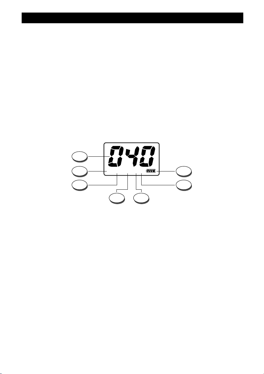
5. LCD Display
Large size LCD display with green color backlight function for best readability in darkness. It indicates
simultaneously all the programmed settings and all the enabled functions, such as the operating channel
number, the operating mode and 4-bar battery level indicator.
LCD Display
A. Channel Number
It indicates the operating channel number or the frequency band ID code.
B. Battery Level Indicator
It shows the current battery level condition.
C. LO Icon
The LO Icon (C) is lighted when the transmitter is in LOW POWER mode (1W).
D. Icona HI
The HI Icon (D) is lighted when the transmitter is in HIGH POWER mode (4W).
E. LOCK Icon
The LOCK icon (E) is lighted when the keypad lock function has been enabled.
F. FM Icon (H-512 PLUS)
The FM icon (F) is lighted when radio has been set to the FM (Frequency Modulation) operating mode.
G. AM Icon
The AM icon is lighted when radio has been set to the AM (Amplitude Modulation) operating mode.
- 3 -
 Loading...