


GP620B
INTEDGE INDUSTRIES.INC.
1875 CHUMLEY ROAD
GP Series MIXERS
1-26 At EXIT 38
P.O. BOX 969
WOODRUFF, S.C. 29388
Tel. (864) 969-9601
Fax (864) 969-9604
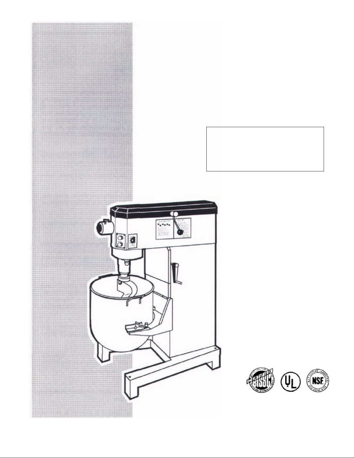
MODELS 620 & 630
Bench & Floor

- TABLE OF CONTENTS -
SECTION 1
DESCRIPTION
SECTION 2
INSTALLATION
SECTION 3
OPERATION
SECTION 4
MAINTENANCE & TROUBLESHOOTING 21
SECTION 5
ATTACHMENTS & ACCESSORIES
SECTION 6
PARTS LIST
SECTION 7
ELECTRICAL SCHEMATICS
A Manual Usage 1
B Mixer Usage 1
C Mixer Models 1
D Specifications 2
E Detail and Dimension Drawings 3-4
F Component Function 5
I Unpacking 7
II Installation 7
III Pre-Operation Checks 8
I Mixer Set-Up 9-11
II Mixer Operation 12
A Before Starting Mixer 12
B Timer 12
C Speed Selector 13
D Overload 13
E Bowl Accessories 14
F Attachment Hub 15
III Agitator Uses 16
IV Operation 18
V Cleaning & Helpful Hints 19
VI Absorption Ratio 19
VII Production Capacity Chart 20
I Lubrication 21
II Cleaning 21
III Troubleshooting 21
Attachments 23
Accessories 24
Overall Exploded View and Parts List 26-27
Transmission Exploded View 28-29
Electrical Components 30
100V/240V, 1 Ph 32
208V/240V, 3 Ph 32
440V/480V 3 Ph 33
380V,3Ph, Scandinavian Only 33
CONTENTS PAGE
section 1
description
A. Manual Usage
This Owners Manual is to be used with the
GP Series Model 620 and Model 630
Mixers which are manufactured by
Middleby Marshall Inc.
B. Mixer Usage
Model 620 and 630 Mixing Machines are
intended for use in bakeries and kitchens.
The mixers are used to mix:
• Bread Dough
• Roll Dough
• Pizza Dough
• Cake Batter
• Cookie Dough
• Pastry Dough
The mixers are also used for lighter mixing
and whipping such as:
• Whipped Potatoes
• Egg Whites and Whole Eggs
• Whipped Cream
The mixing machines can be equipped with
optional accessories for preparing meats,
vegetables and cheeses.
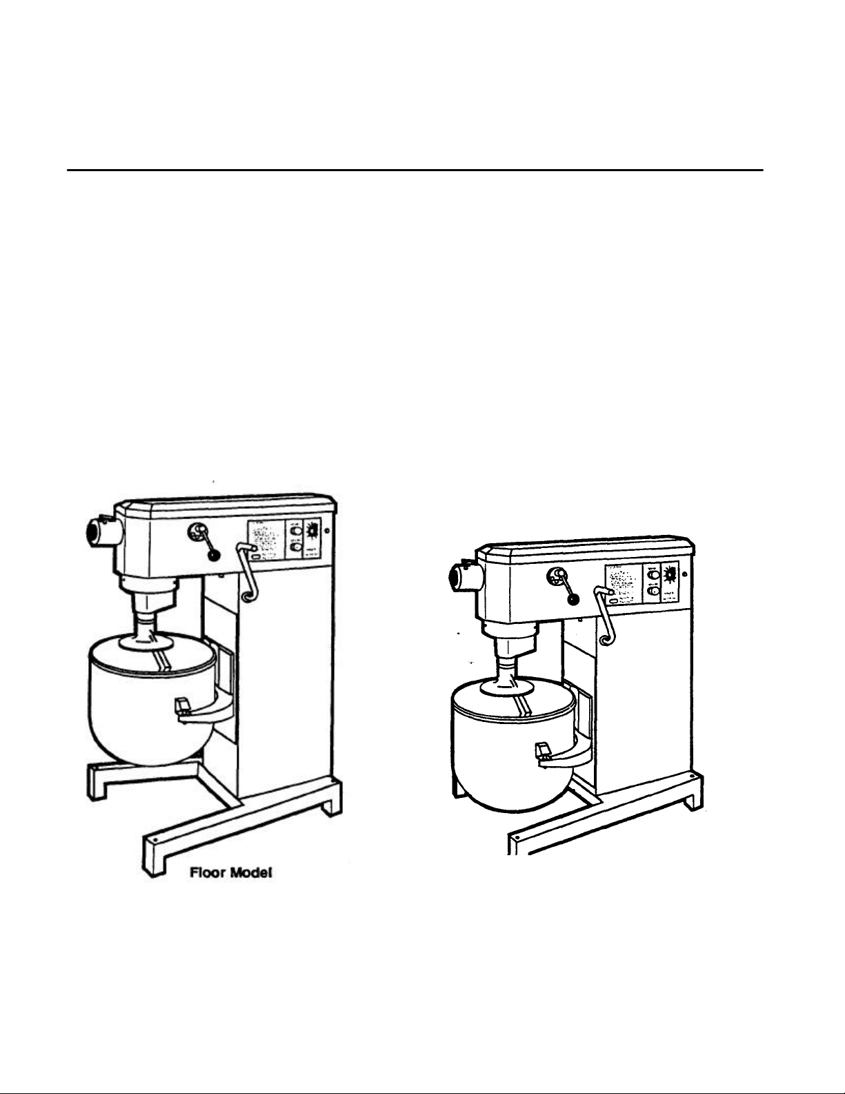
C. Mixer Models
GP Series Model 620 and Model 630 Mixers
are both available in either Floor Models or
Bench Models. The mixers are also available
as domestic or export units.
Figure 1-1
1

section 1
description
D. Specifications
12qt. 20 qt. 20qt. 30 qt.
620
Capacity 12qt.(11.25ltr.) 20qt.(19ltr.) 20qt.(19ltr.) 30 qt. (28 hr.)
Horsepower 1/2 H.P. 1/2 H.P. 3/4 H.P. 3/4 H.P.
Transmission Three Speed Gear with Neutral between each speed setting.
Agitator Speeds:
1st (low) 89 rpm 89 rpm 89 rpm 89 rpm
2nd (medium) 161 rpm 161 rpm 161 rpm 161 rpm
3rd (high) 310 rpm 310 rpm 310 rpm 310 rpm
Accessory Drive Speeds
1st (tow) 178 rpm 178 rpm 178 rpm 178 rpm
2nd (medium) 322 rpm 322 rpm 322 rpm 322 rpm
3rd (high) 620 rpm 620 rpm 620 rpm 620 rpm
Floor Model:
Model
Model
630
Machine Dimensions
Refer to Detail Drawings on next page
Machine Only Weight 255 IDS. (111 kg) 255lbs.(111kg) 265 lbs.016kg) 265 lbs.(116kg)
Shipping Weight - Domestic 294 lbs.(135kg) 294lbs.(135kg) 305 lbs.(159kg) 305 lbs.(159kg.)
Shipping Cube - Domestic 31.7 ft
3
(0.9m
) 31.7 ft
3
3
(0.9m
) 31.7ft
3
3
(0.9m
) 31.7ft
3
(0.9m
3
)
3
Shipping Weight - Export 294 lbs.(135kg) 294 lbs.(135kg) 305 lbs.(159kg) 305 lbs.(159kg.)
Shipping Cube - Export 31.7 ft
3
(0.9m
) 31.7 ff (0.9m3) 31.7 ft
3
3
(0.9m
) 31.7ft
3
(0.9m•
>
)
3
Shipping Carton Dimensions - Domestic 54-3/8"H(1381mm) 54-3/8"H(1381mm) 54-3/8"H(1381mm) 54-3/8"H(1381mm)
and Export x x x x
35-1/4"D(895mm) 35-V4"D(895mm) 35-1/4"D(895mm) 35-1/4"D(895mm)
x x x x
32-7/8-W(835mm) 32-7/8'W(835mm) 32-7/8"W(835mm) 32-7/8-W(835mm)
Bench Model
Machine Dimensions
Refer to Detail Drawings on next page
Machine Only Weight 240 lbs.(93kg) 240 lbs.(93kg.) 250 lbs.(98kg.) 250 lbs.(98kg.)
Shipping Weight - Domestic 280 lbs.( 109kg.) 280 lbs.(109kg.) 290 lbs.(122kg.) 290 lbs.(122kg.)
Shipping Cube - Domestic 25.8ft
3
(0.73m
) 25.8ft
3
(0.73m
3
) 25.8ft
3
(0.73m
3
) 25.8ft
3
(0.73m
3
)
3
Shipping Weight - Export 280Ibs.(109kg.)' 280 lbs.(109kg.) 290 lbs.(122kg.) 290 lbs.(122kg.)
Shipping Cube - Export 25.8ft
3
(0.73m
) 25.3ft
3
(0.73m-
1
) 25.8ft
3
(0.73m
3
) 25.8ft
3
(0.73m
3
)
3
Shipping Carton Dimensions - Domestic 54-3/8"H(1381mm) 54-3/8"H(1381mm) 54-3/8'H(1381mm) 54-3/8"H(1381mm)
and Export x x x x
35-1/4"D(895mm) 35-1/4"D(895mm) 35-1/4"D(895mm) 35-1/4"D(895mm)
x x x x
32-7/8'W(835mm) 32-7/8"W(835mm) 32-7/8"W(835mm) 32-7/8"W(835mm)
Electrical Cord and Plug
for 115V/60Hz/1ph 7 ft. (2.1 m) 7 ft. (2.1 m) 7 ft. (2.1 m) 7 ft. (2.1 m)
3 Wire Cord 3 Wire Cord 3 Wire Cord 3 Wire Cord
Grounding Plug Grounding Plug Grounding Plug Grounding Plug
Timer 15 minutes 15 minutes 15 minutes 15 minutes
section 1
description
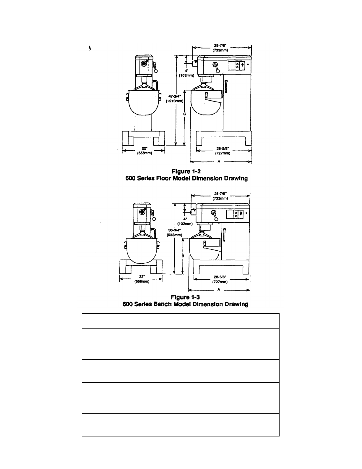
E.. Detail and Dimension Drawlngs
Dimension
Model 620 -
Floor
12 qt.
20 qt.
Bench
12qt.
20 qt.
Modal 630 -
Floor
20 qt.
30 qt.
Bench
20 qt.
30 qt.
A B C
28-3/4" n/a 29"
30-1/4" n/a 30"
28-3/4" 18" n/a
30-1/4" 19" n/a
30-1/4" n/a 29"
30-3/4" n/a 30"
30-1/4" 18" n/a
30-3/4" 19" n/a
(Refer to above drawings)
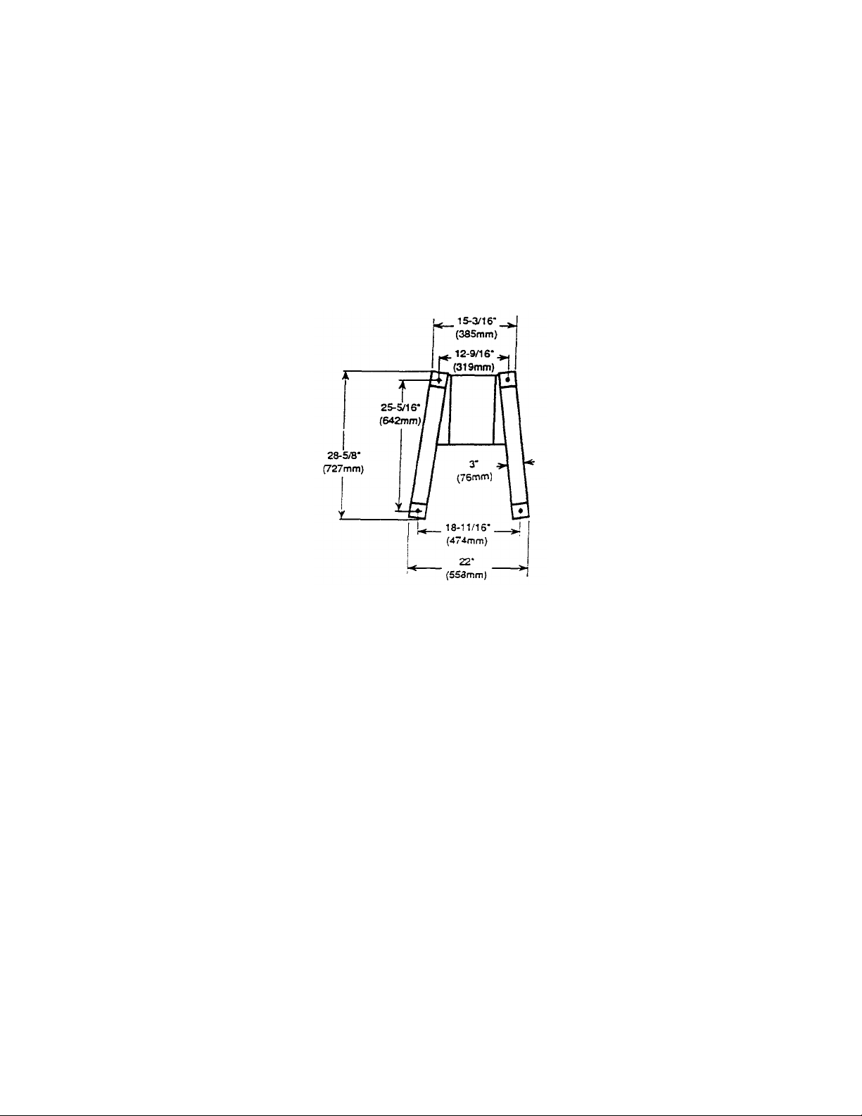
Figure 1-4
Floor Model & Bench Model Base Dimension Drawing
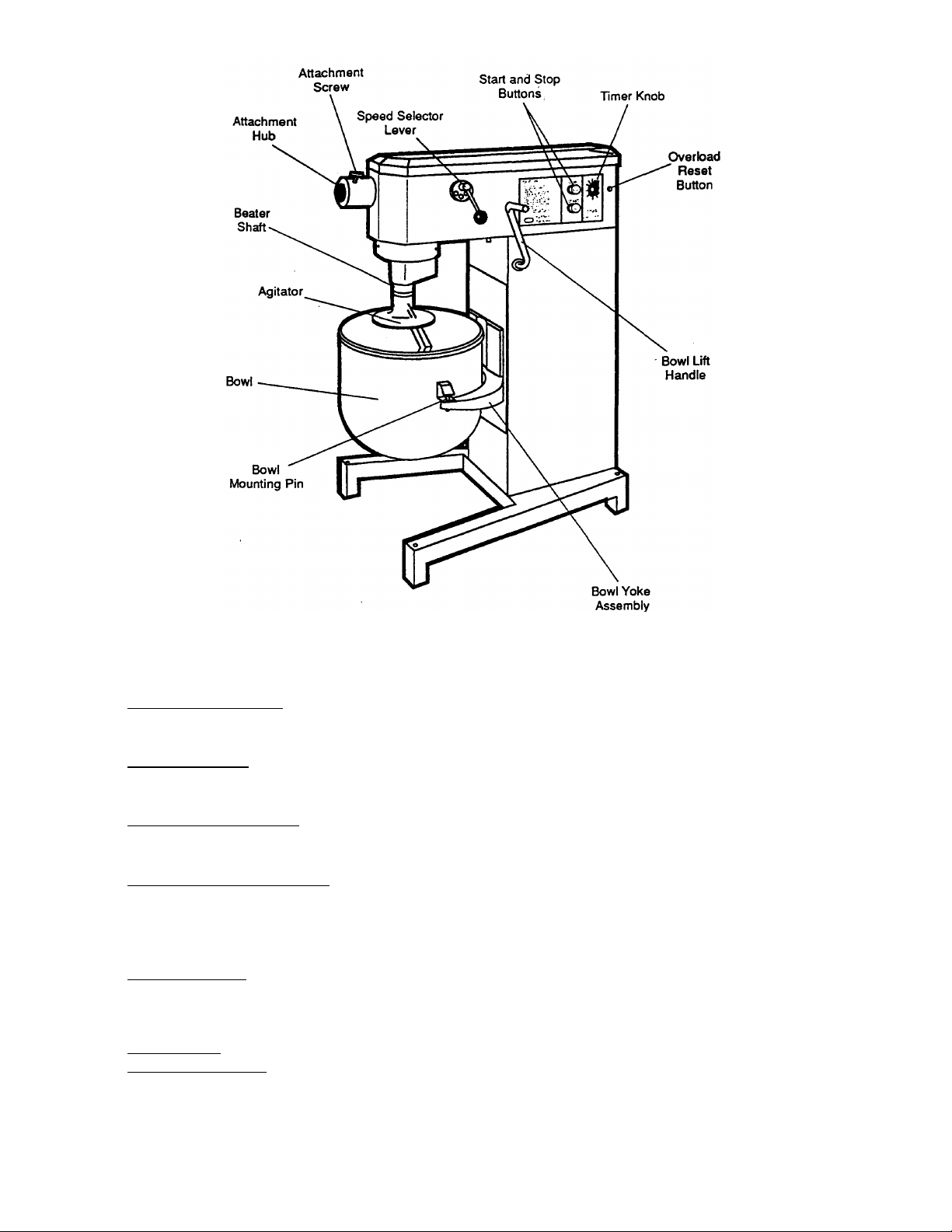
F. Component Function • Refer to Figure 1-5
Bowl Yoke Assembly - The bowl yoke assembly is used to hold the bowl in place. The Model 620
bowl yoke has a pin on each side and two at the rear to hold the bowl in place. The Model 630
bowl yoke has a pin on each side and no rear pins.
Bowl Lift Handle - The bowl lift handle is used to lift the bowl into place by lifting the bowl and yoke
assembly.
When the bowl is lifted into place it is at the correct height for mixing operations.
Speed Selector Lever - The speed selector lever is used to select one of the three speeds of the
transmission.
There is a neutral position between each speed setting.
START and STOP Buttons - The START and STOP Buttons are used to start and instantly stop
the mixer. TimerKnob-The timer knob is used to set the amount of time the mixerwill run and then
shut off automatically. Overload Reset Button -The overload reset button is used to reset the
motor after being stalled by an overload.
Also refer to the Operation Section of this manual.
Attachment Hub - The attachment hub is used for driving a vegetable slicer or chopper/grinder.
Agitator- There are six types of agitators used for various purposes, refer to Operation Section of
this manual
for agitator usage.
Beater Shaft - The beater shaft is used to hold agitators.
Bowl Mounting Pin - There are bowl mounting pins located on both sides of the bowl yoke
assembly. The
mounting brackets on the sides of the bowl are placed on the bowl mounting pins and are used to
support the bowl and keep it in a stationary position.
Figure 1-5
Component Location
section 2
Figure
2-1
installation
I. UNPACKING
A. Your Middleby Marshall GP Series Mixer will
arrive in a carton 54-3/8"H(1381 mm) x 351/4-D (895mm) x 32-7/8"W(835mm). Cut and
remove bands from around the carton.
Remove nails at bottom of carton to expose
the mixer and accessories. Before removing
mixer from the skid check packing list against
your order and inspect all Hems for damage
during transit. If any damage is found save all
packing materials and parts and arrangement
should be made to file a claim against the
carrier.
B. Loosen and remove the 4 lag bolts holding
the mixer onto the skid.
C. To process a valid claim the driver or other
representative of the delivering freight
company should immediately be notified and
requested to witness and certify in writing the
damage found. Interstate Commerce
Regulations require that the claim must be
initiated by the consignee.
D. After the damage has been certfied a
Middleby Marshall, Inc., Authorized
Service and Parts Distributor, should
immediately be contacted for assistance
in the repair or replacement of damaged
parts. Failure to do so could lead to added
costs.
lated room with proper storage facilities for
agitators and accessories.
C. Be sure to allow working space on the
controls side of the mixer.
D. It is recommended that the accessories all
be thoroughly washed and rinsed in very
hot, soapy water. The mixer should be
washed with mild soapy water and then
rinsed clean.
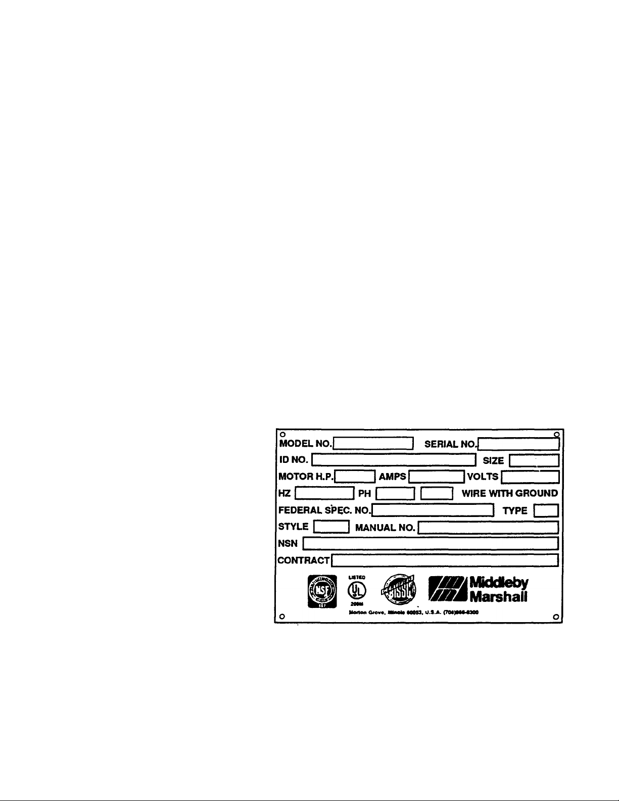
E. Electrical Connections - The Specification
Data Plate shown in Rgure 2-1 and located
on the outside of mixer must be noted for
proper electrical requirements before
connecting the mixer to the electrical
supply.
II. INSTALLATION
A. Bench and floor model mixers are both
designed to be placed on rigid level
surfaces. Since the operating weight of
this machine is approximately 250 tos
(112 kg), the bench or floor mounting
surface must be strong enough to support
this weight. The base of the mixer is
provided with mounting holes(refer to
base dimension drawing on Page 4) for
bolting to a bench, counter or floor, if
necessary.
B. Sanitary standards for food processing areas
require a clean, adequately lighted and venti
Specification Data Plate

section 2
III. PRE
-
OPERATION CHECKS
installation
• Machines with cord:
A 7 ft. (2.1 m) cord and grounding plug comes
standard with all 115V/60Hz/1ph mixers. On
mixers with other voltages local codes govern
type of cord and wiring to the mixer. Consult your
local electrician
• Machines without cord:
IMPORTANT:
All electrical connections must be made by a
certified electrician.
1. Amps - Check amp rating on
mixer Specification Data Plate to
properly size your electrical wiring
and circuit breaker.
2. Voltage (115V, 220V, etc.) and
phase (1 or 3 phase) on mixer
Specification Data Plate must
correspond with voltage and
phase of your power supply.
Figure 2-2 Correct Planetary
Rotation
NOTE: If your machine is equipped with a 15 minute
timer turn the knob clockwise to the "Hold'position. The
mixer motor can then be operated manually for the preopera-tion checks by pushing the start and stop switch.
A. Before attaching any accessories to the mixer
make certain that the direction of rotation of the
planetary corresponds to the arrow located on the
head of the mixer as shown in Figure 2-2. Refer to
Section 3 for operating instructions to oerform the
above check.
3. Type of power supplied (60Hz
or 50Hz) must correspond with
rating on Specification Data Plate.
IMPORTANT:
The mixer must be wired and
grounded in accordance with
local codes, or in the absence of
local codes, with ANSl/NFPA latest edition.
4. This mixer has been completely
internally wired at the factory. To put into operation,
connect the power supply to mixer. This is the only
connection required.
If the planetary is not rotating in the proper
direction you must change wiring. On single
phase motors change wire connection as per
instructions inside motor cover. On three phase
motors reverse any two of the three line leads.
B. It is recommended that each of the mixer bowls,
agitators and accessories be assembled onto
the mixer to become familiar with their installation. Refer to Operation Section 3 of this manual
for bowl, agitator and accessory installation.
C. Operate the machine with an empty mixing bowl
and agitator installed in place to verify that there
is clearance between the rotating agitator and
inside of bowl. The agitator and bowl clearance
has been set at the factory and should be approximately 1/4".
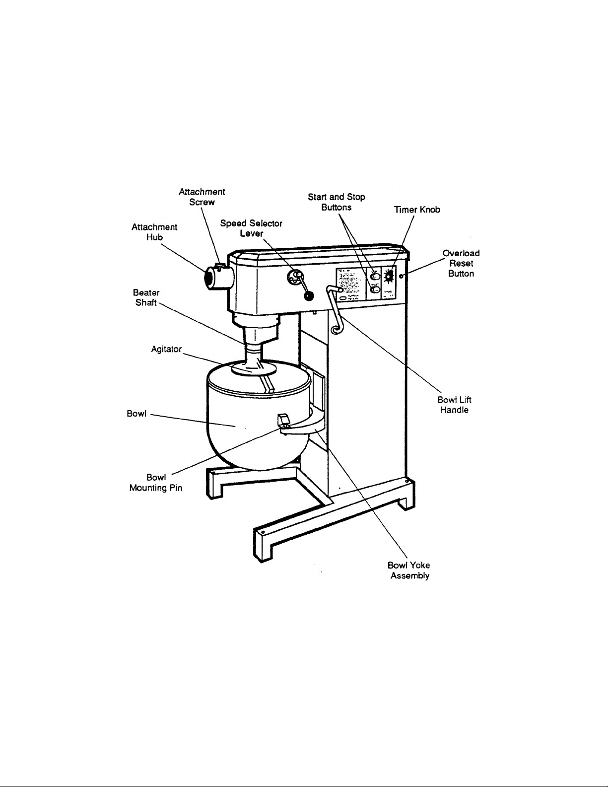
section 3
operation
I. MIXER SET-UP
Figure 3-1
Controls and Components
 Loading...