


 Loading...
ENGLISH
ORTHOPANTOMOGRAPH® OP300
3D Dental X-Ray System
User Manual
210457 rev. 7

ORTHOPANTOMOGRAPH® OP300
Copyright |
Code: 210457 rev 7 Date: July 7, 2014 |
|
|
Copyright © 7/7/14 by Instrumentarium Dental, PaloDEx |
|
|
Group Oy. |
|
|
All rights reserved. |
|
|
ORTHOPANTOMOGRAPH®/ |
INSTRUMENTARIUM |
DENTAL™/ CLINIVIEW™ is a registered trademark/ a common law trademark of Instrumentarium Dental,
PaloDEx Group Oy.
U.S. patents US6731717, US6829326 and USRE41197.
Finnish patents 114383.
Documentation, trademark and the software are copyrighted with all rights reserved. Under the copyright laws the documentation may not be copied, photocopied, reproduced, translated, or reduced to any electronic medium or machine readable form in whole or part, without the prior written permission of Instrumentarium Dental.
The original language of this manual is English.
Instrumentarium Dental reserves the right to make changes in specification and features shown herein, or discontinue the product described at any time without notice or obligation. Contact your Instrumentarium Dental representative for the most current information.
Manufacturer |
Instrumentarium Dental, PaloDEx Group Oy |
|
Nahkelantie 160 (P.O. Box 20) |
|
FI-04300 Tuusula |
|
FINLAND |
|
Tel. +358 10 270 2000 |
|
Fax. +358 10 270 2230 |
|
For service, contact your local distributor. |

ORTHOPANTOMOGRAPH® OP300

Table of Contents
1 Introduction.................................................................................................................. |
1 |
|
1.1 |
ORTHOPANTOMOGRAPH® OP300 .................................................................... |
1 |
1.2 |
References............................................................................................................ |
2 |
1.3 |
Intended use ......................................................................................................... |
2 |
1.4 |
Associated documentation .................................................................................... |
3 |
1.5 |
Abbreviations used in this manual ........................................................................ |
3 |
1.6 |
Warnings and precautions .................................................................................... |
3 |
|
1.6.1 Warnings to be observed during use ......................................................... |
3 |
|
1.6.2 Warnings for cross infection....................................................................... |
5 |
|
1.6.3 General warnings....................................................................................... |
5 |
1.7 |
Disclaimer ............................................................................................................. |
8 |
1.8 |
Disposal ................................................................................................................ |
8 |
2 Unit description ........................................................................................................... |
9 |
|
2.1 |
Main parts and controls......................................................................................... |
9 |
2.2 |
Patient positioning lights ..................................................................................... |
11 |
2.3 |
Patient positioning panel ..................................................................................... |
14 |
|
2.3.1 Cephalometric unit (optional) ................................................................... |
14 |
2.4 |
Emergency stop switch ....................................................................................... |
15 |
3 Imaging programs ..................................................................................................... |
17 |
|
3.1 |
Panoramic programs........................................................................................... |
17 |
3.2 |
Cephalometric programs..................................................................................... |
23 |
3.3 |
3D SFOV programs............................................................................................. |
25 |
3.4 |
3D MFOV (Maxio) programs ............................................................................... |
26 |
3.5 |
Selecting resolution and FOV ............................................................................. |
28 |
3.6 |
MAR, Metal Artifact Reduction ............................................................................ |
29 |
3.7 |
Exposure settings for 3D imaging ....................................................................... |
30 |
4 Touch screen display................................................................................................ |
33 |
|
4.1 |
Main control panel............................................................................................... |
33 |
4.2 |
Modality section .................................................................................................. |
34 |
|
4.2.1 Exposure indicators and settings ............................................................. |
34 |
4.3 |
Automatic dose control (ADC)............................................................................. |
35 |
4.4 |
Status section...................................................................................................... |
36 |
4.5 |
Other sections ..................................................................................................... |
36 |
5 Using the unit............................................................................................................. |
39 |
||
5.1 |
Attaching and removing the sensor..................................................................... |
39 |
|
|
5.1.1 |
Attaching the sensor ................................................................................ |
39 |
|
5.1.2 |
Removing the sensor ............................................................................... |
40 |
5.2 |
Preparing the system .......................................................................................... |
40 |
|
5.3 |
Panoramic exposures ......................................................................................... |
41 |
|
|
5.3.1 |
Positioning devices .................................................................................. |
41 |
|
5.3.2 |
Sectional imaging..................................................................................... |
42 |
|
5.3.3 |
General instructions ................................................................................. |
42 |
|
5.3.4 |
Default exposure settings........................................................................ |
43 |
|
5.3.5 User Configurable Default Program ......................................................... |
44 |
|
rev |
i |

|
|
5.3.6 |
Patient positioning.................................................................................... |
44 |
|
|
|
|
5.3.6.1 |
Panoramic exposure.................................................................. |
44 |
|
|
|
5.3.6.2 |
TMJ exposure............................................................................ |
48 |
|
|
|
5.3.6.3 |
Maxillary Sinus exposure........................................................... |
51 |
|
|
5.3.7 |
Taking the exposure................................................................................. |
53 |
|
|
|
5.3.8 |
Multilayer Selection .................................................................................. |
54 |
|
|
5.4 |
Cephalometric exposures ................................................................................... |
56 |
||
|
|
5.4.1 |
General instructions ................................................................................. |
56 |
|
|
|
5.4.2 |
Patient positioning.................................................................................... |
58 |
|
|
|
|
5.4.2.1 Pediatric lateral and Lateral projection ...................................... |
58 |
|
|
|
|
5.4.2.2 |
PA projection ............................................................................. |
60 |
|
|
|
5.4.2.3 |
Reverse towne projection .......................................................... |
61 |
|
|
|
5.4.2.4 |
Waters view ............................................................................... |
62 |
|
|
|
5.4.2.5 Carpus view (Not available in USA and Canada)...................... |
63 |
|
|
|
|
5.4.2.6 |
Taking the exposure .................................................................. |
63 |
|
5.5 |
3D exposures ...................................................................................................... |
|
64 |
|
|
|
5.5.1 |
Positioning devices .................................................................................. |
64 |
|
|
|
5.5.2 |
General instructions ................................................................................. |
64 |
|
|
|
5.5.3 |
Patient positioning.................................................................................... |
66 |
|
|
|
5.5.4 |
Scout image ............................................................................................. |
70 |
|
|
|
5.5.5 |
3D image.................................................................................................. |
71 |
|
|
|
|
5.5.5.1 Stone model and radiographic guide scan ................................ |
72 |
|
|
5.6 |
Warnings and error messages ............................................................................ |
73 |
||
|
|
5.6.1 |
Acknowledging errors............................................................................... |
73 |
|
|
|
5.6.2 |
Image transfer errors................................................................................ |
73 |
|
6 |
Troubleshooting ........................................................................................................ |
|
75 |
||
|
6.1 |
Patient positioning............................................................................................... |
75 |
||
|
6.2 |
Image appearance .............................................................................................. |
78 |
||
|
6.3 |
Artefacts .............................................................................................................. |
|
79 |
|
|
6.4 |
Unit operation...................................................................................................... |
|
81 |
|
7 |
Maintenance............................................................................................................... |
|
83 |
||
|
7.1 |
Maintenance procedure ..................................................................................... |
83 |
||
|
|
7.1.1 |
Annual maintenance ................................................................................ |
83 |
|
|
|
7.1.2 |
Calibration intervals.................................................................................. |
83 |
|
|
7.2 |
Changing the fuses ............................................................................................. |
84 |
||
|
7.3 |
Cleaning and decontaminating the unit............................................................... |
84 |
||
8 |
Calibration and adjustment ...................................................................................... |
87 |
|||
|
8.1 |
Introduction ......................................................................................................... |
|
87 |
|
|
8.2 |
Preparing for calibration ...................................................................................... |
88 |
||
|
8.3 |
Panoramic calibration.......................................................................................... |
89 |
||
|
|
8.3.1 |
Panoramic geometry calibration............................................................... |
89 |
|
|
|
8.3.2 |
Panoramic pixel calibration ...................................................................... |
90 |
|
|
|
8.3.3 Panoramic Quality Check (optional)......................................................... |
91 |
||
|
8.4 |
3D calibration ...................................................................................................... |
|
93 |
|
|
|
8.4.1 |
3D geometry calibration ........................................................................... |
93 |
|
|
|
8.4.2 |
3D pixel calibration................................................................................... |
93 |
|
|
|
8.4.3 3D Quality Check program....................................................................... |
95 |
||
|
8.5 |
Cephalometric calibration.................................................................................... |
96 |
||
ii |
rev |

|
|
8.5.1 Ceph pixel calibration............................................................................... |
96 |
|
|
8.5.2 Ceph Quality check program (Optional)................................................... |
96 |
9 |
Technical data............................................................................................................ |
99 |
|
|
9.1 |
Technical specifications ...................................................................................... |
99 |
|
9.2 |
Unit dimensions................................................................................................. |
109 |
|
9.3 |
Symbols that appear in the unit......................................................................... |
111 |
|
9.4 |
Labels on the unit.............................................................................................. |
113 |
|
9.5 |
Electromagnetic Compatibility (EMC) tables..................................................... |
114 |
|
9.6 |
X-ray tube assemblies....................................................................................... |
119 |
10 |
PC requirements...................................................................................................... |
121 |
|
|
10.1 |
Minimum PC requirements................................................................................ |
121 |
|
10.2 |
The dental imaging software ............................................................................. |
124 |
rev |
iii |

iv |
rev |

1Introduction
1.1ORTHOPANTOMOGRAPH® OP300
INSTRUMENTARIUM DENTAL™ ORTHOPANTOMOGRAPH® OP300 x-ray unit (hereafter called “OP300”) is a dental x-ray system for producing high quality digital images of dentition, TM-joints and skull. In order to take images with OP300 you need a suitable PC hardware connected to the OP300 unit and CLINIVIEW™ software (or suitable third party software via TWAIN driver) to capture and manage images.
OP300 performs the following procedures:
Panoramic
•Standard panoramic
•Pediatric panoramic
•Wide arch panoramic
•Bitewing
•TMJ, PA projection
•Ortho TMJ, axial corrected lateral projection
•Maxillary sinus
•Ortho Zone enhanced panoramic
•Orthogonal panoramic
Cephalometric (optional)
•Cephalometric lateral projection
•Cephalometric pediatric lateral projection
•Cephalometric postero-anterior (PA) projection
•Reverse Towne projection
•Waters view
•Carpus program (optional) (Not available in USA and Canada)
210457 rev 7 |
Instrumentarium Dental |
1 |

1 Introduction
3D SFOV (optional) H x W
•61x41 mm Field of View
•61x78 mm Field of View
3D MFOV (Maxio) (optional) H x W
•MFOV (Maxio) 50 x 50 mm Field of View
•MFOV (Maxio) 61 x 78 mm Field of View
•MFOV (Maxio) 78 x 78 mm Field of View
•MFOV (Maxio) 78 x 150 mm Field of View
•MFOV (Maxio) 130 x 150 mm Field of View (optional)
1.2References
The following instructions are delivered with in the
OP300 installation manual:
•Firmware update instructions
•Calibration instructions
•Cephalostat upgrade instructions
•Cephalostat side changing instructions
The following instructions are separate and can be ordered from customer service:
•3D upgrade instructions are delivered with the 3D upgrade kit.
1.3Intended use
OP300 must only be used and operated by healthcare professionals and other qualified professionals. OP300 must only be used to take panoramic, cephalometric and
3D images of the dento-maxillofacial complex of the human skull. It must not be used to take images of any other part of the human body.
Panoramic and 3D exposures should not be used if conventional intraoral radiographic images (like bitewing exposures) would be sufficient.
Cone beam computed tomography images are not adequate for the analysis of soft tissue.
2 |
Instrumentarium Dental |
210457 rev 7 |
1 Introduction
CAUTION! USA only: Federal law restricts this device to sale by or on the order of a dentist or other qualified professional.
1.4Associated documentation
•OP300 user manual
•OP300 installation manual
•The CLINIVIEW™ software user manual
•The CLINIVIEW™ software installation manual
•The user manual supplied with the dental imaging software
•The installation manual supplied with the dental imaging software
•The user manual supplied with the 3D imaging software
•The installation manual supplied with the 3D imaging software
1.5Abbreviations used in this manual
FOV = Field Of View. The cylindrical 3D volume that is reconstructed by the system.
ROI = Region Of Interest. The anatomical area or region of the patient that you are interested to examine.
FH = Frankfort-Horizontal
H = Horizontal
1.6 Warnings and precautions
1.6.1Warnings to be observed during use
The unit may be dangerous to the user and the patient, if the safety regulations in this manual are ignored, if the unit is not used in the way described in this manual and/or if the user does not know how to use the unit.
The unit must only be used to take the dental x-ray exposures described in this manual. The unit must NOT be used to take any other x-ray exposures. It is not safe to use the unit to take x-ray exposures, that it is not designed for.
210457 rev 7 |
Instrumentarium Dental |
3 |

1 Introduction
Only professionally qualified dental and/or medical personnel are allowed to operate the unit and carry out any diagnoses based on output from the unit.
Because the x-ray limitations and safety regulations change from time to time, it is the responsibility of the user to make sure that all the valid safety regulations are fulfilled.
When taking an x-ray exposure of a patient with exceptional anatomy (typically very tall or large) use the Test-mode (no x-rays) first to make sure that patient can be positioned correctly to the unit and for checking that the unit doesn't hit the patient.
Operator should maintain visible contact with the patient and technique factors. This allows immediate termination of radiation by the release of the exposure button in the event of a malfunction or disturbance.
It is the responsibility of the doctor to decide whether x-ray exposure or any additional exposures are justified and necessary.
The minimum height of patient that can be x-rayed is 120 cm (3.9ft / 47.2in) and the maximum is 200 cm (6ft /78in). These heights only apply to patients with normal anatomy.
Always use the lowest suitable x-ray dose to obtain the desired level of image quality.
Avoid taking x-ray exposures of pregnant women.
When taking an x-ray exposure of a child always use the lowest possible x-ray dose, the smallest possible image area and the lowest possible resolution that allows you to perform the required diagnostic task.
If the patient is using a pacemaker, consult the manufacturer of the pacemaker before taking an exposure to confirm that the x-ray unit will not interfere with the operation of the pacemaker.
Decontaminate all the surfaces that the patient is in contact with after every patient to prevent cross infection.
Decontaminate all device accessories that contact the patient during a radiographic examination.
Do not open or remove any of the unit’s enclosures. No user serviceable parts inside.
4 |
Instrumentarium Dental |
210457 rev 7 |

1 Introduction
The customer must ensure that the siting environment fulfills the requirements listed in the Installation manual. Special attention must be paid to the strength of the floor and wall materials, electrical mains and radiation protection. It is the responsibility of the customer to ensure that the site is large enough for the patients.
The unit contains toxic materials that need to be handled properly when disposing the unit. Return the unit to the dealer in the end of its life cycle.
Excessive dust should be cleaned from the unit for free airflow and cooling. Switch of the unit before cleaning.
Always follow the instructions for patient positioning and imaging procedures instructed in the User Manual.
In case of water damage/water dropping over the product, call for service technician to ensure the product is fully operational according to specification.
1.6.2Warnings for cross infection
Always use available disposable protective covers with the patient positioning accessories:
•Bite fork cover
•Chin support cover
•Head support cover
•Nose support cover
•Ear holder cover
1.6.3General warnings
Personnel operating the device must be adequately trained with respect to the technological principles of operation and radiation protection when using cone beam computed tomography (CBCT) imaging.
This unit complies with the EMC (Electromagnetic
Compatibility) according to IEC 60601-1-2. Radio transmitting equipment, cellular phones etc. shall not be used in close proximity of the unit as they could influence the performance of the unit.
210457 rev 7 |
Instrumentarium Dental |
5 |

1 Introduction
The correct software and settings in the workstation are essential to the performance of the unit. Consult technical support to ensure correct setup.
Danger: Explosion hazard - do not use in the presence of flammable anesthetics, gases or vapors.
The unit is factory set to operate using a 230-240 ±10 VAC power supply. Never connect the unit to a power supply different to the voltage marked on the unit.
The site must fulfill the environmental requirements in the installation manual chapter technical specifications.
There should be free space around the unit for safe operation.
To maintain patient safety it is mandatory to use an unshielded CAT6 Ethernet cable between the unit and the network or workstation, so that multiple chassis are not connected. Non-medical grade PC should not be used in patient environment.
This product itself complies with IEC 60601-1 medical safety standard but in order to the system incorporating also a PC to comply the standard, EITHER the PC has to be a medical PC OR the PC has to be located over 1,5 meters apart from the unit. The installer and the user of the system shall confirm that at least one of the above requirements is fulfilled. A PC is a medical one if it complies IEC 60601-1 standard and that is indicated in the accompanying documents of the PC. See chapter Technical specifications, Minimum PC Requirements, in user manual.
The unit shall be connected directly to the acquisition PC with an Ethernet cable. Connection through the LANnetwork of the site is not allowed. Two network ports are needed in the PC in order to connect also to the site network.
All service operations must be made by authorized service personnel only.
The annual service as described in manual is mandatory for the correct and safe operation of the unit.
When taking exposures, operators and service personnel must protect themselves from radiation and remain at least two meters (six feet) away from the unit during exposure.
6 |
Instrumentarium Dental |
210457 rev 7 |

1 Introduction
Protect the patient from scattered radiation by placing a protective lead apron over the patient.
The unit must be installed and serviced according to the unit Installation & adjustments manual by a qualified technician.
Only personnel trained and approved by the manufacturer of the unit are allowed to service the unit. 3D should not be used for routine or screening examinations in which a radiograph is taken regardless of the presence or absence of clinical signs and symptoms. 3D imaging examinations must be justified for each patient to demonstrate that the benefits outweigh the risks.
Where it is likely that evaluation of soft tissues will be required as part of the patient’s radiological assessment, the imaging should be done using conventional medical CT or MR, rather than 3D imaging using Cone Beam technology.
Make sure that patient’s thyroid glands are protected by a lead apron during the exposure.
The place where the unit is to be installed and the position from where the user will take exposures must be correctly shielded from the radiation that is generated when the unit is operated. Ensure to fulfill or exceed the requirements of your local regulations.
The unit or its parts must not be changed or modified in any way without approval and instructions from the manufacturer.
When servicing use only approved replacement parts supplied by the manufacturer.
The use of accessories not complying with the equivalent safety requirements of this equipment may lead to a reduced level of safety of the resulting system.
If this device is used with 3rd party imaging application software not supplied by the manufacturer, the 3rd party imaging application software must comply with all local laws on patient information software. This includes the
Medical Device Directive 93/42/EEC and/or relevant legal requirements in the USA.
Do not connect any equipment to the unit that has not been supplied with the unit or that is not recommended by the manufacturer. The use of accessory equipment not complying with the equivalent safety requirements of this
210457 rev 7 |
Instrumentarium Dental |
7 |

1 Introduction
equipment may lead to a reduced level of safety of the resulting system.
All protective covers must be properly installed before handing unit to the user or when operating the unit. Correct sharp layer should be chosen when using multilayer PAN images. See user manual chapter
Multilayer PAN images for correct procedure.
1.7 Disclaimer
The manufacturer shall have no liability for consequential damages, personal injury, loss, damage or expense directly or indirectly arising from the use of its products. No agent, distributor or other party is authorized to make any warranty or other liability on behalf of the manufacturer with respect to its products.
1.8 Disposal
The device, its spare parts, its replacement parts and its accessories may include parts that are made of or include materials that are non-environmentally friendly or hazardous. These parts must be disposed of in accordance with all local, national and international regulations regarding the disposal of non-environmentally friendly or hazardous materials.
Unit has at least the following parts that should be regarded as non-environmental friendly waste products:
■Tubehead (Pb, oil)
■Collimator (Pb)
■All electronic circuits, electronic boards inside
■Sensor covers (EMC painted)
8 |
Instrumentarium Dental |
210457 rev 7 |

2Unit description
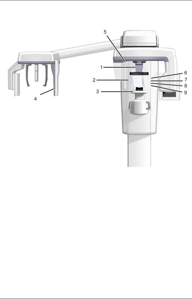
2.1Main parts and controls
1.Column
2.Carriage
3.Main support
4.Rotating unit
5.On/off switch (rear of carriage) and main fuses
6.Tubehead assembly
7.Touch screen display
8.Positioning panel
9.Sensor head
10.Head support 11.Chin rest 12.Handles 13.Cephalostat unit 14.Cephalostat sensor 15.Secondary collimator 16.Positioning panel
Fig 1.1. On/off switch and main fuses
PC with MDD approved dental imaging software and 3D viewing software (not included).
All software must conform to the MDD and the relevant legal requirements in the USA.
The PC must conform to all the unit and dental imaging software requirements.
210457 rev 7 |
Instrumentarium Dental |
9 |

2 Unit description
1.Sensor holder (units without 3D option)
2.Panoramic sensor
1.3D sensor (units with 3D option)
2.Panoramic sensor
10 |
Instrumentarium Dental |
210457 rev 7 |
2 Unit description
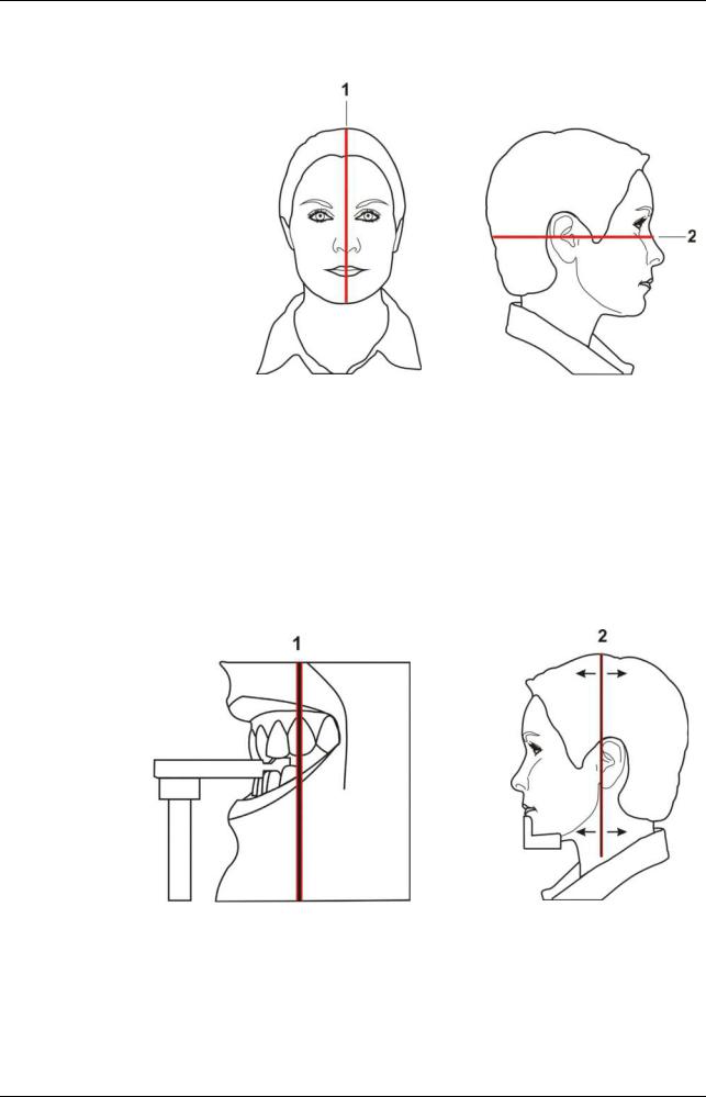
2.2 Patient positioning lights
1.Midsagittal light
2.Frankfort horizontal (FH) light /
Horizontal light, top of 130 mm high FOV (3D MFOV (Maxio) option only)
3.Image layer light
4.Cephalometric FH light
5.TMJ light
6.Horizontal light, top of 78 mm high FOV (3D MFOV (Maxio) option only)
7.Horizontal light, top of 61 mm high FOV (3D option only)
8.Horizontal light, top of 50 mm FOV (3D MFOV (Maxio) option only)
9.Horizontal light, bottom of FOV (3D option only)
210457 rev 7 |
Instrumentarium Dental |
11 |
2 Unit description
Panoramic lights
Fig 1.1.
1. Midsagittal light
2. FH light
Fig 1.2.
1. Image layer light
2. TMJ light
12 |
Instrumentarium Dental |
210457 rev 7 |
2 Unit description
Cephalometric lights
Fig 1.3.
1. FH light
3D lights (optional)
Note! Appropriate lasers are turned automatically on based on selected FOV.
Fig 1.4.
1.Midsagittal light
2.Horizontal light, top of FOV
Note! With 3D MFOV (Maxio) option height 130 mm is indicated with Frankfort horizontal (FH) light. Move FH light to 130 mm position (locked in up-position).
3.Horizontal light, bottom of FOV
210457 rev 7 |
Instrumentarium Dental |
13 |
2 Unit description
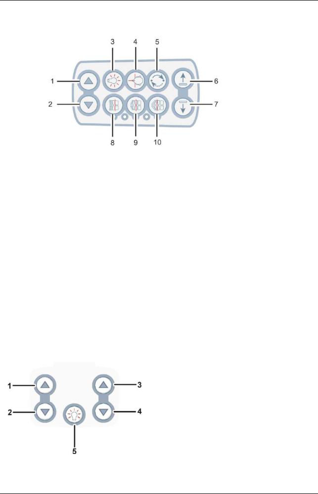
2.3 Patient positioning panel
Fig 1 5
1.Carriage UP
2.Carriage DOWN
3.Positioning lights ON/OFF
4.Patient positioning
5.Start positioning
6.Chin support UP
7.Chin support DOWN
8.Move the image layer anterior before exposure 3 mm, with sinus program 10 mm
9.Normal occlusion/ reset position
10.Move the image layer posterior before exposure 3 mm, with sinus program 10 mm
2.3.1Cephalometric unit (optional)
1.Carriage UP
2.Carriage DOWN
3.Carriage UP
4.Carriage DOWN
5.Positioning lights ON/OFF
14 |
Instrumentarium Dental |
210457 rev 7 |

2 Unit description
2.4 Emergency stop switch
In case of malfunction of the exposure button or other protective devices of the unit, an emergency stop switch is provided near the handles and on the roof of the cephalostat head so that the patient can reach it.
If the emergency stop switch is pressed during an exposure, the exposure is terminated immediately and the x-ray unit is completely stopped. An interrupted exposure cannot be continued later, but has to be retaken from the beginning.
Fig 1.6.
Fig 1.7.
Press to stop the unit, rotate to release.
210457 rev 7 |
Instrumentarium Dental |
15 |

2 Unit description
16 |
Instrumentarium Dental |
210457 rev 7 |

3Imaging programs
3.1Panoramic programs
Standard: Magnification 1.3
Exposure settings for panoramic program
100 VAC |
66 kV/5 mA |
66 kV/8 mA |
66 kV/10 mA |
70 kV/13 mA |
230 VAC |
66 kV/5 mA |
66 kV/8 mA |
66 kV/10 mA |
70 kV/13 mA |
|
|
|
< default > |
|
Pediatric: Magnification 1.3
Exposure settings for pediatric program
100 VAC |
66 kV/4 mA |
66 kV/6.3 mA |
66 kV/8 mA |
70 kV/10 mA |
230 VAC |
66 kV/4 mA |
66 kV/6.3 mA |
66 kV/8 mA |
70 kV/10 mA |
|
|
|
< default > |
|
210457 rev 7 |
Instrumentarium Dental |
17 |

3 Imaging programs
Pediatric patients can be imaged with less radiation dosage and shorter exposure time. Patients with jaw more narrow than average jaw can be exposed with this procedure too.
Ortho Zone: Magnification 1.25
The Ortho Zone program produces two different scanning geometries combined in the same image.
The first geometry (#1 and #3 in the figure) gives a standard panoramic view of the molar region.
The result of this scanning location will allow for views of the TM joint and molar area without redundant shadows from the opposite side ramus obscuring the image. Patients with prosthetic condyles or other posterior radio opaque objects can have the opposite side successfully imaged.
The second view (#2 in the figure) produces an image of the anterior region with a very wide layer of focus (approx.
35 mm). This view may be helpful when diagnosing trauma, wired shut, severe class III malocclusion and uncooperative patients.
Exposure settings for Ortho Zone program
100 VAC |
66 kV/5 mA |
66 kV/8 mA |
66 kV/10 mA |
70 kV/13 mA |
230 VAC |
66 kV/5 mA |
66 kV/8 mA |
66 kV/10 mA |
70 kV/13 mA |
|
|
|
< default > |
|
18 |
Instrumentarium Dental |
210457 rev 7 |

3 Imaging programs
Orthogonal: Magnification 1.3
An optimized view of the dentition only with optimized angulation and reduced radiation.
Orthogonal program produces a panoramic view with modified projection geometry. The Y axis of the rotation path is changed to improved the beam angle to be closer to 90° to the interproximal surfaces. With this improvement, other trade off's must be made. The ascending rami may
Y be lost and in adult patients and redundant shadows will be increased.
Exposure settings for Orthogonal program
100 VAC |
66 kV/5 mA |
66 kV/8 mA |
66 kV/10 mA |
70 kV/13 mA |
230 VAC |
66 kV/5 mA |
66 kV/8 mA |
66 kV/10 mA |
70 kV/13 mA |
|
|
|
< default > |
|
Wide arch: Magnification 1.3
Used when the patient has a wider than normal dental arch.
Exposure settings for Wide arch program
100 VAC |
66 kV/5 mA |
66 kV/8 mA |
66 kV/10 mA |
70 kV/13 mA |
230 VAC |
66 kV/5 mA |
66 kV/8 mA |
66 kV/10 mA |
70 kV/13 mA |
|
|
|
< default > |
|
210457 rev 7 |
Instrumentarium Dental |
19 |

3 Imaging programs
Ortho Lateral TMJ: Magnification 1.23
a |
b |
Ortho TMJ program provides a wide layer axially corrected views for the patient's left and right temporomandibular joints.
Exposure settings for Ortho Lateral TMJ program
100 VAC |
73 kV/6.3 mA |
73 kV/10 mA |
73 kV/13 mA |
73 kV/16 mA |
230 VAC |
73 kV/6.3 mA |
73 kV/10 mA |
73 kV/13 mA |
73 kV/16 mA |
|
|
|
< default > |
|
PA TMJ: Magnification 1.55
Exposure settings for PA TMJ program
100 VAC |
73 kV/6.3 mA |
73 kV/10 mA |
73 kV/13 mA |
73 kV/16 mA |
230 VAC |
73 kV/6.3 mA |
73 kV/10 mA |
73 kV/13 mA |
73 kV/16 mA |
|
|
|
< default > |
|
20 |
Instrumentarium Dental |
210457 rev 7 |
3 Imaging programs
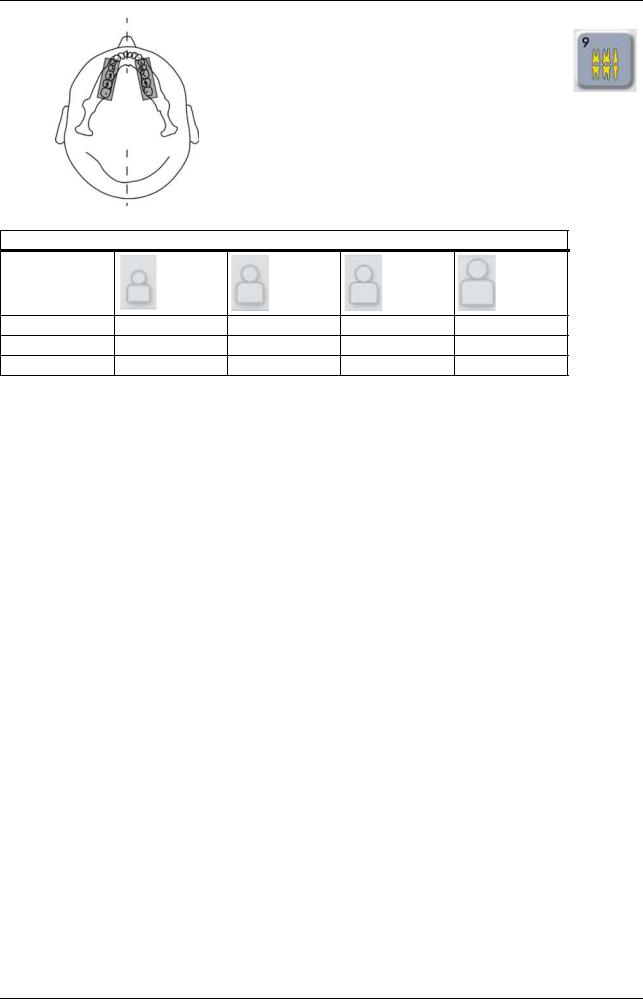
Maxillary Sinus: Magnification 1.3
Mesial 10 mm |
Start |
Distal 10 mm |
Maxillary Sinus program produces a pan - tomographic layer through the posterior maxillary sinus. The layer is flatter than the standard panoramic programs and is moved 18 mm backward. These images are helpful in visualizing the mid and posterior maxillary sinus.
Exposure settings for Maxillary Sinus program
100 VAC |
66 kV/6.3 mA |
66 kV/10 mA |
66 kV/13 mA |
73 kV/13 mA |
230 VAC |
66 kV/6.3 mA |
66 kV/10 mA |
66 kV/13 mA |
73 kV/13 mA |
|
|
|
< default > |
|
210457 rev 7 |
Instrumentarium Dental |
21 |
3 Imaging programs
Bitewing: Magnification 1.3
An orthogonal view of the dentition from the canine and posterior.
Exposure settings for Bitewing program
100 VAC |
66 kV/5 mA |
66 kV/8 mA |
66 kV/10 mA |
70 kV/13 mA |
230 VAC |
66 kV/5 mA |
66 kV/8 mA |
66 kV/10 mA |
70 kV/13 mA |
|
|
|
< default > |
|
22 |
Instrumentarium Dental |
210457 rev 7 |
Loading...