

Instrumentarium Dental OP-200D, OC-200D User Manual

ENGLISH
Orthopantomograph
®
OP200 D
Orthoceph® OC200 D
User Manual
5139796-100 rev. 7


Copyright Code: 5139796-100 rev 7 Date: 27 September 2012
Document code: D500319 rev 7
Copyright © 09/2012 by PaloDEx Group Oy.
All rights reserved.
Orthopantomograph® and Orthoceph® are registered trademarks
of Instrumentarium Dental. U.S. patents 6,731,717, 6,829,326
and USRE41197. Finnish patents 114383. Windows
trademark of Microsoft Corporation in the United States of
®
America and other countries. Pentium
®
of Intel Corporation. Iomega
Jaz® is a registered trademark of
is a registered trademark
Iomega Corp.
Documentation, trademark and the software are copyrighted
with all rights reserved. Under the copyright laws the
documentation may not be copied, photocopied, reproduced,
translated, or reduced to any electronic medium or machine
readable form in whole or part, without the prior written
permission of Instrumentarium Dental.
The original language of this manual is English.
®
is
Instrumentarium Dental reserves the right to make changes in
specification and features shown herein, or discontinue the
product described at any time without notice or obligation.
Contact your Instrumentarium Dental representative for the most
current information.
Manufactured by Instrumentarium Dental, PaloDEx Group Oy
Nahkelantie 160 (P.O. Box 20)
FI-04300 Tuusula
FINLAND
Tel. +358 10 270 2000
Fax. +358 9 851 4048
For service, contact your local distributor.


Table of Contents
1 Introduction.................................................................................................................. 1
1.1 General ................................................................................................................. 1
1.2 Markings and graphics symbols............................................................................ 2
1.3 Type and version................................................................................................... 3
1.4 Options, accessories and manuals ....................................................................... 5
1.5 Radiation protection guidelines ............................................................................. 6
1.5.1 Protection by distance................................................................................ 6
1.5.2 Laser lights................................................................................................. 7
1.5.3 Control from a protected environment........................................................ 7
1.5.4 Emergency Stop Switch ............................................................................. 8
1.6 Manufacturer’s liability........................................................................................... 8
1.7 Disposal ................................................................................................................ 9
2 OP200 D controls and accessories.......................................................................... 11
2.1 OP200 D main parts............................................................................................ 11
2.2 OC200 D Main parts ........................................................................................... 15
2.3 Control panel....................................................................................................... 16
2.4 Positioning panels ...............................................................................................19
2.5 Patient positioning accessories........................................................................... 20
2.6 Disposables & Service accessories .................................................................... 22
2.7 Changing the fuses ............................................................................................. 24
3 Equipment care and preparations............................................................................ 25
3.1 Care Instructions ................................................................................................. 25
3.2 Cleaning recommendations ................................................................................ 25
3.2.1 Cleaning ................................................................................................... 25
3.2.2 Disinfection and sterilization..................................................................... 26
3.2.2.1 Autoclave................................................................................... 26
3.2.2.2 Steam sterilization ..................................................................... 26
3.2.2.3 Ethylene oxide sterilization ........................................................ 27
3.2.3 Other sterilization processes.................................................................... 27
3.2.3.1 Dry heat sterilization .................................................................. 27
3.2.3.2 Liquid chemical sterilant gases.................................................. 27
3.2.3.3 Chemical sterilant gases............................................................ 27
3.3 Connecting and disconnecting the CCD sensor .................................................28
3.4 Preparation for panoramic image acquisition...................................................... 30
3.5 Selecting collimator height with automatic collimator.......................................... 32
4 Panoramic procedures.............................................................................................. 33
4.1 P1: Standard panoramic exposure...................................................................... 33
4.2 P2: Pediatric panoramic exposure ...................................................................... 41
4.3 P3: Ortho Zone enhanced panoramic exposure ................................................. 44
4.4 P4: Orthogonal exposure .................................................................................... 46
4.5 P5: Wide arch panoramic exposure ....................................................................48
5 Special imaging procedures.....................................................................................51
5.1 BW: Bitewing exposure .......................................................................................51
5.2 P6: TMJ, Lateral projection ................................................................................. 52
5139796-100 rev 7 Instrumentarium Dental i

5.3 P6: Ortho TMJ, axial corrected lateral projection (optional) ................................ 56
5.4 P7: TMJ, posterioranterior projection ..................................................................60
5.5 P8: Maxillary Sinus view ..................................................................................... 61
6 Cephalometric procedures (optional)...................................................................... 65
6.1 Preparing the operation....................................................................................... 65
6.2 P9a: Cephalo Core Lateral projection
P9b: Lateral projection ........................................................................................ 65
6.3 P10: Cephalo postero-anterior (PA) projection ................................................... 68
6.4 P10: Reverse Towne projection exposure .......................................................... 70
6.5 P10: Waters view exposure ................................................................................ 71
6.6 P10: Carpus view exposure (holder optional) .....................................................72
7 Imaging technique..................................................................................................... 75
7.1 Automatic exposure control (AEC)...................................................................... 75
7.2 AEC test .............................................................................................................. 76
7.3 Exposure technique factors................................................................................. 76
7.4 Manual mode ...................................................................................................... 78
7.5 Free selection of kV and mA ...............................................................................79
7.6 Test mode ........................................................................................................... 80
7.7 Measurements from the image ........................................................................... 81
8 Special features ......................................................................................................... 83
8.1 Basic quality assurance ...................................................................................... 83
8.2 Advanced QA (optional) ......................................................................................84
8.3 Exposure counter ................................................................................................85
8.4 Preventive maintenance reminder ...................................................................... 85
9 Understanding the OP200 D image.......................................................................... 87
10 Failure diagnostics ................................................................................................... 89
10.1 Failure messages................................................................................................ 89
10.2 kV display............................................................................................................ 89
10.3 mA display........................................................................................................... 90
10.4 Time display ........................................................................................................ 90
10.5 Resetting a failure ............................................................................................... 90
10.6 Failure codes....................................................................................................... 92
11 Diagnosing image quality problems .......................................................................93
11.1 Patient positioning problems ...............................................................................93
11.2 Image appearance problems ..............................................................................96
11.3 Artefacts .............................................................................................................. 97
11.4 Unit operation...................................................................................................... 98
12 How to use the user programming mode............................................................. 101
12.1 General ............................................................................................................. 101
12.2 Installation and unit configuration programs .....................................................101
12.3 Programs affecting image quality...................................................................... 102
12.4 Other Pr programs ............................................................................................ 103
12.5 How to use the user programming mode .......................................................... 103
ii Instrumentarium Dental 5139796-100 rev 7

13 User program features ...........................................................................................105
13.1 Pr 50 S3d: Volumetric Tomography settings..................................................... 105
13.2 Pr 51 PUS: Power up settings........................................................................... 106
13.3 Pr 52 PCo and Pr 52 gCo:
Constant contrast & density settings................................................................. 106
13.4 Pr 53 nor: Resume normal settings................................................................... 109
13.5 Pr 54 Arn: Rotating unit autoreturn ................................................................... 110
13.6 Pr 57 Hon: Patient positioning side ................................................................... 110
13.7 Pr 58 CON: Vertebrae shadow compensation ..................................................111
13.8 Pr 59 PSE: Preventative maintenance reminder............................................... 113
13.9 Pr 60 bEP: Panel beep...................................................................................... 114
13.10 Pr 61 CLC: Clear exposure counter................................................................. 115
13.11 Pr 62 ERR: Last failure code ........................................................................... 115
13.12 Pr 63 CEL: Cephalostat exposure limit............................................................ 116
13.13 Pr 64 FSt: Fast scanning selection .................................................................. 116
13.14 Pr 65 doS: Dose / time display selection ......................................................... 117
13.15 Pr 66 COU: Exposure counters ....................................................................... 119
13.16Pr 67 qUA: Quality assurance .......................................................................... 120
14 User statement........................................................................................................ 121
14.1 Dose area product (DAP).................................................................................. 126
15 Technical specifications ........................................................................................ 129
15.1 Electromagnetic Compatibility (EMC) tables..................................................... 138
16 Maintenance ............................................................................................................ 145
16.1 Maintenance Schedule...................................................................................... 145
16.2 Monthly Inspection by User............................................................................... 145
16.3 Preventive maintenance Reminder ...................................................................146
5139796-100 rev 7 Instrumentarium Dental iii

iv Instrumentarium Dental 5139796-100 rev 7

1 Introduction
1.1 General
INSTRUMENTARIUM DENTAL® Orthopantomograph
OP200 D panoramic unit (hereafter called “OP200 D”) is a
software controlled diagnostic panoramic dental X-ray
equipment for producing high quality digital images of
dentition, TM-joints and skull. In order to take images with
OP200 D you need a suitable PC hardware connected to
the OP200 D unit and CLINIVIEWTM software to handle
images.
OP200 D performs the following procedures:
Standard panoramic exposure
Pediatric panoramic exposure
Ortho Zone enhanced panoramic exposure
Wide arch panoramic exposure
Orthogonal panoramic exposure
Maxillary sinus
TMJ, lateral projection or
Ortho TMJ axial corrected lateral projection (optional)
TMJ, PA projection
Bitewing exposure
®
Orthoceph® OC200 D is a more equipped x-ray panoramic
unit with cephalometric exposure option (hereafter called
“OC200 D”) . In addition to the OP200 D functions OC200
D performs the following cephalometric procedures:
lateral view
posterior-anterior (PA) and anterior-posterior (AP)
views
The basic OP200 D can be upgraded later to the
Orthoceph® OC200 D.
A minimum complete system contains the X-ray unit itself
(with all of its accessories) and the modality workstation
(PC) that is connected to the unit. However note that where
as the rest of the system is installed to the patient
environment, the modality workstation or any other PC
may have restrictions to the place of installation referenced
to that environment.
As the manufacturer we strongly recommend that you read
this manual before taking the unit into use.
5139796-100 rev 7 Instrumentarium Dental 1
1 Introduction
NOTE! OP200 D Must be installed according to the
OP200 D installation & Adjustments manual by a
qualified technician. Only trained personnel should
be allowed to operate OP200 D.
1.2 Markings and graphics symbols
The following symbols are used in OP200 D:
Radiographic control
Protective earth (ground)
Type B equipment
GOST-R A certification that the products
qualifies for safety requirements in Russia
Dangerous voltage
On (Power)
Off (Power)
Attention, consult accompanying documents
If the unit has CE-marking it is CE-marked
according to the Medical Device Directive 93/
42/EEC.
ETL symbol
This symbol indicates that the waste of
electrical and electronic equipment must not
be disposed as unsorted municipal waste and
must be collected separately. Please contact
an authorized representative of the
manufacturer for information concerning the
decommissioning of your equipment.
2 Instrumentarium Dental 5139796-100 rev 7
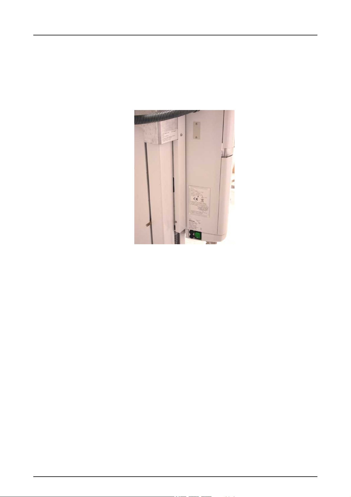
1.3 Type and version
The type and version of OP200 D is defined in the main
label of the unit located on the vertical carriage bottom
plate next to the power on/off switch or in the column label
of the unit located on the column. The unit is class I, type B
and with IP-20 protection.
1 Introduction
Fig 1.1. Location of main label and CE mark
5139796-100 rev 7 Instrumentarium Dental 3

1 Introduction
The type and version of the unit can be read from the main
label or column label codes. The type numbers appear in
the following form: OP200 D-a-bc-d-S.
TYPE AND VERSION
OP200 D
OC200 D
a
bc
d
short form for ORTHOPANTOMOGRAPH®
OP200 D
short form for ORTHOCEPH® OC200 D
type of the x-ray tube insert which is originally
utilized:
1 = Toshiba D-051S
the type of Panoramic sensor (b) and Cephalostat
sensor (c):
0 = No sensor = No type number
1 = PAN sensor, fixed
2 = PAN sensor, removable
3 = CEPH sensor, fixed
4 = PAN / CEPH sensor, removable
NOTE: Number can be for example “24” meaning
both PAN sensor and PAN/CEPH sensor.
version number:
1 = OP200 models starting from s/n 100 000
S
indication of a "Special" version, marked only in
products which have a non-standard modification
For example, OP200 D-1-4-1 is:
®
(OP200 D) Orthopantomograph
OP200 D
(-1) with Toshiba D-051S tube
(-4) Removable combined panoramic and cephalostat
sensor
(-1) first version of OP200.
4 Instrumentarium Dental 5139796-100 rev 7

1 Introduction
1.4 Options, accessories and manuals
The options are listed in the appendices. The accessories
are listed in sections 2.5 and 2.6. All standard items and
approved accessories are suitable for use within the
patient environment.
WARNING! This product itself complies IEC601-1-1
medical safety standard but in order to the system
incorporating also a PC to comply the standard, EITHER
the PC has to be a medical PC OR the PC has to be
located over 1,5 meters apart from the OP/OC200 D unit.
The installer and the user of the system shall confirm that
at least one of the above requirements is fulfilled. A PC is a
medical one if it complies IEC 601-1standard and that is
indicated in the accompanying documents of the PC.
NOTE! In order to maintain safe and correct functioning of
OP200 D, only the approved accessories may be used.
CAUTION! Use of controls or adjustments or performance
of procedures other than those specified herein may result
in hazardous radiation exposure.
Following manuals and documents are shipped with the
OP200 D:
OP200 D / OC200 D
Installation & Adjustments Manual
OP200 D / OC200 D User Manual
Installation & User Manual for CLINIVIEWTM software
These manuals and future updates are available on
request from the manufacturer.
5139796-100 rev 7 Instrumentarium Dental 5

1 Introduction
1.5 Radiation protection guidelines
X-ray equipment may cause injury if used improperly. The
instructions contained in this manual must be read and
followed when operating the Orthopantomograph® OP200
D. All government and local regulations pertaining to
radiation safety must be observed.
NOTE! For USA: Many provisions of these regulations are
based on recommendations of the National Council on
Radiation Protection and Measurements.
Recommendations for dental x-ray protection are
published in NCRP Report #35 available from NCRP
Publications, 7910 Woodmont Avenue, Suite 1016,
Bethesda, MD 20814.
Personal radiation monitoring and protective devices are
available and recommended for staff members. It is also
recommended to provide the patient with a protective
apron. Consult the physician before taking images of
pregnant patients.
WARNING! OP200 D must not be used in rooms where an
explosion hazard exists. Equipment not suitable for use in
the presence of flammable mixtures.
OP200 D with radiation protection in accordance with
IEC601-1-3:1994.
1.5.1 Protection by distance
In all examinations the user of the x-ray equipment should
wear protective clothing. The operator does not need to be
close to the patient during normal use. The protection
against stray radiation can be achieved by using the hand
switch not less than 2 m (7 ft) from the focal spot and the xray beam. Operator should maintain visible contact with
the patient and technique factors. This allows immediate
termination of radiation by the release of the exposure
button in the event of a malfunction or disturbance.
Caution information on control panel:
CAUTION X-RAYS
ATTENTION
RAYONS X
WARNING:
This x-ray unit may be dangerous to patient and operator
unless safe exposure factors, operating instructions and
maintenance schedules are observed.
6 Instrumentarium Dental 5139796-100 rev 7
1.5.2 Laser lights
1 Introduction
Fig 1.2. Laser light (CLASS 1 LASER PRODUCT). Max output 100µW.
1.5.3 Control from a protected environment
The control panel hand switch or optional remote hand
switch can be used from an environment protected from
the x-ray radiation. The fully extended spiral cable length of
the control panel hand switch is approx. 4 m (13 ft). The
cable length of the remote hand switch (part no. 69961) is
approx. 10 m (32 ft).
5139796-100 rev 7 Instrumentarium Dental 7
1 Introduction
1.5.4 Emergency Stop Switch
In case of malfunction of the exposure button release or
other protective devices of the unit, an emergency stop
switch is provided on the right side of the unit so that the
patient can reach it. If the emergency stop switch is
pressed during an exposure, the exposure is terminated
immediately and the x-ray unit is completely stopped. An
interrupted exposure cannot be continued later, but has to
be retaken from the beginning.
1.6 Manufacturer’s liability
As a manufacturer we can only assume liability of safe and
reliable operation of this unit when
OP200 D unit installation was performed according to
the OP200 D Installation & Adjustments Manual and
OP200 D Unit is used according to the OP200 D User
Manual
CLINIVIEWTM PC software was installed according to
the Installation Manual for CLINIVIEWTM software.
CLINIVIEWTM software is used according to User
Manual for CLINIVIEWTM software.
Maintenance and repairs are performed by a qualified
Orthopantomograph® Dealer and
Original or authorized spare parts are used
In order to guarantee maximal image quality for the entire
life time of this high performance imaging system, we
suggest that a special image quality assurance procedure
(* and test object designed for image quality assurance
8 Instrumentarium Dental 5139796-100 rev 7

1 Introduction
purposes is used (code 68795). Also we recommend that a
qualified serviceman to check the unit to be in its original
condition regarding electrical, radiation and mechanical
safety according to our maintenance program described in
more details in maintenance manual (code 61049) every
year or after 2000 images. For more information please
contact your local dealer.
*) According to EN61223-3-4 and DIN 6868-151
If service on the unit is performed, a work order describing
the type and extent of repair must be provided by the
service technician. This must contain information of
changes of nominal data or work range performed. The
work order must furthermore indicate the date of repair, the
name of the company concerned and a valid signature.
User should keep this work order for future references.
NOTE! Only use PC hardware that has been tested to be
compatible with the OP 200 D PCI board and
CLINIVIEWTM software.
NOTE! Certain changes to the hardware may void the
compatibility. Contact your local dealer for up-to-date
information on this matter.
1.7 Disposal
At the end of useful service life of the device, its spare
parts, its replacement parts and its accessories make sure
that you follow all local, national and international
regulations regarding the correct and safe disposal and/or
recycling of the device, its spare parts, its replacement
parts and its accessories.
The device, its spare parts, its replacement parts and its
accessories may include parts that are made of or include
materials that are non-environmentally friendly or
hazardous. These parts must be disposed of in
accordance with all local, national and international
regulations regarding the disposal of non-environmentally
friendly or hazardous materials.
The locations of all parts that are made of or include
materials that are non-environmentally friendly or
hazardous can be found in the device service manual.
5139796-100 rev 7 Instrumentarium Dental 9

1 Introduction
10 Instrumentarium Dental 5139796-100 rev 7
2 OP200 D controls and accessories
1
2
3
4
5
6 7
8
9
10
11
12
13
Optional cephalostat
2 OP200 D controls and accessories
WARNING! Do not stack or locate the unit close to other
equipment.
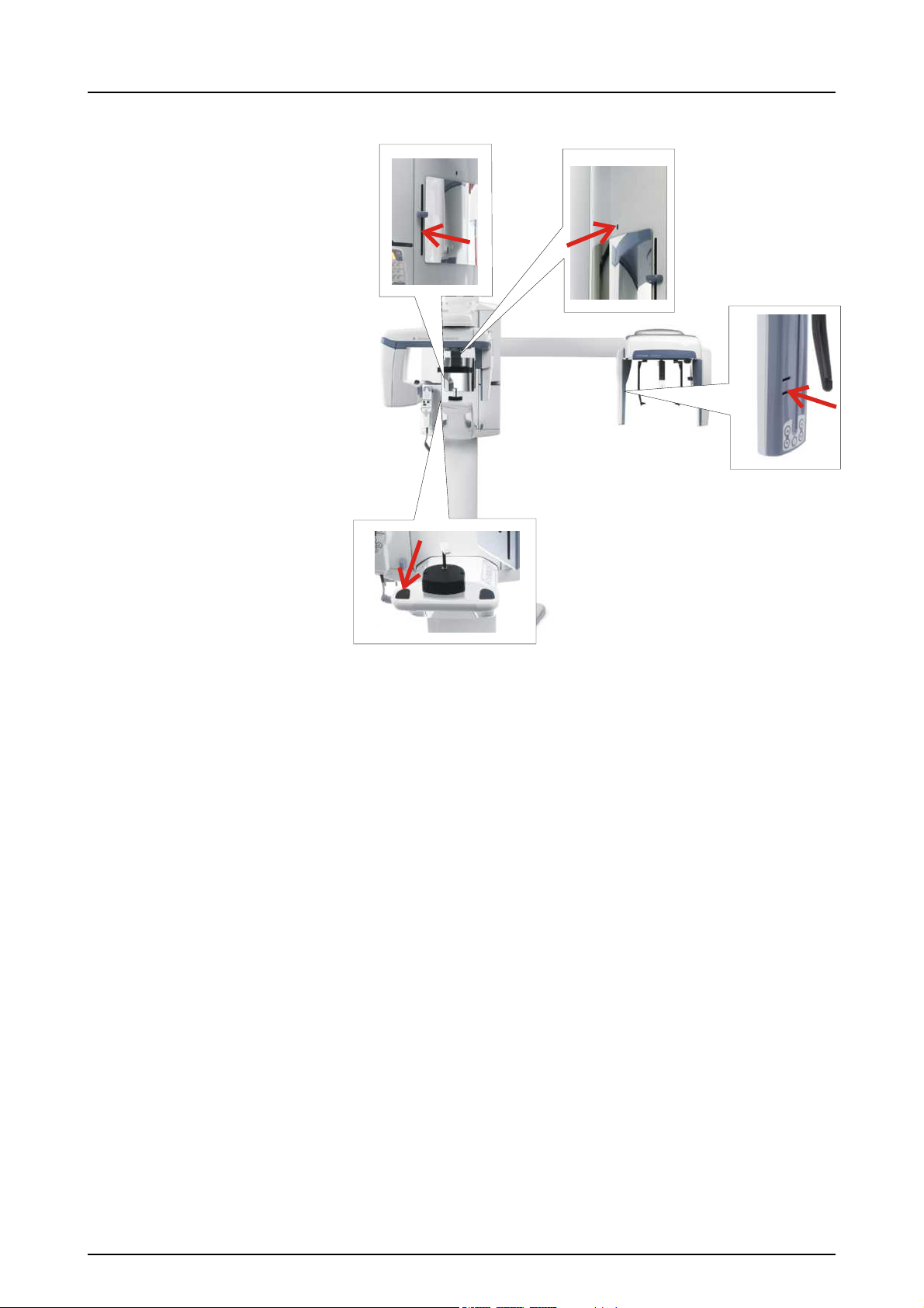
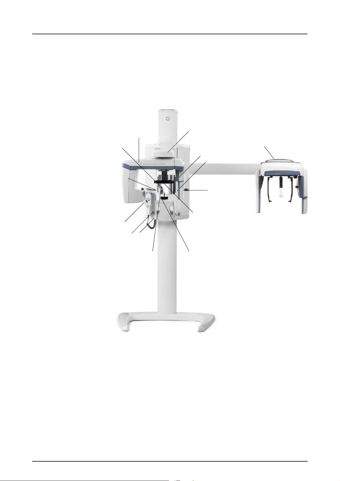
2.1 OP200 D main parts
1. CCD sensor
2. CCD sensor holder
3. Main support
4. Rotating unit
5. Head and Temple support
6. Bite fork with rod
7. Chin rest
8. Handles
9. Positioning panel
5139796-100 rev 7 Instrumentarium Dental 11
2 OP200 D controls and accessories
15
10. Control panel
11. Exposure indicator lights
12. FH laser (CLASS 1 LASER PRODUCT) light height
adjustment
13. Mirror
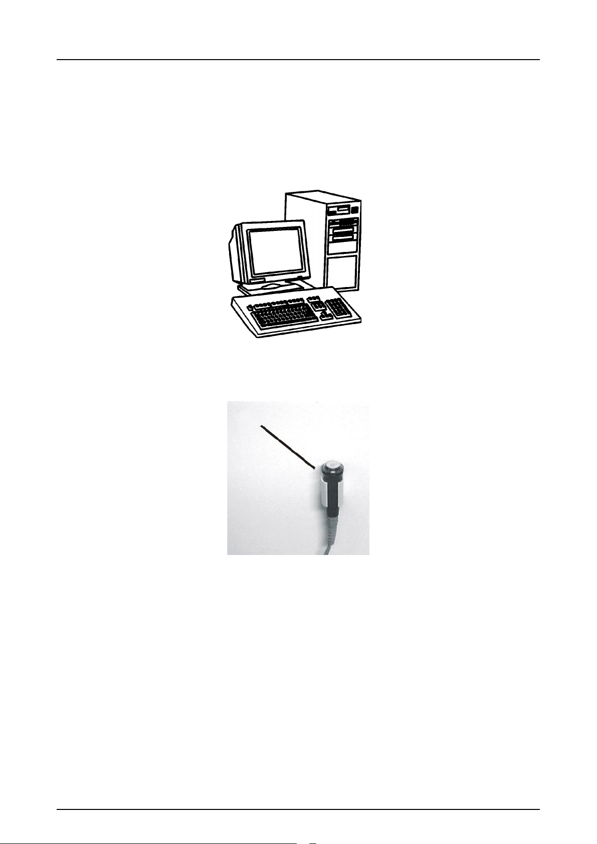
14. PC equipment
Fig 2.3. PC equipment
15. Remote exposure button and holder
(optional in some markets)
Fig 2.4. Remote exposure button
12 Instrumentarium Dental 5139796-100 rev 7
2 OP200 D controls and accessories
19
18
17
16
21
20
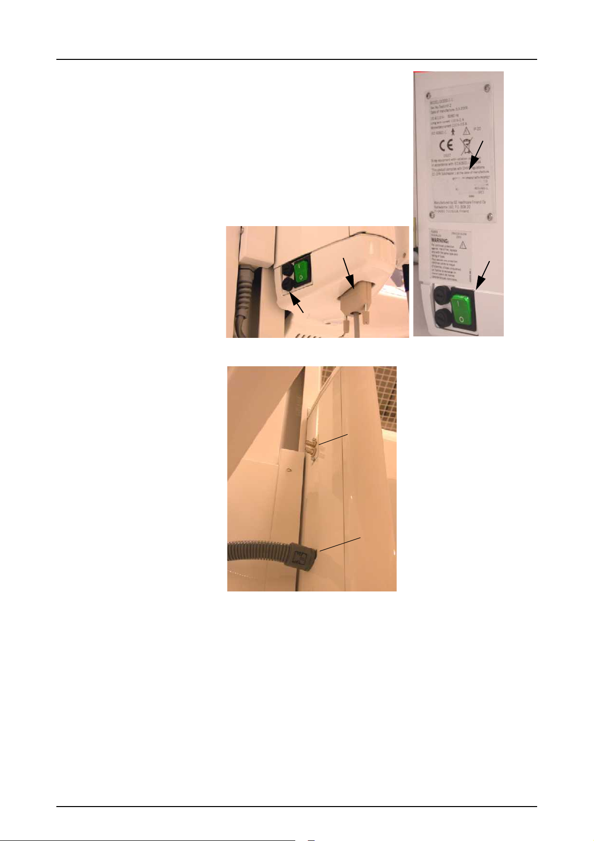
Fig 2.5. Carriage bottom plate and unit main label
Fig 2.6. Optical fibre connectors in OP200 D
5139796-100 rev 7 Instrumentarium Dental 13

2 OP200 D controls and accessories
25
2
2322
Fig 2.7. Optical fibre connectors in PC
16. Main label
17. Power ON / OFF switch with an indicator
NOTE! When unit has been switched ON, wait about one
minute until the unit is ready to exposure.
18. Main fuses with label
19. Connector for Control panel
20. Optical fiber link connectors at OP200 D (transmitter
and receiver)
21. Cephalostat main cable (only in OC200 D units)
22. Optical fiber link connectors at PCI card (transmitter
and receiver)
23. PCI board status leds
14 Instrumentarium Dental 5139796-100 rev 7
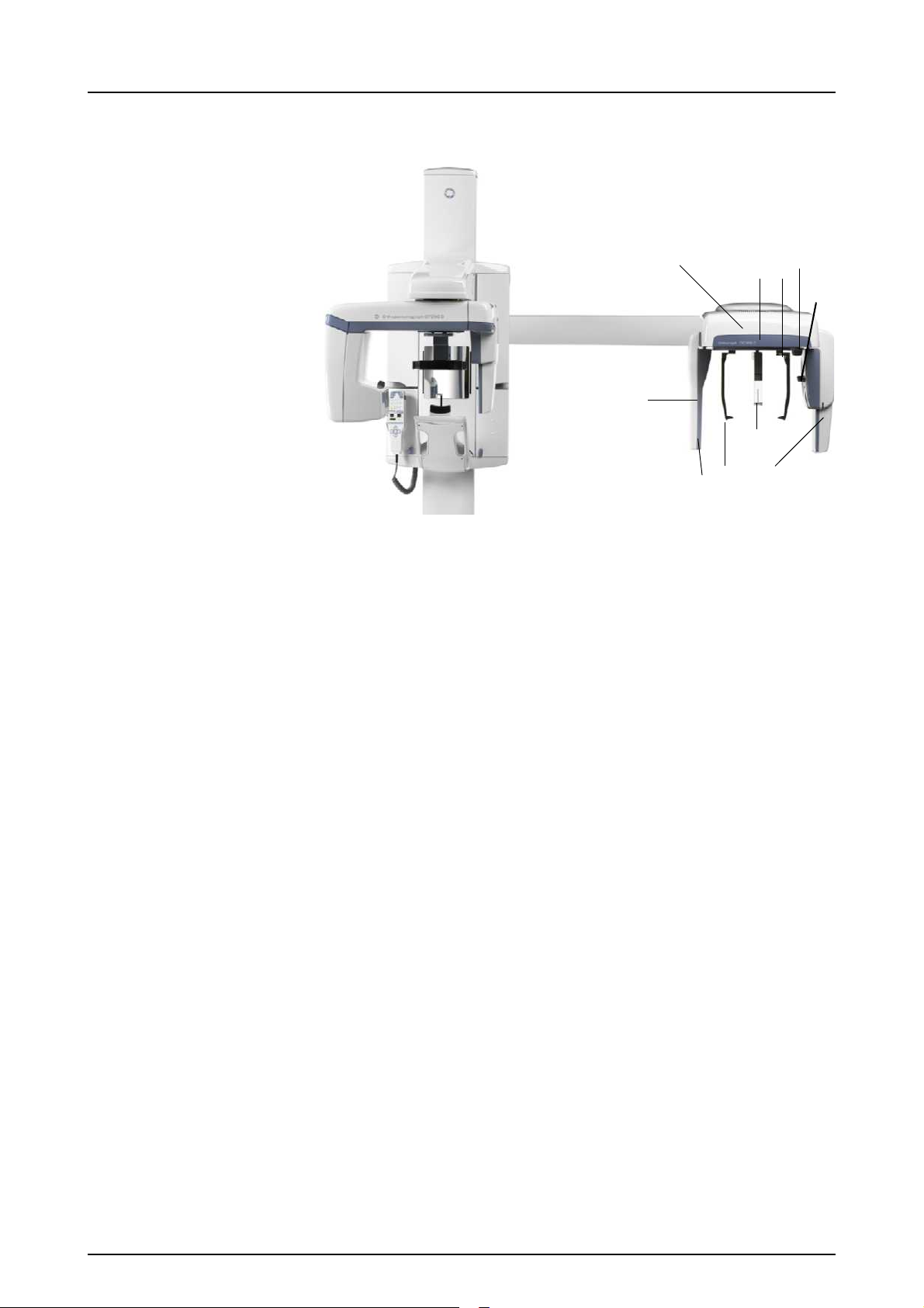
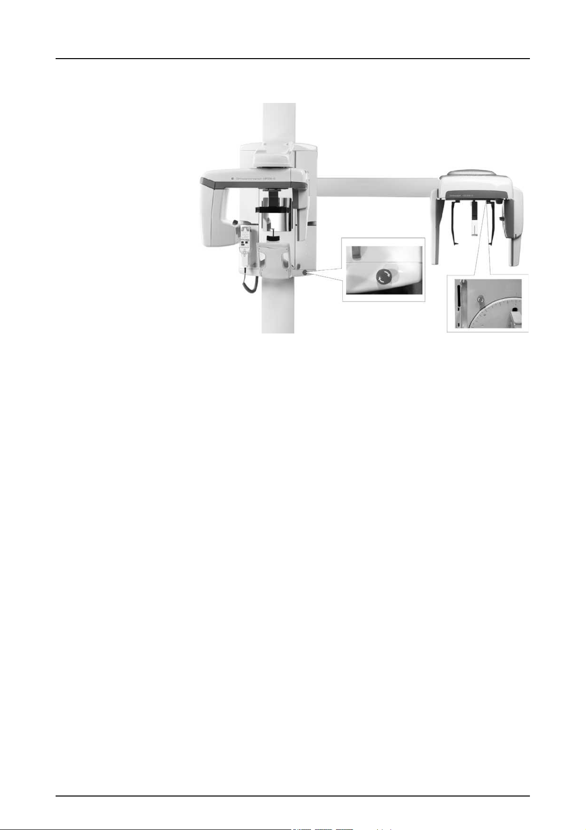
2.2 OC200 D Main parts
1
2
3
4
5
6
7
8
9
2
2 OP200 D controls and accessories
1. Cephalostat head
2. Control buttons
3. CCD sensor
4. Secondary collimator
5. Ear rod with pin
6. Nasion support with scale
7. Locking knob for ear rod rotation
8. Ear rod brake release button
9. Knob for raising and lowering the CCD sensor
5139796-100 rev 7 Instrumentarium Dental 15
2 OP200 D controls and accessories
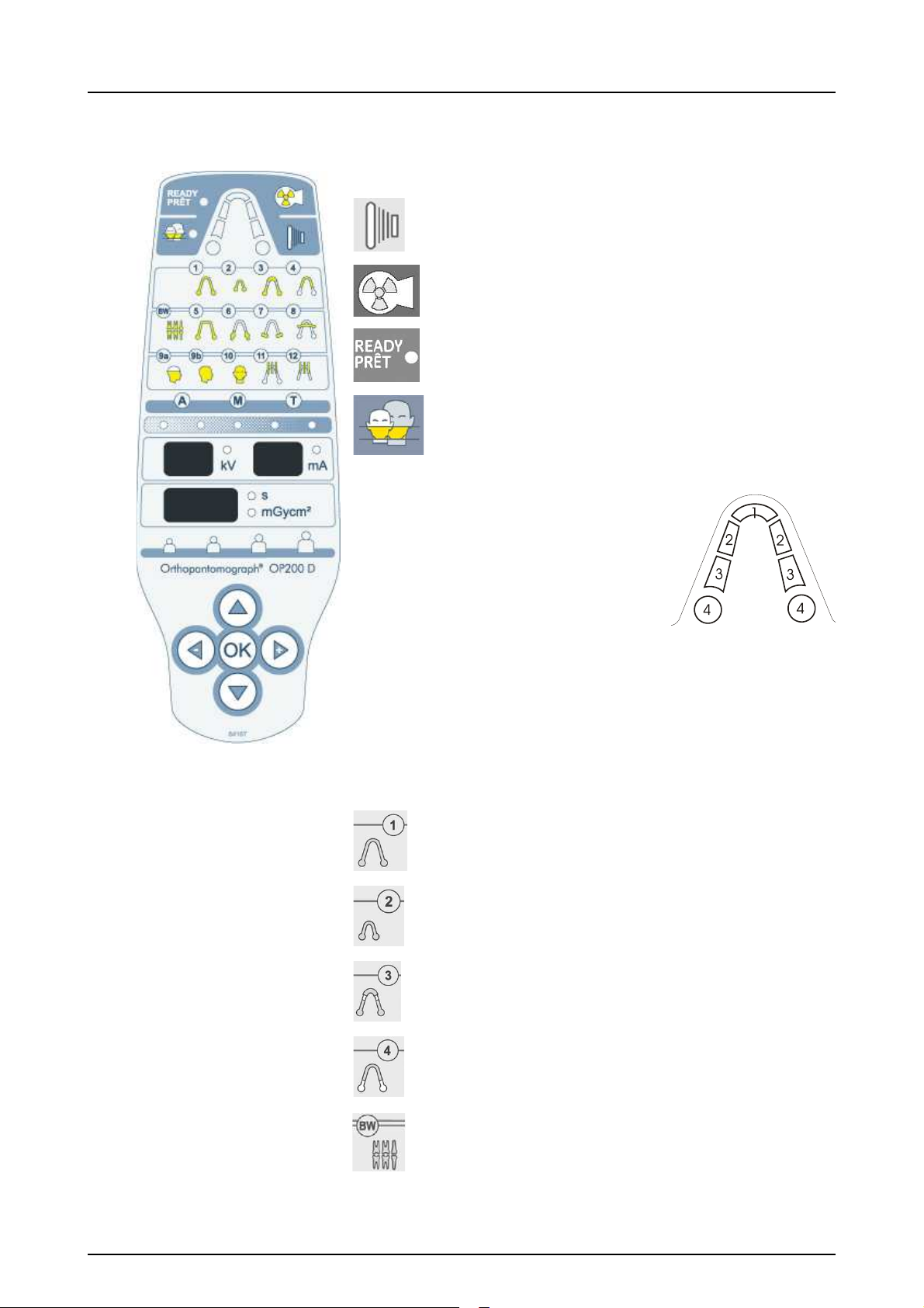
2.3 Control panel
Exposure Control
Exposure Button
Exposure Indicator light
“Ready” Indicator light
Pediatric Collimator light
Sections
1. Anterior
2. Premolar
3. Molar
4. Jaw joint
NOTE! Sections 2 and 3 are combined as one section in
panoramic programs.
Imaging Procedures P1-P12 with Indicator lights
Standard Panoramic (P1)
Pediatric Panoramic (P2)
Ortho Zone enhanced
Panoramic (P3)
Orthogonal Panoramic (P4)
Bitewing (BW)
16 Instrumentarium Dental 5139796-100 rev 7
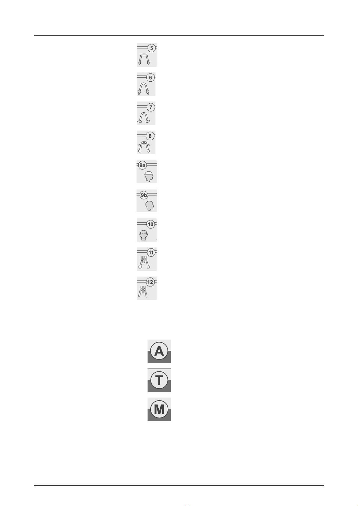
2 OP200 D controls and accessories
Wide arch Panoramic (P5)
TMJ lateral projection (P6) or
Ortho TMJ, axial corrected
lateral projection (optional) (P6)
TMJ, posterior-anterior
projection (P7)
Maxillary Sinus View (P8)
Cephalo Core Lateral
Projection (P9a)
Cephalo Lateral Projection
(P9b)
Cephalo Postero-Anterior (PA)
projection (P10)
Volumetric Tomography
mandible (optional) (P11)
Volumetric Tomography maxilla
(optional) (P12)
Exposure Modes with Indicator lights
Automatic Exposure Control
Test Mode
Manual Exposure Control
5139796-100 rev 7 Instrumentarium Dental 17
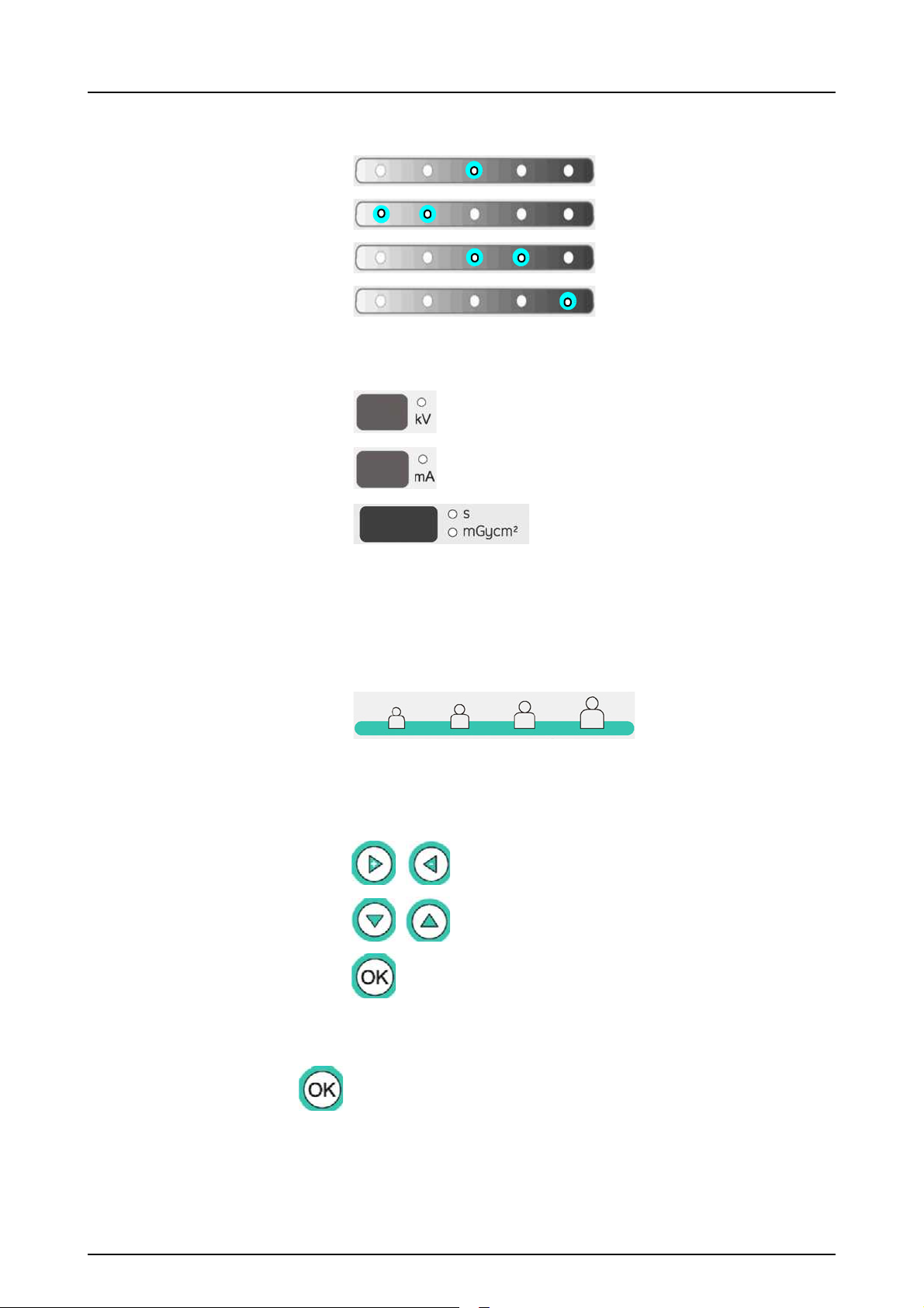
2 OP200 D controls and accessories
Automatic exposure signal to noise ratio
(9 dose control steps)
Default Signal to Noise
ratio
Decrease dose by one
and half step
Half step higher dose
Displays showing exposure values
kV display
mA display
Exposure time display /
Radiation dose display
Icons for Pre-programmed Technique Factors with
Indicator lights
Child - Juvenile - Adult - Large adult
Function Selection buttons:
Move the flashing indicator to left or right /
decrease or increase the value on display
Move the flashing indicator up or down to
the next selection row
P1-P10: Show exposure counter value
P11-P12: Show projection angle and
number of images
All programs: Clear errors
NOTE! The OK button is also used for entering and exiting
programming mode. See chapter User program features
for details.
18 Instrumentarium Dental 5139796-100 rev 7
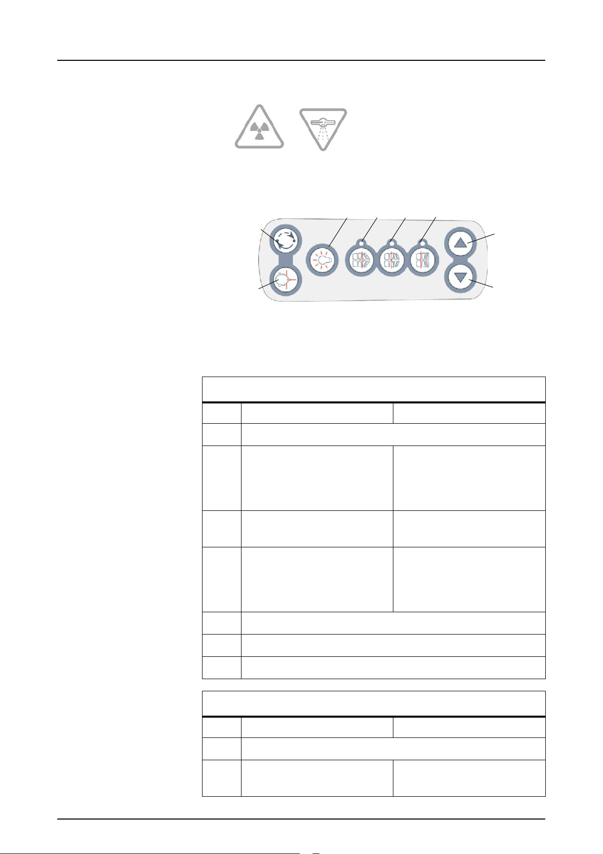
Radiation warning
26
25
24
23 22
21
20
20
2.4 Positioning panels
Fig 2.8. Positioning panel, right side
(on left side just the buttons 25 and 26 are flipped)
2 OP200 D controls and accessories
Positioning Panel button meaning in each mode
Key Panoramic(P1-P5) Maxillary Sinus (P8)
20
21 moves the image layer 3
mm anterior during
exposure
(retrusion)
22 normal occlusion/reset
Carriage movement up and down
moves the image layer
10 mm anterior from
nominal position during
exposure
nominal position
position
23 moves the image layer 3
mm posterior during
exposure
(protrusion)
24
25
26
Positioning lasers (CLASS 1 LASER PRODUCT) on/off
Rotating unit movement: Start positioning
Rotating unit movement: Patient positioning
moves the image layer
10 mm posterior from
nominal position during
exposure
Positioning Panel button meaning in each mode
Key Cephalometric (P9-P10) TMJ (P6-P7)
20
Carriage movement up and down
21 No functioning moves image layer
anterior
5139796-100 rev 7 Instrumentarium Dental 19
2 OP200 D controls and accessories
Positioning
light button
Down movement
Up movement
64197
68758
Fig 2.10. Panoramic patient positioning accessories
22 No functioning reset to middle
23 No functioning moves image layer
Positioning Panel button meaning in each mode
posterior
24
25
26
Postioning lasers (CLASS 1 LASER PRODUCT) on / off
Rotating unit movement: Start positioning
Rotating unit movement: Patient positioning
Fig 2.9. Positioning panel, cephalostat head
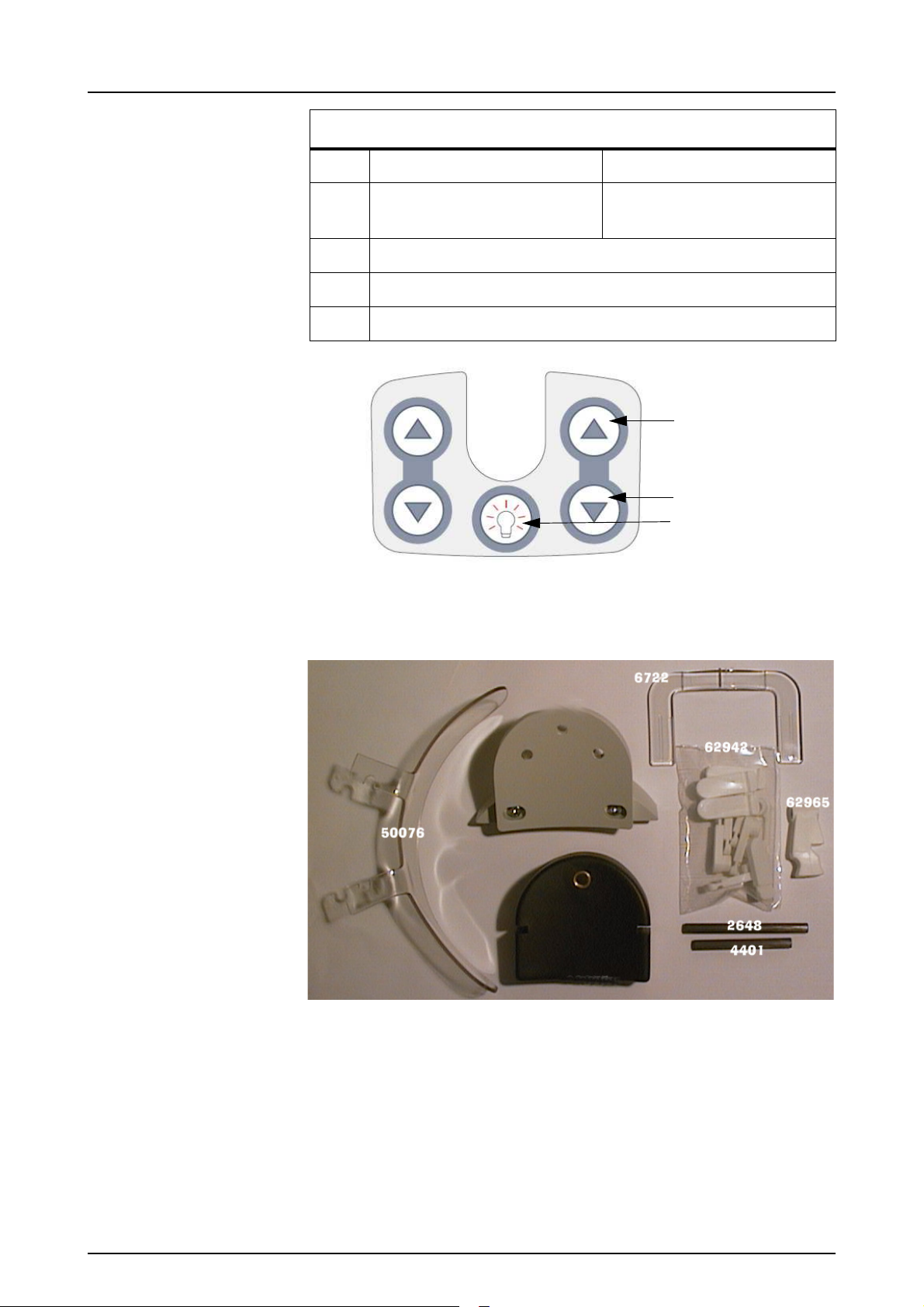
2.5 Patient positioning accessories
20 Instrumentarium Dental 5139796-100 rev 7
2 OP200 D controls and accessories
60477
Fig 2.11. TMJ patient positioning accessories
68696
200634
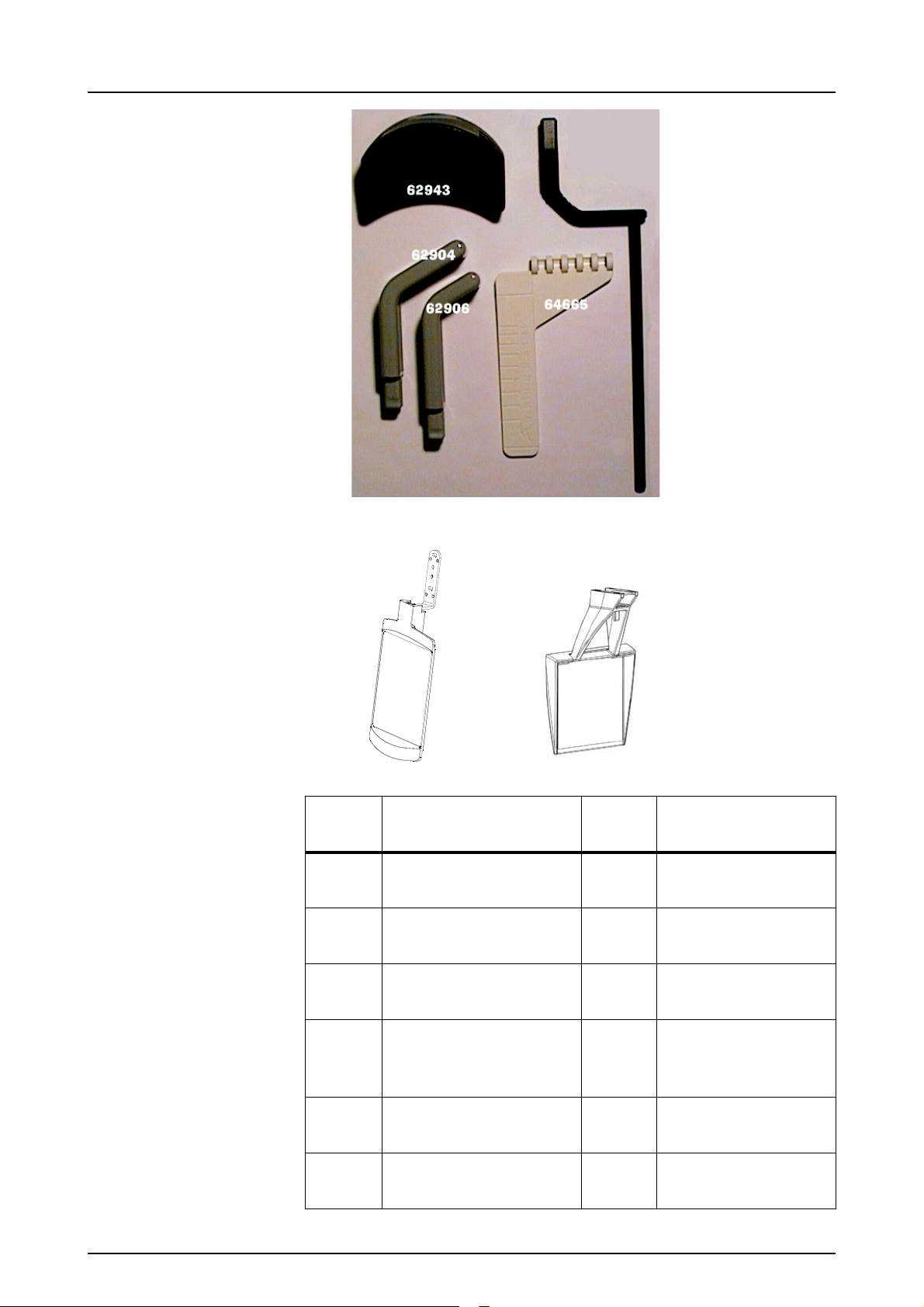
Part
code:
Part description:
Part
code:
Part description:
68758 Chin rest 62904*Nose support, long
64197 Sinus rest 62906*Nose support,
short
62942*Bite block 10 pcs 60477 TMJ pointer
62985*Bite fork, short 56 mm 64665 TMJ angle
indicator (Ortho
TMJ option)
62988*Bite fork 71 mm 62943 TMJ chin rest
(Ortho TMJ option)
62958*Bite fork, long 80 mm,
optional (not shown)
5139796-100 rev 7 Instrumentarium Dental 21
2 OP200 D controls and accessories
Part
code:
Part description:
Part
code:
Part description:
50076 Child adaptor
6722 Chin support
62965 Edentulous bite
positioner, optional
68696 Cephalostat mirror
assembly (optional
200634Carpus support
(optional)
for right hand ceph)
NOTE! The parts marked with * are autoclavable.
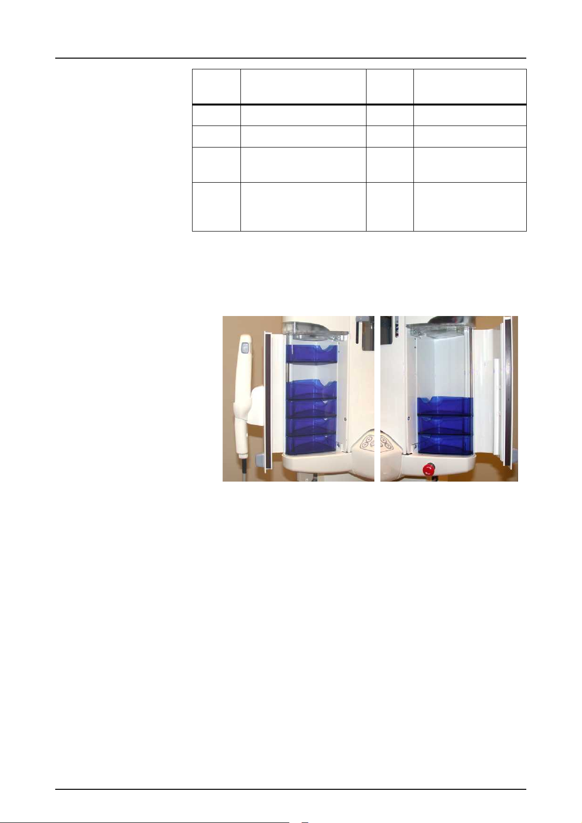
Convenient bins for small accessories and disposables are
located on the both sides of the vertical carriage.
Fig 2.12. Left and right accessory cabins
2.6 Disposables & Service accessories
The following accessories, disposables and tools are
available for the equipment:
22 Instrumentarium Dental 5139796-100 rev 7
 Loading...