

Instrumentarium Dental OP-200, OC-200 User Manual

ENGLISH
Orthopantomograph® OP200
Orthoceph® OC200
User Manual & Technical Specifications
5139539-100 rev. 2


Copyright Code: 5139539-100 rev 2 Date: 14 September 2012
Document code: D500318 rev 2
Copyright © 09/2012 by PaloDEx Group Oy. All rights
reserved.
®
Orthopantomograph
and Orthoceph® are registered trademarks of
Instrumentarium Dental. U.S. patents 6,731,717, 6,829,326 and
USRE41197. Finnish patents 114383. Windows
®
is trademark of
Microsoft Corporation in the United States of America and other
countries. Pentium
®
Iomega
Jaz® is a registered trademark of Iomega Corp.
®
is a registered trademark of Intel Corporation.
Documentation, trademark and the software are copyrighted with all
rights reserved. Under the copyright laws the documentation may not
be copied, photocopied, reproduced, translated, or reduced to any
electronic medium or machine readable form in whole or part, without
the prior written permission of Instrumentarium Dental.
The original language of this manual is English.
Instrumentarium Dental reserves the right to make changes in
specification and features shown herein, or discontinue the product
described at any time without notice or obligation. Contact your
Instrumentarium Dental representative for the most current
information.
Manufactured by Instrumentarium Dental, PaloDEx Group Oy
P.O. Box 20
FI-04301 Tuusula
FINLAND
Tel. +358 45 7882 2000
Fax. +358 45 7882 2506
For service, contact your local distributor.


Table of Contents
1 Introduction ..............................................................................................1
1.1 General ................................................................................................................. 1
1.2 Markings and graphics symbols............................................................................ 2
1.3 Type and version................................................................................................... 3
1.4 Options, accessories and manuals ....................................................................... 4
1.5 Radiation protection guidelines ............................................................................. 5
1.5.1 Protection by distance ...........................................................................................5
1.5.2 Laser lights ............................................................................................................6
1.5.3 Control from a protected area ...............................................................................6
1.5.4 Emergency Stop Switch ........................................................................................7
1.6 Manufacturer’s liability........................................................................................... 8
1.7 Disposal ................................................................................................................ 8
2 OP200 controls.........................................................................................9
2.1 Main parts ............................................................................................................. 9
2.2 OC200 ceph main parts ......................................................................................11
2.3 Control panel.......................................................................................................14
2.4 Positioning panels ............................................................................................... 17
2.5 Patient positioning accessories........................................................................... 18
2.6 Optional accessories & disposables ...................................................................19
2.7 Changing the fuses .............................................................................................20
3 Equipment preparations........................................................................ 21
3.1 Care Instructions .................................................................................................21
3.2 Cleaning recommendations ................................................................................ 21
3.2.1 Cleaning ..............................................................................................................21
3.2.2 Disinfection and sterilization................................................................................22
3.2.2.1 Autoclave ....................................................................................................... 22
3.2.2.2 Steam sterilization.......................................................................................... 22
3.2.2.3 Ethylene oxide sterilization............................................................................. 23
3.2.3 Other sterilization processes ...............................................................................23
3.2.3.1 Dry heat sterilization....................................................................................... 23
3.2.3.2 Liquid chemical sterilant gases ...................................................................... 23
3.2.3.3 Chemical sterilant gases ................................................................................ 23
3.3 Loading the panoramic cassette ......................................................................... 24
3.4 Cephalostat cassette loading .............................................................................. 26
4 Panoramic procedures .......................................................................... 29
4.1 P1: Standard panoramic exposure...................................................................... 29
4.2 P2: Pediatric panoramic exposure ......................................................................34
4.3 P3: Ortho Zone enhanced panoramic exposure ................................................. 36
4.4 P4: Orthogonal exposure ....................................................................................37
4.5 P5: Wide arch panoramic exposure .................................................................... 38
5 Special imaging procedures ................................................................. 41
5.1 P6: TMJ, Lateral projection .................................................................................41
5.2 P6: Ortho TMJ, axial corrected lateral projection (optional) ................................ 44
5.3 P7: Open - closed TMJ, lateral projection ........................................................... 47
5.4 P8: TMJ, posteroanterior projection .................................................................... 49
5.5 P9: TMJ, lateral & PA projection ......................................................................... 50
5.6 P10: Maxillary sinus view .................................................................................... 51
5139539-100 rev 2 Instrumentarium Dental i

6 Cephalometric procedures (optional) .................................................. 55
6.1 P11: Cephalo lateral projection ........................................................................... 55
6.2 P12: Cephalo posterior-anterior (PA) projection ................................................. 58
6.3 P7: Axial view of the mandible exposure ............................................................59
6.4 P5: Rewerse Towne projection exposure ........................................................... 60
6.5 P5: Waters view exposure .................................................................................. 61
6.6 P7: Carpus View exposure (optional).................................................................. 62
6.7 P13: Ortho Trans mandible exposure (optional) ................................................. 63
6.8 P14: Ortho Trans maxilla exposure (optional)..................................................... 63
7 Imaging technique ................................................................................. 65
7.1 Recommended film & screen combinations........................................................ 65
7.2 Automatic exposure control (AEC)...................................................................... 65
7.3 Exposure technique factors................................................................................. 66
7.4 Manual mode ...................................................................................................... 67
7.5 Test mode ...........................................................................................................69
7.6 Film processing ................................................................................................... 69
7.7 Measurements from the image ........................................................................... 70
8 Special features......................................................................................71
8.1 Quality assurance ............................................................................................... 71
8.2 Exposure counter ................................................................................................ 72
8.3 Preventive maintenance reminder ...................................................................... 73
8.4 Ortho ID film marking .......................................................................................... 73
8.5 OP200 CR model for computerized radiography ................................................ 73
8.6 Free selection of kV and mA ............................................................................... 74
9 Understanding the OP200 radiograph .................................................75
10 Failure diagnostics ................................................................................77
10.1 Failure messages................................................................................................ 77
10.2 kV display............................................................................................................77
10.3 mA display........................................................................................................... 77
10.4 Time display ........................................................................................................78
10.5 Resetting failure ..................................................................................................78
10.6 Multiple failure codes .......................................................................................... 79
11 Diagnosing image quality problems .................................................... 81
11.1 Patient positioning............................................................................................... 81
11.2 Film density and contrast ....................................................................................83
11.3 Artefacts ..............................................................................................................85
11.4 Unit operation......................................................................................................87
12 How to use the user programming mode .......................................... 89
12.1 General ............................................................................................................... 89
12.2 Installation & unit configuration programs .......................................................... 89
12.3 Programs affecting to image quality................................................................... 90
12.4 Other Pr programs .............................................................................................. 90
12.5 How to use the user programming mode ............................................................ 91
13 User program features...........................................................................93
13.1 PR 50 LAY: linear tomography image layer (optional) ........................................ 93
13.2 PR 51 PUS: power up setting ............................................................................. 95
ii Instrumentarium Dental 5139539-100 rev 2

13.3 PR 52 GCO and PR 52 PCO:
constant contrast & density settings.................................................................... 96
13.4 PR 53 NOR: resume normal settings................................................................ 100
13.5 PR 54 ARN: rotating unit autoreturn ................................................................. 101
13.6 PR 55 HUP: cassette holder autolift.................................................................. 101
13.7 PR 56 HLI: cassette holder vertical limit ...........................................................102
13.8 PR 57 HON: Cassette lift side........................................................................... 103
13.9 PR 58 CON: vertebrae shadow compensation ................................................. 104
13.10 PR 59 PSE: preventative maintenance reminder ............................................ 106
13.11 PR 60 BEP: panel beep................................................................................... 106
13.12 PR 61 CLC: clear exposure counter ................................................................107
13.13 PR 62 ERR: last failure code ........................................................................... 107
13.14 Pr 65 doS: dose / time display selection.......................................................... 108
13.15Pr 66 COU: Exposure counters ........................................................................ 109
14 User's statement .................................................................................. 111
15 Technical specifications......................................................................117
15.1 Electromagnetic Compatibility (EMC) tables..................................................... 123
16 Maintenance .........................................................................................127
16.1 Maintenance Schedule...................................................................................... 127
16.2 Monthly Inspection by User............................................................................... 127
16.3 Preventative Maintenance Reminder ................................................................ 127
5139539-100 rev 2 Instrumentarium Dental iii

iv Instrumentarium Dental 5139539-100 rev 2

1 Introduction
NOTE!
1.1 GENERAL
INSTRUMENTARIUM DENTAL® Orthopantomograph® OP200
panoramic unit is a software controlled diagnostic panoramic dental xray equipment for producing high quality images of dentition, TM-joints
and skull. Anatomical details will be displayed on the film magnified
nominally by 30%.
The Orthopantomograph
procedures:
• Standard panoramic exposure
• Pediatric panoramic exposure
• Wide arch panoramic exposure
• Ortho Zone enhanced panoramic exposure
• Orthogonal panoramic exposure
• TMJ, lateral projection or
• Ortho TMJ axial corrected lateral projection (optional)
• TMJ, lateral projection jaw closed and open
• TMJ, PA projection
• TMJ, lateral and PA projection
• Maxillary sinus
1 Introduction
®
OP200 can perform the following
®
Your Orthopantomograph
can be field upgraded at a later time to the Orthoceph
OP200, model OP200 OT or OP200 CR,
®
OC200 model.
With this addition, high quality cephalometric exposures can also be
made.
OP200 must be installed according to the OP200 installation &
Adjustments manual by a qualified technician. Only trained personnel
should be allowed to operate OP200.
®
In addition to the above mentioned procedures Orthoceph
OC200
can perform the following cephalometric procedures:
• Lateral view
• Postero-anterior and Antero-posterior views
• Oblique projections
• Townes, Waters, Caldwell, SMV, Carpus
®
Orthopantomograph
OP200 or Orthoceph® OC200 can also be field
upgraded to the OP/OC200 OT model. OP200 with the Ortho Trans
option can do the following linear tomographic procedures:
• Maxillary imaging in longitudinal and transversal views
• Mandible imaging in longitudinal and transversal views
Digital imaging is possible with OP200 D and OC200 D models or by
using phosphor image plates with OP200 CR, OC200 CR, OP200 OT/
CR and OC200 OT/CR models.
5139539-100 rev 2 Instrumentarium Dental 1
1 Introduction
NOTE!
CAUTION!
WARNING!
As the manufacturer we strongly recommend that you read this
manual before taking the unit into use.
1.2 MARKINGS AND GRAPHICS SYMBOLS
The following markings are used in this manual:
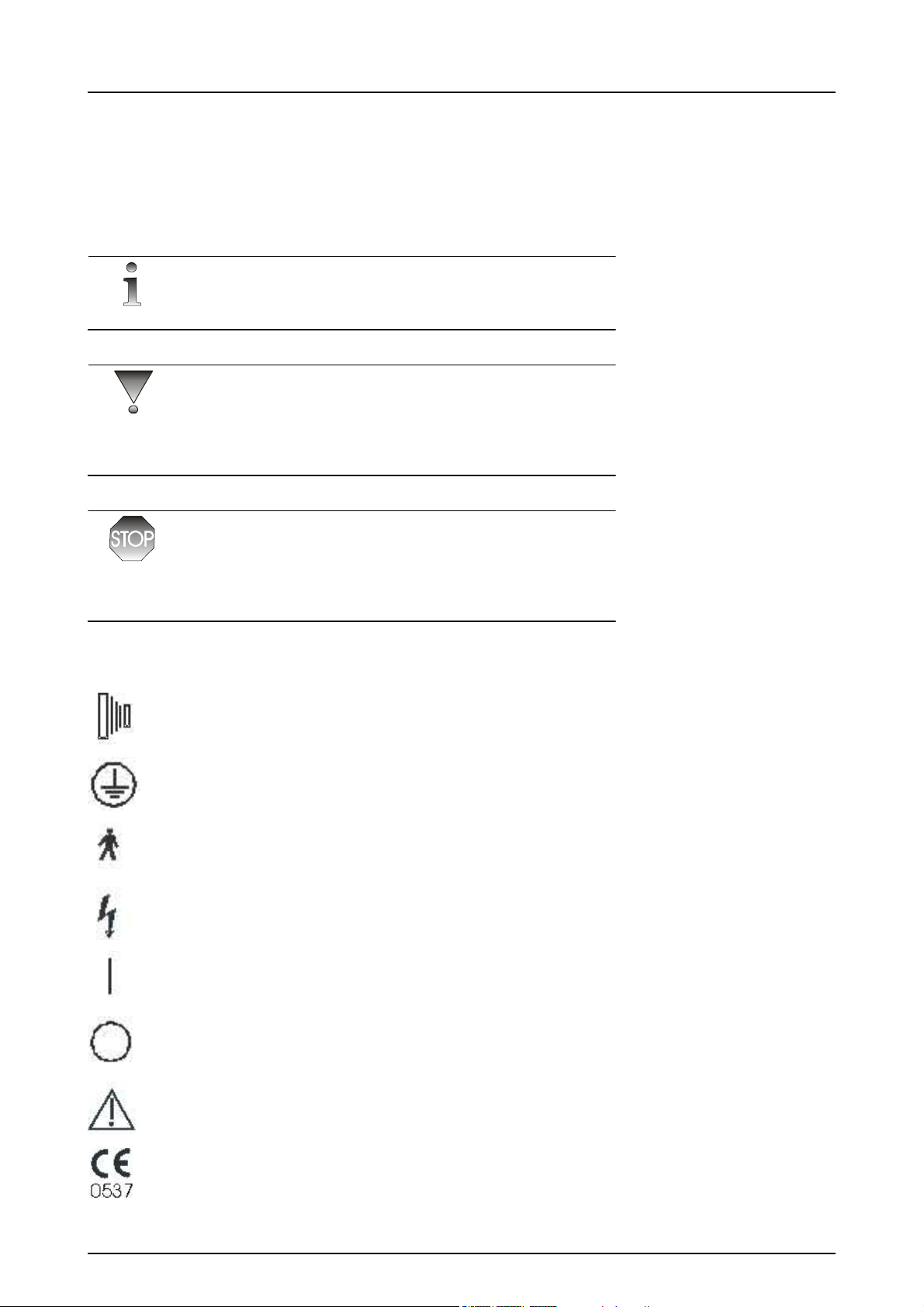
Contains useful information for the reader about the unit and its use.
Contains important instructions. If these instructions are not observed,
malfunction of the unit or damage to the unit or other property may
occur.
Contains warnings and instructions about the safety of the unit. If
these warnings are not respected, serious risks and injury may be
caused to the patient and operator.
The following symbols are used in the OP200.
Radiographic control
Protective earth (ground)
Type B equipment
Dangerous voltage
On (Power)
Off (Power)
Attention, consult accompanying documents
If the unit has CE-marking it is CE-marked according to
the Medical Device Directive 93/42/EEC.
2 Instrumentarium Dental 5139539-100 rev 2
1 Introduction
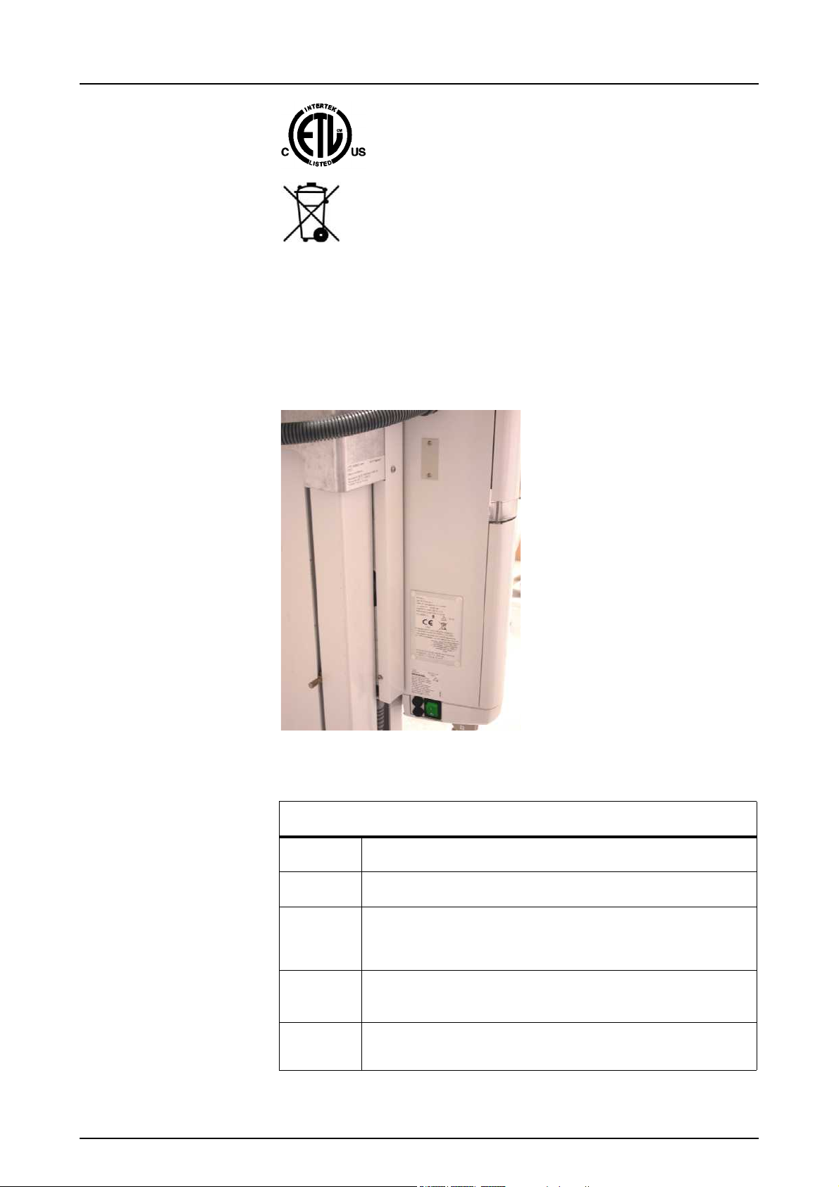
ETL symbol
This symbol indicates that the waste of electrical and
electronic equipment must not be disposed as unsorted
municipal waste and must be collected separately.
Please contact an authorized representative of the
manufacturer for information concerning the
decommissioning of your equipment.
1.3 TYPE AND VERSION
The type and version of the OP200 are defined in the main label of the
unit. The unit is class I, type B and with IP-20 protection.
Fig 1.1. Location of main label and CE mark
TYPE AND VERSION
OP200
OC200
a
short form for Orthopantomograph
®
short form for Orthoceph
OC200
type of the x-ray tube insert which is originally utilized:
®
OP200
1 = Toshiba D-051S
b
version number:
1 OP200 models starting from s/n 100 000
S
indication of a "Special" version, marked only in
products which have a non-standard modification
5139539-100 rev 2 Instrumentarium Dental 3

1 Introduction
WARNING!
NOTE!
CAUTION!
For example, OP200-1-1 is:
®
(OP200) Orthopantomograph
OP200
(-1) with Toshiba D-051S tube
(-1) first version of OP200.
1.4 OPTIONS, ACCESSORIES AND MANUALS
The options are listed in the appendices. The accessories are listed in
sections 2.5 and 2.6. All standard items and approved accessories are
suitable for use within the patient environment.
This product itself complies IEC601-1-1 medical safety standard but in
order to the system incorporating also a PC to comply the standard,
EITHER the PC has to be a medical PC OR the PC has to be located
over 1,5 meters apart from the OP/OC200 unit. The installer and the
user of the system shall confirm that at least one of the above
requirements is fulfilled. A PC is a medical one if it complies IEC 6011standard and that is indicated in the accompanying documents of the
PC.
To maintain safe and correct functioning of OP200, only the approved
accessories may be used.
Use of controls or adjustments or performance of procedures other
than those specified herein may result in hazardous radiation
exposure.
Following manuals and documents are shipped with the OP200:
• OP200 / OC200 User Manual & Technical Specifications
• OP200 / OC200 Installation & Adjustments Manual
These manuals and future updates are available on request from the
manufacturer.
4 Instrumentarium Dental 5139539-100 rev 2

1 Introduction
NOTE!
WARNING!
1.5 RADIATION PROTECTION GUIDELINES
X-ray equipment may cause injury if used improperly. The instructions
contained in this manual must be read and followed when operating
the Orthopantomograph
pertaining to radiation safety must be observed.
For USA: Many provisions of these regulations are based on
recommendations of the National Council on Radiation Protection and
Measurements. Recommendations for dental x-ray protection are
published in NCRP Report #35 available from NCRP Publications,
7910 Woodmont Avenue, Suite 1016, Bethesda, MD 20814.
Personal radiation monitoring and protective devices are available and
recommended for staff members. It is also recommended to provide
the patient with a protective apron. Consult the physician before taking
images of pregnant patients.
®
OP200. All government and local regulations
Orthopantomograph® OP200 must not be used in rooms where an
explosion hazard exists. Equipment not suitable for use in the
presence of flammable mixtures.
OP200 with radiation protection in accordance with IEC601-1-3:1994.
1.5.1 Protection by distance
In all examinations the user of the x-ray equipment should wear
protective clothing. The operator does not need to be close to the
patient during normal use. The protection against stray radiation can
be achieved by using the hand switch not less than 2 m (7 ft.) from the
focal spot and the x-ray beam. Operator should maintain visible
contact with the patient and technique factors. This allows immediate
termination of radiation by the release of the exposure button in the
event of a malfunction or disturbance.
Fig 1.2. Caution information on Control panel
5139539-100 rev 2 Instrumentarium Dental 5
1 Introduction
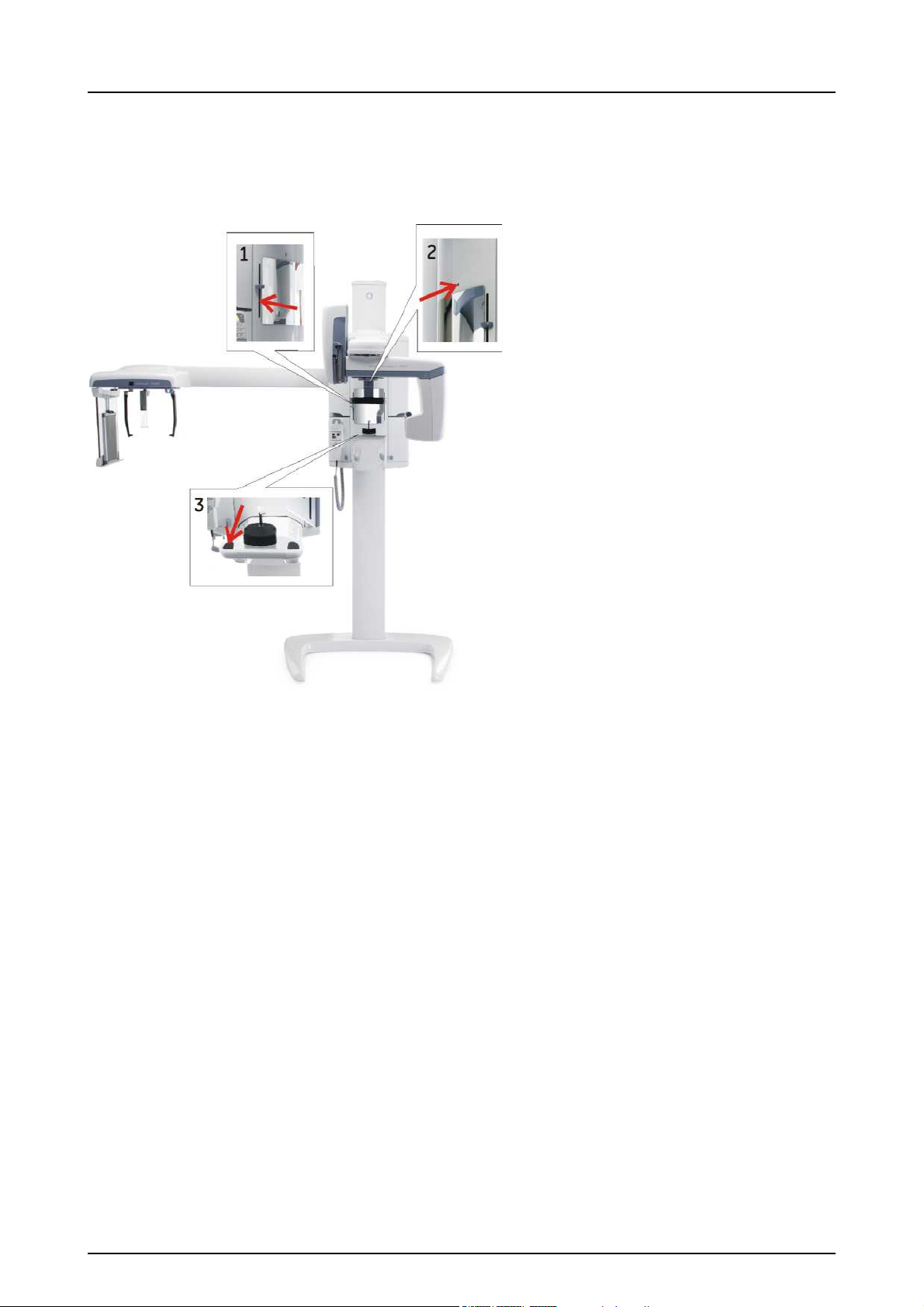
1.5.2 Laser lights
1 FH-light
2 Mid-Sagittal light
3 Layer light
Fig 1.3. Laser light (CLASS 1 LASER PRODUCT). Max output 100µW.
1.5.3 Control from a protected area
The operator does not need to be close to the patient during normal
use. Control panel hand switch or optional remote hand switch can be
used from an area protected from the x-ray beam. The fully extended
spiral cable length of the control panel hand switch is approx. 4 m / 13
ft. The cable length of the remote hand switch (part #69961) is
approximately
10 m / 32 ft.
6 Instrumentarium Dental 5139539-100 rev 2

1.5.4 Emergency Stop Switch
1 Introduction
In case of malfunction of the exposure button release or other
protective devices of the unit, an emergency stop switch is provided
on the right side of the unit so that the patient can reach it. If the
emergency stop switch is pressed during the exposure, the exposure
is terminated immediately and the x-ray unit is completely stopped.
The exposure interrupted by emergency stop switch, cannot be
continued later, but has to be retaken from the beginning.
5139539-100 rev 2 Instrumentarium Dental 7

1 Introduction
1.6 MANUFACTURER’S LIABILITY
As a manufacturer we can only assume liability of safe and reliable
operation of this unit when
• OP200 unit installation was performed according to the OP200
Installation & Adjustments Manual and
• OP200 Unit is used according to the OP200 User Manual
• Maintenance and repairs are performed by a qualified
Orthopantomograph
• Original or authorized spare parts are used
In order to quarantee maximal image quality for entire life time of this
high performance imaging system, we suggest that a special image
quality assurance procedure (* and test object designed for image
quality assurance purposes is used (code 68795). Also we
recommend qualified serviceman to check the unit to be in its original
condition regarding electrical, radiation and mechanical safety
according to our maintenance program described in more details in
maintenance manual (code 61049) every year or after 2000 images.
For more information please contact your local dealer.
®
OP200 Dealer and
*) According EN61223-3-4 and DIN 6868-151
If service on the unit is performed, a work order describing the type
and extent of repair must be provided by the service technician. This
must contain information of changes of nominal data or work range
performed. The work order must furthermore indicate the date of
repair, the name of the company concerned and a valid signature.
User should keep this work order for future references.
1.7 DISPOSAL
Follow the local regulations on disposal of waste parts. OP200 has at
least the following parts that should be regarded as non-environmental
friendly waste products:
– X-ray source assembly
– All electronic circuits
– Column counter weight (Pb)
8 Instrumentarium Dental 5139539-100 rev 2
2 OP200 controls
1
2
3
4
5
6
7
8
9
10
11
12
13
14
Optional Cephalostat
15
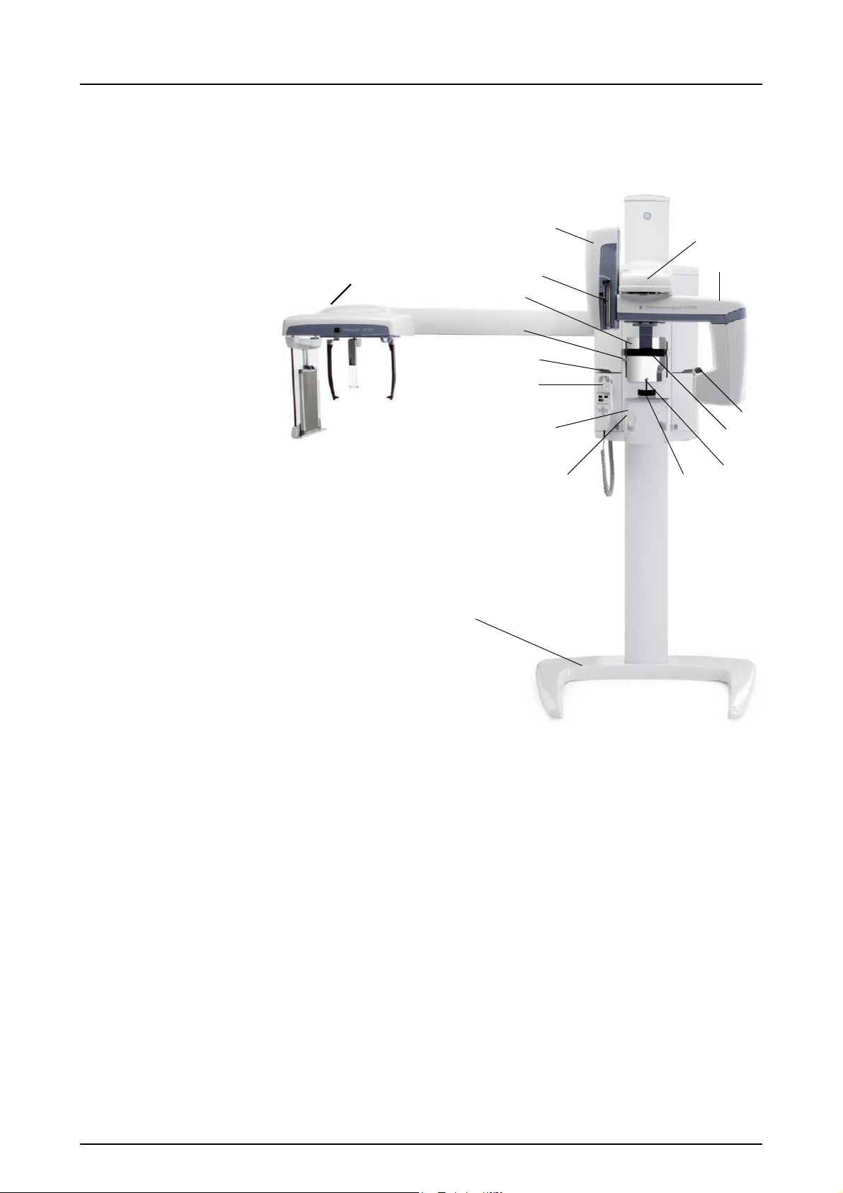
2.1 MAIN PARTS
2 OP200 controls
1 Cassette holder
2 Main support
3 Film cassette
4 Rotating unit
5 Head and Temple support
6 Primary collimator
7 Bite fork with rod
8Chin rest
9 Handles
10 Patient positioning panel
11 Control panel
12 Exposure indicator lights
13 FH light height adjustment
14 Mirror
15 Base plate (optional)
5139539-100 rev 2 Instrumentarium Dental 9
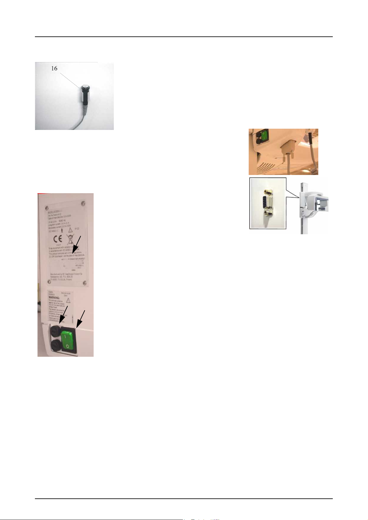
2 OP200 controls
24
25
22
21
23
16 Exposure Button with cable and holder (optional in some
markets)
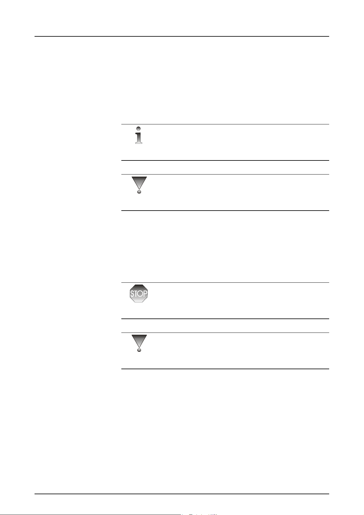
21) Main label
22) Power ON / OFF switch with an indicator
23) Main fuses with label
24) Connector for Control panel
25) Connector for Ortho ID (optional)
Fig 2.1. Unit main label and Power switch
10 Instrumentarium Dental 5139539-100 rev 2

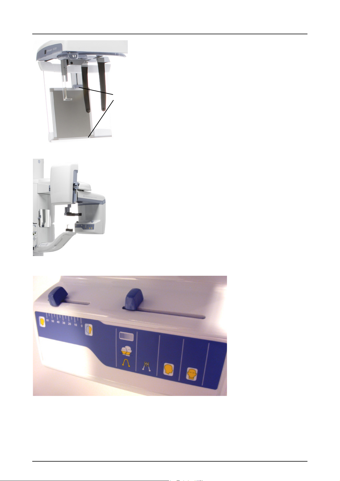
2.2 OC200 CEPH MAIN PARTS
Fig 2.3. Head positioner, ear holde
cassette holder
10
6
1
2
3
4
5
7
8
11
9
Fig 2.4. Lock for axial rotation
Fig 2.5. Soft tissue scale display
Fig 2.2. OC200 LL: Cephalostat mounted on the left side
2 OP200 controls
Cephalostat arm
1 Cephalostat head
2 Cassette holder
3 Cassette retainer
4 Film cassette sizes:
18 x 24 cm and
24 x 30 cm or
8” x 10” and
10” x 12”
5 Guides for optional grid
6 Lock for axial rotation
(see Fig 2.5)
7Ear rods
8 Nasion support
9 Soft tissue scale display
10 Magnification scale
11 Ear holder brake
5139539-100 rev 2 Instrumentarium Dental 11
2 OP200 controls
4
5
1
3
4
5
6
7
2
8
Fig 2.6. Cassette (4) and grooves (5) for optional grid
Fig 2.7. Panoramic cassette holder lifted to allow cephalostat procedure
Fig 2.8. Tubehead
12 Instrumentarium Dental 5139539-100 rev 2

2 OP200 controls
NOTE!
NOTE!
NOTE!
Tube head
1 Soft tissue filter scale & slider
2 Quality Assurance collimator "QA"
3 Pediatric collimator
4 Panoramic collimator "PAN"
5 Ortho Trans Collimator
6 Cephalometric collimator alternatives: Lateral view: Europe 18 x
24 cm AH,
18 x 24 cm AV, other markets 8” x 10” AV, 10” x 8” AH, 10” x 12”
AV
7 Cephalometric collimator: Symmetrical view: Europe 18 x 24 cm
SV, other markets 8” x 10” SV
8 Collimator selection lever
5-7: Cassette orientation markings:
AV = Asymmetric vertical,
AH = Asymmetric horizontal,
SV = Symmetrical vertical (for facial / PA views).
Pediatric collimator is available when the lever on the PAN position is
lifted up for one step. QA collimator is available when the lever on the
PAN position is lifted up for two steps.
The collimator selection and film sizes are usually connected to the
used systems in the counter so that you can select the cm or inch
sizes, but not mixed.
5139539-100 rev 2 Instrumentarium Dental 13
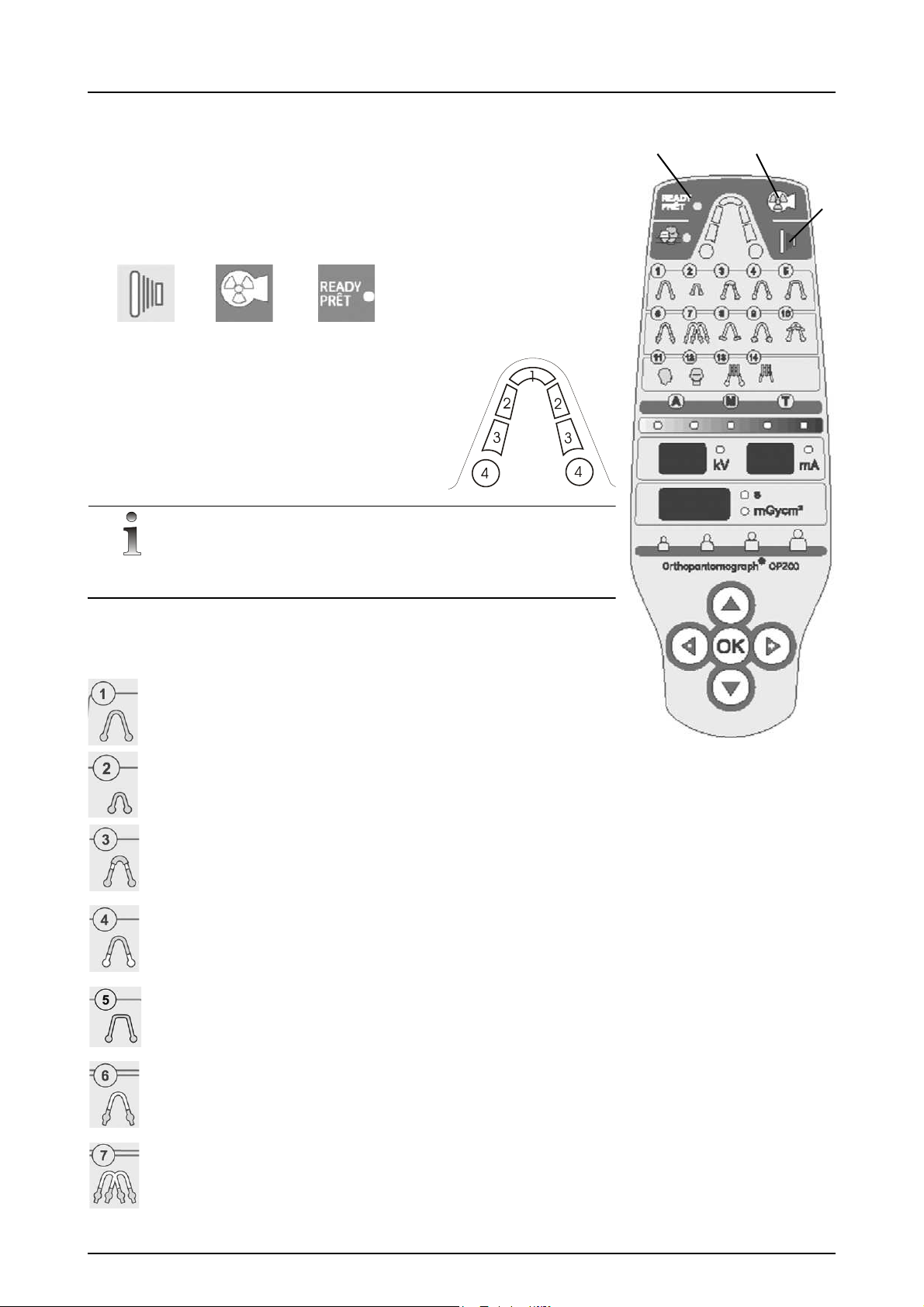
2 OP200 controls
NOTE!
32
1
1
3
2
2.3 CONTROL PANEL
Exposure Control
1 Exposure Button
2 Exposure Indicator Light
3 "Ready" Indicator Light
Sections
1 Anterior
2Premolar
3Molar
4Jaw joint
Sections 2 and 3 are combined as one section in panoramic
programs.
Imaging Procedures P1-P14 with Indicator lights
Standard Panoramic (P1)
Pediatric Panoramic (P2)
Ortho Zone enhanced panoramic
exposure (P3)
Orthogonal exposure (P4)
Wide arch panoramic exposure
(P5)
TMJ, lateral projection (P6) or
Ortho TMJ, axial corrected lateral
projection (P6 optional)
Open-closed TMJ, lateral
projection on one film (P7)
14 Instrumentarium Dental 5139539-100 rev 2

2 OP200 controls
TMJ, posterior-anterior projection
(P8)
TMJ lateral and TMJ PA projection
on one film (P9)
Maxillary sinus view (P10)
Cephalo lateral projection (P11)
Cephalo PA projection and other
special projections (P12)
Ortho Trans mandible (P13
optional)
Ortho Trans maxilla (P14 optional)
Exposure Modes with Indicator lights
Automatic Exposure Control
Test Mode
Manual Exposure Control
Automatic Exposure Density Scale (nine steps)
Default
One and half steps lighter
Half step darker
Two steps darker
5139539-100 rev 2 Instrumentarium Dental 15
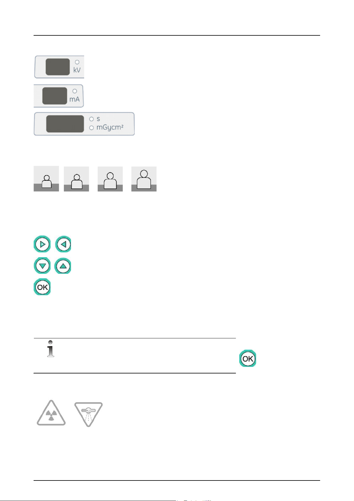
2 OP200 controls
NOTE!
Child
Juvenile
Adult
Large
adult
Control panel displays
kV display
mA display
Exposure time display /
Exposure counter value
display
Icons for Pre-programmed Technique Factors with Indicator
lights
Function Selection buttons
Move the flashing indicator left or right
Decrease or increase the value on display
Move the flashing indicator up or down to the
next selection row
P1-P12: Show Exposure counter value or
reset user error (Ch)
In the programming mode:
• Enter & Exit Program Mode
• Accept the displayed choice
OK button has special functions in the user and service programming
mode. See User Program Chapter in the User Manual for details.
Radiation warning
16 Instrumentarium Dental 5139539-100 rev 2

2.4 POSITIONING PANELS
28
25
24
23 22
21
20
20
26
27
Fig 2.9. Positioning panel, right side
(on left side just the buttons 25 and 26 are flipped)
Positioning Panel button meaning in each mode
2 OP200 controls
Key Panoramic
(P1-P5)
Cephalostat
(P11-P12)
TMJ
(P6-P9)
20 Carriage vertical movement up / down
21 moves the
image layer
3 mm
anterior
moves
image
layer
anterior
during
exposure
22 normal
occlusion /
reset to
middle
reset position
23 moves the
image layer
3 mm
posterior
moves
image
layer
posterior
during
exposure
24 Positioning
Positioning lights on / off
lights on / off
Maxillary Sinus
(P10)
moves the image
layer 10 mm
anterior from
nominal position
during exposure
nominal position
moves the image
layer 10 mm
posterior from
nominal position
during exposure
25 Rotating unit movement: Start position
26 Cassette holder down
27 Cassette holder up
28 Rotating unit movement: Patient positioning
5139539-100 rev 2 Instrumentarium Dental 17
2 OP200 controls
50076
62895
62875
6722
62942 62965
62985
62988
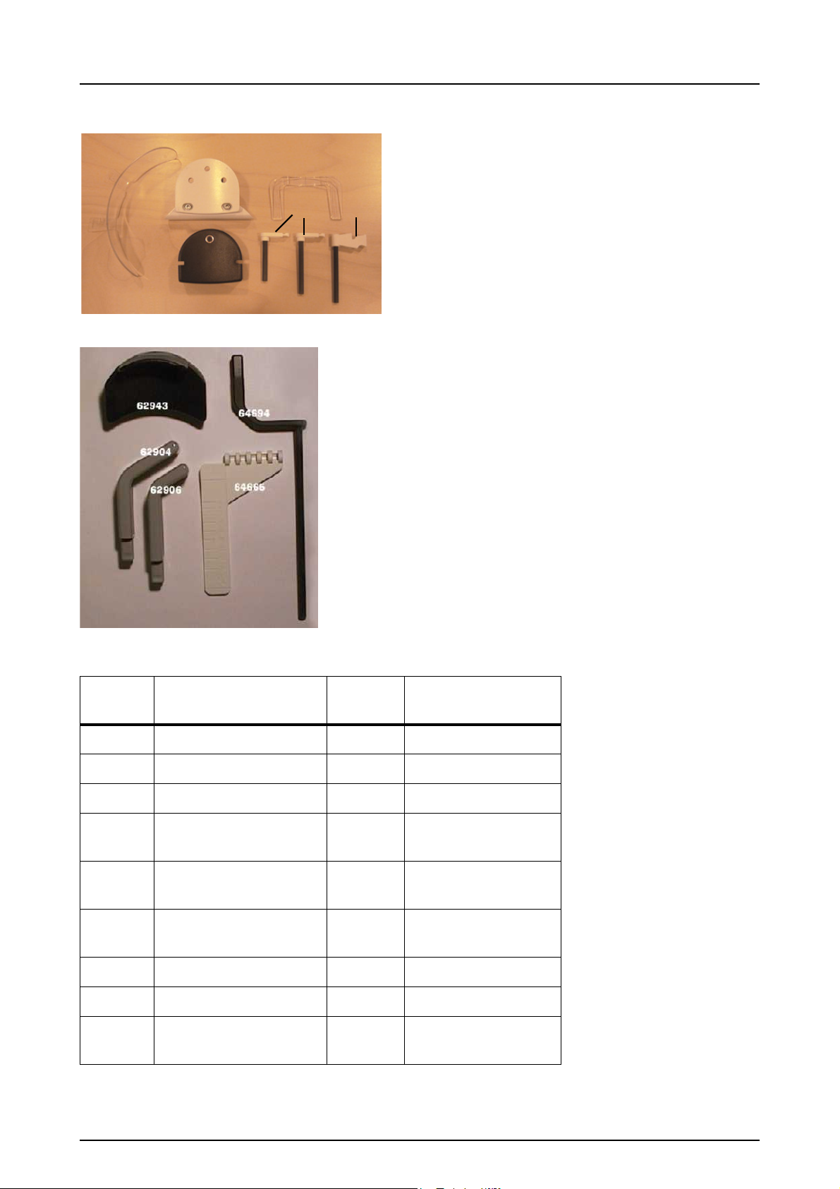
2.5 PATIENT POSITIONING ACCESSORIES
Fig 2.10. Panoramic patient positioning accessories
Fig 2.11. TMJ patient positioning accessories
Part
code:
Part description: Part
code:
Part description:
62875 Chin rest 62904* Nose support, long
62895 Sinus rest 62906* Nose support, short
62942* Bite block 10 pcs 60477 TMJ pointer
62985* Bite fork, short 56 mm 64665 TMJ angle indicator
(Ortho TMJ option)
62988* Bite fork 71 mm 62943 TMJ chin rest
(Ortho TMJ option)
62958* Bite fork, long 80 mm,
optional (not shown)
64694 TMJ pointer (for
Ortho Trans units)
50076 Child adaptor
6722 Chin support
62965 Edentulous bite
positioned, optional
18 Instrumentarium Dental 5139539-100 rev 2
2 OP200 controls
NOTE!
8915
7453
6644
7451
7452
The parts marked with * are autoclavable.
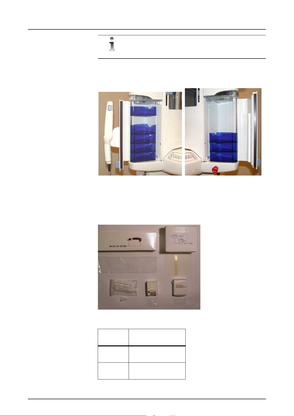
Convenient bins for small accessories and disposables are located on
the both sides of the vertical carriage.
Fig 2.12. Left and right cabins.
2.6 OPTIONAL ACCESSORIES & DISPOSABLES
The following optional accessories, disposables and tools are
available for the equipment:
Fig 2.13. Consumer accessories
Part
Part description:
code:
6644 Bite fork coat,
200 pcs
7451 Chin rest coat,
200 pcs
5139539-100 rev 2 Instrumentarium Dental 19
2 OP200 controls
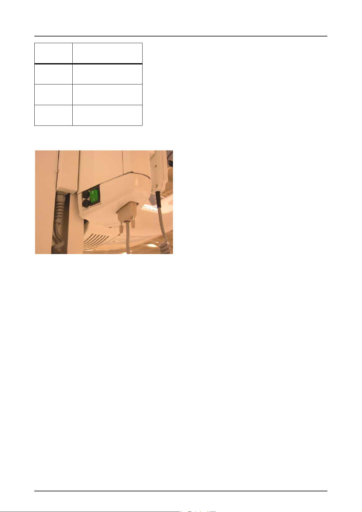
Part
code:
7452 Temple support coat,
7453 Nose support coat,
8915 Ear holder coat,
Part description:
200 pcs
200 pcs
20 pcs
2.7 CHANGING THE FUSES
Push inward on the fuse base and twist it counter-clockwise with a
screwdriwer. The fuse with the base will come out.
Remove the fuse from the base and replace it with the new one.
Repeat this with each blown fuse.
Fasten both fuses by pushing the base in and twisting it clockwise with
a screwdriver.
Use only appropriate fuses:
326 Littelfuse 10A (slow blow) 230 VAC line voltage
MDA-15 Cooper Bussman 15A (time delay) 115 VAC line voltage
20 Instrumentarium Dental 5139539-100 rev 2
3 Equipment preparations
NOTE!
CAUTION!
WARNING!
CAUTION!
3.1 CARE INSTRUCTIONS
X-ray devices are sophisticated electronic products including
advanced technologies. As such, they have to be handled with a high
degree of care. This document gives the care instructions applicable
to the Orthopantomograph
It is strictly mandatory to follow these Care Instructions in order to not
void the warranty of the product.
As a standard recommendation, clean the unit regularly using nonagressive, mild, commercially available cleaning agents.
®
panoramic and cephalostat units.
3 Equipment preparations
3.2 CLEANING RECOMMENDATIONS
The unit should be cleaned after every usage between the patients.
Items and surfaces that are not given special instructions for cleaning,
disinfecting and sterilizing, can be cleaned with soft cloth moistured
with disinfective after every usage.
Always disconnect OP200 from mains or switch off the power prior to
cleaning or disinfecting the unit.
Do not allow water or other cleaning liquids to enter the unit interior
since these may cause short-circuits or corrosion.
3.2.1 Cleaning
The purpose of cleaning and rinsing is to remove all adherent visible
soil (eg. blood, protein substances and other debris), to reduce the
number of particulate and micro-organisms, and to reduce the amount
of pyrogenic and antigenic material.
Use a cloth moistened in cool-to-lukewarm, soapy water to clean the
unit, and prevent coagulation and thus faciliate the removal of protein
substances. Then wipe with a cloth moistened in clear water. Mild
detergent solution can be used. Use cleaners or solvents, which are
listed as allowed cleaning agents below. If you are uncertain of the
nature of cleaning agent, do not use it.
5139539-100 rev 2 Instrumentarium Dental 21

3 Equipment preparations
NOTE!
WARNING!
Examples of cleaning agents that are allowed or prohibited when
cleaning the unit panels:
Allowed: Methanol (metyl alcohol), Soap, Isopropyl alcohol, distilled
water.
Not allowed: Bentzene, Chlorine bentzene, Acetone, Acetic ether,
agents containing phenol, paracetic acid, peroxide and other oxygencleaving agents, sodium hypochlorite and iodine-cleaving agents.
3.2.2 Disinfection and sterilization
The disinfection and sterilization concerns the parts of the equipment
like bite block, chin support and accessories. Wipe manually with
clean cloth moistured in disinfectant solution. Never use corrosive or
solvent disinfectants. All items and surfaces should be dried before
next usage.
Wear gloves and other protective equipment during decontamination
process.
Do not use any disinfecting sprays since the vapor could ignite
causing injury.
Disinfecting techniques for both the unit and the room must comply
with all laws and regulations that have jurisdiction of law within the
jurisdiction on which the unit is.
3.2.2.1 Autoclave
Some removable parts in touch with the patient are sterilizable in
autoclave. Such parts are:
Bite forks (62985, 62988, 62958), Bite block (62942) and Nose
supports (62906, 62904).
If autoclaving is performed for these items, disinfection by immersing
in disinfectant solution for 10 minutes is not needed.
3.2.2.2 Steam sterilization
Recommended parameters for sterilizable parts are:
Gravity-displacement steam sterilization
"Flash" sterilization:
Temperature: 270 F (132°C)
Exposure time: 3 minutes
Prevacuum steam sterilization
"Flash" sterilization:
22 Instrumentarium Dental 5139539-100 rev 2
 Loading...