

Instrumentarium Dental OP-200 Troubleshooting manual
Orthopantomograph
®
Orthoceph
Troubleshooting Manual
OC200 & OC200 D
®
OP200 & OP200 D
Reviewed: Rintamäki Markus 2008-05-26 15:43
Approved: Äärynen Teemu 2008-06-04 17:35
See PDM system to determine the status of this document. Printed out: 2015-04-10 11:48:23
Copyright © 2008 by PaloDEx Group Oy. All rights reserved.
200214 rev 3
D500211, 3
Approved

Reviewed: Rintamäki Markus 2008-05-26 15:43
Approved: Äärynen Teemu 2008-06-04 17:35
See PDM system to determine the status of this document. Printed out: 2015-04-10 11:48:23
Copyright © 2008 by PaloDEx Group Oy. All rights reserved.
D500211, 3
Approved

Copyright Code: 200214 rev 3 Date: 22 May 2008
Document code: D500211 rev 3
Copyright © 05/2008 by PaloDEx Group Oy.
All rights reserved.
Orthopantomograph® and Orthoceph® are registered trademarks
of Instrumentarium Dental. U.S. patents 4,641,336; 5,016,264;
5,425,065, 5,444,754, 6,731,717 and 6,829,326. German patent
4,344,745. Finnish patents 112594 and 114383. Windows
trademark of Microsoft Corporation in the United States of
America and other countries. Pentium
of Intel Corporation. Iomega
®
Jaz® is a registered trademark of
Iomega Corp.
Documentation, trademark and the software are copyrighted
with all rights reserved. Under the copyright laws the
documentation may not be copied, photocopied, reproduced,
translated, or reduced to any electronic medium or machine
readable form in whole or part, without the prior written
permission of Instrumentarium Dental .
®
is a registered trademark
®
is
The original language of this manual is English.
Instrumentarium Dental reserves the right to make changes in
specification and features shown herein, or discontinue the
product described at any time without notice or obligation.
Contact your Instrumentarium Dent al repr esent ativ e fo r the most
current information.
Manufactured by Instrumentarium Dental
Nahkelantie 160 (P.O. Box 20)
FI-04300 Tuusula
FINLAND
Tel. +358 45 7882 2000
Fax. +358 9 851 4048
For service, contact your local distributor.
Reviewed: Rintamäki Markus 2008-05-26 15:43
Approved: Äärynen Teemu 2008-06-04 17:35
See PDM system to determine the status of this document. Printed out: 2015-04-10 11:48:23
Copyright © 2008 by PaloDEx Group Oy. All rights reserved.
D500211, 3
Approved

Reviewed: Rintamäki Markus 2008-05-26 15:43
Approved: Äärynen Teemu 2008-06-04 17:35
See PDM system to determine the status of this document. Printed out: 2015-04-10 11:48:23
Copyright © 2008 by PaloDEx Group Oy. All rights reserved.
D500211, 3
Approved

Table of Contents
1 General trouble shooting............................................................................................1
1.1 OP200 Does not operate at all..............................................................................1
1.2 No exposure, no error message, but movements ok............................................1
1.3 Exposure ok, but no movements...........................................................................2
1.4 OP200 Malfunctions, but no error message..........................................................3
1.5 Positioning lights do not operate...........................................................................3
1.6 Cephalostat programs cannot be selected............................................................4
1.7 DAP reading in Control panel is incorrect.............................................................4
1.8 Ceph lateral program can’t be selected................................................................4
1.9 Automatic collimator not detected (digital unit) ....................................................5
1.10 Problem with film image quality.............................................................................5
1.11 Problems with digital image quality.......................................................................7
1.11.1 Image is grainy or noisy.............................................................................7
1.11.2 Image is striped..........................................................................................8
1.11.3 Image is too dark / light..............................................................................9
2 Electric trouble shooting..........................................................................................11
2.1 Microswitches and position indicators.................................................................11
2.2 General, failure messages..................................................................................1 1
2.3 Film unit failure messages ..................................................................................14
2.3.1 Ch 1 CAS.................................................................................................14
2.3.2 Ch 2 CAS (film unit).................................................................................16
2.3.3 Ch 3 COL (film unit) ..............................................................................19
2.3.4 Ch 4 COL..............................................................................................22
2.3.5 Sy 25 AEC..............................................................................................24
2.3.6 Sy 28 PoC..............................................................................................25
2.3.6.1 Cassette movement, principle.................................... .... ...........26
2.3.7 Sy 30 PoH..............................................................................................27
2.3.7.1 Rack movement, principle.........................................................29
2.4 Digital unit failure messages...............................................................................29
2.4.1 Ch 1 PC....................................................................................................29
2.4.1.1 Fiber test....................................................................................32
2.4.2 Ch 2 PAc (digital unit) ..................... .... ..... ..... ............................ .... ..... ......33
2.4.3 Ch 2 CEc (digital unit)..............................................................................33
2.4.4 Ch 3 COL (digi).....................................................................................35
2.4.5 Ch 15 bPL................................................................................................37
2.4.6 Ch 17 HSP...............................................................................................38
2.4.7 Sy 25 AEC (digital unit)..........................................................................38
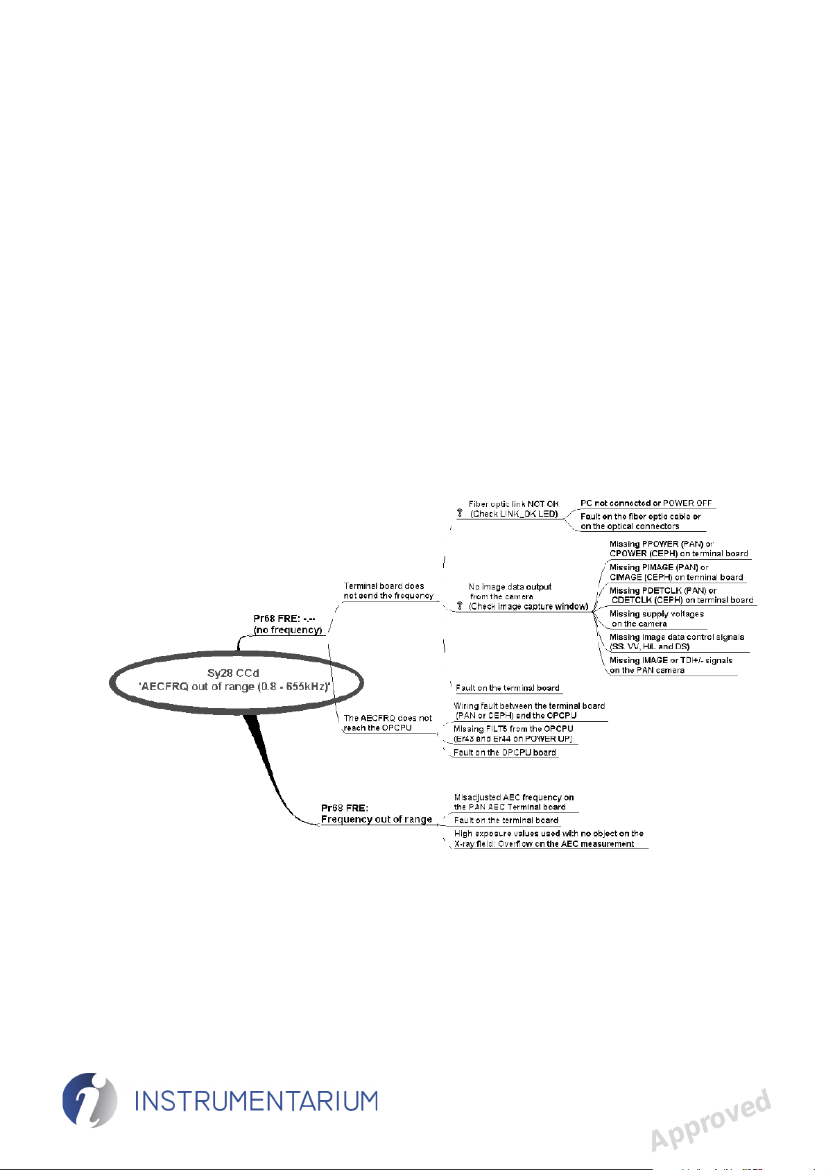
2.4.8 Sy 28 CCd................................................................................................40
2.4.8.1 AEC Frequency generation, block diagram......................... ..... .44
2.4.9 Sy 30 PoC................................................................................................45
2.4.10 Sy 38 COL................................................................................................47
2.4.11 Sy 32 PoA................................................................................................49
2.5 Digital image chain trouble shooting...................................................................52
2.6 Digital image faults ..............................................................................................55
2.6.1 Detector fail..............................................................................................55
2.6.2 Data bits missing.................................................... ..... .... .........................56
2.6.3 PC............................................................................................................58
200214 rev 3 Instrumentarium Dental i
Reviewed: Rintamäki Markus 2008-05-26 15:43
Approved: Äärynen Teemu 2008-06-04 17:35
See PDM system to determine the status of this document. Printed out: 2015-04-10 11:48:23
Copyright © 2008 by PaloDEx Group Oy. All rights reserved.
D500211, 3
Approved

2.6.4 Poor beam alignment............................................. ............................ ..... .61
2.7 Common errors...................................................................................................63
2.7.1 Ch 5 *** .................................................................................................63
2.7.2 Ch 6 POS...............................................................................................63
2.7.3 Ch 7 *** .................................................................................................66
2.7.4 Ch 8 PSE ..............................................................................................67
2.7.5 Ch 9 rEo................................................................................................68
2.7.6 Ch 11 PAr.................................................................................................69
2.7.7 Ch 12 dCC ...............................................................................................70
2.7.8 Ch 16 StP.................................................................................................71
2.7.9 Sy 20 ***...................................................................................................71
2.7.10 Sy 21 HHo................................................................................................73
2.7.11 Sy 22 Arc..................................................................................................74
2.7.12 Sy 23 Inu..................................................................................................76
2.7.13 Sy 24 FIL..................................................................................................77
2.7.14 Sy 26 EEP................................................................................................78
2.7.15 Sy 27 Por .................................................................................................78
2.7.15.1 Rotation movement, principle...................................................80
2.7.16 Sy 29 PoL.................................................................................................82
2.7.16.1Linear movement, principle........................................................83
2.7.17 Sy 31 PoU................................................................................................84
2.7.17.1Carriage movement, principle....................................................85
2.7.18 Er 40 Core Module...................................................................................86
2.7.19 Er 41 Core Module...................................................................................87
2.7.20 Er 42 Core Module...................................................................................88
2.7.21 Er 43 *** ...................................................................................................88
2.7.21.1Filament Control Board self check principle..............................89
2.7.22 Er 44 FIL ..................................................................................................90
2.7.23 Er 45 InP..................................................................................................9 1
2.7.24 Er 46 PAy.................................................................................................93
2.8 Indicators and test points....................................................................................93
2.8.1 Led-indicators...........................................................................................93
2.8.2 Test points................................................................................................94
3 Appendix A: Optical Link Test..................................................................................95
3.1 PCI board driver check........................................................................................96
3.2 PCI board, PAN-AEC Term inal bo ard an d Ceph Term inal bo ard l eds status che ck
96
3.2.1 Standard PCI board.................................................................................96
3.2.2 Low profile PCI board
(combined supply voltage led) .................................................................97
3.2.3 PCI board (60187) leds status check.......................................................97
3.2.4 PAN AEC Terminal board (60247) leds status check..............................97
3.2.5 Ceph t erminal board (60191) leds status check
(optional)..................................................................................................98
3.3 PCI Board Fiber Test ..........................................................................................98
3.4 PAN AEC Terminal Board (60247) Fiber Test..................................................100
3.5 Ceph Terminal Board (60191) optical loop test (optional).................................102
ii Instrumentarium Dental 200214 rev 3
Reviewed: Rintamäki Markus 2008-05-26 15:43
Approved: Äärynen Teemu 2008-06-04 17:35
See PDM system to determine the status of this document. Printed out: 2015-04-10 11:48:23
Copyright © 2008 by PaloDEx Group Oy. All rights reserved.
D500211, 3
Approved

1 General trouble shooting
Trouble shooting guides listed in this manual are for
solving imaging problems. In case there is no solution
found, contact the technical customer service of the
manufacturer.
Parts are identified in the wiring diagram with letter(s)
followed by number eg. cable or capacitor (C), coil/inductor
(L), fuse (F), lamp (LA), motor (M ), switch (S), coile d cable
(SC), and connector (X).
1.1 OP200 Does not operate at all
Possible causes: Check that:
1 General trouble shooting
No power or
OP200 is not
receiving power.
Power switch
turned off.
Wrong mains
voltage setting.
Problem with
secondary
voltages.
Emergency stop
switch is
pressed.
Site’s circuit breakers are ok
Mains cables are connected inside the
OP200 and the unit is properly connected
to the mains voltage.
Mains fuses are ok and have the correct
rating.
The power on/off switch is at I position.
Green indicator under the carriage should
be lit.
OP200 mains voltage setting on the
Power Supply Board matches the power
line.
Fuses of secondary voltages are ok and
that individual circuit boards are receiving
the power (green LED’s).
Make sure the problem, why the switch
was pressed, is solved before relea sing
the switch and turning the unit on.
1.2 No exposure, no error message, but
movements ok
Possible causes: Check
Remote exposure
button does not
operate.
200214 rev 3 Instrumentarium Dental 1
Reviewed: Rintamäki Markus 2008-05-26 15:43
Approved: Äärynen Teemu 2008-06-04 17:35
See PDM system to determine the status of this document. Printed out: 2015-04-10 11:48:23
Copyright © 2008 by PaloDEx Group Oy. All rights reserved.
Signal EXPSW switch and its
wiring. Use Sr 74 IOC.
Approved
D500211, 3

1 General trouble shooting
Possible causes: Check
Panel exposure button
does not operate.
Unit is used in Test
mode.
Signal PNLEXPSW switch and its
wiring. Use Sr 74 IOC.
The exposure mode selecti on in
the control panel. Select A or M
instead.
Installation. The I/O board jumper X11. Set X11
jumper to OFF or turn S2 to OFF.
Exhibition mode is set when
exposure lights are on but no
buzzer is heard during the
exposure.
Problem with Core
Module signal
The generator and exposure
signals. Replace boards if needed.
PREHREL. Sometimes
this error does not
generate an error
message.
Problem with Inverter
Board signals KVREF
or KVFB. Sometimes
KVREF signal line broken or KVFB
D10 shorted. Replace Inverter
Board.
this error does not
generate an error
message.
1.3 Exposure ok, but no movements
Possible causes: Remedy:
Unit is in the user
programming mode.
Unit is in the service
programming mode.
Film unit is in cephalostat
mode.
Exit from the user
programming mode to the
normal operating mode by
pressing and holding OK
button for three seconds.
Exit from the service
programming mode to the
normal operating mode by
pressing and holding OK
button for three seconds.
Tests. Normal operat ion.
2 Instrumentarium Dental 200214 rev 3
Reviewed: Rintamäki Markus 2008-05-26 15:43
Approved: Äärynen Teemu 2008-06-04 17:35
See PDM system to determine the status of this document. Printed out: 2015-04-10 11:48:23
Copyright © 2008 by PaloDEx Group Oy. All rights reserved.
D500211, 3
Approved

1 General trouble shooting
1.4 OP200 Malfunctions, but no error
message
Possible causes: Remedy:
Problem with Core Module
memory contents.
Set Pr 53 nor to on. If this
does not help, replace the
Core Module.
1.5 Positioning lights do not operate
Possible causes: Remedy:
Collimator in CEPH or QA
position. No ligh ts
Collimator in TOMO position.
Only TOMO laser lights
operate.
Problem with lights and their
wiring.
Problem with pos.panel
connectors or lights key(s).
Select the PAN collimator.
Check the 12 VAC power line
wiring, Interface Boar d and
X19 signals.
Check the panel keys and
wiring. Check both side
panels.
In CEPH mode check the
collimator po sition - if CEPH make sure that ear holders
are in lateral position.
NOTE! See patient positioning instructions in OP200 User
Manual.
200214 rev 3 Instrumentarium Dental 3
Reviewed: Rintamäki Markus 2008-05-26 15:43
Approved: Äärynen Teemu 2008-06-04 17:35
See PDM system to determine the status of this document. Printed out: 2015-04-10 11:48:23
Copyright © 2008 by PaloDEx Group Oy. All rights reserved.
D500211, 3
Approved

1 General trouble shooting
1.6 Cephalostat programs cannot be
selected
Possible causes: Remedy:
Collimator in wrong position. Check the position.
Cephalostat slot is not
detected.
Check the jumper position on
I/O board.
Note! If ceph side selection
jumper is not installed, the
collimator apertures in Sr 82
COL service progra m are no t
able to be determined (film
unit).
Cephalostat collimator is not
Check collimator position.
ready.
1.7 DAP reading in Control panel is incorrect
Possible causes: Remedy:
Either radiation ra te con sta nt
is not set or collimator
aperture settings undefined.
Check collimator aperture
settings and radiation rate
constant in Sr 82 COL and S r
78 THA service programs.
1.8 Ceph lateral program can’t be selected
Possible causes: Remedy:
Core Module doesn’t sense
LAT/PA switch changes.
Overexposed image at the
end of CEPH LAT program.
Check Ceph LAT-switch
function. Check Ceph main
cable in Digital unit.
Check that Ceph LAT-switch
senses LAT position - if not there isn’t soft-tissue
compensation in Ceph LAT
image.
Check that nasion
potentiometer frequency
(caecfrq) is detected by Core
Module
4 Instrumentarium Dental 200214 rev 3
Reviewed: Rintamäki Markus 2008-05-26 15:43
Approved: Äärynen Teemu 2008-06-04 17:35
See PDM system to determine the status of this document. Printed out: 2015-04-10 11:48:23
Copyright © 2008 by PaloDEx Group Oy. All rights reserved.
D500211, 3
Approved

1 General trouble shooting
1.9 Automatic collimator not detected
(digital unit)
Check detected collimator type by entering service
program "Sr 82 COL". If automatic collimator is detected,
text "Auto" along with collimator position information is
displayed. Otherwise, if manu al collimator i s detected, text
"Std" is displayed.
Possible causes: Remedy:
Cable or connector
fault.
Check that pins 5 and 10 are shorted
on connector X114 on C76
(autocollimator cable).
Embedded SW
version too old.
Check that the unit SW revision is
R2.5 or newer. Update if necessary.
1.10 Problem with film image quality
Possible causes: Remedy:
Problem with patient
positioning
Technique fact ors not
correct or not optimal
for film-screen
combination.
See OP200 User Manuals for detail s.
Check that image density is ok for
AEC and manual modes.
Check that constant contrast value
(GCO) is set optimum for film-screen
used. Lower value increases
contrast.
Problem with beam
alignment
200214 rev 3 Instrumentarium Dental 5
Reviewed: Rintamäki Markus 2008-05-26 15:43
Approved: Äärynen Teemu 2008-06-04 17:35
See PDM system to determine the status of this document. Printed out: 2015-04-10 11:48:23
Copyright © 2008 by PaloDEx Group Oy. All rights reserved.
Check the AEC offset for each
program and density settings.
Check that the preprogrammed
exposure values match to the needs
and preferences of the customer.
Check that a newly taken Quality
Assurance film compares to the
customer’s QA reference film.
Verify that OP200 panoramic beam
alignment is ok.
Verify that OC200 cephalometric
beam alignment is ok.
D500211, 3
Approved

1 General trouble shooting
Possible causes: Remedy:
Problem with
cephalostat
Check that OC200 cephalostat head
assembly is lo c k e d .
Verify that OC200 ear holder
adjustment is ok.
Soft tissue not clear in
ceph image
Check that the nasion support value
mathces with the soft tissue filter
value.
Dark room Check that dark room is light tight.
Check that proper safelight (red
color) and bulb max. 15W are used.
Check that the green lights of OP200
are not fogging the film being loaded,
if OP200 and film processor are in
the same room.
X-ray film Verify that film is processed
immediately after exposure.
Check that films are stored in a cool
dry dark place in vertical position.
Opened film packages are light tight.
Film lot is not expired. Older lot
should be used first.
Film processor Check that processing chemicals
strength and temperature are ok.
Check that processor chemicals are
changed frequently.
Check that processor operation lights
are not fogging the film.
Check that processor is maintained
according to the manufacturer’s
recommendation.
6 Instrumentarium Dental 200214 rev 3
Reviewed: Rintamäki Markus 2008-05-26 15:43
Approved: Äärynen Teemu 2008-06-04 17:35
See PDM system to determine the status of this document. Printed out: 2015-04-10 11:48:23
Copyright © 2008 by PaloDEx Group Oy. All rights reserved.
D500211, 3
Approved

1 General trouble shooting
Possible causes: Remedy:
Film Cassettes Check that cassettes are light tight
and do not have dents.
Verify that intensifying screens are
clean and without scratches.
Check that cassette has been
mounted with fl at side to wards the xray tube.
Check that panoramic cassette lid
does not have lead sheet inside it.
Verify that intensifying screens and
film used match to each other.
Please consult the dealer for details.
1.11 Problems with digital image quality
High quality images with sharp contrast and good detail
present optimum diagnostic information. Images with less
quality are usually the result of one or more common
problems, which are described here.
Possible causes: Remedy:
Sharp image layer is not
correct
See OP200 / OC200 User
Manuals for patient
positioning details
Overexposed image at the
end of CEPH LAT program
Check that Ceph LAT-switch
senses LAT posi tion - if not there isn’t soft-tissue
compensation in Ceph LAT
image.
1.11.1 Image is grainy or noisy
Possible causes: Remedy:
Not enough dose to achieve
diagnostic image i.e. x-ray
beam not correctly positione d
compared to the camera
200214 rev 3 Instrumentarium Dental 7
Reviewed: Rintamäki Markus 2008-05-26 15:43
Approved: Äärynen Teemu 2008-06-04 17:35
See PDM system to determine the status of this document. Printed out: 2015-04-10 11:48:23
Copyright © 2008 by PaloDEx Group Oy. All rights reserved.
Verify that OP200 pan oramic
beam alignment is ok.
Verify that OC200
cephalometric beam
alignment is ok. Check AEC
frequency value.
D500211, 3
Approved

1 General trouble shooting
Possible causes: Remedy:
Too low exposure values Increasing PCo / gCo and
density settings decreases
image noise.
Check the AEC offset and
density settings.
Check that the
preprogrammed exposure
values match to the needs
and preferences of the
customer.
Check AEC frequency value.
Broken main cable, Inverter
Board or Filament Control
Board
Check that darkness of the
columns in a newly taken
Quality Assurance reference
image increases stepwise
1.11.2 Image is striped
Possible causes: Remedy:
Too high exposure values Check that your exposure
settings are reasonable overexposure makes image
striped in the areas where is
little media on the beam.
Decreasing PCo / gCo and
density settings decreases the
amount of stripes in image.
Check the AEC offset and
density settings.
8 Instrumentarium Dental 200214 rev 3
Reviewed: Rintamäki Markus 2008-05-26 15:43
Approved: Äärynen Teemu 2008-06-04 17:35
See PDM system to determine the status of this document. Printed out: 2015-04-10 11:48:23
Copyright © 2008 by PaloDEx Group Oy. All rights reserved.
Check that the
preprogrammed exposure
values match to the needs and
preferences of the customer.
D500211, 3
Approved

1 General trouble shooting
1.11.3 Image is too dark / light
Possible causes: Remedy:
Monitor settings are wrong See monitor and Cliniview
user manual for preferred
settings
Verify that you are usin g min.
24-bit colour. Less colours
makes gray scale changes
quantized. For detailed
decription see Windows and /
or graphics board installation
manuals.
Cliniview settings are wrong See Cliniview user manual
for preferred and optimized
settings
200214 rev 3 Instrumentarium Dental 9
Reviewed: Rintamäki Markus 2008-05-26 15:43
Approved: Äärynen Teemu 2008-06-04 17:35
See PDM system to determine the status of this document. Printed out: 2015-04-10 11:48:23
Copyright © 2008 by PaloDEx Group Oy. All rights reserved.
D500211, 3
Approved

1 General trouble shooting
10 Instrumentarium Dental 200214 rev 3
Reviewed: Rintamäki Markus 2008-05-26 15:43
Approved: Äärynen Teemu 2008-06-04 17:35
See PDM system to determine the status of this document. Printed out: 2015-04-10 11:48:23
Copyright © 2008 by PaloDEx Group Oy. All rights reserved.
D500211, 3
Approved
2 Electric trouble shooting
The OP200 has many safety functions and features
assuring the safe operation of the equipment. In the event
of certain user failures or system malfunction the unit does
not produce x-rays and a failure code is displayed on the
control panel.
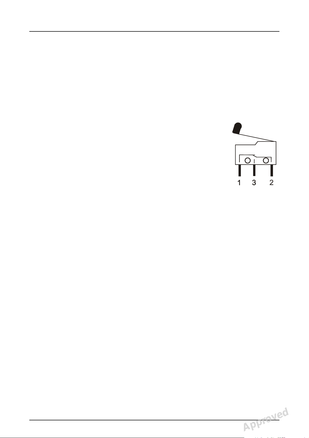
2.1 Microswitches and position indicators
There are 15 to 18 microswitches a nd
opto sensors in OP200 models to
detect the position of the various
movements of the equipment. All
switches are wired to the I/O Board,
and the microprocessor reads the
status of the switches every 20 ms. The
name of the swit ch is the same as the
name of the signal to the
microprocessor. Open switch is 5 V,
and closed switch is 0 V signal level in I/O Board. Their
operation can be checke d by using Servic e Prog ram Sr 74
IOC.
2.2 General, failure messages
In case of malfunction, the unit displays a failure message.
Various letters and numbers are disp la yed in the technique
factors display positions next to kV, mA and s. Failure code
classification is displayed next to kV. A special failure code
number is displayed next to mA with alphanumeric
information in the s-display.
kV display
Letters in the kV-display indicate the nature of the failure,
whether it is caused by user (eg. wrong collimator
selected), environment (eg. low line voltage) or protection
in the unit (eg. tubehead too hot), or whether there is a
serious defect in the unit, which disables the complete
operation (eg. program memory error):
200214 rev 3 Instrumentarium Dental 11
Reviewed: Rintamäki Markus 2008-05-26 15:43
Approved: Äärynen Teemu 2008-06-04 17:35
See PDM system to determine the status of this document. Printed out: 2015-04-10 11:48:23
Copyright © 2008 by PaloDEx Group Oy. All rights reserved.
D500211, 3
Approved

2 Electric trouble shooting
Ch Check. A failure caused by
the user.
Sy Safety. Temporary
malfunction or protection in
the unit, caused by the un it or
environment. Operation is
prohibited or te rminated to
protect the operator, patient
and the unit itself. (Eg. the
temperature in th e tu be head
assembly is too high due to
intensive use). After the
corrective action or the wait
time, the unit can be used.
Er Error. There is a serious
defect in the unit, and the
operation is therefore
prohibited to protect the
operator, patient and the unit
itself. (E g. Fa ilu re in the Co re
Module).
WARNING! If the unit is further used, FAIL failure may
cause malfunctio n.
mA display
The mA-display shows the actual numeric failure code.
Each failure code has a unique number, to differ one
malfunction from anoth er :
kV Ch Sy Er
mA 1 to 19 20 to 39 40 to 50
12 Instrumentarium Dental 200214 rev 3
Reviewed: Rintamäki Markus 2008-05-26 15:43
Approved: Äärynen Teemu 2008-06-04 17:35
See PDM system to determine the status of this document. Printed out: 2015-04-10 11:48:23
Copyright © 2008 by PaloDEx Group Oy. All rights reserved.
D500211, 3
Approved

2 Electric trouble shooting
s display
The exposure time display indicates the alphanumeric
short form explanation of the malfunction. This reminds the
user or the servicema n of what the actual numeric failure
code means, or sometimes numeric information of the
malfunction, eg. PC for personal computer and COL for
collimator.
kV Time display
Ch-failure PC, PAC, CEC, COL, POS, rEL,
PSE, rEo, EAr,
PAR, LbL, bPL, StP, HSP or
numbers
Sy-failure HHo, ArC, Inu, FIL, AEC, EEP, Por,
CCD, PoL, PoH, PoU, nSY, COL or
numbers
Er-failure CPU, FIL, InP
Failure code resetting
Ch failure codes can be reset by correcting the reason for
the failure code (eg. changing collimator po s ition).
Ch and Sy failures can be reset by pushing any key in the
control panel (up-down-right-left-OK) or in the patient
positioning panel.
Er failures can not be reset. Switch the unit off and on, to
test whether the failure was only temporary.
200214 rev 3 Instrumentarium Dental 13
Reviewed: Rintamäki Markus 2008-05-26 15:43
Approved: Äärynen Teemu 2008-06-04 17:35
See PDM system to determine the status of this document. Printed out: 2015-04-10 11:48:23
Copyright © 2008 by PaloDEx Group Oy. All rights reserved.
D500211, 3
Approved

2 Electric trouble shooting
2.3 Film unit failure messages
2.3.1 Ch 1 CAS
Problem: “ Ch 1 CAS “ error message is displayed.
Why? Cassette not ready for the exposure in QA
and panoramic progr ams .
How is it
detected?
At the beginning of the exposure the state
of the PANCASSW signal is read. The
indicator for panoramic film cassette,
optical sensor (D1), is located inside the
cassette holder, behind the cassette
carriage. When the cassette is inserted
the actuator on the cassette carriage
moves the cam away from the optical fork,
thus activating the PANCASSW signal.
Error occurs when the exposure, other
than cephalometric, is initiated and 1) the
signal is not active or 2) the signal has not
been inactive since the previous exp osure.
The exposure is prevented.
To ensure maximal image quality the
panoramic cassette can not be placed in
it’s holder while aqcuiring cephalostatic
image and vice versa.
Possible
causes:
Panoramic or
tomographic
cassette not
properly installed
or not in place.
Panoramic or
tomographic
cassette not
replaced since
the previous
exposure.
Trying to aqcuire
ceph image while
pan cassette
installed.
Check or test: Parts related:
Remove the cassette
Cassette
and reinsert unexposed
one.
- Error should clear.
- If not check the
microswitch operation.
Remove pan cassette.
14 Instrumentarium Dental 200214 rev 3
Reviewed: Rintamäki Markus 2008-05-26 15:43
Approved: Äärynen Teemu 2008-06-04 17:35
See PDM system to determine the status of this document. Printed out: 2015-04-10 11:48:23
Copyright © 2008 by PaloDEx Group Oy. All rights reserved.
D500211, 3
Approved

2 Electric trouble shooting
Possible
causes:
Signal
PANCASSW
passive in the
Core Module.
Check or test: Parts related:
Check the microswitch
operation & adjustment:
Press the cassette
Cassette
sensor
assembly
against the cassette
tunnel.
- If the error message
clears then problem with
the cassette sensor
alignment, adjust the
microswitch or opto
coupler.
- If the error stays then
check the wiring.
Check the wiring:
Microswitch
S23
- Check the connectors
and wires for open or
broken wire. Use the
wiring diagram.
or optocoupler,
SC4 or C19,
C18 in CR
units, X114,
C13, X6
- Check the wiring order
on microswitch or
optocoupler
Test the wiring :
- Use Sr 74 IOC. Press
cassette sensor to
check that the signal
status changes. When
signal is active (opto
sensor D1 free or
microswitch S23
closed), cassette is in
the cassette holder.
Signal is indica ted by In
0 LED8, lit LED
indicates the presence
of the cassette. If the
signal does not change
then use wiring diagram
and DVM (digital
voltmeter) to find the
problem.
200214 rev 3 Instrumentarium Dental 15
Reviewed: Rintamäki Markus 2008-05-26 15:43
Approved: Äärynen Teemu 2008-06-04 17:35
See PDM system to determine the status of this document. Printed out: 2015-04-10 11:48:23
Copyright © 2008 by PaloDEx Group Oy. All rights reserved.
D500211, 3
Approved

2 Electric trouble shooting
2.3.2 Ch 2 CAS (film unit)
Problem: “ Ch 2 CAS “ error message is display ed.
Why? Cephalostat cassette not ready with the
program P11 and P12.
How is it
detected?
Possible
causes:
Cephalostat
cassette not
properly installed
or not in place.
In OC200 models there is an indicator for
the cephalometric film cassette. This
microswitch (S 34) is located inside the
cassette holder. At the beginning of the
exposure the state of the CEPHCASSW
signal is read. Error occurs when the
cephalometric exposure is initiated and 1)
the signal is not active or 2) the signal has
not been inactive since the previous
exposure. The exposure is prevented.
Error occur also if cephalometric cassette is
installed and panoramic image acquicition
started.
Check or test: Parts related:
Remove the cassette.
Ceph cassette
Reinsert it.
- Error should clear.
- If not check the
microswitch operation.
16 Instrumentarium Dental 200214 rev 3
Reviewed: Rintamäki Markus 2008-05-26 15:43
Approved: Äärynen Teemu 2008-06-04 17:35
See PDM system to determine the status of this document. Printed out: 2015-04-10 11:48:23
Copyright © 2008 by PaloDEx Group Oy. All rights reserved.
D500211, 3
Approved

2 Electric trouble shooting
Possible
causes:
Cephalostat
cassette not
replaced since
the previous
exposure.
Check or test: Parts related:
Remove cassette and
replace with unexposed
Cassette
sensor
one.
Check the microswitch
operation & adjustment:
Press the cassette
against the cassette
sensor.
- If the error message
clears then problem is
with the cassette sensor
alignment. Adjust the
microswitch.
- If the error stays then
check the wiring or
adjust the switch.
Ceph cassette
installed while
PAN exposure
Remove ceph cassette Ceph cassette
200214 rev 3 Instrumentarium Dental 17
Reviewed: Rintamäki Markus 2008-05-26 15:43
Approved: Äärynen Teemu 2008-06-04 17:35
See PDM system to determine the status of this document. Printed out: 2015-04-10 11:48:23
Copyright © 2008 by PaloDEx Group Oy. All rights reserved.
D500211, 3
Approved

2 Electric trouble shooting
Possible
causes:
Signal
CEPHCASSW
passive in the
Core Module.
Check or test: Parts related:
Check the wiring:
Microswitch
S34, CC4,
- Check the connectors
and wires for open or
broken wire. Use wiring
diagram.
X130, CC2,
X110 or X121,
C13, X8, Core
Module
- Check the wiring order
on microswitch.
Test the wiring :
- Use Sr 74 IOC. Press
the cassette sensor to
check if the signal status
changes.
- If the signal does not
change, then use wiring
diagram and DVM to
find the problem.
- When switch is closed,
cassette is in the
cassette holder. Note
that the switch is
connected normally
closed, i.e. the switch is
closed when the
actuator is released.
Signal is indicated by
In4 LED5, lit LED
indicates the presence
of the cassette.
18 Instrumentarium Dental 200214 rev 3
Reviewed: Rintamäki Markus 2008-05-26 15:43
Approved: Äärynen Teemu 2008-06-04 17:35
See PDM system to determine the status of this document. Printed out: 2015-04-10 11:48:23
Copyright © 2008 by PaloDEx Group Oy. All rights reserved.
D500211, 3
Approved

2 Electric trouble shooting
2.3.3 Ch 3 COL (film unit)
Problem: “ Ch 3 COL “ error message is displayed.
Why? Wrong collimator selected.
How is it
detected
?
Error is generated wh en the pano ramic (P1 - P5),
or special (P6 -P10) exposure is initiated while the
panoramic collimator is not in the panoramic
position. Error is also generated when the
tomographic (P13 - P14) exposure is initiated
while the collimator is not in TOMO position.
Signals COL1SW to COL3SW are monitored in
the Core Module.
Possible
causes:
Collimator not
in PAN position
when
panoramic
(Program 1 to
5), TMJ or
sinus (Program
6 to 10)
selected.
Check or test: Parts
related:
Move the collimator to
Collimator.
correct position until it
“clicks”.
- Error should clear.
- If not check the microswitch
operation.
Collimator not
in TOMO
position
when Program
13 or 14
selected.
200214 rev 3 Instrumentarium Dental 19
Reviewed: Rintamäki Markus 2008-05-26 15:43
Approved: Äärynen Teemu 2008-06-04 17:35
See PDM system to determine the status of this document. Printed out: 2015-04-10 11:48:23
Copyright © 2008 by PaloDEx Group Oy. All rights reserved.
D500211, 3
Approved

2 Electric trouble shooting
Possible
causes:
Signal
COL1SW
passive and/or
COL2SW
active in the
Core Module.
Check or test: Parts
related:
Test the microswitch
Collimator.
operation: Move the
collimator.
- If the error stays then check
the wiring and microswitch
alignment.
- Remove THA cover.
Visually check that the
switches trigger according to
the code bar and that switch
levers move freely.
Check the wiring:
S31, S32,
S33, CC1,
- Check the connectors and
wires for open or broken
wire. Use wiring diagram.
X113, C13,
X8, Core
Module,
collimator
- Check the wiring order on
code disk
microswitch.
- If error happens at OT
upgrade, check the
collimator code disk, there
are two different models,
OC200 and TOMO. Refer t o
the Table on next page.
Test the wiring : Use Sr 74
IOC and move the coll imator
to check that the signal
status changes. Follow the
Table below.
- If the signals do not change
or are not correct then use
wiring diagram and/or DVM
to find the problem.
Valid OC200 & OC200 OT collimator switch combinations
(closed switch is active = +5V). There are two different
code bars, one for OC collimators and th e other for Ortho
Trans collimators:
20 Instrumentarium Dental 200214 rev 3
Reviewed: Rintamäki Markus 2008-05-26 15:43
Approved: Äärynen Teemu 2008-06-04 17:35
See PDM system to determine the status of this document. Printed out: 2015-04-10 11:48:23
Copyright © 2008 by PaloDEx Group Oy. All rights reserved.
D500211, 3
Approved

2 Electric trouble shooting
S 31
COL1S
W
S 32
COL2S
W
S 33
COL3S
W
COLLIMATOR
POSITION
closed closed open Quality Assurance
collimator
closed open open Panoramic collimator
closed
closed
closed
Cephalostat
collimator:
TOMO
collimator:
24 x 30 cm
AV or
10 x 12 in
AV or
*open
open closed closed 18 x 24 cm
*closed
*open
10 x 8 in AH
or
* TOMO
18 x 24 cm
AV
8 x 10 in AV
or
24 x 30 cm
AV or
8 x 10 in AV
or
10 x12 in AV
or
10 x 8 in AH
open open closed 18 x 24 cm
SV or
8 x 10 in SV
18 x 24 cm
SV or
8 x 10 in SV
open ope n open No valid collimator
200214 rev 3 Instrumentarium Dental 21
Reviewed: Rintamäki Markus 2008-05-26 15:43
Approved: Äärynen Teemu 2008-06-04 17:35
See PDM system to determine the status of this document. Printed out: 2015-04-10 11:48:23
Copyright © 2008 by PaloDEx Group Oy. All rights reserved.
D500211, 3
Approved

2 Electric trouble shooting
2.3.4 Ch 4 COL
Problem: “ Ch 4 COL “ error message is displayed.
Why? Wrong collimator selected for ceph
exposure.
How is it
detected?
Possible
causes:
Collimator not
in cephalostat
position when
program P11
or P12
selected
from the
control panel.
Error is generated when the cephalometric
exposure is initiated while the colli mator is
not in one of the cephalostat positions.
Signals COL1SW to COL3SW are
monitored in the Core Module.
Check or test: Parts
related:
Move the collimator to
Collimator.
correct position until it
“clicks”.
- Error should clear.
- If not check the microswitch
operation.
22 Instrumentarium Dental 200214 rev 3
Reviewed: Rintamäki Markus 2008-05-26 15:43
Approved: Äärynen Teemu 2008-06-04 17:35
See PDM system to determine the status of this document. Printed out: 2015-04-10 11:48:23
Copyright © 2008 by PaloDEx Group Oy. All rights reserved.
D500211, 3
Approved

2 Electric trouble shooting
Possible
causes:
Signal
COL1SW
active and/or
COL2SW
passive in the
Core Module.
Check or test: Parts
related:
Test the microswitch
Collimator.
operation: move the
collimator.
- If the error stays check the
wiring and micros w it ch
alignment.
- Remove THA cover.
Visually check that the
switches trigger according to
the code bar and that switch
levers move freely.
Check the wiring:
- Check the connectors and
wires for open or broken
wire.
- Check the wiring order on
microswitch.
- If error happens at OT
S31, S32,
S33, CC1,
X113, C13,
X8, Core
Module,
collimator
code bar
upgrade, check the type of
the collimator code disk:
there are two different
models.
Test wiring :
- Use Sr 74 IOC. Move the
collimator to check that the
signal status changes. If the
signal does not change, then
use wiring diagram and/or
DVM to find the problem.
200214 rev 3 Instrumentarium Dental 23
Reviewed: Rintamäki Markus 2008-05-26 15:43
Approved: Äärynen Teemu 2008-06-04 17:35
See PDM system to determine the status of this document. Printed out: 2015-04-10 11:48:23
Copyright © 2008 by PaloDEx Group Oy. All rights reserved.
D500211, 3
Approved

2 Electric trouble shooting
2.3.5 Sy 25 AEC
Problem: “Sy 25 AEC“ error message
is displayed.
Why? AEC base frequency
incorrect.
How is it detected? Occurs in the AEC mode if
the AEC base frequency
(AECFRQ during stand by) is
below 5 kHz. Exposure
sequence is interrupted.
NOTE! The unit can be used
in Manual exposure mode.
Possible cause Check or test Parts rela ted
+25V or -25V
operating voltages
not ok
Wrong AEC base
frequency.
Green LED’s on
AEC board and
Filament board.
Check the power
lines
Check base
frequency with “Sr
AEC board, X39,
Filament board,
X35, C13, X27,
Power Supply
board
AEC board
90 INS” option
“FRE” or “Sr 78
FrE”. Adjust to
5kHz.
AEC base
frequency drifts.
Check with Sr 90
INS
AEC board
Problem with
AEC board.
Open connector Check the wiring.
In CR models
check the 15V
regulator.
Broken Core
Module: signal
Check the signal
and its wiring.
FILT15.
Optocoupler.
24 Instrumentarium Dental 200214 rev 3
Reviewed: Rintamäki Markus 2008-05-26 15:43
Approved: Äärynen Teemu 2008-06-04 17:35
See PDM system to determine the status of this document. Printed out: 2015-04-10 11:48:23
Copyright © 2008 by PaloDEx Group Oy. All rights reserved.
AEC board, X116,
C13, X6, Core
Module
D500211, 3
Approved
 Loading...