

Page 1
Orthopantomograph® OP100 & OP100 D
Orthoceph® OC100 & OC100 D
Service Program Manual
Reviewed: Vartia Jussi 2006-10-03 08:31
Approved: Ukkonen Juha-Pekka 2006-10-11 09:53
See PDM system to determine the status of this document. Printed out: 2015-04-09 17:22:26
Copyright © 2006 by PaloDEx Group Oy. All rights reserved.
61014-IMG rev 3
Approved
61014-IMGTPH-1, 3
Page 2

Reviewed: Vartia Jussi 2006-10-03 08:31
Approved: Ukkonen Juha-Pekka 2006-10-11 09:53
See PDM system to determine the status of this document. Printed out: 2015-04-09 17:22:26
Copyright © 2006 by PaloDEx Group Oy. All rights reserved.
61014-IMGTPH-1, 3
Approved
Page 3

Copyright Code: 61014-IMG rev 3 Date: 20 September 2006
Document code 61014-IMGTPH-1 rev 3
Copyright © 09/2006 by PaloDEx Group Oy. All rights reserved.
Orthopantomograph
®
and Orthoceph® are registered trademarks of
Instrumentarium Dental. U.S. patents 4,641,336; 5,016,264; 5,425,065,
5,444,754, 6,731,717 and 6,829,326. German patent 4,344,745. Finnish
patents 112594 and 114383.
®
Orthopantomograph
and Orthoceph® are registered trademarks of
Instrumentarium Dental. U.S. patents 4,641,336; 5,016,264; 5,425,065,
5,444,754, 6,731,717 and 6,829,326. German patent 4,344,745. Finnish
®
patents 112594 and 114383. Windows
is trademark of Microsoft
Corporation in the United States of America and other countries. Pentium
is a registered trademark of Intel Corporation. Iomega® Jaz® is a
registered trademark of Iomega Corp.
Documentation, trademark and the software are copyrighted with all
rights reserved. Under the copyright laws the documentation may not be
copied, photocopied, reproduced, translated, or reduced to any electronic
medium or machine readable form in whole or part, without the prior
written permission of Instrumentarium Dental.
The original language of this manual is English.
Instrumentarium Dental reserves the right to make changes in
specification and features shown herein, or discontinue the product
described at any time without notice or obligation. Contact your
Instrumentarium Dental representative for the most current information.
®
Manufactured by Instrumentarium Dental
P.O. Box 20
FI-04301 Tuusula
FINLAND
Tel. +358 45 7882 2000
Fax. +358 45 7882 2506
For service, contact your local distributor.
Reviewed: Vartia Jussi 2006-10-03 08:31
Approved: Ukkonen Juha-Pekka 2006-10-11 09:53
See PDM system to determine the status of this document. Printed out: 2015-04-09 17:22:26
Copyright © 2006 by PaloDEx Group Oy. All rights reserved.
61014-IMGTPH-1, 3
Approved
Page 4

Reviewed: Vartia Jussi 2006-10-03 08:31
Approved: Ukkonen Juha-Pekka 2006-10-11 09:53
See PDM system to determine the status of this document. Printed out: 2015-04-09 17:22:26
Copyright © 2006 by PaloDEx Group Oy. All rights reserved.
61014-IMGTPH-1, 3
Approved
Page 5

Table of Contents
1 Introduction .............................................................................................................. 1
1.1 General .................................................................................................................................................................1
1.2 Exhibition mode................................................................................................................................................2
1.3 SR: test programs.............................................................................................................................................2
1.4 How to use SR features.................................................................................................................................4
2 Service program SR features ................................................................................. 7
2.1 SR 70 LOG: Display error log.......................................................................................................................7
2.2 SR 71 PAY: Set lease period.........................................................................................................................8
2.3 SR 72 LCA: lateral tmj image area adjustment..................................................................................9
2.4 SR 74 IOC: cpu input output check .......................................................................................................10
2.5 SR 76 PUP: Warming-up procedure for tubehead........................................................................18
2.6 SR 77 PRH: Preheat automatic adjustment......................................................................................19
2.7 SR 79 SUP: line voltage display...............................................................................................................20
2.8 SR 80 CRL: motor movement test .........................................................................................................21
2.9 SR 88 CAL: Ceph secondary collimator alignment information..............................................23
2.10 SR 89 COP: country options......................................................................................................................24
2.11 SR 90 PIN: Panorama installation program......................................................................................26
2.12 SR 91 CIN: Ceph installation program.................................................................................................28
2.13 SR 92 CHE: Installation check enable / disable settings .............................................................29
61014-IMG rev 3 Instrumentarium Dental i
Reviewed: Vartia Jussi 2006-10-03 08:31
Approved: Ukkonen Juha-Pekka 2006-10-11 09:53
See PDM system to determine the status of this document. Printed out: 2015-04-09 17:22:26
Copyright © 2006 by PaloDEx Group Oy. All rights reserved.
61014-IMGTPH-1, 3
Approved
Page 6
1 Introduction
1.1 GENERAL
Instrumentarium Dental Orthopantomograph® OP100 is a panoramic xray equipment for producing images of dentition, TM-joints and skull with
the possibility of linear tomography programs for producing longitudinal
and cross-sectional tomograms of the dentition. This software can be
used with any OP100 or OC100 model including OP100 CR, OP100 OT and
all digital models. In this manual name OP100 is used as general name for
all models unless stated otherwise.
The software is divided into two parts. User programs (Pr) are accessible
by the user and they have features for configuring their unit for daily use
and for changing technique factors to optimize image quality.
Maintenance & Service programs (Sr) are for technical people during
installation and service. Please refer to User Program chapter in OP100
User Manual for Pr program details.
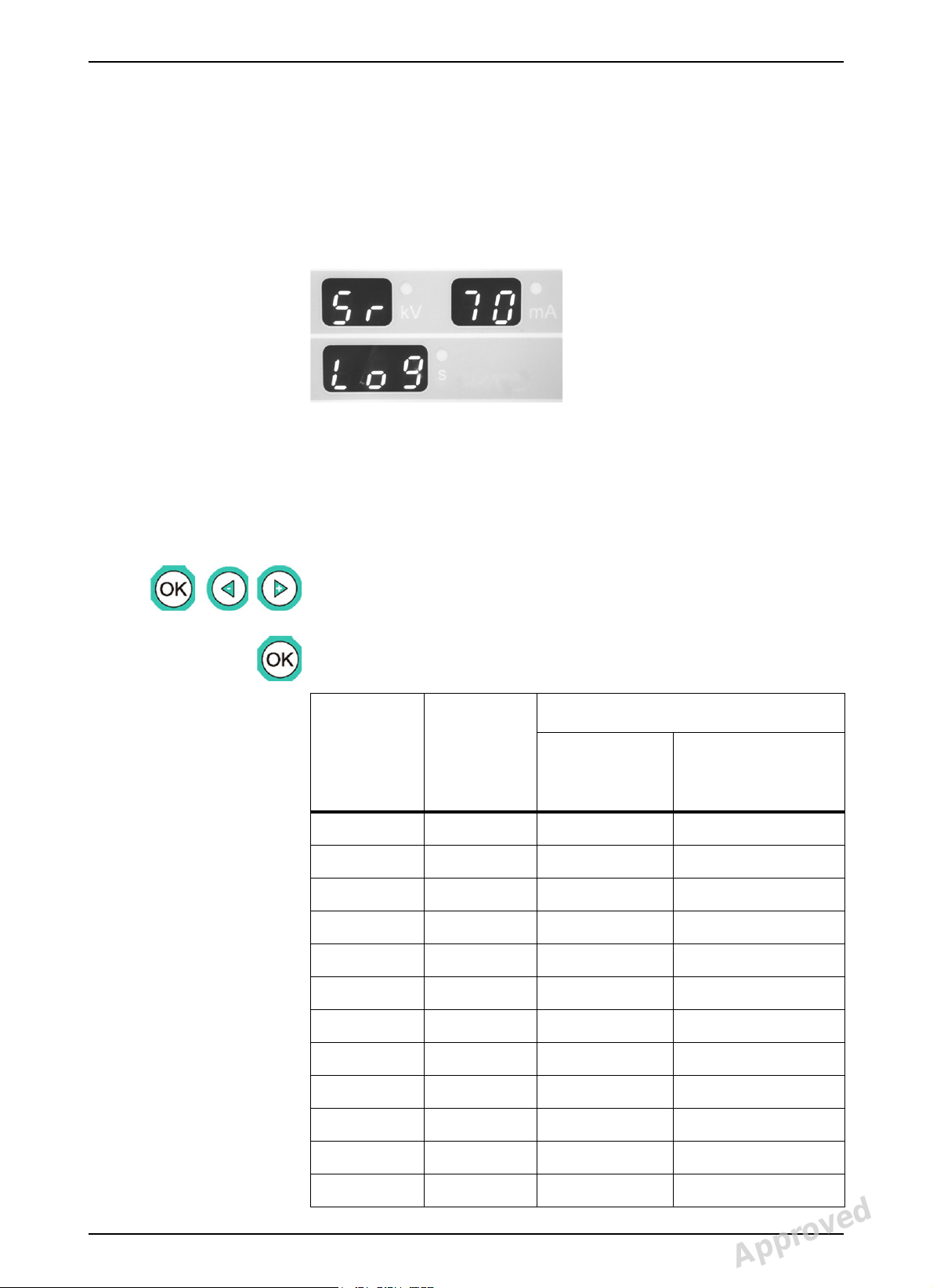
1 Introduction
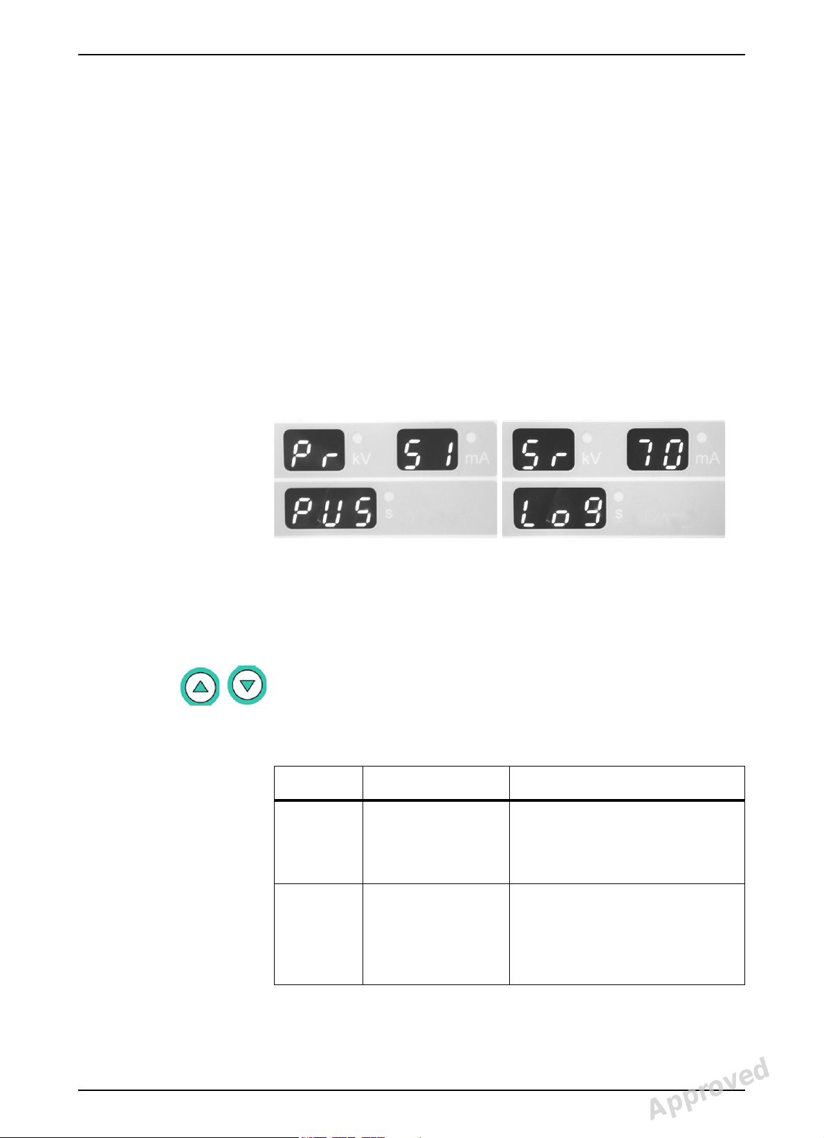
Letters Pr or Sr in the kV display indicate that the unit is in the user or
service programming mode. Numbers in the mA display indicate the
actual numeric code for each program. Letters in the exposure time
display indicate the mnemonic explanation for each program, to remind
the user of the actual numeric program code meaning.
After you have set OP100 to the service programming mode, different
service programs can be selected by pressing up and down buttons,
until the desired service program code appears on the display. The display
indicates the service program in the following form:
Display Value(s) Description
kV Sr The unit is in the service
programming mode, and the
serviceman is able to use the
service programs to test the unit.
mA 70 - 92 Indicates the actual numeric code
for respective service program.
View the functions with up and
down buttons and select with OK
button.
61014-IMG rev 3 Instrumentarium Dental 1
Reviewed: Vartia Jussi 2006-10-03 08:31
Approved: Ukkonen Juha-Pekka 2006-10-11 09:53
See PDM system to determine the status of this document. Printed out: 2015-04-09 17:22:26
Copyright © 2006 by PaloDEx Group Oy. All rights reserved.
61014-IMGTPH-1, 3
Approved
Page 7
1 Introduction
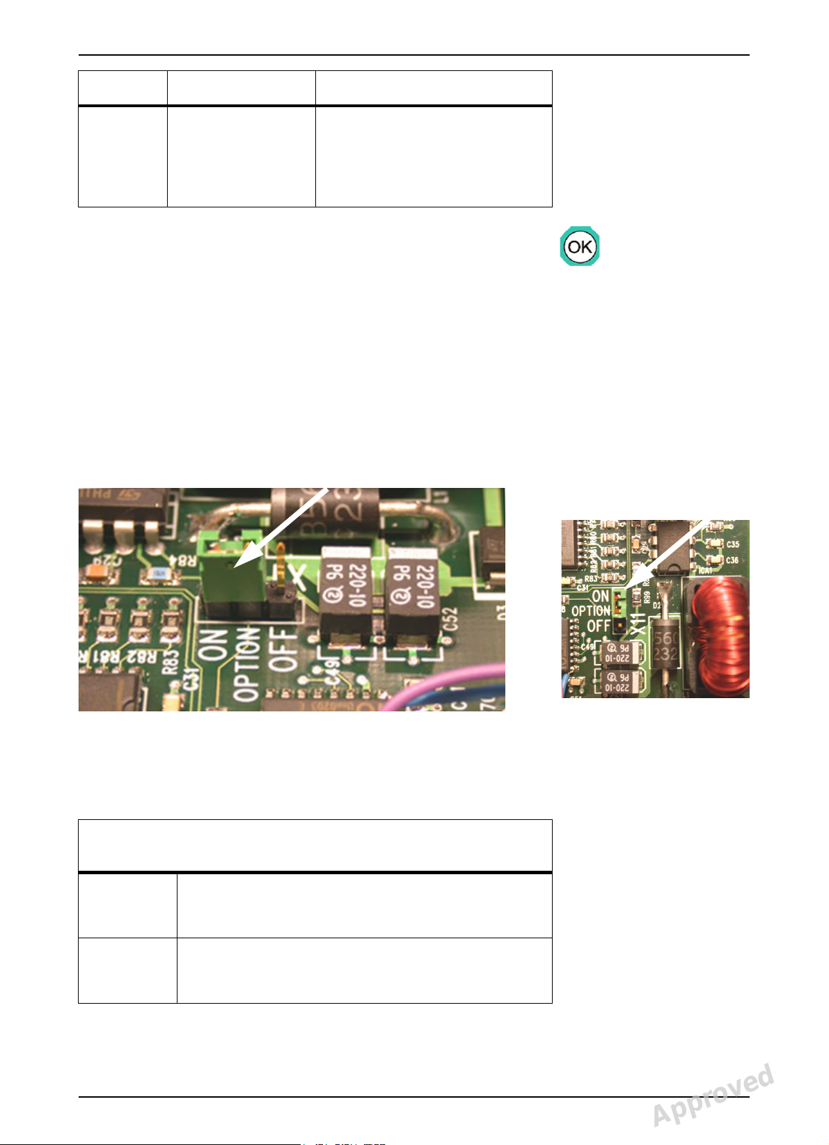
Fig 1.1. Jumber X 11 is set to ON.
Display Value(s) Description
sLog, PAy, LCA, IOC,
PUP, Prh, thA, SUP,
CrL, LAL, CAL, COP,
PIn, Che
Indicates the alphanumeric short
form for the explanation of the
service program, to remind the
serviceman what the numeric
program code means.
The displayed service program can be activated by pressing OK button.
After activating the service program the test starts. In programs which
require movements and / or exposure, the test starts when pressing the
exposure button.
After completing the test a tone indicates that the unit passed the test, or
respective failure code FAIL indicates that the test has failed. Repeat the
service program or select another Sr program.
1.2 EXHIBITION MODE
OP100 does not emit x-rays, when the OP100 has been set for an
exhibition mode. The exhibition mode is selected, when CPU option
jumper X 11 is set to ON.
1.3 SR: TEST PROGRAMS
SERVICE PROGRAM TESTS
REFERENCE TABLE
Sr
70
Log
Sr
71
PAy
2 Instrumentarium Dental 61014-IMG rev 3
Reviewed: Vartia Jussi 2006-10-03 08:31
Approved: Ukkonen Juha-Pekka 2006-10-11 09:53
See PDM system to determine the status of this document. Printed out: 2015-04-09 17:22:26
Copyright © 2006 by PaloDEx Group Oy. All rights reserved.
ERROR LOG PROGRAM
Scroll the failure code counters.
SET TRIAL PERIOD LIMIT
OP100 can be programmed to enable a number (10-
2000) of test exposures before OP100 shuts off.
61014-IMGTPH-1, 3
Approved
Page 8

SERVICE PROGRAM TESTS
REFERENCE TABLE
1 Introduction
Sr
72
LCA
Sr
74
IOC
Sr
76
PUP
Sr
77
Prh
Sr
79
SUP
Sr
80
CrL
LATERAL CASSETTE ADJUSTMENT (Film units only)
In Program 6 center Lateral TMJ-image areas can be
adjusted to be symmetrical by this program, instead of
adjusting microswitches. Adjustment - 0.25 - (+ 1.00)
cm, in steps of 0.1 mm.
INPUT / OUTPUT
Operation of CPU input and output signals is monitored
and displayed with control panel’s LED’s.
WARMING UP SEQUENCE
Tube warming up procedure.
PREHEAT ADJUSTMENT
Automatic preheat adjustment.
LINE VOLTAGE DISPLAY
Displays the line voltage continuously.
INDIVIDUAL MOTOR MOVEMENT TESTS
CA, ro and LI with film units
CE, ro and LI with digital units
Sr
81
bPL
Sr
87
LAL
Sr
88
CAL
Sr
89
COP
Sr
90
PIn
Sr
91
CIn
Not used
Not used
CEPH SECONDARY COLLIMATOR ALIGNMENT
INFORMATION
Monitoring secondary collimator position.
COUNTRY OPTIONS
Remote exposure only, Disable Ceph Collimator, Disable
AEC, Free kV-mA values, Select ceph mA, Ortho Zone,
Ortho TMJ and Ortho Trans
PANORAMA INSTALLATION PROGRAM
Exposure without movements and AEC frequency test.
CEPH INSTALLATION PROGRAM
For digital units only.
Cephalostat alignments.
Sr
INSTALLATION ENABLE/DISABLE CHECKING SETTINGS
92
ChE
61014-IMG rev 3 Instrumentarium Dental 3
Reviewed: Vartia Jussi 2006-10-03 08:31
Approved: Ukkonen Juha-Pekka 2006-10-11 09:53
See PDM system to determine the status of this document. Printed out: 2015-04-09 17:22:26
Copyright © 2006 by PaloDEx Group Oy. All rights reserved.
61014-IMGTPH-1, 3
Approved
Page 9
1 Introduction
NOTE!
NOTE!
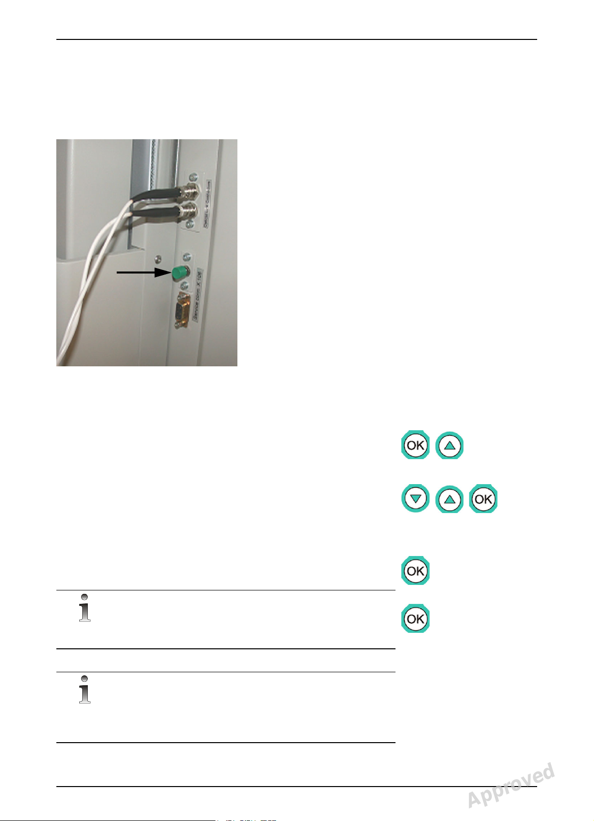
Fig 1.2. Button for the service programming mode.
1.4 HOW TO USE SR FEATURES
1 Switch the OP100 power off. Turn the unit back on while pressing the
service programming button. Do not release the button before you
see lights flashing in the control panel. Wait for a moment. Software
version is displayed during the memory check. Check that all leds are
lit. OP SEr is displayed in the control panel.
2 Press OK to enter the normal operating mode.
(Hint: This is defined in the Pr 51 PUS option settings.)
3 Change the normal operating mode to the service programming
mode by pressing and holding OK button for three seconds. Scroll
thru the Pr (user) programs by pressing up button and the Sr (service)
programs will be available after scrolling.
4 Use up and down buttons to view programs. Select one of the Sr
programs by pressing OK button.
5 Make the trouble shooting, adjustments or change settings. Use left
and right buttons to select option and settings. Follow the guidelines
for each Sr program described in the next chapter.
6 Press OK to store any changes to the OP100 memory. The recently
used program, eg. Sr 76 PUP, is displayed again.
If you change the parameters and forget to press OK or switch the power
off too early, the storing of any changes fails. Change and store again
Exit the service programming mode by pressing the OK button for three
seconds at the program selection level, or exit permanently by switching
OP100 power off.
4 Instrumentarium Dental 61014-IMG rev 3
Reviewed: Vartia Jussi 2006-10-03 08:31
See PDM system to determine the status of this document. Printed out: 2015-04-09 17:22:26
Copyright © 2006 by PaloDEx Group Oy. All rights reserved.
Approved: Ukkonen Juha-Pekka 2006-10-11 09:53
61014-IMGTPH-1, 3
Approved
Page 10

1 Introduction
Fig 1.3. OP100 EMC ed2 film unit DIP 8-microswitch positions
Fig 1.4. OP100 D EMC ed2 digital unit DIP 8-microswitch
positions
Switch # Feature
1 Film unit / Digital unit switch
2 Used for adapting old film unit main
cable
3 Used for adapting old film unit main
cable
4 Used for adapting old film unit main
cable
5 Colsw’t
6 Colsw’t
7 Colsw’t
8caectrq
61014-IMG rev 3 Instrumentarium Dental 5
Reviewed: Vartia Jussi 2006-10-03 08:31
Approved: Ukkonen Juha-Pekka 2006-10-11 09:53
See PDM system to determine the status of this document. Printed out: 2015-04-09 17:22:26
Copyright © 2006 by PaloDEx Group Oy. All rights reserved.
61014-IMGTPH-1, 3
Approved
Page 11
2 Service program SR features
2.1 SR 70 LOG: DISPLAY ERROR LOG
Select Sr 70 Log. The error log is displayed. Each logged error code is
shown on the display blinking with the current error log count. The values
may not be cleared.
View the CPU parameter memory (EEPROM) contents. This memory stores
the failure code counters and this information can be used for obtaining
OP100 D history data. Some failure counters have non-zero values at the
time of installation. This is normal.
2 Service program SR features
Procedure:
1 Select the program Sr 70 Log and press OK. View memory contents
by pressing left and right buttons. KV display shows the memory
location and mA/s displays show the contents, if any.
2 Press OK to exit the program. Sr 70 Log is displayed again. Select
another program or exit the service programming mode.
kV-display
Ch / Sy / Er
Ch 05
Sy 13 LbL / “value“ < 10
Sy 21 HHo / “value“ < 10
Sy 22 Arc / “value“ < 10
Sy 23 InV / “value“ < 10
mA-display
error
number
Second / dose - display
Error name
AND
counter value
o o o
/ “value“
Typical value
at the time of
installation
< 10
Sy 24 FIL / “value“ < 10
Sy 25 AEC / “value“ < 10
Sy 27 Por / “value“ < 10
Sy 28 PoC / “value“ < 10
Sy 29 PoL / “value“ < 10
Sy 30 PoH / “value“ < 10
Sy 31 PoU / “value“ < 10
61014-IMG rev 3 Instrumentarium Dental 7
Reviewed: Vartia Jussi 2006-10-03 08:31
Approved: Ukkonen Juha-Pekka 2006-10-11 09:53
See PDM system to determine the status of this document. Printed out: 2015-04-09 17:22:26
Copyright © 2006 by PaloDEx Group Oy. All rights reserved.
61014-IMGTPH-1, 3
Approved
Page 12

2 Service program SR features
kV-display
Ch / Sy / Er
mA-display
error
number
Second / dose - display
Error name
AND
counter value
Typical value
at the time of
installation
Sy 1 nSY (not used)
Sy 30 Poc / “value”
Sy 32 PoA / “value“ < 10
Sy 28 CCd / “value“ < 10
Er 40 CPU / “value“ < 10
Er 43 LIN / “value“ < 10
Er 44 FIL / “value“ < 10
Er 45 InP / “value“ < 10
2.2 SR 71 PAY: SET LEASE PERIOD
OP100 can be programmed to enable a selected number of exposures,
after which the exposure is prohibited and the control panel immediately
displays a message Er 46 PAy. This feature can be used for equipment
leasing and customer trial purposes.
Select Sr 71 PAy and adjust the lease count. The number is editable in the
range 0...2000 with the special value OFF, when this feature is disabled.
Having the number 0 selected will activate Er 46 PAy and prevent
exposures. Other numbers will adjust the stored exposure counter into a
number above the total exposure count.
In normal operation the user can test, if the test limit has been set, by
pressing OK button: first the cumulative exposure counter value and then
the number of free exposures are displayed with all indicators lit
momentarily.
Procedure:
1 Select program Sr 71 Pay. The time display in the control panel
shows OFF or a number from 1 to 2000.
2 If the feature was disabled, OFF is displayed. Use left and right
buttons to enable this feature and change the number of free
exposures. Numbers can be changed faster by holding down right
button.
3 Select OFF, if you want to disable this feature.
8 Instrumentarium Dental 61014-IMG rev 3
Reviewed: Vartia Jussi 2006-10-03 08:31
Approved: Ukkonen Juha-Pekka 2006-10-11 09:53
See PDM system to determine the status of this document. Printed out: 2015-04-09 17:22:26
Copyright © 2006 by PaloDEx Group Oy. All rights reserved.
61014-IMGTPH-1, 3
Approved
Page 13

2 Service program SR features
4 Press OK to store these changes into OP100 memory, Sr 71 PAY will
be displayed again. Select another program or exit the service
programming mode.
2.3 SR 72 LCA: LATERAL TMJ IMAGE AREA
ADJUSTMENT
(for film units only)
This program may be needed when cassette movement microswitches
are adjusted or replaced and when the CPU board or its EEPROM is
replaced. In cassette holders with optical sensors no adjustment is usually
necessary.
With imaging program P7 (TMJ Lateral view jaw closed and open) first
two jaws are exposed and shown on the film edges, then the second
exposure is started on the return movement and images are shown in the
middle. The center pair image area can be adjusted to be symmetric in
respect to the other image pair by using this program, instead of adjusting
microswitches. The adjustment is -10...+2.5 mm, in steps of 0.1 mm (-
1.00...+0.25 cm in the display).
Procedure:
1 Use customers latest TMJ Lateral view jaw closed and open x-ray
film, or take one:
2 Select imaging Program P7, lowest technique factors and take the
exposure. Process the film.
3 Check the film for center image pair symmetry. Calculate the amount
(-0.25...+1.00 cm) of correction needed.
4 Select program Sr 72 LCA to enter the service programming mode.
Control panel shows a number from -0.25 to 1.00. The number
61014-IMG rev 3 Instrumentarium Dental 9
Reviewed: Vartia Jussi 2006-10-03 08:31
Approved: Ukkonen Juha-Pekka 2006-10-11 09:53
See PDM system to determine the status of this document. Printed out: 2015-04-09 17:22:26
Copyright © 2006 by PaloDEx Group Oy. All rights reserved.
61014-IMGTPH-1, 3
Approved
Page 14

2 Service program SR features
indicates the adjustment of the positioning of the second image pair
areas (center) compared to the first image pair areas (on each side).
5 Use left and right buttons in order to shift the middle image pair in
steps of 0.5 mm to the left or right, respectively when the film has a
side marking “ L “ on the right.
6 Press OK to store these changes into OP100 memory. OP100 will
display Sr 72 LCA again. Select another program or exit the service
programming mode.
7 Exit the service programming mode by switching the OP100 power
off. Turn OP100 on again. Select imaging program 7 and lowest
technique factors. Take the exposure. Process the film. Check the film
for symmetry. If the result was not satisfactory, return to Sr 72 LCA
program and repeat steps 1 to 6.
2.4 SR 74 IOC: CPU INPUT OUTPUT CHECK
This program is used for checking the state of the CPU inputs and outputs
- without opening all the covers of OP100 main assemblies. It is useful for
trouble shooting CPU input signal problems, eg. the various
microswitches, user buttons and opto couplers.
Select Sr 74 IOC from the control panel. Use left and right buttons to
switch between the different displayed fields. There are multiple fields
(around 24) which display different ”shell variables”. The values of the
input / output variables is displayed with the LEDs on the control panel
and the current field with a number and either H (high byte) or L (low byte)
along the number.
The program shows whether the signal from some particular switch
reaches the CPU or not. The output signals are somewhat arbitrary, but
the information may be useful in some situations.
1 Select Sr 74 IOC and press OK.
2 Use left and right buttons to select different tests (0L - 0H - 1L - 1H -
2L - 2H - 3L - 3H - 4L - 4H - 5L - 5H - 6L - 6H).
3 Some of the program selection LED’s on the control panel are lit
showing the state of the signal port; LED 1 (standard panoramic
program) being bit 0 of the port and LED 2 (child panoramic) being bit
1 etc.
4 Use the tables of the input and output signals with the corresponding
I/O port and bit. Use CPU Board schematics to follow signals and
refer also to other volumes of the Service Manual for various
microswitch states.
10 Instrumentarium Dental 61014-IMG rev 3
Reviewed: Vartia Jussi 2006-10-03 08:31
Approved: Ukkonen Juha-Pekka 2006-10-11 09:53
See PDM system to determine the status of this document. Printed out: 2015-04-09 17:22:26
Copyright © 2006 by PaloDEx Group Oy. All rights reserved.
61014-IMGTPH-1, 3
Approved
Page 15

2 Service program SR features
NOTE!
The control panel display will be updated with a delay. This should be
understood when interpreting movements and other output signals. Stop
the movement by pressing any button to see the correct output status.
5 After testing return to the program viewing level. Press OK button
again. Sr 74 IOC is displayed again. Select another program or exit
the service programming mode.
Sr 74 IOC, Input test 0L
Cassette and Linear Movements
Signal name Description (Status, when LED on) LED
PROJLIT Projector lights 1
OUT1 not connected
OUT2 not connected
OUT3 not connected
PILLED Pillar layer adjustment LED 6
CENLED Center layer adjustment LED 7
PATLED Patient layer adjustment LED 8
OUT4 not connected
Sr 74 IOC, Input test 0H
Laser & DC motors
Signal name Description (Status, when LED on) LED
OUT5 not connected
LASLIT patient positioning lasers
XDIR
XENA
ZDIR up/down movement direction
ZENA up/down enable
RACKDIR cassette rack direction
RACKENA cassette rack enable
ZUP upwards 7
ZDOWN downwards 6, 7
61014-IMG rev 3 Instrumentarium Dental 11
Reviewed: Vartia Jussi 2006-10-03 08:31
Approved: Ukkonen Juha-Pekka 2006-10-11 09:53
See PDM system to determine the status of this document. Printed out: 2015-04-09 17:22:26
Copyright © 2006 by PaloDEx Group Oy. All rights reserved.
61014-IMGTPH-1, 3
Approved
Page 16

2 Service program SR features
Sr 74 IOC, Input test 0H
Laser & DC motors
RACKUP Cassette rack up (film unit) 8, 9
RACKDOWN Cassette rack down (film unit) 9
Sr 74 IOC, Input test 1L
Stepper motors
Signal name Description (Status, when LED on) LED
CASDIR Cassette movement director
CASENA Cassette enable
ROTDIR Rotation direction
ROTENA Rotation enable
CEPHDIR Ceph scanning direction
CEPHENA Ceph scanning enabling
LINDIR Linear movement direction
LINENA Linear movement enable
Sr 74 IOC, Input test 1H
CCD power & image
Signal name Description (Status, when LED on) LED
PPOWER CCD powers to panoramic head
PIMAGE CCD image out of the CCD (pan)
CPOWER CCD powers to cephalometric head
CIMAGE CCD image out of the CCD (Ceph)
TPOWER Not connected
TIMAGE Not connected
CLASLIT Ceph laser (in up/down panel)
CPIO31 Not connected
12 Instrumentarium Dental 61014-IMG rev 3
Reviewed: Vartia Jussi 2006-10-03 08:31
Approved: Ukkonen Juha-Pekka 2006-10-11 09:53
See PDM system to determine the status of this document. Printed out: 2015-04-09 17:22:26
Copyright © 2006 by PaloDEx Group Oy. All rights reserved.
61014-IMGTPH-1, 3
Approved
Page 17

2 Service program SR features
Sr 74 IOC, Input test 2L
Exposure
Signal name Description (Status, when LED on) LED
EXPSW
Exposure button on control panel 1, 4
(Ctrl panel)
INSTRUSW 2
MAOK Not connected
Remote expsw Remote control exposure switch
IN3 Not connected
MAINS Not connected
IN2 Not connected
Sr 74 IOC, Input test 2H
First movement switches
Signal name Description (Status, when LED on) LED
TUBEFAIL
PANCASSW Panoramic cassette in 2
CASLIMSW Cassette limit switch 3
CASMIDSW Cassette middle switch 4
LINMIDSW Linear movement middle switch 6
LINLIMSW Linear limit switch 7
RACKMIDSW Cassette rack middle switch 8
RACKLIMSW Cassette rack limit switch 9
Sr 74 IOC, Input test 3L
Signal name Description (Status, when LED on) LED
Not connected
Not connected
Not connected
Not connected
Not connected
Not connected
Not connected
Not connected
61014-IMG rev 3 Instrumentarium Dental 13
Reviewed: Vartia Jussi 2006-10-03 08:31
Approved: Ukkonen Juha-Pekka 2006-10-11 09:53
See PDM system to determine the status of this document. Printed out: 2015-04-09 17:22:26
Copyright © 2006 by PaloDEx Group Oy. All rights reserved.
61014-IMGTPH-1, 3
Approved
Page 18

2 Service program SR features
Sr 74 IOC, Input test 3H
Signal name Description (Status, when LED on) LED
Not connected
Not connected
Not connected
Not connected
Not connected
Not connected
Not connected
Not connected
Sr 74 IOC, Input test 4L
Patient positioning panel buttons
Signal name Description (Status, when LED on) LED
PATPOSLEFT Patient positioning button, left side 2
PATPOSRIGHT Patient positioning button, right side 1
PILWARD Retrusion (progenie) occlusion 3
CENWARD Normal occlusion 4
14 Instrumentarium Dental 61014-IMG rev 3
Reviewed: Vartia Jussi 2006-10-03 08:31
Approved: Ukkonen Juha-Pekka 2006-10-11 09:53
See PDM system to determine the status of this document. Printed out: 2015-04-09 17:22:26
Copyright © 2006 by PaloDEx Group Oy. All rights reserved.
61014-IMGTPH-1, 3
Approved
Page 19

2 Service program SR features
Sr 74 IOC, Input test 4L
Patient positioning panel buttons
PATWARD Protrusion (prognathie) occlusion 6
TEMPFAIL Tubehead too warm
SERVICESW Service mode switch 8
IN1 Not connected
Sr 74 IOC, Input test 4H
Collimator & patient positioning panel
Signal name Description (Status, when LED on) LED
COL1SW Panoramic collimator 1
COL2SW Cephalo collimator 2
COL3SW Ortho Trans collimator 2, 3
STARTPOSLEF 4, 6
STARTPOSRIG 4, 6
PROJTRIG 7
ZDOWN 8
ZUP 9
Sr 74 IOC, Input test 5L
Cephalo
Signal name Description (Status, when LED on) LED
CEPHLOK/
Ceph scanning beam on the left
CEPH1CAS
CEPHCOK Ceph scanning beam on the center
CEPHROK Ceph scanning beam on the right
CEPHLATPA 4
CEPH2CAS Not Connected
CEPH3CAS Not Connected
CEPH4CAS Not Connected
CEPHL Ceph left hand side 7
61014-IMG rev 3 Instrumentarium Dental 15
Reviewed: Vartia Jussi 2006-10-03 08:31
Approved: Ukkonen Juha-Pekka 2006-10-11 09:53
See PDM system to determine the status of this document. Printed out: 2015-04-09 17:22:26
Copyright © 2006 by PaloDEx Group Oy. All rights reserved.
61014-IMGTPH-1, 3
Approved
Page 20

2 Service program SR features
Sr 74 IOC, Input test 5L
Cephalo
CEPHR Ceph right hand side 6
CEPHDOWN Ceph up
CEPHUP Ceph down
Sr 74 IOC, Input test 5H
Second movements switches
Signal name Description (Status, when LED on) LED
ROT1SW name ???
ROT2SW name ???
ROT3SW name ???
ROT4SW name ???
ZMIDSW up/down middle switch 6
ZLIMSW up/down limit switch 7
CEPHMIDSW Ceph scanning middle switch 8
CEPHLIMSW Ceph scanning limit switch 9
Fig 2.1. Led procedures concerning movement of the rotating unit.
16 Instrumentarium Dental 61014-IMG rev 3
Reviewed: Vartia Jussi 2006-10-03 08:31
Approved: Ukkonen Juha-Pekka 2006-10-11 09:53
See PDM system to determine the status of this document. Printed out: 2015-04-09 17:22:26
Copyright © 2006 by PaloDEx Group Oy. All rights reserved.
61014-IMGTPH-1, 3
Approved
Page 21

2 Service program SR features
Sr 74 IOC, Input test 6L
First control panel buttons
Signal name Description (Status, when LED on) LED
CP_BUTTON0
OK button
CP_BUTTON1
Right button
CP_BUTTON2
Down button
CP_BUTTON3
Left button
CP_BUTTON4 Not Connected 5
CP_BUTTON5
Up button
CP_BUTTON6 Not Connected
CP_BUTTON7 Not Connected
1
2
3
4
6
Sr 74 IOC, Input test 6H
Second control panel buttons
Signal name Description (Status, when LED on) LED
CP_BUTTON8 Not applicable
CP_BUTTON9 Not applicable
CP_BUTTON10 Not applicable
CP_BUTTON11 Not applicable
CP_BUTTON12 Not applicable
CP_BUTTON13 Not applicable
CP_BUTTON14 Not applicable
CP_BUTTON15 Not applicable
61014-IMG rev 3 Instrumentarium Dental 17
Reviewed: Vartia Jussi 2006-10-03 08:31
Approved: Ukkonen Juha-Pekka 2006-10-11 09:53
See PDM system to determine the status of this document. Printed out: 2015-04-09 17:22:26
Copyright © 2006 by PaloDEx Group Oy. All rights reserved.
61014-IMGTPH-1, 3
Approved
Page 22

2 Service program SR features
WARNING!
2.5 SR 76 PUP: WARMING-UP PROCEDURE FOR
TUBEHEAD
This special program generates x-rays.
Purpose of this program is to enable testing of a defective tubehead
assembly, or warming up procedure of the replacement of tubehead
assembly.
Procedure:
1 Select program Sr 76 PUP. Make the exposure. OP100 exposes with
the lowest kV / mA values.
2 Repeat the exposure. No need to wait 15 seconds between the
exposures as usually, but the exposures can be done sequentially.
The next exposure can be taken right after the previous one. kV / mA
starts rising automatically from 20 kV / 1 mA, one step after each 3.2
s exposure, until 85 kV / 13 mA is reached:
Sr 76 PUP: kV & mA Feedback Reference Voltages
kV mA s (VkVref) (VmAref)
20 1.0 3.2 (1.00 V) (0.24 V)
30 1.0 3.2 (1.51 V) (0.24 V)
40 1.0 3.2 (2.00 V) (0.24 V)
50 1.0 3.2 (2.49 V) (0.24 V)
54 1.0 3.2 (2.71 V) (0.24 V)
57 1.0 3.2 (2.84 V) (0.24 V)
60 1.0 3.2 (3.00 V) (0.24 V)
63 1.0 3.2 (3.16 V) (0.24 V)
66 1.0 3.2 (3.31 V) (0.24 V)
70 1.0 3.2 (3.49 V) (0.24 V)
73 1.0 3.2 (3.67 V) (0.24 V)
77 1.0 3.2 (3.84 V) (0.24 V)
81 1.0 3.2 (4.06 V) (0.24 V)
18 Instrumentarium Dental 61014-IMG rev 3
Reviewed: Vartia Jussi 2006-10-03 08:31
Approved: Ukkonen Juha-Pekka 2006-10-11 09:53
See PDM system to determine the status of this document. Printed out: 2015-04-09 17:22:26
Copyright © 2006 by PaloDEx Group Oy. All rights reserved.
61014-IMGTPH-1, 3
Approved
Page 23

2 Service program SR features
NOTE!
WARNING!
Sr 76 PUP: kV & mA Feedback Reference Voltages
85 1.0 3.2 (4.25 V) (0.24 V)
85 2.0 3.2 (4.25 V) (0.49 V)
85 2.5 3.2 (4.25 V) (0.61 V)
85 3.2 3.2 (4.25 V) (0.76 V)
85 4.0 3.2 (4.25 V) (0.96 V)
85 5.0 3.2 (4.25 V) (1.22 V)
85 6.3 3.2 (4.25 V) (1.53 V)
85 8.0 3.2 (4.25 V) (1.92 V)
85 10.0 3.2 (4.25 V) (2.43 V)
85 13.0 3.2 (4.25 V) (3.06 V)
3 Complete one exposure by each technique factors listed above. In
case of arcing and / or breakdown, start this test from the beginning
(by pressing OK button twice).
4 If an arc or high voltage breakdown occurs in the tubehead during
exposure, this program is terminated and FAIL failure code will
appear on the display.
5 If repetitive arcing and/or breakdowns occurred, consult
Instrumentarium Imaging Technical Service.
It is also recommended that OP100, which has not been used for three
months or more, should be warmed up with this program. Always run this
program after the tubehead assembly replacement.
6 Press OK again to return to the program viewing level. Sr 76 PUP is
displayed.
7 After the test set OP100 for normal operation mode and make a
panoramic exposure (Program 1) with maximum technique factors.
2.6 SR 77 PRH: PREHEAT AUTOMATIC ADJUSTMENT
This special program generates x-rays.
Select Sr 77 Prh. Default exposure parameters are shown with the current
preheat offset parameter in the time display. The kV and mA levels cannot
be edited. Press the exposure button continuously; the exposure will be
made. The preheat display starts to increase and the filament feedback is
monitored. If a correct level is reached the exposure stops and the final
filament preheat offset reference value is left in the time display. The value
can be edited with the left / right buttons; don’t do it, but leave the
program by pressing OK button. The value is stored into non-volatile
61014-IMG rev 3 Instrumentarium Dental 19
Reviewed: Vartia Jussi 2006-10-03 08:31
Approved: Ukkonen Juha-Pekka 2006-10-11 09:53
See PDM system to determine the status of this document. Printed out: 2015-04-09 17:22:26
Copyright © 2006 by PaloDEx Group Oy. All rights reserved.
61014-IMGTPH-1, 3
Approved
Page 24

2 Service program SR features
NOTE!
memory. Purpose of this program is to make the unit to adjust it’s preheat
level of the filament automatically.
Procedure:
1 Press the exposure button continuously. Unit makes an exposure
with 85 kV.
2 Preheat level starts to rise from 0 by increasing preheat reference
slowly, and the unit checks the mA level at the same time. The
preheat reference data is displayed in the time display.
3 When the desired mA level is reached, program terminates the
exposure. Return to program viewing level. Press OK to store the
current preheat reference into the EEPROM memory.
The value should be between 50 and 60.
4 Press OK to return the program viewing level. Sr 77 PRH is displayed
again. Select another program or exit the service programming
mode.
2.7 SR 79 SUP: LINE VOLTAGE DISPLAY
Select Sr 79 SUP to check line supply voltage.
Line voltage is calculated from a measured incoming +25V supply in the
Filament Control Board. Measured line voltage is shown in the time
display.
Procedure:
1 Select program Sr 79 SUP. The display shows the approximate line
voltage value:
Inaccuracy of Line Voltage Measurement
230 VAC Line 110 VAC Line
20 Instrumentarium Dental 61014-IMG rev 3
Reviewed: Vartia Jussi 2006-10-03 08:31
Approved: Ukkonen Juha-Pekka 2006-10-11 09:53
See PDM system to determine the status of this document. Printed out: 2015-04-09 17:22:26
Copyright © 2006 by PaloDEx Group Oy. All rights reserved.
61014-IMGTPH-1, 3
Approved
Page 25

2 Service program SR features
NOTE!
Inaccuracy of Line Voltage Measurement
± 5 VAC ± 3 VAC
2 Press OK to return to the program viewing level. Sr 79 SUP is
displayed again. Select another program or exit the service
programming mode.
2.8 SR 80 CRL: MOTOR MOVEMENT TEST
Select Sr 80 CrL. The procedure allows test drives for different procedures
with and without exposure. The used motor can be selected with the
lowest field and is shown in the kV display as either CA (cassette), ro
(rotation) or LI (linear) with film units. In digital models CA is replaced by CE
(cephalostat). In the test mode the carriage is driven from the start of the
current position to the end (as long as the exposure button is held down.)
The final display shows the accumulated error at the end of the procedure
in percent (unless too big movement error which results in failure!). The
speeds and accelerations are much above the normal values and motor
specific.
During routine service, the movement tests need to be done for each
movement motor only once in each direction with speed factor 1 and
number of accelerations 2. (See the following detailed instructions, steps 4
and 5!). Further testing is necessary for extensive troubleshooting only.
AEC mode Manual mode Test mode
no function In manual mode a
static exposure is
active during
In the test mode the
movement test is
made without x-rays.
movement test. The
exposure values can be
manually selected.
Motor movement speeds
Motor Speed Speed factor Total speed
CA (cassette) 50 mm/s 1 50 mm/s
61014-IMG rev 3 Instrumentarium Dental 21
Reviewed: Vartia Jussi 2006-10-03 08:31
Approved: Ukkonen Juha-Pekka 2006-10-11 09:53
See PDM system to determine the status of this document. Printed out: 2015-04-09 17:22:26
Copyright © 2006 by PaloDEx Group Oy. All rights reserved.
61014-IMGTPH-1, 3
Approved
Page 26

2 Service program SR features
NOTE!
Motor movement speeds
Motor Speed Speed factor Total speed
CE (cephalostat) 50 mm/s 1 50 mm/s
RO (rotation)
15
o
/s
1
15o/s
LI (linear) 15 mm/s 1 15 mm/s
Motor movement speeds
Motor Speed Speed factor Total speed
CA (cassette) 50 mm/s 2 100 mm/s
CE (cephalostat) 50 mm/s 2 100 mm/s
RO (rotation)
15
o
/s
2
30o/s
LI (linear) 15 mm/s 2 30 mm/s
The purpose of this program is to check that there is enough torque in the
rotational, linear or cassette movement: the stepping motor and motor
control circuit operate properly, there is enough friction and the
movement does not slip nor get stuck. Tests are to be done in both
directions separately.
Procedure:
1 Select program Sr 80 CrL. Movement test is activated by pressing
and holding down the exposure button.
2 The kV display shows the type of motor movement (CA, CE, ro or LI).
3 The mA display shows the amount (1-5) of accelerations per one
movement. The amount tells how many accelerating movement are
done in one stroke.
4 The time display shows the velocity factor 0.1-2.5. This can be altered
manually to perform the test with different speeds.
The minimum requirements for CA, CE, ro and LI movement tests:
2 accelerations and velocity factor 1.
The other value choices are for more precise trouble shooting
investigation for the movements.
Movement is done according to settings and only to one direction at a
time. At the end the displayed value in the time field should be written
down. Then the value shall be confirmed by pressing OK and the test
movement can be done to the other direction. The second final value
should be written down also. These two values should be compared to
each other and the result should either be accepted or rejected according
to the limit values shown on the table below.
22 Instrumentarium Dental 61014-IMG rev 3
Reviewed: Vartia Jussi 2006-10-03 08:31
Approved: Ukkonen Juha-Pekka 2006-10-11 09:53
See PDM system to determine the status of this document. Printed out: 2015-04-09 17:22:26
Copyright © 2006 by PaloDEx Group Oy. All rights reserved.
61014-IMGTPH-1, 3
Approved
Page 27

2 Service program SR features
Motor
movement test
Maximum difference
of the two
final values *)
CA (cassette) 1.0 mm
CE (cephalostat) 1.0 mm
ro (rotation) 2.0°
LI (linear) 1.2 mm
*) Examples of calculating the difference:
First test ends with 0.7, second test ends with 0.2.
Difference is 0.7-0.2=0.5.
If first value is 0.3 and second value is -0.3, the difference is
0.3-(-0.3)=0.6.
Acceleration
1 or 3 Time 1.25
1 or 3 Time 1.25
1 or 5 Time 1.5
1 or 3 Time 1.5
5 Display shows the actual rotation in degrees, from 0° to 200° and
back. Note that figure 1.5 indicates that the motor is loosing pulses
during acceleration that correspond to 1.5° rotation, and
-1.5 indicates that the drive mechanics is sliding during braking
sequence that correspond to 1.5° rotation.
6 Press OK button. If test result is out of limit FAIL message appears to
the time display accordingly after the program has been completed.
7 To test the movement back and forth keep pressing the exposure
button during the first movement. Then release the button, write the
number down and press OK button for confirmation. For second
movement press and hold down the exposure button again.
8 To start test the movement in opposite direction, press either the
patient positioning button or the start position button. The rotating
unit will turn to the opposite side. Press the exposure button.
9 If the test failed and FAIL was displayed, check the microswitches,
friction surface, drive wheel and its tension, stepping motor and its
driving circuitry, cable C 13 inside the rotating unit.
10 Repeat the test when needed or return to the program viewing level
by pressing OK button.
2.9 SR 88 CAL: CEPH SECONDARY COLLIMATOR
ALIGNMENT INFORMATION
Select Sr 88 CAL. This procedure allows disabling the THA rotation
compensation based on the x-ray beam location on the beam alignment
board. Normally this option should be on to allow the unit to correct small
beam alignment errors.
61014-IMG rev 3 Instrumentarium Dental 23
Reviewed: Vartia Jussi 2006-10-03 08:31
Approved: Ukkonen Juha-Pekka 2006-10-11 09:53
See PDM system to determine the status of this document. Printed out: 2015-04-09 17:22:26
Copyright © 2006 by PaloDEx Group Oy. All rights reserved.
61014-IMGTPH-1, 3
Approved
Page 28

2 Service program SR features
2.10 SR 89 COP: COUNTRY OPTIONS
Select Sr 89 COP. Use up and down buttons to select programmable
extended options from 1 to 4 (with INSTRU rights all are available.) Visit the
selection level and double check the stored value. Numeric code with
alphanumeric abbreviation and stored state of appropriate selection
appear on the display.
12 country option programs, which are one time settings to configure the
unit for daily operation. There are four options that can be selected for
Remote exposure only 1 rE, disable first cephalostat collimator
2 C1, no AEC for OP100 used in computerized radiography 3 nA and free
kV selection in steps of 0.1 mA 4 FE.
Sr 89 COP: COUNTRY OPTIONS
Program Option Function
1
rE
OFF When OFF is selected the exposure is
possible with both control panel and
remote exposure button.
on When ON is selected the exposure is
possible only with the remote exposure
button in the AEC and Manual mode. This
feature has no effect in the Test mode. In
the test mode exposure is possible from
both remote exposure button and control
panel.
2
C1
(film units
only)
OFF When OFF is selected all collimator
positions are available.
on ON function prevents the exposure when
the collimator C1 (24 x 30 cm AV, 8 x 10 AH
or special) is selected. Ready light will be
off.
3
nA
OFF When OFF is selected the normal operation
with AEC is available.
on ON function disables AEC function. OP100
can be used without AEC Board, eg. OP100
CR models for computerized radiography
with a special image plate system do not
have AEC.
24 Instrumentarium Dental 61014-IMG rev 3
Reviewed: Vartia Jussi 2006-10-03 08:31
Approved: Ukkonen Juha-Pekka 2006-10-11 09:53
See PDM system to determine the status of this document. Printed out: 2015-04-09 17:22:26
Copyright © 2006 by PaloDEx Group Oy. All rights reserved.
61014-IMGTPH-1, 3
Approved
Page 29

2 Service program SR features
NOTE!
NOTE!
Sr 89 COP: COUNTRY OPTIONS
4
FE
OFF When OFF is selected KV and mA are
selected in pairs according to Pr 52 CCO
settings. This feature has no effect on the
AEC mode and on preprogrammed
technique factors.
on When ON is selected the exposure value
selection is free. Selection is possible
between 57 and 85 kV in steps of 1 kV in the
Manual Mode. Selection of mA is from the
table: 2.0 - 2.5 - 3.2 - 4.0 - 5.0 - 6.3 - 8.0 - 10
- 13 - 16.
Pressing the left or right button longer
causes kV to change in larger steps.
If the kV is increased with maximum mA
selection, the mA value is automatically
decreased when the product of kV * mA
exceeds the allowed X-ray tube rating.
5
00
6
P6
7
Or
8
3d
OFF Not in use
on Not in use
OFF When OFF is selected the Ortho TMJ is
deactivated, but the lateral TMJ Imaging
program P6 is available.
on ON function activates the Ortho TMJ. This
program depends on INSTRU sw.
OFF When OFF is selected the Ortho Trans
Imaging program is deactivated.
on ON function activates the Ortho Trans
Linear Tomography Programs P13 & P14.
This program depends on INSTRU sw.
OFF When OFF is selected the Volumetric
Tomography imaging program is not
activated. This program is for digital units
only and depending on InstruSW.
on When ON is selected the optional
Volumetric Tomography imaging program
is activated.
61014-IMG rev 3 Instrumentarium Dental 25
Reviewed: Vartia Jussi 2006-10-03 08:31
Approved: Ukkonen Juha-Pekka 2006-10-11 09:53
See PDM system to determine the status of this document. Printed out: 2015-04-09 17:22:26
Copyright © 2006 by PaloDEx Group Oy. All rights reserved.
61014-IMGTPH-1, 3
Approved
Page 30

2 Service program SR features
WARNING!
Procedure:
1 Select program Sr 89 COP and press OK . KV and mA displays show 1
and rE and the time display shows OFF or on. The kV light is blinking.
2 Select one of the country option programs 1 rE, 2 C1, 3 nA or
4 FE by pressing up or down button. These four programs are all the
time available. If you have the correct password, the remaining
additional options comes visible: options 6 through 12.
3 Change the setting of the respective program in displays by first
pressing down button. Press right button to activate this feature.
on is displayed.
4 Press left button, if you don’t want this feature. “ OFF “ is displayed.
5 Press OK to store any changes into OP100 memory. Control panel
displays Sr 89 COP again.
2.11 SR 90 PIN: PANORAMA INSTALLATION PROGRAM
This special program generates x-rays.
Test AEC frequency or exposure without movements. (EPS) Stepping
motors do not operate during the exposure cycle. This program can be
used while doing electrical troubleshooting or calibration. When this
program is used, the KVOK and MAOK signals are not monitored.
Therefore Sy 23 Inu and Sy 24 FIL error codes are not enabled. Only Sy 22
*** error code is monitored. (In earlier unit model OP100 this feature was
Sr 75 EPS).
Select Sr 90 PIn. The panoramic installation procedure is selected.
26 Instrumentarium Dental 61014-IMG rev 3
Reviewed: Vartia Jussi 2006-10-03 08:31
Approved: Ukkonen Juha-Pekka 2006-10-11 09:53
See PDM system to determine the status of this document. Printed out: 2015-04-09 17:22:26
Copyright © 2006 by PaloDEx Group Oy. All rights reserved.
61014-IMGTPH-1, 3
Approved
Page 31

2 Service program SR features
NOTE!
NOTE!
Procedure:
1 Select Sr 90 PIn and press OK.
The mA and kV display show active exposure values and the time display
the exposure time. These can be edited (free kV editing.) The exposure
mode toggles between different functions for the exposure:
AEC mode Manual mode Test mode
Automatic mode
selects the AEC
calibration test; the
time display shows
the AEC frequency
during exposure.
Manual mode selects
exposure w/o
movements; only a
static exposure is done.
For film units only, the
test mode shows the
AEC base frequency
in the time display,
but no radiation is
actually done.
5,0 ± 0,3
144 ± 3
When calibrating the AEC frequency, the tube head front cover must be
on and the aluminium calibration tool (code 60441) must be attached with
tape right in front of the primary collimator.
2 Select the technique factors, kV, mA and exposure time. Make the
exposure. Cassette is not required, as this program does not detect
the cassette sensors, however the cassette needs to be in place and
centered when checking the AEC frequency during exposure for film
units. Read the AEC frequency from the time field, verify the beam
alignment on the fluorescent tool or capture the EPS image by
CliniView (digital units).
If AEC frequency is correct (144 kHz) the middle led is illuminating. If some
other led is illuminating the AEC frequency must be adjusted with
potentiometer.
This AEC frequency adjustment is for digital units only.
61014-IMG rev 3 Instrumentarium Dental 27
Reviewed: Vartia Jussi 2006-10-03 08:31
Approved: Ukkonen Juha-Pekka 2006-10-11 09:53
See PDM system to determine the status of this document. Printed out: 2015-04-09 17:22:26
Copyright © 2006 by PaloDEx Group Oy. All rights reserved.
61014-IMGTPH-1, 3
Approved
Page 32

2 Service program SR features
NOTE!
NOTE!
If this program is used to align cephalometric field, make sure that OC100
is positioned in User mode for cephalometric exposures (Program 11 or 12
with film /
Program 9 or 10 with digital -> ceph collimator -> movement button)
before entering this program.
3 After the exposure the unit is ready for additional exposures.
4 Return to the program viewing level. Press OK again. Sr 90 PIn is
displayed. Select another program or exit the service programming
mode.
2.12 SR 91 CIN: CEPH INSTALLATION PROGRAM
For digital units only. Select Sr 91 CIn. The ceph installation procedure is
active. Different sub-functions are available by using the different
exposure modes. As exposing without movements and driving the ceph
head to the alignment position. Also aiming the cephalostat beam at the
ceph sensor on digital units is possible.
During exposures, the exposure values are shown in the kV/mA/s fields;
the beam detector signals are shown in the density field.
AEC mode Manual mode Test mode
Do not use the (A)
AEC mode. This is
for future upgrades.
(M) Manual mode
performs an exposure
w/o movements using
the selected exposure
values.
(T) Test mode drives
the secondary
collimator and
detector into the earholders position
(alignment position).
The value in time field
is offset for tube head
aiming at the ceph
CCD detector.
The following Ceph alignment for digital units only!
28 Instrumentarium Dental 61014-IMG rev 3
Reviewed: Vartia Jussi 2006-10-03 08:31
Approved: Ukkonen Juha-Pekka 2006-10-11 09:53
See PDM system to determine the status of this document. Printed out: 2015-04-09 17:22:26
Copyright © 2006 by PaloDEx Group Oy. All rights reserved.
61014-IMGTPH-1, 3
Approved
Page 33

2 Service program SR features
The test mode offset value in the time display tells in centimeters (at ceph
CCD level) where the x-ray beam is aimed at the cephalostat CCD sensor.
This offset value should be used to correct the beam in to the center of the
ceph detector at the alignment position, instead of adjusting the code disk
at the rotation disk. A negative value aims the beam more left and a
positive value moves beam more to the right. After changing the offset
value press the positioning button to drive secondary collimator and
detector in to the new alignment position and make a test exposure again
in the manual mode to see the new location of the beam. Repeat if
necessary.
2.13 SR 92 CHE: INSTALLATION CHECK ENABLE /
DISABLE SETTINGS
Select Sr 92 ChE. The left and right buttons toggle between the values
OFF, nCA, nPC, nCo, nCh; which mean normal checks, no cassette check,
no workstation link check, no collimator check; and finally none of the
listed checks. Additionally, the OP100 has the settings nrA (no radiation)
and non (nothing), which function similarily to the EXHSW (OPTIONSW)
selection, i.e. turn the radiation (EXPENA) off. All the values are in a
hierarchical order, which excludes more and more when proceeded.
Return to normal operating mode and check that the checks have been
overridden. Reset the system by switching the power off and on again. All
checks are active again.
61014-IMG rev 3 Instrumentarium Dental 29
Reviewed: Vartia Jussi 2006-10-03 08:31
Approved: Ukkonen Juha-Pekka 2006-10-11 09:53
See PDM system to determine the status of this document. Printed out: 2015-04-09 17:22:26
Copyright © 2006 by PaloDEx Group Oy. All rights reserved.
61014-IMGTPH-1, 3
Approved
Page 34

2 Service program SR features
Value Description
OFF Normal check
nPC no workstation link check (digital units)
nCO no collimator check
nCA no cassette check (film units)
nCh none of the above listed checks
nrA no radiation
non nothing checked during exposure
30 Instrumentarium Dental 61014-IMG rev 3
Reviewed: Vartia Jussi 2006-10-03 08:31
Approved: Ukkonen Juha-Pekka 2006-10-11 09:53
See PDM system to determine the status of this document. Printed out: 2015-04-09 17:22:26
Copyright © 2006 by PaloDEx Group Oy. All rights reserved.
61014-IMGTPH-1, 3
Approved
Page 35

Reviewed: Vartia Jussi 2006-10-03 08:31
Approved: Ukkonen Juha-Pekka 2006-10-11 09:53
See PDM system to determine the status of this document. Printed out: 2015-04-09 17:22:26
Copyright © 2006 by PaloDEx Group Oy. All rights reserved.
61014-IMGTPH-1, 3
Approved
Page 36

Instrumentarium Dental reserves the right to make changes in specification and features shown herein, or discontinue the product described at any time without notice or obligation. Contact your
Instrumentarium Dental representative for the most current information.
Copyright © 09/2006 by PaloDEx Group Oy. All rights reserved.
Instrumentarium Dental
P.O.Box 20, FI-04301 Tuusula, Finland
Tel. +358 45 7882 200 0
Fax +358 45 7882 2506
Americas:
Instrumentarium Dental Inc.
Milwaukee, Wisconsin, U.S.A.
Tel. 800 558 6120
Fax 414 481 8665
Orthopantomograp h® OP100 & OP100 D
Orthoceph® OC100 & OC100 D
Service Program Manual, English
61014-IMG rev 3 Printed in Finland 09/2006
Reviewed: Vartia Jussi 2006-10-03 08:31
Approved: Ukkonen Juha-Pekka 2006-10-11 09:53
See PDM system to determine the status of this document. Printed out: 2015-04-09 17:22:26
Copyright © 2006 by PaloDEx Group Oy. All rights reserved.
61014-IMGTPH-1, 3
Approved
 Loading...