

Instrumentarium Dental Focus X-Ray Unit Changing tube head instructions

1 Changing the tube head
The change of the tube head differ some depending on
tube heads version.
Instructions for tube head versions:
3.0 are in chapter 1.1
1.6 and 2.0 are in chapter 1.2.1
1.3 to 1.5 are in chapter 1.2.2
The version number is shown on the cover of the tube
head.
1.1 FOCUS™ 3.0 (tubehead v3.0)
1.
Switch off the unit and disconnect from the main.
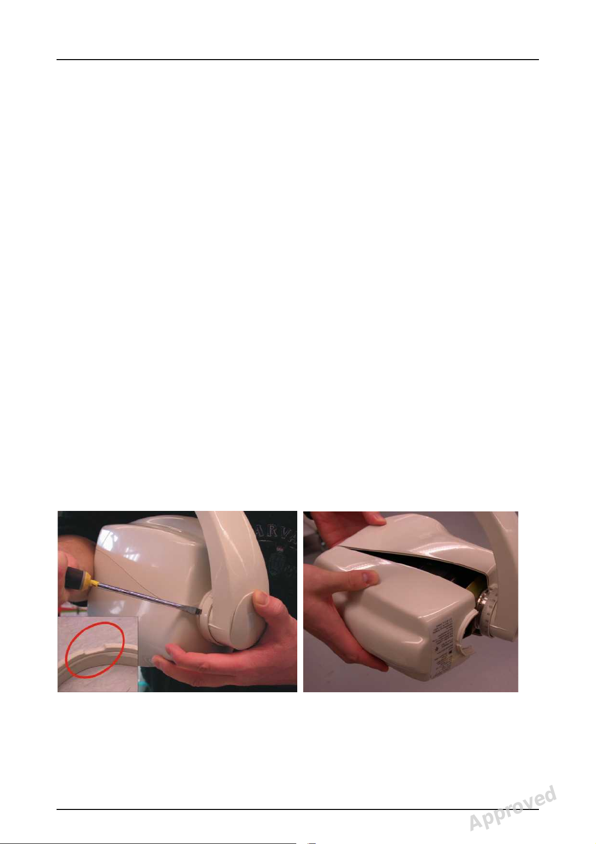
2.
Release the angle ring with a screwdriver and remove
the back cover.
208659 rev 1 Instrumentarium Dental 1
Reviewed: Anttila Mika Johannes 2012-03-14 16:42
Approved: Lehtinen Matti 2012-03-16 10:17
See PDM system to determine the status of this document. Printed out: 2015-04-09 09:41:14
Copyright © 2012 by PaloDEx Group Oy. All rights reserved.
D508755, 1
Approved
1 Changing the tube head
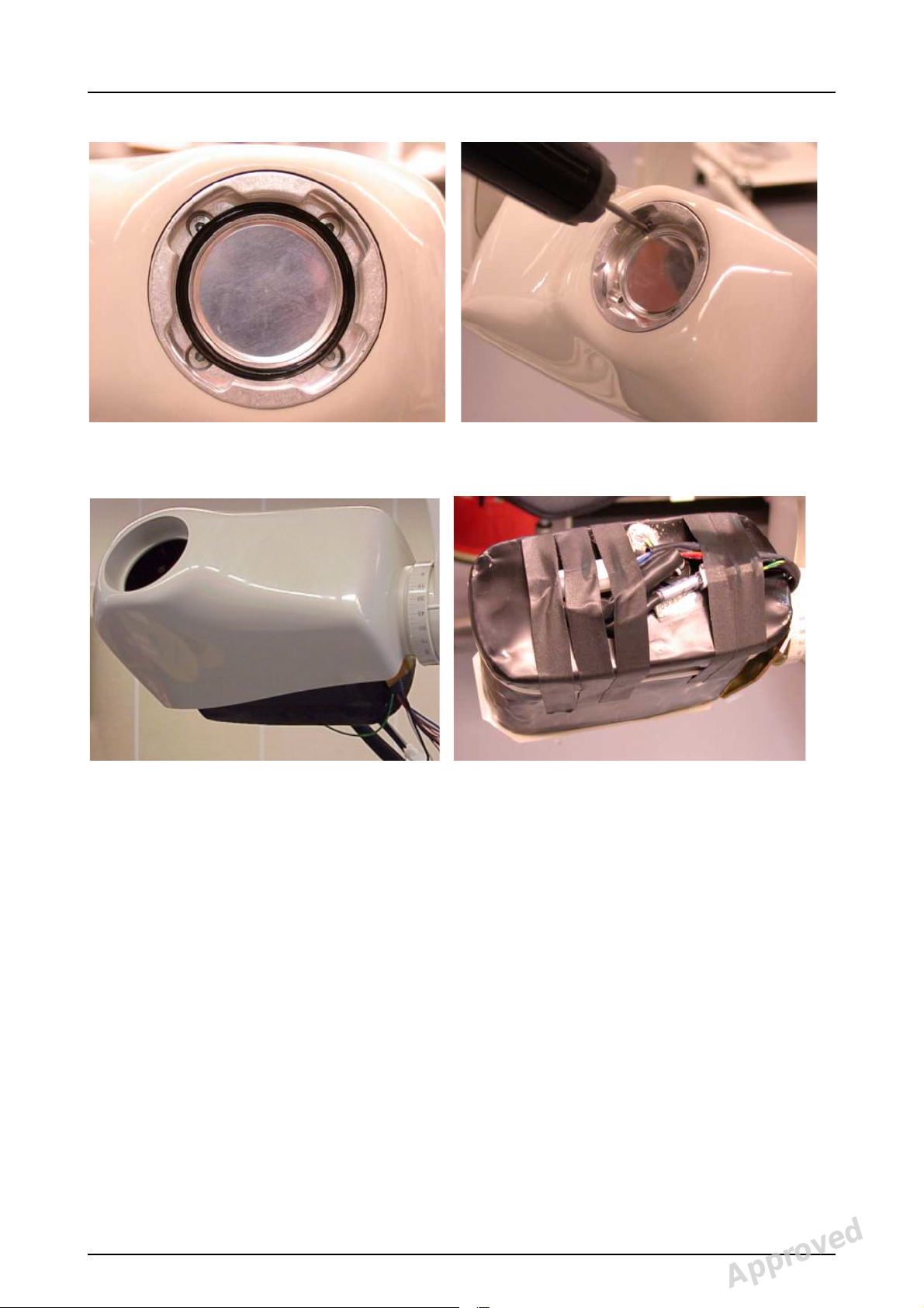
3.
Remove the O-ri ng and the aluminum filter.
4.
Remove the tube heads front cover, cable tie and
tapes.
5.
Detach the Molex connectors and ground cable from
tube head. Disengage the bottom screws from the
locking plates and remove the screws.
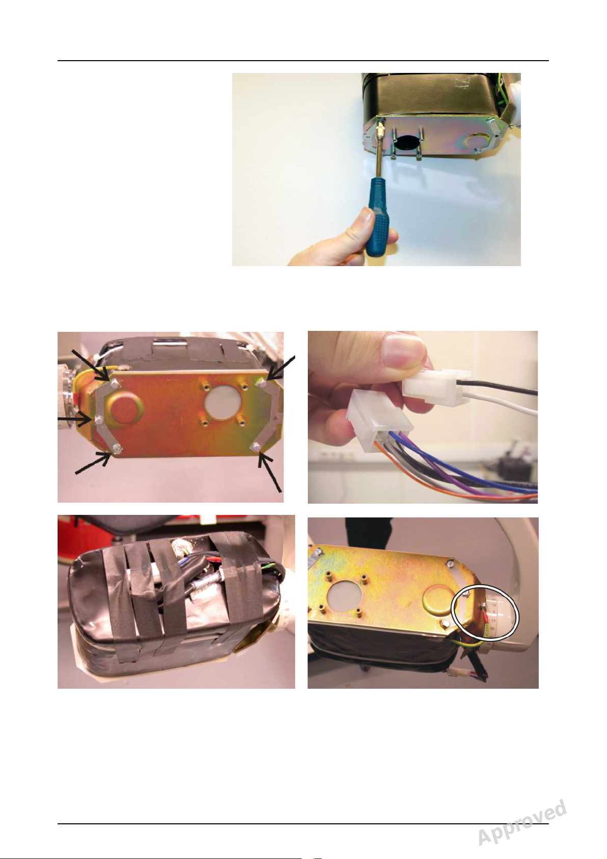
6.
Replace the tube head with new one. Remember to
put the mylar coat between the bracket and the tube
head. Set the locking plates on the bottom of the
bracket and tighten the screws with 0.5 Nm torque.
Use torque wrench. If the torque wrench is not
available use the similar tool like in the picture, and
tight the screws using only two fingers. Do not use any
glues. Fix the locking plates around the bottom
screws.
2 Instrumentarium Dental 208659 rev 1
Reviewed: Anttila Mika Johannes 2012-03-14 16:42
Approved: Lehtinen Matti 2012-03-16 10:17
See PDM system to determine the status of this document. Printed out: 2015-04-09 09:41:14
Copyright © 2012 by PaloDEx Group Oy. All rights reserved.
D508755, 1
Approved
1 Changing the tube head
CAUTION!
Excessive tightening may damage the tube head.
7.
Connect the molex connectors and screw down the
ground cable. Screw down the ground cable to the
tube head bracket.
8.
Bind the cables a roun d the tube head with cable cl amp
and tape.
208659 rev 1 Instrumentarium Dental 3
Reviewed: Anttila Mika Johannes 2012-03-14 16:42
Approved: Lehtinen Matti 2012-03-16 10:17
See PDM system to determine the status of this document. Printed out: 2015-04-09 09:41:14
Copyright © 2012 by PaloDEx Group Oy. All rights reserved.
D508755, 1
Approved
1 Changing the tube head
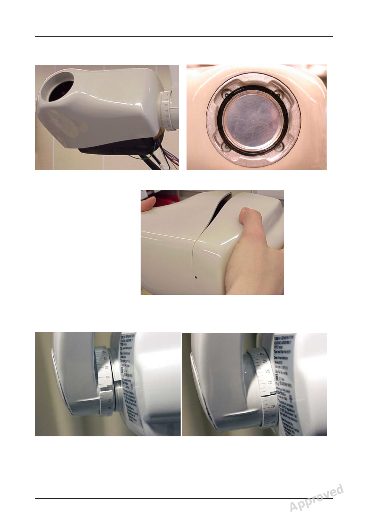
9.
Attach the front cover and aluminum filter to the tube
head. Set the O-ring in to the filter.
10.
Put the back cover back in place.
11.
Fasten the angle ring so that the nodules of the angle
ring will meet the hole in the cover. Turn the ring step
by step and wedge it with a screwdriver.
NOTE! After installation, calibrate the unit.
See chapter Calibration procedure of the un it.
4 Instrumentarium Dental 208659 rev 1
Reviewed: Anttila Mika Johannes 2012-03-14 16:42
Approved: Lehtinen Matti 2012-03-16 10:17
See PDM system to determine the status of this document. Printed out: 2015-04-09 09:41:14
Copyright © 2012 by PaloDEx Group Oy. All rights reserved.
D508755, 1
Approved
1.1.1 Reset the exposure counter, Sr 3
Each unit has the co unter which coun ts the number of the
exposures. The counter should be reset if the tube head
has been changed. Enter the service mode.
Scroll with the arrow keys until “Sr3” appears on the
display.
Press kV button to reset the exposure counter when the
tube head has been changed. The unit beeps twice when
the counter is reseted.
1.2 FOCUS™ 2.0
1.2.1 Changing the tube head (v1.6 and 2.0)
Tube head version 1.6 can be replaced with version 1.6
and version 2.0 or higher can be replaced with version 2.0
or higher.
1 Changing the tube head
NOTE! Version 2.0 does not fit to units with tube head
versions 1.3 to 1.6 be caus e of t he di ffere nce be twee n ma in
cables. Tube he ad versi on 2.0 with new sciss or arm (mai n
cable) does not fit with old horizontal arm with generator
board version 1.2.
1.
Switch off the unit and disconnect from the main.
2.
Release the angle ring with a screwdriver (size
1.2x6.5x125) and remove the back cover.
3.
Remove the O-ri ng and the aluminum filter.
208659 rev 1 Instrumentarium Dental 5
Reviewed: Anttila Mika Johannes 2012-03-14 16:42
Approved: Lehtinen Matti 2012-03-16 10:17
See PDM system to determine the status of this document. Printed out: 2015-04-09 09:41:14
Copyright © 2012 by PaloDEx Group Oy. All rights reserved.
D508755, 1
Approved
 Loading...