

Instrumentarium Dental Focus Intraoral Service manual

ENGLISH
Focus
Service Manual
51714-IMG rev. 2


Copyright
Code: 51714-IMG rev 2 Date: 28 May 2012
Document code: 51714-IMG1TPH-1 rev 2
Copyright © 05/2012 by PaloDEx Group Oy.
All rights reserved.
FOCUS® is a registered trademark of Instrumentarium Dental.
Windows
States of America and other countries.
Documentation, trademark and the software are copyrighted
with all rights reserved. Under the copyright laws the
documentation may not be copied, photocopied, reproduced,
translated, or reduced to any electronic medium or machine
readable form in whole or part, without the prior written
permission of Instrumentarium Dental .
The original language of this manual is English.
Instrumentarium Dental reserves the right to make changes in
specification and features shown herein, or discontinue the
product described at any time without notice or obligation.
Contact your Instrumentarium Dent al repr esent ativ e fo r the most
current information.
®
is trademark of Microsoft Corporation in the United
Manufactured by
Instrumentarium De nta l , Pal oDEx Gr oup Oy
Nahkelantie 160 (P.O. Box 20)
FI-04300 Tuusula
FINLAND
Tel. +358 10 270 2000
Fax. +358 9 851 4048
For service, contact your local distributor.


Table of Contents
1 Introduction..................................................................................................................1
1.1 FOCUS™ intraoral X-ray unit................................................................................1
1.2 Scope....................................................................................................................1
1.3 Associated documentation....................................................................................2
1.4 Servicing warnings and precautions.....................................................................2
2 Error messages and troubleshooting...................... ..... .... ..... ..... ...............................7
2.1 Error messages............................ .... ..... ................................................................7
3 Service mode...............................................................................................................9
3.1 FOCUS™ 2.0........................................................................................................9
3.1.1 Entering the service mode.........................................................................9
3.1.2 Error log, Sr 1........................ ..... ..... ...........................................................9
3.1.3 Reset error log, Sr 2...................................................................................9
3.1.4 Reset the exposure counter, Sr 3 ..............................................................9
3.1.5 Show tube type, Sr 4................................................................................10
3.1.6 Calibration procedure of the unit..............................................................10
3.1.6.1 Calibration .................................................................................10
3.1.6.2 Calibration of AEC, Sr 6.............................................................11
3.1.7 After the service................................................ .......................................12
3.2 FOCUS™ 3.0......................................................................................................13
3.2.1 Entering the service programs.................................................................13
3.2.2 Service programs.....................................................................................15
4 Upgrading the firmware............................................................................................19
4.1 FOCUS™ 2.0......................................................................................................19
4.2 FOCUS™ 3.0......................................................................................................20
5 Changing the generator board.................................................................................23
5.1 FOCUS™ 2.0......................................................................................................23
5.1.1 Old units, before s/n F1243......................................................................23
5.1.2 Later units, after s/n F1243......................................................................23
5.2 FOCUS™ 3.0......................................................................................................25
6 Changing the horizontal arm....................................................................................27
6.1 Removing the arm...............................................................................................2 7
6.2 Attaching the arm................................................................................................27
6.3 Leveling the arm.................................... ..... .........................................................28
7 Changing the tube head............................................................................................29
7.1 FOCUS™ 2.0......................................................................................................29
7.1.1 Changing the tube head (v1.6 and 2.0)....................................................29
7.1.2 Upgrading the tube head (V1.3 -1.5) t o 1.6......................................... ..... .32
7.1.3 Reset the exposure counter, Sr 3 ............................................................38
7.2 FOCUS™ 3.0 (tubehead v3.0)............................................................................39
7.2.1 Reset the exposure counter, Sr 3 ............................................................43
51714-IMG rev 2 Instrumentarium Dental i

8 Changing the voltage................................................................................................45
8.1 FOCUS™ 2.0......................................................................................................45
8.1.1 Changing of the external fuses ................................................................46
8.2 FOCUS™ 3.0......................................................................................................47
8.2.1 Mains voltage:..........................................................................................47
9 Setting the show mode .............................................................................................49
9.1 FOCUS™ 2.0......................................................................................................49
9.2 FOCUS™ 3.0......................................................................................................50
10 After the service.........................................................................................................51
10.1 FOCUS™ 2.0......................................................................................................51
10.2 FOCUS™ 3.0......................................................................................................51
ii Instrumentarium Dental 51714-IMG rev 2

1 Introduction
1.1 FOCUS™ intraoral X-ray unit
1 Introduction
FOCUS™ is a micro processor controlled intraoral X-ray
unit with a HF DC generator, which produces high quality
dental images with film or digital receptors.
A well balanced support arm is easy to move and very
stable, keeping the unit motionless during the exposure.
This manual supports two FOCUS™ intraoral X-ray major
design revisions, namely version 2.0 and version 3.0. See
the correct chapter of the manual for each revision in a
case they differ. Note, that spare parts should also be
ordered accordingly.
The correct design revision can be recognized from the
serial number of the X-ray device as follows:
Version serial number
FOCUS™ 2.0 5000 – 7999
FOCUS™ 3.0 8000 –
1.2 Scope
This document supplements User Manual and Installation
manual for servicing the X-ray unit. This is not a standalone manual. Refer the Associated documentation to
operate and to install the X-ray unit.
Only a trained and authorized service personnel are
allowed to service the unit.
Disclaimer
Instrumentarium Dental endeavors to produce product
documentation that is accurate and up to date. However,
our policy of continual product development may result in
changes to products that are not reflected in the product
documentation. Therefore this document should be
regarded as an infallible guide to current product
specifications.
Instrumentarium Dental maintains the right to make
changes and alterations without a prior notice.
51714-IMG rev 2 Instrumentarium Dental 1

1 Introduction
1.3 Associated documentation
51774 FOCUS™ user manual (t ranslations available)
51775 FOCUS™ Installation manual
208643 FOCUS™ Spare parts cataloque
1.4 Servicing warnings and precautio ns
General precautions
The FOCUS™ intraoral x-ray unit must only be
serviced and repaired by service personnel who have
been trained and approved by Instrumentarium Dental.
This manual is an aid to servicing the units and is NOT
a substitute for approved Instrumentarium Dental
service training.
Before attempting to service a unit make sure that you
know how to operate the FOCUS™. Read the
FOCUS™ user's manual.
Only use original Instrumentarium Dental spare parts
when repairing the unit or replacing parts.
Radiation Safety
Before servicing the unit familiarize yourself with local
and national radiation safety standards and
requirements relating to dental x-ray equipment.
If you need to take test exposures you MUST take
adequate ste ps to prot ect you rself from radiatio n. Use
a lead apron or stand behind a suitable radiation
shield.
In addition, when taking exposures stand at least two
meters (six feet) from the FOCUS™.
Mechanical safety
Switch the power off and disconnect the unit from the
main power supply before removing any covers.
Disconnect the unit from the main power supply before
repairing or replacing mechanical parts.
Be ca re ful w he n h and l i ng t he unit not to get body pa rt s
or clothing trapped between the articulated arm.
When replacing the tube head handle the articulated
are carefully as it will move suddenly when the tube
head is removed.
2 Instrumentarium Dental 51714-IMG rev 2

1 Introduction
Electrical Safety
Switch the power off and disconnect the unit from the
main power supply before replacing circuit boards or
other electrical components. If there are capacitors on
a circuit board or electrical component wait ten (10)
minutes, after disconnecting the unit from the power
supply, before handling the board or component.
Live electrical terminals are potentially dangerous.
Make sure that main power supply is OFF before
removing covers or circuit boards.
This equipment should be used only in areas that ar e
provided with a pr otective earth connec tion to ensure
an equipotential ground connection.
Before cleaning or disinfecting the unit switch the main
power supply off.
Electrostatic discharge
Electrostatic Discharge (ESD) can damage or destroy
electronic components.
A static electricity charge builds up in everyone. The
build up is due to movement, humidity, the person's
clothing and the conductivity of the floor. If anyone
charged with static electricity touches a electronic
component the static electricity will discharge through
the component and can damage or destroy it. Note
that components damaged by electrostatic discharge
can fail at a later date.
When servicing the unit take proper precautions to
avoid electrostatic build up and discharge (ESD).
Follow the recommendations for the prevention of ESD
that are used in the country in which you are working.
If no recommendations are availa ble follow the guide
lines below.
Before handling any electrical parts or components
make sure that any static electricity charge that has
built up in you bod y is discharged.
When handling electrical parts or components use an
elasticated wrist wrap which is conne cted to a ground
point through a 1 Mohm current limiting cable. For a
ground point use water pipes, radiators or other
51714-IMG rev 2 Instrumentarium Dental 3

1 Introduction
objects that are known to be connected to the grou nd .
Also use a cable to connect the unit to the same
ground potential as the wrist wrap.
If an antistatic mat is used, connect the wrist wrap to
the carpet and the carpet to the ground potential.
Wash the wrist wrap and check that it is good condition
frequently.
Explosion Hazard
Certain disinfectants and cleaning agents may
vaporize to form an explosive vapour. If such
chemicals are used the vapour should be allowed to
disperse before sw itching the unit on.
Operating warnings and precautions
The FOCUSTM intraoral x-ray must only be used to
take intraoral exposures. It must not be used for any
other purpose.
The unit or its accessories must not be modified,
altered or remanu factured in any way . Repairing shall
be performed by Instrumentarium Dental authorized
service only.
As radiation safety and protection requirements vary
from country to country and state to state it is the
responsibility of the operator to ensure that all local
and national radiation safety and protection
requirements are met.
The use of ACCESSORY equipment not complying
with the equivalent safety requirements of this
equipment may lead to a reduced level of safety of the
resulting system. Consideration relating to the choice
shall include:
- use of the accessory in the PATIENT VICINITY
- evidence that the safety certification of the
ACCESSORY has been performed in accordance to
the appropriate IEC 601-1 or IEC 950 and/or IEC
601-1-1 harmonized national standard.
4 Instrumentarium Dental 51714-IMG rev 2

1 Introduction
Unauthorized Modifications
Unauthorized changes or modifications to any part of
the unit or its equipment can have hazardous
consequences.
Changes or modifications must not be made unless
specifically authorized by Instrumentarium Dental.
When properly assembled with a compatible
beamlimiting device, the diagnostic source assembly
will fully meet the United States of America Federal
Performance Standards for Diagnostic X-Ray Systems
and their Comp on ents (2 1 CFR 1020 .30-. 32) p rov ided
no components or pa r ts ar e r e mo ved from the unit and
no unauthorized adjustments are made to the beamlimiting device or tube housing assembly.
Never remove or remanufacture any part of the tube
head assembly or beam-limiting device unless under
the direction of Instrumentarium Dental or their
authorized distributor.
Never adjust any part of the beam-limiting device
unless under the direction of Instrumentarium Dental
or their authori zed distributor.
Disposal
At the end of the useful working life of the equipment
and/or its accessories make sure that you follow
national and loca l r egu l atio ns r eg ar din g the disposal of
the equipment, its accessories, par ts and mater ial s.
The equipment includes some or all of the following
parts that are made of or include materials that are
non-environmentally friendly or hazardous:
- x-ray tube head (Pb, Be and mineral oil)
- all electronic circuit boards
Disclaimer
Instrumentarium Dental shall have no liability for
consequential damages, pe rso na l inju ry, loss, da m age
or expense directly or indirectly arising from the use of
its products.
No agent, distributor or other party is authorized to
make any warranty or other liability on behalf of
Instrumentarium Dental with respect to its products.
51714-IMG rev 2 Instrumentarium Dental 5

1 Introduction
6 Instrumentarium Dental 51714-IMG rev 2

2 Error messages and troubleshooting
2 Error messages and troubleshooting
2.1 Error messages
The error messages are grouped into two categories: User
errors (H) and system fault errors (E). User errors must
either be acknowledged or it will be removed once the error
is corrected. When system faults occur, a service
technician should be contacted.
Code Error or
Failure
E1 KV failure Check the fuses.
E2 MA failure Check the fuses.
E3 PREH
failure
E4 Tube head
too hot or
too cold
E5 DC voltage
out of range
Action
Check the cable connections.
Check LA1 light on the
generator board:
ON -> Change the tube head
OFF -> Change the generator
module.
Check the cable connections.
Switch off and on the unit and
calibrate it.
Change the tube head.
Check the cable connections.
Switch off and on the unit and
calibrate it.
Change the generator module.
Wait for valid tube head
temperature
Check the line voltage.
Change the generator module.
E6 Sigma link
error or
sensor not
ready
E7 EEPROM
failure
Necessary
waiting time
H2
Note: H2
flashes
alternately
with elaps ed
exposure
time
51714-IMG rev 2 Instrumentarium Dental 7
Duty cycle Wait for tube to cool
Premature
button
release
Check Sigma-FOCUS™
interface cable and cable
connections
1) Reset parameters (kV+D)
2) Change CPU
Acknowledge with UP or
DOWN button
2 Error messages and troubleshooting
1
1
Code Error or
Failure
H3 Door swit ch
error: door
open. When
a door
switch is
connected
to the
connection
box.
H4 Door swit ch
error: door
open. When
a door
switch is
connected
to the
remote
control.
H5 System in
Service
mode
Action
In case a door switch is in use,
close the door to enable
exposure. Otherw i se check
that the dipswitch no.1 is in onposition on the connection box
board.
In case a door switch is in use,
close the door to enable
exposure. Otherw i se check
that the dipswitch no.2 is in onposition on the remote control
board.
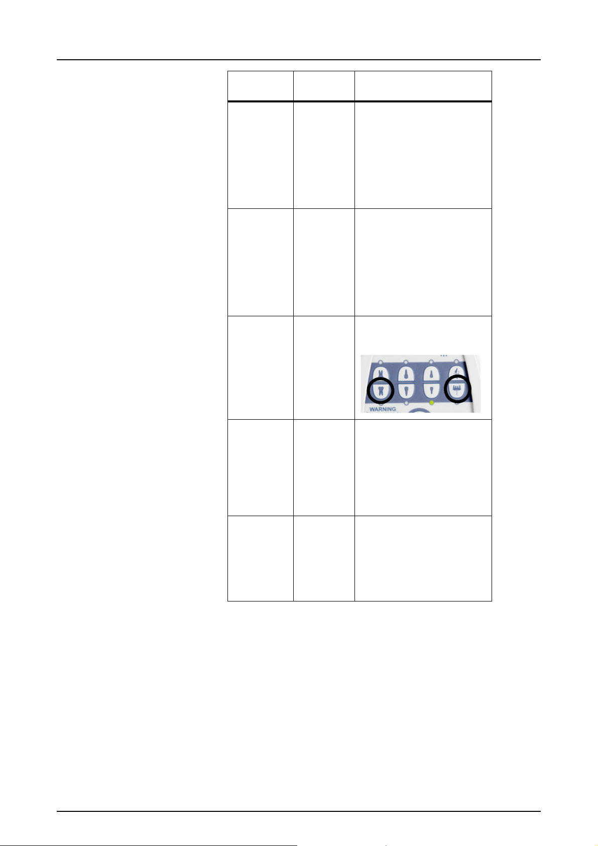
Go to the user mode by
pressing two buttons
simultaneously (1).
H6 Current
Sigma
clocking
mode and
resolution
selection do
not support
AEC.
H7 Exposure
out of
range,
exposure
cancelled.
(in AEC
mode)
Change resolution mode to
minimum dose in CliniView.
This error message may
appear only with CliniView 3.0
or earlier.
Too much attenuat ion between
the sensor and the tu be. Check
that tube head and sensor are
correctly aligned.
8 Instrumentarium Dental 51714-IMG rev 2

3 Service mode
3.1 FOCUS™ 2.0
3.1.1 Entering the service mode
Set the CPU board´s Serv switch to the ON position.
Press the D button on the remote control at least two
seconds until “Sr1” appears on the display.
3 Service mode
Scroll with the arrow keys until the right service code
appears on the display.
3.1.2 Error log, Sr 1
Press kV button to get in Sr1.
You can view last ten error/multification messages by
browsing with arrow keys.
3.1.3 Reset error log, Sr 2
Press kV button when “Sr 2” is selected in order to clear
error log.
3.1.4 Reset the exposure counter, Sr 3
Each unit has the co unter which coun ts the number of the
exposures. The counter should be reset if the tube head
has been changed. Enter the service mode.
Scroll with the arrow keys until “Sr3” appears on the
display.
Press kV button. The uni t beeps twi ce when the counter is
reset.
51714-IMG rev 2 Instrumentarium Dental 9
3 Service mode
3.1.5 Show tube type, Sr 4
Scroll with arrow keys until “sr 4” appears on the display.
Press kV button to enter the program. Tube type is shown
on the screen.
3.1.6 Calibration procedure of the unit
3.1.6.1 Calibration
The unit must be calibrated always after the tube head,
CPU board, EPR OM microchip or the voltag e setting has
been changed. By calibration the tube current and preheat
are adjusted into the limits.
The calibration is performed with the nominal voltage (115
V or 230 V).
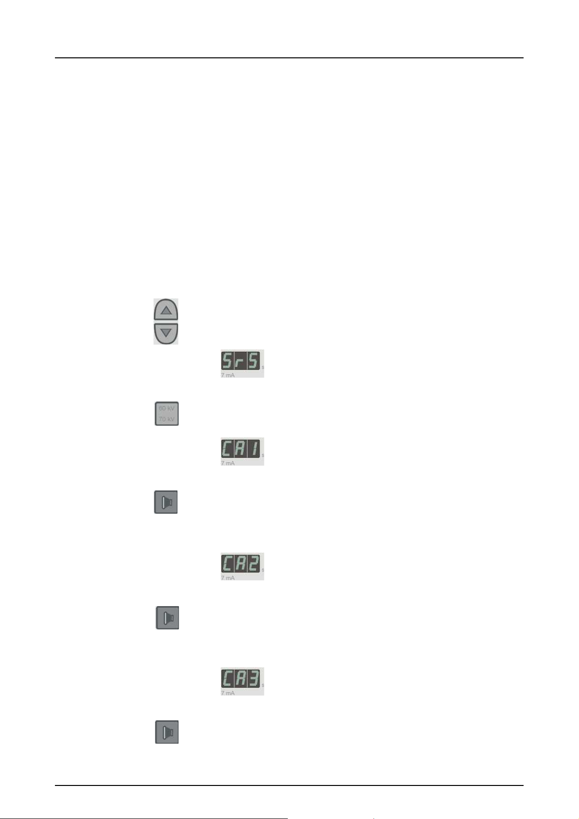
Scroll with the arrow keys until the “Sr5” appears on the
display.
Press the kV button once until “Ca1” appears on the
display. Unit is ready for tube current (7mA) calibration.
Press the exposure button until the unit beeps twice and
“Ca2” appears on the display. You may need to press the
exposure button several times until the calibration is
succeeded.
Unit is ready for 60kV preheat calibration.
Press the exposure button until the unit beeps twice and
“Ca3” appears on the display. You may need to press the
exposure button several times until the calibration is
succeeded.
Unit is ready for 70 kV preheat calibration.
Press the exposure button until the unit beeps three times
and “Sr5” appears on the display. You may need to press
the exposure button several times until the calibration is
succeeded.
10 Instrumentarium Dental 51714-IMG rev 2

3 Service mode
The unit is now calibrated.
3.1.6.2 Calibration of AEC, Sr 6
NOTE! This service program is used in units from s/n 2141
and in units with FOCUS™ AEC kit installed.
In this service program you can calibrate AEC. The
calibration affects the exposure level that is shown with the
image information. The exposure level must be between
80% and 100% for a correctly working AEC and optimum
image. If the level is not w ithin th e rang e, you can adjust so
called multiplier and offset value to correct the exposure
level.
Multiplier is a vari able in the exposure time formula of the
AEC. Multiplier alternatives are 7/5, 7/4, 2/1, 7/3, 5/2, 3/1,
7/2 and 4/1. Increasing the multiplier raises the exposure
level and decreasi ng of the multiplier lowers the exposure
level.
However, in case of small attenuation, for instance a
bitewing image of a toothless patient, AEC would produce
too low exposure levels (<80%) if only mu ltiplier valu e was
adjusted. Then also the offset value is needed to be set.
Offset value is a fixed amount of time that is added to every
AEC exposure. Offset alternatives are 0, 1, 2, 3, 4, 5, 6, 7,
8, 9 and 10 milli-seconds.
Before entering program Sr6, put AEC on and make an
exposure of a 10 mm thick Al-plate (or any attenuation that
is 10 mm Al eqvivalent) and another exposure without
anything but air between sensor and cone of FOCUS™.
Both exposu res with A EC, 60 kV and as sh ort distan ce as
possible between the Sigma sensor and cone of
FOCUS™. Check the exposure level perce ntage from the
image information of both images. If it is not between 80%
and 100% in either image, adjust multiplier and/or offset as
follows.
Multiplier
1.
Enter the service p rogra m mode by settin g the serv ice
switch to ON position. Scroll with the arrow keys untill
the “Sr6” appears on the display. Press the kV button
to enter the program.. Scroll with the arrow keys unt il
the “Sr6” appears on the display. Press the kV button
to enter the program.
2.
You can scroll through the multipliers with arrow keys.
Choose the multiplier.
51714-IMG rev 2 Instrumentarium Dental 11

3 Service mode
3.
Enter the user program mode by setting the service
switch to OFF position. Select 60 kV, check that AEC
is on (led next to AEC button is illuminating) and make
an exposure of the Al-plate.
4.
Check the exposure level from the image information
dialogue.
5.
Make another adjustment if necessary (enter the
service program mode etc.)
Offset
1.
Enter the service p rogra m mode by settin g the serv ice
switch to ON position. Scroll with the arrow keys until
the “Sr6” appears on the dispaly. Press the kV button
to enter the program which is dispayed as fraction.
2.
Press the patient button to enter the offset level.
3.
Select the offset value by scrolling with arrow keys.
4.
Enter the user program mode by setting service switch
to OFF position. Select 60 kV, check that AEC is on
(led next to AEC button is illuminating) and make
exposure without anything but air between the se nsor
and the cone of FOCUS™.
5.
Check the exposure level from the image information
dialogue.
6.
Make another adjustment if necessary (enter the
service program mode etc.).
3.1.7 After the service
1.
Exit service program by pressing the D button until the
exposure time appears on the display.
2.
Set the service and test switches off.
3.
Lift the electronics. It is easier to slide the cables back
in if you remove the horizontal arm cap near the wall
mounting and pull gently the cables by your hand from
the end of the arm.
NOTE! Do not pinch the wires between the horizontal arm
and the bottom p l ate while lifting the electronics board.
4.
Make one test exposure to make sure that the unit
works properly.
12 Instrumentarium Dental 51714-IMG rev 2
 Loading...