

Instrumentarium Dental Express Imaging Plate System Service manual

EXPRESS™ Origo ICR6-1
Digital intraoral imaging plate system
Field Service Manual
Document no. 210586 rev.2
(2014-06)
Reviewed: Klemola Timo 2014-06-19 10:58
Approved: Kyllönen Mika 2014-07-22 11:12
See PDM system to determine the status of this document. Printed out: 2015-04-08 16:23:12
Copyright © 2014 by PaloDEx Group Oy. All rights reserved.
D511515, 2
Approved

EXPRESS™ Origo ICR6-1
Digital intraoral imaging plate system
Field Service Manual
Document no. 210586 rev.2 (2014-06)
Copyright © 06/14 by Instrumentarium Dental.
All rights reserved.
EXPRESS™ is a
common law trademark of Instrumentarium Dental,
PaloDEx Group Oy.
Documentation, trademark and the software are copyrighted with all rights
reserved. Under the copyright laws the documentation may not be copied,
photocopied, reproduced, translated, or reduced to any electronic medium or
machine readable form in whole or part, without the prior written permission of
Instrumentarium Dental.
Manufactured by
Instrumentarium Dental, PaloDEx Group Oy
Nahkelantie 160 (P.O. Box 20)
FI-04300 Tuusula
FINLAND
Tel. +358 10 270 2000
Fax. +358 10 270 2230
EXPRESS™ Origo ICR6-1 Field Service Manual 210586 rev 1 (2014-06) 2 (61)
Reviewed: Klemola Timo 2014-06-19 10:58
Approved: Kyllönen Mika 2014-07-22 11:12
See PDM system to determine the status of this document. Printed out: 2015-04-08 16:23:12
Copyright © 2014 by PaloDEx Group Oy. All rights reserved.
D511515, 2
Approved

TABLE OF CONTENTS
INTRODUCTION .................................................................................................................... 5
DISCLAIMER ........................................................................................................................... 5
SCOPE ..................................................................................................................................... 5
INSTRUCTION / COMMAND SYNTAX USED IN THE MANUAL:........................................................ 5
ACRONYMS USED IN THIS MANUAL .......................................................................................... 5
OPERATING WARNINGS AND PRECAUTIONS .............................................................. 6
SERVICING PRECAUTIONS ........................................................................................................ 6
SYSTEM DESCRIPTION ....................................................................................................... 8
BLOCK DIAGRAM .................................................................................................................... 8
ID EXPRESS ORIGO ASSEMBLY ...................................................................................... 9
SCANNER MECHANISM ASSEMBLY ............................................................................. 10
ELECTRONICS ....................................................................................................................... 12
FIRMWARE ............................................................................................................................ 14
USER INTERFACE STATUSES .......................................................................................... 15
SERVICE TERMINAL ......................................................................................................... 17
ACCESSING SERVICE TERMINAL ............................................................................................ 17
NORMAL AND SERVICE MODE OF THE UNIT ........................................................................... 19
SERVICE COMMAND PRINCIPLES ............................................................................................ 19
SERVICE LOG ........................................................................................................................ 20
CONFIGURATION PARAMETERS ................................................................................... 21
SHOWING / SETTING CONFIGURATION PARAMETERS ................................................................ 21
AUTOSTART <AUTOSCAN> .................................................................................................... 21
BEEPER ................................................................................................................................. 21
ENERGY SAVE MODE <IDLE> ................................................................................................. 21
AUTOMATIC SHUTDOWN <OFF> ............................................................................................. 21
RESTORING FACTORY SETTINGS ............................................................................................. 21
TROUBLESHOOTING ......................................................................................................... 22
ERROR MESSAGES ........................................................................................................... 22
ERROR 1, K100 ..................................................................................................................... 22
ERROR 2, PMT ...................................................................................................................... 23
ERROR 3,LASER .................................................................................................................... 24
ERROR 4, RESONATOR ........................................................................................................... 24
ERROR 12, K200 NOT CONNECTED ......................................................................................... 25
ERROR 13, K300 NOT CONNECTED ......................................................................................... 25
ERROR 23, K200 ................................................................................................................... 26
ERROR 24, LINEAR MOVEMENT ............................................................................................. 27
ERROR 34, PLATE SENSOR ...................................................................................................... 28
ERROR 123, DOOR MOVEMENT ERROR .................................................................................. 28
ERROR 124, SAFETY COVER ................................................................................................... 29
ERROR 234, UI ...................................................................................................................... 30
MAINTENANCE ................................................................................................................... 31
ROUTINE CHECKS WITHOUT OPENING THE UNIT ..................................................... 31
ROUTINE CHECKS WHEN UNIT OPENED: ..................................................................... 31
Plate carrier belt (conveyor belt): .................................................................................... 32
EXPRESS™ Origo ICR6-1 Field Service Manual 210586 rev 1 (2014-06) 3 (61)
Reviewed: Klemola Timo 2014-06-19 10:58
Approved: Kyllönen Mika 2014-07-22 11:12
See PDM system to determine the status of this document. Printed out: 2015-04-08 16:23:12
Copyright © 2014 by PaloDEx Group Oy. All rights reserved.
D511515, 2
Approved

Tension check and adjustment .......................................................................................... 32
INSTRUCTIONS FOR CHANGING SPARE PARTS ........................................................ 34
REMOVING AND INSTALLING THE COVERS ............................................................... 34
COLOR ACCENT PANEL ................................................................................................ 34
BACK COVER .................................................................................................................. 35
FRONT COVER ............................................................................................................... 35
CONTROL PANEL ........................................................................................................... 36
LIGHT COVER ................................................................................................................ 37
REPLACING MOVEMENT KIT PARTS (SP00912) ............................................................... 38
REPLACING OUTER COVERS (SP00989) ............................................................................ 43
REPLACING INNER LIGHT PROTECT COVER (SP00914) ................................................. 43
REPLACING CONTROL PANEL ASSEMBLY (SP00991) .................................................... 43
REPLACING K200 HOME-LASER-DETEC IPS-2013 (SP00916).......................................... 44
REPLACING K300 PLATE DETEC REFL.SEN IPS-2013 (SP00917) .................................... 45
REPLACING LASER AND MIRROR ASSEMBLY IPS-2013 (SP00918) .............................. 46
REPLACING PMT (SP00919) ................................................................................................. 47
REPLACING UNIT DOOR (SP00920) .................................................................................... 47
FIRMWARE AND CORE UPGRADE ................................................................................. 48
FIRMWARE ............................................................................................................................ 48
CORE UPGRADE ..................................................................................................................... 48
TROUBLESHOOTING ......................................................................................................... 49
ERRORS WITHOUT ERROR CODE ............................................................................................. 49
IMAGE ERRORS ...................................................................................................................... 50
Improper use of the hygiene accessories .......................................................................... 50
Improper X-ray settings used ............................................................................................ 50
Ghost images, shadows..................................................................................................... 50
Improper aiming of the X-ray ........................................................................................... 50
Unsharp / blurred images ................................................................................................. 51
Geometry distortion .......................................................................................................... 51
Decreased contrast, shadows/shading, ghost images… ..................................................... 51
White or grey dots/spots/stains in images ......................................................................... 51
Wearing of the imaging plates .......................................................................................... 51
Image shows different size than the IP used ...................................................................... 53
Circle on image ................................................................................................................ 53
Vertical stripe(s) ............................................................................................................... 53
White bar before image .................................................................................................... 54
PMT problems .................................................................................................................. 54
Incorrect dimensions ........................................................................................................ 54
Compressed (too narrow) image ....................................................................................... 54
SPARE PARTS ...................................................................................................................... 55
APPENDIX 1: TEST AFTER REPAIR ................................................................................ 59
APPENDIX 2: ELECTRICAL SAFETY TESTING IN ACCORDANCE WITH THE IEC
62353 STANDARD FOR SCANNER .................................................................................... 60
INTRODUCTION ..................................................................................................................... 60
WARNINGS AND PRECAUTIONS .............................................................................................. 60
VISUAL INSPECTION. ............................................................................................................. 61
EXPRESS™ Origo ICR6-1 Field Service Manual 210586 rev 1 (2014-06) 4 (61)
Reviewed: Klemola Timo 2014-06-19 10:58
Approved: Kyllönen Mika 2014-07-22 11:12
See PDM system to determine the status of this document. Printed out: 2015-04-08 16:23:12
Copyright © 2014 by PaloDEx Group Oy. All rights reserved.
D511515, 2
Approved

INTRODUCTION
Disclaimer
Manufacturer endeavors to produce product documentation that is accurate and up to
date. However, our policy of continual product development may result in changes to
products that are not reflected in the product documentation. Therefore, this document
should not be regarded as an infallible guide to current product specifications.
Manufacturer maintains the right to make changes and alterations without prior notice.
Scope
This manual provides the information necessary to perform field servicing and
maintaining of the EXPRESS™ Origo Digital imaging plate system (hereafter referred
as a ” scanner unit”).
NOTE: THIS MANUAL IS NOT A STAND-ALONE MANUAL AND MUST BE READ
TOGETHER WITH THE USER’S MANUAL
Only trained and approved service personnel of authorized distributors are allowed to
service the unit.
Unit can be sent to manufacturer for repair if it cannot be repaired by:
• Performing the calibrations instructed in this manual AND
• Replacing field serviceable parts
Instruction / command syntax used in the manual:
<text> The text inside the brackets is typed in exactly as instructed + followed by
enter
Example <reset> means typing:reset (and pressing enter)
Example <idle> Show the time unit waits before goes to standby
Example <idle XXX> Sets time (XXX seconds) unit waits before goes to standby
Acronyms used in this manual
ADC Analog to Digital Converter
Cmd Command
DSD driver The device driver used together with an imaging application
EMC Electromagnetic compatibility
EMI Electromagnetic interference
FW Firmware control the scanner unit operation
HV High Voltage
I/O Input/Output
IP Imaging Plate
IP address Internet Protocol Address, typically looks like 192.168.0.2
JXXXX Connector number
Msg Message
NIC Network Interface Card
PMT Photo Multiplier Tube (=Photo detector)
PSU External Power Supply Unit
EXPRESS™ Origo ICR6-1 Field Service Manual 210586 rev 1 (2014-06) 5 (61)
Reviewed: Klemola Timo 2014-06-19 10:58
Approved: Kyllönen Mika 2014-07-22 11:12
See PDM system to determine the status of this document. Printed out: 2015-04-08 16:23:12
Copyright © 2014 by PaloDEx Group Oy. All rights reserved.
D511515, 2
Approved

OPERATING WARNINGS AND PRECAUTIONS
CLASS 1 LASER EQUIPMENT
DANGER: Any failure to follow the recommendations and instructions in this manual
may expose the user to laser radiation exceeding the class 1 specifications.
CAUTION:
• Do not move or knock the scanner when it is scanning.
• The use of control or adjustment or performance of procedures other than those
specified herein may result in hazardous laser radiation exposure.
• This scanner must only be used to read image plates and must not be used for
any other purpose. Only use the imaging plates and protective covers that are
supplied by scanner unit manufacturer. NEVER use imaging plates or protective
covers from other manufacturers with the scanner
• This scanner, or its accessories, must not be modified, altered or
remanufactured in any way.
• Only the manufacturer’s authorized service personnel are authorized to carry out
annual maintenance and repair. There are no user serviceable parts inside.
• This device can interfere with other devices due to its EMC characteristics.
• Other devices can interfere with this device due to their EMC characteristics.
• This device complies with IEC 60601-1 standard. Accessory equipment
connected to this device must be in compliance with the related nationally
harmonized IEC standards.
• Equipment not suitable for use in the presence of flammable anesthetic mixture
with air or with oxygen or nitrous oxide.
• Only use the power supply unit that is supplied with the scanner. Do not use any
other power supply units with the scanner.
• Use RJ45 UTP network cable, CAT 6
• Other cables and accessories may negatively affect EMC
Servicing Precautions
WHEN SERVICING EXPRESS™ ORIGO ALWAYS TURN POWER OFF AND
DETACH POWER SUPPLY AND ETHERNET CONNECTORS BEFORE OPENING
THE COVERS.
DO NOT ATTACH POWER SUPPLY AND ETHERNET CONNECTORS BACK UNTIL
COVERS ARE INSTALLED BACK.
ESD
When servicing & unit covers being open, please note that inside the unit all electrical
components are ESD sensitive. Appropriate protective methods (ESD wristbands, ESD
safe working areas & ESD clothes etc…) must be used against ESD problems.
Laser Radiation
There is a class 3B laser inside the scanner. The laser can be activated if the light
beam in the optic safety switch is blocked and the laser is switched on from the service
terminal. Avoid direct exposure to the laser beam or its’ reflections (for instance from
shiny tools etc).
EXPRESS™ Origo ICR6-1 Field Service Manual 210586 rev 1 (2014-06) 6 (61)
Reviewed: Klemola Timo 2014-06-19 10:58
Approved: Kyllönen Mika 2014-07-22 11:12
See PDM system to determine the status of this document. Printed out: 2015-04-08 16:23:12
Copyright © 2014 by PaloDEx Group Oy. All rights reserved.
D511515, 2
Approved

High Voltage
There is a high voltage circuit between the photo multiplier tube and amplifier card. High
voltage can be set on when the light beam of opto safety switch is blocked. See service
commands.
Light Sensitivity of Photo Multiplier Tube
The tube is very sensitive to light when it is active. Tube is activated when the high
voltage is turned on. The tube is used to measure extremely small amounts of light
Normal room light and brighter light sources damage HV-activated tube.
EXPRESS™ Origo ICR6-1 Field Service Manual 210586 rev 1 (2014-06) 7 (61)
Reviewed: Klemola Timo 2014-06-19 10:58
Approved: Kyllönen Mika 2014-07-22 11:12
See PDM system to determine the status of this document. Printed out: 2015-04-08 16:23:12
Copyright © 2014 by PaloDEx Group Oy. All rights reserved.
D511515, 2
Approved
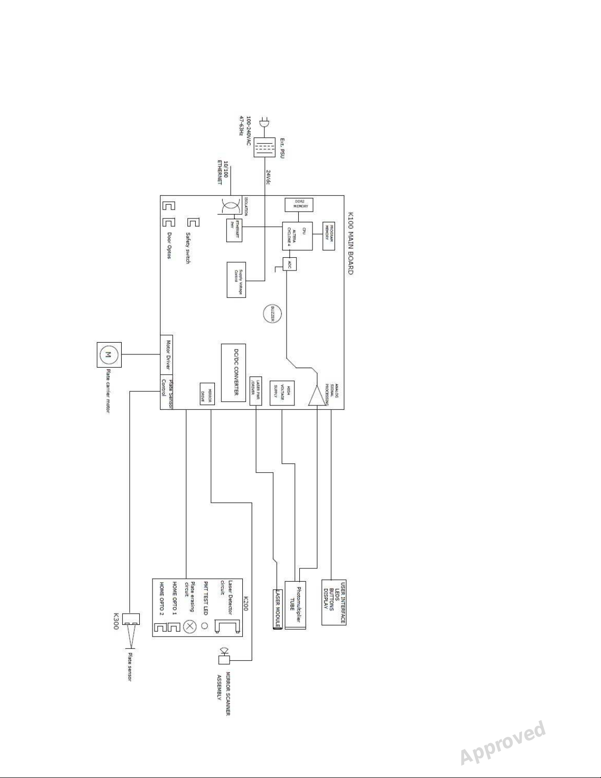
SYSTEM DESCRIPTION
Block diagram
EXPRESS™ Origo ICR6-1 Field Service Manual 210586 rev 1 (2014-06) 8 (61)
Reviewed: Klemola Timo 2014-06-19 10:58
Approved: Kyllönen Mika 2014-07-22 11:12
See PDM system to determine the status of this document. Printed out: 2015-04-08 16:23:12
Copyright © 2014 by PaloDEx Group Oy. All rights reserved.
D511515, 2
Approved
RECYCLING
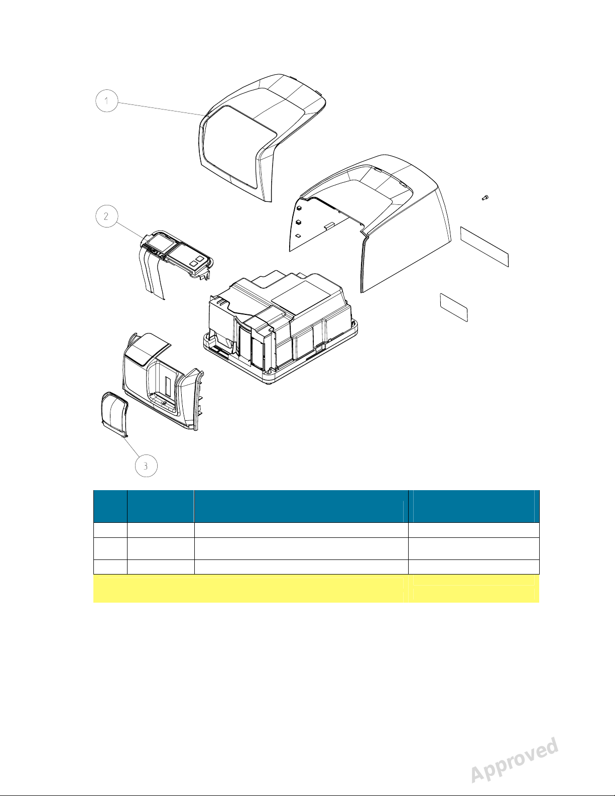
ID EXPRESS ORIGO ASSEMBLY
ITEM CODE
1 SP00989 OUTER COVERS EXPRESS ORIGO
2 SP00991 CONTROL PANEL EXPRESS ORIGO
3 SP00993 IMAGING PLATE COLLECTOR
NOTE!
Products without part numbers are not for sale.
DESCRIPTION
SP00989 OUTER COVERS EXPRESS ORIGO includes:
- 1 pcs SCANNER FRONT COVER
- 1 pcs SCANNER BACK COVER with ICR6 TYPE LABEL and LASER CLASS3B
WARNING LABEL
- 1 pcs ID SCANNER COLOR ACCENT PANEL
- 1 pcs IMAGING PLATE COLLECTOR
- 1 pcs M4X8 DIN85 FEZN
EXPRESS™ Origo ICR6-1 Field Service Manual 210586 rev 1 (2014-06) 9 (61)
Reviewed: Klemola Timo 2014-06-19 10:58
Approved: Kyllönen Mika 2014-07-22 11:12
See PDM system to determine the status of this document. Printed out: 2015-04-08 16:23:12
Copyright © 2014 by PaloDEx Group Oy. All rights reserved.
INFORMATION
MATERIAL
PC+ABS
Frame: PC+ABS
Others: E-scrap
PC+ABS
Approved
D511515, 2
E-SCRAP
PBT/Steel
NOTE!
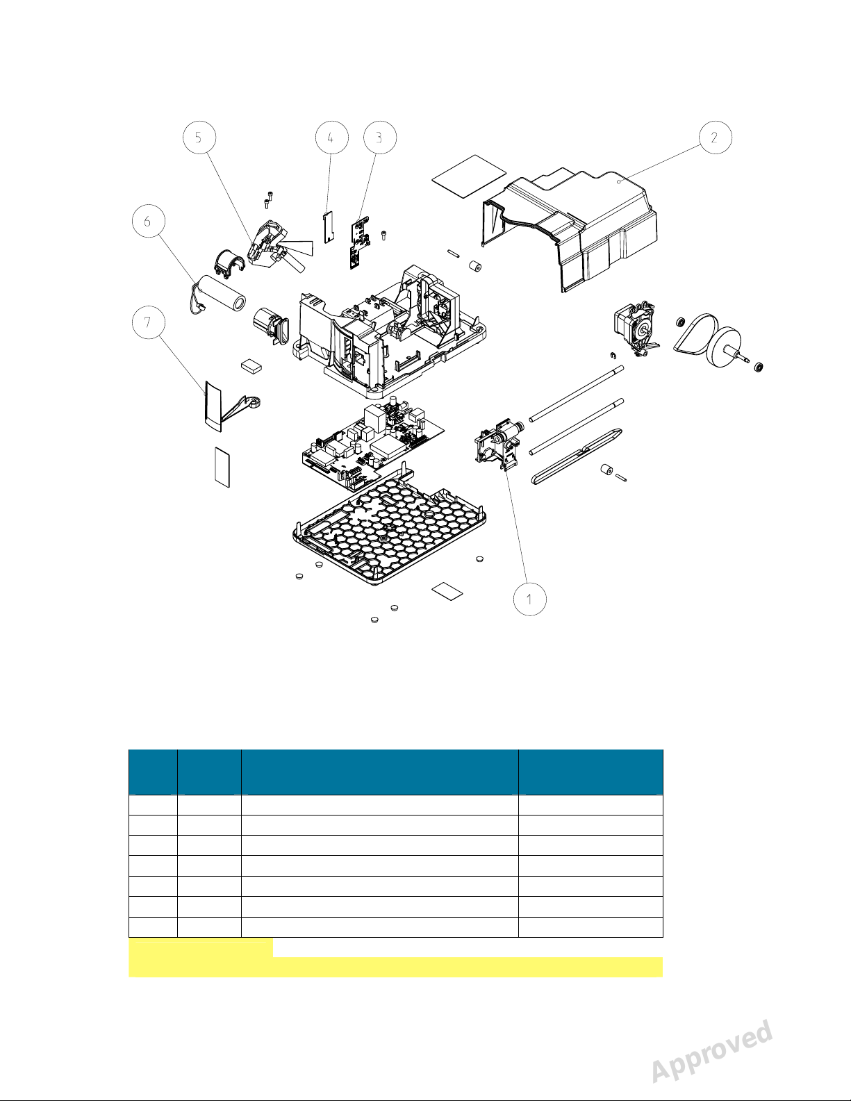
SCANNER MECHANISM ASSEMBLY
ITEM CODE DESCRIPTION
1 SP00912 MOVEMENT KIT IPS-2013
2 SP00914 INNER LIGHT PROTECT COVER IPS-2013
3 SP00916 K200 HOME-ERASE-LASERDETEC IPS-2013
4 SP00917 K300 PLATE DETECT REFL.SEN IPS-2013
5 SP00918 LASER AND MIRROR ASSEMBLY IPS-2013
6 SP00919 PMT, PHOTO MULTIPLIER TUBE IPS-2013
7 SP00920 UNIT DOOR IPS-2013
Products without part numbers are not for sale.
RECYCLING
INFORMATION
MATERIAL
PC+ABS
E-SCRAP
E-SCRAP
E-SCRAP
EXPRESS™ Origo ICR6-1 Field Service Manual 210586 rev 1 (2014-06) 10 (61)
Reviewed: Klemola Timo 2014-06-19 10:58
Approved: Kyllönen Mika 2014-07-22 11:12
See PDM system to determine the status of this document. Printed out: 2015-04-08 16:23:12
Copyright © 2014 by PaloDEx Group Oy. All rights reserved.
D511515, 2
Approved
NdFeB/ Aluminum/
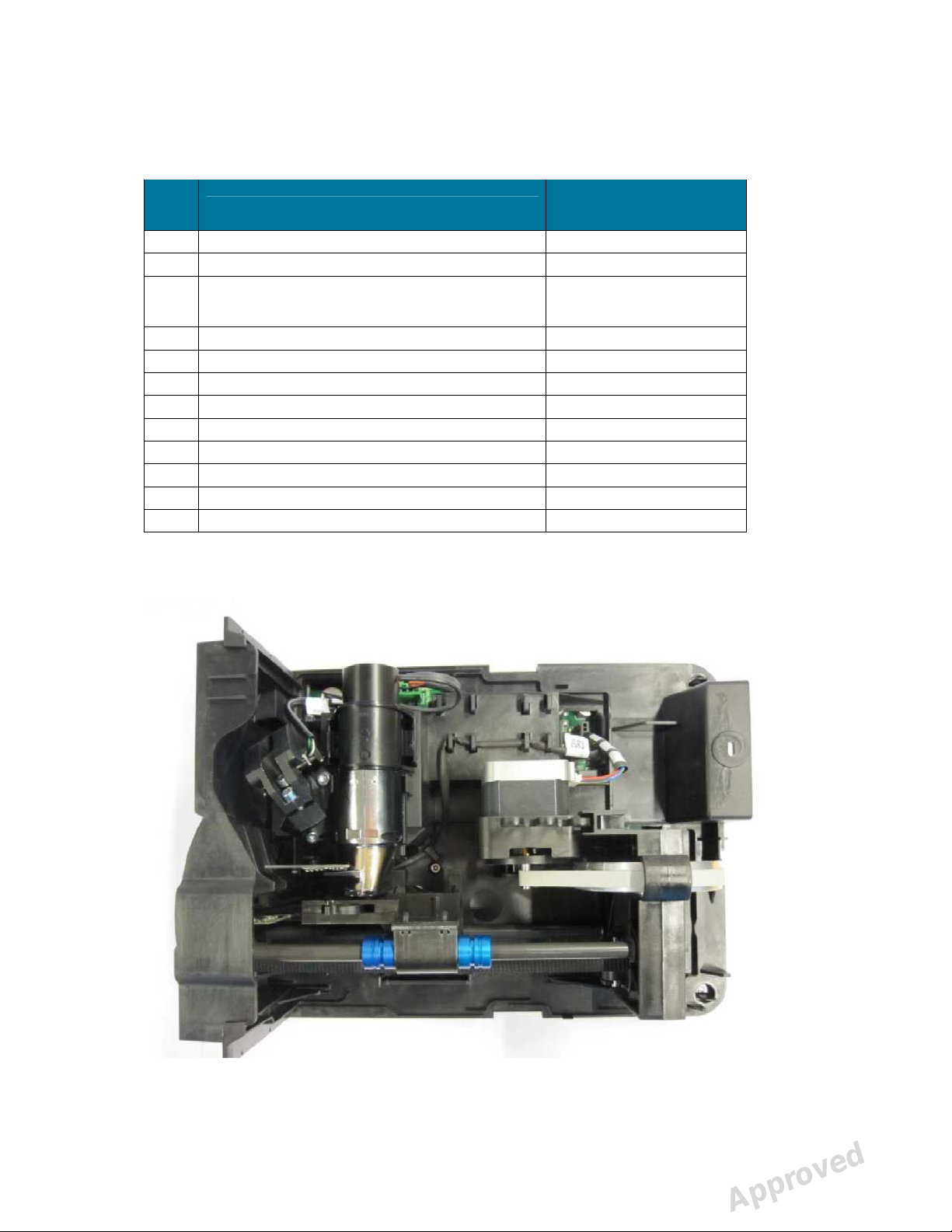
SP00912 MOVEMENT KIT IPS-2013 includes
RECYCLING
INFORMATION
PCS ITEM
2 SHAFT CCM08 CERAMIC COATED Aluminum, ceramic coated
1 BELT PULLEY COVER POM
1 IMAGING PLATE CARRIAGE ASSEMBLY POM/
1 MOTOR HOLDER ASSEMBLY POM/Steel/E-scrap
1 READOUT HEAD BELT MXL025-G Rubber
1 BELT 264X8 CH XL GA152 MANDREL84.1 Rubber
1 BELT PULLEY 73.8 - 5.4 Aluminum
2 BELT PULLEY POM
2 BEARING 625 ZZ Steel
1 DOWEL PIN 4H6X24 DIN6325 Steel
2 LOCKRING 6 DIN6799 Steel
1 NEEDLE ROLLER NRB4X25,8-G2 Steel
MATERIAL
Glass-fiber reinforced
polyarylamide
Covers and control panel assembly removed
EXPRESS™ Origo ICR6-1 Field Service Manual 210586 rev 1 (2014-06) 11 (61)
Reviewed: Klemola Timo 2014-06-19 10:58
Approved: Kyllönen Mika 2014-07-22 11:12
See PDM system to determine the status of this document. Printed out: 2015-04-08 16:23:12
Copyright © 2014 by PaloDEx Group Oy. All rights reserved.
D511515, 2
Approved

Electronics
24VDC from External Power Supply
where supply voltage
Other boards are powered from
all boards must be
External Power Supply Unit
auto switching (100
AC
1.25A / 3
Output connector 2.1mm
No serviceable parts inside.
inside FPGA (incl. Ethernet controller and other logic)
System configuration flash
DDR2
(10M/100M)
(14 bit, AD9245)
START: indicates that input 24V is connected
near DC plug and is connected to back using light pipe
is activity led. D
established link at 100 Mbps. These are connected to the back using light pipe.
Analog signal processing circuitry
ge regulators for all boards & for laser
High voltage power supply for PMT (J106 )
Analog signal from PMT J
Circuitry for checking the high voltage.
to K200, K300 and user interface
ptoswitch D29 p
cover being installed.
ASSEMBLY
Membrane keyboard, which has
See user’s guide for more detailed description of keys and indicator light
K200 ERASE AND LASER DETECTION BOARD
Contains two pin diodes
LEDS for erasing the image plate residual image and control circuit for erasing
Opto switches D14 and D15 for sensing linear movement
is connected to
. This is located
is speed led, it is on when Ethernet PHY has
PMT high voltage
that are used to synchronize laser
Powering of the boards:
• INPUT voltage
Board
•
• For proper operation
• Universal input,
• Most commonly used
• Output 24VDC /
s to internal circuits are made
K100.
attached
-240 VAC / 47-63Hz).
plugs available (EU, US, UK, AU)
0W
K100 Main
•
•
K100 Main Board
• System clock
• CPU
•
• General-purpose
• Ethernet interface
• AD conversion
• Led D27 +12V-
• LED D11
•
• Low volta
•
•
•
• I/O between
• Safety o
without the light
center+ DC plug
Do not open.
-memory
memory
12
113
revents the switching of laser and
CONTROL PANEL
•
leds and control keys on it.
•
• Display and cables.
•
(Q1 and Q2)
movement.
•
•
Reviewed: Klemola Timo 2014-06-19 10:58
Approved: Kyllönen Mika 2014-07-22 11:12
See PDM system to determine the status of this document. Printed out: 2015-04-08 16:23:12
Copyright © 2014 by PaloDEx Group Oy. All rights reserved.
s.
D511515, 2
Approved

• Blue led which can be used to check PMT operation. It’s brightness can be
controlled by CPU
K300 PLATE SENSOR BOARD
• Contains circuits for sensing image plate and that it is correctly inserted. Led
emits light which is reflected from IP to the photodiode receiver.
EXPRESS™ Origo ICR6-1 Field Service Manual 210586 rev 1 (2014-06) 13 (61)
Reviewed: Klemola Timo 2014-06-19 10:58
Approved: Kyllönen Mika 2014-07-22 11:12
See PDM system to determine the status of this document. Printed out: 2015-04-08 16:23:12
Copyright © 2014 by PaloDEx Group Oy. All rights reserved.
D511515, 2
Approved
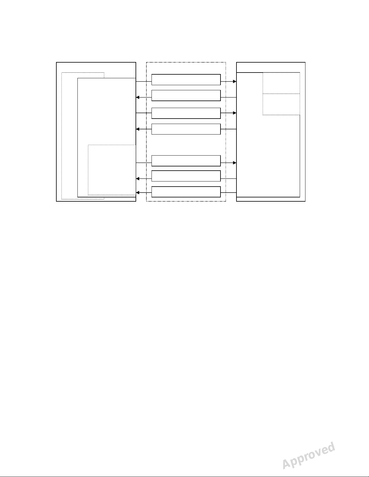
Service Output Msg
Driver Cmd Msg
Image Data Msg
Image Data Request Msg
User Cmd Reply Msg
User Cmd Msg
Driver Cmd Reply Msg
visible to user
Firmware
Architecture
Workstation (PC)
Imaging Application (optional)
Ethernet
Driver
(mandatory)
All messages
invisible to the
user.
Service
Terminal
(optional)
All messages
Imaging Application
• End user’s interface to acquired images.
• Handles image archiving and displaying.
Driver
• Handles the connection/communication to the unit
• Transfers and manipulates images.
• Unit cannot operate without Driver
There are two alternatives to be used as a driver:
1. DSD driver. Run from Application (or other imaging application)
2. s2terminal program. Run from the command prompt of Windows.
Service Terminal
• Optional part of the driver.
• Execute user commands
• View the service output of the unit.
• Run from the command prompt of Windows.
Scanner Firmware and Core
Takes care of the normal unit operations.
• Operates either in normal mode or service mode.
o Normal mode: Unit is fully operational and images can be acquired.
o Service mode: Unit does not react to any other inputs than those given by
the user through service terminal.
The scanner unit
Scanner Firmware and Core
Normal
mode
Service
mode
EXPRESS™ Origo ICR6-1 Field Service Manual 210586 rev 1 (2014-06) 14 (61)
Reviewed: Klemola Timo 2014-06-19 10:58
Approved: Kyllönen Mika 2014-07-22 11:12
See PDM system to determine the status of this document. Printed out: 2015-04-08 16:23:12
Copyright © 2014 by PaloDEx Group Oy. All rights reserved.
D511515, 2
Approved

USER INTERFACE STATUSES
First the user press power button. During boot the system makes initialization and self
test.
1. User presses unit power button
2. Scanner initializes HW
3. Scanner checks that all boards are connected.
4. Scanner IP address configuration is started
5. Scanner drives linear movement to find position where door is closed.
6. Scanner sets linear amplifier offset
7. Check HV
8. Check PMT with blue led
9. Check erase led current and voltage
10. Check mirror resonator operation and stability
11. Check laser
12. Check plate sensor
13. Drive plate carriage out
14. READY for operation (if connection to the application SW is OK)
ERROR CODE is displayed if everything NOT OK during start.
NOTE: if the light protection covers surrounding scanner module is removed
EXPRESS™ Origo goes into error state after erase led test and self test sequence
is halted (recovering from this needs restart of the unit after installing the covers
back)
NOTE! If the opto safety switch light is blocked during start and covers removed –
the PMT may be damaged! Do not turn unit on when the light cover is removed.
Turning off is not possible if image is not transferred to imaging software (for example
Ethernet connection was lost before transfer), unit beeps and blinks PC and connection
leds. The carrier is driven in. The unit will not shutdown automatically. You must start
application and receive image before turning the unit off. You must turn the unit off only
by on/off button.
EXPRESS™ Origo ICR6-1 Field Service Manual 210586 rev 1 (2014-06) 15 (61)
Reviewed: Klemola Timo 2014-06-19 10:58
Approved: Kyllönen Mika 2014-07-22 11:12
See PDM system to determine the status of this document. Printed out: 2015-04-08 16:23:12
Copyright © 2014 by PaloDEx Group Oy. All rights reserved.
D511515, 2
Approved
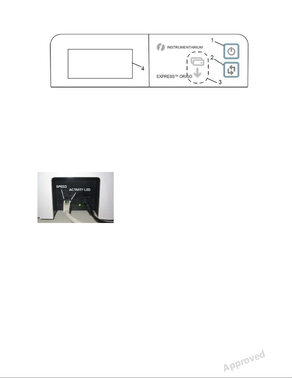
UI PANEL
1. ON/OFF key
2. START key
3. Plate feeding indicator
4. Status display
The use of UI panel display symbols, leds and buttons are described in the user manual.
LEDs backside
The Ethernet speed led is lit when link speed
is established at 100Mhz.
At other speeds the led is off. Activity LED
blinks when the unit sends or receives data
over the Ethernet network.
EXPRESS™ Origo ICR6-1 Field Service Manual 210586 rev 1 (2014-06) 16 (61)
Reviewed: Klemola Timo 2014-06-19 10:58
Approved: Kyllönen Mika 2014-07-22 11:12
See PDM system to determine the status of this document. Printed out: 2015-04-08 16:23:12
Copyright © 2014 by PaloDEx Group Oy. All rights reserved.
D511515, 2
Approved

SERVICE TERMINAL
Service terminal is not an end user interface and training to use it in advance is
mandatory to prevent the changing of unit configuration (=resulting the unit to become
inoperative) accidentally.
Be very careful not to use service commands without the necessary know-how. Gain
knowledge by going through all useful commands and train their usage in practice with
scanner unit.
Service terminal commands and functions are not explained in this manual. They are
instructed in the scanner firmware help (which is accessible through service terminal).
This arrangement is to keep the documentation up to date, since the service terminal
instructions for commands are always up to date in the scanner firmware.
Therefore this manual explains only the principles of the main commands.
More detailed instructions of Service Terminal commands can be found later in this
document and in their help outputs <h [command]>.
Accessing Service Terminal
• Service terminal commands are controlled from s2terminal
NOTE: Only have either imaging application OR s2terminal open at one
time.
• Service commands are executed by scanner unit
• Firmware and core upgrade can only be performed with s2terminal
• s2terminal program is run from the command prompt of Windows.
• Application must be closed when accessing service terminal from s2terminal If
Application is opened at the same time, you will have a “login fail (no
connection)” error message on screen when trying to make the connection.
Note the difference of actual command prompt and the s2terminal program running in it:
• The input and output of the s2terminal and of the command prompt look similar.
• However, the functions and commands available in the command prompt are not
available in the s2terminal and vice versa.
• If you get confused it is good idea to check the title bar of the command prompt
window - it should read “s2terminal” when the s2terminal program is running.
- it reads “cmd.exe” when only Command Prompt is running
• Running the s2terminal program needs the following files:
• s2terminal.exe
• s2.dll
• W32N55.dll
• (s2terminal has to be version 7.7.1188.0 or later)
• S2terminal can be found usually from folder: Program files/Palodex
Group/IAM/
EXPRESS™ Origo ICR6-1 Field Service Manual 210586 rev 1 (2014-06) 17 (61)
Reviewed: Klemola Timo 2014-06-19 10:58
Approved: Kyllönen Mika 2014-07-22 11:12
See PDM system to determine the status of this document. Printed out: 2015-04-08 16:23:12
Copyright © 2014 by PaloDEx Group Oy. All rights reserved.
D511515, 2
Approved

1. Copy all these files to one same and dedicated service folder that you may need
to create (in following example “c:\s2terminal” folder is used to store s2terminal
files)
2. Select from Windows: Start / Programs / Accessories / Command Prompt
Or
Select from Windows: Start / run
3. Type into “Open” -field: <cmd>
4. Choose OK
Command prompt examples:
• <cd\> (Changes to the root directory =C:\)
• <cd s2terminal> (changes to directory “s2terminal”)
5. CHECK THAT Application IS NOT OPENED
6. Type <s2terminal> in the command prompt to see the instructions for the
command syntax. Then execute the program using the unit’s IP -address.
7. Type <s2terminal 192.168.0.2>:
• Starts the Service Terminal for unit having ip 192.168.0.2
Or
Type <s2terminal 192.168.0.2 -c>:
• Starts the service terminal and configures ip –address to scanner unit
192.168.0.2
NOTE: Keep start button pressed when entering <s2terminal 192.168.0.2 –
c>:
8. If the IP-address is correct and the s2terminal program is able to connect to the
unit, it prints out terminal output of the login command, which displays
“s2terminal, the unit’s firmware version(s), serial number and some parameters”.
Otherwise it displays an error message(s).
NOTE: It is normal that you may have few times “login fail (no connection)”
–error also in normal functioning connection
9. Quit s2terminal program by <xq>
EXPRESS™ Origo ICR6-1 Field Service Manual 210586 rev 1 (2014-06) 18 (61)
Reviewed: Klemola Timo 2014-06-19 10:58
Approved: Kyllönen Mika 2014-07-22 11:12
See PDM system to determine the status of this document. Printed out: 2015-04-08 16:23:12
Copyright © 2014 by PaloDEx Group Oy. All rights reserved.
D511515, 2
Approved

Normal and Service Mode of the Unit
Service terminal can be used having scanner unit in Normal mode or Service mode
• Normal mode = Normal operation, use Service terminal to monitor the scanner
unit operation
• Service mode = scanner unit Executes only the commands given from Service
terminal.
Almost all of the service procedures described in this manual are done in the service
mode.
Remember to quit the service mode before trying to use the unit normally.
<s> Activates the service mode – and “service>” prompt is shown in the service
terminal.
NOTE! If scanner unit is in standby mode, the first command only exits the
unit from the standby mode
<quit> Quits the service mode (=resumes scanner into normal operation mode).
<reset> Resets scanner unit. (ONLY SW RESET) Use if you get strange behavior
when trying to use the unit after exiting the service mode. After reset you exit
also the service mode
Service Command principles
General Principles for Command Usage
• About half of the commands activate a function, for instance the movement of
the plate carrier or enabling the laser.
• The other half view or set the configuration parameters of the scanner unit.
• To use commands first see their description by <h [command]>.
>> Then read all of the description before actually using the command.
NOTE: Do not execute the command if you are not sure about it’s function.
Improper use of some commands may result scanner unit to become
inoperative!
• Some commands are used to view and/or set different parameters of the unit.
• When issuing the command without any value (for example <eject>) it will
display the current value of the parameter.
• If the parameter is followed with a value (for example <hv 150>) the parameter
value is changed.
If the unit is in standby mode
• Does not execute the command, exits the energy saving mode when the
command is entered for the first time
>> You have to enter the same command again to perform the required action.
Help Command
EXPRESS™ Origo ICR6-1 Field Service Manual 210586 rev 1 (2014-06) 19 (61)
Reviewed: Klemola Timo 2014-06-19 10:58
Approved: Kyllönen Mika 2014-07-22 11:12
See PDM system to determine the status of this document. Printed out: 2015-04-08 16:23:12
Copyright © 2014 by PaloDEx Group Oy. All rights reserved.
D511515, 2
Approved
 Loading...