

Instrumentarium Dental Express Imaging Plate System Service manual
Express
Service manual
204724 rev.5

204724 rev5 Instrumentarium Dental 2

Copyright Code: 204724 rev 5 Date: 2014-09
Copyright © 2014 by Palodex Group Oy.
All right reserved
Document code: D504667 rev 5
EXPRESS™ is a
common law trademark of Instrumentarium Dental,
Palodex Group Oy.
Manufacturer: Instrumentarium Dental,
Palodex Group Oy
Nahkelantie 160
FI-04300 Tuusula
Finland
Tel. +358 10 270 2000
www.instrumentariumdental.com
204724 rev5 Instrumentarium Dental 3

INTRODUCTION......................................................................................................................... 7
D
ISCLAIMER
S
COPE
I
NSTRUCTION / COMMAND SYNTAX USED IN THE MANUAL
A
CRONYMS USED IN THIS MANUAL
................................................................................................................................. 7
......................................................................................................................................... 7
: ......................................................... 7
.............................................................................................. 7
OPERATING WARNINGS AND PRECAUTIONS ................................................................. 8
S
ERVICING PRECAUTIONS
.......................................................................................................... 8
INSTALLING AND SETTING-UP THE S2TERMINAL ........................................................ 9
R
ECOMMENDED HARDWARE AT INSTALLATION
PRE-
INSTALLATION REQUIREMENTS
EMI –
INTERFERENCE, VIBRATION AND OPERATION WITH
........................................................................................... 9
........................................................................... 9
UPS ................................................. 9
SYSTEM ARCHITECTURE .................................................................................................... 10
B
LOCK DIAGRAM
S
CANNER MECHANICS
E
LECTRONICS
F
IRMWARE
........................................................................................................................ 10
............................................................................................................... 11
........................................................................................................................... 13
................................................................................................................................. 15
UNIT STATUSES AND MODES .............................................................................................. 17
SERVICE TERMINAL .............................................................................................................. 19
A
CCESSING SERVICE TERMINAL
N
ORMAL AND SERVICE MODE OF THE UNIT
S
ERVICE COMMAND PRINCIPLES
S
ERVICE LOG
............................................................................................................................ 22
............................................................................................... 19
............................................................................. 21
.............................................................................................. 21
CONFIGURATION PARAMETERS ....................................................................................... 23
S
HOWING / SETTING CONFIGURATION PARAMETERS
A
UTOSTART <AUTOSCAN
B
EEPER
E
NERGY SAVE MODE <IDLE
P
ROXIMITY SENSOR
A
UTOMATIC SHUTDOWN <OFF
R
ESTORING FACTORY SETTINGS
S
ERVICE COMMANDS ON FIELD SERVICE
..................................................................................................................................... 23
> ........................................................................................................ 23
> .................................................................................................... 23
.................................................................................................................. 23
> ................................................................................................ 23
.............................................................................................. 23
.................................................................................. 24
................................................................ 23
MAINTENANCE ........................................................................................................................ 26
FIELD SERVICE PROCEDURES ........................................................................................... 28
S
ERVICE POLICY
C
ALIBRATING THE REFLECTIVE SENSOR
C
ALIBRATING RESONANT SCANNER AMPLITUDE
G
EAR RATIO CALIBRATION, COMMAND: <GEAR
A
DJUSTING THE PLATE CARRIER (<CALPR POSITION>, <EJECT> AND <START>
: ...................................................................................................................... 28
.................................................................................. 28
..................................................................... 29
> ..................................................................... 29
). ................. 31
FIRMWARE (=FW), CORE AND DISPLAY GRAPHICS UPGRADE .............................. 33
F
IRMWARE
C
ORE UPGRADE
G
RAPHICS FILE UPGRADING
(=FW)
UPGRADE
.................................................................................................... 34
........................................................................................................................ 34
...................................................................................................... 34
CHANGING HARDWARE PARTS ......................................................................................... 35
204724 rev5 Instrumentarium Dental 4

R
EPLACING EXTERNAL POWER SUPPLY
R
EPLACING
R
EPLACING
R
EPLACING
R
EPLACING REFLECTIVE SENSOR
R
EPLACING HOME OPTO SWITCH
R
EPLACING ERASING LAMP
R
EPLACING SAFETY SWITCH
R
EPLACING MEMBRANE SWITCH PANEL
R
EPLACING THE PROXIMITY SENSOR
R
EPLACING THE SCANNER MODULE
R2100 P
H1200 G
H1300 I
OWER & ANALOG BOARD
ENERAL CONTROL BOARD
NTERFACE BOARD
............................................................................................ 36
...................................................................................................... 36
.................................................................................................... 36
.................................................................................. 35
................................................................................... 36
............................................................................................ 36
.................................................................................... 36
........................................................................................ 36
.......................................................................................... 36
....................................................................... 35
(GC) ............................................................ 35
CHECKING MECHANICAL PARTS ..................................................................................... 37
D
RIVE BELT: TENSION CHECK AND ADJUST, IF NECESSARY
P
LATE CARRIER BELT (CONVEYOR BELT): TENSION CHECK AND ADJUSTMENT
P
LATE CARRIER DRIVE MECHANISM: CLEANING AND LUBRICATING
.................................................... 37
........................... 38
.......................................... 40
TROUBLESHOOTING WITH ERROR CODES ................................................................... 41
E
RROR
E
RROR
E
RROR
E
RROR
E
RROR
E
RROR
E
RROR
E
RROR
E
RROR
E
RROR
E
RROR
E
RROR
E
RROR
E
RROR
E
RROR
E
RROR
032 C
033 T
034 T
035 T
036 C
037 CRC
038 H
039 L
040 C
041 T
042 T
043 E
044 P
045 P
046 I
047 S
ARRIER HOME TOO EARLY
IMEOUT WHILE HOMING CARRIER
IMEOUT WHILE TRYING TO GET LASER SYNC
IMEOUT WHEN WAITING THE STABILIZING OF THE LASER SYNC
ONFIGURATION DATA INVALID
INVALID
IGH VOLTAGE NOT OK
OG AMP CALIBRATION FAILURE
ARRIER UNABLE TO LEAVE HOME POSITION
IMEOUT WHILE TRYING TO GET LASER SYNC AVERAGES
IMEOUT WHILE TRYING TO GET LASER SYNC DURING SCAN
RASING LAMP BLOWN
LATE / REFLECTIVE SENSOR BROKEN (DETECTED DURING START UP
LATE / REFLECTIVE SENSOR BROKEN (CALIBRATION FAILURE
NCOMPATIBLE DRIVER VERSION
AFETY SWITCH OPEN
........................................................................................................ 43
.................................................................................. 41
....................................................................... 41
...................................................... 42
......................... 42
............................................................................ 43
......................................................................................... 43
........................................................................... 44
....................................................... 44
.................................... 44
............................... 45
......................................................................................... 45
) .......................... 46
(FW
VER
5.04
(FW
VER
5.05
AND NEWER
AND NEWER
) ............................................. 46
) ............................. 46
) .............. 45
TROUBLESHOOTING WITHOUT ACTUAL ERROR CODE AVAILABLE ................. 47
E
RROR: DEGRADED IMAGE QUALITY
E
RROR: SHOWS COMPLETELY BLANK IMAGE
E
RROR: DOOR MECHANISM RELATED ERRORS
E
RROR: NOT EJECTING PROPERLY / EJECT FORCE VARIES / CHANGING <EJECT
NOT SOLVE THE PROBLEM
E
RROR: NOT STARTING IMAGE READOUT WHEN THE PLATE IS INSERTED PROPERLY OR
S
TARTS READOUT WITHOUT THE PLATE OR STARTS READOUT PLATE WRONG WAY ROUND
E
RROR: NO RESPONSE WHILE A KEY IS PRESSED
E
RROR: MEMBRANE SWITCH PANEL
E
RROR: UNIT STARTS UP BY ITSELF AFTER PLUGGING IN THE POWER CORD
E
RROR: UNIT GOES TO STANDBY-MODE BY ITSELF DURING OR AFTER STARTUP
......................................................................................................... 47
........................................................................................ 47
........................................................................... 47
........................................................................ 47
XXXX>
DOES
... 48
.................................................................... 48
LED
DIM, LIT CONSTANTLY OR NOT LIT AT ALL
............... 48
.......................... 49
.................... 49
TROUBLESHOOTING BASED ON IMAGE ERRORS ....................................................... 50
I
MPROPER USE OF THE HYGIENE ACCESSORIES
I
MPROPER X-RAY SETTINGS USED
G
HOST IMAGES, SHADOWS
I
MPROPER AIMING OF THE X-RAY
204724 rev5 Instrumentarium Dental 5
....................................................................................................... 50
............................................................................................ 50
............................................................................................. 50
....................................................................... 50

U
NSHARP / BLURRED IMAGES
G
EOMETRY DISTORTION
D
ECREASED CONTRAST, SHADOWS/SHADING, GHOST IMAGES
W
HITE OR GREY DOTS/SPOTS/STAINS IN IMAGES
W
EARING OF THE IMAGING PLATES
I
MAGE SHOWS DIFFERENT SIZE THAN THE IP USED
C
IRCLE ON IMAGE
V
ERTICAL STRIPE(S
PMT
PROBLEMS
I
NCORRECT DIMENSIONS
T
RIANGULAR ARTIFACT IN THE LEFT BOTTOM CORNER OF THE IMAGE
...................................................................................................................... 52
) ................................................................................................................. 52
........................................................................................................................ 52
................................................................................................... 51
........................................................................................................... 51
..................................................................... 51
.......................................................................................... 51
.................................................................. 52
........................................................................................................... 52
… ............................................ 51
..................................... 53
APPENDIX 1: TROUBLESHOOTING ERRORS 034, 035, 041 AND 042 .......................... 54
APPENDIX 2: SOLUTION FOR ERROR 039 LOG AMP CALIBRATION FAILURE ... 57
APPENDIX 3: SOLUTION FOR THE BLANK IMAGE AND “DEGRADED IMAGE
QUALITY”. ................................................................................................................................. 58
APPENDIX 4: DOOR AND PLATE CARRIER MECHANISM MOVEMENT RELATED
PROBLEMS ................................................................................................................................ 59
APPENDIX 5: TEST AFTER REPAIR ................................................................................... 61
APPENDIX 6: PMT FILTER LIGHT LEAK CHECK/REPAIR/REPLACEMENT ......... 62
204724 rev5 Instrumentarium Dental 6

Introduction
Disclaimer
Instrumentarium Dental endeavors to produce product documentation that is accurate and up to
date. However, our policy of continual product development may result in changes to products
that are not reflected in the product documentation. Therefore, this document should not be
regarded as an infallible guide to current product specifications.
Instrumentarium Dental maintains the right to make changes and alterations without prior
notice.
Scope
This manual provides the information necessary to perform field servicing and maintaining of
the Instrumentarium Dental Express Digital imaging plate system (hereafter referred as a
”scanner unit”).
NOTE: THIS MANUAL IS NOT A STAND-ALONE MANUAL AND MUST BE READ
TOGETHER WITH THE USER’S MANUAL
Only trained and approved service personnel of authorized distributors are allowed to service
the unit.
Unit can be sent to manufacturer for repair if it can not be repaired by:
• Performing the calibrations instructed in this manual AND
• Replacing field serviceable parts
Instruction / command syntax used in the manual:
<text> The text inside the brackets is typed in exactly as instructed + followed by enter
Example <reset> means typing: reset (and pressing enter)
Example <idle> Show the time unit waits before goes to standby
Example <idle XXX> Sets time (XXX seconds) unit waits before goes to standby
Acronyms used in this manual
ADC Analog to Digital Converter
Cmd Command
DSD driver The device driver used together with an imaging application
EMC Electromagnetic compatibility
EMI Electromagnetic interference
FW Firmware control the scanner unit operation
HV High Voltage
I/O Input/Output
IP Imaging Plate
IP address Internet Protocol Address, typically looks like 192.168.2.11
JXXXX Connector number
Msg Message
NIC Network Interface Card
PMT Photo Multiplier Tube (=Photo detector)
PSU External Power Supply Unit
204724 rev5 Instrumentarium Dental 7

Operating Warnings and Precautions
CLASS 1 LASER EQUIPMENT
DANGER: Any failure to follow the recommendations and instructions in this manual may
expose the user to laser radiation exceeding the class 1 specifications.
CAUTION:
• Do not move or knock the scanner when it is scanning.
• The use of control or adjustment or performance of procedures other than those
specified herein may result in hazardous laser radiation exposure.
• This scanner must only be used to read image plates and must not be used for any
other purpose. Only use the imaging plates and protective covers that are supplied by
scanner unit manufacturer. NEVER use imaging plates or protective covers from other
manufacturers with the scanner
• This scanner, or its accessories, must not be modified, altered or remanufactured in any
way.
• Only the manufacturer’s authorized service personnel are authorized to carry out annual
maintenance and repair. There are no user serviceable parts inside.
• This device can interfere with other devices due to its EMC characteristics.
• Other devices can interfere with this device due to their EMC characteristics.
• This device complies with IEC 60601-1 standard. Accessory equipment connected to
this device must be in compliance with the related nationally harmonized IEC standards.
• Equipment not suitable for use in the presence of flammable anesthetic mixture with air
or with oxygen or nitrous oxide.
• Only use the power supply unit that is supplied with the scanner. Do not use any other
power supply units with the scanner.
Servicing Precautions
Laser Radiation
There is a class 3B laser inside the scanner. The laser can be activated if the safety switch is
defeated and the laser is switched on from the service terminal. Avoid direct exposure to the
beam or its’ reflections (for instance from shiny tools etc).
High Voltage
There is a high voltage circuit between the photo multiplier tube and amplifier card. High voltage
can be set on when the safety switch is defeated.
Light Sensitivity of Photo Multiplier Tube
The tube is very sensitive to light when it is active. Tube is activated when the high voltage is
turned on and safety switch defeated. The tube is used to measure extremely small amounts of
light and normal room light and brighter light sources damage HV-activated tube.
204724 rev5 Instrumentarium Dental 8

Installing and Setting-up the s2terminal
Recommended hardware at installation
• Laptop-computer with:
o Imaging application software installed
o All s2terminal related files (including s2terminal.exe and s2.dll) copied to folder
c:\s2terminal
o s2terminal communication and settings tested with scanner unit
• RJ45 UTP network cable, known as working
• Switch 10M / 100M / 1Gb/s, known as working (optional)
Pre-installation requirements
• scanner unit only works with the compatible imaging application software.
• You also have to install the necessary drivers during the installation of the imaging
application. Refer to the Application installation manual for more information.
• After successfully installing an imaging application you must get a suitable, unique IP
address for the scanner unit so that you can attach it to the network. You can usually
get one from your local network administrator. All that is basically required is that the
address is unique inside the given network.
• If several workstations are required to share the scanner unit (Express Share),
determine which workstations will be used with the scanner unit and the names that the
users wish to allocate to the workstations.
• You need administrator privileges to do both kinds of installations
• Please allow plenty of time to do Express Share installations, as they are more
complicated to do than normal installations.
• Make sure that the PC(s) and the scanner unit are connected correctly and then the
scanner unit on. Wait until the self-test procedure has finished (this takes ~25-60 s.) and
make sure that the unit indicates that the cables are connected correctly.
• It is recommended to use network cards (NIC) from the known manufacturer. Cheap,
generic cards may cause problems. Here is a quick short list on recommended NICmanufacturers:
o Intel (card or integrated onto motherboard), 3Com, Linksys, D-Link, Netgear…
EMI –interference, vibration and operation with UPS
• scanner unit is tested as required by the medical device standards. However this testing
does not guarantee that the device is totally immune to all possible interferences.
• The heavy levels of EMI will disturb the imaging chain and so the scanner may reject the
calibration during the power-up or show as interference on the image.
• If the interference is temporarily happening during normal image readout, the 'Degraded
Image Quality' -messages may appear.
• In addition to EMI also pure mechanical vibrations (even with small amplitudes) will
cause the same effect if the vibration frequency is in the certain range.
• One practical example of vibration origin is if you have a computer reading CDROM
(possibly a bit out of balance) next to scanner unit.
If you are operating scanner unit connected to the UPS (Uninterruptible Power System)
• Check any recommendations for the placement etc. The UPS may also generate
mechanical vibrations at the frequency the scanner unit is sensitive to so try to locate
the UPS on the floor for example
204724 rev5 Instrumentarium Dental 9
System Architecture
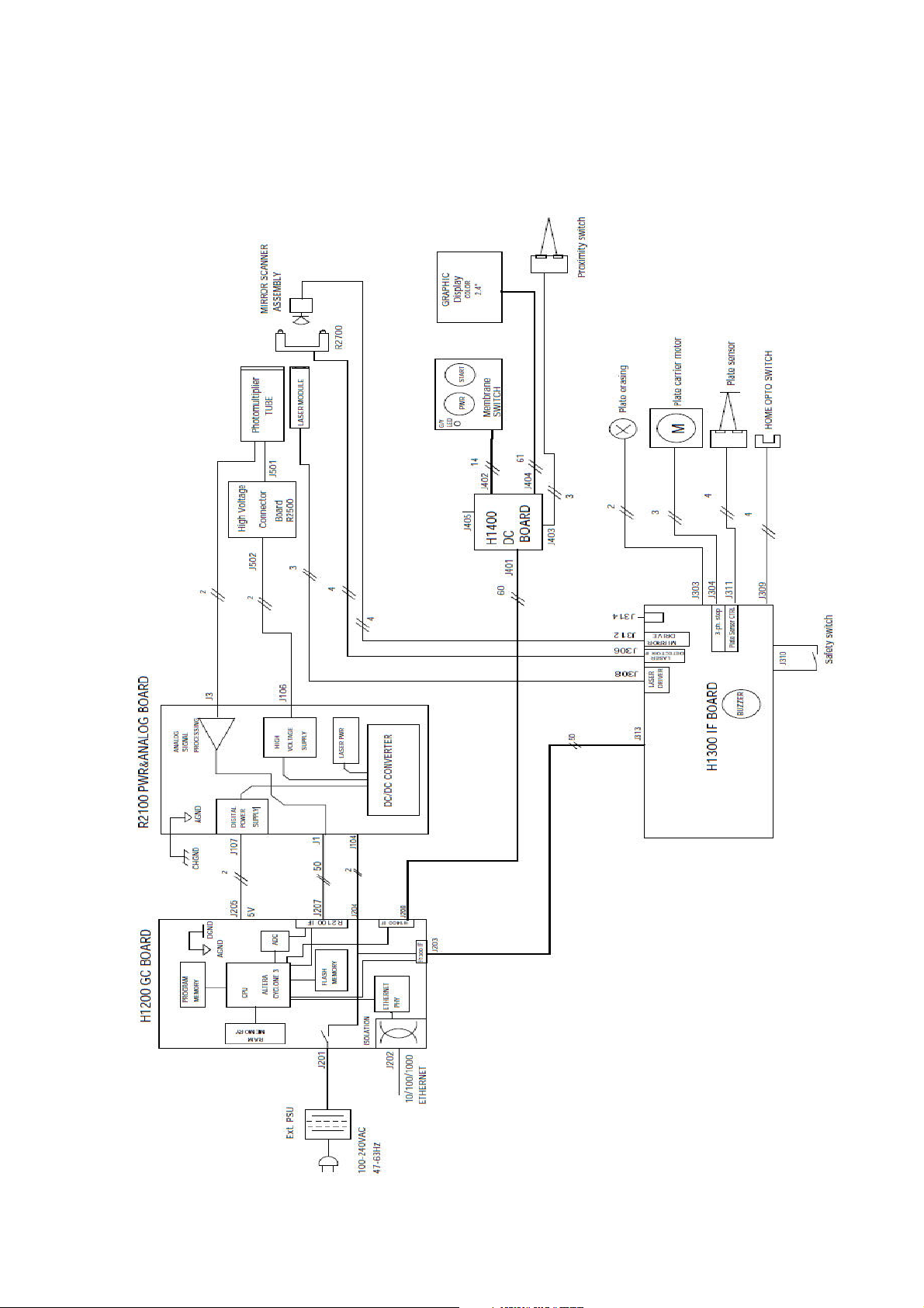
Block diagram
204724 rev5 Instrumentarium Dental 10
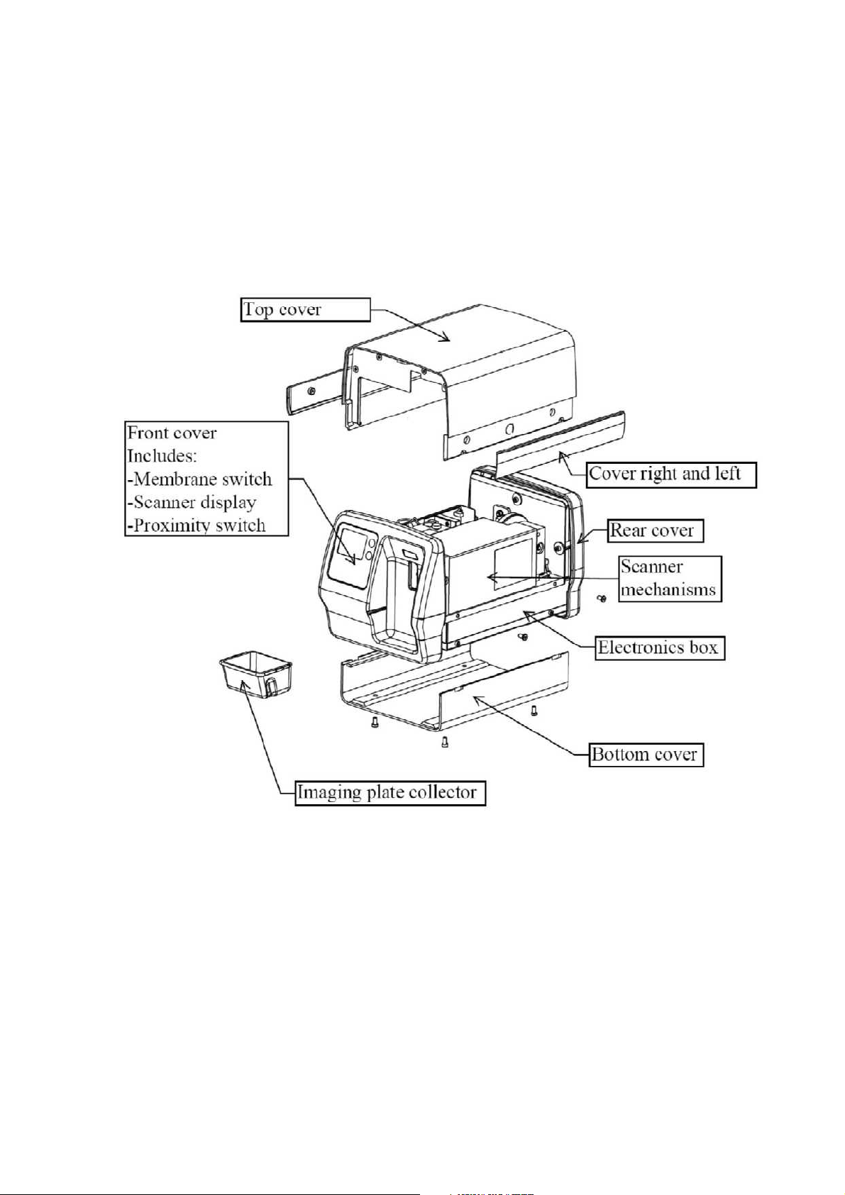
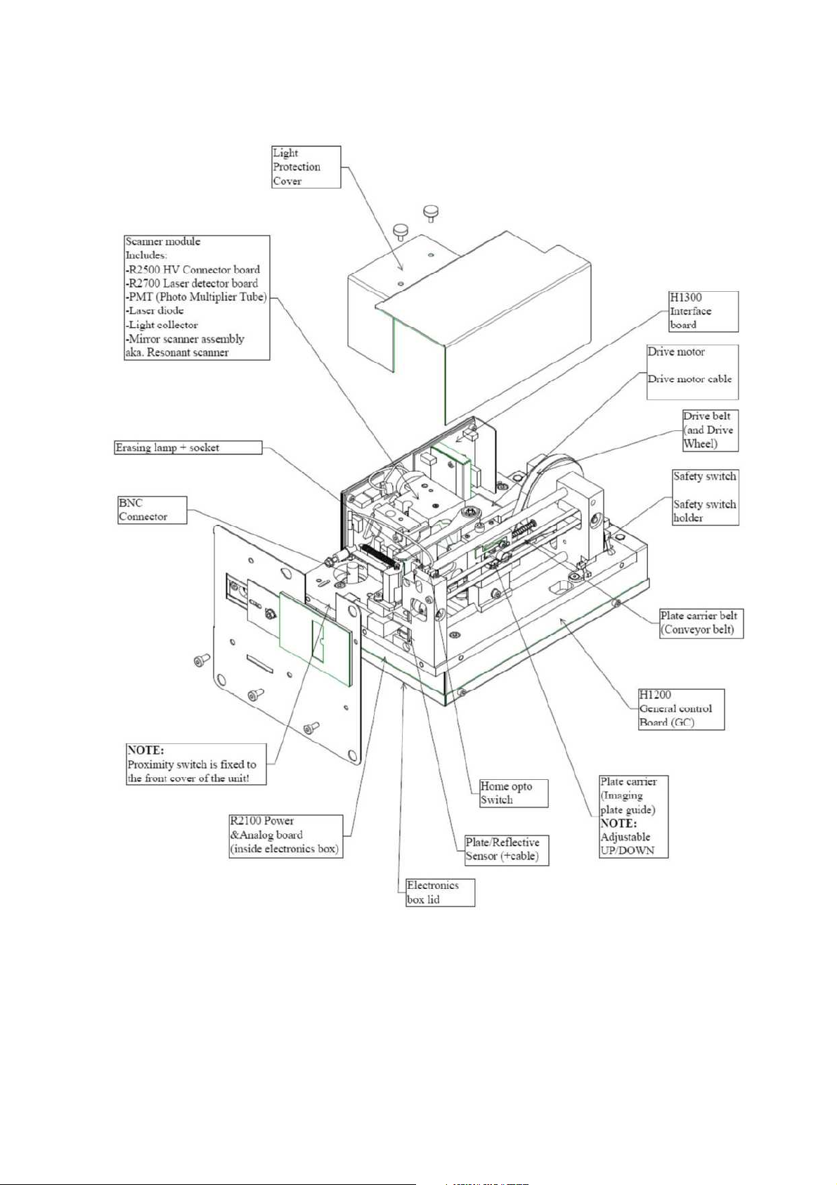
Scanner mechanics
External PSU is not shown here. See accessory catalog for details.
To open the unit covers you need 3mm hexagonal allen key.
204724 rev5 Instrumentarium Dental 11
204724 rev5 Instrumentarium Dental 12

Electronics
Powering and grounding of the boards:
• INPUT voltage 24VDC from External Power Supply is connected to H1200 General
Control board where supply voltage is split into two traces:
• To H1300 Interface Board
• R2100 Power and Analog Board
• Some of the boards are not powered directly = Their power is supplied and/or controlled
by other board(s).
• For proper operation all boards must be attached to the unit chassis.
External Power Supply Unit
• Universal input, auto switching (100-240 VAC / 47-63Hz).
• Output 24VDC / 2.9A / 70W (Powerbox type EMX805121 include adapters for most
commonly used power supply plugs) connected to the H1200 GC board.
• No serviceable parts inside. Do not open.
R2100 Power & Analog Board
• Analog signal processing circuitry
• Low voltage regulators for all boards & for laser
• High voltage power supply for PMT (J106 - thru R2500 connector brd)
• Analog signal from PMT J3
• Circuitry for checking the high voltage.
• Parallel data I/O between H1200 GC and this board
• 24Vdc input from H1200 (J201)
• +5Vdc digital supply to H1200 GC
• LED D2 is lit when high voltage is on
H1200 General Control Board
• System clock
• CPU inside FPGA (incl. Ethernet controller and other logic)
• System configuration flash-memory
• NAND flash memory
• General-purpose DDR2 memory
• Ethernet interface
• AD conversion
LEDs are used to indicate following voltages:
• D20 +5V
• D13 +1.2V
• D14 +1.8V
• D23 +3.3V
• If red led D19 is lit FPGA is in reset. This can mean that voltage +3.3V supplied to
FPGA is too low.
• LEDs 13, 14, 20 and 23 turn on after pressing power button
• D9 (L10) indicates that Ethernet PHY has established link at 10 Mbps
• D10 (L100) indicates that Ethernet PHY has established link at 100 Mbps
• D11 (L1000) indicates that Ethernet PHY has established link at 1000 Mbps (1Gbps)
204724 rev5 Instrumentarium Dental 13

H1300 Interface Board
• Interface for multiple controls (motor, laser control, home opto switch and imaging plate
detection), feedback and interface signals from and to H1200 -processor board.
• Controls erasing lamp on/off and generates a feedback of lamp current to CPU
H1400 Display & connector Board
• Interface between graphical display and H1200 GC Board
• Contains connector for proximity switch signals
• Connector for membrane switch panel push buttons and LED powering.
• Led D8 indicates if 5V is available at H1400 board.
R2500 High Voltage Connector Board
• Connects high voltage from HV-supply to the Photomultiplier tube (=PMT).
Membrane switch panel
• Membrane keyboard, which has one led and control keys in it.
• See user’s guide for more detailed description of keys and indicator light
NOTE! Membrane switch panel scan button and the proximity switch are parallel signals.
You are able to wake up the unit from the power save mode either way. Please refer to the
instructions of the <wakeup> command in service commands section for proper usage of
the proximity sensor activation / de-activation.
R2700 Laser detector board
• Contains two pin diodes that are used to synchronize laser movement.
204724 rev5 Instrumentarium Dental 14
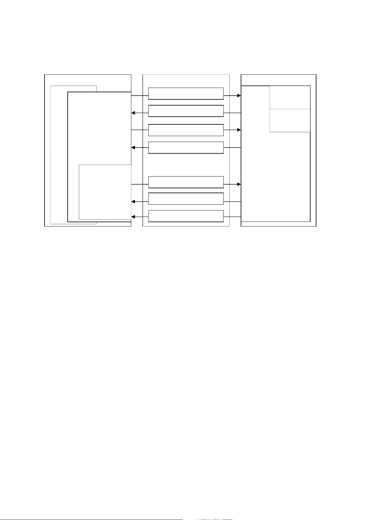
graphic files
Service Output Msg
Driver Cmd
Msg
Image Data Msg
Image Data Request Msg
User Cmd Reply Msg
User Cmd Msg
Driver Cmd Reply Msg
visible to user
Firmware
Architecture
Workstation (PC)
Imaging Application (optional)
Ethernet
Driver
(mandatory)
All messages
invisible to the
user.
Service
Terminal
(optional)
All messages
Imaging Application
• End user’s interface to acquired images.
• Handles image archiving and displaying.
Driver
• Handles the connection/communication to the unit
• Transfers and manipulates images.
• Unit cannot operate without Driver
There are two alternatives to be used as a driver:
1. DSD driver. Run from Application (or other imaging application)
2. s2terminal program. Run from the command prompt of Windows.
Service Terminal
• Optional part of the driver.
• Execute user commands
• View the service output of the unit.
There are two alternatives to be used as a Service terminal:
1. DSD driver. Run from Service Assistant of Application (or other imaging application).
2. s2terminal program. Run from the command prompt of Windows.
Scanner Firmware and Core (=FW, Inside the connected unit)
• Takes care of the normal unit operations.
• Operates either in normal mode or service mode.
o Normal mode: Unit is fully operational and images can be acquired.
o Service mode: Unit does not react to any other inputs than those given by the user
through service terminal. To be activated only from Service Terminal.
NOTE! Updating scanner FW may need updating of maximally 3 different binary files:
• Firmware
• Core
• Display graphics file
The scanner unit
Scanner Firmware , Core and display
Normal
mode
Service
mode
204724 rev5 Instrumentarium Dental 15

All updated files and related detailed instructions are described in the release letter of FW to be
updated. Short description of the used commands is listed on the chapter Field service
procedures.
204724 rev5 Instrumentarium Dental 16

Unit statuses and modes
Start-up sequence
1. Unit is powered on when power ON / OFF key is pressed
2. INITIALIZATION & SELF TEST SEQUENCE is indicated by animation ran while
performing following checks:
• Calculate the CRC
• Drive the plate carrier home (to reset the location counter)
• Drive the plate carrier back inside
• Calibrate PMT-signal amplifier
• Test high voltage (if safety switch is closed)
• Test erasing lamp
• Calibrate plate / reflective sensor DAC (if safety is closed)
• Wait the mirror scanner stabilizing (uses laser; close the safety switch after lamp
test to proceed without error if the cover is open)
• Drive the plate carrier to loading position
NOTE: if the light protection covers surrounding scanner module is removed (or safety
switch defective / cable disconnected). Unit goes into error state after erase lamp test and
self test sequence is halted (recovering from this needs restart of the unit)
However you are able to proceed with the start up sequence if safety switch is closed
manually AFTER the erasing lamp has been ON shortly during the startup sequence
NOTE! If the safety switch is pressed before the erasing lamp test
–the PMT may be damaged!!!!!
3. CHECK ANIMATIONS & ERROR CODE displayed if everything NOT OK
4. READY for operation (if connection to the application SW is OK)
Standby -mode
• Goes to standby –mode if not operated for a determined period of time:
o Factory set default can be changed by commanding <idle XXX>
XXX=time in seconds
o Unit wakes up from the standby mode by activation of the proximity sensor or by
pressing the start key
Powering “OFF” the unit
• Ready state:
o Power ON / OFF key pressed shortly >> BEEPS, but does not power off the unit
o Power ON / OFF key pressed more than one second >> powers off the unit
• Standby mode:
o Pressing of power ON / OFF key turn off the unit
Automatic shutdown
• Unit is powered off automatically if the unit stays in the standby mode for a longer period
of time than set in the <off> parameter:.
o Factory set default can be changed by commanding <off XXX>
XXX=time in minutes
Image read, but the connection lost during the read out of the imaging plate (application
etc.)
• Scanner unit display shows “check application animation” indicating that there is image
in the memory which is not transferred to the driver
204724 rev5 Instrumentarium Dental 17

• Drives the carrier in
• Will not shutdown automatically
• Does not allow switching off the power (continuously beep when pressed) until the
image is transferred.
204724 rev5 Instrumentarium Dental 18

Service Terminal
Service terminal is not an end user interface and training to use it in advance is
mandatory to prevent the changing of unit configuration (=resulting the unit to become
inoperative) accidentally.
Be very careful not to use service commands without the necessary know-how. Gain knowledge
by going through all useful commands and train their usage in practice with scanner unit.
All service terminal commands and functions are not explained in this manual. They are
instructed in the scanner firmware help (which is accessible through service terminal).
This arrangement is to keep the documentation up to date, since the service terminal
instructions for commands are always up to date in the scanner firmware.
Therefore this manual explains only the principles of the main commands.
More detailed instructions of Service Terminal commands can be found later in this document
and in their help outputs <h [command]>.
Accessing Service Terminal
• Service terminal commands are controlled either from imaging applications Service
Assistant or from s2terminal
NOTE: Only have either imaging application (Service Assistant) OR s2terminal
open at one time.
• Service commands are executed by scanner unit
Access service terminal Using s2terminal Program
• THIS IS THE RECOMMENDED WAY TO ACCESS SERVICE TERMINAL
o Firmware and core upgrade can only be performed with s2terminal
• s2terminal program is run from the command prompt of Windows.
• Application must be closed when accessing service terminal from s2terminal If
Application is opened at the same time, you will have a “login fail (no connection)” error
message on screen when trying to make the connection.
Note the difference of actual command prompt and the s2terminal program running in it:
• The input and output of the s2terminal and of the command prompt look similar.
• However, the functions and commands available in the command prompt are not
available in the s2terminal and vice versa.
• If you get confused it is good idea to check the title bar of the command prompt window
- it should read “s2terminal” when the s2terminal program is running.
- it reads “cmd.exe” when only Command Prompt is running
• Running the s2terminal program needs the following files:
• s2terminal.exe (Must be version dated 22/05/2009 or later)
• s2.dll (Must be version dated 21/05/2009 or later)
• W32N55.dll (Must be version dated 23/10/2007 or later)
• (s2terminal has to be version 3.2.127.0 or later)
1. Copy all these files to one same and dedicated service folder that you may need to
create (in following example “c:\s2terminal” folder is used to store s2terminal files)
2. Select from Windows: Start / Programs / Accessories / Command Prompt
Or
Select from Windows: Start / run
204724 rev5 Instrumentarium Dental 19

3. Type into “Open” -field: <cmd>
4. Choose OK
Command prompt examples :
• <cd\> (Changes to the root directory =C:\)
• <cd s2terminal> (changes to directory “s2terminal”)
5. CHECK THAT Application IS NOT OPENED
6. Type <s2terminal> in the command prompt to see the instructions for the command
syntax. Then execute the program using the unit’s IP -address.
7. Type <s2terminal 192.168.2.11>:
• Starts the Service Terminal for unit having ip 192.168.2.11
Or
Type <s2terminal 192.168.2.11 –c>:
• Starts the service terminal and configures ip –address to scanner unit 192.168.2.11
NOTE: Keep start button pressed when entering <s2terminal 192.168.2.11 –c>:
8. If the IP-address is correct and the s2terminal program is able to connect to the unit, it
prints out terminal output of the login command, which displays “s2terminal, the unit’s
firmware version(s), serial number and some parameters”. Otherwise it displays an error
message(s).
NOTE: It is normal that you may have few times “login fail (no connection)” –error
also in normal functioning connection
9. Quit s2terminal program by <xq>
Access service terminal with Service assistant –utility from the imaging application
• THIS IS THE ALTERNATIVE WAY (backup) TO ACCESS SERVICE TERMINAL
o Use when imaging application –connection available
o Firmware download CAN NOT be performed from Service Assistant
• Application connected, press CTRL+ALT+SHIFT+E simultaneously
>> Opens imaging software Service Assistant
NOTE: If operating in Express Share configuration, the unit must be reserved before accessing
service assistant by pressing “CTRL+ALT+SHIFT+E” buttons
204724 rev5 Instrumentarium Dental 20
 Loading...